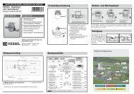
9. Schaltgerät - Kessel
9. Schaltgerät - Kessel
9. Schaltgerät - Kessel

Create successful ePaper yourself
Turn your PDF publications into a flip-book with our unique Google optimized e-Paper software.
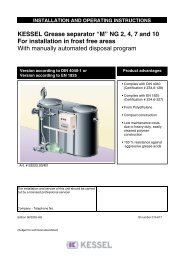
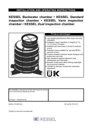
ANLEITUNG FÜR EINBAU, BEDIENUNG UND WARTUNGKESSEL-Hebeanlage AqualiftF (400V) Standardfür fäkalienhaltiges und fäkalienfreies Abwasserzur freien Aufstellung in frostgeschützten RäumenBedienungsanleitungSeite 1-44Installation ManualPage 45-88Guide L´InstallationPagina 89-132Istruzione InstallazionePagina 133-176Handleiding voor inbouwPagina 177-220Aqualift F Aqualift F Duo ProduktvorteileEinfacher Anschluß überangeformte StutzenAnbohrflächen für weitereAnschlüsseVollautomatischer BetriebWartungsfreundlicherPE-BehälterAllgemeine bauaufsichtlicheZulassung Nr. Z-53.2-424LGALandesgewerbeamt BayernBauartgeprüftund überwachtmit Sicherheitgeprüfte QualitätInstallation Inbetriebnahme Einweisungder Anlage wurde durchgeführt von Ihrem Fachbetrieb:Name/Unterschrift Datum OrtStand 05/2012Stempel FachbetriebSach-Nr. 206-818Techn. Änderungen vorbehalten
1. SicherheitshinweiseAllgemeine SicherheitsvorkehrungenBei Installation, Betrieb, Wartung oder Reparatur der Anlage sind die Unfallverhütungsvorschriften, diein Frage kommenden DIN- und VDE-Normen und Richtlinien sowie die Vorschriften der örtlichen Ener -gie- und Versorgungsunternehmen zu beachten.Die Anlagen dürfen nicht in explosionsgefährdeten Bereichen betrieben werden.Gefahr durch elektrische SpannungDiese Anlage enthält elektrische Spannungen und steuert drehende, mechanische Anlagenteile. BeiNicht beachtung der Bedienungsanleitung können erheblicher Sachschaden, Körperverletzung oder gartöd liche Unfälle die Folge sein.Vor allen Arbeiten an der Anlage ist diese sicher vom Netz zu trennen. Bauseitiger Hauptschalter undSi cherungen müssen abgeschaltet, d.h. spannungsfrei geschalten und gegen Wiedereinschalten gesichertwerden. Sind nur Sicherungen vorhanden, sind diese auszuschalten und mit einem Hinweis zuver sehen, damit dritte Personen die Hauptsicherung nicht wieder einschalten können.Für alle elektrischen Arbeiten an der Anlage gilt die VDE 0100.Das Schaltgerät sowie die Niveausteuerung stehen unter Spannung und dürfen nicht geöffnet werden.Nur Elektrofachkräfte dürfen Arbeiten an den elektrischen Einrichtungen durchführen. Der Begriff Elektrofachkraftist in der VDE 0105 definiert.Es ist sicherzustellen, dass sich die Elektrokabel sowie alle anderen elektrischen Anlagenteile in einemein wandfreien Zustand befinden. Bei Beschädigung darf die Anlage auf keinen Fall in Betrieb genommenwerden bzw. ist umgehend abzustellen.Verbrennungsgefahr für Hände und FingerDer Antriebsmotor kann während des Betriebes eine hohe Temperatur entwickeln.Verletzungsgefahr für Hände und FingerDie Pumpen sind mit geschlossenem Kanalrad ausgestattet. Arbeiten an der Pumpe dürfen deshalb nurdurchge führt werden, wenn der Strom abgeschaltet ist und sich bewegende Teile nicht mehr drehen.Bei Wartungs- und Reparaturarbeiten ist auf scharfe Kanten zu achten.Gefahr durch große GewichteDie Hebeanlagen wiegen als Ausführung mit einer Pumpe ca. 45 kg, als Ausführung mit zwei Pumpenca. 84 kg. Die Anlagen dürfen nur zu zweit mit entsprechender Vorsicht und Schutzausrüstung (z. B. Sicherheitsschuhe)angehoben bzw. montiert werden.Die Pumpen dürfen nur zu zweit (mit geeigneter Sicherung gegen Abrutschen) langsam abgenommenoder in die Pumpenflanschöffnung eingesetzt werden.2
1. SicherheitshinweiseGesundheitsgefahrDie Abwasseranlage fördert fäkalienhaltiges Abwasser, welches gesundheitsgefährdende Stoffe enthal -ten kann. Bei allen Arbeiten an der Anlage ist darauf zu achten, dass kein direkter Kontakt zwischendem Ab wasser oder davon verschmutzten Anlagenteilen und Augen, Mund oder Haut stattfindet. Beieinem di rekten Kontakt ist die betroffene Körperstelle sofort gründlich zu reinigen und ggf. zu desinfizieren.Dar überhinaus kann die Atmosphäre im Behälter u.U. gesundheitsgefährdend wirken. Vor demÖffnen der Reinigungsöffnung (oder Abnehmen der Pumpe) ist deshalb dafür zu sorgen, dass ein ausreichenderLuftaustausch im jeweiligen Raum stattfindet bzw. während dem Öffnen eine entsprechende(Zwangs-) Entlüftung erfolgt.LärmbelästigungWährend des Betriebes der Pumpe ist mit einer Geräuschentwicklung zu rechnen, die je nach Einbausi -tua tion störend wirken kann. Sofern Anforderungen an die maximal zulässige Lautstärke gestellt werden,sind hierfür gegebenenfalls entsprechende Maßnahmen bauseits vorzusehen. Eventuell kann auchdas KESSEL-Set zur Schalldämmung ausreichend Abhilfe schaffen. Empfehlenswert ist dazu dieoptionale Schalldämmmatte (Monoanlage Art.-Nr: 28962; Duoanlage Art.-Nr. 28693).ExplosionsgefahrDas Innere des Behälters gilt nach EN 12050 als explosionsgefährdeter Raum, da durch biologischeFaul prozesse brennbare Gase (Schwefelwasserstoff, Methangas) entstehen können. Beim Abschraubender Pumpe oder des Reinigungsdeckels oder anderer Teile ist deshalb dafür zu sorgen, daß einaus reichender Luftaustausch im jeweiligen Raum stattfindet bzw. während dem Öffnen eine entsprechende(Zwangs-) Entlüftung erfolgt. Während der Behälter geöffnet ist, darf in dem jeweiligen Raumnicht geraucht werden und dürfen auch keine anderen Tätigkeiten ausgeführt werden, die zu einer Gas -ent zündung führen könnten (z. B. Betrieb elektrischer Geräte ohne gekapselten Motor, Metallbearbeitungetc.).3
Inhaltsverzeichnis1. Sicherheitshinweise ...........................................................................................................Seite 22. Allgemeines 2.1 Einsatzbereich.....................................................................Seite 52.2 Anlagenbeschreibung..........................................................Seite 53. Technische Daten 3.1 Abmessungen......................................................................Seite 63.2 Pumpen ...............................................................................Seite 73.3 Elektrisches Schaltgerät ......................................................Seite 84. Einbau und Montage 4.1 Montage Sammelbehälter ...................................................Seite 94.2 Anschluß der Rohrleitungen ................................................Seite 94.3 Einstellung der Druckniveauschalter ...................................Seite 115. Elektroanschluss 5.1 Allgemeine Hinweise ...........................................................Seite 125.2 Montage des Schaltgeräts...................................................Seite 125.3 Installation, Verdrahtung......................................................Seite 135.4 Kontrollen ...........................................................................Seite 165.5 Konfiguratiion Schaltgerät ...................................................Seite 176. Inbetriebnahme 6.1 Allgemeine Hinweise ...........................................................Seite 186.2 Druckabgangsstutzen..........................................................Seite 186.3 Bedienung Schaltgerät ........................................................Seite 186.4 Funktionsbeschreibung .......................................................Seite 196.5 Funktionstest .......................................................................Seite 197. Inspektion und Wartung 7.1 Hinweise zur Pumpe............................................................Seite 207.2 Hinweise zur Anlüftevorrichtung ..........................................Seite 207.3 Hinweise zum elektrischen Schaltgerät...............................Seite 218. Störungen und 8.1 Allgemeine Störungen .........................................................Seite 22Abhilfemaßnahmen 8.2 Störungsmeldungen ............................................................Seite 248.2.1 Irreguläre Niveauzustände ..................................................Seite 268.2.2 Interne Überwachung ..........................................................Seite 278.2.3 Meldung “Störung”...............................................................Seite 278.2.4 Meldung “Alarm” ..................................................................Seite 278.2.5 Was tun wenn… ..................................................................Seite 27<strong>9.</strong> Schaltgerät <strong>9.</strong>1 Schaltgerät (ab Baujahr 01/10)............................................Seite 28<strong>9.</strong>2 Schaltgerät (bis Baujahr 12/09) ...........................................Seite 2910. Ersatzteile und Zubehör 10.1 Zubehörteile.........................................................................Seite 3410.2 Ersatzteile............................................................................Seite 3511. Gewährleistung ...........................................................................................................Seite 4012. Konformitätserklärung ...........................................................................................................Seite 4113. Übergabeprotokoll ...........................................................................................................Seite 424
2. Allgemeines2.1 EinsatzbereichDie Hebeanlagen fördern die unterhalb der Kanal- und Rückstauebeneanfallenden fäkalienhaltigen und fäkalienfreienAb wässer entsprechend den Vorschriften der DIN 1986 vollautomatischin den Kanal. Sie sind grundsätzlich nur fürhäus liches Abwasser, beispielsweise in Ein- und Mehrfamilienhäusern,Gewerbebetrieben, Hotels und Restaurants,Kauf häusern, Krankenhäusern, Schulen oder ähnlichen Fälleneinzusetzen.Wenn der Zufluss der Hebeanlage während des normalenBe triebes nicht unterbrochen werden darf, muss dieHebean la ge zusätzlich mit einer zweiten Fördereinrichtungmit gleicher Leistungsfähigkeit ausgerüstet werden, die sich- sofern er forderlich - selbsttätig einschaltet (Doppel- stattEinzel-Anlage).Die KESSEL-Hebeanlage Aqualift ® F ist zur freien Aufstellungin frostgeschützten Räumen vorgesehen. Das zuge hö -ri ge Schaltgerät ist in einem überflutungssicheren, trockenenund frostgeschützten Raum zu installieren. Die Abwassertauchpumpensind mit einem Einkanallaufrad ausgestattetund verfügen über einen freien Kugeldurchgang von 40 mm.Die Druckleitungen sind mindestens in DN 80, die Lüftungsleitungenmindestens in DN 70 auszuführen. Abrasive Me -dien sind vom Pumpenlaufrad fernzuhalten.Die Anlagen sind für andauernde Abwassertemperaturen bis35°C geeignet. Kurzzeitig (bis 10 Minuten) ist eine maxima -le Temperatur von 60°C zulässig.2.2 AnlagenbeschreibungDie KESSEL-Hebeanlagen Aqualift ® F als Einzel- oder Doppelanlagebesteht grundsätzlich aus folgenden Baugruppen:1.8 1.3 1.51.41.31.41.61.91.51.61.21.21.71.11.81.11.71. Sammelbehälter aus PEHDgas- und wasserdicht, mit1.1 ein bzw. zwei Abwasserpumpenmit jeweils 5 m Anschlußleitung1.2 pneumatische Niveausteuerungmit jeweils 5 m Luftschlauch1.3 Reinigungsöffnung1.4 Anschluss für Zulaufleitung DN 1001.5 Anschluss für Entlüftungsleitung DN 701.6 Anschluss für Handmembranpumpe DN 32 / ø 40 mm1.7 Druckabgangsstutzen DN 100 mit integrierterRückschlagklappe und Anlüftevorrichtung1.8 Anbohrflächen2. Elektrisches Schaltgerät(siehe Abbildungen in Kapitel 8)3. Zubehörteile (ohne Abbildung)3.1 Winkel mit Schrauben und Dübel zur Behälterbefestigungam Boden3.2 Gummischlauch mit Schlauchklemmen für Druckleitungsanschluß3.3 Schalldämmende UnterlegematteMono: Art.-Nr. 28692Duo: Art.-Nr. 28693Eine detaillierte Beschreibung des Anlagenaufbaus befindetsich in Kapitel 10, Ersatzteile.5
3. Technische Daten3.1 Abmessungen3.1.1 Einzelanlage 1,1 kW mit Druckabgang DN 100, Best.-Nr. 28645 / 28644 (mit Absperreinrichtung)Einzelanlage 2,2 kW mit Druckabgang DN 100, Best.-Nr. 28647 / 28649 (mit Absperreinrichtung)DN100Ø110DN70Ø75475DN32Ø40 DN100Ø110Zulaufhöhe1801545255643.1.2 Doppelanlage 1,1 kW mit Druckabgang DN 100, Bestell.-Nr. 28652 / 28659 (mit Absperreinrichtung)Doppelanlage 2,2 kW mit Druckabgang DN 100, Bestell.-Nr. 28634 / 28631 (mit Absperreinrichtung)539DN100Ø110DN70Ø75DN100Ø110DN32Ø40 DN100Ø110Zulaufhöhe3001607807736
3. Technische Daten3.2 Pumpen (Aqualift F Mono, Duo)Typ 400 V - 1,1 kW 400 V - 2,2 kWNennleistung (P2) 1,15 kW 2,4 kWAufnahmeleistung (P1) 1,6 kW 3,1 kWBetriebsspannung400 V DSNennfrequenz50 HzNennstrom 3,2 A 5,4 AAnlaufstrom 14,4 A 30,8 AAbsicherung3 x 16 A trägeAnschlußleitung 5 m Länge, 7 x 1,5 mm 2Förderguttemperatur 35 °CGewicht (Pumpe) 30 kg 31 kgSchutzartIP 68 ( 24h; 3m WS)Betriebsart S1 S3max. Dauerlaufzeit 240 Min.30% EinschaltdauerSchallpegel < 70 db < 70 dbPumpvolumen20 l (Mono), 50 l (Duo)LeistungsdiagrammFörderhöhe m1514131211109876543210Q min nach DIN 1986 (vmin = 0,7m/s) für DN 80230 V1,1 kWQ min nach DIN 1986 für DN 100400 V1,1 kW0 4 8 12 16 20 24 28 32 36 40 44 46 48 50 52 54 56 58Fördermenge Q (m 3 / h)400 V2,2 kW7
3. Technische Daten3.3 Elektrisches Schaltgerät3.3.1 Allgemeine technische DatenUmgebungsbedingungenZulässiger Temperaturbereich: 0 bis 50 °CZulässige Luftfeuchtigkeit: 10 bis 80 %nicht kondensierendmaximale Betriebshöhe: 2000 m über NNLeistungsaufnahmemax. ca. 11 VA für Einfach-, 15 VA für Doppelanlage(Elektronik ohne Motor)SchutzklasseKlasse 1 mit Funktionserdung des Sekundärkreises derElek tronik (PELV)SchutzartIP 54 bei sachgerechter Montage3.3.2 VersorgungNetzanschlussPE/N/L1/L2/L3 laut Kennzeichnung am Klemmenblock fürEinzelanlage / DoppelanlageBetriebsspannung400 / 230 V 3~ 50 Hz ± 10% Drehstrom (L1=230V AC /50Hz±10% zur Versorgung der Netzteile der Elektronik)Erforderliche Vorsicherungmax. 16 A / Phase (Installationsseitig vorzusehen)3.3.3 Eingängea) ab Baujahr 01/10Niveaueingänge jeweils ca. 24 V Ausgang; ca. 5 mA EingangJede Pumpe hat den Stromkreis TF1 und TF2Relais „Störung“Wechsler; Öffner, Mittelkontakt, Schließer jeweils max. 2ARelais „Warnung“Wechsler; Öffner, Mittelkontakt, Schließer jeweils max. 2ANetz2 x N, max. je 2A2 x L, max. je 2Azur Speisung von Störungs-/Alarmmeldegeräten, geschaltetüber die „Störung“-/„Warnung“-Relais, ohne geräteinterneSicherungMotor (Einzelanlage)Motor PE Netzanschluß}max. 4kW(graue Doppelstockklemmen bis Bj. 01/10)(Federklemme auf Platine ab Bj. 01/10)Motor U T1 SchützMotor V T2 SchützMotor W T3 SchützMotor 1/2 (Doppelanlage)Motor 1/2 PE Netzanschluß(4-fach Netzdurchgangsklemmen bis Bj.01/10)(Federklemme auf Platine ab Bj. 01/10)Motor 1/2 U T1 Schütz 1/2Motor 1/2 V T2 Schütz 1/2Motor 1/2 W T3 Schütz 1/2}max.4kWb) bis Baujahr 01/10Niveaueingänge jeweils 15,8 V Eingang ca. 5 mAStromkreis TF (bzw. TF1 und TF2) und E7 (bzw. E7 und E8)zum Anschluss des Temperaturschalters des Pumpenmotors,Geberspeisung Eingang max. 18 mA für TF und 9 mA für E73.3.4 Ausgänge8
4. Einbau und MontageIm Lieferumfang sind folgende Teile enthalten (siehe Abschnitt2.2):- Sammelbehälter mit allen montierten Bauteilen- elektrisches Schaltgerät- ZubehörteileWICHTIG:Das elektrische Schaltgerät ist frostfrei und trocken aufzu -be wahren. Wenn die Anlage beim Einbau noch nicht elektrischangeschlossen wird, ist das Schaltgerät inkl. allerElektroteile dementsprechend aufzubewahren.ACHTUNG:Gefahr durch große Gewichte. Die Hebeanlagen wiegenje weils ca. 45 kg (Einzelanlage) und ca. 84 kg (Dop -pel anla ge). Die Teile dürfen nur in geeigneter Weise mitent sprechender Vorsicht und Ausrüstung angehobenbzw. montiert werden. Ein Sturz der Anlagen kann zu irre -pa rablen Schäden an An lagenteilen (z. B. Pumpe) oderder gesamten Anlage füh ren. Diese Schäden sind nichtdurch die Garantie abgedeckt.EINBAUORT:Die KESSEL-Hebeanlage Aqualift ® F ist zur freien Aufstellungin frostgeschützten Räumen vorgesehen. Daszu ge hö rige Schaltgerät ist in einem überflutungssicheren,tro cke nen und frostgeschützten Raum zu installieren.4.2 Anschluß der RohrleitungenAlle Rohrleitungen sind grundsätzlich so zu verlegen, daßdie se von selbst leerlaufen können. Alle Leitungsanschlüssemüssen flexibel und schalldämmend ausgeführt werden.Generell sind zwei Anschlussarten möglich:I. Nutzung der vorhandenen, angeformten Stutzen amBe hälter (für Anschluß von Zulaufleitung, Entlüftung undHandmembranpumpe gemäß Abb. A und B) mittels Abschneidender „Frontkappe“ gemäß Abb. C.Entlüftung DN 70 (Da=75mm)BodenbefestigungZulauf-AnschlußDN 100(Da=110mm)4.1 Montage SammelbehälterUm unproblematische Montage-, Pflege- und Wartungsarbeitenan den Hebeanlagen zu ermöglichen, müssen dieseim mer so eingebaut werden, dass zu allen Bereichen der Hebeanlageeine ausreichende Zugänglichkeit und bei allenBau teilen eine Austauschbarkeit gewährleistet ist. GemäßDIN 1986 ist dazu ein Freiraum von mindestens 60 cm umdie Anlage vorzusehen (zu allen Seiten und nach oben).Die Anlage ist an entprechender Stelle im Raum waagrechtaus zurichten und zweckmäßig auf schalldämmendem Mate -rial (als Zubehör bei KESSEL erhältlich) aufzustellen. DieHe beanlage ist mit den mit gelieferten Winkeln, Schraubenund Dübeln fest mit dem Boden zu verbinden, um sie gegenVer schieben oder Verdrehen zu sichern.Behälter-HebeanlageBefestigungswinkelAnschluß-Handmembran -pumpe DN 32 (Da=40mm)Abb. A: EinzelanlageEntlüftung DN 70 (Da=75mm)Zulauf-AnschlußDN 100 (Da=110mm)Anschluß-Handmembranpumpe DN 32(Da=40mm)Dämpfungsmatte(optional)Abb. B: DoppelanlageBoden9
4. Einbau und MontageÜber den Stutzen kann eine handelsübliche Kunststoffrohrmuffeübergeschoben werden (siehe Abb. C).Alternativ kann auch der Anschluss eines Kunststoffrohresmit DN 100 für den Zulauf oder DN 70 für die Entlüftung mittelsVerbindungsschellen oder Gummigewebeschlauch mitSchlauchklemmen* erfolgen. Damit die dabei auftretendenho hen Spannungskräfte zu keiner Verformung am Stutzenfüh ren, muß dazu in das obere Ende des Stutzens ein geeig -ne ter Stützring* eingeschoben werden (siehe Abb. D).RohranschlußSchlauchschelleSchlauchschellenStutzen absägenStutzenabsägenÜbergangsschlauchstückStützringZulauf-AnschlußAbb. D:II. Anschlüsse an den seitlich angeordnetenAnbohrflä chen (für Zulaufleitung oder Handmembranpumpe)mittels Bohrung mit Sägeglocke*, Einfügen derpassenden, eingefetteten Dichtung* sowie Einschiebeneines passenden Kunststoffrohres (siehe Abb. E)Behälter-HebeanlageRohrdurchführungs-DichtungAbb. C:RohranschlußÖffnunggebohrtBehälter-HebeanlageAbb. E* KESSEL-Zubehörteil10
5. ElektroanschlussDie einzelnen Anschlußarbeiten sind in der nachfolgenden Tabelle sowie in den Anschlußplänen auf den Seiten 27 und 29auf geführt. Zu beachten sind dabei auch die jeweiligen Erläuterungen in Kapitel 8, Elektrisches Schaltgerät (Lage der Bedienelemente,Innenansicht des Schaltgerätes).EINZELANLAGE - Sicherheitshinweise beachten !Auszuführende Arbeit Schaltgerät ab Bj. 01/10 Schaltgerät bis Bj. 12/09Batterieanschluss(Akkus bis Baujahr 12/09)NetzanschlußBeide Batterien (2 x 9V-Block) sindauf der Platine anzuschliessen.• Netzzuleitung L1 / L2 / L3 / N / PEam Klemmenblock mit Schraubanschlussanschließen.• N und PE müssen zwingend angeschlossenwerden.• Die Netzzuleitung muß installationsseitigeinen allpoligen Hauptschalteraufweisen, der der Steuerungeindeutig zugeordnet ist.• Die vorgeschriebene installationsseitigeVorsicherung darf 16A jePhase nicht überschreiten.• Bei Fehlanschluß kann die Steuerungbeschädigt oder zerstört werden.• Der Akku (1 x 9V-Block) ist in die Akkuhalterungeinzustecken.• Netzzuleitung L1 / L2 / L3 / N / PE an die obereEbene des grauen Netzanschluß-Klemmenblocksanschließen, dabei Kennzeichnung(Platinenaufdruck) beachten.• N und PE müssen zwingend angeschlossenwerden.• Die Netzzuleitung muß installationsseitigeinen allpoligen Hauptschalter aufweisen, derder Steuerung eindeutig zugeordnet ist.• Die vorgeschriebene installationsseitige Vorsicherungdarf 16A je Phase nicht überschreiten.• Bei Fehlanschluß kann die Steuerung beschädigtoder zerstört werden.MotorzuleitungMotortemperaturfühlerNiveauerfassung• Motorzuleitung U/V/W ist an denSchütz sinnrichtig in die unterenSchraubklemmen T1 / T2 / T3 anzuschließen.Dabei ist die Drehrichtungdes Motors zu beachten.• PE ist zusammen mit TF1 und TF2an dem Klemmenblock auf derPaltine unerhalb des Motorschutzschaltersanzuklemmen.• Die Ader 4 der Motorzuleitung ist indie unterste Klemme des KlemmenblocksTF2 TF1 anzuschließen.Ader 5 der Motorzuleitung ist in diemittlere Klemme des KlemmblockssTF 2 TF1 anzuschließen.Der Eingang TF2 ist mit einer 2-poligenSteckbrücke gebrückt; d.h.die mittlere Klemme ist doppelt belegt.Steckbrücke darf nicht entferntwerden!Anschluss am DrucksensorDer transparente Luftschlauch iststetig steigend zum Schaltgerät zuverlegen. Der Luftschlauch mussdicht an dem am Schaltgerät vorgesehenenAnschluss festgeschraubtwerden.• Motorzuleitung U/V/W ist an den ABB-SchützB6-30-10 links des Motorschutz-schalterssinnrichtig in die unteren Schraubklemmen T1/ T2 / T3 anzuschließen. Dabei ist die Drehrichtungdes Motors zu beachten.• PE an die untere Ebene des grauen Netzanschlußklemmenblocksunter Beach tung derKennzeichnung (Platinenaufdruck) anschließen.• Eingang TF: Die Ader 4 der Motorzuleitung istrechts an den TF-Eingang, die Ader 5 links anden TF-Eingang anzuschließen.• Eingang E7: Die Brücke ist zu belassen.Niveaueingänge (EIN/ALARM)• Das Kabel ist stetig steigend zum Schaltgerätzu verlegen.• Die Kabelenden des Druckniveauschalterssind an die entsprechend gekennzeichnetenKlemmen anzuschließen. (weiße Litze rechts,braune Litze links an Eingang „Ein“, grüneLitze rechts und gelbe Litze links an Eingang„Alarm“).13
5. ElektroanschlussEINZELANLAGE - Sicherheitshinweise beachten !Auszuführende Arbeit Schaltgerät ab Bj. 01/10 Schaltgerät bis Bj. 12/09• Der Klemmenblock der Niveaueingänge darfmit keinem anderen Stromkreis ver bundenwerden.• Die Klemmen sind mit Schaltersymbolen gekennzeichnet.• Die Ausgänge N / L1 (je 2) sind vorgesehen,um über die Relais „Störung“ und „Alarm“ externeMeldeeinrichtungen / Anzeigen zu versorgen.Sie dürfen nicht für andere Zweckeverwendet werden.• Der maximal zulässige Strom beträgt 2A.Ausgänge„Störung“ und „Alarm /Warnung”Die „Störung“- und „Warnung“-Meldungerfolgt über je ein Relais(Wechsler) ohne Schutzbeschaltung.Induktive Lasten müssen externentstört werden. Der Ruhezustand(stromlos) der Relais ist aufder Platine aufgedruckt. Er bedeutet„Stö rung“- und „Warnung”-Meldungist eingeschaltet.• 42 V dc/ 0,5 A• Die „Störung“- und „Alarm“-Meldung erfolgtüber je ein Relais (Wechsler) ohne Schutzbeschaltung.Induktive Lasten müssen externentstört werden. Der Ruhezustand(stromlos) der Relais ist auf der Platine aufgedruckt.Er bedeutet „Stö rung“- und„Alarm“-Meldung ist eingeschaltet.• Die Relaiskontakte weisen keine interneVerbindung zu irgendeiner der VersorgungsoderBetriebsspannungen der Steuerungauf und sind von diesen sicher ge trennt biszu einer Arbeitsspannung von 300 V nachTabelle D.10 der Norm EN 61010 (Überspannungskategorie2 u. Verschmutzungsgrad2).• Die Relais sind ausgelegt zum Schalten von230 V / 2 A. Der Strom ist extern durch geeigneteMaßnahmen auf diesen Wert zu begrenzen.• Es ist nicht gestattet, mit den Relais verschiedenePhasen zu schalten. Die Phasedarf jedoch von L1 abweichen.14
5. ElektroanschlussDOPPELANLAGE - Sicherheitshinweise beachten !Auszuführende Arbeit Schaltgerät ab Bj. 01/10 Schaltgerät bis Bj. 12/09Batterieanschluss(Akkus bis Baujahr 12/09)NetzanschlußMotorzuleitungMotortemperaturfühlerNiveauerfassung• Beide Batterien (2 x 9V-Block) sindauf der Platine anzuschliessen.• Netzzuleitung L1 / L2 / L3 / N / PE amKlemmenblock anschließen, L1 / L2/L3 / N / PE mit Schraubanschlussanschließen.• N und PE müssen zwingend angeschlossenwerden.• Die Netzzuleitung muß installationsseitigeinen allpoligen Hauptschalteraufwei sen, der der Steuerung eindeutigzugeordnet ist.• Die vorgeschriebene installationsseitigeVorsicherung darf 16A jePhase nicht überschreiten.• Bei Fehlanschluß kann die Steuerungbeschädigt oder zerstört werden.• Die Motorzuleitungen 2 x U/V/W sindan die Schütze sinnrichtig in die unterenSchraubklemmen T1 / T2 / T3anzuschließen (Pumpe 1 links,Pumpe 2 rechts). Dabei ist die Drehrichtungder Motoren zu beachten.• PE ist zusammen mit TF1 und TF2an dem Klemmenblock auf derPaltine unerhalb des Motorschutzschaltersanzuklemmen.PUMPE 1/2: Die Ader 4 der Motorzuleitungvon Pumpe 1 ist in die untersteKlemme des Klemmen-blocksTF2 TF1 anzuschließen. Ader 5 derMotorzuleitung ist in die mittlereKlemme des Klemmblockss TF 2TF1 anzuschließen.• Eingang TF2 Pumpe 1/2:Die Brücke ist zu belassen.Anschluss am DrucksensorDer transparente Luftschlauch ist stetigsteigend zum Schaltgerät zu verlegen.Der Luftschlauch muss dichtan dem am Schaltgerät vorgesehenenAnschluss festgeschraubt werden.• Der Akku (1 x 9V-Block) ist in die Akkuhalterungeinzustecken.• Netzzuleitung L1 / L2 / L3 / N / PE an die zweiteEbene von unten der Netzdurch gangs -klemmen anschließen, dabei Kennzeichnung(Platinenaufdruck / Farben) be achten.• N und PE müssen zwingend angeschlossenwerden.• Die Netzzuleitung muß installationsseitigeinen allpoligen Hauptschalter aufwei sen,der der Steuerung eindeutig zugeordnet ist.• Die vorgeschriebene installationsseitige Vorsicherungdarf 16A je Phase nicht überschreiten.• Bei Fehlanschluß kann die Steuerung beschädigtoder zerstört werden• Die Motorzuleitungen 2 x U/V/W sind an dieABB-Schütze B6-30-10 unterhalb der Motorschutzschalterssinnrichtig in die unterenSchraubklemmen T1 / T2 / T3 anzuschließen(Pumpe 1 links, Pumpe 2 rechts). Dabei istdie Drehrichtung der Motoren zu beachten.• PE an die entsprechend obere Ebene derNetzdurchgangsklemmen unter Beachtungder Kennzeichnung (Platinenaufdruck / Farben)anschließen.• Die Motoren sind ggf. extern zu entstören.• Eingang TF1: Die Ader 4 der Motorzuleitungvon Pumpe 1 ist rechts an den Eingang TF1,die Ader 5 der Motorzuleitung links an denEingang TF1 an zu schlie ßen.• Eingang TF2: Die Ader 4 der Motorzuleitungvon Pumpe 2 ist rechts an den Eingang TF2,die Ader 5 der Motorzuleitung links an denEingang TF2 an zu schlie ßen.• Eingang E7: Die Brücke ist zu belassen.• Eingang E8: Die Brücke ist zu belassen.Niveaueingänge (EIN/ALARM)• Das Kabel ist stetig steigend zum Schaltgerätzu verlegen.• Die Kabelenden des Druckniveauschalterssind an die entsprechend gekennzeichnetenKlemmen anzuschließen. (weiße Litze rechts,braune Litze links an Eingang „Ein“, grüneLitze rechts und gelbe Litze links an Eingang„Alarm“).• Der Klemmenblock der Niveaueingänge darfmit keinem anderen Stromkreis ver bunden15
5. ElektroanschlussDOPPELANLAGE - Sicherheitshinweise beachten !Auszuführende Arbeit Schaltgerät ab Bj. 01/10 Schaltgerät bis Bj. 12/09werden.• Die Klemmen sind mit Schaltersymbolen gekennzeichnet.Ausgänge„Störung“ und „Warnung“• Die „Störung“- und „Warnung“-Meldung erfolgt über je ein Relais(Wechsler)ohne„Störung“ und „Warnung“ •Schutzbeschaltung. Induktive Lastenmüssen extern entstört werden.Der Ruhe zu stand (stromlos)der Relais ist auf der Platine aufgedruckt.Er bedeutet „Stö rung“-und „Warnung“-Meldung ist eingeschaltet.•42 V dc/ 0,5 A• Die „Störung“- und „Alarm“-Meldung erfolgt überje ein Relais (Wechsler) ohne Schutzbeschaltung.Induktive Lasten müssen extern entstörtwerden. Der Ruhe zu stand (stromlos) der Relaisist auf der Platine aufgedruckt. Er bedeutet „Stö -rung“- und „Alarm“-Meldung ist eingeschaltet.• Die Relaiskontakte weisen keine interne Verbindungzu irgendeiner der Versorgungs- oder Betriebsspannungender Steuerung auf und sindvon diesen sicher ge trennt bis zu einer Arbeitsspannungvon 300 V nach Tabelle D.10 der NormEN 61010 (Überspannungskategorie 2 u. Verschmutzungsgrad2).• Die Relais sind ausgelegt zum Schalten von 230V / 2 A. Der Strom ist extern durch geeigneteMaßnahmen auf diesen Wert zu begrenzen.• Es ist nicht gestattet, mit den Relais verschiedenePhasen zu schalten. Die Pha se darf jedochvon L1 abweichen.5.4 Kontrollen- der Einstellung der MotorschutzschalterDie Motorschutzschalter müssen auf die Werte fürden Nennstrom der zugehörigen Pumpen eingestelltwerden, wie sie in Abschnitt 3 angegeben sind.5.5. Konfiguration Schaltgerät (ab Baujahr 01/10)Niveauhöhen (nur in Verbindung mit Drucksensor)mit Tauchpumpen (Tauchglocke)zur freien Aufstellung (Tauchrohr)Konfigurationstabellen (nur für Service-Partner)16
5.6 Konfiguration Schaltgerät (bis Baujahr 12/09)5. ElektroanschlussDie Konfiguration der Steuerung erfolgt werkseitig mittels der Schalter S601 ... S604 zwischen den Klemmenblöcke der Niveaueingängeund des Thermoschutzeinganges. Sicherheitshalber sind diese gemäß der nachfolgenden Beschreibungenzu prüfen. Die Vor- bzw. Soll-Einstellungen sind grau hin terlegt.- Mit Schalter S604 (4-fach DIP-Schalter mit je 2 Stellungen ON / OFF) erfolgt die Grundeinstellung.- Abweichende Einstellungen sind nicht zulässig.bis Baujahr 12/09S604 / 1S604 / 2S604 / 3S604 / 4ONlaufzeitgesteuerte Anlage(Abwasserhebeanlage)Tauchpumpeohne AUS-NiveauschalterDrehfeld/PhasenüberwachungEinAntiblockierfunktionEinOFFniveaugesteuerte Anlage(Tauchpumpenanlage)Tauchpumpemit AUS-NiveauschalterDrehfeld/PhasenausfallüberwachungAusAntiblockierfunktionAus17
6. Inbetriebnahme6.1 Allgemeine HinweiseInbetriebnhameDie Inbetriebnahme muss durch einen hierfür Fachkundigenerfolgen, für dessen Verfügbarkeit der unmittelbare Lieferantder Abwasserhebeanlage verantwortlich ist. Zur Inbetriebnahmeist ein Probelauf mit Wasser über mindestens zweiSchaltspiele erforderlich. Während des Probelaufs ist einTrockenlauf zu vermeiden. Vor, während bzw. nach diesemProbelauf sind zu prüfen:a) die elektrische Absicherung der Abwasserhebeanlagenach Vorschriften der IEC bzw. örtlichen Vorschriften;b) die Drehrichtung des Motors;c) die Schieber (Betätigung, Offenstellung, Dichtheit);d) die Schaltung und Einstellung der Schalthöhen im Sammelbehälter,sofern vom Hersteller nicht fest eingestellt;e) Dichtheit der Anlage, Armaturen und Leitungen;f) Prüfung der Betriebsspannung und Frequenz;g) Funktionsprüfung des Rückflussverhinderers;h) Störmeldeeinrichtung;i) Befestigung der Druckleitung;j) Motorschutzschalter; Prüfung durch kurzzeitiges Ausschraubeneinzelner Sicherungen (Zwei-Phasen-Lauf);k) Ölstand (falls Ölkammer vorhanden);l) Kontrolllampen und Zähler;m)Funktionsprüfung der eventuell installierten Handpumpe.Die Inbetriebnahme muss schriftlich protokolliert werden,wobei wesentliche Daten, wie z. B. die Einstellung des Motorschutzschaltersund des Standes des Betriebsstundenzählers,zu vermerken sind.die Anlage angegebene Nennspannung und Stromart mitder vor Ort vorhandenen Nennspannung und Stromart über -ein stimmen.Prüfen Sie vor der Inbetriebnahme der Anlage auch die Installation/ Verkabelung noch einmal sorgfältig. Ist derSchutz leiter wirksam? Sind die einschlägigen Normen /Richt linien insbesondere im Hinblick auf den explosionsgefährdetenBereich beachtet?Nehmen Sie die Anlage nicht in Betrieb, wenn Beschädigun -gen am Motor, an dem Schaltgerät oder an Kabeln sichtbarsind.Bitte beachten Sie unbedingt die Sicherheitshinweise in Kapitel1 dieser Anleitung.WICHTIG:Alle Schraubverbindungen sind auf Festsitz zu über -prüfen.6.2 DruckabgangsstutzenDie Druckabgangsstutzen der Hebeanlagen sind für jedePumpe standardmäßig mit einer Rückschlagklappe mit Anlüftevorrichtungversehen. Die Anlüftevorrichtung mußimmer in Betriebsstellung sein (siehe Abb. 1).Die Öffnung der Klappe (gestrichelt) erfolgt ausschließlichdurch den Förderstrom der Pumpe.Die Inbetriebnahme darf nur durch autorisiertes Fachpersonalerfolgen.Für die Inbetriebnahme von Hebeanlagen ist die DIN 1986,Teil 3, zu beachten.ACHTUNG:Vor Inbetriebnahme sind die Zulaufleitungen und diePum pe von festen Stoffen, wie Metall, Sand usw. zu reinigen.Vor der Inbetriebnahme muß die Pumpe mit Förderflüssigkeitbis in Höhe der Entlüftungsbohrung des Pumpengehäusesgefüllt sein.Die Pumpe darf keine Luft ansaugen!Nach vollständiger und ordnungsgemäßer Montage derkom pletten Anlage und aller Zusatzteile sowie dem einwand -frei en Rohr- und Elektroanschluss kann die Anlage in Betriebge nommen werden. Alle ggf. vorhandenen Absperrschiebermüs sen geöffnet sein.Vergewissern Sie sich vor der Inbetriebnahme, daß die fürAbb. 16.3 Bedienung Schaltgerät (ab Baujahr 01/10)Sobald der Netzanschluss hergestellt ist, erfolgt eine automatischeInitialisierung, d.h. eine Selbstprüfung der Anlage.Nach erfolgter Überprüfung ist die Anlage betriebsbereit(Netz-LED leuchtet).Durch Drücken der Alarm-LED kann der akustische Alarmausgeschaltet werden. Die Pumpe(n) kann durch zweimaligesDrücken der Pumpen-Taste manuell eingeschaltet werden.18
6. Inbetriebnahme6.4.1Bedienung Schaltgerät (bis Baujahr 12/09)6.4.1 Betriebsart “Auto”a) EinzelanlageDie Grundfunktion erfolgt, wenn der Betriebsartschalter auf„Auto“ steht und keine Störung angezeigt wird (siehe Kapitel9, Schaltgerät). Mit steigendem (Schmutzwasser-) Niveauim Behälter schließt der Niveauschalter „Ein“. Nachdem Schließen des „Ein“-Niveauschalters läuft die Einschalt -ver zögerungszeit (siehe Abschnitt 5.7, Konfiguration derSteue rung), nach deren Ablauf die Pumpe eingeschaltetwird. Durch den Betrieb der Pumpe sinkt das Niveau im Be -häl ter, so daß der „Ein“-Niveauschalter wieder öffnet. Nachdem Öffnen des „Ein“-Niveaus läuft die Nachlaufzeit (sieheAb schnitt 5.7, Konfiguration der Steuerung), nach deren Ablaufdie Pumpe ausgeschaltet wird.Überschreitet die momentane Laufzeit der Pumpe den konfi -gu rierten Wert der maximalen Grenzlaufzeit, wird die Pumpeab geschaltet. Gleichzeitig erfolgt eine Störmeldung überDauerlicht der roten LED „Laufzeit“ und über den Relaisaus -gang „Störung“. Die Störmeldung (LED und Relais) bleibt gespeichertbis der „Alarm Reset“-Taster betätigt wird, erst danachkann wieder ein Neustart der Pum pe erfolgenBei Überschreiten der maximalen Grenzlaufzeit erfolgt dieStörmeldung und die Abschaltung der jeweiligen Pumpe wiebei der Einzelanlage. Die jeweilige Pumpe kann erst wiederin Betrieb gehen, wenn der „Alarm Reset“-Taster betätigtwur de.So fern eine Pumpe (durch Überschreiten der Grenzlaufzeit,durch Störung, durch entsprechende Betriebswahlschalterstellung)aus der „Auto“-Steuerung herausfällt, wird die verbleibendezweite Pumpe unabhängig von der anderen Pum -pe analog der „Auto“-Steuerung einer Einzelanlage betrieben.6.4.2 Betriebsart „0“ (bis Baujahr 12/09)In der „0“-Stellung des Betriebsartschalters ist die (jeweilige)Pum pe unabhängig von allen Eingangssignalen abgeschaltet.Die Anzeigeelemente bleiben betriebsbereit.6.4.3 Betriebsart „Hand“ (bis Baujahr 12/09)In der Betriebsart „Hand“ wird bzw. bleibt die (jeweilige)Pumpe unabhängig vom vorhandenen Wasserniveau imBehälter eingeschaltet, bis diese Betriebsart wieder abgeschaltetwird.b) DoppelanlageDie Grundfunktion erfolgt, wenn beide Betriebsartschalterauf „Auto“ stehen und keine Störung angezeigt wird (sieheKa pitel 9, Schaltgerät).Alternierender BetriebMit steigendem (Schmutzwasser-) Niveau im Behälterschließt der Niveauschalter „Ein1“. Nach dem Schließen des„Ein1“-Niveauschalters läuft die Einschaltverzögerungszeit(sie he Abschnitt 5.7, Konfiguration der Steuerung), nach de -ren Ablauf eine Pumpe eingeschaltet wird. Durch den Betriebdie ser Pumpe sinkt das Niveau im Behälter, so daß der„Ein1“-Niveauschalter wieder öffnet. Nach dem Öffnen des„Ein1“-Niveaus läuft die Nachlaufzeit (siehe Abschnitt 5.7,Kon figuration der Steuerung), nach deren Ablauf diese Pum -pe ausgeschaltet wird. Beim nächsten Erreichen des „Ein1“-Ni veaus wird die andere Pumpe eingeschaltet.ACHTUNG:Ein Laufen der Pumpe(n) ohne Wasser bedingt eineverringerte Kühlung und einen erhöhten Verschleißdes Pum pen mo tors. Übermäßiger Trockenlauf derPumpe(n) über 5 Minuten kann des halb zu irreparablenSchäden an der Pumpe füh ren. Diese Schädensind nicht durch die Gewährleistung ab gedeckt.6.5 FunktionstestDie verschiedenen Funktionen der Gesamtanlage in Abhängigkeitvom Wasserstand im Behälter sind mit entsprechendenWasserfüllungen im Behälter einmalig zu überprüfen.Das Füllen hat über die angeschlossene Zulaufleitung zu erfolgen.Paralleler BetriebMit steigendem (Schmutzwasser-) Niveau im Behälterschließt der Niveauschalter „Ein1“. Nach dem Schließen des„Ein1“-Niveauschalters läuft die Einschaltverzögerungszeit(sie he Abschnitt 5.7, Konfiguration der Steuerung), nach de -ren Ablauf eine Pumpe eingeschaltet wird. Steigt das Wasserniveaudanach noch weiter an, wird bei Überschreitendes Niveaus „Ein2“ zusätzlich die zweite Pumpe (nach Ablaufder Verzögerungszeit) eingeschaltet. Dieser Parallelbetriebder Pumpen dauert an, bis der „Ein1“-Niveauschalterwie der öffnet und die Nachlaufzeit abgelaufen ist.19
7. Inspektion und WartungDie Anlage ist monatlich vom Betreiber durch Beobachtungei nes Schaltspiels auf Betriebsfähigkeit und Dichtheit zuüber prüfen.ACHTUNG:Bei allen Wartungsarbeiten Anlage vom Netz trennen !Sicherheitshinweise beachten !Alle nachfolgend beschriebenen Inspektions- und War -tungs ar beiten dürfen nur von autorisiertem Fachpersonaldurchgeführt werden.Reparaturen dürfen nur durch den Hersteller oderdurch seine authorisierten Servicepartner vorgenommenwer den.7.2 Hinweise zur AnlüftevorrichtungMit der Anlüftevorrichtung kann die Druckleitung durch manuellesAnheben der Rückschlagklappe der Hebeanlagekomplett entleert werden. Dazu ist der Klappenöffner miteinem Imbusschlüssel Größe 8 oder Gabelschlüssel Weite15 solange gedreht zu halten (siehe Abb. 2), bis die Druckleitungleer ist. Anschließend ist der Klappenöffner unbedingtwieder in die Ausgangslage bzw. markierte Betriebsstellungzu bringen (siehe Abb. 3).Bei der Wartung von Hebeanlagen ist die DIN 1986, Teil 3,zu beachten. Wartungsarbeiten sind re gel mäßig von autorisiertemFachpersonal durchzuführen.WICHTIG:Alle Schrauben dürfen nur mit einem maximalen Drehmomentvon 3 Nm angezogen werden.Dabei sind folgende Tätigkeiten durchzuführen:• Sichtprüfung der Gesamtanlage, der Pumpen und der Armaturenteile• Gründliche Reinigung der Gesamtanlage und der Pumpe• Überprüfen von Gesamtanlage und Pumpengehäuse aufäu ßere Mängel und sichtbaren Verschleiß• Prüfung der Pumpe auf Leichtgängigkeit, Verschleiß undAb lagerungen• Kontrolle der Anschlussleitungen auf mechanische Beschädigungenund Verschleiß• Kontrolle der Dichtungsverbindungen auf Dichtheit undbei erkennbaren Verschleiß Dichtmoment (z.B. O-Ring)tauschen• Isolationsprüfung des Pumpenmotors• ggf. Absperreinrichtung auf Funktion prüfen• Die Rückschlagklappe ist nach jeweils 2 Jahren Betrieb• auszutauschen.Abb. 27.1 Hinweise zur PumpeDie Pumpe sollte in regelmäßigen Abständen kontrolliertwer den. Bei zunehmenden Betriebsgeräuschen, abnehmen -der Förderleistung oder Schwingungen im Rohrleitungssystemmüssen Pumpenge häu se und Laufrad auf festsitzendeVerunreinigungen oder Verschleiß überprüft werden.Dazu ist die Motoreinheit an den vier Befestigungsschraubenzu lösen (siehe auch Abschnitt 10.2.1 bzw. 10.2.2) und ausdem Pumpengehäuse her auszunehmen.Bei der Kontrolle des Pumpengehäuses ist auch darauf zuach ten, dass die Entlüftungsbohrung unter allen Betriebsbedingungenoffenzuhalten ist.Abb. 3Hinweis:Durch Lösen der Verschraubungen am unteren und oberenFlansch des Klappengehäuses kann für ReinigungsundWartungszwecke das gesamte Klappengehäuse abgenommenwerden (siehe Abb. 4+5). Davor muss selbstverständlichdie Druckleitung abgesperrt und entleert sein.20
7. Inspektion und WartungAbb. 4 Abb. 5Gewindebohrung zur leichteren Pumpendemontage.7.3 Hinweise zum elektrischen Schaltgerät• Die Batterie / Akku ist ein Verschleißteil und sollte möglichstjährlich über prüft und gegebenenfalls gewechselt werden.Beim Wech seln ist auf umweltgerechte Entsorgung zu achten.Er satz darf nur durch gleichen Typ erfolgen.• Der Schütz ist ein Verschleißteil und sollte möglichst jährlichüberprüft und gegebenenfalls gewechselt werden.Beim Wechseln ist auf umweltgerechte Entsorgung zu ach -ten. Ersatz darf nur durch gleichen Typ erfolgen.• Nach Wartungsarbeiten muß die Abdeckplatte und dertrans parente Gehäusedeckel (bis Baujahr 12/09) wiederfachgerecht befestigt wer den (Berührschutz!).• Reparaturen dürfen nur durch den Hersteller/Servicepartnervorgenommen werden.21
8. Störungen und AbhilfemaßnahmenDie nachfolgenden Prüfungen und Störungsbeseitigungen dürfen nur durch autorisiertes Fachpersonal ausgeführt werden.Im Zweifelsfall wenden Sie sich bitte an Ihren Fachbetrieb (siehe Stempel auf Deckblatt), der auch die Installation durchgeführthat.8.1 Allgemeine StörungenStörung Ursache Abhilfemaßnahme1 Pumpen laufen nicht an. Betriebswahlschalter steht nichtauf „Auto“ (nur bis Baujahr 12/09)Motorschutzschalter hat ausgelöst,Motor ist blockiertMotor dreht zu schwer1 oder 2 Phasen habenkeinen StromSteuerung fällt aus aufgrundstarker Netzschwankungen ausder Stromversorgung2 Pumpen laufen, Alarmniveauist erreicht / wird angezeigt.3 Pumpen laufen rauh oderlaut und LED „Phase / Drehfeld“leuchtet (nur bis Baujahr12/09)3 Pumpen laufen rauh oderlaut und LED „Phase / Drehfeld“leuchtet nicht (nur bisBaujahr 12/09)4 Abwasser läuft nicht ab,Rück stau in den unterstenAb laufstellenDrucksensor undicht oder PE-Schlauch nicht angeschlossenAnlage ist überlastet.Förderleistung ist zu gering.Anlüftevorrichtung nicht in BetriebsstellungFalsche MotordrehrichtungBei Doppelanlage drehen beideMo toren falschMinderleistung durch BeschädigungFalsche MotordrehrichtungBei Doppelanlage drehen beideMo toren falschAnlagen nicht eingeschaltetelektrische Zuleitung zum SchaltgerätstromlosNiveausteuerung gestörtZulaufleitung zur Anlage verstopftSchalter auf „Auto“ stellenPumpe ausbauen; Blockade (Fremdkörper) imLauf rad- oder Ge häu sebereich beseitigenWartung / Reparatur durch KundendienstSicherungen und elektrische ZuleitungenprüfenBatterie im Schaltgerät nachrüsten undStromversorger darauf hinweisen.Alle Verschraubungen auf Dichtigkeit prüfenPrüfen, ob kurzfristig vermehrt Abwasser anfällt;evtl. Ablaufstellen vorübergehend nichtbe nützen oder, falls möglich, Abwasser anderweitigableiten• Fremdkörper im Laufrad- oder Gehäusebereichbeseitigen• Fremdkörper in der Druckarmatur oder in derDruckleitung entfernen• Pumpen sind abgenutzt, Austausch vornehmenlassen• Falsche Auslegung der Hebeanlage, Klärungüber KESSEL-KundendienstAnlüftevorrichtung in Betriebsstellung bringenDrehrichtung prüfen, bei falscher Drehrichtung2 Phasen der Zuleitung vertauschen2 Phasen an der Zuleitung des SchaltgerätesvertauschenPumpe(n) und Motor(en) überprüfen; schadhafteTeile durch Kundendienst austauschen lassenDrehrichtung prüfen, bei falscher Drehrichtung2 Phasen der Motorzuleitung vertauschen (sie-he Abschnitt 5.5)jeweils 2 Phasen der Motorzuleitungen desSchaltgerätes vertauschenSchalter auf Automatik stellenSicherung prüfen. Stromzufuhr prüfen.Verschmutzung, Schaltpunkte und Funktionder Niveausteuerung prüfenZulaufleitung reinigen22
8. Störungen und AbhilfemaßnahmenStörung Ursache Abhilfemaßnahme5 Anlage läuft plötzlich laut6 Fauliger GeruchZulaufschieber zur Anlage (falls vor -handen) nicht oder nicht ganz ge öffnetAbwassertemperatur über längerenZeitraum (15 min.) zu hoch;da durch Saugfähigkeit der Anlageein geschränktPhasentausch durch Arbeiten an derhäuslichen ElektroversorgungBeschädigung der Pumpenteiledurch FremdkörperFremdkörper im PumpenbereichUndichtigkeiten in der HebeanlageZulaufschieber ganz öffnenAbwassertemperatur senkenDrehrichtung prüfenPumpenteile prüfen und evtl. erneuern lassenFremdkörper entfernen; Pumpe auf Beschädigungenprüfen und ggf. austauschenEntlüftungs-, Zulauf- und Druckleitung sowieAbdeckungen auf Dichtigkeit prüfen und UndichtigkeitenbeseitigenBeißender Geruch7 Anlage läuft zu oft, schaltetohne Grund ein8 Anlage schaltet nicht abbzw. weist Schaltstörungenunterschiedlicher Art auf9 Fördermenge zu geringPumpe undichtMotor(en) zu heiß, überlastetSchütze zu heiß durch SchaltstörungenZulaufmenge zu hoch durchFremdwasser o.ä.Rückschlagklappe defekt, Abwasserläuft aus der Druckleitung indie Anlage zurückSchaumbildung in der AnlageVerfettung des Behälters bzw. derPumpen durch verstärkte Einleitungvon FettenEntlüftung der NiveausteuerungverstopftNiveausteuerung verschmutzt; Niveaudruckschalterfalsch eingestelltoder defektDrehfeld falschDrehrichtung der Pumpen falschPumpe prüfen, evtl. durch Kundendienst reparierenoder ersetzen lassenMotor und Pumpe auf Leichtgängigkeit prüfen,Anlage auf Schaltstörungen prüfen (vor allemMotorschutzschalter)Zu häufiges Ein- und Ausschalten der Anlagedurch zu hohe Zulaufmengen, Klärung mitKESSEL-KundendienstAnlage auf Schaltstörungen prüfen.Ursachen feststellen und beseitigenRückschlagklappe (im Druckabgangsstutzenzu jeder Pumpe integriert) prüfen, reinigen undevtl. schadhafte Teile austauschenWasch- und Spülmittelverbrauch reduzierenReinigen der kompletten Anlage, FetteinleitungkontrollierenKabel zwischen Schaltgerät und Niveausteuerungauf Knicke und richtige Verlegung (gleichmäßigesGefälle) prüfen, ggf. korrigieren oderaustauschenNiveausteuerung abbauen, Tauchrohr reinigen,Druckschalter prüfen, ggf. einstellenNetzadern tauschen (Störungsmeldung amSchaltgerät)Pumpenadern auf richtigen Anschluss prüfen23
8. Störungen und AbhilfemaßnahmenStörungsmeldungen / Abhilfemaßnahmen (ab Baujahr 01/10)= leuchten = aus l = langsames Blinken ❍ = schnelles BlinkenBatteriefehler- Alarm und Alarmtaste quittieren- prüfen, ob Batterien angeschlossen sind- entladene Batterien tauschen- nach quittieren des Signaltons Alarmtaste erneut drücken--> Schaltgerät arbeitet ohne Batterien weiter--> keine Schutzfunktion bei NetzausfallNetzfehler (Batteriebetrieb)- Prüfen, ob Netzausfall im gesamten Raum / Gebäude- Sicherungen prüfen / Fehlerstromschutzschalter prüfen- Netzzuleitung auf Defekt prüfen- Feinsicherung im Schaltgerät prüfen(nur Sicherung mit gleichem Nennwert und Auslösecharakteristikverwenden).MotorfehlerDuo Pumpe 1Ursache: TF1, TF2, MSSAbhilfe:--> Motorschutzschalter 1/2 prüfen--> unterer Wicklungstemperaturschalter hat ausgelöst--> selbstrückstellend bei Motorabkühlung muss mit Alarmtaste quittiert werden.--> bei Hebeanlagen Brücke TF2 defekt/nicht installiertBrücke tauschen/installierenDuo Pumpe 2Grenzlaufzeitfehler/ GrenzlaufzahlfehlerDuo Pumpe 1- Grenzlaufzahlfehler: eine Pumpe ist öfter als 20 mal in 3 min angelaufen--> Luftschlauch zwischen Tauchohr/Tauchglocke und Schaltgerät aufWassereinschlüsse prüfen--> Tauchrohr/Tauchglocke auf Verstopfung prüfen--> Zulauf prüfen, Förderleistung prüfen--> Rückschlagklappe prüfenDuo Pumpe 2- Grenzlaufzeitfehler: Pumpe ist länger als 240 min am Stück gelaufen--> Luftschlauch zwischen Tauchohr/Tauchglocke und Schaltgerät aufWassereinschlüsse prüfen--> Tauchrohr/Tauchglocke auf Verstopfung prüfen--> Zulauf prüfen, Förderleistung prüfen--> Rückschlagklappe prüfen24
8. Störungen und AbhilfemaßnahmenSensorfehler- Druckabfall:gemessener Wasserstand ist um 12 mm gefallen, ohne dass Pumpe gelaufen ist--> Tauchrohr/Tauchglocke von Hand freipumpen--> Luftschlauch auf Dichtheit prüfenDuo Pumpe 1/2Drehfeld / PhasenfehlerDuo Pumpe 1/2- Drehfeldfehler:falsches Drehfeld bei Netzanschluss Schaltgerät--> 2 Phasen tauschen- Phasenfehler:Phase L1 oder L2, L3 nicht vorhanden--> Anschluss am Shaltgerät, Netzkabel, Sicherungen prüfen,Fehlerstromschutzschalter prüfen--> Bei Ausfall von L1 kann Drehfeldrichtung nicht erkannt werden.--> Bei Ausfall von L1 geht das Schaltgerät in den BatteriebetriebRelaisschaltspieleDuo Pumpe 1Leistungsschütz hat 100.000 Schaltspiele überschritten--> kann quittiert werden, Leistungsschütz macht nochmals 1000 Schaltspiele bevorerneute Meldung--> Schütz austauschen --> Kundendienst kontaktieren--> Der Fehler Relaisschaltspiele ist wiederkehrendDuo Pumpe 1Alarm-Niveau überschrittenAlarm-Niveau wird vom Wasserstand erreicht--> Alarm erlischt selbstständig, wenn Alarm-Niveau wieder überschritten wurde--> LED erlischt erst nachdem von Hand quittiert wurde--> Zulauf prüfen--> Niveauerfassung und Schaltpunkte prüfen25
8. Störungen und AbhilfemaßnahmenRelaisfehlerLeistungsschütz schaltet nicht mehr ab--> Schaltgerät vom Netz trennen--> Schütz austauschen --> Kundendienst kontaktierenDuo Pumpe 1Duo Pumpe 2Niveaufehler- Niveaufehler (nur bei Druckmembran-Schalter):Steuerungskabel zum Schaltgerät ist nicht stetig steigend verlegt--> Kabelverlauf überprüfen, Überlängen ggf. kürzen.Duo Pumpe 1/2Die Schalter EIN und ALARM schalten in der falschen Reihenfolge--> Drucksteuerungseinheit defekt, Austausch notwendig8.2.1 Irregulare Niveauzustände (bis 12/09)Ausfälle von Niveauschaltern können zum Teil erkannt werdenund lösen in der Betriebsart „Auto“ eine sinnvolle Notsteuerungaus. Erkennt die Steuerung einen nicht plausiblenZustand der Niveauschalter, erfolgt die Störmeldung „Niveau“durch Blinken der roten „Laufzeit/Niveau“-LED unddas Relais „Störung“. Die Störmeldung kann mit dem „AlarmReset“-Taster gelöscht werden, wenn der Defekt behobenist, oder aufgrund der anliegenden Niveausignale kein Niveaufehlererkennbar ist. Generell nicht unterscheidbar sindnicht schließende „Alarm“-Niveauschalter und nicht öffnende„Ein“-Niveauschalter.Irreguläre Niveauzustände bedeuten üblicherweise einenFehler von Niveauschaltern oder der Verkabelung. EineWartung darf nur durch eine Elektrofachkraft erfolgen.a) EinzelanlageZwischen einem nicht schließenden „Ein“-Niveauschalterund einem nicht öffnenden „Alarm“-Niveauschalter kannnicht unterschieden werden. Liegt „Alarm“-Niveau ohne„Ein“-Niveau an, so erfolgt die Meldung des Niveaufehlers.Der Motor wird nicht eingeschaltet. Schließt in diesem Zustandjedoch der „Ein“-Niveauschalter, so wird die Pumpeeingeschaltet. Öffnen des „Ein“-Niveauschalters schaltet diePumpe ab.b) Doppelanlage• Nicht schließender „Ein1“-NiveauschalterStörmeldung erfolgt nach Überschreiten des „Ein2“-Niveaus.Überschreiten des „Alarm“-Niveaus schaltet beidePumpen ein. Unterschreiten des „Ein2“-Niveaus schaltetdie Pumpen aus.• Nicht schließender „Ein2“-NiveauschalterStörmeldung erfolgt nach Überschreiten des „Alarm“-Niveaus.Gleichzeitig wird die zweite Pumpe zugeschaltet.Beide Pumpen bleiben in Betrieb, bis das „Ein1“-Niveauwieder unterschritten ist.• Dauernd geschlossener „Ein2“-NiveauschalterStörmeldung erfolgt nach Unterschreiten des „Ein1“-Niveaus.Eine Pumpe schaltet bei Überschreiten des „Ein1“-Niveaus ein, die zweite Pumpe bei Überschreiten des„Alarm“-Niveaus.• Dauernd geschlossener „Alarm“-NiveauschalterStörmeldung erfolgt, wenn „Alarm“-Niveau gemeldet wird,aber mindestens „Ein2“-Niveau unterschritten ist. Es erfolgteine dauernde Meldung „Alarm“. Die Alarmmeldungüber den internen Signalgeber kann durch Bestätigen des„Alarm Reset“-Tasters gelöscht werden. Das „Alarm“-Relaisbleibt jedoch bis zum Beheben des Fehlers aktiv. EinePumpe wird mit Überschreiten des „Ein1“-Niveaus eingeschaltet,die zweite Pumpe nach Überschreiten des„Ein2“-Niveaus. Beide Pumpen werden nach Unterschreitendes „Ein1“-Niveaus ausgeschaltet.26
8.2.2 Interne Überwachung8. Störungen und AbhilfemaßnahmenDie Steuerung wertet ungeachtet der Konfiguration die Signaleder Phasen/Drehfeldüberwachung, des Motorschutzschaltersund des Motortemperaturfühlers aus. Bei einerStörung oder Nichtbereitschaft wird die Pumpe abgeschaltetoder das Einschalten unterdrückt. Zudem erfolgt eine Fehlermeldungdurch die jeweilige Anzeige-LED und das Schaltendes Störungsrelais.Phasen/Drehfeld ÜberwachungBei Ausfall von L2 und/oder L3 leuchtet die „Phase/ Drehfeld“-LEDdauernd, außerdem wird das Relais „Störung“aktiv. (In diesem Fall kann die Steuerung keinen Drehfeldfehlermehr erkennen.) Da die Steuerung von L1 versorgt ist,kann ein Ausfall von L1 nicht angezeigt werden. Beim Ausfallvon L1 wird jedoch der eingebaute Signalgeber eingeschaltet,sofern in der Steuerung der vorgesehene, betriebsbereiteAkku eingesetzt ist.Bei falschem Drehfeld (Links-Drehfeld) blinkt die „Phase/Drehfeld“-LED. Der Schütz für den Motorausgang wird vonder Steuerung gesperrt.Motorschutzschalter(Je) ein Hilfskontakt des Motorschutzschalters wird ausgewertet.Hat ein Motorschutzschalter aufgrund von Handbetätigung,Kurzschluß oder Überlast ausgelöst, so erfolgteine Störmeldung über die „Motorschutzschalter“-LED (bzw.Dauerlicht bei der LED „Pumpe … MSS/Temp“) sowie das„Störung“-Relais. Außerdem wird der Schütz für den Motorausgangvon der Steuerung gesperrt.MotortemperaturIn jedem Motor ist ein Temperaturfühler eingebaut, die eineÜbertemperatur an die Steuerung melden:Bei Erreichen der Übertemperatur (ca. 110 °C) erfolgt eineAnzeige (Blinken) über die „Motortemperatur“-LED (bzw.„Pumpe ... MSS/Temp“-LED bei Doppelanlage) und das„Störung“-Relais fällt ab. Außerdem wird der Schütz für denjeweiligen Motorausgang von der Steuerung gesperrt. Kühltder Motor wieder ab, so ist die Pumpe automatisch wiederbetriebsbereit, sobald der Temperaturfühler dies meldet.8.2.3 Meldung „Störung“Störungsmeldung erfolgt durch:• Aktivierung des „Störung“-Relais und damit durch das dortangeschlossene Meldegerät.• Anzeige der Art der Störung durch die Störungs-LED’s beiEinzelanlagen mitbzw. bei Doppelanlagen mit– Phase/Drehfeld– Pumpe 2 MSS/Temp– Pumpe 1 MSS/Temp– Laufzeit/NiveauDie Bedingungen für die Störungsmeldungen sind in den vorangegangenenKapiteln im einzelnen beschrieben.8.2.4 Meldung „Alarm“Alarmmeldung erfolgt durch:• Aktivierung des „Alarm“-Relais und damit durch das dortangeschlossene Meldegerät.• den internen SignalgeberZwei Bedingungen können zur Alarmmeldung führen.1. Bei Überschreiten des „Alarm“-Niveaus erfolgt eine Alarmmeldung.Der interne akustische Alarm läßt sich durch Be -tä tigen des „Alarm Reset“-Tasters abschalten. Sobald das„Alarm“-Niveau unterschritten ist werden beide Alarmmeldungen(Signalgeber und Relais) zurückgesetzt.2. Bei eingelegtem und betriebsbereitem Akku (oder Batterie)wird auch bei Netzausfall Alarmmeldung ausgegebend. h. der Netzaus fall akustisch durch den internen Signalgebergemeldet. Dabei versorgt der Akku den internen Signalgeberfür eini ge Stunden in Abhängigkeit vom Ladezustand.Der interne akustische Alarm kann durch Betätigendes „Alarm Re set“-Tasters ausgeschaltet werden.8.2.5 Was tun wenn…… der Motorschutzschalter ausgelöst hat.Betätigen Sie den schwarzen Schalter „START“ des Motorschutzschaltersnach Abnehmen des transparen tenGehäusedeckels (Hinweise beachten!). Wenn der Mo -torschutzschalter erneut auslöst, wenden Sie sich aneine Elektrofachkraft.… eine andere Störungsmeldung auftritt.Läßt sich die Störung nicht im Rahmen der Bedienhinweisebeseitigen, wenden Sie sich an eine Elektrofach kraft.… die Steuerung nicht mehr auf Eingangssignale reagiert, jedochüber die „Betrieb“-Anzeige Betriebsbereitschaft meldet.Trennen Sie die Steuerung für ca. 10 Sekunden komplettvom Netz mit dem installationsseitig vorgesehenen Netzschalter.Funktioniert die Steuerung anschlie ßend immernoch nicht, wenden Sie sich an eine Elektrofachkraft.– Phase/Drehfeld– Motorschutzschalter– Motortemperatur– Laufzeit/Niveau27
<strong>9.</strong> Schaltgerät<strong>9.</strong>1 Schaltgerät (ab Baujahr 01/10)R 3 -0,2mmV1.05: Schriftgrößen angepaßt (DA)Aqualift F Mono 400VKurzbedienungsanleitung:Netzverbindung herstellengrüne NetzanzeigeAutomatikbetriebNiveau-Anzeige leuchtetPumpniveau erreichtPumpen-Anzeige leuchtetPumpe läuftUnterdrücken desakustischenAlarms mit - TasteAusschalten/Handbetätigender Pumpe mit - Taste139,9 mmNIVEAULEVELPUMPEPUMPAqualift F Duo 400VV1.04: Gelb -> Achatgrau, Violett 2587C -> 2577C, Eckradien, Linienstärke, Tastenradien,Tastenprägung.Beschreibung : Frontfolie / Dekorfolie Aqualift F Mono StandardDateiDatum/Autor::KES1PS_DRU01V1_05_agoKurzbedienungsanleitung:07.0<strong>9.</strong>09 / A.GötzÄnderungen : V1.05, 14.01.10 DA Netzverbindung herstellenFarben : Untergrund : Achatgrau RAL 7038 grüne NetzanzeigeTasten, etc. : reinweiß RAL9010 AutomatikbetriebRahmenfläche, etc. : violett Pantone 2577CRahmen, Texte, etc. : tiefschwarz RAL9005 Pumpe I-Anzeige leuchtetLED (POWER,etc) : transparent, diffus Pumpe I läuftLCD-Fenstertransparent, klar, mit UV-LackPumpe II-Anzeige leuchtet2 Tasten mit Prägung Pumpe II läuftMaterial : Polycarbonatfolie strukturiert, LEXAN, 250µm Pumpe IAbmessungen : 139,9 (+0/-0,4)mm x 134,8 (+0/-0,4)mmPump I Unterdrücken desMaßstab : 1:1akustischenAlarms mit - Taste Ausschalten/HandbetätigenPumpe IIder Pumpe mit - TastePump II134,8 mm134,8 mmR3-0,2mm Display/Anzeigenfeld Kontrolllampe für Betriebsbereitschaft Kontrolllampe für Alarmmeldung(durch Quittieren der Alarm-Taste kann deraktivierte Alarm ausgeschaltet werden) Pumpe kann durch zweimaliges Drückenmanuell eingeschaltet werden Einschalt-Niveau erreicht(Pumpe läuft nach Ablauf der Einschaltverzögerungautoamtisch an)139,9 mmV1.04: Gelb -> Achatgrau, Violett 2587C -> 2577C, Eckradien, Linienstärke, Tastenradien,Tastenprägung.Beschreibung : Frontfolie / Dekorfolie Aqualift F Duo StandardDatei : KES2PS_DRU01V1_04_agoDatum/Autor : 07.0<strong>9.</strong>09 / A.GötzÄnderungen : V1.04, 08.01.10 AGoFarben : Untergrund : Achatgrau RAL 7038Tasten, etc. : reinweiß RAL9010Rahmenfläche, etc. : violett Pantone 2577CRahmen, Texte, etc. : tiefschwarz RAL9005LED (POWER,etc) : transparent, diffusLCD-Fenstertransparent, klar, mit UV-Lack3 Tasten mit PrägungMaterial : Polycarbonatfolie strukturiert, LEXAN, 250µmAbmessungen : 139,9 (+0/-0,4)mm x 134,8 (+0/-0,4)mmMaßstab : 1:1<strong>9.</strong>1.1 Schaltplan Einzelanlage (ab Baujahr 01/10)28
<strong>9.</strong> Schaltgerät<strong>9.</strong>1.2 Schaltplan Doppelanlage (ab Baujahr 01/10)<strong>9.</strong>2 Schaltgerät (bis Baujahr 12/09)<strong>9.</strong>2.1 Schaltgerät für Einzelanlage (bis Baujahr 12/09)Beschreibung der Anzeige- und BedienelementeAnzeigeelemente (LED’s)Normalbetrieb Betrieb grün Spannungsversorgung in Ordnung(zur Information Niveau „Alarm“ gelb „Alarm“-Niveau erreichtfür den Bediener) Niveau „Ein“ gelb „Ein“-Niveau erreichtNiveau „Aus“ gelb keine FunktionPumpe grün Pumpenausgang aktiviertStörung Phase / Drehfeld rot Dauerlicht: Phasenausfall (hat Anzeigevorrang)(zur Information für den Blinken: DrehfeldfehlerInstallateur, Motorschutz- Motorschutzschalter rot Motorschutzschalter hat ausgelöstschalter auch für Bediener) Motortemperatur rot Blinken: „Temperatur A“ (TF)Laufzeit / Niveau rot Dauerlicht: LaufzeitfehlerBlinken: Niveaufehlerspeichernd - vorrangige BehandlungBedienelementeHand - 0 - Auto Schiebeschalter Wahl der BetriebsartAlarm Reset Taster Rücksetzen / Test des Alarm-SignalgebersRücksetzen einer Niveaufehler-AnzeigeRücksetzen einer Motor-ÜbertemperaturMotorschutzschalter Schalter Auslösung bei Überstrom der Pumpe29
<strong>9.</strong> Schaltgerät• Die Bedienelemente sind nach Abnahme des transparentenGehäusedeckels zugänglich. Das Abnehmen desGehäusedeckels zum Zwecke der Bedienung ist zulässig,jedoch nur für Servicearbeiten sinnvoll.• Durch Abnahme des Deckels reduziert sich die angegebeneSchutzart (Dichtigkeit). Es ist vor Abnahme festzustellen,ob eine Gefährdung durch hohe Feuchtigkeit oderSpritzwasser gegeben ist. In diesem Fall ist die Steuerungvorher spannungsfrei zu schalten. Bei Unklarheiten isteine Elektrofachkraft hinzu zu ziehen.• Der am Motorschutzschalter eingestellte Strom muß demNennstrom des angeschlossenen Motors entsprechenund darf nicht durch den Bediener verstellt werden.• Nach erfolgter Bedienung muß der Gehäusedeckel wiederfachgerecht verschlossen werden, um die Schutzart(Dichtigkeit) zu gewährleisten.Innenansicht des Schaltgerätes (schematisch, unmaßstäblich) bis Baujahr 12/091. Löcher für bauseitige Schrauben M6zur Wandbefestigung2. Netzanschluss3. Steckplatz für Akku(Akku erhältlich als Zubehör)4.1 Anschluß Versorgung für Pumpenmotor4.2 Anschluß Temperaturüberwachung fürPum penmotor5. Anschluß Niveaueingänge6. Anschlüsse für externe Stör- undAlarmmeldung30
<strong>9.</strong> Schaltgerät<strong>9.</strong>2.2 Schaltplan Einzelanlage (bis Baujahr 12/09)Stand 04.99 / Du / EINZ-F31
<strong>9.</strong> Schaltgerät<strong>9.</strong>3 Schaltgerät für Doppelanlage (bis Baujahr 12/09)<strong>9.</strong>3.1 Beschreibung der Anzeige- und BedienelementeAnzeigeelemente (LED’s)Normalbetrieb Betrieb grün Spannungsversorgung in Ordnung(zur Information Niveau „Alarm“ gelb „Alarm“-Niveau erreichtfür den Bediener) Niveau „Ein2“ gelb „Ein2“-Niveau erreichtNiveau „Ein1“ gelb „Ein1“-Niveau erreichtNiveau „Aus“ gelb keine FunktionPumpe 1 grün Pumpenausgang 1 aktiviertPumpe 2 grün Pumpenausgang 2 aktiviertStörung Phase / Drehfeld rot Dauerlicht: Phasenausfall (hat Anzeigevorrang)(zur Information für den Blinken: DrehfeldfehlerInstallateur, Motorschutz- Pumpe 2 MSS/Temp rot Dauerlicht: Motorschutzschalter Pumpe 2schalter auch für Bediener)hat ausgelöstBlinken: Motor-Übertemperatur Pumpe 2Pumpe 1 MSS/Temp rot Dauerlicht: Motorschutzschalter Pumpe 1hat ausgelöstBlinken: Motor-Übertemperatur Pumpe 1Laufzeit / Niveau rot Dauerlicht: LaufzeitfehlerBlinken: Niveaufehlerspeichernd - vorrangige BehandlungBedienelementeHand - 0 - Auto (Pumpe 1) Schiebeschalter Wahl der Betriebsart für Pumpe 1Hand - 0 - Auto (Pumpe 2) Schiebeschalter Wahl der Betriebsart für Pumpe 2Alarm Reset Taster Rücksetzen / Test des Alarm-SignalgebersRücksetzen einer Niveaufehler-AnzeigeRücksetzen einer Motor-ÜbertemperaturMotorschutzschalter 1 Schalter Auslösung bei Überstrom der Pumpe 1Motorschutzschalter 2 Schalter Auslösung bei Überstrom der Pumpe 2• Die Bedienelemente sind nach Abnahmedes transparenten Gehäusedeckels zugänglich.Das Abnehmen des Gehäusedeckelszum Zwecke der Bedienung istzulässig, jedoch nur für Servicearbeitensinnvoll.• Durch Abnahme des Deckels reduziertsich die angegebene Schutzart (Dichtigkeit).Es ist vor Abnahme festzustellen, obeine Gefährdung durch hohe Feuchtigkeitoder Spritzwasser gegeben ist. In diesemFall ist die Steuerung vorher spannungsfreizu schalten. Bei Unklarheiten ist eineElektrofachkraft einzuschalten.• Der am Motorschutzschalter eingestellteStrom muß dem Nennstrom des angeschlossenenMotors entsprechen und darfnicht durch den Bediener verstellt werden.• Nach erfolgter Bedienung muß derGehäusedeckel wieder fachgerecht verschlossenwerden, um die Schutzart(Dich tigkeit) zu gewährleisten.Innenansicht des Schaltgerätes (schematisch, unmaßstäblich)4.1 4.11. -2. Netzanschluss3. Steckplatz für Akku (Akkuerhältlich als Zubehör)4.1 Anschluss Versorgung fürPumpenmotor4.2 Anschluss Temperaturüberwachungfür Pumpenmotor5. Anschluss Niveaueingänge6. Anschlüsse für externeStör- und Alarmmeldung32
<strong>9.</strong> Schaltgerät<strong>9.</strong>3.2 Schaltplan Doppelanlage (Aqualift Duo) (bis Baujahr 12/09)Stand 04.99 / Du / DUO-F33
10. Ersatzteile und Zubehör10.1 ZubehörteileBezeichnungBestell-Nr.Handmembranpumpe 28680Absperrhahn für Handmembranpumpe 28681Elastische Schlauchverbindungmit 2 Schlauchklemmen DN 40 28660DN 70 28661DN 100 28663Flansch-Schlauch-Verbindung DN 80 28655DN 150 28658Absperrschieber aus Kunststoff für drucklose Installation DN 100 28698DN 150 28699Schalldämmung (Unterlegmatte) Einzelanlage 28692Doppelanlage 28693Dichtung für Rohrdurchführung DN 50 850114DN 70 850116DN 100 850117DN 125 850118DN 150 850119Sägeglocke DN 50 - DN 150 50100Batterie (1 Stck) ab Baujahr 01/2010 197-081Akku bis Baujahr 12/2009 20230Absperreinrichtung für Mono-Anlagen DN 100 28683Absperreinrichtung für Duo-Anlagen DN 100 28694Kompressorset zur Lufteinperlungfür eine höhere Betriebssicherheit bei Fetteintrag und Hygieneartikeln 28048Luftfilter für Kompressor (28048) 363-140Motorschutzschalter 2,5 -4 Amp. 363-134Motorschutzschalter 4-6,3 Amp. 363-135Motorschutzschalter 6,3-10 Amp. 363-136Schütz 363-151Siehe auch KESSEL-Katalog34
10. Ersatzteile und Zubehör10.2 Ersatzteile1410.2.1 Einzelanlage161515171310121199Position Stück Teile-Nr. Benennung1 1 206-004 Mono-Behälter2 1 206-161 Pumpenflansch komplett (F)3a 1 367-002 Motor komplett 1,1 kW / 400 V3b 1 367-003 Motor komplett 2,2 kW / 400 V4 1 240-051 Mono-Klappengehäuse DN 1005a (bis Bj. 12/09) 1 206-017 Mono-Druck-Steuerung komplett5b (ab Bj. 01/10) 1 206-208 Mono-Tauchrohr6 1 206-018 Reinigungsdeckel7a (bis Bj. 12/09) 1 206-048 Mono-Schaltgerät 1,1 kW7a (bis Bj. 12/09) 1 206-116 Mono-Schaltgerät 2,2 kW7b (ab Bj. 01/10) 1 363-100 Mono-Schaltgerät 1,1 kW7b (ab Bj. 01/10) 1 363-101 Mono-Schaltgerät 2,2 kW8 1 28663 Elastische Schlauchverbindung DN 1009 2 206-054 BG Befestigungswinkel10 1 206-042 Profildichtung11 1 049-010 Lippendichtung12 1 049-011 Lippendichtung13 1 049-005 Rollring14 4 017-095 Zylinderschraube15 8 206-074 PT-Schraube16 8 017-199 Zylinderschraube M8x2517 8 017-012 Scheibe18 1 367-007 Dichtung19 1 206-228 PE-Schlauch 6 x 4 mm (5m)19 1 206-227 PE-Schlauch 6 x 4 mm (10m)35
10. Ersatzteile und Zubehör10.2.2 Doppelanlage221516 2021Position Stück Teile-Nr. Benennung1 1 206-005 Duo-Behälter2 2 206-161 Pumpenflansch komplett (F)3a 2 367-002 Motor komplett 1,1 kW / 400 V3b 2 367-003 Motor komplett 2,2 kW / 400 V4 1 240-056 Duo-Rückflußsperre komplett DN 1005a (bis Bj. 12/09) 1 206-022 Duo-Druck-Steuerung komplett5b (ab Bj. 01/10) 1 206-224 Duo-Tauchrohr (ab Bj. 01/10)6 1 206-018 Reinigungsdeckel7a (bis Bj. 12/09) 1 206-049 Duo-Schaltgerät 1,1 kW 400 V7a (bis Bj. 12/09) 1 206-117 Duo-Schaltgerät 2,2 kW 400 V7b (ab Bj. 01/10) 1 363-117 Duo-Schaltgerät 1,1 kW 400 V7b (ab Bj. 01/10) 1 363-118 Duo-Schaltgerät 2,2 kW 400 V8 1 28663 Druckschlauch D = 110 x 6 für DN 1009 2 003-144 Rohrschelle D = 120 für DN 10010 2 206-054 BG Befestigungswinkel11 2 206-042 Profildichtung12 1 049-010 Lippendichtung13 1 049-011 Lippendichtung14 2 049-005 Rollring15 8 017-095 Zylinderschraube16 4 206-074 PT-Schraube17 14 017-199 Zylinderschraube M8x2518 14 017-012 Scheibe20 4 017-213 Linsenschraube M621 1 367-007 Dichtung22 1 206-228 PE-Schlauch 6 x 4 mm (5m)22 1 206-227 PE-Schlauch 6 x 4 mm (10m)36
10. Ersatzteile und Zubehör10.2.3 Tauchrohr L = 175 mm➂➁➀Einzelanlage (206-208)Doppelanlage (206-224)Pos. Stück Teile-Nr. Benennung1 1 197-333 Schottverschraubung2 1 197-340 Klemmring für Schottverschraubung3 1 197-339 Abschlussmutter für Schottverschr.1 206-228 PE-Schlauch 6 x 4 mm (5m)1 206-227 PE-Schlauch 6 x 4 mm (10m)10.2.4 Drucksteuerung (bis Baujahr 01/10)➄➁➀Einzelanlage (206-017)Pos. Stück Teile-Nr. Benennung1 1 28045 Set Drucksteuerung Mono2 1 206-014 Druck-Steuerung Oberteil3 1 206-045 Kabelverschraubung4 5m 206-047 Kabel5 2 017-153 PT-Schraube➂➃Doppelanlage (206-022)Pos. Stück Teile-Nr. Benennung1 1 28046 Set Drucksteuerung Duo2 1 206-014 Druck-Steuerung Oberteil3 1 206-045 Kabelverschraubung4 5m 206-047 Kabel5 2 017-153 PT-Schraube37
10. Ersatzteile und Zubehör10.2.5 Mono-Klappengehäuse DN 100 (Teile-Nr. 240-051)➂➃➁Pos. Stück Teile-Nr. Benennung1 1 240-046 Klappengehäuse2 1 240-048 Schlauchanschluss 1103 1 240-038 Sich. Skt. Mutter M84 1 240-037 O-Ring5a 1 240-068 Rückschlagklappe für 1,1 kWinkl. Klappenhalter5b 1 240-069 Rückschlagklappe für 2,2 kWinkl. Klappenhalter➀➄38
10. Ersatzteile und Zubehör10.2.7 Duo-Klappengehäuse DN 100 (Teile-Nr. 240-056)Pos. Stück Teile-Nr. Benennung1 2 240-007 Duo-RS-Gehäuse2 2 240-045 Druck-Deckel geschl.3 1 240-009 T-Stück DN 1004a 2 240-068 Rückschlagklappe für 1,1 kW inkl. Klappenhalter4b 2 240-069 Rückschlagklappe für 2,2 kW inkl. Klappenhalter6 4 240-027 O-Ring7 8 240-058 Sich. Skt. Schraube M68 8 240-059 Sich. Skt. Mutter M69 8 240-038 Sich. Skt. Schraube M810 8 240-039 Sich. Skt. Mutter M811 2 049-005 Rollring DN 12539
11. Gewährleistung1. Ist eine Lieferung oder Leistung mangelhaft, so hat KESSELnach Ihrer Wahl den Mangel durch Nachbesserung zu beseitigenoder eine mangelfreie Sache zu liefern. Schlägt die Nachbesserungzweimal fehl oder ist sie wirtschaftlich nicht vertretbar, so hatder Käufer/Auftraggeber das Recht, vom Vertrag zurückzutretenoder seine Zahlungspflicht entsprechend zu mindern. Die Feststellungvon offensichtlichen Mängeln muss unverzüglich, beinicht erkennbaren oder verdeckten Mängeln unverzüglich nachihrer Erkennbarkeit schriftlich mitgeteilt werden. Für Nachbesserungenund Nachlieferungen haftet KESSEL in gleichem Umfangwie für den ursprünglichen Vertragsgegenstand. Für Neulieferungenbeginnt die Gewährleis-tungsfrist neu zu laufen, jedochnur im Umfang der Neulieferung.Es wird nur für neu hergestellte Sachen eine Gewährleistungübernommen.Die Gewährleistungsfrist beträgt 24 Monate ab Auslieferung anunseren Vertragspartner. § 377 HGB findet weiterhin Anwendung.Über die gesetzliche Regelung hinaus erhöht die KESSEL AG dieGewährleistungsfrist für Leichtflüssigkeitsabscheider, Fettabscheider,Schächte, Kleinkläranlagen und Regenwasserzisternenauf 20 Jahre bezüglich Behälter. Dies bezieht sich auf dieDichtheit, Gebrauchstauglichkeit und statische Sicherheit.Voraussetzung hierfür ist eine fachmännische Montage sowie einbestimmungsgemäßer Betrieb entsprechend den aktuell gültigenEinbau- und Bedienungsanleitungen und den gültigen Normen.2. KESSEL stellt ausdrücklich klar, dass Verschleiß kein Mangel ist.Gleiches gilt für Fehler, die aufgrund mangelhafter Wartung auftreten.Hinweis: Das Öffnen von versiegelten Komponenten oder Verschraubungendarf nur durch den Hersteller erfolgen. Andernfallskönnen Gewährleistungsansprüche ausgeschlossen sein.Stand 01. 06. 201040
Übergabeprotokollnnn
ÜbergabeprotokollTypenbezeichnung *KESSEL-Bestellnummer *Fertigungsdatum *(* gemäß Typenschild/Rechnung)______________________________________________________________________________________________________________________________________________________________________________Objektbezeichung / AnlagenbetreiberAdresseTelefon / Telefax______________________________________________________________________________________________________________________________________________________________________________PlanerAdresseTelefon / Telefax______________________________________________________________________________________________________________________________________________________________________________Ausführende BaufirmaAdresseTelefon / Telefax______________________________________________________________________________________________________________________________________________________________________________Ausführende SanitärfirmaAdresseTelefon / Telefax______________________________________________________________________________________________________________________________________________________________________________Ausführende ElektrofirmaAdresseTelefon / Telefax______________________________________________________________________________________________________________________________________________________________________________AbnahmeberechtigterAdresseTelefon / Telefax______________________________________________________________________________________________________________________________________________________________________________Übergabeperson__________________________________________________________Sonstige Anmerkungen__________________________________________________________Die aufgeführte Inbetriebnahme und Einweisung wurde im Beisein des Abnahmeberechtigten und des Anlagenbetreibersdurchgeführt.____________________________ ____________________________ ____________________________Ort, Datum Unterschrift Abnahmeberechtigter Unterschrift Anlagenbetreiber
❑ Rückstauverschlüsse❑ Hebeanlagen❑ Abläufe / Duschrinnen❑ Kleinkläranlagen❑ Schächte❑ Regenwassernutzung❑ Abscheider-Fettabscheider-Öl-/Benzin-/Koaleszenzabscheider-Stärkeabscheider-Sinkstoffabscheider
INSTALLATION, OPERATING AND MAINTENANCE INSTRUCTIONSKESSEL-lifting station Aqualift F(400V) Standardfor wastewater with and without faeces forfree-standing installation in rooms protected from frostAqualift F Aqualift F Duo Product advantagesSimple connection throughmoulded connecting piecesDrilling surfaces for furtherconnectionsFully automatic operationMaintenance-friendlyPE-tankGeneral technical approvalno. Z-53.2-424LGALandesgewerbeamt BayernBauartgeprüftund überwachtmit Sicherheitgeprüfte QualitätInstallation Commissioning InstructionThe installation and service of this unit should be carried out bya licensed professional servicerName/Unterschrift Datum OrtEdition 05/2012Stempel FachbetriebID-Nr. 206-818ENSubject to technical amendment
1. Safety informationGeneral safety precautionsDuring installation, operation, maintenance or repairs to the system, please observe the accident preventionregulations, the applicable DIN and VDE standards and guidelines, and also the regulations ofthe local energy and supply companies.The systems may not be operated in explosive areasElectrical hazardsThis system contains electrical voltages and controls rotating mechanical parts. Non-observation of theoperating instructions could lead to serious damage, injury or even fatal accidents.The system must be securely disconnected from the mains supply before commencing any work on it.The local master switch and the cut-outs must be turned off, i.e. switch the system to zero-potential andtake precautions to ensure it cannot be switched on again. If only cut-outs are available, these must beswitched off and a sign attached to prevent third parties from switching the main fuse on again.VDE 0100 applies to all electrical work on the system.The switchgear and the level control are under voltage and may not be opened. Only electricians maywork on the electrical equipment. The term 'electrician' is defined in the VDE 0105.Steps must be taken to ensure that the electrical cables and all other electrical system parts are in afully functional condition. If any parts are damaged, the system may not be operated and/or must be immediatelyshut down.Risk of burning fingers and handsThe driving engine may become very hot during operationRisk of injury to fingers and handsThe pumps are equipped with a closed impeller. Therefore work on the pump may only be carried out ifthe power supply has been disconnected and the rotating parts have stopped rotating.Take care on sharp edges during maintenance or repair work.Risk due to heavy weightsThe lifting system models with one pump weigh around 45 kg, and with two pumps around 84 kg. Thesystems may only be lifted or mounted by two persons with appropriate care wearing protective equipment(e.g. protective shoes).The pumps may only be removed slowly or placed in the pump flange opening by two persons (if suitableprecautions to prevent slipping have been taken).46
1. Safety informationHealth riskThe wastewater system transports wastewater that contains faeces; in turn this faeces may containharmful substances. Whenever working on the system, always ensure that there is no direct contactbetween the wastewater and/or soiled system parts and your eyes, mouth or skin. In the event of directcontact, clean the affected part of your body thoroughly and disinfect if necessary. It is also possible thatthe atmosphere in the tank may be harmful.Therefore before opening the cleaning aperture (or removing the pump) ensure that the respective roomis adequately ventilated or provide for (forced) ventilation during the opening process.Noise pollutionWhen the pump is operated, a noise level is created that may be a nuisance depending on how the pumpis installed. If there are maximum noise level stipulations that need to be observed, appropriate measuresneed to be taken. The sound damping set from KESSEL may also be helpful here.Risk of explosionThe inside of the tank is considered to be explosive within the meaning of EN 12050 because the biologicaldigestive process may create flammable gases (hydrogen sulphide, methane gas). Therefore,when unscrewing the pump or the cleaning aperture lid or any other parts, ensure that the room is adequatelyventilated or provide for (forced) ventilation during the opening process. Whilst the tank is open,it is forbidden to smoke or carry out any other activities in the respective room that could cause the gasto ignite (e.g. operation of electrical devices without encapsulated motors, metalworking etc.).47
Table of contents1. Safety information .......................................................................................................Page 462. General 2.1.........Area of application...........................................................Page 492.2.........System description ..........................................................Page 493. Technical data 3.1.........Dimensions......................................................................Page 503.2.........Pumps .............................................................................Page 513.3.........Electric switch unit ...........................................................Page 524. Installation and assembly 4.1.........Fitting the collecting tank .................................................Page 534.2.........Connecting the pipes.......................................................Page 534.3.........Setting the pressure level switches .................................Page 555. Electrical connections 5.1.........General notes ..................................................................Page 565.2.........Installation of the switch unit............................................Page 565.3.........Installation, wiring ............................................................Page 565.4.........Checks ............................................................................Page 605.5.........Configuration of switch unit..............................................Page 616. Initial operation 6.1.........General notes ..................................................................Page 626.2.........Pressure outlet connecting pieces...................................Page 626.3.........Operating the switch unit .................................................Page 626.4.........Functional description......................................................Page 636.5.........Functional test .................................................................Page 637. Inspection and maintenance 7.1.........Notes on the pump ..........................................................Page 647.2.........Notes on aeration device.................................................Page 647.3.........Notes on the electrical switch unit ...................................Page 658. Malfunctions and 8.1.........General malfunctions ......................................................Page 66troubleshooting 8.2.........Malfunction messages.....................................................Page 688.2.1......Irregular level states ........................................................Page 708.2.2......Internal monitoring...........................................................Page 718.2.3......"Malfunction" message... .................................................Page 718.2.4......"Alarm" message .............................................................Page 718.2.5......What to do when...… .......................................................Page 71<strong>9.</strong> Control unit <strong>9.</strong>1.........Switch unit (from model year 01/10) ................................Page 72<strong>9.</strong>2.........Switch unit (up to model year 12/09) ...............................Page 7310. Spare parts and accessories 10.1.......Accessory parts ...............................................................Page 7810.2.......Spare parts ......................................................................Page 7911. Warranty .......................................................................................................Page 8412. Declaration of conformity .......................................................................................................Page 8513. Handover certificate .......................................................................................................Page 8648
2. General2.1 Area of applicationThe lifting stations pump wastewater with and without sewagethat occurs below the sewer and backwater level fullyautomatically into the sewage system in accordance with therequirements of DIN 1986. They are only suitable for use fordomestic wastewater, for example in single family and multifamilyhomes, business, hotels and restaurants, departmentstores, hospitals, schools or similar cases.If the feed to the lifting stations must not be interrupted duringnormal operation, the lifting station must be equippedwith a second pumping device of the same capacity whichswitches on immediately when required (twin station insteadof single station).The KESSEL lifting station Aqualift ® F has been designedfor free-standing set-up in frost-protected rooms. The respectiveswitch unit must be installed in a flood-proof, dry andfrost-protected room. The wastewater submersible pumpsare equipped with a single-channel impeller and have a completelyfree passage of 40 mm. The pressure pipes must beat least of the size DN 80, the ventilation pipes at least DN70. Wearing media must be kept away from the pump impeller.The systems are suitable for constant wastewater temperaturesup to 35°C. A maximum temperature of 60°C is permissiblebriefly (up to 10 minutes).2.2 System descriptionThe KESSEL pumping station Aqualift ® F as a single or twinsystem basically comprises the following assemblies:1.8 1.3 1.51.41.31.41.61.91.51.61.21.21.71.11.81.11.71. Collecting tank made of PEHDgas and watertight, with1.1 One or two wastewater pumps, each of which hasa 5 m connection cable1.2 Pneumatic level control with 5 m air hose each1.3 Cleaning opening1.4 Connection for DN 100 inlet pipe1.5 Connection for ventilation pipe1.6 Connection for manual diaphragm pump1.7 DN 100 pressure outlet connecting pieces withintegrated backwater flap and aerating device1.8 Pre-scored areas2. Electric switch unit(see illustrations in chapter 8)3. Accessory parts (not illustrated))3.1 Brackets with screws and dowels for fixing the tank tothe floor3.2 Rubber hose with hose clamps for the pressure pipeconnection3.3 Sound-insulating underlay matMono: Art. no. 28692Duo: Art. no. 28693A detailed description of the system set-up can be found inchapter 10, Spare parts.49
3. Technical data3.1 Dimensions3.1.1 Single system 1.1 kW with pressure outlet DN 100, order no. 28645 / 28644 (with non-return valve)Single system 2.2 kW with pressure outlet DN 100, order no. 28647 / 28649 (with non-return valve)DN100Ø110DN70Ø75475DN32Ø40 DN100Ø110Zulaufhöhe1801607807733.1.2 Twin system 1.1 kW with pressure outlet DN 100, order no. 28652 / 28659 (with non-return valve)Twin system 2.2 kW with pressure outlet DN 100, order no. 28634 / 28631 (with non-return valve)539DN100Ø110DN70Ø75DN100Ø110DN32Ø40 DN100Ø110Zulaufhöhe30015452556450
3. Technical data3.2 Pumps (Aqualift F Mono, Duo)Type 400 V - 1,1 kW 400 V - 2,2 kWNominal capacity (P2) 1,15 kW 2,4 kWRated capacity (P1) 1,6 kW 3,1 kWOperating voltage400 V DSRated frequency50 HzNominal current 3,2 A 5,4 AStart-up current 14,4 A 30,8 AFuse3 x 16 A slow-blowConnection cable 5 m long, 7 x 1,5 mm 2Temperature of material pumped 35 °CWeight (pump) 30 kg 31 kgProtective ratingIP 68 ( 24h; 3m WS)Operating mode S1 S3Max. period of perm. operation 240 Min.30% duty cyclerSound level < 70 db < 70 dbPump volume20 l (Mono), 50 l (Duo)Pumping capacity diagramPumping height m1514131211109876543210Q min nach DIN 1986 (vmin = 0,7m/s) für DN 80230 V1,1 kWQ min nach DIN 1986 für DN 100400 V1,1 kW0 4 8 12 16 20 24 28 32 36 40 44 46 48 50 52 54 56 58Pumping capacity Q (m 3 / h)400 V2,2 kW51
3. Technical data3.3 Electric switch unit3.3.1 General technical dataAmbient conditionsPermissible temperature range: 0 to 50 °CPermissible air humidity: 10 to 80 %non-condensingMaximum operating height: 2000 m above sea levelPower consumptionmax. ca. 11 VA for single, 15 VA for double system(electronics without motor)Protective classClass 1 with function grounding of the secondary electronicscircuit (PELV)Protective ratingIP 54 when fitted correctly3.3.2 SupplyMains supplyPE/N/L1/L2/L3 according to marking on terminal block forsingle / twin systemOperating voltage400 / 230 V 3~ 50 Hz ± 10% rotary current (L1=230V AC /50Hz±10% for supplying the power packs for the electronics)Pre-fuse requiredmax. 16 A / phase (to be provided on installation side)3.3.3 Inputsa) From model year 01/10Level inputs each approx. 24 V output; approx. 5 mA inputEach pump has the circuit TF1 and TF23.3.4 Outputs"Malfunction" relayChangeover contact; opening contact, centre contact,closing contact each max. 2A"Warning" relayChangeover contact; opening contact, centre contact,closing contact each max. 2AMains2 x N, max. each 2A2 x L, max. each 2Afor supplying malfunction/alarm warning devices, switchedthrough the "malfunction"/"warning" relays, without internalfusingMotor (single system)Motor PE Mains connection(grey double-deck terminals up to model year 01/10)(spring terminal on board from model year 01/10)Motor U T1 contactor}Motor V T2 contactormax. 4kWMotor W T3 contactorMotor 1/2 (twin system)Motor 1/2 PE mains connection(4-fold mains through terminals up to model year 01/10)(spring terminal on board from model year 01/10)Motor 1/2 U T1 contactor 1/2}Motor 1/2 V T2 contactor 1/2 max. 4kWMotor 1/2 W T3 contactor 1/2b) Up to model year 01/10Level inputs each 15.8 V input approx. 5 mA circuit TF (or TF1and TF2) and E7 (or E7 and E8) for connecting the temperatureswitch of the pump motor, sensor supply input max. 18 mAfor TF and 9 mA for E752
4. Installation and assemblyThe following parts are included in the scope of supply (seesection 2.2):- Collecting tank with all components mounted- Electric switch unit- Accessory partsIMPORTANT:The electric switch unit must be stored frost-free and dry.If the system is not connected directly to the power supplyon installation, the switch unit inc. all electric partsmust be stored accordingly.CAUTION:Hazard through heavy weights. The lifting stations weigh approx.45 kg (single system) and approx 84 kg (twin system).The parts may only be lifted and/or assembled using suitableequipment and exercising appropriate caution. If the systemsare dropped, this can lead to irreparable damage tosystem parts (e.g. pump) or the whole system. Such damageis not covered by the warranty.4.2 Connecting the pipesAll pipes must be routed so that they can run empty automatically.All pipe connections must be flexible and sound insulated.There are two types of connection possible:I. Use of existing moulded connecting pieces on thetank (for connection of inlet pipe, ventilation and manualdiaphragm pump according to Fig. A and B) by cutting offthe "front cap" as shown in Fig. C.Ventilation DN 70 (Da=75mm)INSTALLATION SITE:The KESSEL lifting station Aqualift ® F has been designedfor free-standing set-up in frost-protected rooms. The respectiveswitch unit must be installed in a flood-proof, dryand frost-protected room.InletconnectionDN 100(Da=110mm)4.1 Fitting the collecting tankUmaintenance work on the lifting stations, they must alwaysbe installed in such a way that there is sufficient access to allareas of the lifting station and replaceability of all componentsis guaranteed. According to DIN 1986, there must beat least 60 cm space all round the system (on all sides andabove it) to meet this requirement.The system must be set up at the appropriate spot in theroom, aligned horizontally and placed on practical sound-insulatingmaterial (available as an accessory from KESSEL).The brackets, screws and dowels must be used to fix the liftingstation to the floor to prevent movement or twisting.Closure manual diaphragmpump DN 32 (Da=40mm)Abb. A: Single SystemVentilation DN 70 (Da=75mm)Inlet connectionDN 100 (Da=110mm)Tank-lifting stationAttachment bracketClosure manual diaphragm pump DN 32(Da=40mm)Insulation mat(optional)FloorattachmentAbb. B: Twin SystemFloor53
4. Installation and assemblyA standard plastic pipe muff can be pushed over the connectingpiece (see Fig. C).Alternatively, the connection of a plastic pipe with DN 100 forthe inlet or DN 70 for ventilation can be carried out usingconnection clamps or rubber hoses with hose clamps*. Toprevent the high tension forces leading to deformation at theconnecting piece, a suitable supporting ring* must be pushedinto the upper end of the connecting piece (see Fig. D).Saw offconnecting piecesTransitionhose piecePipe connectionHoseclampsSaw off connectingpiecesHoseclampSupporting ringInlet connectionAbb. D:II. Connections attached to the pre-scored areas atthe side (for inlet pipe or manual diaphragm pump) usingbore hole with saw cap*, fitting of a suitable greases seal*and insertion of a suitable plastic pipe (see Fig. E)Tank-lifting stationPipe duct sealAbb. C:Pipe connectionOpening drilledTank-lifting stationAbb. E* KESSEL accessory part54
4. Installation and assemblyIMPORTANTIn the case of all the connections drilled at the side it mustbe remembered that the level control is adjusted in sucha way that during normal operation the water level in thecontainer only reaches up to or just below the lower edgeof the moulded inlet pipe connecting piece on the side.For this reason, a respective water level will result in allpipes that are connected lower down. In the case of inletpipes this means that dirt deposits cannot be excludedand may lead to the pipe becoming blocked in extremecases.l Inlet pipeThe inlet pipe must be laid at a gradient to the KESSEL liftingstation in accordance with DIN 1986 and be routed asstraight as possible.Connection to the tank can be carried out as described undersection I or II above.The ventilation pipe sets up pressure compensation to thefresh air for the air flowing into or out of the system duringemptying or filling. According to DIN 1986 it must be laid atleast as size DN 70 for these lifting stations, and must be routedover the roof to avoid odour pollution.Connection to the tank can be carried out as described undersection I or II above.pressure pipe are available as accessories:DN 80 backwater flap made of cast iron (art. no.: 206-199)DN 100 backwater flap made of cast iron (art. no.: 206-198)Aerating device (art. no. 206)A shut-off valve must be installed in the pressure pipe on sitein accordance with EN 12056. For this, we recommend thenon-return valves for mono systems (art. no. 28683) and forduo systems (art. no. 28694) from the KESSEL range of accessories.4.3. Level measurementCAUTION:Before commencing any work on the switchgear, thepump or the level control, the master switch and cut-outsmust be switched off and secured against being reconnected.4.3.1 Systems from model year 01/2010l Pressure pipeThe pressure pipe for directing the soiled water into the sewagesystem must be connected directly to the respectivepressure pipe connection. According to the regulations of EN12056, the pressure pipe must be routed above the backwaterlevel and connected to a ventilated basic or collectingpipe.The rubber hose included in the scope must be pushed about4 cm over the pressure connecting piece at the pressureconnection and fixed in place using a hose clamp as a meansof acoustic insulation and to prevent transmission of forces.Connection of the rubber hose is not an interlocking connection.It must be set up on site using brackets.The pressure pipe must be connected (see above) in such away that no forces are transferred to the system and there isno direct contact with the building (structure-borne noise). Noother draining elements may be connected to the pressurepipe.Air-tightness and material strength must be guaranteedunder pressure load, too. This must be checked during initialoperation.The pressure pipe must not be connected firmly to the buildingto prevent pressure blows. When cast metal or steelpressure pipes with low absorption properties are used, apressure blow muffler must be included in the pressure pipefrom pumping heights from 5 m.Backwater flaps to avoid pressure blows for installation in theLevel measurement takes place using pressure sensor andsubmersible pipe. The transparent air hose must always berouted rising to the switch unit so that no condensation cancollect in the air hose.Perfect function is only guaranteed when permanent pressurecompensation takes place between the switch unit andlifting station. Excess air hose lengths must be shortened.Extensions of the air hose up to 20 m are possible.The switching levels are pre-set and can be changed usingthe switch unit. More detailed information is available fromKESSEL Customer Services.4.3.2 Systems up to model year 01/2010Level measurement is carried out using a pressure diaphragmswitch that is connected to the switch unit via an electriccable inc. air hose. Contact KESSEL Customer Servicesfor information about setting the switching level.55
5. Electrical connectionsCAUTION:Only qualified electricians may carry out the work on electricalequipment described below. Before any work iscarried out on the switch unit, the pump or level control,the main switch and fuses must be switched off, i.e. be voltage-freeand secured against being switched back onagain5.1 General instructionsAn external main switch must be installed for the electricswitch unit that can be used in an emergency to switch off allthe downstream circuits independently of the control unit.This must be assigned clearly to the switch unit.All connected cables must be strain-relieved.Screw connections not used must always be sealed properly.IMPORTANT:All the cables connected to the electrical switch unit mustbe fixed in place using suitable measures (e.g. cable ties)so that they do not cause a hazard in the 1-error case, i.e.if a connection becomes loose..Please heed national and local safety regulations. If theseare not observed, personal hazard may be the result. In addition,no liability or warranty will be granted. After work hasbeen completed, the housing cover must be sealed properlyagain.5.3 Installation, wiringThe pump cables and control cable have a standard lengthof 5 m. Extension to max. 20 m is possible on site, but mustbe done using a VDE-conform connection.NOTE (applies to pressure diaphragm switches up to modelyear 01/10)The cable on the pressure level switch is a special cable withan air hose in the centre for compensating pressure for thepressure sensor in the lifting station to the atmosphere. Thefollowing must always be observed:– The cable may be cut off at any point but must never beextended. Special lengths of this cable can be ordered directlyfrom KESSEL.– The cable must be routed at a constant gradient from theswitch unit to the lifting station.For this reason, excess lengths must not be rolled up, thecable has to be shortened to fit.– The respective screw connection at the switch unit may betightened with a maximum torque of 2.5 Nm. Greater torquescan lead to the air hose being squeezed.– Deviations from these instructions can lead to functionalfailure of the pressure sensor and thus thewhole system!5.2 Mounting the switch unitScrew the housing cover with max. 1 Nm. Install the switchunit provided in a frost-free, dry, flood-proof and well-ventilatedroom. The switch unit has been designed for verticalwall-mounting on a solid base. Sufficient air circulation mustensure excessive inside temperatures develop. The unit ismounted using 4 screws (Ø 6 mm) at the corners of the housing(drilling template in the packaging box). The attachmentholes are accessible after the cover has been opened.56
5. Electrical connectionsThe individual connection jobs are listed in the following table and in the connection diagrams on pages 27 and 2<strong>9.</strong> The explanationsin chapter 8, Electric switch unit, must also be heeded (position of the control elements, view of the inside of theswitch unit).SINGLE SYSTEM- Heed safety instructions!Work to be done Switch unit from model year 01/10 Switch unit up to model year 12/09Battery connection(rechargeable batteries up to year 12/09)Mains connectionBoth batteries (2 x 9V block) mustbe connected on the board.• Connect the mains supply cable L1/ L2 / L3 / N / PE at the terminalblock using screw connection.• N and PE always have to beconnected.• The mains supply cable must havean all-pole main switch on the installationside that is clearly assignedto the control.• The pre-fuse prescribed on the installationside must not exceed 16A per phase.• The control can be damaged or destroyedif connection is not carriedout correctly.• The rechargeable battery (1 x 9V block) mustbe inserted into rechargeable battery fixture.• Connect the mains supply cable L1 / L2 / L3 /N / PE to the upper level of the grey mainsconnection terminal block, heeding markings(printing on the board).• N and PE always have to be connected.• The mains supply cable must have an all-polemain switch on the installation side that isclearly assigned to the control.• The pre-fuse prescribed on the installation sidemust not exceed 16 A per phase.• The control can be damaged or destroyed ifconnection is not carried out correctly.Motor supply cableMotor temperature sensorLevel measurement• Connect the motor supply cableU/V/W to the connector in the right directionin the lower screw terminalsT1 / T2 / T3. The direction of rotationof the motor must be heeded.• PE must be connected with TF1and TF2 to the terminal block onthe board underneath the motorprotection switch.• Wire 4 of the motor supply cablemust be connected to the lowestterminal of the terminal block TF2TF1.Wire 5 of the motor supply cablemust be connected to the centralterminal of the terminal block TF2TF1. The input TF2 is bridged usinga 2-pole jumper, i.e. the central terminalis doubly occupied. Jumpermust not be removed!Connection to the pressure sensorThe transparent air hose must alwaysbe routed rising to the switchunit. The air hose must be screwedtight to the connection provided onthe switch• Connect the motor supply cable U/V/W to theABB connector B6-30-10 left of the motor protectionswitch in the right direction in the lowerscrew terminals T1 / T2 / T3. The direction ofrotation of the motor must be heeded.• Connect PE to the lower level of the greymains connection terminal block, heeding themarkings (printing on the board).• Input TF: Wire 4 of the motor supply cablemust be connected on the right at TF input,wire 5 on the left at TF input.• Input E7: The jumper must be left.Level inputs (ON/ALARM)• The cable must always be routed rising to theswitch unit.• The cable ends of the pressure level switchmust be connected to the respectively markedterminals (white wire on the right, brown wireon the left to "on" input, green wire on the rightand yellow wire on the left to "alarm" input).57
5. Electrical connectionsSINGLE SYSTEM- Heed safety instructions!Work to be done Switch unit from model year 01/10 Switch unit up to model year 12/09• The terminal block of the level inputs mustnot be connected with any other circuit.• The terminals are marked with switchsymbols.• The outputs N / L1 (2 each) are provided tosupply external warning devices/equipmentwith power via the "malfunction" and "alarm"relays. They must not be used for other purposes.• Maximum permissible current is 2A.Outputs"Malfunction" and"alarm / warning"The "malfunction" and "warning"messages are issued via a relay(changeover contact) without protectivecircuit. Inductive loads mustbe dejammed externally. The quiescentstate (currentless) of the relaysis printed on the board. It means"malfunction" and "warning" messageis switched on.• 42 V DC/ 0.5 A• The "malfunction" and "alarm" messagesare issued via a relay (changeover contact)without protective circuit. Inductive loadsmust be dejammed externally. The quiescentstate (currentless) of the relays is printedon the board. It means "malfunction" and"alarm" message is switched on.• The relay contacts do not have any internalconnection to any kind of supply or operatingvoltages of the control unit and are safely separatedfrom these up to a working voltageof 300 V according to Table D.10 of the standardEN 61010 (excess voltage category 2and degree of soiling 2).• The relays have been designed for switching230 V / 2 A. Suitable measures must betaken to restrict the current externally to thisvalue.• The relays must not be used to switch differentphases. The phase may deviate from L1however.58
5. Electrical connectionsTWIN SYSTEM- HEED SAFETY INSTRUCTIONS!Work to be done Switch unit from model year 01/10 Switch unit up to model year 12/09Battery connection(rechargeable batteries up to 12/09)Mains connectionMotor supply cableMotor temperature sensorLevel measurement• Both batteries (2 x 9V block) mustbe connected on the board.• Connect the mains supply cable L1 /L2 / L3 / N / PE at the terminal blockL1 / L2 / L3 / N / PE using screwconnection.• N and PE always have to be connected.• The mains supply cable must havean all-pole main switch on the installationside that is clearly assigned tothe control.• The pre-fuse prescribed on the installationside must not exceed 16 Aper phase.• The control can be damaged or destroyedif connection is not carriedout correctly.• The motor supply cables 2 x U/V/Wmust be connected to the connectorsin the right direction in the lowerscrew-type terminals T1 / T2 / T3(pump 1 left, pump 2 right). The directionof rotation of the motor mustbe heeded.• PE must be connected with TF1 andTF2 to the terminal block on theboard underneath the motor protectionswitch.PUMP 1/2: Wire 4 of the motor supplycable of pump 1 must be connectedto the lowest terminal of the terminalblock TF2 TF1. Wire 5 of themotor supply cable must be connectedto the central terminal of the terminalblock TF2 TF1.• Input TF2 pump 1/2: The jumpermust be left.Connection to the pressure sensorThe transparent air hose must alwaysbe routed rising to the switch unit. Theair hose must be screwed tight to theconnection provided on the switchunit.• Der Akku (1 x 9V-Block) ist in die Akkuhalterungeinzustecken.• Connect the mains supply cable L1 / L2 / L3/ N / PE to the second level from the bottomof the mains through terminals, heeding markings(printing on the board / colours).• N and PE always have to be connected.• The mains supply cable must have an allpolemain switch on the installation side thatis clearly assigned to the control.• The pre-fuse prescribed on the installationside must not exceed 16 A per phase.• The control can be damaged or destroyed ifconnection is not carried out correctly.• The motor supply cables 2 x U/V/W must beconnected to the ABB connector B6-30-10below the motor protection switch in the right directionin the lower screw-type terminals T1 / T2/ T3 (pump 1 left, pump 2 right). The direction ofrotation of the motor must be heeded.• Connect PE to the respective upper level of themains through terminals, heeding the markings(printing on the board / colours).• The motors must be dejammed externally if necessary.• Input TF1: Wire 4 of the motor supply cableof pump 1 must be connected on the right toinput TF1, wire 5 of the motor supply cableon the left to input TF1.• Input TF2: Wire 4 of the motor supply cableof pump 2 must be connected on the right toinput TF2, wire 5 of the motor supply cableon the left to input TF2.• Input E7: The jumper must be left.• Input E8: The jumper must be left.Level inputs (ON/ALARM)• The cable must always be routed rising to theswitch unit.• The cable ends of the pressure level switchmust be connected to the respectively markedterminals (white wire on the right, brownwire on the left to "on" input, green wire onthe right and yellow wire on the left to "alarm"input)• The terminal block of the level inputs mustnot be connected with any other circuit.59
5. Electrical connectionsTWIN SYSTEM- HEED SAFETY INSTRUCTIONS!Work to be done Switch unit from model year 01/10 Switch unit up to model year 12/09• The terminals are marked with switch symbols.Outputs"Malfunction" and"warning"• The "malfunction" and "warning"messages are issued via a relay(changeover contact) withoutprotective circuit. Inductive loadsmust be dejammed externally.The quiescent state (currentless)of the relays is printed onthe board. It means "malfunction"and "warning" message isswitched on.•42 V dc/ 0,5 A• The "malfunction" and "alarm" messages are issuedvia a relay (changeover contact) withoutprotective circuit. Inductive loads must be dejammedexternally. The quiescent state (currentless)of the relays is printed on the board. Itmeans "malfunction" and "alarm" message isswitched on.• The relay contacts do not have any internal connectionto any kind of supply or operating voltages ofthe control unit and are safely separated from theseup to a working voltage of 300 V according to TableD.10 of the standard EN 61010 (excess voltage category2 and degree of soiling 2).• The relays have been designed for switching 230 V/ 2 A. Suitable measures must be taken to restrictthe current externally to this value.• The relays must not be used to switch different phases.The phase may deviate from L1 however.5.4 Checks- on the setting of the motor protection switchesThe motor protection switches must be set to thevalues for rated current of the respective pumpsas specified in section 3.5.5. Configuration of switch unit (from model year 01/10)The DIP switch is located at the top right of the PCB in the switch unit and has four setting possibilities1. Switch: Sensor selection- Switch up: Level measurement using float switcher- Switch down: Level measurement using air pressure switch2. Switch: Level heights- Switch up: Underground pumping stations (with submersible pumps)- Switch down: Lifting stations (using air pressure switch)3. Switch: Configuration tables (only for service partners)4. Switch: Anti-blocking system- Switch up: Anti-blocking system off- Switch down: Anti-blocking system on60
5.6 Configuration of switch unit (up to model year 12/09)5. Electrical connectionsConfiguration of the control is carried out in the factory using switches S601 ... S604 between the terminal blocks of the levelinputs and thermal protection input. For safety reasons, these must be checked according to the following descriptions.Pre-settings or reference settings are highlighted grey.- Basic setting is carried out using switch S604 (4-way DIP switches with 2 positions ON / OFF each).- Deviating settings are not allowed.up to year 12/09S604 / 1S604 / 2S604 / 3S604 / 4ONRun-time controlled System(wastewater lifting system)Submersible pumpwithout OFF level switchRotary field/phase monitoringonAnti-blocking functiononOFFLevel-controlled system(submersible pump system)Submersible pumpwith OFF level switchRotary field/phase failure monitoringoffAnti-blocking functionoff61
6. Initial operation6.1 General instructionsInitial operationInitial operation must be carried out by a qualified expert, withthe direct supplier of the wastewater lifting station responsiblefor his availability. During initial operation, a test run withwater is required over at least two switching cycles. Duringthe test run, dry running must be avoided. Before, during andafter this test run, the following must be checked:a) The electric fuse protection of the wastewater lifting stationaccording to IEC or local regulationsb) The direction of rotation of the motorc) The gate (actuation, open position, air-tightness)d) The switching and setting of switching heights in thecollecting tank, in as far as these are not pre-set by themanufacturere) Air-tightness of the system, fittings and pipesf) Check on operating voltage and frequencyg) Functional test on the backflow preventerh) Malfunction warning devicei) Attachment of the pressure pipej) Motor protection switch; check by briefly screwing individualfuses out (two-phase run)k) Oil level (if oil chamber exists)l) Pilot lamps and countersm) Functional test for any manual pump that may be installed.Initial operation must be documented in writing, whereby importantdata e.g. setting of the motor protection switch andstatus of operating hours counter must be noted.Check the system installation/cabling carefully before youput the system into operation. Is the protective earthed conductorworking? Have the relevant standards/guidelinesbeen heeded, particularly with a view to the potentially explosivearea?Do not put the system into operation if there is any damageto the motor, switch unit or cables visible.Always follow the safety instructions in chapter 1 of this manual.IMPORTANT:All screw connections must be checked for a tight fit.6.2 Pressure outlet connecting piecesThe pressure outlet connecting pieces of the lifting stationsare equipped with a backwater flap with aerating device asstandard for each pump. The aerating device must always bein operating position (see Fig. 1).This initial operation may only be carried out by authorisedspecialist staff.DIN 1986, part 3, must be heeded during the initial operationof lifting stations.CAUTION:Before initial operation the inlet pipes and the pumps mustbe cleaned of solid materials such as metal, sand etc.Before initial operation the pump must be filled with pumpingfluid up to the height of the ventilation bore hole of the pumphousing.The pump must not suck in any air!After the complete and correct installation of the complete systemand all the additional parts as well as the pipe and electricalinstallations, the system can be put into operation.Any shut-off valves must be opened.Make sure before you put the system into operation that thenominal voltage and type of current specified for the systemcorrespond to the nominal voltage and type of current on site.Fig. 1The flap (dotted line) is opened exclusively by the pumpingflow of the pump.6.3 Operating the switch unit (from model year 01/10)As soon as the network connection has been set up, initialisationtakes place immediately, i.e. the system undertakes aself-test. After this test, the system is ready for operation(mains LED lights up).The acoustic alarm can be switched off by pressing the alarmLED. The pump(s) can be switched on manually by pressingthe pump key twice.62
6. Initial operation6.4.1 Operating the switch unit (up to model year 12/09)6.4.1 "Automatic" operating modela) Single systemThe basic function is carried out when the operating modeswitch is set to "auto" and there is no indication of a malfunction(see chapter 9, Switch unit). As the (soiled water) levelrises in the tank, the level switch "on" closes. After the "on"switched has closed, the switch-on delay time begins (seesection 5.7, Configuration of switch unit), after which thepump is switched on. The level in the tank decreases throughthe pump operation so that the "on" level switch opens again.After the "on" switched has opened, the run-on time begins(see section 5.7, Configuration of switch unit), after which thepump is switched off.If the current pump running time exceeds the configuredvalue of the maximum running time limit, the pump is switchedoff. At the same time, a malfunction message is issuedby the red LED "run time" lighting up permanently and via the"malfunction" relay output. The malfunction message (LEDand relay) remain stored until the "alarm reset" key is actuated,and the pump can only be restarted once this has takenplace.b) Twin systemThe basic function is carried out when both operating modeswitches are set to "auto" and there is no indication of a malfunction(see chapter 9, Switch unit).Alternating operationAs the (soiled water) level rises in the tank, the level switch"on 1" closes. After the "on 1" switched has closed, theswitch-on delay time begins (see section 5.7, Configurationof switch unit), after which one pump is switched on. Thelevel in the tank decreases through the pump operation sothat the "on 1" level switch opens again. After the "on 1" switchedhas opened, the run-on time begins (see section 5.7,Configuration of switch unit), after which this pump is switchedoff. Next time the "on 1" level is reached, the otherpump is switched on.When the maximum running time limit has been exceeded,the malfunction message and switch-off of the respectivepump take place as with the single system. The respectivepump can only return to operation when the "alarm reset" keyhas been actuated.In as far as one pump leaves "auto" control (on account ofthe running time limit being exceeded, a malfunction, throughrespective position of the operating mode switch), the remainingsecond pump is operated analogue to the "auto"control of a single system, independently of the other pump.6.4.2 Operating mode "0" (up to model year 12/09)When the operating mode switch is in the "0" position, the(respective) pump is switched off, independently of all inputsignals. The display elements remain ready for operation.6.4.3 Operating mode "manual" (up to model year 12/09)In the "manual" operating mode the (respective) pump is orremains switched on, independently of the existing waterlevel in the tank, until this operating mode is switched offagain.CAUTION:Running the pump(s) without water will lead to reducedcooling and increased wear of the pump motor.Excessive dry running of the pump(s) longer than 5minutes can thus lead to irreparable damage to thepump. Such damage is not covered by the warranty.6.5 Functional testThe different functions of the overall system depending onthe water level in the tank must be checked in a one-off testusing the corresponding water filling levels in the tank. Thetank must be filled via the connected inlet pipe.Parallel operationAs the (soiled water) level rises in the tank, the level switch"on 1" closes. After the "on 1" switched has closed, theswitch-on delay time begins (see section 5.7, Configurationof switch unit), after which one pump is switched on. If thewater level continues to rise, the second pump is switchedon (after the delay time) in addition if the "on 2" level is exceeded.This parallel pump operation continues until the "on1" level switch opens again and the run-on time has expired.63
7. Inspection and maintenanceThe system must be checked once every month by the operatorthrough observation of the switching routine for operationalability and leaks.CAUTION:Disconnect the unit from the mains during all maintenancework! Heed safety instructions!All the servicing and maintenance work describedbelow may only be carried out by authorised qualifiedpersonnel.Repairs may only be carried out by the manufactureror his authorised service partner.7.2 Notes on the aerating deviceThe aerating device can be used to completely empty thepressure pipe through manual lifting of the backwater flap onthe lifting system. To do this, an Allen key size 8 or openendedspanner size 15 must be used to hold the flap openerturned (see Fig. 2) as long as necessary until the pressurepipe is empty. Then the flap opener must always be returnedto its initial position or the marked operating position (seeFig. 3).DIN 1986, part 3, must be heeded during maintenance workon lifting stations. Maintenance work must be carried out regularlyby authorised qualified staff.IMPORTANT:All screws may only be tightened with a maximum torqueof 3 Nm.The following tasks have to be carried out:• Visual inspection of the complete system, pumps and fittingparts• Thorough cleaning of the complete system and the pump• Check on the complete system and pump housing for externaldamage and visible wear• Check on the pump for free movement, wear and deposits• Check the connection cables for mechanical damage andwear• Check the seal connections for air-tightness and replacethe seal (e.g. O-ring) if there any indications of wear• Insulation test on the pump motor• Check non-return valve for function if appropriate• The backwater flap must be replaced after 2 years of operation.Fig. 27.1 Notes on the pumpThe pump should be checked at regular intervals. If operationalnoises increase, pumping capacity decreases or thereare vibrations in the pipeline system, the pump housing andimpeller must be checked for any stubborn soiling or wear.To do this, the motor unit must be loosened at the four attachmentscrews (refer also to section 10.2.1 or 10.2.2) and removedfrom the pump housing.When checking the pump housing, care must be taken thatthe ventilation bore hole is kept open under all operating conditions.Fig. 3Note:The complete flap housing can be removed for cleaningand maintenance purposes (see Fig. 4+5) by looseningthe screw connections on the lower and upper flange ofthe flap housing. The pressure pipe must have beenblocked off and emptied first, of course.64
7. Inspection and maintenanceThreaded hole for easy pump disassembly.7.3 Notes on the electric switch unitFig. 4 Fig. 5• The battery / rechargeable battery is a wearing part andshould be checked and changed if necessary once a yearif possible. When changing the batteries, make sure youdispose of them properly, with the environment in mind.They may only be replaced by batteries of the same type.• The contactor is a wearing part and should be checked andchanged if necessary once a year if possible. When changingthe batteries, make sure you dispose of them properly,with the environment in mind. They may only be replacedby batteries of the same type.• After maintenance work, the cover plate and transparenthousing cover (up to model year 12/09) must be attachedproperly again (contact protection!).• Repairs may only be carried out by the manufacturer/servicepartner.65
8. Malfunctions and troubleshootingThe system must be checked once every month by the operator through observation of the switching routine for operationalability and leaks.8.1 General malfunctionsMalfunction Cause Remedial measure1 Pumps do not start Operating mode switch is not set to Set switch to "auto""auto" (only up to model year 12/09)Motor protection switch has triggered,motor is blockedMotor turns sluggishly1 or 2 phases have no currentControl fails on account of heavyfluctuations in the mains powersupplyRemove pump; eliminate blockage (object) inthe impeller or housing areaMaintenance / repair by Customer ServicesCheck fuses and power supplycablesRetrofit battery in the switch unit andinform power supply company.2 Pumps are running,Alarm level is reached /is indicatedPressure sensor not airtight or PEhose not connectedSystem is overloadedToo little pumping capacity.Check all screw connections for air-tightnessCheck whether there is a short-term increase inwastewater occurrence; if possible do not usedrainage points temporarily or divert wastewaterelsewhere if possible• Eliminate object in the impeller or housingarea• Remove the object from the pressure fitting orpressure pipe• Pumps are worn, have them replaced• Wrong lifting station design, clarificationthrough KESSEL Customer Services3 Pumps run roughly or loudand LED "phase/rotary field"lights up (only up to modelyear 12/09))3 Pumps run roughly or loudand LED "phase/rotaryfield" does not light up (onlyup to model year 12/09)4 Wastewater is not drainedoff, backwater at the lowestdraining pointsAeration device not in operating positionWrong direction of rotation formotorIn the case of twin systems, bothmotors are rotating the wrong wayReduced capacity throughdamageWrong direction of rotation formotorIn the case of twin systems, bothmotors are rotating the wrong waySystems not switched onPower supply cable to the switchunit without currentLevel control malfunctionInlet pipe to the system blockedPut aeration device into operating positionCheck direction of rotation, if incorrect swap2 phases of the supply cableSwap 2 phases in the supply cable of theswitch unitCheck pump(s) and motor(s); have damagedparts replaced by Customer ServicesCheck the direction of rotation, if incorrect swap2 phases of the motor supply cable (see section5.5)Swap 2 phases of the motor supply cables ofthe switch unitSet switch to automaticCheck fuse. Check current supply.Check soiling, switching points and function ofthe level controlClean inlet pipe66
8. Malfunctions and troubleshootingStörung Ursache Abhilfemaßnahme5 System suddenlyruns loudly6 Putrid smellAcrid smell7 System runs too often, switcheson for no reason8 System does not switch orhas a variety of differentswitching malfunctionsInlet gate to the system (if existent) notopened or not opened completelyWastewater temperature too highover a longer period (15 min), leadingto restricted suction capacityof the systemPhases switched through work onthe domestic power supplyDamage to the pump parts throughobjectsObject in the pumpLeaks in the lifting stationPump not airtightMotor(s) too hot, overloadedContactors too hot on account ofswitching malfunctionsSupply quantity too high throughexternal water or similarBackwater flap faulty, wastewaterruns out of the pressure pipe backinto the systemFoam formation in the systemTank or pumps are blocked bygrease being discharged in largequantitiesLevel control ventilation blockedOpen inlet gate completelyReduce wastewater temperaturechecking the direction of rotationCheck pump, have it repaired or replaced byCustomer Services if necessaryRemove the object, check pump for damageand replace if necessaryCheck ventilation, inlet and pressure lines aswell as covers for air-tightness and eliminateleaksCheck pump, have it repaired or replaced byCustomer Services if necessaryCheck motor and pump to make sure they arerunning easily, check system for switching malfunctions(particularly motor protection switch)System switched on and off too often on accountof high inlet quantities, clarification withKESSEL customer servicesCheck system for switching malfunctions.Find and eliminate the causesCheck backwater flap (integrated in the pressureoutlet connecting piece on every pump),clean it and replace any damaged partsReduce amounts of washing powder and detergentsusedClean the whole system, check greasedischargeCheck cables between the switch unit and levelcontrol for kinks and correct routing (even gradient),correct or replace if necessary9 Pumping capacity too lowLevel control soiled; level pressureswitch set incorrectly or faultyRotary field incorrectWrong direction of pump rotationRemove the level control, clean submersiblepipe, check pressure switch and adjust if necessarySwap mains wires (malfunction message at theswitch unit)Check pump wires for correct connection67
8. Malfunctions and troubleshootingMalfunction messages / remedial measures (from model year 01/10)= lit = off l == flashing slowly ❍ = flashing quicklyBattery fault- Acknowledge alarm and alarm key- Check if batteries are connected- Replace discharged batteries- After acknowledging the signal tone, press the alarm key again--> Switch unit continues to work without batteries--> No protection function during power failurePower failure (battery operation)- Check whether power has failed in the whole room / building- Check fuses / check fault-current circuit breaker- Check mains cable for fault- Check microfuse in the switch unit(only use fuses with the same nominal capacity and triggering characteristics).Motor faultDuo Pump 1Cause: TF1, TF2, MSSRemedy: --> Check motor protection switch 1/2--> Lower winding temperature switch has triggered--> Automatic reset when motor has cooled must be acknowledgedusing the alarm key.--> In the case of lifting stations jumper TF2 faulty/not installedReplace/install jumperDuo Pump 2Running time limit fault/ running frequency limit faultDuo Pump 1- Running frequency limit fault: one pump starts up more often than 20 times in 3 minutes--> Check air hose between submersible pipe/plunger and switch unitfor water inclusions--> Check submersible pipe/plunger for blockage--> Check supply pipe, check pumping capacity--> Check backwater flapDuo Pump 2- Running time limit fault: Pump has been running for longer than 240 minutes at a time--> Check air hose between submersible pipe/plunger and switch unit for water inclusions--> Check submersible pipe/plunger for blockage--> Check supply pipe, check pumping capacity--> Check backwater flap68
8. Malfunctions and troubleshootingSensor fault- Drop in pressure:Water level has fallen by 12 mm without the pump having been running--> Pump the submersible pipe/plunger free by hand--> Check the air hose for leaksDuo Pump 1/2Rotary field / phase faultDuo Pump 1/2- Rotary field fault:Wrong rotary field for mains connection of switch unit--> Swap 2 phases- Phase fault:Phase L1 or L2, L3 not available--> Check connection on the switch unit, mains cable, fuses,check fault-current circuit breaker--> If L1 has failed, direction of rotary field cannot be recognised.--> If L1 has failed, the switch unit goes into battery-operated modeRelay switching cyclesDuo Pump 1Power contactor has exceeded 100,000 switching cycles--> Can be acknowledged, power contactor makes another 1,000 switching cyclesbefore the message is repeated--> Replace contactor --> Contact Customer Services--> The fault "relay switching cycles" is recurringDuo Pump 1Alarm level exceededAlarm level is reached by water level--> Alarm goes out automatically when the level drops below the alarm level again--> LED only goes out after manual acknowledgement has taken place--> Check inlet--> Check level measurement and switching points69
8. Malfunctions and troubleshootingRelay faultPower contactor no longer switches off--> Disconnect switch unit from the mains--> Replace contactor --> Contact Customer ServicesDuo Pump 1Duo Pump 2Level faultDuo Pump 1/2Level fault (only with pressure diaphragm switch): Control cable to the switch unit is notlaid on a continual gradient--> Check cable route, shorten any excess lengths if appropriate.The switches ON and ALARM switch in the wrong order--> Pressure control unit faulty, replacement necessary8.2.1 Irregular level states (up to 12/09)Malfunctions of level switches can be recognised in part andtrigger a meaningful emergency control in "automatic" operatingmode. If the control unit recognises an implausiblelevel switch state, the malfunction message "level" is indicatedby the red "running time/level" LED flashing and the"malfunction" relay. The malfunction message can be deletedusing the "alarm reset" key when the fault has been remediedor when no level fault can be detected on account ofpending level signals. Generally speaking it is not possibleto distinguish between non-closing "alarm" level switchesand non-opening "on" level switches.Irregular level states usually indicate a fault in the levelswitches or wiring. Maintenance may only be carried outby a qualified electrician.a) Single systemNo distinction can be made between a non-closing "on" levelswitch and a non-opening "alarm" level switch. If "alarm"level is pending without "on" level, a level fault is indicated.The motor is not switched on. If the "on" level switch closesin this state, however, the pump is switched on. Opening the"on" level switch switches the pump off.b) Twin system• Non-closing "on 1" level switchMalfunction message follows the "on 2" level being exceeded.If the "alarm" level is exceeded, both pumps switch on.If the level drops below the "on 2" level, the pumps switch off.• Non-closing "on 2" level switchMalfunction message follows the "alarm" level being exceeded.At the same time, the second pump is switched on. Bothpumps remain in operation until the level falls below "on 1"again.• Permanently closed "on 2" level switchMalfunction message follows the "on 1" level not being reached.One pump switches on when the "on 1" level is exceeded,the second pump when the "alarm" level is exceeded.• Permanently closed "alarm" level switchMalfunction message follows when "alarm" level is indicatedbut at least "on 2" level is not reached. A permanent "alarm"message is then sent. The alarm message via the internalsignal sensor can be deleted by actuating the "alarm reset"key. The "alarm" relay remains active, however, until the faulthas been eliminated. One pump is switched on when the "on1" level is exceeded, the second pump when the "on 2" levelis exceeded. Both pumps are switched off after the level fallsbelow "on 1".70
8.2.2 Internal monitoring8. Malfunctions and troubleshootingThe control unit evaluates the signals of the phase/rotary fieldmonitoring, motor protection switch and motor temperaturesensor regardless of the configuration. In the event of a malfunctionor non-readiness for operation, the pump is switchedoff or the switch-on suppressed. In addition, a fault is indicatedby the respective display LED and the malfunction relayswitching.Phase/rotary field monitoringIf L2 and/or L3 fail, the "phase/rotary field" LED is permanentlylit, and the "malfunction" relay becomes active. (In thiscase the control unit can no longer recognise rotary fieldfaults.) Since the control unit is supplied by L1, failure of L1cannot be indicated. If L1 fails, however, the built-in signalsensor is switched on provided the rechargeable battery isinserted in the control unit and charged.In the case of false rotary field (anti-clockwise rotary field) the"phase/rotary field" LED flashes. The contactor for the motoroutput is disabled by the control unit.Motor protection switchOne auxiliary contact (each) of the motor protection switch isevaluated. If a motor protection switch has triggered on accountof manual actuation, short-circuit or exceed load, amalfunction is indicated by the "motor protection switch" LED(or LED "pump ... MSS/temp" is permanently lit) and the"malfunction" relay. In addition, the contactor for the motoroutput is disabled by the control unit.Motor temperatureIn every motor, there is a temperature sensor which indicatesexcess temperature to the control unit:When excess temperature has been reached (approx. 110°C) this is indicated (flashing) by the "motor temperature"LED (or "pump ... MSS/temp" LED in the case of a twin system)and the "malfunction" relay drops out. In addition, thecontactor for the respective motor output is disabled by thecontrol unit. When the motor has cooled down again, thepump is automatically ready for operation as soon as thetemperature sensor indicates this.8.2.3 "Malfunction" messageSMalfunction messages are sent through:• Activation of the "malfunction" relay and thus through thewarning device connected to this.• Display of the type of malfunction by the malfunction LEDson individual systems withor on twin systems with– Phase/rotary field– Pump 2 MSS/temp– Pump 1 MSS/temp– Running time/levelThe conditions for the malfunction messages are describedin detail in the previous chapters.8.2.4 "Alarm" messageAlarm messages are sent through:• Activation of the "alarm" relay and thus through the warningdevice connected to this.• The internal signal sensorTwo conditions can lead to an alarm message.1. An alarm message is issued if the level exceeds the"alarm" level. The internal acoustic alarm can be switchedoff again by pressing the "alarm reset" key. As soon as thelevel falls below the "alarm" level, both alarm messages(signal sensor and relay) are reset.2. If a replaceable battery (battery) is inserted and charged,an alarm message is also issued if there is a power failure,i.e. the mains power failure is indicated by an acousticsignal triggered by the internal signal sensor. The rechargeablebattery supplies the internal signal sensor for a fewhours depending on the charge state. The internal acousticalarm can be switched off again by pressing the "alarmreset" key.8.2.5 What to do when...... the motor protection switch has triggered.Remove the transparent housing cover (heed instructions!)and press the black "START" switch on the motor protectionswitch. If the motor protection switch triggers again,please contact a qualified electrician.... another malfunction message occurs.If the malfunction cannot be eliminated within the contextof the operating instructions, please contact a qualifiedelectrician.... the control unit no longer reacts to input signals, but signalisesreadiness for operation through the "operation" display.Disconnect the control unit completely from the mainsfor about 10 seconds using the mains switch on the installationside. If the control unit still does not work, please contacta qualified electrician.– Phase/rotary field– Motor protection switch– Motor temperature– Running time/level71
<strong>9.</strong> Control unit<strong>9.</strong>1 Switch unit (from model year 01/10)R 3 -0,2mmV1.05: Schriftgrößen angepaßt (DA)Aqualift F Mono 400VKurzbedienungsanleitung:Netzverbindung herstellengrüne NetzanzeigeAutomatikbetriebNiveau-Anzeige leuchtetPumpniveau erreichtPumpen-Anzeige leuchtetPumpe läuftUnterdrücken desakustischenAlarms mit - TasteAusschalten/Handbetätigender Pumpe mit - Taste139,9 mmNIVEAULEVELPUMPEPUMPAqualift F Duo 400VV1.04: Gelb -> Achatgrau, Violett 2587C -> 2577C, Eckradien, Linienstärke, Tastenradien,Tastenprägung.Beschreibung : Frontfolie / Dekorfolie Aqualift F Mono StandardDateiDatum/Autor::KES1PS_DRU01V1_05_agoKurzbedienungsanleitung:07.0<strong>9.</strong>09 / A.GötzÄnderungen : V1.05, 14.01.10 DA Netzverbindung herstellenFarben : Untergrund : Achatgrau RAL 7038 grüne NetzanzeigeTasten, etc. : reinweiß RAL9010 AutomatikbetriebRahmenfläche, etc. : violett Pantone 2577CRahmen, Texte, etc. : tiefschwarz RAL9005 Pumpe I-Anzeige leuchtetLED (POWER,etc) : transparent, diffus Pumpe I läuftLCD-Fenstertransparent, klar, mit UV-LackPumpe II-Anzeige leuchtet2 Tasten mit Prägung Pumpe II läuftMaterial : Polycarbonatfolie strukturiert, LEXAN, 250µm Pumpe IAbmessungen : 139,9 (+0/-0,4)mm x 134,8 (+0/-0,4)mmPump I Unterdrücken desMaßstab : 1:1akustischenAlarms mit - Taste Ausschalten/HandbetätigenPumpe IIder Pumpe mit - TastePump II134,8 mm134,8 mmR3-0,2mm Display/indicator panel Pilot lamp indicating readiness for operation c Pilot lamp for alarm message (the activatedalarm can be switched off by acknowledgingthe alarm key) Pump can be switched on manually bypressing this twice e Switch-on level reached(pump automatically starts up onceswitch-on delay has expired)139,9 mmV1.04: Gelb -> Achatgrau, Violett 2587C -> 2577C, Eckradien, Linienstärke, Tastenradien,Tastenprägung.Beschreibung : Frontfolie / Dekorfolie Aqualift F Duo StandardDatei : KES2PS_DRU01V1_04_agoDatum/Autor : 07.0<strong>9.</strong>09 / A.GötzÄnderungen : V1.04, 08.01.10 AGoFarben : Untergrund : Achatgrau RAL 7038Tasten, etc. : reinweiß RAL9010Rahmenfläche, etc. : violett Pantone 2577CRahmen, Texte, etc. : tiefschwarz RAL9005LED (POWER,etc) : transparent, diffusLCD-Fenstertransparent, klar, mit UV-Lack3TastenmitPrägungMaterial : Polycarbonatfolie strukturiert, LEXAN, 250µmAbmessungen : 139,9 (+0/-0,4)mm x 134,8 (+0/-0,4)mmMaßstab : 1:1<strong>9.</strong>1.1 Circuit diagram single system (from model year 01/10)72
<strong>9.</strong> Control unit<strong>9.</strong>1.2 Circuit diagram twin system (from model year 01/10)<strong>9.</strong>2 Switch unit (up to model year 12/09)<strong>9.</strong>2.1 Switch unit for single system (up to model year 12/09)Description of the display and control elementsDisplay elements (LED’s)Normal mode Operation yellow Voltage supply OK(for information Level „Alarm“ yellow "Alarm" level reachedfor the operator) Level „On“ yellow On" level reachedLevel „Off“ yellow no functionPump yellow Pump output activatedMalfunction Phase/rotary field red Permanently lit: Phase failure (has display priority)(for information for the Flashing: Rotary field faultfitter, motor protection Motor protection switch red Motor protection switch has triggeredswitch also for the operator) Motor temperature red Flashing: "Temperature A" (TF)Running time / Level red Permanently lit: Running time faultFlashing: Level faultsaving - priority treatmentControl elementsManual - 0 - Auto Sliding switch Choice of operating modeAlarm Reset Key Reset / alarm signal sensor testReset of a level fault displayReset of excess motor temperatureMotor protection switch Switch Triggered when pump has excess current73
<strong>9.</strong> Control unit• The operating elements can be accessed once the transparenthousing cover has been removed. The housingcover may be removed for operational purposes, but it onlymakes sense for service work.• The protective rating given is reduced when the cover isremoved (water-tightness). Before removal, it must bechecked whether there is a hazard through high humidityor splashwater. In this case, the control unit must be switchedvoltage-free first. In case of doubt, a qualified electricianmust always be consulted.• The current set at the motor protection switch must correspondwith the rated current of the connected motor andmust not be adjusted by the operator.• Following operation, the housing cover must be sealedproperly again to guarantee theView of the inside of the switch unit (schematic, not to scale) up to model year 12/091. Holes for on-site M6 screws for wallattachment2. Mains supply3. Slot for rechargeable battery (rechargeablebattery available as accessory)4.1 Connection of supply for pump motor4.2 Connection of temperature monitoringfor pump motor5. Connection for level inputs6. Connection for external malfunctionand alarm message74
<strong>9.</strong> Control unit<strong>9.</strong>2.2 Switch unit for single system (from model year 12/09)Edition 04.99 / Du / EINZ-F75
<strong>9.</strong> Control unit<strong>9.</strong>3 Switch unit for double system (up to model year 12/09)<strong>9.</strong>3.1 Description of the display and control elementsDisplay elements (LEDs)Normal mode Operation green Voltage supply OK(for information for the user Level „Alarm“ yellow "Alarm" level reachedLevel „On2“ yellow "On 2" level reachedLevel „On1“ yellow "On 1" level reachedLevel „Off“ yellow no functionPump 1 green Pump output 1 activatedPump 2 green Pump output 2 activatedMalfunction Phase / rotary field red Permanently lit: Phase failure (has display priority)(for information for the Flashing: Rotary field faultfitter, motor protection switch Pump 2 MSS/Temp red Permanently lit: Motor protection switchalso for the operator)hat ausgelöstFlashing: Excessive motor temperature Pump 2Pump 1 MSS/Temp red Permanently lit: Motor protection switch pump 1has triggeredFlashing: Excessive motor temperature pump 1Running time/level red Permanently lit: Running time faultFlashing: Level faultsaving - priority treatmentBedienelementeManual - 0 - Auto (Pump 1) Sliding switch Choice of operating mode for pump 1Manual - 0 - Auto (Pump 2) Sliding switch Choice of operating mode for pump 2Alarm Reset Key Reset / alarm signal sensor testReset of a level fault displayReset of excess motor temperatureMotor protection 1 Switch Triggered when pump 1 has excess currentMotor protection 2 Switch Triggered when pump 2 has excess current• The operating elements can be accessedonce the transparent housing cover hasbeen removed. The housing cover may beremoved for operational purposes, but itonly makes sense for service work.• The protective rating given is reducedwhen the cover is removed (water-tightness).Before removal, it must be checkedwhether there is a hazard through highhumidity or splashwater. In this case, thecontrol unit must be switched voltage-freefirst. In case of doubt, a qualified electricianmust be consulted.• The current set at the motor protectionswitch must correspond with the rated currentof the connected motor and must notbe adjusted by the operator.• Following operation, the housing covermust be sealed properly again to guaranteethe protective rating (water-tightness).View of the inside of the switch unit (schematic, not to scale)4.1 4.11. -2. Mains supply3. Slot for rechargeable battery(rechargeable batteryavailable as accessory)4.1 Connection of supply forpump motor4.2 Connection of temperaturemonitoring for pump motor5. Connection of level inputs6. Connection for externalmalfunction and alarm message76
<strong>9.</strong> Control unit<strong>9.</strong>3.2 Switch unit for double system (Aqualift Duo) (up to model year 12/09)Edition 04.99 / Du / DUO-F77
10. Spare parts and accessories10.1 Accessory partsDesignationArticle-Nr.Manual diaphragm pump 28680Shut-off valve for manual diaphragm pump 28681Elastic hose connectionwith 2 hose clamps DN 40 28660DN 70 28661DN 100 28663Flange-hose connection DN 80 28655DN 150 28658Plastic shut-off valve for pressureless installation DN 100 28698DN 150 28699Sound insulation (underlay mat) Single system 28692Twin system 28693Seal for pipe duct DN 50 850114DN 70 850116DN 100 850117DN 125 850118DN 150 850119Saw cap DN 50 - DN 150 50100Battery (1 unit) from model year 01/2010 197-081Rechargeable battery up to model year 12/2009 20230Non-return valve for mono systems DN 100 28683Non-return valve for duo systems DN 100 28694Compressor set for bubble formationfor greater operational safety with grease discharge and hygiene articles 28048Air filter for compressor motor protection (28048) 363-140Motor protection switch 2,5 -4 Amp. 363-134Motor protection switch r 4-6,3 Amp. 363-135Motor protection switch 6,3-10 Amp. 363-136Contactor 363-151Refer to <strong>Kessel</strong> catalogue78
10. Spare parts and accessories10.2 Spare parts1410.2.1 Single system161715151310121199Position Units Part no. Description1 1 206-004 Mono tank2 1 206-161 Pump flange complete (F)3a 1 367-002 Motor complete 1.1 kW / 400 V3b 1 367-003 Motor complete 2.2 kW / 400 V4 1 240-051 Mono flap housing DN 1005a (up to 12/09) 1 206-017 Mono pressure control unit complete5b (up to 01/10) 1 206-208 Mono submersible pipe6 1 206-018 Cleaning cover7a (up to 12/09) 1 206-048 Mono switch unit 1,1 kW7a (up to 12/09) 1 206-116 Mono switch unit 2,2 kW7b (up to 01/10) 1 363-100 Mono switch unit 1,1 kW7b (up to 01/10) 1 363-101 Mono switch unit 2,2 kW8 1 28663 Elastic hose connection DN 1009 2 206-054 BG attachment bracket10 1 206-042 Profile seal11 1 049-010 Lip seal12 1 049-011 Lip seal13 1 049-005 Rolling ring14 4 017-095 Cylinder head screw15 8 206-074 PT screw16 8 017-199 Cylinder head screw M8x2517 8 017-012 Washer18 1 367-007 Seal19 1 206-228 PE-hose 6 x 4 mm (5m)19 1 206-227 PE-hoses 6 x 4 mm (10m)79
10. Spare parts and accessories10.2.2 Twin system221516 2021Position Units Part no. Description1 1 206-005 Duo tank2 2 206-161 Pump flange complete (F)3a 2 367-002 Motor complete t 1,1 kW / 400 V3b 2 367-003 Motor complete 2,2 kW / 400 V4 1 240-056 Duo return flow lock complete DN 1005a (up to 12/09) 1 206-022 Duo pressure control unit complete5b (from 01/10) 1 206-224 Duo submersible pipe (from model year 01/10)6 1 206-018 Cleaning cover7a (up to 12/09) 1 206-049 Duo switch unit 1.1 kW 400 V7a (up to 12/09) 1 206-117 Duo switch unit 2.2 kW 400 V7b (from 01/10) 1 363-117 Duo switch unit 1.1 kW 400 V7b (from 01/10) 1 363-118 Duo switch unit 2.2 kW 400 V8 1 28663 Pressure hose D = 110 x 6 for DN 1009 2 003-144 Pipe clamp D = 120 for DN 10010 2 206-054 BG attachment bracket11 2 206-042 Profile seal12 1 049-010 Lip seal13 1 049-011 Lip seal14 2 049-005 Rolling ring15 8 017-095 Cylinder head screw16 4 206-074 PT screw17 14 017-199 Cylinder head screw M8x2518 14 017-012 Washer20 4 017-213 Lens head screw M621 1 367-007 Seal22 1 206-228 PE hose 6 x 4 mm (5m)22 1 206-227 PE hose 6 x 4 mm (10m)80
10. Spare parts and accessories10.2.3 Submersible pipe L = 175 mm➂➁➀Single system (206-208)Double system (206-224)Pos. Unit Part-No. Description1 1 197-333 Bulkhead fitting2 1 197-340 Clamping ring for bulkhead fitting3 1 197-339 Closing nut for bulkhead fitting1 206-228 PE hose 6 x 4 mm (5m)1 206-227 PE hose 6 x 4 mm (10m)10.2.4 Pressure control unit (up to model year 01/10)➄➁➀Single system (206-017)Pos. Unit Part-No. Description1 1 28045 Pressure control unit mono2 1 206-014 Upper part of pressure control unit3 1 206-045 Cable screw connection4 5m 206-047 Cable5 2 017-153 PT screw➂➃Double system (206-022)Pos. Unit Part-No. Description1 1 28046 Pressure control unit duo2 1 206-014 Upper part of pressure control unit3 1 206-045 Cable screw connection4 5m 206-047 Cable5 2 017-153 PT screw81
10. Spare parts and accessories10.2.5 Mono flap housing DN 100 (part no. 240-051)➂➃➁Pos. Unit Part-No. Description1 1 240-046 Flap housing2 1 240-048 Hose connection 1103 1 240-038 Hex. locknut M84 1 240-037 O-Ring5a 1 240-068 Backwater flap for 1,1 kWinc. flap stay5b 1 240-069 Backwater flap for 2.2 kWinc. flap stay➀➄82
10. Spare parts and accessories10.2.7 Mono flap housing DN 100 (part no. 240-056)Pos. Units Part no. Description1 2 240-007 Duo RS housing2 2 240-045 Pressure cover closed3 1 240-009 T-piece DN 1004a 2 240-068 Backwater flap for 1.1 kW inc. flap stay4b 2 240-069 Backwater flap for 2.2 kW inc. flap stay6 4 240-027 O-Ring7 8 240-058 Hexagon safety screw M68 8 240-059 Hexagon safety screw M69 8 240-038 Hexagon safety screw M810 8 240-039 Hexagon safety screw M811 2 049-005 Rolling ring DN 12583
11. Warranty1. In the case that a KESSEL product is defective, KESSEL hasthe option of repairing or replacing the product. If the productremains defective after the second attempt to repair or replacethe product or it is economically unfeasible to repair or replacethe product, the customer has the right to cancel theorder / contract or reduce payment accordingly. KESSELmust be notified immediately in writing of defects in a product.In the case that the defect is not visible or difficult to detect,KESSEL must be notified immediately in writing of the defectas soon as it is discovered. If the product is repaired or replaced,the newly repaired or replaced product shall receivea new warranty identical to that which the original (defective)product was granted. The term defective product refers onlyto the product or part needing repair or replacement and notnecessarily to the entire product or unit. KESSEL products arewarranted for a period of 24 month. This warranty period beginson the day the product is shipped form KESSEL to its customer.The warranty only applies to newly manufacturedproducts. Additional information can be found in section 377of the HGB.In addition to the standard warranty, KESSEL offers an additional20 year warranty on the polymer bodies of class I / IIfuel separators, grease separators, inspection chambers, wastewatertreatment systems and rainwater storage tanks. Thisadditional warranty applies to the watertightness, usabilityand structural soundness of the product.A requirement of this additional warranty is that the product isproperly installed and operated in accordance with the validinstallation and user's manual as well as the correspondingnorms / regulations.2. Wear and tear on a product will not be considered a defect.Problems with products resulting from improper installation,handling or maintenance will also be considered a defect.Note: Only the manufacturer may open sealed components orscrew connections. Otherwise, the warranty may become nulland void01.06.201084
Handover-CeritficateHandover certificate (copy for the company carrying out the installation)❏❏❏The initial operation and instruction was carried out in the presence of the person authorised to perform theacceptance and the system operator.The system operator/person authorised to perform the acceptance was informed about the obligation to servicethe product according to the enclosed operating instructions.Initial operation and instruction were not carried out.The client/ person responsible for initial operation was handed the following components and/or product componentsInitial operation and instruction is being carried out by (company, address, contact, phone)The exact coordination of the dates for initial operation/instruction is being carried out by the system operator and personresponsible for initial operation.Place, date Signature of person Signature of system operator Signature of the companyauthorised to perform acceptancecarrying out the installation work86
Important contacts / InfoSeparator Type:__________________________________________________________Day / Hour__________________________________________________________Project description / Building servicessupervisorAddressTelephone / Fax______________________________________________________________________________________________________________________________________________________________________________BuilderAddressTelephone / Fax______________________________________________________________________________________________________________________________________________________________________________PlannerAddressTelephone / Fax______________________________________________________________________________________________________________________________________________________________________________Contracted plumbing companyAddressTelephone / Fax______________________________________________________________________________________________________________________________________________________________________________Commissioning no. KESSELSystem operator / ownerAddressTelephone / Fax______________________________________________________________________________________________________________________________________________________________________________Other remarks________________________________________________________________________________________________________________________________________________________________________________________________________________________________________The system operator, and those responsible, were present during the commissioning of this system.____________________________ ____________________________ ____________________________Place and Date Signature Builder Unterschrift Anlagenbetreiber
❑ Backwater protection❑ Lifting Stations and pumps❑ Drains and shower channels❑ Separators-Grease Separators-Oil-/Fuel-/CoalescenceSeparators-Starch Separators-SedimentSeparators❑ Septic Systems❑ Inspection Chambers❑ Rainwater ManagementSystems
DIRECTIVES POUR L'INSTALLATION, LE SERVICE ET LA MAINTENANCEStation de relevage KESSEL Aqualift F(400V) Standardpour les eaux usées contenant ou non des matières fécalespour installation libre dans des locaux à l'abri du gelAqualift F Aqualift F Duo Avantages du produitSimple raccordement sur lesembouts appropriésSurfaces de centrage pourd'autres raccordsExploitation entièrementautomatiqueConteneur PE facile àentretenirAgrément technique généralnuméro Z-53.2-424Installation Mise en service L'instructionde l'installation a été exécutée par votre entreprise spécialiséeNom / signature Data VilleCachet de l'entreprise spécialiséeSous réserve de modifications techniquesEtat 05/2012Numéro de référence 206-818
1. Consignes de sécuritéMesures de sécurité généralesLors des tâches d'installation, d'exploitation, de maintenance ou de réparation de l'installation, il faut respecterles instructions de prévention des accidents, les normes DIN et VDE correspondantes ainsi queles directives et les instructions des entreprises d'énergie et d'approvisionnement locales.Les installations ne doivent pas être utilisées dans des zones soumises à un risque d'explosion.Danger par tension électriqueCette installation contient des tensions électriques et commande les parties d'installations rotatives, mécaniques.Une inobservation du guide technique peut entraîner des dommages matériels considérables,des blessures ou même des accidents mortels.Avant tous les travaux sur l'installation, il faut couper celle-ci du réseau. L'interrupteur principal et les fusiblesdu côté maître d'ouvrage doivent être mis hors circuit et verrouillés pour empêcher toute remisesous tension. Si seuls des fusibles sont disponibles, ceux-ci doivent être déconnectés et une pancartedoit prévenir tout tiers de ne pas actionner de nouveau le coupe-circuit principal.La VDE 0100 s'applique à tous les travaux électriques exécutés sur l'installation.L'appareil de commande ainsi que la commande de niveau se trouvent sous tension et ne doivent pasêtre ouverts. Seuls des électriciens spécialistes peuvent exécuter des travaux sur les installations électriques.La notion d’électricien spécialiste est définie dans le document VDE 0105.Il faut s'assurer que les câbles électriques ainsi que toutes les autres parties des installations électriquessont en bon état de fonctionnement. En présence de dommages, l'installation ne doit en aucun cas êtremise en service ou être immédiatement arrêtée.Risque de brûlure pour les mains et les doigtsPendant l'exploitation le moteur d'entraînement peut développer une haute température.Risque de blessure pour les mains et les doigtsLes pompes sont équipées d'une roue à canaux fermée. C'est pourquoi les travaux sur la pompe ne peuventêtre exécutés que si le courant est coupé et que si les parties mobiles ne tournent plus. Lors desopérations de maintenance et des travaux de réparation, il faut faire attention aux bords aiguisés.Danger du aux grands poidsLes stations de relevage exécutent la pesée avec une pompe d'environ 45 kg, avec deux pompes, le poidsest d'environ 84 kg. Les installations peuvent être levées et / ou montées seulement à deux et avec prudence,en portant un équipement de protection (par exemple des chaussures de sécurité).Les pompes ne peuvent être retirées que lentement et avec deux personnes (avec une protection appropriéecontre les glissades) ; on peut y accéder par l'ouverture de bride de pompes.90
1. Consignes de sécuritéDanger pour la santéLe tout-à-l'égout transporte des eaux usées avec des matières fécales qui peuvent contenir des élémentsprésentant un danger pour la santé. Lors de tous les travaux sur l'installation, il faut faire attention à cequ'aucun contact direct, avec les yeux, la bouche ou la peau, n'ait lieu avec les eaux usées ou avec lesparties polluées de l’installation. En cas de contact direct, la partie du corps concernée doit être immédiatementet totalement nettoyée, voire désinfectée si nécessaire. En outre, l'atmosphère dans le conteneuret dans d'autres éléments peut s’avérer dangereuse pour la santé. Avant d'actionner l'ouverturede nettoyage (ou de retirer la pompe) il faut s'assurer que l'on dispose d'une ventilation suffisante dansle local respectif et / ou qu'une ventilation (forcée) est déclenchée à l'ouverture.Nuisances sonores / Isolation acoustiquePendant l'utilisation de la pompe il y aura une propagation du bruit qui peut être dérangeante selon laposition de l'installation. Si des exigences concernant le volume sonore admissible maximum sont émises,les mesures correspondantes doivent être prévues et sont à la charge du maître de l'ouvrage. Eventuellementle kit KESSEL peut aussi fournir une solution suffisante pour l'insonorisation. Nous recommandonsen plus le tapis d'isolation acoustique optionnel (mono-installation, n° d'article : 28962; installationdouble, n° d'article 28693).Risque d'explosionL'intérieur du conteneur est considéré d'après l'EN 12050, comme un espace soumis à un risque d'explosion,puisque les gaz combustibles (acide sulfurique, gaz de méthane) peuvent être générés par lesprocessus biologiques. Lors du dévissage de la pompe ou du couvercle de nettoyage ou d'autres parties,il faut s'assurer que l'on dispose d'une ventilation suffisante dans le local respectif et / ou qu'uneventilation (forcée) est déclenchée à l'ouverture. Lorsque le conteneur est ouvert, il est interdit de fumerdans l'espace respectif et aucune autre activité ne peut être réalisée qui pourrait entraîner une inflammationde gaz (par exemple, utilisation d'appareils électriques sans moteur capsulé, usinage de métaux,etc.).91
Sommaire1. Consignes de sécurité ...........................................................................................................Page 902. Généralités 2.1 Domaine d'emploi................................................................Page 932.2 Description de l'installation .................................................Page 933. Données techniques 3.1 Dimensions .........................................................................Page 943.2 Pompes ..............................................................................Page 953.3 Appareil de commande électrique .......................................Page 964. Installation et montage 4.1 Montage du bac collecteur ..................................................Page 974.2 Raccordement des conduites .............................................Page 974.3 Réglage des commutateurs de niveau de pression.............Page 995. Raccord électrique 5.1 Instructions générales .........................................................Page 1005.2 Montage de l'appareil de commande...................................Page 1005.3 Installation, câblage ............................................................Page 1015.4 Contrôles ............................................................................Page 1045.5 Configuration de l'appareil de commande ...........................Page 1056. Mise en service 6.1 Instructions générales ........................................................Page 1066.2 Embouts de départ de pression ..........................................Page 1066.3 Utilisation de l'appareil de commande .................................Page 1066.4 Description du fonctionnement ...........................................Page 1076.5 Essai de fonctionnement ....................................................Page 1077. Inspection et maintenance 7.1 Instructions pour la pompe .................................................Page 1087.2 Instructions pour le dispositif de ventilation .........................Page 1087.3 Instructions pour l'appareil de commande électrique ..........Page 1098. Pannes et solutions 8.1 Pannes générales ...............................................................Page 1108.2 Messages de pannes ..........................................................Page 1128.2.1 Etats de niveau irréguliers ...................................................Page 1148.2.2 Surveillance interne .............................................................Page 1158.2.3 Message « Panne ».............................................................Page 1158.2.4 Message « Alarme « ...........................................................Page 1158.2.5 Que faire si .. …...................................................................Page 115<strong>9.</strong> Appareil de commande <strong>9.</strong>1 Appareil de commande (à/c année de construction 01/10) Page 116<strong>9.</strong>2 Appareil de commande (jusqu’à année de construction 12/09).............................................................................................Page 11710. Pièces de rechange et accessoires 10.1 Accessoires .........................................................................Page 12210.2 Pièces de rechange ............................................................Page 12311. Garantie ...........................................................................................................Page 12812. Déclaration de conformité ...........................................................................................................Page 12913. Procès-verbal de remise ...........................................................................................................Page 13092
2. Généralités2.1 Domaine d'emploiLes stations de relevage transportent automatiquementdans le canal les eaux usées contenant ou non des matièresfécales tombées au-dessous du niveau de canal et de refoulementconformément aux instructions de la DIN 1986. Enrègle générale, ces stations ne peuvent être utilisées quepour les eaux ménagères usées provenant, par exemple,d'immeubles d'habitation, d'entreprises industrielles, d'hôtelset de restaurants, de grands magasins, d'hôpitaux, d'écolesou cas semblables.Si l'apport de la station de relevage ne doit pas être interrompupendant l'exploitation normale, la station de relevagedoit être équipée, en plus, d'une deuxième installation detransport ayant la même capacité et qui pourrait - si nécessaire- se mettre en marche automatiquement (installationdouble au lieu d'unique).La station de relevage KESSEL Aqualift® F est prévue pourêtre placée dans des locaux à l'abri du gel. L'appareil decommande adéquat doit être installé dans un local sec et àl'abri des inondations et du gel. Les pompes immergéesd'eaux usées sont équipées d'une roue monocanal et disposentd'un passage libre entièrement dégagé de 40 mm.Les conduites à pression doivent avoir un DN d’au moins 80,les conduites de ventilation au moins un DN d’au moins 70.Les fluides abrasifs ne doivent pas être au contact du rotordes pompes.Les installations sont adaptées pour des températuresd'eaux usées continues jusqu'à 35°C. Pendant une courtedurée (jusqu'à 10 minutes), une température maximale de60°C est admissible.2.2 Description de l'installationLa station de relevage KESSEL Aqualift® F, en modèle àcourant alternatif, se compose en règle générale des blocsfonctionnels suivants :1.8 1.3 1.51.41.31.41.61.91.51.61.21.21.71.11.81.11.71. Bac collecteur en PEHD étanche à l'eau et aux gaz,avec1.1 une à deux pompes à eaux résiduaires avec chacune 5m de tuyauterie de raccordement1.2 Commande de niveau pneumatique avec 5 m de tuyauteriede raccordement1.3 Ouverture de nettoyage1.4 Raccord pour la conduite d'entrée DN 1001.5 Raccord pour la conduite de ventilation1.6 Raccord pour la pompe à membrane manuelle1.7 Embout de départ de pression DN 100 avec clapet de retenueà battant intégré et dispositif de ventilation1.8 Surfaces de centrage2. Appareil de commande électrique (voir figures dansle chapitre 8)3. Accessoires (sans figure)3.1 Equerres avec vis et cheville pour la fixation au sol duconteneur3.2 Tuyaux en caoutchouc avec colliers de serrage pour leraccord de conduite à pression3.3 Tapis de dessous insonorisantMono : n° d'article : 28692Duo : n° d'article : 28693Une description détaillée du montage de l'installation se trouvedans le chapitre 10, Pièces de rechange.93
3. Données techniques3.1 Dimensions3.1.1 Installation unique 1,1 kW avec départ de pression DN 100, n° de commande 28645 / 28644 (avec installation d'arrêt)Installation unique 2,2 kW avec départ de pression DN 100, n° de commande 28647 / 28649 (avec installation d'arrêt)DN100Ø110DN70Ø75475DN32Ø40 DN100Ø110Zulaufhöhe1801545255643.1.2 Installation double 1,1 kW avec départ de pression DN 100, n° de commande 28652 / 28659 (avec installation d'arrêt)Installation double 2,2 kW avec départ de pression DN 100, n° de commande 28634 / 28631 (avec installation d'arrêt)539DN100Ø110DN70Ø75DN100Ø110DN32Ø40 DN100Ø110Zulaufhöhe30016078077394
3. Données techniques3.2 Pompes (Aqualift F Mono, Duo)Type 400 V - 1,1 kW 400 V 2,2 kWPuissance nominale (P2) 1,15 kW 2,4 kWCapacité consommée (P1) 1,6 kW 3,1 kWTension de service400 V DSFréquence nominale50 HzCourant nominal 3,2 A 5,4 ACourant d'élan 14,4 A 30,8 AProtection par fusibles3 x 16 A supportTuyauterie de raccordement5 m de longueur, 7 x 1,5 mm²Température de produit transporté 35 °CPoids (pompe) 30 kg 31 kgType de protectionIP 68 (24h ; 3 m de colonne d'eau)Régime d'exploitation S1 S3Temps de marche max. 240 min 30% de durée de marcheNiveau sonore < 70 db < 70 dbVolume de la pompe(20 l (Mono), 50 lDiagramme de performanceHauteur de levage m1514131211109876543210Q min selonDIN 1986 (vmin = 0,7m/s) für DN 80230 V1,1 kWQ min selon DIN 1986 für DN 100400 V1,1 kW0 4 8 12 16 20 24 28 32 36 40 44 46 48 50 52 54 56 58Débit Q (m 3 / h)400 V2,2 kW95
3. Données techniques3.3 Appareil de commande électrique3.3.1 Données techniques généralesConditions environnementalesGamme de température admissible : 0 à 50 °CHumidité de l'air admissible : 10 à 80 %Non condensantAltitude maximale d'utilisation : 2000 m au dessus NNPuissance consomméeMax. environ 11 VA pour installation simple, 15 Va installationdouble (électronique sans moteur)Classe de protectionClasse 1 avec mise à la terre fonctionnelle du circuit secondairede l'électronique (PELV)Type de protectionIP 54 avec montage conforme3.3.2 ApprovisionnementBranchement au secteurPE/N/L1/L2/L3 selon les informations inscrites sur la plaqueà bornes pour l'installation unique / l'installation doubleTension de service400 / 230 V 3~ 50 Hz ± 10% courant triphasé (L1=230V AC/ 50Hz±10 % pour l'approvisionnement des alimentationsde l'électronique)Fusible de puissance nécessaire16 A au maximum / phase (à prévoir du côté installation)3.3.3 Entréesa) Dès année de construction 01/10Entrées de niveau chaque fois environ 24 V de sortie; environ5 mA entréeChaque pompe a le circuit TF1 et TF23.3.4 SortiesRelais "Panne"Contact à deux directions; rupteur, contact central, vanne,à chaque fois au maximum 2 ARelais "Avertissement"Contact à deux directions; rupteur, contact central, vanne,à chaque fois au maximum 2 ARéseau2 x N, au maximum chacun 2 A2 x l, au maximum chacun 2 APour l'alimentation des avertisseurs panne / alarme commutéssur le relais "Panne" / «Alarme", sans fusible àl'intérieur de l'appareilMoteur (installation unique)Moteur PE Branchement au secteur(blocs de jonction à deux niveaux gris jusqu'à année deconstruction 01/10)(crampon élastique sur platine dès année de construction01/10)Moteur U Contacteur T1}Moteur V Contacteur T2max. 4kWMoteur W Contacteur T3Moteur 1/2 (installation double)Moteur 1/2 Branchement au secteur PE(bornes de passage de réseau jusqu'à année de construction01/10)(crampon élastique sur platine dès année de construction01/10)Moteur 1/2 U T1 Contacteur 1/2}Moteur 1/2 V T2 Contacteur 1/2 max. 4kWMoteur 1/2 W T3 Contacteur 1/2b) Jusqu'à année de construction 01/10Entrées de niveau chaque fois 15,8 V entrée environ 5 mAcircuit TF (ou TF1 et TF2) et E7 (ou E7 et E8) pour raccordementdu thermostat du moteur de pompes, de l'alimentationde capteur entrée au maximum 18 mA pour TF et 9 mApour E796
4. Installation et montageLes parties suivantes font partie du contenu de la livraison(cf. section 2.2) :- Bac collecteur avec tous les composants montés- Appareil de commande électrique- AccessoiresIMPORTANT: L'appareil de commande électrique doit êtreconservé au sec et à l'abri du gel. Si l'installation n'est pasencore connectée électriquement à l'installation, l'appareil decommande doit être stocké en conséquence y compris toutesles parties électriques.ATTENTION: Danger en raison des poids élevés. La stationde relevage pèse environ 45 kg (installation unique) et environ84 kg (installation double). Les pièces ne peuvent êtresoulevées ou montées que de manière appropriée et avecprudence, en utilisant l'équipement correspondant. Unechute des installations peut entraîner des dommages irréparablessur des parties de l’installation (par exemple lapompe) ou sur toute l'installation. Ces dégâts ne sont pascouverts par la garantieLieu d'installation:La station de relevage KESSEL Aqualift ® F est prévuepour être installée dans des locaux à l'abri du gel. L'appareilde commande adéquat doit être installé dans unlocal sec, à l'abri du gel et des inondations.4.2 Raccordement des conduitesToutes les conduites doivent, en règle générale, être positionnéesde telle sorte qu’elles puissent se vider toutes seules.Tous les raccords de conduite doivent être réalisés d'unemanière flexible et insonorisante.Généralement deux sortes de raccord sont possibles :I. L'utilisation des tubulures disponibles, attenantes auconteneur (pour le raccordement de la conduite d'entrée,de la ventilation et de la pompe à membrane manuelleselon les figures A et B) en découpant le « capuchonfrontal » selon la figure C.Ventilation DN 70 (Da=75mm)EntréeraccordDN 100(Da=110mm)4.1 Montage du bac collecteurPour permettre d'exécuter sans difficulté les travaux de montage,d'entretien et de maintenance sur les stations de relevage,celles-ci doivent toujours être installées de telle sorteque toutes les zones de la station de relevage aient une accessibilitésuffisante et que l'interchangeabilité de tous lescomposants soit garantie. Selon la DIN en 1986, il fautprévoir un espace libre d'au moins 60 cm autour de l'installation(sur tous les côtés et en haut).L'installation doit être orientée à l'horizontale dans un lieu appropriéet être équipée de matériel insonorisant adapté (telque des accessoires disponibles chez KESSEL). La stationde relevage doit être solidement fixée au sol à l'aide deséquerres, vis et chevilles, fournies à la livraison de telle sortequ'elle ne puisse bouger ou glisser.Station de relevage du conteneurAngle de fixationPompe à membrane manuellefinale DN 32 (Da=40mm)Fig. A: Système uniqueVentilation DN 70 (Da=75mm)Entrée raccordDN 100 (Da=110mm)Natte d'amortissement(optionnel)Fixation au solPompe à membrane manuelle final DN 32 (Da=40mm)Fig. B: Double uniqueSol97
4. Installation et montageUn manchon synthétique de type commercial peut chevaucherla tubulure (voir figure C).Alternativement le raccordement d'un tube synthétique avecun DN 100 peut aussi être réalisé pour l'entrée ou avec unDN 70 pour la ventilation au moyen des brides de jonctionou d'un tuyau flexible en tissu de caoutchouc avec des colliersde serrage*. Afin que les hautes forces de tension quisont ainsi générées n'entraînent aucune déformation de latubulure, il faut insérer une rondelle anti-extrusion* appropriée(voir figure D) dans l'extrémité supérieure de la tubulure.ÜbergangsschlauchstückRaccord de tubeColliers deserrageScier lestubuluresScier les tubuluresColliers deserrageRondelle anti-extrusionFig. D:Raccord d'entréeII. Anschlüsse an den seitlich angeordnetenAnbohrflä chen (für Zulaufleitung oder Handmembranpumpe)mittels Bohrung mit Sägeglocke*, Einfügen derpassenden, eingefetteten Dichtung* sowie Einschiebeneines passenden Kunststoffrohres (siehe Fig. E)Joint de passage du tubeStation de relevage de conteneurRaccord de tubeFig. C:OuverturepercéeStation de relevage de conteneurFig. E* * Accessoire KESSEL98
4. Installation et montageIMPORTANT :Pour tous les raccords percés latéralement, il faut prendre encompte le fait que la commande de niveau est réglée de tellesorte que pendant une exploitation normale, le niveau d'eauva dans le conteneur jusqu'au ou légèrement au dessus dubord inférieur de la tubulure d'entrée attenante latérale.C'est pourquoi un niveau d'eau correspondant sera adaptédans toutes les conduites qui sont connectées plus profondément.Cela a pour conséquence, pour les conduites d'entrée,qu’il ne faut pas exclure la présence, dans cette zone,des dépôts de saleté, lesquels peuvent mener, dans les casextrêmes, à un engorgement de la conduite.l Conduite d'entréeLa conduite d'entrée menant à la station de relevage KES-SEL doit être positionnée avec une pente conforme à la DIN1986 et être le plus possible rectiligne. Le raccordement auconteneur peut être exécuté tel que décrit sous le point I ouII. La conduite de ventilation produit ici la compensation depression à l’air libre pour l’air s’écoulant durant le vidage et/ ou le remplissage de l'installation. Elle doit être installéepour ces stations de relevage, selon la DIN 1986, avec undiamètre nominal DN d'au moins 70. Elle doit aller jusqu'autoit pour éviter des nuisances olfactives. Le raccordement auconteneur peut être exécuté tel que décrit sous le point I oule point II.l Conduite à pressionLa conduite à pression pour le détournement des eaux uséesrejoignant la canalisation doit être connectée directement auraccord de conduite à pression adéquat. La conduite à pressiondoit être installée, d'après les instructions de l'EN12056, au dessus du niveau de refoulement localement fixéet être connectée à une canalisation enterrée ventilée ou àune conduite collectrice. Dans un but d'isolation acoustiqueet pour éviter des transmissions de puissance, le tuyau flexibleen tissu de caoutchouc livré doit impérativement chevaucherle raccord de pression sur environ 4 cm au dessusde la tubulure de pression et être bloqué au moyen d'un collierde serrage. Le raccord du tuyau flexible de tissu en caoutchoucne crée pas une liaison entraînée par adhérence.Ce point est à charge du maître de l'ouvrage et doit être réalisé,par exemple, avec des fixations. La conduite à pressiondoit être placée de telle sorte (voir ci-dessus) qu'aucuneforce ne soit transmise à l'installation et qu'il n'y ait aucuncontact direct avec le bâtiment (son émanent d'un corps solide).Aucun autre équipement d'écoulement ne peut êtreconnecté à la conduite à pression. L'étanchéité et la résistancedoivent être garanties, également sous la charge dela pression. Ce point doit être contrôlé lors de la mise en service.Pour éviter les coups de bélier, la conduite à pressionne doit pas être connectée de manière fixe à l'édifice. En casd'utilisation de tubes en fonte ou de tubes d'acier sous pressionavec de petites qualités d'amortissement, il faut prévoir,dans la conduite à pression, un amortisseur de coups de bélier,à partir de hauteurs de levage de 5 m. Pour éviter descoups de bélier lors de l'installation dans la conduite à pressiondes clapets de retenue à battant sont disponiblescomme accessoires :DN 80 clapet de retenue à battant en fonte grise(n° d'article : 206-199)DN 100 clapet de retenue à battant en fonte grise(n° d'article : 206-198)dispositif de purge (n° d'article : 206-200)Une vanne d'arrêt doit être installée dans la conduite à pression,par le maître d'ouvre, d'après l'EN 12056. Pour cela,nous recommandons, dans le programme d'accessoiresKESSEL les installations d'arrêt pour installations uniques(n° 28683) et pour installations doubles (n°28694).4.3. Saisie du niveauAttention:L'interrupteur principal et les fusibles doivent être éteintsavant toute intervention sur l'appareillage à la pompe ouau niveau du contrôle, soyez assuré que l'alimentationélectrique et allumé à nouveau4.3.1 Installations à compter de l'année de construction01/2010La saisie du niveau s'effectue au-dessus du capteur de pressionet du tube plongeur. Le tuyau à air transparent doit setrouver en permanence dans une position montant vers l'-appareil de commande afin qu'aucune eau de condensationne se dépose dans le tuyau à air. Un fonctionnement sansproblème est seulement obtenu si une compensation depression continuelle est présente entre l'appareil de commandeet la station de relevage. Les tuyaux d'air qui sont troplongs doivent être raccourcis. Des prolongations de tuyaud'air sont possibles jusqu'à 20 m. Les niveaux de commutationsont pré-réglés et peuvent être changés sur l'appareilde commande. Vous pouvez obtenir des renseignementsplus détaillés auprès du service après-vente KESSEL.4.3.2 Installations jusqu’à l'année de construction01/2010La saisie du niveau se fait au moyen d'un commutateur demembrane de pression qui est connecté via un câble électrique,y compris le tuyau d'air sur l'appareil de commande.Vous pouvez obtenir des renseignements plus détaillés auprèsdu service après-vente KESSEL99
5. Raccordement électriqueATTENTION :Seuls des électriciens spécialisés peuvent exécuter sur lesinstallations électriques les travaux décrits par la suite. Avanttout travail sur l'appareil de commande, sur la pompe ou surla commande de niveau, les interrupteurs principaux et protectionsdoivent être mis hors circuit, c'est à dire hors tensionet verrouillés pour empêcher toute remise sous tension5.1 Instructions généralesConcernant l'appareil de commande électrique, un interrupteurprincipal extérieur doit être installé avec lequel il serapossible, en cas de besoin, de déconnecter indépendammentde la commande tous les circuits suivants. Celui-ci doitêtre clairement attribué à l'appareil de commande. Tous lescâbles connectés doivent être déchargés de la traction.Les vissages inutilisés doivent être impérativement fermésde manière conforme.IMPORTANT :Tous les câbles connectés à l'appareil de commande électriquedoivent être fixés lors de la finition de l'installation, pardes mesures appropriées (par exemple attache-câble) detelle sorte qu'en cas de panne, ils ne créent pas de dangerlors de la rupture d'une liaison.Prenez en compte les normes de sécurité nationales et locales.Si celles-ci ne sont pas respectées, les personnespeuvent encourir un risque. En outre, il peut en résulter uneexclusion de la garantie. Après la fin des travaux, le couverclede boîtier doit être refermé de manière conforme.5.3 Installation, câblageLes câbles des pompes et la conduite de commande ont unelongueur de standard de 5 m ; le maître de l'ouvrage peutréaliser une prolongation maximale de 20 m mais cependantcette connexion doit être conforme au VDEATTENTION (s'applique au commutateur de membrane depression jusqu'à année de construction. 01/10)Le câble du commutateur de niveau de pression est un câblespécial avec un tuyau d'air central pour la compensation depression pour le capteur de pression dans la station de relevage,par rapport à l'atmosphère. Vous devez donc impérativementfaire attention aux points suivants :- Le câble ne peut en aucun cas être coupé en un quelconqueendroit, voire prolongé. Dans ce cas, il faut commanderdes longueurs spéciales directement chez KESSEL.- Le câble doit être positionné avec une pente régulière allantde l'appareil de commande à la station de relevage.Les longueurs excessives ne doivent pas être enroulées,ais doivent être tronçonnées de manière appropriée.- Le vissage adéquat à l'appareil de commande doit être faitavec un couple de rotation maximum de 2,5 Nm. De plushauts couples de rotation peuvent entraîner un écrasementdu tuyau à air.- Si vous déviez de ces instructions, cela peut conduireà un dysfonctionnement du capteur de pressionet donc de toute l'installation!5.2 Montage de l'appareil de commandeVissez le couvercle du boîtier au maximum à 1 Nm. Installezl'appareil de commande livré dans un local sec, à l'abri du gelet des inondations et bien ventilé. L'appareil de commandeest prévu pour être monté sur un mur vertical et sur un fondsolide. Pour empêcher des températures intérieures excessives,il faut prévoir une circulation d'air suffisante. Le montages'effectue au moyen de 4 vis (Ø 6 mm) dans les coinsdu boîtier (gabarit de perçage dans le carton d'emballage).Les trous de fixation sont accessibles après l'ouverture ducouvercle100
5. Raccordement électriqueLes différents travaux de raccordement sont indiqués dans le tableau suivant ainsi que dans les plans de raccordement enpages 27 et 2<strong>9.</strong> Il faut de plus, tenir compte aussi des explications respectives dans le chapitre 8, à l'appareil de commandeélectrique (position des éléments de service, vue intérieure de l'appareil de commande).INSTALLATION UNIQUE - Respecter les consignes de sécurité !Travail à réaliser Appareil de commande de 01/10 Appareil de commande a´12/09Raccord de batterie(accu jusqu'à l'année de 12/09)Branchement au secteurLes deux batteries (2 x bloc de 9 V)doivent être branchées sur la platine.• Connecter la conduite d'amenée desecteur L1 / L2 / L3 / N / PE à la plaqueà bornes avec le raccord à vis.• N et PE doivent être impérativementconnectés.• La conduite d'amenée de secteur doitcomporter, du côté de l'installation, uninterrupteur principal tous pôles quidoit être impérativement dépendantde la commande.• Le fusible de puissance prescrit ducôté installation ne doit pas dépasser16 A par phase.• En cas d'erreur de raccordement, lacommande peut être endommagéeou détruite.• L'accumulateur (1 x bloc de 9 V) doit être insérédans la fixation des accumulateurs.• Connecter la conduite d'amenée de secteur L1/ L2 / L3 / N / PE au niveau supérieur de la plaqueà bornes de branchement au secteur, et deplus tenir compte des caractéristiques (impressionsur la platine)• N et PE doivent être impérativement connectés.• La conduite d'amenée de secteur doit comporter,du côté de l'installation, un interrupteur principaltous pôles qui doit être impérativement dépendantde la commande.• Le fusible de puissance prescrit du côté installationne doit pas dépasser 16 A par phase.• En cas d'erreur de raccordement, la commandepeut être endommagée ou détruite.Câblage moteurCapteur de température demoteurSaisie du niveau• Le câble moteur U/V/W doit êtreconnecté au contacteur, via les bornesà vis enfichables inférieures T1 /T2 / T3 tout en respectant le bon sens.Il faut également faire attention ausens de rotation du moteur.• PE doit être connecté avec TF1 etTF2 à la plaque à bornes sur la platineen dessous du disjoncteur de protectiondu moteur.• Le fil 4 du câblage moteur doit êtreconnecté à la borne la plus basse dela plaque à bornes TF2 TF1.Le fil 5 du câblage moteur doit êtreconnecté à la borne centrale de la plaqueà bornes TF2 TF1.• L'entrée TF2 doit être reliée avec unebride enfichable bipolaire ; c'est à direque la borne centrale est doublementoccupée. La bride enfichable ne doitpas être retirée !Raccordement au capteur de pressionLe tuyau à air transparent doit êtrepositionné en permanence enmontant vers l'appareil de commande.Le tuyau à air doit êtrevissé à fond au raccord prévu à ceteffet sur l'appareil de commande• Le câble moteur U/V/W doit être connecté aucontacteur ABB B6-30-10, à gauche du disjoncteurde protection du moteur, aux bornes à visenfichables inférieures T1 / T2 / T3 tout en respectantle bon sens. Il faut également faire attentionau sens de rotation du moteur.• PE sera connecté à la plaque à bornes de branchementau secteur gris en tenant compte deses caractéristiques (plaque signalétique sur laplatine).• Entrée TF : le fil 4 du câble moteur doit êtreconnecté : à droite, sur l'entrée TF, le fil 5 à gauche,sur l'entrée TF.• Entrée E7 : le pont doit être conservé.Entrées de niveau (MARCHE/ALARME)• Le câble doit être positionné en permanence enmontant vers l'appareil de commande.• Les extrémités de câble du commutateur de niveaude pression doivent être connectées auxbornes caractérisées en conséquence. (cordonblanc à droite, cordon brun à gauche sur l'entrée«Marche", cordon vert à droite et cordonjaune à gauche sur l'entrée «Alarme").101
5. Raccordement électriqueINSTALLATION UNIQUE - Respecter les consignes de sécurité !Travail à réaliser Appareil de commande de 01/10 Appareil de commande a´12/09• La plaque à bornes des entrées de niveaune doit être connectée à aucun circuit.• Les bornes sont caractérisées avec dessymboles de commutateur.• Les sorties N / L1 (chacune 2) sont prévuespour approvisionner les affichages extérieurs/ annonces extérieures, via les relais"Panne" et «Alarme". Elles ne doivent pasêtre utilisés pour d'autres buts.• Le courant maximal admissible est de 2 A.Sorties"Panne" et «Alarme /Avertissement”Le message "Panne" - et "Avertissement"est transmis via un relais(contact à deux directions) sanscâblage de protection. Les chargesinductives doivent être antiparasitéesextérieurement. L'état derepos (sans courant) du relais estappliqué sur la platine. Il signifie"Panne" - et que le message "Avertissement"est allumé.• 42 V dc/0,5 A• Le message "Panne" - et «Alarme" est transmisvia un relais (contact à deux directions)sans câblage de protection. Les charges inductivesdoivent être antiparasitées extérieurement.L'état de repos (sans courant)du relais est appliqué sur la platine. Il signifie"Panne" – et que le message «Alarme"est allumé.• Les contacts du relais n'ont aucune connexioninterne avec une quelconque des tensionsd'alimentation ou des tensions de servicede la commande et sont sûrementséparés de celles-ci jusqu'à une tension detravail de 300 V d'après le tableau D.10 dela norme EN 61010 (catégorie de surtension2 et degré de pollution 2).• Le relais sont conçus pour une commutationde 230 V / 2 A. Le courant doit être limité extérieurementà cette valeur au moyen de mesuresappropriées.• Il n'est pas permis de commuter les différentesphases avec le relais. Cependant laphase peut s'écarter de L1.102
5. Raccordement électriqueINSTALLATION DOUBLE – Respecter les consignes de sécurité !Travail à réaliser Appareil de commande de 01/10 Appareil de commande a´12/09Raccord de batterie(accu jusqu'à l'année de 12/09)Branchement au secteurCâblage moteurCapteur de températurede moteurSaisie du niveau.• Les deux batteries (2 x bloc de 9 V)doivent être connectées à la platine.• Connecter la conduite d'amenée desecteur L1 / L2 / L3 / N / PE à la plaqueà bornes avec le raccord à vis.• N et PE doivent être impérativementconnectés.• La conduite d'amenée de secteurdoit comporter, du côté de l'installation,un interrupteur principal touspôles qui doit être impérativementdépendant de la commande.• Le fusible de puissance prescrit ducôté installation prescrit ne doit pasdépasser 16 A par phase.• En cas d'erreur de raccordement, lacommande peut être endommagéeou détruite.• Les câbles de moteur 2 x U/V/W doiventêtre connectés aux contacteurs,via les bornes à vis enfichables inférieuresT1 / T2 / T3 tout en respectantle bon sens (pompe 1 à gauche,pompe 2 à droite). Il faut égalementfaire attention au sens de rotation dumoteur.• PE doit être connecté avec TF1 etTF2 à la plaque à bornes sur la platineen dessous du disjoncteur de protectiondu moteur.POMPE 1/2: Le fil 4 du câblagemoteur de la pompe 1 doit êtreconnecté à la borne la plus basse dela plaque à bornes TF2 TF1.Le fil 5 du câblage moteur doit êtreconnecté à la borne centrale de laplaque à bornes TF2 TF1.• Entrée TF2 pompe 1/2 :Le pont doit être conservé.Raccordement au capteur de pressionLe tuyau à air transparent doit êtrepositionné en permanence en montantvers l'appareil de commande. Letuyau à air doit être vissé à fond auraccord prévu à cet effet sur l'appareilde commande• L'accumulateur (1 x bloc de 9 V) doit êtreenfiché dans les accumulateurs• Connecter la conduite d'amenée de secteurL1 / L2 / L3 / N / PE au deuxième niveau endessous des bornes de transit de réseau, etde plus tenir compte des caractéristiques (impressionsur la platine / couleurs)• N et PE doivent être impérativement connectés.• La conduite d'amenée de secteur doit comporter,du côté de l'installation, un interrupteurprincipal tous pôles qui doit être impérativementdépendant de la commande.• Le fusible de puissance prescrit du côté installationprescrit ne doit pas dépasser 16 Apar phase.• En cas d'erreur de raccordement, la commandepeut être endommagée ou détruite.• Les câbles de moteur 2 x U/V/W doivent êtreconnectés aux contacteurs ABB B6-30-10, endessous du disjoncteur de protection du moteur,aux bornes à vis enfichables inférieuresT1 / T2 / T3 tout en respectant le bon sens(pompe 1 à gauche, pompe 2 à droite). Il fautégalement faire attention au sens de rotationdu moteur.• PE sera connecté au niveau supérieur appropriédes bornes de transit de réseau, en tenantcompte de ses caractéristiques (plaquesignalétique sur la platine / couleurs).• Les moteurs doivent être, si nécessaire, antiparasitésextérieurement.• Entrée TF1: le fil 4 du câble moteur de lapompe 1 doit être connecté à droite, sur l'entréeTF1, le fil 5 du câble moteur à gauche, surl'entrée TF 1.• Entrée TF2 : le fil 4 du câble moteur de lapompe 2 doit être connecté à droite, sur l'entréeTF2, le fil 5 du câble moteur à gauche, surl'entrée TF 2.• Entrée E7 : le pont doit être conservé.• Entrée E8 : le pont doit être conservé.Entrées de niveau (MARCHE/ALARME)• Le câble doit être positionné en permanenceen montant vers l'appareil de commande.• Les extrémités de câble du commutateur deniveau de pression doivent être connectéesaux bornes caractérisées en conséquence.(cordon blanc à droite, cordon brun à gauchesur l'entrée «Marche", cordon vert à droite etcordon jaune à gauche sur l'entrée «Alarme").• La plaque à bornes des entrées de niveau nedoit être connectée à aucun circuit.103
5. Raccordement électriqueINSTALLATION DOUBLE – Respecter les consignes de sécurité !Travail à réaliser Appareil de commande de 01/10 Appareil de commande a´12/09• Les bornes sont caractérisées avec des symbolesde commutateur.Sorties "Panne"et „Avertissement”Le message "Panne" - et "Avertissement"est transmis via unrelais (contact à deux directions)sans "Panne" et "Avertissement".• Câblage de protection. Les chargesinductives doivent être antiparasitéesextérieurement.L'état de repos (sans courant) durelais est appliqué sur la platine.Il signifie "Panne" - et que lemessage "Avertissement" est allumé.• 42 V dc/0,5 A• Le message "Panne" - et «Alarme" est transmisvia un relais (contact à deux directions) sanscâblage de protection. Les charges inductivesdoivent être antiparasitées extérieurement. L'étatde repos (sans courant) du relais est appliqué surla platine. Il signifie "Panne" - et que le message«Alarme" est allumé.• Les contacts du relais n'ont aucune connexion interneavec une quelconque des tensions d'alimentationou des tensions de service de la commandeet sont sûrement séparés de celles-ci jusqu'àune tension de travail de 300 V d'après le tableauD.10 de la norme EN 61010 (catégorie desurtension 2 et degré de pollution 2).• Le relais sont conçus pour une commutation de230 V / 2 A. Le courant est doit être limité extérieurementà cette valeur au moyen de mesuresappropriées.• Il n'est pas permis de commuter les différentesphases avec le relais. Cependant la phase peuts'écarter de L1.5.4 Contrôles- du réglage des disjoncteurs de protection du moteurLes disjoncteurs de protection du moteur doivent êtreréglés sur les valeurs pour le courant nominal despompes correspondantes, comme cela est indiquédans la section 3.5.5. Configuration de l'appareil de commande (dès l'année de construction 01/10)Le commutateur à positions multiples est placé dans l'appareil de commande en haut à droite sur le circuit impriméet dispose de quatre possibilités de réglage1er commutateur: sélection des capteurs- Commutateur en haut : saisie du niveau au moyen des entrées de flotteur- Commutateur en bas : saisie du niveau au moyen du capteur de pression2ème commutateur: hauteurs de niveau- Commutateur en haut : station de pompage (horloge de plongée)- Commutateur en bas : station de relevage (tubes plongeurs)3ème commutateur: tableaux de configuration (seulement pour le partenaire de service)4ème commutateur: système antiblocage- Commutateur en haut : système antiblocage arrêté- Commutateur en bas : système antiblocage en marche104
5. Raccordement électrique5.6 Configuration de l'appareil de commande (jusqu'à l'année de construction 12/09)La configuration de la commande est exécutée en usine au moyen des commutateurs S601... S604 entre les plaques à bornesdes entrées de niveau et de l'entrée de protection thermique. Pour plus de sûreté, ces éléments doivent être contrôlésselon les descriptions suivantes. Les pré-réglages et / ou les réglages prescrits sont indiqués sur un fond gris.- La mise au point de base est effectuée avec le commutateur S604 (commutateur à positions multiples avec 2 positionsON / OFF).- Des écarts de réglages ne sont pas admissiblesbis Baujahr 12/09S604 / 1S604 / 2S604 / 3S604 / 4MarchéInstallation commandée selon temps de marche(installation de relevage des eaux usées)Pompe immergéesans commutateur de niveauARRETChamp tournan /surveillance de phaseMarcheFonction anti-blocageMarcheArrêtInstallation réglée au niveau(installation de pompe immergée)Pompe immergée avec commutateur de niveauArrêtChamp tournant/surveillance de panne de phaseArrêtFonction anti-blocageArrêt105
6. Mise en service6.1 Instructions généralesMise en servicea mise en service doit être exécutée par un spécialiste dontla disponibilité est à la charge du fournisseur direct de l'installationde relevage des eaux usées. Pour la mise en service,il est nécessaire de procéder à un essai de fonctionnementavec au moins deux périodicités de démarrage. Pendantl'essai de fonctionnement, il faut éviter de faire fonctionnerl'installation à sec. Avant, pendant ou après cet essaide fonctionnement, il faut contrôler les points suivants :a) La protection électrique par fusibles de l'installation de relevagedes eaux usées d'après les instructions de l'IEC oules instructions locales ;b) Sens de rotation du moteur ;c) Vannes (mise en action, position ouverte, étanchéité) ;d) La commutation et le réglage des hauteurs de commutationdans le bac collecteur, pour autant que non exécutéspar le fabricant ;e) Etanchéité de l'installation, des robinetteries et des conduites;f) Contrôle de la tension de service et de la fréquence ;g) Contrôle de fonctionnement du clapet de non-retour ;h) Dispositif de signalisation d'anomalies ;i) Fixation de la conduite à pression;j) Disjoncteur de protection du moteur; contrôle en dévissantpendant une courte durée les différents fusibles (circuitdeux phases) ;k) Niveau d'huile (en cas de présence de chambres à huile)l) Voyants de contrôle et compteurs;m) Contrôle de fonctionnement de la pompe à main éventuellementinstallée.La mise en service doit être consignée par écrit et lesdonnées essentielles, comme par exemple le réglage du disjoncteurde protection du moteur et l'état du totalisateur horaire,doivent être notés.La mise en service ne peut être exécutée que par de la maind'oeuvre spécialisée et autorisée.Pour la mise en service des stations de relevage, il faut respecterla DIN 1986, partie 3.ATTENTION :Avant la mise en service, il faut nettoyer les conduitesd'entrée et la pompe afin d'éliminer les matières solides,comme le métal, le sable, etc.Avant la mise en service, la pompe doit être remplie avecle produit pompé jusqu'à la hauteur du forage de ventilationdu corps de pompe.La pompe ne doit pas aspirer de l'air!Après le montage complet et réglementaire de la totalité del'installation et de toutes les parties supplémentaires ainsique du raccord de tube en bon état et du raccord électrique,l'installation peut être mise en service. Toutes les vannesd'arrêt éventuellement présentes doivent être ouvertes.Avant la mise en service, vérifiez que la tension nominaledonnée pour l'installation et le type de courant correspondentà la tension nominale disponible sur place et au type de courant.Avant la mise en service de l'installation, contrôlez égalementsoigneusement encore une fois le montage / le câblage.Le conducteur de protection est-il opérationnel ? Lesnormes correspondantes / les directives, en particulier cellesconcernant les zones soumises à un risque d'explosionsont-elles respectées ?Ne mettez pas en service l'installation, si vous constatez desdommages sur le moteur, l'appareil de commande ou lescâbles.Veuillez impérativement respecter les consignes de sécuritédu chapitre 1 du présent guide.IMPORTANT :Il faut contrôler la bonne fixation des raccords à écrou.6.2 Embouts de départ de pressionLes embouts de départ de pression des stations de relevagedisposent, pour chaque pompe selon le standard, d'unclapet de retenue à battant avec dispositif de ventilation. Ledispositif de ventilation doit toujours être en position de service(voir image 1).L'ouverture du couvercle s'effectue (de manière discontinue)exclusivement par le courant de production de lapompe.Fig. 16.3 Utilisation de l'appareil de commande(dès l'année de construction 01/10)Dès que le branchement au secteur a été réalisé, il se produitune initialisation automatique, c'est à dire un autocontrôlede l'installation. Une fois le contrôle effectué, l'installationest prête à fonctionner (le voyant DEL de réseau s'allume).L'alerte acoustique peut être éteinte en appuyant sur levoyant DEL d'alerte. La(les) pompe(s) peut (peuvent) êtremise(s) en marche manuellement par une double pressionsur la touche des pompes.106
6. Mise en service6.4 Utilisation de l'appareil de commande(jusqu’à l'année de construction 12/09)6.4.1 Régime d'exploitation "Auto"a) Installation uniqueLe fonctionnement normal a lieu si le commutateur de régimed'exploitation est placé sur "auto" et qu'aucune pannen'est affichée (voir chapitre 9, L'appareil de commande). Lorsquele niveau (des eaux usées) augmente dans le conteneur,le commutateur de niveau arrête la «Marche". Après lafermeture du commutateur de niveau «Marche" le temps deretard à l'enclenchement (voir section 5.7, Configuration dela commande) s'écoule, à l'issue de quoi la pompe est miseen marche. Du fait de l'action de la pompe, le niveau baissedans le conteneur si bien que le commutateur de niveau«Marche" est de nouveau activé. Il s'en suit l'écoulement dela temporisation en marche à vide (voir la section 5.7, Configurationde la commande) après quoi la pompe est arrêtée.Si le temps de marche momentané de la pompe dépasse lavaleur configurée du délai de validité limite maximale, lapompe est mise hors circuit. Simultanément un message depanne est généré via le voyant DEL rouge "Temps de marche"et via la sortie de relais "Panne". Le message de panne(voyant DEL et relais) est sauvegardé jusqu'à ce que la touche"Réinitialisation de l'alarme“ soit activée. Ce n'est qu'aprèscela, qu'il est possible de redémarrer la pompe.b) Installation doubleLe fonctionnement normal a lieu si les deux commutateursde régime d'exploitation se trouvent sur "Auto" et qu'aucunepanne n'est affichée (voir chapitre 9, L'appareil de commande).Exploitation en alternanceLorsque le niveau (des eaux usées) augmente dans le conteneur,le commutateur de niveau arrête la «Marche". Aprèsla fermeture du commutateur de niveau «Marche1" le tempsde retard à l'enclenchement (voir section 5.7, Configurationde la commande) s'écoule, à l'issue de quoi la pompe estmise en marche. Du fait de l'action de la pompe, le niveaubaisse dans le conteneur si bien que le commutateur de niveau«Marche1" est de nouveau activé. Il s'en suit l'écoulementde la temporisation en marche à vide (voir la section5.7, Configuration de la commande) après quoi la pompe estarrêtée.Lorsque le niveau suivant «Marche1" est atteint, l'autrepompe est mise en marche.Exploitation en parallèleLorsque le niveau (des eaux usées) augmente dans le conteneur,le commutateur de niveau arrête la «Marche". Aprèsla fermeture du commutateur de niveau «Marche1" le tempsde retard à l'enclenchement (voir section 5.7, Configurationde la commande) s'écoule, à l'issue de quoi la pompe estmise en marche. Si cependant le niveau d'eau continue demonter, la deuxième pompe est mise en marche (à l'expirationdu temps de retard) lorsque le niveau «Marche2" estdépassé. Ce fonctionnement en parallèle des pompes sepoursuit jusqu'à ce que le commutateur de niveau «Marche1"soit activé et que la temporisation en marche à videsoit terminée.En cas de dépassement de la durée limite de marche, lemessage de panne est généré et la pompe correspondanteest arrêtée comme pour l'installation unique. La pompe concernéepeut de nouveau être mise en service, si la touchede "réinitialisation de l'alarme" est actionnée.Si une pompe (en raison d'un dépassement de la durée limitede marche, en raison d'une panne, en raison de la positiondu sélecteur de mode d'exploitation) de la commande"Auto") tombe en panne, la deuxième pompe restante est actionnéeindépendamment de l'autre pompe, de la même manièreque la commande "Auto" d'une installation unique.6.4.2 Régime d'exploitation "0“(jusqu'à l'année de construction 12/09)Dans la position "0" du commutateur de régime d'exploitation,la pompe (respective) est arrêtée indépendamment detous les signaux d'entrée. Les indicateurs restent prêts à fonctionner.6.4.3 Régime d'exploitation "manuel"(jusqu'à l'année de construction 12/09)Dans le régime d'exploitation "manuel" la pompe (respective)est mise en marche ou le reste indépendamment du niveaud'eau disponible dans le conteneur jusqu'à ce que ce régimed'exploitation soit mis hors circuit.ATTENTION :Un fonctionnement de la (des) pompe(s) sans eauentraîne un refroidissement réduit et une augmentationde l'usure du moteur des pompes. Un fonctionnementà sec excessif de(s) la pompe(s) pendantplus de 5 minutes peut mener à des dégâts irréparablessur la pompe. Ces dégâts ne sont pas couvertspar la garantie.6.5 Essai de fonctionnementLes différentes fonctions de la totalité de l'installation doiventêtre contrôlées avec les remplissages d'eau correspondantsdans le conteneur et en fonction du niveau d'eau dans le conteneur.Le remplissage est exécuté via la conduite d'entréeconnectée.107
7. Inspection et maintenanceL'état de l'exploitation et son étanchéité doivent être contrôléschaque mois par l'exploitant en respectant une périodicitéde démarrage.ATTENTION :Lors de toutes les opérations de maintenance, déconnecterl'installation d'avec le réseau ! Respecterles consignes de sécurité !Tous les travaux d'inspection et de maintenancedécrits par la suite ne peuvent être exécutés que parde la main d'oeuvre spécialisée et autorisée.Les réparations ne peuvent être exécutées que par lefabricant ou par ses partenaires de service autorisés.7.2 Instructions pour le dispositif de ventilationLa conduite à pression peut être entièrement vidée avec ledispositif de ventilation, en relevant à la main le clapet de retenueà battant de la station de relevage. Pour ce faire, il faut,avec une clé imbus taille 8 ou une clé plate à fourche de 15tourner l'ouverture du clapet (voir la figure 2) jusqu'à ce quela conduite à pression soit vide. Il faut ensuite impérativementremettre l'ouverture de clapet dans sa position de reposou dans la position de service indiquée (voir figure 3).Lors de la maintenance des stations de relevage, il faut respecterla DIN 1986, partie 3. Les opérations de maintenancedoivent être exécutées à intervalles réguliers par de lamain d'oeuvre spécialisée et autorisée.IMPORTANT :Toutes les vis ne doivent être serrées qu'avec un couplede rotation maximum de 3 Nm.Dans ce cadre, les activités suivantes sont à exécuter:• Examen visuel de la totalité de l'installation, des pompes etdes parties de robinetteries• Nettoyage approfondi de la totalité de l'installation et de lapompe• Contrôle de la totalité de l'installation et du corps de pompepour détecter manques extérieurs et usure visible• Contrôle de la pompe pour détecter problèmes de manoeuvrabilité,usure et dépôts• Contrôle des tuyauteries de raccordement pour détecterdommages mécaniques et usure• Contrôle des liaisons d'étanchéité pour détecter les problèmesd'étanchéité et en cas d’usure, échanger le joint(par exemple le joint torique).• Contrôle d'isolation du moteur des pompes• Si nécessaire, contrôler le fonctionnement de l'installationd'arrêt.• Le clapet de retenue à battant doit être échangé tous les 2ans7.1 Instructions pour la pompeLa pompe doit être contrôlée à intervalles réguliers. En casde bruit anormal durant le fonctionnement, de diminution dela puissance ou de vibrations dans le système de conduite,il faut contrôler la présence d'impuretés collées ou de traced'usure dans le corps de pompe et dans la roue porteuse.Pour ce faire, il faut desserrer les quatre vis de fixation de l'unitémoteur (voir aussi le paragraphe 10.2.1 et / ou 10.2.2)et retirer le corps de pompe.Lors du contrôle du corps de pompe, il faut aussi à faire attentionà ce que le forage de ventilation reste ouvert quellesque soient les conditions d'exploitation.Fig. 2Fig. 3Instruction:Il est possible de retirer la totalité du boîtier, pour des butsde nettoyage et de maintenance, en desserrant les vis dela bride inférieure et de la bride supérieure (voir figures4+5). Avant d'effectuer cette manoeuvre, il faut, bien entendu,débloquer et vider la conduite à pression.108
7. Inspection et maintenanceTrou taraudé pour démontage simplifié de la pompe.7.3 Instructions pour l'appareil de commande électriqueFig. 4 Fig. 5• La batterie / l'accumulateur est une pièce d'usure, qui doitêtre contrôlé(e) chaque année et être échangé(e) s'il y alieu. Lors du changement, il faut faire attention à l'éliminationdes déchets en respectant la réglementation. Le remplacementne peut être effectué que par une pièce dumême type.• Le contacteur est une pièce d'usure ; il doit être contrôléchaque année et être échangé s'il y a lieu. Lors du changement,il faut faire attention à l'élimination des déchets enrespectant la réglementation. Le remplacement ne peutêtre effectué que par une pièce du même type.• Après les opérations de maintenance, le panneau derecouvrement et le couvercle de boîtier transparent (jusqu'àl'année de construction 12/09) doivent être refixés demanière conforme (protection contre les contacts!).• Les réparations ne peuvent être exécutées que par lefabricant ou par le partenaire de service.109
8. Pannes et solutionsLes contrôles et les dépannages suivants ne peuvent être réalisés que par de la main d'oeuvre spécialisée autorisée. Encas de doute, veuillez vous adresser à votre entreprise spécialisée (voir le cachet sur la couverture) qui a également exécutél'installation.8.1 Pannes généralesPanne Cause Action corrective1 Les pompes ne se mettentpas en marcheLe commutateur de mode de fonctionnementne se trouve pas sur "Auto" (jusqu'à12/09)Le disjoncteur de protection du moteurs'est déclenché, le moteur est bloquéLe moteur tourne difficilement- 1 ou 2 phases n'ont aucun courant- La commande est tombée en panneen raison de fortes fluctuations de réseaude l'alimentation en courantPlacer le commutateur sur "Auto"Démonter la pompe ; éliminer le blocage (corpshétérogène) dans le rotor ou dans le boîtierMaintenance/Réparation par le service aprèsvente- Vérifier les fusibles et les alimentations électriques- Changer la batterie dans l'appareil de commandeet vérifier l'alimentation en courant.2 Les pompent fonctionnentLe niveau d'alarme est atteint/ est affiché.3 Les pompes grincent oufont du bruit et le voyantDEL et „Phase/Champtournant“ est allumé (seulementjusqu'à l'année de construction12/09)Les pompes grincent ou fontdu bruit et le voyant DEL„Phase/Champ tournant“n’est pas allumé (jusqu'àl'année de construction 12/09)4 Les eaux usées ne s'écoulentpas, refoulement dansles trous d'évacuation lesplus bas- le capteur de pression non étancheou le tuyau flexible PE pas connectéL'installation est surchargée.Le rendement est trop faible.Dispositif de ventilation non en positionde serviceMauvais sens de rotation de moteurEn cas d'installation double, lesdeux moteurs tournent malPuissance minimale en raison dedommagesMauvais sens de rotation de moteurEn cas d'installation double, lesdeux moteurs tournent malLes installations ne fonctionnent pasAlimentation électrique à l'appareilde commande sans courantCommande de niveau défectueuseConduite d'entrée menant l'installationbouchée-Vérifier l'étanchéité de tous les vissagesVérifier s'il n'y a pas une augmentation momentanéedes eaux usées ; si éventuellement destrous d'évacuation ne sont temporairement pasutilisés ou détournés de leur emploi, si possible,évacuer les eaux usées• Eliminer les corps étrangers dans le rotor oudans le boîtier• Retirer les corps étrangers présents dans l'armaturede pression ou dans la conduite à pression• Les pompes sont usées, les échanger• Mauvaise conception de la station de relevage,clarification à faire avec le service après-venteKESSELPlacer le dispositif de ventilation dans la positionde serviceVérifier le sens de rotation, en cas de faux sensde rotation, échanger les 2 phases de l'alimentationEchanger les 2 phases des câbles moteur de l'-appareil de commandeContrôler la(les) pompe(s) et le(s) moteur(s) ;faire remplacer les pièces défectueuses par leservice après-venteVérifier le sens de rotation, en cas de faux sensde rotation, échanger les 2 phases de l'alimentationmoteur (voir paragraphe 5.5)Echanger à chaque fois les 2 phases des câblesmoteur de l'appareil de commandePlacer le commutateur sur l'automatiqueVérifier le fusible, contrôler l'alimentation en courant.Vérifier la présence de pollution, les points decommutation et le fonctionnement de la commandede niveauNettoyer la conduite d'entrée110
8. Pannes et solutionsPanne Cause Action corrective5 L’installation fonctionnesoudain bruyamment6 Odeur de pourriOdeur piquante7 L'installation fonctionnetrop souvent, se met enmarche sans raison8 L'installation ne s'arrêtepas ou présente des pannesde commutation de diversessortesVerrou d'entrée menant à l'installation(si présente) pas ou pas entièrementouvertTempérature d'eaux usées trop élevéependant une longue période (15minutes) ; donc capacité d'absorptionde l'installation limitée- Echange de phase lors de travauxsur l'approvisionnement électriquefamilial- Parties des pompes endommagéespar corps hétérogèneCorps étranger dans la zone despompesNon-étanchéité dans la station derelevagePompe non étancheMoteur(s) trop chaud(s), surchargé(s)Contacteurs trop chauds par pannede commutationDébit d'entrée trop élevé en raisond'eau claire parasite ou autre.Clapet de retenue à battant défectueux,les eaux usées sortent de laconduite à pression et retournentdans l'installationFormation d'écume dans l'installationDégénérescence graisseuse du conteneuret / ou des pompes en raison del'augmentation d'apport de graissesOuvrir entièrement le verrou d'entréeAbaisser la température des eaux uséesVérifier le sens de rotationvérifier les pièces de la pompe et le remplacersi nécessaire laissezRetirer le corps étranger ; vérifier si la pompe n’estpas endommagée et le cas échéant, la changer.Contrôler l'étanchéité de la conduite de ventilation,d'entrée et de pression ainsi que les couvercleset éliminer la cause des nonétanchéitésContrôler la pompe, éventuellement la faireréparer ou remplacer par le service après-venteContrôler la souplesse de fonctionnement dumoteur et de la pompe, contrôler les pannes decommutations sur l'installation (notamment ledisjoncteur de protection du moteur)En cas de fréquentes mises sous tension ethors tension de l'installation en raison de débitsd'entrée trop élevés, contacter le serviceaprès-vente de KESSELExaminer les pannes de commutation de l'installationTrouver la cause et l'éliminer.Contrôler le clapet de retenue à battant (intégrédans l'embout de départ de pression de chaquepompe), le nettoyer et éventuellementchanger les parties défectueusesRéduire la consommation de produits de lavageet de produits pour la vaisselleNettoyage de la totalité de l'installation, contrôlerl'entrée des graissesVentilation de la commande de niveaubouchéeCommande de niveau sale ; manocontacteurde niveau mal réglé oudéfectueuxVérifier les câbles entre l'appareil de commandeet la commande de niveau pour détecterune rupture éventuelle et voir si la pose est correcte(pente régulière), si nécessaire corrigerou échangerDémonter la commande de niveau, nettoyer letube plongeur, contrôler les mano-contacteurs,si nécessaire les régler9 Débit trop faibleChamp tournant fauxSens de rotation des pompes fauxChanger les fils de réseau (message de pannesur l'appareil de commande)Contrôler le bon raccordement des fils de pompes111
8. Pannes et solutions- Messages de panne / Actions correctives (dès l'année de construction 01/10)= allumé = arrêt = clignotement lent = clignotement rapideErreur de batterie- Acquitter l'alarme et touche alarme- Contrôler si les batteries sont connectées- Echanger les batteries déchargées- Après acquittement du signal sonore, appuyer de nouveau sur la touche d'alarme---> l'appareil de commande continue de travail sans batteries--> aucune fonction de protection en cas de panne de réseauErreur de réseau (fonctionnement sur batterie)- Contrôler si la panne de réseau concerne tout le local / le bâtiment- Contrôler les fusibles / le commutateur de protection de courant de défaut- Contrôler la présence de défectuosités sur la conduite d'amenée de secteur- Contrôler le fusible pour courant faible dans l'appareil de commande(n'utiliser qu'ave fusible avec la même valeur nominale et caractéristique de déclenchement).Erreur de moteurDuo Pumpe 1Cause: TF1, TF2, MSSRemède:--> contrôler disjoncteur de protection du moteur 1/2--> un interrupteur de température de bobine a été déclenché--> réinitialisation en mettant lors du refroidissement de moteur doit être acquitté avecla touche d'alerte.--> pour les stations de relevage pont TF2 défectueux / non installéChanger / installer le pontDuo Pumpe 2Erreur de durée limite de marche erreur / Erreur nombre limite de marcheDuo Pumpe 1- Erreur nombre limite de marche: une pompe est mise en route plus de 20 fois en 3 minutes--> Contrôler le tuyau à air entre le tube plongeur / la cloche de plongée et l'appareil decommande pour trouver des infiltrations d'eau--> Vérifier la présence d’engorgement dans le tube plongeur / la cloche de plongée--> Contrôler l'entrée, le rendement--> Contrôler le clapet de retenue à battantDuo Pumpe 2- Erreur de durée limite de marche : la pompe fonctionne plus de 240 minutes pour la pièce--> Contrôler le tuyau à air entre le tube plongeur / la cloche de plongée et l'appareil decommande pour trouver des infiltrations d'eau - > Vérifier la présence d’engorgementdans le tube plongeur / la cloche de plongée--> Contrôler l'entrée, le rendement--> Contrôler le clapet de retenue à battant112
8. Pannes et solutionsErreur de capteur- Abaissement de la pression:Le niveau d'eau mesuré a chuté de près de 12 mm sans que la pompe ait fonctionné--> Pomper manuellement le tube plongeur / cloche de plongée de la main--> Vérifier l'étanchéité du tuyau à airDuo Pumpe 1/2Champ tournant / Erreur de phaseDuo Pumpe 1/2- Erreur de champ tournant :Faux champ tournant lors du branchement au secteur de l'appareil de commande--> Changer 2 phases- Erreur de phase :Phase L1 ou L2, L3 non disponibles--> Contrôler le raccordement de l'appareil de commande, les câbles d'alimentationsecteur, les fusibles, Contrôler le commutateur de protection de courant de défaut--> En cas de défaillance de L1, l'ordre des phases ne peut pas être reconnu.--> En cas de défaillance de L1, l'appareil de commande passe en fonctionnement surbatteriePériodicités de démarrage de relaisDuo Pumpe 1Le disjoncteur de puissance a dépassé 100 000 périodicités de démarrage--> peut être acquitté, le disjoncteur de puissance fera encore une fois 1000 périodicitésde démarrage avant l'émission d'un nouveau message--> Echanger le contacteur - > Contacter le service après-vente--> L'erreur de périodicité de démarrage de relais est périodiqueDuo Pumpe 1Niveau d'alarme dépasséLe niveau d'alarme est atteint par le niveau d'eau--> l'alarme s'arrête d'elle-même si le niveau d'alarme est de nouveau dépassé--> le voyant DEL s'éteint seulement après avoir été acquitté manuellement--> Contrôler l'entrée--> Contrôler la saisie du niveau et les points de commutation113
8. Pannes et solutionsErreur de relaisLe disjoncteur de puissance ne décroche plus--> séparer l'appareil de commande du réseau--> Changer le contacteur--> Contacter le service après-venteDuo Pumpe 1Duo Pumpe 2Erreur de niveauDuo Pumpe 1/2- Erreur de niveau (seulement sur commutateur de membrane de pression):Le câble de commande de l'appareil de commande n'est pas été placé dans une positionmontant en permanence--> contrôler le parcours du câble, raccourcir les longueurs excessives si nécessaire.Les commutateurs MARCHE et ALERTE commutent dans un ordre inexact--> Unité de commande de pression défectueuse, la changer si nécessaire8.2.1 Etats irréguliers de niveau (jusqu'à 12/09)Les défaillances des commutateurs de niveau peuvent partiellementêtre détectées et déclencher une commande rationnellede secours dans le régime d'exploitation "Auto". Sila commande reconnaît un état non plausible des commutateursde niveau, le message de panne "Niveau" est générépar la signalisation du voyant DEL rouge "Temps de marche/Niveau"et le relais "Panne". Le message de panne peutêtre effacé avec la touche "Réinitialisation alarme“ lorsquele défaut a été éliminé, ou si, en raison des signaux de niveauvoisins, aucune erreur de niveau n'est reconnaissable.En général, il n’y a pas de différence entre le commutateurde niveau «Alarme“ non fermé et le commutateur de niveau«Marche“ non ouvert.Les états de niveau irréguliers signifient en général uneerreur des commutateurs de niveau ou du câblage. Unemaintenance ne peut être exécutée que par un électricienspécialisé.a) Installation uniqueIl n'est pas possible de faire la différence entre un commutateurde niveau «Marche“ non fermé et un commutateur de niveau„Alarme“ non ouvert. Si le niveau «Alarme" est présent sans leniveau «Marche", le message de l'erreur de niveau est généré.Le moteur n'est pas allumé. Cependant, si le commutateur deniveau «Marche" se ferme dans cet état, la pompe est mise enmarche. Si le commutateur de niveau «Marche" s'ouvre, lapompe est arrêtée.b) Installation double• Le message de panne du commutateur de niveau «Marche1“non fermé est généré après dépassement du niveau«Marche2". Le dépassement niveau «Marche2" met en marcheles deux pompes. Le dépassement négatif du niveau«Marche2" arrête les pompes.• Le message de panne du commutateur de niveau «Marche2“non fermé est généré après dépassement du "Niveau d’alarme".Simultanément la deuxième pompe est accouplée. Lesdeux pompes restent en service jusqu'à ce que le niveau«Marche1" soit de nouveau négatif.• Le message de panne du commutateur de niveau «Marche2“durablement fermé est généré après un dépassement négatifdu niveau «Marche1". Une pompe est mise en marche encas de dépassement du niveau «Marche1", la deuxièmepompe en cas de dépassement du niveau «Alarme".• Le message de panne du commutateur de niveau «Alarme2“durablement fermé est généré lorsque le niveau «Alarme"est atteint mais au moins lorsque le niveau «Marche2" a étédépassé négativement. Le message d'alerte via l'émetteurde signaux interne peut être effacé en actionnant la touche"Réinitialisation Alarme“ du capteur. Cependant, le relais«Alarme" reste actif jusqu'à l'élimination de l'erreur. Unepompe est mise en marche en cas de dépassement du niveau«Marche1", la deuxième pompe après dépassement du114
8. Pannes et solutionsniveau «Marche 2". Les deux pompes sont arrêtées aprèsdépassement négatif du niveau «Marche1".8.2.2 Surveillance interneMalgré la configuration, la commande évalue les signaux desphases / de surveillance du champ tournant, du disjoncteurde protection du moteur et du capteur de température de moteur.En cas de panne ou d'indisponibilité, la pompe estarrêtée ou la mise sous courant est supprimée. En outre, unmessage d'erreur est généré par le voyant DEL d'annoncerespectif et la commutation du relais de panne.Phases / Champ tournant surveillanceEn cas de panne de L2 et/ou L3 le voyant DEL "Phase/champtournant“ reste allumé, en outre, le relais "Panne" devientactif. (dans ce cas, la commande ne peut plus reconnaîtreaucune erreur de champ tournant.). Etant donné que la commandeest alimentée par L1, une défaillance de L1 ne peutpas être affichée. Cependant, en cas de défaillance de L1,l'émetteur de signaux intégré est mis en marche, pour autantque l'accumulateur prévu, prêt à fonctionner, soit installédans la commande.En cas de faux champ tournant (champ tournant à gauche)le voyant DEL "Phase/Champ tournant" clignote. Le contacteurpour la sortie de moteur est bloqué par la commande.Disjoncteur de protection du moteurUn contact auxiliaire du disjoncteur de protection du moteurest exploité. Si un disjoncteur de protection du moteur a étédéclenché, par commande manuelle, en raison d'un courtcircuitou d'une surcharge, un message de panne est générévia le voyant DEL "Disjoncteur de protection du moteur" (oubien le voyant DEL „Pompe … MSS/Temp“ reste allumé)ainsi que le relais "Panne". En outre, le contacteur pour lasortie de moteur est bloqué par la commande.Température de moteurUn capteur de température est installé dans chaque moteur.Il indique la surtempérature à la commande :Si une température (environ 110 °C) est atteinte, une annonce(clignotement) est générée via le voyant DEL"Température de moteur" (ou le voyant DEL „Pompe ...MSS/Temp“ en cas d'installation double) et le relais "Panne"se relâche. En outre, le contacteur pour la sortie de moteurcorrespondante est bloqué par la commande, si bien que lapompe est prête à fonctionner de nouveau automatiquementdès que le capteur de température l'annonce.8.2.3 Message "Panne"Le message de panne est généré par :• Activation du relais "Panne" et donc par l'avertisseur quiy est connecté.• Annonce du type de la panne par les voyants DEL Pannepour les installations uniques avec- Phase / champ tournant- Disjoncteur de protection du moteur- Température de moteur- Temps de marche / niveauou pour les installations doubles avec- Phase / champ tournant- Pompe 2 MSS/Temp- Pompe 1 MSS/Temp- Temps de marche / niveauLes conditions pour les messages de panne sont décrites endétail dans les chapitres précédents8.2.4 Message «Alarme"Le message d'alerte est généré par :• Activation du relais «Alarme" et donc par l'avertisseur quiy est connecté• L'émetteur de signaux interneDeux conditions peuvent déclencher un message d'alerte.1. Un message d'alarme est généré en cas de dépassementdu niveau «Alarme". L'alerte acoustique interne peut êtrecoupée en actionnant la touche "Réinitialisation Alarme“.Dès que le niveau «Alarme" est dépassé négativement lesdeux messages d'alarme (émetteur de signaux et relais)sont réinitialisés.2. Avec un accumulateur (ou une batterie) en place et prêt àfonctionner, en cas de panne de réseau, un messaged'alarme sera généré, c’est à dire que la panne de réseausera signalée au moyen d’un signal sonore émis par l'émetteurde signaux interne. En outre l'accumulateur approvisionnel'émetteur de signaux interne pour certainesheures en fonction de l'état de chargement. L'alerte acoustiqueinterne peut être arrêtée en actionnant la touche"Réinitialisation Alarme“.8.2.5 Que faire si ….… le disjoncteur de protection du moteur s'est déclenché.Actionnez le commutateur noir „START“ du disjoncteur deprotection du moteur après avoir retiré le couvercle de boîtiertransparent (respecter les consignes !). Si le disjoncteur deprotection du moteur se déclenche de nouveau, consultez unélectricien spécialisé.… un autre message de panne apparaît.Si la panne ne peut pas être éliminée dans le cadre desconsignes, consultez un électricien spécialisé.… la commande ne réagit plus à des signaux d'entrée, maiscependant indique l'ordre de marche via l'annonce "Fonctionnement".Avec l'interrupteur de mise sous tension prévu du côté d'installation,déconnectez totalement du réseau la commandependant environ 10 secondes. Si la commande ne fonctionnetoujours pas, consultez un électricien spécialisé.115
<strong>9.</strong> Appareil de commande<strong>9.</strong>1 Appareil de commande (dès l'année de construction 01/10)Aqualift F Mono 400VKurzbedienungsanleitung:Netzverbindung herstellengrüne NetzanzeigeAutomatikbetriebNiveau-Anzeige leuchtetPumpniveau erreichtPumpen-Anzeige leuchtetPumpe läuftUnterdrücken desakustischenAlarms mit - TasteAusschalten/Handbetätigender Pumpe mit - TasteNIVEAULEVELPUMPEPUMPAqualift F Duo 400VKurzbedienungsanleitung:Netzverbindung herstellen grüne Netzanzeige AutomatikbetriebPumpe I-Anzeige leuchtet Pumpe I läuftPumpe II-Anzeige leuchtet Pumpe II läuftUnterdrücken desakustischenAlarms mit - TasteAusschalten/Handbetätigender Pumpe mit - TastePumpe IPump IPumpe IIPump II Ecran / Champ d'annonces Voyant de contrôle pour l'ordre de marche Voyant de contrôle pour le message d'alarme(l'alarme activée peut être arrêtée en déconnectantla touche d'alerte) La pompe peut être remise en marche manuellementpar une double pression Niveau de mise en marche atteint(la pompe se met automatiquement en marcheà l'expiration du délai)<strong>9.</strong>1.1 Schéma électrique de l'installation unique (dès l'année de construction 01/10)116
<strong>9.</strong> Appareil de commande<strong>9.</strong>1.2 Schéma électrique de l'installation double (dès l'année de construction 01/10)<strong>9.</strong>2 Appareil de commande (jusqu'à l'année de construction 12/09)<strong>9.</strong>2.1 Appareil de commande pour l'installation unique (jusqu'à l'année de construction 12/09)Description des indicateurs et des éléments de serviceIndicateurs (DEL)Exploitation normale Betrieb Vert Alimentation en courant en ordre(pour information Niveau «Alarme" jaune niveau «Alarme" atteintpour l'opérateur) Niveau «Marche" jaune Niveau «Marche" atteintNiveau «Arrêt" jaune Aucune fonctionPompe Vert sortie de pompes activéePanne Phase / Champ rouge Feu continu: Panne de phase (a la priorité d'annonce)(pour l'information de tournant Clignotement: Erreur de champ tournantInstallateur, disjoncteur de protection du moteur rouge Le disjoncteur de protection du moteur s’est déclenchéprotection du moteur aussi Température de moteur rouge Clignotement : „Temperatur A“ (TF)pour l'opérateur) Temps de marche/ rouge Feu continu: LaufzeitfehlerNiveau Clignotement: Erreur de niveautraitement prioritaire stockageEléments de serviceManuel - 0 - Auto Commutateur à coulisse Choix du régime d'exploitationAlarme réinitialisation Touche Réinitialisation / Test de l'émetteur de signaux d'alerteRéinitialisation d'une annonce d'erreur de niveauRéinitialisation de la surtempérature moteurDisjoncteur protection Commutateur Déclenchement en cas surintensité de la pompedu moteur117
<strong>9.</strong> Appareil de commande• Les éléments de service sont accessibles après avoir retiréle couvercle de boîtier transparent. Il est donc possibled'ôter le couvercle du boîtier mais cela n'est judicieuxque pour des travaux de service.• Lorsque l'on retire le couvercle, le type de protection(étanchéité) donné se réduit. Avant de l'enlever, il fautpenser au risque encouru en cas d'humidité importanteou de projection d'eau. Dans ce cas, il faut d'abord mettrela commande hors tension. Si certains points semblentpeu clairs, il faut consulter un électricien spécialisé.• Le courant réglé sur le disjoncteur de protection du moteurdoit correspondre au courant nominal du moteurconnecté et ne doit pas être modifié par l'opérateur.• Après le service effectué, le couvercle de boîtier doit êtrerefermé de manière conforme afin de garantir le type deprotection (étanchéité).Intérieur de l'appareil de commande (schématique, non à l'échelle) jusqu'à l'année de construction 12/091. Trous pour les vis du côté constructionM6 pour la fixation de mur2. Branchement au secteur3. Connecteur d'extension pour l'accumulateur(accumulateurs disponiblescomme accessoires)4.1 Raccord pour l'alimentation du moteurde pompes4.2 Raccord de régulation de la températurepour le moteur de pompes5. Raccord des entrées de niveau6. Raccords pour les messagesextérieurs de panne et d'alarme118
<strong>9.</strong> Appareil de commande<strong>9.</strong>2.2 Schéma électrique de l'installation unique (jusqu'à l'année de construction 12/09)04.99 / Du / EINZ-F119
<strong>9.</strong> Appareil de commande<strong>9.</strong>3 Appareil de commande pour l'installation double (jusqu'à l'année de construction 12/09)<strong>9.</strong>3.1 Description des indicateurs et des éléments de serviceIndicateurs (DEL)Exploitation normale Betrieb grün Spannungsversorgung in Ordnung(information pour l'opérateur) Niveau „Alarm“ gelb „Alarm“-Niveau erreichtNiveau „Ein2“ gelb „Ein2“-Niveau erreichtNiveau „Ein1“ gelb „Ein1“-Niveau erreichtNiveau „Aus“ gelb keine FunktionPumpe 1 grün Pumpenausgang 1 aktiviertPumpe 2 grün Pumpenausgang 2 aktiviertStörung Phase / Drehfeld rot Dauerlicht: Phasenausfall (hat Anzeigevorrang)(zur Information für den Blinken: DrehfeldfehlerInstallateur, Motorschutz- Pumpe 2 MSS/Temp rot Dauerlicht: Motorschutzschalter Pumpe 2schalter auch für Bediener)hat ausgelöstBlinken: Motor-Übertemperatur Pumpe 2Pumpe 1 MSS/Temp rot Dauerlicht: Motorschutzschalter Pumpe 1hat ausgelöstBlinken: Motor-Übertemperatur Pumpe 1Laufzeit / Niveau rot Dauerlicht: LaufzeitfehlerBlinken: Niveaufehlerspeichernd - vorrangige BehandlungBedienelementeHand - 0 - Auto (Pumpe 1) Schiebeschalter Wahl der Betriebsart für Pumpe 1Hand - 0 - Auto (Pumpe 2) Schiebeschalter Wahl der Betriebsart für Pumpe 2Alarm Reset Taster Rücksetzen / Test des Alarm-SignalgebersRücksetzen einer Niveaufehler-AnzeigeRücksetzen einer Motor-ÜbertemperaturMotorschutzschalter 1 Schalter Auslösung bei Überstrom der Pumpe 1Motorschutzschalter 2 Schalter Auslösung bei Überstrom der Pumpe 2• Die Bedienelemente sind nach Abnahmedes transparenten Gehäusedeckels zugänglich.Das Abnehmen des Gehäusedeckelszum Zwecke der Bedienung istzulässig, jedoch nur für Servicearbeitensinnvoll.• Durch Abnahme des Deckels reduziertsich die angegebene Schutzart (Dichtigkeit).Es ist vor Abnahme festzustellen, obeine Gefährdung durch hohe Feuchtigkeitoder Spritzwasser gegeben ist. In diesemFall ist die Steuerung vorher spannungsfreizu schalten. Bei Unklarheiten ist eineElektrofachkraft einzuschalten.• Der am Motorschutzschalter eingestellteStrom muß dem Nennstrom des angeschlossenenMotors entsprechen und darfnicht durch den Bediener verstellt werden.• Nach erfolgter Bedienung muß derGehäusedeckel wieder fachgerecht verschlossenwerden, um die Schutzart(Dich tigkeit) zu gewährleisten.Innenansicht des Schaltgerätes (schematisch, unmaßstäblich)4.1 4.11. -2. Netzanschluss3. Steckplatz für Akku (Akkuerhältlich als Zubehör)4.1 Anschluss Versorgung fürPumpenmotor4.2 Anschluss Temperaturüberwachungfür Pumpenmotor5. Anschluss Niveaueingänge6. Anschlüsse für externeStör- und Alarmmeldung120
<strong>9.</strong> Appareil de commande<strong>9.</strong>3.2 Schaltplan Doppelanlage (Aqualift Duo) (bis Baujahr 12/09)Stand 04.99 / Du / DUO-F121
10. Pièces de rechange et accessoires10.1 AccessoiresMarqueN° de commandePompe à membrane manuelle 28680Robinet d'arrêt pour la pompe à membrane manuelle 28681Raccord pour tuyau flexible élastique avec 2 colliers de serrage DN 40 28660DN 70 28661DN 100 28663Liaison par tuyau flexible à bride DN 80 28655DN 150 28658Vanne d'arrêt en plastique pour l'installation sans pression DN 100 28698DN 150 28699Vanne d'arrêt en plastique pour l'installation sans pression Installation unique 28692Installation double 28693Joint pour le passage du tube DN 50 850114DN 70 850116DN 100 850117DN 125 850118DN 150 850119Scie-cloche DN 50 - DN 150 50100Batterie (1 pièce) dès année 01/2010 197-081Accumulateurs jusqu'à l'année 12/2009 20230Installation d'arrêt pour installations uniques DN 100 28683Installation d'arrêt pour installations doubles DN 100 28694Kit compresseur pour injection de bulles d'airpour une plus haute fiabilité de service à l'entrée de graisses et aux articles hygiéniques 28048Filtre à air pour le compresseur (28048) 363-140Disjoncteur de protection du moteur 2,5-4 Amp 363-134Disjoncteur de protection du moteur 4-6,3 Amp. 363-135Disjoncteur de protection du moteur 6,3-10 Amp 363-136Contacteur 363-151Voir également le catalogue <strong>Kessel</strong>122
10. Pièces de rechange et accessoires10.2 Pièces de rechange1410.2.1 Installation unique161715151310121199Position Stück Teile-Nr. Benennung1 1 206-004 Conteneur Mono2 1 206-161 Bride de pompes complète (F)3a 1 367-002 Moteur complet 1,1 kW / 400 V3b 1 367-003 Moteur complet 2,2 kW / 400 V4 1 240-051 Boîtier de couvercles Mono DN 1005a (jusqu'à année 12/09) 1 206-017 Commande de pression Mono complète5b (dès année 01/10) 1 206-208 Tube plongeur Mono6 1 206-018 Couvercle de nettoyage7a (jusqu'à année 12/09) 1 206-048 Appareil de commande Mono 1,1 kW7a (jusqu'à année 12/09) 1 206-116 Appareil de commande Mono 2,2 kW7b (dès année 01/10) 1 363-100 Appareil de commande Mono 1,1 kW7b (dès année 01/10) 1 363-101 Appareil de commande Mono 2,2 kW8 1 28663 Raccord pour tuyau flexible élastique DN 1009 2 206-054 Equerre de fixation BG10 1 206-042 Joint profilé11 1 049-010 Joint à lèvres12 1 049-011 Joint à lèvres13 1 049-005 Anneau14 4 017-095 Vis à tête cylindrique15 8 206-074 Vis PT16 8 017-199 Vis à tête cylindrique M8x2517 8 017-012 Rondelle18 1 367-007 Joint19 1 206-228 Tuyau flexible PE 6 x 4 mm (5m)19 1 206-227 Tuyau flexible PE 6 x 4 mm (10m)123
10. Pièces de rechange et accessoires10.2.2 Installation double221516 2021Poste Pièce N° de pièce Désignation1 1 206-005 Conteneur Duo2 2 206-161 Bride de pompes complète (F)3a 2 367-002 Moteur complet 1,1 kW / 400 V3b 2 367-003 Moteur complet 2,2 kW / 400 V4 1 240-056 Clapet de non-retour de duo complet DN 1005a (jusqu'à année 12/09) 1 206-022 Commande de pression de duo complète5b (dès année 01/10) 1 206-224 Tube plongeur de duo (dès année 01/10)6 1 206-018 Couvercle de nettoyage7a (jusqu'à année 12/09) 1 206-049 Appareil de commande Duo 1,1 kW 400 V7a (jusqu'à année 12/09) 1 206-117 Appareil de commande Duo 2,2 kW 400 V7b (dès année 01/10) 1 363-117 Appareil de commande Duo 1,1 kW 400 V7b (dès année 01/10) 1 363-118 Appareil de commande Duo 2,2 kW 400 V8 1 28663 Tuyau flexible de pression D = 110 x 6 pour DN 1009 2 003-144 Collier D = 120 pour DN 10010 2 206-054 BG équerre de fixation11 2 206-042 Joint profilé12 1 049-010 Joint à lèvres13 1 049-011 Joint à lèvres14 2 049-005 Anneau cylindrique15 8 017-095 Vis à tête cylindrique16 4 206-074 Vis PT17 14 017-199 ZVis à tête cylindrique M8x2518 14 017-012 Rondelle20 4 017-213 Vis à tête bombée M621 1 367-007 Joint22 1 206-228 Tuyau flexible PE 6 x 4 mm (5m)22 1 206-227 Tuyau flexible PE 6 x 4 mm (10m)124
10. Pièces de rechange et accessoires10.2.3 Tube plongeur L = 175 mm➂➁➀Installation unique (206-208)Installation double (206-224)Pos. Pièce N° des pièces Désignation1 1 197-333 Raccord passe-cloison2 1 197-340 Anneau de serrage pour le raccordpasse-cloison3 1 197-339 Ecrou final pour le raccordpasse-cloison1 206-228 Tuyau flexible PE 6 x 4 mm (5m)1 206-227 Tuyau flexible PE 6 x 4 mm (10m)10.2.4 Commande de pression (jusqu'à année de construction 01/10)➄➁➀Installation unique (206-017)Pos. Pièce N° des pièces Désignation1 1 28045 Commande de pression Mono2 1 206-014 Commande de pression la partiesupérieure3 1 206-045 Passe-câble à vis4 5m 206-047 Câble5 2 017-153 Vis PT➂➃Installation double (206-022)Pos. Pièce N° des pièces Désignation1 1 28046 Commande de pression Duo2 1 206-014 Commande de pression la partiesupérieure3 1 206-045 Passe-câble à vis4 5m 206-047 Câble5 2 017-153 Vis PT125
10. Pièces de rechange et accessoires10.2.5 Boîtier de couvercle Mono DN 100 (n° de pièce 240-051)➂➃➀➁Pos. Pièce N° des pièces Désignation1 1 240-046 Boîtier de couvercle2 1 240-048 Raccordements dela tuyauterie 1103 1 240-038 Séc. Pièce Ecrou M84 1 240-037 Joint torique5a 1 240-068 Clapet de retenue à battantpour 1,1 kW y compris supportde couvercle5b 1 240-069 Clapet de retenue à battantpour 2,2 kW y compris supportde couvercle➄126
10. Pièces de rechange et accessoires10.2.7 Boîtier de couvercle Duo DN 100 (n° de pièce 240-056)Pos. Pièce N° des pièces Désignation1 2 240-007 Boîtier Duo RS2 2 240-045 Couvercle de pression3 1 240-009 Pièce en T DN 1004a 2 240-068 Clapet de retenue à battant pour 1,1 kW y compris support de couvercle4b 2 240-069 Clapet de retenue à battant pour 2,2 kW y compris support de couvercle6 4 240-027 Joint torique7 8 240-058 Vis à six pans de sécurité M68 8 240-059 Vis à six pans de sécurité M69 8 240-038 Vis à six pans de sécurité M810 8 240-039 Vis à six pans de sécurité M811 2 049-005 Anneau cylindrique DN 125127
11. Garantie1. Si une livraison ou une prestation est défectueuse, KESSELs’engage, selon votre choix, à éliminer, par réparation, le manqueconstaté ou à livrer un article sans défaut. Si la réparationéchoue par deux fois ou si elle n’est pas rentable financièrement,l'acheteur / le client a le droit de résilier le contrat ou de diminueren conséquence le paiement dû. La constatation de manquesévidents doit faire l’objet d’un compte-rendu immédiat; en casde manques non reconnaissables ou cachés, ce compte-renduécrit sera envoyé dès que ces manques auront été constatés.KESSEL est responsable des réparations et livraisons postérieuresdans les mêmes conditions que celles de l'objet ducontrat originel. En cas de nouvelles livraisons, le délai de garantiereprend, mais seulement en ce qui concerne le volumed'une nouvelle livraison.Une garantie ne peut être transmise qu’aux objets nouvellementfabriqués. La durée de garantie est de 24 mois après livraisonpar notre revendeur.En se basant sur la réglementation légale, KESSEL AG augmenteet accorde un délai de garantie de 20 ans s’appliquant aucuve décanteur, séparateur, les puits, les micros stations d'épurationet les citernes d'eau de pluie. Ceci concerne l'étanchéité,l’aptitude à l'emploi et la sécurité statique. Il faut, pour cela quele montage ait été effectué selon les règles de l´art par une entrepriseprofessionnelle et que l’exploitation se déroule conformémentaux directives de montage et de service ainsi qu’auxnormes actuellement en vigueur.2. KESSEL rappelle que l'usure n'est pas un défaut pris en comptepar la garantie. Il en est de même pour les défauts dus à unemaintenance défectueuse.Note: L'ouverture des composants scellés ou des éléments vissésne peut être exécutée que par le fabricant. Dans le cas contraire,les droits à garantie peuvent être exclus. "En date du 01.06.2010128
129
Procès-verbal de remise❏❏❏La mise en service et les instructions ont été effectué en présence de la personne chargée de la réception ainsi que del´éxploitant d´installation.La personne chargée de la réception ainsi que l´exploitant d´installation ont été informés sur leur devoir de service demaintenance selon le mode d´emploi joint.La mise en service ainsi que les instructions n´ont pas été effectuéesLe client a reçu les pièces de montage suivantes:______________________________________________________________________________________________________________________________________________________________________________________________________________________________________________________________________________________________________________________________________________________________________________________________________________________________La mise en service et les instructions ont été effectuées par (entreprise, adresse, contact, tél):____________________________________________________________________________________________________________________________________________________________________________________________________________________________________________________________________________________________________________________________________________________________________________________________________________________________e rendez-vous exact pour la mise en service et les instructions a été realisé par l´exploitant d´installation et par la personne chargéede la mise en service__________________ __________________ ________________ ______________________Signature de la pourSignature de Signature sociéte chargéeLieu, datepersonne chargéel´exploitantde la mise en placede la réceptiond´installtionet du montage130
Procès-verbal de remiseMarque et NS :__________________________________________________________Jour / heure__________________________________________________________Description du projetAdresseTéléphone / télécopie______________________________________________________________________________________________________________________________________________________________________________PropriétaireAdresseTéléphone / télécopie______________________________________________________________________________________________________________________________________________________________________________ArchitecteAdresseTéléphone / télécopie______________________________________________________________________________________________________________________________________________________________________________Installateur eAdresseTéléphone / télécopie______________________________________________________________________________________________________________________________________________________________________________N° de commission KESSELPersonne autorisée à réceptionnerAdresseTéléphone / télécopie______________________________________________________________________________________________________________________________________________________________________________Exploitant de l´installationAdresseTéléphone / télécopie______________________________________________________________________________________________________________________________________________________________________________Responsable du transfert__________________________________________________________Autres assistants / divers__________________________________________________________La mise en service mentionnée et l’instruction ont été exécutées en présence de la personne autorisée à réceptionner etde l'exploitant de l´installation. Veuillez faire envoyer une copie à l'usine!____________________________ ____________________________ ____________________________Lieu, date Signature de la personne Signature l'exploitantréceptionniste de l´installationsdes installations131
❑ Protections anti-reflux❑ Postes de relevageet pompes❑ Siphons❑ Séparateurs-Séparateurs à graisses-Séparateurs àhydrocarbures-Séparateurs à fécule-Décanteurs, débourbeurset dessableurs❑ Micro-stations d´épuration❑ Regards❑ Stations d´exploitationdes eaux pluviales
ISTRUZIONI PER L’INSTALLAZIONE, L’USO E LA MANUTENZIONEImpianto di sollevamento KESSEL Aqualift F(400V)Standard per acque nere e grigie per l’installazione noninterrata in ambienti non soggetti al geloAqualift F Aqualift F Duo Vantaggi del prodottoCollegamento semplicemediante raccordi sagomatiSuperfici perforabili per altricollegamentiFunzionamento completamenteautomaticoCisterna in PE richiedentescarsa manutenzioneOmologazione generalecostruttiva n. Z-53.2-424LGALandesgewerbeamt BayernBauartgeprüftund überwachtmit Sicherheitgeprüfte QualitätInstallazione Messa in funzione Le istruzionidell’impianto sono state fornite dal vostro rivenditore specializzato:Nome /Firma Data LuogoTimbro del rivenditore specializzatoCon riserva di modifiche tecnicheEdizione 05/2012No. di registrazione 206-818IT
1. Avvertenze sulla sicurezzaMisure generali di sicurezzaPer l’installazione, il funzionamento, la manutenzione o riparazione dell’impianto, rispettare le norme antinfortunistiche,le norme e direttive DIN e VDE pertinenti nonché le disposizioni delle imprese di approvvigionamentoe fornitrici di energia locali.Gli impianti non devono essere fatti funzionare in zone a rischio di esplosioni.Pericolo derivante da tensione elettricaQuesto impianto contiene tensioni elettriche e comanda elementi meccanici rotanti. L’inosservanza delle istruzioniper l’uso può causare notevoli danni materiali, lesioni personali e persino incidenti mortali.Prima di tutti i lavori sull’impianto, staccarlo dalla rete. L’interruttore principale e i fusibili installati in fase di costruzionedevono essere disinseriti, cioè la corrente deve essere scollegata e assicurata contro reinserimentiaccidentali. Se esistono solo dispositivi di protezione, essi devono essere disinseriti e dotati di un’indicazioneper evitare che persone terze reinseriscano il dispositivo di protezione principale.Per tutti i lavori elettrici sull’impianto trova applicazione la VDE 0100.La centralina e il comando del livello sono sotto tensione e non devono essere aperti. I lavori sull’impiantoelettrico devono essere eseguiti solo da elettricisti specializzati. Il termine “Elettricista specializzato” è specificatonella VDE 0105.Assicurarsi che i cavi elettrici e tutte le altre parti elettriche dell’impianto siano in perfetto stato. In caso di danni,l’impianto non deve assolutamente essere messo in funzione o deve essere spento immediatamente.Pericolo di ustioni di mani e dita.Durante il funzionamento, il motore di comando può sviluppare temperature elevate.Pericolo di lesioni di mani e ditaLe pompe sono dotate di un girante a canali chiuso. I lavori sulla pompa devono perciò essere eseguiti soloa corrente disinserita e a parti mobili completamente ferme.Durante i lavori di manutenzione e riparazione prestare attenzione agli spigoli vivi.Pericolo dovuto a grandi pesiNell’esecuzione con pompa, gli impianti di sollevamento pesano ca. 45 kg, con due pompe ca. 84 kg. Gli impiantidevono essere sollevati e montati con particolare attenzione da almeno due persone che indossanol’equipaggiamento di protezione (p.es. calzature di sicurezza).Le pompe devono essere staccate o inserite nella relativa apertura flangiata lentamente da due persone (conprotezione adatta contro scivolamenti).134
1. Avvertenze sulla sicurezzaPericolo per la saluteL’impianto trasporta acqua di scarico contenente sostanze fecali che possono essere nocive per la salute.Durante tutti i lavori sull’impianto assicurarsi che non avvenga alcun contatto diretto tra l’acqua di scarico oparti dell’impianto da essa contaminate e occhi, bocca e pelle. In caso di contatto diretto, lavare immediatamentecon cura la parte del corpo interessata ed eventualmente disinfettare. L’atmosfera nella cisterna puòinoltre avere eventualmente un effetto nocivo per la salute. Prima dell’apertura del foro di pulizia (o della rimozionedella pompa) assicurare perciò un ricambio sufficiente dell’aria nel relativo locale e provvedere affinchédurante l’apertura avvenga un’adeguata ventilazione (forzata).Rumorosità / Isolamento acusticoIl funzionamento della/e pompa/e comporta una certa rumorosità, che secondo la situazione di montaggiopuò arrecare disturbo. Se vengono avanzate richieste in merito al livello sonoro massimo consentito, il committentedeve eventualmente prendere misure opportune.Generalmente si deve provvedere a un isolamento acustico costruttivo conf. DIN 410<strong>9.</strong> Questo riguarda tral’altro il disaccoppiamento acustico del serbatoio di raccolta ma anche l’intero sistema di tubazioni (tubo dialimentazione, di sfiato, tubo vuoto per cavi e condotta forzata).Pericolo di esplosioneAi sensi della EN 12050, l’interno della cisterna viene considerato uno spazio a rischio di esplosioni, poichéa causa del processo di putrefazione biologico possono crearsi gas infiammabili (idrogeno solforato, gas metano).Durante lo svitamento della pompa, del coperchio di pulizia o di altre parti, assicurare quindi un ricambiod’aria sufficiente nel relativo ambiente e provvedere affinché durante l’apertura avvenga un’adeguata ventilazione(forzata). A cisterna aperta, nel rispettivo locale non si deve fumare e non devono essere eseguitealtre attività che potrebbero portare a un’accensione dei gas (p.es. funzionamento di apparecchiature elettrichesenza motore incapsulato, lavorazione di metalli, ecc.).Gentile cliente,siamo lieti che abbia optato per un prodotto della KESSEL.Prima di lasciare la fabbrica, l’intero impianto è stato sottoposto a un severo controllo della qualità. Verifichi tuttavia immediatamentese l’impianto Le è stato consegnato completo e non danneggiato. In caso di danni causati dal trasporto,osservare le indicazioni riportate nel capitolo “Garanzia” di queste istruzioni.Prima di installare l’impianto di sollevamento KESSEL Aqualift® F e di metterlo in funzione – nel Suo interesse – è indispensabileche legga attentamente e segua queste istruzioni per il montaggio, l’uso e la manutenzione.KESSEL AG135
Indice1. Avvertenze sulla sicurezza .....................................................................................................Pagina 1342. In generale 2.1.........Campo d’impiego ...........................................................Pagina 1372.2.........Descrizione dell’impianto ...............................................Pagina 1373. Dati tecnici 3.1.........Dimensioni .....................................................................Pagina 1383.2.........Pompe............................................................................Pagina 1393.3.........Centralina elettrica .........................................................Pagina 1404. Installazione e montaggio 4.1.........Montaggio serbatoio di raccolta .....................................Pagina 1414.2.........Collegamento delle tubazioni.........................................Pagina 1414.3.........Regolazione degli interruttori a pressione del livello ....Pagina 1435. Allacciamento elettrico 5.1.........Indicazioni generali ........................................................Pagina 1445.2.........Montaggio della centralina .............................................Pagina 1445.3.........Installazione, cablaggio..................................................Pagina 1455.4.........Controlli .........................................................................Pagina 1485.5.........Configurazione della centralina......................................Pagina 1496. Messa in funzionee 6.1.........Indicazioni generali ........................................................Pagina 1506.2.........Raccordo uscita acqua in pressione ..............................Pagina 1506.3.........Uso della centralina .......................................................Pagina 1506.4.........Descrizione del funzionamento......................................Pagina 1516.5.........Prova di funzionamento .................................................Pagina 1517. Ispezione e manutenzione 7.1.........Informazioni sulla pompa ...............................................Pagina 1527.2.........Informazioni sul dispositivo di sfiato...............................Pagina 1527.3.........Informazioni sulla centralina elettrica.............................Pagina 1538. Anomalie e rimedi 8.1.........Anomalie generali ..........................................................Pagina 1548.2.........Segnalazione anomalie..................................................Pagina 1568.2.1......Stati del livello irregolari .................................................Pagina 1588.2.2......Monitoraggio interno ......................................................Pagina 1598.2.3......Segnalazione “Anomalia”...............................................Pagina 1598.2.4......Segnalazione “Allarme” .................................................Pagina 1598.2.5......Cosa fare se ……...........................................................Pagina 159<strong>9.</strong> Centralina <strong>9.</strong>1.........Centralina (dall’anno di costr. 01/10) .............................Pagina 160<strong>9.</strong>2.........SCentralina (fino all’anno di costr. 12/09) ......................Pagina 16110. Pezzi di ricambio e accessori 10.1.......Accessori .......................................................................Pagina 16610.2.......Pezzi di ricambio............................................................Pagina 16711. Garanzia .....................................................................................................Pagina 17212. Dichiarazione di conformità .....................................................................................................Pagina 17313. Verbale di consegna .....................................................................................................Pagina 174136
2. In generale2.1 Campo d’impiegoGli impianti di sollevamento trasportano nel canale - in modocompletamente automatico - gli scarichi contaminati e noncontaminati da sostanze fecali che si trovano al di sotto delcanale e del livello di ristagno secondo le disposizioni dellanorma DIN 1986. Di principio possono essere utilizzati soloper acque reflue domestiche, in case mono o plurifamiliari,piccole aziende, hotel, ristoranti, grandi magazzini, ospedali,scuole e strutture simili.Se non è possibile interrompere l'afflusso dell'impianto discarico durante il normalefunzionamento, l'impianto di sollevamento deve essere dotatodi un secondo dispositivo di trasporto di pari potenza, ingrado di entrare in funzione indipendentemente in caso dinecessità (impianto doppio al posto di impianto singolo).L'impianto di sollevamento KESSEL Aqualift® F è progettatoper l’installazione non interrata in locali protetti contro ilgelo. La relativa centralina deve essere installata in un ambienteasciutto, al riparo da eventuali allagamenti e protettocontro il gelo. Le pompe per acqua di scarico sommersesono dotate di un girante monocanale e dispongono di un liberopassaggio sferico di 40 mm. Le condotte forzate devonorientrare almeno nella categoria DN 80 e le condotte di sfiatoalmeno nella DN 70. I mezzi abrasivi devono essere tenutilontano dal girante della pompa.Gli impianti sono idonei per l'utilizzo con temperature costantidell’acqua di scarico fino a 35°C. Per un lassodi tempo limitato (fino a 10 min.) è consentita una temperaturamassima di 60°C.2.2 Descrizione dell’impiantoGli impianti di sollevamento KESSEL Aqualift® F nell’esecuzionecome impianto singolo o doppio sono composti sostanzialmentedai seguenti elementi:1.8 1.3 1.51.41.31.41.61.91.51.61.21.21.71.11.81.11.71. Serbatoio di raccolta in PEHD a prova di gas e waterproof,con1.1 Una o due pompe per l’acqua di scarico con 5 m di cavodi collegamento1.2 Comando pneumatico del livello con 5 m di cavo di collegamento1.3 Apertura per la pulizia1.4 Collegamento per il tubo di alimentazione DN 1001.5 Collegamento per il tubo di sfiato1.6 Collegamento per la pompa a membrana manuale1.7 Raccordo uscita acqua in pressione DN 100 con valvolaantiritorno integrata e dispositivo di sfiato1.8 Superfici perforabili2. Centralina elettrica (vedi illustrazioni capitolo 8)3. Accessori (senza illustrazione)3.1 Squadre con viti e tasselli per il fissaggio del serbatoio alpavimento3.2 Tubo di gomma con cravatte fermatubi per il collegamentodel tubo di mandata3.3 Stuoia insonorizzanteMono: n. art. 28692Duo: n. art. 28693Una descrizione dettagliata della struttura dell’impianto vienefornita nel capitolo 10, Pezzi di ricambio.137
3. Dati tecnici3.1 Dimensioni3.1.1 Impianto singolo 1,1 kW con uscita acqua in pressione DN 100, n. ord. 28645 / 28644 (con dispositivo di chiusura)Impianto singolo 2,2 kW con uscita acqua in pressione DN 100, n. ord. 28647 / 28649 (con dispositivo di chiusura)DN100Ø110DN70Ø75475DN32Ø40 DN100IngressoØ110altezza1801545255643.1.2 Impianto doppio 1,1 kW con uscita acqua in pressione DN 100, n. ord. 28652 / 28659 (con dispositivo di chiusura)Impianto doppio 2,2 kW con uscita acqua in pressione DN 100, n. ord. 28634 / 28631 (con dispositivo di chiusura)539DN100Ø110DN70Ø75DN100Ø110DN32Ø40 DN100Ø110Zulaufhöhe300160780773138
3. Dati tecnici3.2 Pompe (Aqualift F Mono, Duo)Modello 400 V - 1,1 kW 400 V - 2,2 kWPotenza nominale (P2) 1,15 kW 2,4 kWPotenza assorbita (P1) 1,6 kW 3,1 kWTensione d’esercizio400 V corrente trifaseFrequenza nominale50 HzCorrente nominale 3,2 A 5,4 ACorrente di avviamento 14,4 A 30,8 AProtezione3 x 16 A trägeLinea di collegamento 5 m lunghezza 7 x 1,5 mm 2Temperatura del mezzo trasportato 35 °CPeso (pompa) 30 kg 31 kgTipo di protezione IP 68 ( 24h; colonna d’acqua max. 3 m)Modo operativo S1 max. Tempo di f S3unzionamento continuo 240 min . 30% Durata d’accensioneLivello di pressione acustica < 70 db < 70 dbVolume di pompaggio20 l (Mono), 50 l (Duo)Grafico delle performancePrevalenza m1514131211109876543210Q min conf. DIN 1986 (vmin = 0,7m/s) für DN 80230 V1,1 kWQ min conf. DIN 1986 für DN 100400 V1,1 kW0 4 8 12 16 20 24 28 32 36 40 44 46 48 50 52 54 56 58Portata Q (m 3 / h)400 V2,2 kW139
3. Dati tecnici3.3 Centralina elettrica3.3.1 Dati tecnici generaliCondizioni ambientaliCampo di temperatura consentito: 0 all 50 °CUmidità dell’aria consentita: 10 all 80 %non condensanteAltezza massima di funzionamento: 2000 m über s.l.m.Potenza assorbitamax. ca. 11 VA per impianto singolo, 15 VA per impiantodoppio (elettronica senza motore)Classe di protezioneClasse 1 con messa a terra funzionale del circuito secondariodell’elettronica (PELV)Tipo di protezioneIP 54 in caso di montaggio a regola d’arte3.3.2 AlimentazionePE/N/L1/L2/L3 secondo contrassegno sulla morsettiera perimpianto singolo / doppioTensione d’esercizio400 / 230 V 3~ 50 Hz ± 10% corrente trifase (L1=230V AC /50Hz±10% per l’alimentazione degli alimentatori dell’elettronica)Protezione a monte necessariamax. 16 A / fase (da prevedersi in fase di installazione)3.3.3 Ingressia) dall’anno di costruzione 01/10Ingressi livello ogni volta ca. 24 V uscita;ca. 5 mA ingressoOgni pompa ha il circuito TF1 e TF23.3.4 UsciteRelè “Anomalia”Contatto di commutazione: contatto chiuso a riposo, contattocentrale, contatto aperto a riposo ogni volta max. 2ARelè “Avvertimento”Contatto di commutazione: contatto chiuso a riposo, contattocentrale, contatto aperto a riposo ogni volta max. 2ARete2 x N, max. 2A ciascuno2 x L, max. 2A ciascunoper l’alimentazione di segnalatori di anomalie/allarme, inserititramite i relè di “Anomalia” / “Avvertimento”, senzaprotezione all’interno del dispositivoMotore (impianto singolo)}max. 4kWMotore PE allacciamento alla rete(morsetti ponticellati internamente grigi finoall’anno di costr. 01/10)Morsetto a molla su piastrina dall’anno di costr. 010/10)Motore U relè T1Motore V relè T2Motore V relè T3Motore 1/2 (impianto doppio)}max. 4kWMotore 1/2 PE allacciamento alla rete(morsetti passanti quadrupli fino all’anno di costr. 01/10)Morsetto a molla su piastrina dall’anno di costr. 010/10)Motore ½ U relè T1 1/2Motore ½ V relè T2 1/2Motore ½ V relè T3 1/2b) fino all’anno di costruzione 01/10Ingressi livello ogni volta 15,8 V ingresso ca. 5 mA circuito TF (oTF1 e TF2) ed E7 (o E7 ed E8) per il collegamento dell’interruttoretermico del motore della pompa, ingresso alimentazionetrasduttori max. 18 mA per TF e 9 mA per E7140
4. Installazione e montaggioIl volume della fornitura comprende i seguenti componenti(vedi punto 2.2):- Serbatoio di raccolta con tutti gli elementi montati- Centralina elettrica- AccessoriIMPORTANTE!La centralina elettrica deve essere conservata in un luogonon soggetto al gelo e asciutto. Se durante il montaggio l’impiantonon viene ancora allacciato elettricamente, la centralinadeve essere conservata adeguatamente.ATTENZIONE!Pericolo dovuto ai grandi pesi. L’impianto di sollevamentopesa ca. 45 kg (impianto singolo) e ca. 84 kg (impiantodoppio). I componenti devono essere sollevati emontati solo in modo appropriato con estrema attenzionee con l’attrezzatura adatta. Una caduta degli impianti puòcausare danni irreparabili ai loro componenti (p.es.pompa) o dell’intero impianto. Questi danni non sono copertidalla garanzia.LUOGO D’INSTALLAZIONEL’impianto di sollevamento KESSEL Aqualift® F è progettatoper l’installazione non interrata in ambienti protettidal gelo. La relativa centralina deve essere installata inun locale non soggetto a inondazioni, asciutto e protettodal gelo.4.1 Montaggio del serbatoio di raccoltaPer consentire lavori di montaggio, pulizia e manutenzioneagevoli sugli impianti di sollevamento, essi devono esseresempre installati in modo da garantire una sufficiente accessibilitàa tutte le zone dell’impianto di sollevamento e unafacile sostituibilità di tutti i componenti. Ai sensi delle DIN1986, attorno all’impianto si deve prevedere uno spazio di almeno60 cm (su tutti i lati e verso l’alto).4.2 Collegamento delle tubazioniDi principio tutte le tubazioni devono essere posate in modoche possano svuotarsi autonomamente. Tutti i collegamentidelle condotte devono essere eseguiti in modo flessibile einsonorizzato.In generale sono possibili due tipi di collegamento:I. Uso dei raccordi sagomati esistenti sul serbatoio(per il collegamento del tubo di alimentazione, ventilazionee pompa a membrana manuale conf. ill. A e B) tagliandoil “cappuccio anteriore” confSopra il raccordo può essere applicato un giunto a bicchieredi plastica (vedi ill. C).Ventilazione DN 70 (Da=75mm)Collegamento pompa a membranamanuale DN 32 (Da=40mm)ill. A: Unico sistemaRaccordo dialimentazioneDN 100(Da=110mm)Raccordo di alimentazioneDN 100 (Da=110mm)Ventilazione DN 70 (Da=75mm)Sul luogo d’installazione l’impianto deve essere allineato orizzontalmentee collocato opportunamente su materiale isolante(disponibile come accessorio presso la KESSEL). L’impiantodi sollevamento deve essere ancorato saldamente alpavimento con le squadre, viti e tasselli in dotazione e assicuratocontro spostamenti o rotazioni.Serbatoio impianto disollevamentoSquadrette di fissaggioStuoia insonorizzante(optional)Fissaggio alpavimentoCollegamento pompa a membranamanuale DN 32 (Da=40mm)ill. B: Unità doppiaPavimento141
4. Installazione e montaggioIn alternativa, il collegamento può anche avvenire con untubo di plastica DN 100 per l’alimentazione o DN 70 per laventilazione mediante fascette di collegamento o un tuboflessibile in tessuto gommato con cravatte fermatubi*. Perevitare che le forti tensioni che si generano non causino ladeformazione del raccordo, nella sua estremità superioredeve essere inserito un anello di supporto* adatto (vedi ill.D).Collegamento tuboFascette pertubi flessibiliTubo flessibiledi raccordoTagliare il raccordoTagliare ilraccordoFascette pertubi flessibiliAnello di supportoill. C:Raccordo dialimentazioneSerbatoio impianto disollevamentoill. D:II. II. Collegamenti sulle superfici perforabili laterali(per condotta di alimentazione e pompa a membrana manuale)mediante foratura con punta a tazza*, inserimentodella guarnizione* adatta ingrassata e di un tubo di plasticaadeguato (vedi ill. E).Guarnizione per inserimento tuboCollegamentotuboAperturatrapanataSerbatoio impianto di sollevamentoill. E* Accessorio KESSEL142
4. Installazione e montaggioIMPORTANTE:Per tutti i collegamenti trapanati laterali si deve considerareche il comando del livello è regolato in modo che nelfunzionamento normale il livello dell’acqua nel serbatoioarrivi fino o appena sopra il bordo inferiore del raccordodi alimentazione sagomato laterale.In tutte le condotte che vengono collegate più in profondità,il livello dell’acqua si regolerà quindi opportunamente.Nelle condotte di alimentazione questo fa sì che inquesta zona non si possano escludere depositi di sporcoe in casi estremi un’otturazione della condotta.l Condotta di alimentazioneLa condotta di alimentazione deve essere posata con unapendenza verso l’impianto di sollevamento KESSEL conf.DIN 1986 e possibilmente diritta.Il collegamento al serbatoio può essere eseguito come descrittoal punto I o II.Il tubo di sfiato crea la compensazione della pressione versol’esterno per l’aria che affluisce o defluisce in seguito allosvuotamento o riempimento dell’impianto. Per questi impiantidi sollevamento, conf. DIN 1986 deve essere posato conun diametro nominale minimo di DN 70 e, per evitare il fastidiodi cattivi odori, deve essere portato fin sopra il tetto.Il collegamento al serbatoio può avvenire come descritto alpunto I o II.l Tubo di mandataIl tubo di mandata per lo scarico delle acque luride nellacanalizzazione deve essere collegato direttamente al relativoraccordo. Secondo le norme delle EN 12056, il tubo dimandata deve essere condotto sopra il livello di ristagno determinatoin loco e collegato a un collettore oppure a unacondotta di allacciamento aerata.Per il disaccoppiamento acustico e per evitare trasmissionidi forza, sul raccordo di mandata deve essere in ogni casospinto per ca. 4 cm sul tubo flessibile in tessuto gommato indotazione e fissato con una cravatta fermatubi. Il collegamentotramite il tubo flessibile in tessuto gommato non è unaccoppiamento dinamico longitudinale. Questo deve essereprevisto dal committente p.es. attraverso supporti.Il tubo di mandata deve essere applicato (v.s.) in modo chesull’impianto non vengano trasmesse forze e che non esistanocontatti diretti con l’edificio (suono via solido). Al tubodi mandata non devono essere collegati altri dispositivi o elementidi drenaggio.L’ermeticità e la stabilità devono essere garantite anche sottocarichi di compressione. Questo deve essere verificato durantela messa in funzione.Per evitare colpi d’ariete, il tubo di mandata non deve esserecollegato in modo fisso alla costruzione. In caso di utilizzodi condotte forzate in ghisa o acciaio, a partire da preva-lenze di 5 m, nel tubo di mandata si deve prevedere un ammortizzatoredei colpi d’ariete.Valvole antiritorno per impedire colpi d’ariete per l’installazionenel tubo di mandata sono disponibili come accessori:Valvola antiritorno DN 80 in GG (n. art.: 206-199)Valvola antiritorno DN 100 in GG (n. art.: 206-198)Dispositivo di sfiato (n. art. 206-200).Nel tubo di mandata il committente deve installare una saracinescaconf. EN 12056.Al riguardo consigliamo i dispositivi di chiusura per impiantiMono (n. art. 28683) e per impianti Duo (n. art. 28694) delprogramma di accessori KESSEL.4.3. Rilevamento del livelloAttenzione:Prima di qualsiasi intervento sulla manovra alla pompa oal livello di controllo deve essere spento l'interruttore principalee fusibili, siate certi che l'alimentazione e accesonuovamente..4.3.1 Impianti dall’anno di costr. 01/2010Il rilevamento del livello avviene tramite sensore di pressionee tubo a immersione.Per evitare depositi di condensa, il tubo flessibile dell’aria trasparentedeve essere posato con una pendenza continuaverso la centralina.Un funzionamento perfetto è garantito solo se tra la centralinae l’impianto di sollevamento esiste una costante compensazionedella pressione. Lunghezze eccessive del tuboflessibile dell’aria devono essere ridotte. Il tubo flessibiledell’aria può essere prolungato di max. 20 m.I livelli di commutazione sono preimpostati e possono esseremodificati attraverso la centralina. Informazioni più dettagliatevengono fornite dal servizio assistenza KESSEL.4.3.2 Impianti dall’anno di costr. 01/2010Il rilevamento del livello avviene tramite un interruttore amembrana a pressione che viene collegato alla centralinacon un cavo elettrico, tubo dell’aria incluso. Informazioni perla regolazione del livello di commutazione vengono fornitedal servizio assistenza KESSEL.143
5. Allacciamento elettricoATTENZIONE!I lavori sugli impianti elettrici descritti qui di seguito devonoessere eseguiti solo da elettricisti specializzati. Prima diqualsiasi intervento sulla centralina, pompa o il comandolivello, l’interruttore principale e i dispositivi di protezionedevono essere disinseriti, cioè essere privi di tensione eassicurati contro reinserimenti. .5.1 Indicazioni generaliPer la centralina elettrica si deve installare un interruttoreprincipale esterno, con il quale, in caso di emergenza, tutti icircuiti di commutazione a valle possono essere disinseriti indipendentementedal comando. Questo deve essere associatoinequivocabilmente alla centralina.Tutti i cavi collegati devono essere scaricati dalla trazione.I collegamenti a vite inutilizzati devono essere assolutamentechiusi a regola d’arte.IMPORTANTE!Al termine dell’installazione, tutti i cavi collegati alla centralinaelettrica devono essere fissati opportunamente(p.es. con fascette serracavo) in modo che in caso di anomalie,cioè di allentamento di una connessione, non possanorappresentare un pericolo.Rispettare le norme di sicurezza nazionali e locali. Se nonvengono osservate possono nascere pericoli per le persone.Il mancato rispetto causa anche l’esclusione di qualsiasi responsabilitàe garanzia. Al termine dei lavori il coperchiodella scatola deve essere chiuso correttamente.5.3 Installazione, cablaggioI cavi della pompa e la linea di controllo hanno una lunghezzastandard di 5 m. E’ possibile prolungarli a max. 20 m infase di installazione, ma il collegamento deve essere effettuatoai sensi delle VDE.ATTENZIONE (vale per l’interruttore a membrana a pressionefino a.c. 01/10)Il cavo sull’interruttore a pressione del livello è un cavo specialecon tubo dell’aria centrale per la compensazione dellapressione per il rilevatore della pressione dell’impianto di sollevamentorispetto all’atmosfera. Rispettare assolutamentequanto segue:- Il cavo può essere tagliato in qualsiasi punto ma mai prolungato.Lunghezze speciali devono essere ordinate direttamentealla KESSEL.- Il cavo deve essere posato con una pendenza uniformedalla centralina verso l’impianto di sollevamento. Se è troppolungo, non deve essere avvolto ma accorciato adeguatamente.- Il relativo collegamento a vite sulla centralina deve esserestretto con un momento torcente max. di 2,5 Nm. Momentitorcenti superiori possono causare lo schiacciamento deltubo flessibile dell’aria.- Il mancato rispetto di queste istruzioni può causare l’arrestodel rilevatore di pressione e quindi dell’intero impianto!5.2 Montaggio della centralinaAvvitare il coperchio della scatola con max. 1 Nm. Installarela centralina in dotazione in un luogo non soggetto al gelo,asciutto, protetto contro inondazioni e ben ventilato. La centralinaè prevista per il montaggio verticale a parete su unfondo solido. Per evitare temperature interne eccessive, sideve garantire una circolazione dell’aria sufficiente. Il montaggioavviene con le 4 viti (Ø 6 mm) sugli angoli della scatola(maschera per foratura nel cartone di imballaggio). I foriper il fissaggio sono accessibili dopo l’apertura del coperchio.144
5. Allacciamento elettricoI singoli lavori di collegamento sono elencati nella tabella successiva e nello schema dei collegamenti a pagina 27 e 2<strong>9.</strong> Sidevono osservare anche le relative spiegazioni riportate nel capitolo 8, Centralina elettrica (posizione degli elementi di comando,vista interna della centralina).IMPIANTO SINGOLO – Rispettare le avvertenze sulla sicurezza!Lavori da eseguire Centralina dall’anno di 01/10 Centralina fino all’anno di 12/09Collegamento delle batterie Entrambe le batterie (2 batterie a • L’accumulatore (1 accumulatore a blocco da(accumulatori fino all’anno blocco da 9V) devono essere collegatesulla piastrina9V) deve essere inserito nel relativo attacco.12/09)Allacciamento alla rete • Con il connettore a vite collegare il • Collegare il cavo di allacciamento alla rete L1 /cavo di allacciamento alla rete L1 / L2 / L3 / N / PE al livello superiore della relativaL2 / L3 / N /PE alla morsettiera. morsettiera facendo attenzione al contrassegno• N e PE devono essere collegati assolutamente.(stampigliatura sulla piastrina).• In fase di installazione, il cavo di allacciamentoalla rete deve essere alla rete deve essere dotato di un interruttore• In fase di installazione, il cavo di allacciamentodotato di un interruttore principale principale onnipolare, associato chiaramenteonnipolare, associato chiaramente al comando.al comando.• Il dispositivo di protezione a monte prescritto da• Il dispositivo di protezione a monteprescritto da montare in fase di installazionenon deve superare i perare i 16A per fase.montare in fase di installazione non deve su-16A per fase.• In caso di collegamento errato, il comando può• In caso di collegamento errato, il essere danneggiato o distrutto.comando può essere danneggiatoo distrutto.Linea di alimentazionedel motoreSensore della temperaturadel motore• La linea di alimentazione del motoreU/V/W deve essere collegatacorrettamente al relè nei morsetti avite inferiori T1 / T2 / T3, facendoattenzione al senso di rotazione delmotore.• PE deve essere collegato insiemecon TF1 e TF2 alla morsettierasulla piastrina sotto il salvamotore.• Il conduttore 4 della linea di alimentazionedel motore deve esserecollegato al morsetto inferioredella morsettiera TF2.• Il conduttore 5 della linea di alimentazionedel motore deve esserecollegato al morsetto centraledella morsettiera TF2 TF1.• L’ingresso TF2 è cavallottato conun jumper bipolare; ciò il morsettocentrale è assegnato due volte. Iljumper non deve essere tolto!• La linea di alimentazione del motore U/V/Wdeve essere collegata correttamente al relèABB B6-30-10 nei morsetti a vite inferiori T1 / T2/ T3, facendo attenzione al senso di rotazionedel motore.• Collegare PE al livello inferiore della morsettieradi allacciamento alla rete grigia facendo attenzioneal contrassegno (stampigliatura sulla piastrina).• Ingresso TF: il conduttore 4 della linea di alimentazionedel motore deve essere collegato adestra all’ingresso TF, il conduttore 5 a sinistraall’ingresso TF.• Ingresso E7: il ponticello deve essere lasciato.Rilevamento del livelloCollegamento al sensore dellapressioneIl tubo flessibile dell’aria trasparentedeve essere posato con unapendenza continua verso la centralinae deve essere avvitato vicinoall’apposito raccordo della centralina.Ingressi del livello (ON/ALLARME)• Il cavo deve essere posato con una pendenzacostante verso la centralina.• Le estremità dei cavi dell’interruttore a pressionedel livello devono essere collegati ai morsettiopportunamente contrassegnati (cavetto biancoa destra, marrone a sinistra sull’ingresso“ON”, cavetto verde a destra e giallo a sinistrasull’ingresso “Allarme”).145
5. Allacciamento elettricoIMPIANTO SINGOLO – Rispettare le avvertenze sulla sicurezza!Lavori da eseguire Centralina dall’anno di 01/10 Centralina fino all’anno di 12/09• La morsettiera degli ingressi del livello nondeve essere collegata con altri circuiti elettrici.• I morsetti sono contrassegnati con simboli dicommutatori.• Le uscite N / L1 (ogni volta 2) sono previsteper alimentare i dispositivi di segnalazione eindicatori esterni attraverso i relè “Anomalia”e “Allarme”. Non devono essere usati per altriscopi.• La corrente massima consentita è 2A.Uscite“Anomalia” e “Allarme /Avvertimento”La segnalazione “Anomalia” e“Avvertimento” avviene ogni voltaattraverso un relè (contatto di commutazione)senza cablaggio di protezione.I carichi induttivi devonoessere schermati esternamente. Lostato inerte (senza corrente) dei relèè stampigliato sulla piastrina. Significache la segnalazione “Anomalia”e “Avvertimento” è attiva.• 42 V DC/ 0,5 A• La segnalazione “Anomalia” e “Avvertimento”avviene ogni volta attraverso un relè (contattodi commutazione) senza cablaggio di protezione.I carichi induttivi devono essereschermati esternamente. Lo stato inerte(senza corrente) dei relè è stampigliato sullapiastrina. Significa che la segnalazione “Anomalia”e “Avvertimento” è attiva.• I contatti dei relè non hanno collegamenti internicon nessuna delle tensioni di alimentazioneo esercizio del comando e ne sono separatiefficacemente fino a una tensione d’eserciziodi 300V secondo la tabella D.10 dellanorma EN 61010 (categoria di sovratensione2 e grado di imbrattamento 2).• I relè sono progettati per il collegamento di230 V / 2A. La corrente deve essere limitataesternamente a questo valore mediante misureadatte.• Non è consentito collegare fasi diverse con irelè. La fase deve essere tuttavia diversa daL1.146
5. Allacciamento elettricoIMPIANTO DOPPIO – Rispettare le avvertenze sulla sicurezza!Lavori da eseguire Centralina dall’anno di 01/10 Centralina fino all’anno di 12/09Collegamento delle batterie(accu. fino all’anno di 12/09)Allacciamento alla reteLinea di alimentazione delmotoreSensore della temperaturadel motore• Entrambe le batterie (2 batterie ablocco da 9V) devono essere collegatesulla piastrina.• Collegare il cavo di allacciamentoalla rete L1 / L2 / L3 / N /PE alla morsettiera,L1 / L2 / L3 / N / PE con ilconnettore a vite.• N e PE devono essere collegati assolutamente.• In fase di installazione, il cavo di allacciamentoalla rete deve esseredotato di un interruttore principaleonnipolare, associato chiaramenteal comando.• Il dispositivo di protezione a monteprescritto da montare in fase di installazionenon deve superare i 16Aper fase.• In caso di collegamento errato, il comandopuò essere danneggiato odistrutto.• Le linee di alimentazione del motore2 volte U/V/W devono essere collegatecorrettamente ai morsetti avite inferiori T1 / T2 / T3 (pompa 1 asinistra, pompa 2 a destra), facendoattenzione al senso di rotazionedel motore.• PE deve essere collegato insiemecon TF1 e TF2 alla morsettiera sullapiastrina sotto il salvamotore.POMPA 1/2: il conduttore 4 dellalinea di alimentazione del motoredella pompa 1 deve essere collegatoal morsetto inferiore della morsettieraTF2 TF1. Il conduttore 5della linea di alimentazione del motoredeve essere collegato al morsettocentrale della morsettiera TF2TF1.• Ingresso TF2 Pompa 1/2: il ponticellodeve essere lasciato.• L’accumulatore (1 accumulatore a blocco da9V) deve essere inserito nel relativo attacco.• Collegare il cavo di allacciamento alla rete L1 /L2 / L3 / N / PE al secondo livello dal basso deimorsetti ponticellati internamente facendo attenzioneal contrassegno (stampigliatura sullapiastrina / colori).• N e PE devono essere collegati assolutamente.• In fase di installazione, il cavo di allacciamentoalla rete deve essere dotato di un interruttoreprincipale onnipolare, associato chiaramente alcomando.• Il dispositivo di protezione a monte prescritto damontare in fase di installazione non deve superarei 16A per fase.• In caso di collegamento errato, il comando puòessere danneggiato o distrutto.• Le linee di alimentazione del motore 2 volteU/V/W devono essere collegate correttamente,al di sotto dei salvamotori, ai relè ABB B6-30-10 nei morsetti a vite inferiori T1 / T2 / T3(pompa 1 a sinistra, pompa 2 a destra), facendoattenzione al senso di rotazione del motore.• Collegare PE al relativo livello superiore deimorsetti ponticellati internamente facendo attenzioneal contrassegno (stampigliatura sullapiastrina / colori).• Ingresso TF1: il conduttore 4 della linea di alimentazionedel motore della pompa 1 deve esserecollegato a destra all’ingresso TF1. il conduttore5 a sinistra all’ingresso TF1.• Ingresso TF2: il conduttore 4 della linea di alimentazionedel motore della pompa 2 deve esserecollegato a destra all’ingresso TF2. il conduttore5 a sinistra all’ingresso TF2.• Ingresso E7: il ponticello deve essere lasciato.• Ingresso E8: il ponticello deve essere lasciato.Rilevamento del livelloCollegamento al sensore della pressioneIl tubo flessibile dell’aria trasparentedeve essere posato con una pendenzacontinua verso la centralina edeve essere avvitato vicino all’appositoraccordo della centralina.Ingressi del livello (ON/ALLARME)• Il cavo deve essere posato con una pendenzacostante verso la centralina.• Le estremità dei cavi dell’interruttore a pressionedel livello devono essere collegati ai morsettiopportunamente contrassegnati (cavettobianco a destra, marrone a sinistra sull’ingresso“ON”, cavetto verde a destra e giallo a sinistrasull’ingresso “Allarme”).• La morsettiera degli ingressi del livello nondeve essere collegata con altri circuiti elettrici.• I morsetti sono contrassegnati con simboli dicommutatori.147
5. Allacciamento elettricoDOPPELANLAGE - Sicherheitshinweise beachten !Auszuführende Arbeit Schaltgerät ab Bj. 01/10 Schaltgerät bis Bj. 12/09Uscite“Anomalia” e“Avvertimento”• La segnalazione “Anomalia” e“Avvertimento” avviene ognivolta attraverso un relè (contattodi commutazione) senza “Anomalia”e “Avvertimento”. I carichiinduttivi devono essereschermati esternamente. Lostato inerte (senza corrente) deirelè è stampigliato sulla piastrina.Significa che la segnalazione“Anomalia” e “Avvertimento” èattiva.• 42 V DC/ 0,5 A• La segnalazione “Anomalia” e “Allarme” avvieneogni volta attraverso un relè (contatto di commutazione)senza cablaggio di protezione. I carichiinduttivi devono essere schermati esternamente.Lo stato inerte (senza corrente) dei relè è stampigliatosulla piastrina. Significa che la segnalazione“Anomalia” e “Allarme” è attiva.• I contatti dei relè non hanno collegamenti internicon nessuna delle tensioni di alimentazione oesercizio del comando e ne sono separati efficacementefino a una tensione d’esercizio di 300Vsecondo la tabella D.10 della norma EN 61010(categoria di sovratensione 2 e grado di imbrattamento2).• I relè sono progettati per il collegamento di 230V / 2A. La corrente deve essere limitata esternamentea questo valore mediante misure adatte.• Non è consentito collegare fasi diverse con i relè.La fase deve essere tuttavia diversa da L1.5.4 Controlli- della regolazione dei salvamotoriI salvamotori devono essere regolati sui valori dellacorrente nominale delle relative pompe, come indicatinel capitolo 3.5.5 Configurazione della centralina (dall’anno di costruzione 01/10Nella centralina, il commutatore DIP-Switch è sistemato in alto a destra sul circuito stampato e ha quattro possibilitàdi regolazione1. Interruttore: selezione della sensorica- Interruttore in alto: rilevamento del livello tramite gli ingressi del galleggiante- Interruttore in basso: rilevamento del livello tramite il sensore della pressione2. Interruttore: altezze del livello- Interruttore in alto: stazione di pompaggio (campana sommersa)- Interruttore in basso: impianto di sollevamento (tubo sommerso)3. Interruttore: tabelle di configurazione (solo per il partner dell’assistenza tecnica)4. Interruttore: Sistema antibloccaggio- Interruttore in alto: sistema antibloccaggio OFF- Interruttore in basso: funzionamento antibloccaggio ON148
5. Allacciamento elettrico5.6 Configurazione della centralina (fino all’anno di costruzione 12/09)La configurazione del comando avviene da parte della fabbrica con gli interruttori S601 … S604 tra le morsettiere degli ingressidel livello e dell’ingresso della protezione termica. Per sicurezza, devono essere controllati conformemente alle seguentidescrizioni. Le preimpostazioni ossia quelle nominali hanno uno sfondo grigio.- L’impostazione base avviene con l’interruttore S604 (commutatore DIP-Switch quadruplo ogni volta con2 posizioni ON/ OFF.- Impostazioni differenti non sono consentite.all’anno dicostruzione 12/09S604 / 1S604 / 2S604 / 3S604 / 4ONImpianto comandato dal ciclo(Impianto di sollevamento acqua di scarico)Pompa sommersasenza interruttore di livello OFFCampo rotante/Controllodelle fasi ONFunzione antibloccaggioONOFFlivello di sistema controllato(sistema pompa sommersa)Pompa sommersa con interruttoredi livello OFFCampo rotante/Controllo mancanzadi fase OFFFunzione antibloccaggioOFF149
6. Messa in funzione6.1. Indicazioni generaliMessa in funzioneLa messa in funzione deve essere affidata a un esperto, dellacui disponibilità risponde il fornitore diretto dell’impianto di sollevamentodell’acqua di scarico. Per la messa in funzione è necessarioun funzionamento di prova con acqua con almeno duecicli di commutazione. Durante tale prova evitare un funzionamentoa secco. Prima, durante e dopo questa prova, controllare:a) la protezione elettrica dell’impianto di sollevamento dell’acquadi scarico secondo le disposizioni dell’IEC e/o quelle locali:b) il senso di rotazione del motore;c) le saracinesche (azionamento, apertura, ermeticità);d) la commutazione e regolazione dei livelli di inserzione nel serbatoiodi raccolta, se non impostate dal produttore;e) l’ermeticità dell’impianto, del valvolame e delle tubazioni;f) la tensione d’esercizio e la frequenza;g) prova del funzionamento del dispositivo antiriflusso;h) il segnalatore di anomalie;i) il fissaggio del tubo di mandata;j) il salvamotore; test mediante breve svitamento dei singoli fusibili(funzionamento a due fasi);k) il livello dell’olio (se esiste una camera d’olio);l) le spie e i contatori;m) prova del funzionamento della pompa manuale eventualmenteinstallata.La messa in funzione deve essere protocollata per iscritto, annotandoi dati fondamentali come p.es. la regolazione del salvamotoree lo stato del contaore d’esercizio. La messa in funzionedeve essere affidata solo a personale specializzato autorizzato.Per la messa in funzione di impianti di sollevamento rispettarele DIN 1986, parte 3.Prima della messa in funzione dell’impianto ricontrollare scrupolosamentel’installazione e il cablaggio. Il conduttore di terraè efficiente? Vengono rispettate le norme/direttive pertinenti, soprattuttoquelle riguardanti le zone a rischio di esplosioni? Nonmettere in funzione l’impianto se sono visibili danni al motore,alla centralina e ai cavi.Rispettare assolutamente le avvertenze sulla sicurezza riportatenel capitolo 1 di queste istruzioni!IMPORTANTE!Controllare che tutti i collegamenti a vite siano saldi.6.2 Raccordo uscita acqua in pressioneI raccordi di uscita dell’acqua in pressione degli impianti di sollevamento,normalmente sono dotati per ogni pompa di una valvolaantiritorno con dispositivo di sfiato, che deve trovarsi semprein posizione di funzionamento (vedi ill. 1).L’apertura della valvola (tratteggiato) avviene esclusivamenteattraverso la mandata della pompa.6.3 Uso della centralina (dall’anno di costruzione 01/10)Dopo aver stabilito il collegamento alla rete, avviene un’inizializzazioneautomatica, cioè un autocontrollo dell’impianto, dopoil quale l’impianto è pronto per l’uso (il LED della rete si illumina).L’allarme acustico può essere disattivato premendo il LED Allarme.La pompa può essere accesa manualmente premendo duevolte il relativo tasto.ATTENZIONE!Prima della messa in funzione eliminare dalle condotte di alimentazionee dalla pompa materiali solidi come metallo, sabbia,ecc.Prima della messa in funzione, la pompa deve essere riempitadi liquido convogliato fino all’altezza del foro di sfiato del corpodella pompa.La pompa non deve aspirare aria!Dopo aver terminato il corretto montaggio dell’intero impianto edi tutti gli accessori, il collegamento delle tubazioni e l’allacciamentoelettrotecnico, l’impianto può essere messo in funzione.Tutte le saracinesche eventualmente installate devono essereaperte.Prima della messa in funzione assicurarsi che la tensione nominalee il tipo di corrente indicati per l’impianto corrispondanoa quelli esistenti in loco.ill. 1150
6. Messa in funzione6.4. Uso della centralina (fino all’anno di costruzione 12/09)6.4.1 Modo operativo “Auto”a) Impianto singoloLa funzione di base viene eseguita se l’interruttore del modooperativo è posizionato su “Auto” e non vengono segnalateanomalie (vedi capitolo 9 “Centralina”). Con l’aumento del livello(acque luride) nel serbatoio, l’interruttore di livello “ON”chiude. Dopo la sua chiusura inizia il tempo di ritardo d’inserzione(vedi paragrafo 5.7 “Configurazione del comando”),alla cui scadenza la pompa viene accesa. Con il funzionamentodella pompa, il livello nel serbatoio scende facendoriaprire l’interruttore di livello “ON”. Dopo la sua aperturainizia il tempo di coda (vedi paragrafo 5.7 “Configurazionedel comando” alla cui scadenza la pompa viene spenta.Se il tempo ciclo momentaneo della pompa supera il valoredel tempo ciclo limite massimo configurato, la pompa vienespenta. Al contempo avviene una segnalazione di anomaliaindicata dall’illuminarsi permanente del LED rosso “Tempociclo” e l’attivazione del relè “Anomalia”. Il messaggio di errore(LED e relè) rimane memorizzato fino all’azionamentodel tasto “Reset allarme”. Solo in seguito è possibile riavviarela pompa.b) Impianto doppioLa funzione di base viene eseguita se entrambi gli interruttoridel modo operativo sono posizionati su “Auto” e non vengonosegnalate anomalie (vedi capitolo 9 “Centralina”).Funzionamento alternatoCon l’aumento del livello (acque luride) nel serbatoio, l’interruttoredi livello “ON1” chiude. Dopo la sua chiusura inizia iltempo di ritardo d’inserzione (vedi paragrafo 5.7 “Configurazionedel comando”), alla cui scadenza viene accesa unapompa. Con il funzionamento della pompa, il livello nel serbatoioscende facendo riaprire l’interruttore di livello “ON1”.Dopo la sua apertura inizia il tempo di coda (vedi paragrafo5.7 “Configurazione del comando” alla cui scadenza questapompa viene spenta.Al raggiungimento successivo del livello “ON1”, viene accesal’altra pompa.Funzionamento paralleloCon l’aumento del livello (acque luride) nel serbatoio, l’interruttoredi livello “ON1” chiude. Dopo la sua chiusura inizia iltempo di ritardo d’inserzione (vedi paragrafo 5.7 “Configurazionedel comando”), alla cui scadenza viene accesa unapompa. Con il funzionamento della pompa, il livello nel serbatoioscende facendo riaprire l’interruttore di livello “ON1”.Se poi il livello dell’acqua continua a salire, al superamentodel livello “ON2” viene inoltre accesa la seconda pompa (allascadenza del tempo di ritardo). Questo funzionamento parallelodelle pompe dura finché l’interruttore di livello “ON1”riapre e il tempo di coda è scaduto.In caso di superamento del tempo ciclo limite massimoviene emesso un messaggio di errore e la relativa pompaviene spenta come nell’impianto singolo. La suddetta pompapuò essere riaccesa solo dopo aver azionato il tasto “Resetallarme”. Se una pompa non è più nel comando “Auto” (in seguitoal superamento del tempo ciclo limite, causa anomaliao per il posizionamento del relativo selettore del modo operativo,la seconda pompa viene fatta funzionare indipendentementedall’altra in maniera analoga al comando “Auto” diun impianto singolo.6.4.2 Modo operativo “0” (fino all’anno di costruzione12/09)Se l’interruttore del modo operativo è posizionato su “0”, la(relativa) pompa è spenta indipendentemente da tutti i segnalidi ingresso. Gli elementi di segnalazione rimangonopronti per l’uso.6.4.3 Modo operativo “Manuale” (fino all’anno di costruzione12/09)Nel modo operativo “Manuale”, la (relativa) pompa viene orimane accesa indipendentemente dal livello dell’acqua nelserbatoio, finché questo modo operativo viene di nuovo disinserito.ATTENZIONE!Un funzionamento della/e pompa/e senz’acqua causauna minor raffreddamento e un aumento dell’usura delmotore della pompa. Un funzionamento a secco eccessivodella/e pompa/e (oltre 5 minuti) può così danneggiarla/eirreparabilmente. Tali danni non sono coperti dalla garanzia.6.5 Prova di funzionamentoLe diverse funzioni dell’intero impianto dipendenti dal livellodell’acqua nel serbatoio, devono essere controllate una voltacon i relativi livelli d’acqua nel serbatoio. Il riempimento deveavvenire attraverso la tubazione di alimentazione collegata.151
7. Ispezione e manutenzioneLa funzionalità e l’ermeticità dell’impianto devono esserecontrollate mensilmente dall’utente attraverso l’osservazionedi un ciclo di commutazione.ATTENZIONE!Durante tutti i lavori di manutenzione staccare l’impiantodalla rete! Rispettare le avvertenze sulla sicurezza!Tutti i lavori di ispezione e manutenzione descritti qui diseguito devono essere effettuati solo da personale specializzatoautorizzato.Le riparazioni devono essere eseguite solo dal produttoreo dai suoi partner del servizio assistenza autorizzati.7.2 Indicazioni sul dispositivo di sfiatoCon il dispositivo di sfiato, il tubo di mandata dell’impianto disollevamento può essere svuotato completamente tramitel’apertura manuale della valvola antiritorno. A tal fine, conuna chiave per viti a esagono cavo numero 8 o una chiavefissa con apertura 15 si deve tenere girato l’aprivalvola (vediill. 2) fino allo svuotamento completo del tubo di mandata. Inseguito l’aprivalvola deve essere riportato assolutamentenella posizione iniziale ossia nella posizione di funzionamentocontrassegnata (vedi ill. 3).Per la manutenzione degli impianti di sollevamento, osservarele DIN 1986, parte 3. I lavori di manutenzione devonoessere eseguiti regolarmente da personale specializzato autorizzato.IMPORTANTE!Tutte le viti devono essere strette con un momentotorcente massimo di 3 Nm.Devono essere svolte le seguenti operazioni:• Controllo visivo dell’intero impianto, delle pompe e del valvolame/rubinetteria• Pulizia accurata dell’intero impianto e della pompa• Controllo dell’intero impianto e del corpo della pompa peridentificare difetti esterni e usura visibile• Controllo della pompa (agevolezza di funzionamento,usura ed eventuali depositi)• Controllo delle linee e tubi di collegamento per identificareeventuali danni meccanici e l’usura• Controllo dei collegamenti isolanti per verificarne l’ermeticitàe in caso di usura visibile, sostituire le guarnizioni (p.es.guarnizione OR)• Controllo dell’isolamento del motore della pompa• Controllare eventualmente la funzionalità della saracinesca• La valvola antiritorno deve essere sostituita dopo 2 anni difunzionamento.ill. 27.1 Indicazioni sulla pompaLa pompa dovrebbe essere controllata a intervalli regolari.In caso di aumento della rumorosità, diminuzione della portatao vibrazioni nel sistema della tubazione, verificare se ilcorpo della pompa e il girante sono incrostati o usurati.A tal fine svitare le quattro viti di fissaggio dell’unità motore(vedi anche paragrafo 10.2.1 e 10.2.2) e toglierla dal corpodella pompa. Durante il controllo del corpo della pompa fareattenzione che il foro di sfiato deve essere mantenuto apertoin qualsiasi condizione di funzionamento.ill. 3Nota:Il corpo della valvola può essere tolto completamente peroperazioni di pulizia e manutenzione svitando i collegamentia vite della flangia inferiore e superiore (vedi ill.4+5). Prima si deve naturalmente chiudere e svuotare iltubo di mandata.152
7. Ispezione e manutenzioneForo filettato per lo smontaggio facile della pompa.ill. 4 ill. 57.3 Indicazioni sulla centralina elettrica• La batteria/accumulatore è un particolare soggetto a usura chedovrebbe essere controllato annualmente ed eventualmentesostituito. Assicurare uno smaltimento eco-compatibile. Per lasostituzione utilizzare solo batterie/accumulatori dello stessotipo.• Il relè è un particolare soggetto a usura che dovrebbe esserecontrollato annualmente ed eventualmente sostituito. Assicurareuno smaltimento eco-compatibile. Per la sostituzione utilizzaresolo relè dello stesso tipo.• Dopo i lavori di manutenzione fissare correttamente la piastradi copertura e il coperchio trasparente della scatola (fino all’annodi costr. 12/09) (protezione contro contatti!).• Eventuali riparazioni devono essere eseguite solo dal produttore/partnerdel servizio assistenza.153
8. Anomalie e rimediI controlli e le misure correttive seguenti devono essere eseguiti solo da personale specializzato autorizzato. In caso didubbi rivolgersi al proprio rivenditore specializzato (vedi timbro sulla copertina) che ha anche eseguito l’installazione.8.1 Anomalie generaliAnomalia Causa Rimedio1 Le pompe non si avviano - Il selettore del modo operativo non èposizionato su “Auto” ( di12/09)- Il salvamotore è scattato, il motore èbloccato- Il motore gira con difficoltà- 1 o 2 fasi sono senza corrente- Il comando non funzione a causa diforti fluttuazioni della corrente- Posizionare l’interruttore su “Auto”- Smontare la pompa; eliminare il blocco (corpiestranei) nella zona del girante o corpo- Manutenzione / riparazione da parte del servizioassistenza- Controllare i dispositivi di protezione e lelinee di alimentazione elettriche- Potenziare le batterie nella centralina e farlopresente al fornitore di energia elettrica2 Le pompe funzionano il livellodi allarme è raggiunto/viene segnalato3 Funzionamento ruvido o rumorosodella pompa e il LED“Fase / Campo rotante” si illumina(solo fino all’anno dicostr. 12/09)3 Funzionamento ruvido o rumorosodella pompa e il LED“Fase / Campo rotante” nonsi illumina (solo fino all’annodi costr. 12/09)4 L’acqua di scarico non defluisce,ristagno nei punti discarico più bassi- Il sensore di pressione è anermeticoo il tubo flessibile PE non è collegatoL’impianto è sovraccaricoLa portata è troppo scarsa.Il dispositivo di sfiato non è in posizioneoperativaSenso di rotazione del motore erratoNell’impianto doppio entrambi imotori girono in senso erratoPortata ridotta causa danneggiamentoSenso di rotazione del motore erratoNell’impianto doppio entrambi imotori girono in senso erratoImpianto non accesoLinea di alimentazione elettrica cheporta alla centralina senza correnteComando livello guastoCondotta di alimentazione versol’impianto otturata- Controllare l’ermeticità di tutti i collegamentia viteVerificare se recentemente è entrata una quantitàmaggiore di acqua di scarico; eventualmente nonusare per il momento i punti di scarico o, se possibile,deviare altrove l’acqua di scarico• Eliminare i corpi estranei nella zona del giranteo del corpo• Eliminare i corpi estranei nei raccordi a pressioneo nel tubo di mandata• Le pompe sono usurate, farle sostituire• Progettazione errata dell’impianto di sollevamento,chiarire con il servizio assistenza KESSELPortare il dispositivo di sfiato nella posizioneoperativaControllare il senso di rotazione, se errato invertire2 fasi della linea di alimentazioneInvertire 2 fasi della linea di alimentazione dellacentralinaControllare pompa/ e motore/i; fare sostituire ipezzi difettosi dal servizio assistenzaControllare il senso di rotazione, se errato invertire2 fasi della linea di alimentazione delmotore (vedi paragrafo 5.5)Invertire ogni volta 2 fasi della linea di alimentazionedella centralinaPosizionare l’interruttore su “Automatico”Controllare il dispositivo di protezione, controllarel’alimentazione elettrica.Controllare il comando livello per verificare eventualiimbrattamenti, i punti di commutazione e il funziona.Pulire la condotta di alimentazione154
8. Anomalie e rimediAnomalia Causa RimedioSaracinesca di entrata verso l’impianto(se esistente) non aperta o apertasolo in parteAprire completamente la saracinesca di entrataTemperatura dell’acqua di scarico troppoalta per un periodo prolungato (15min.); quindi capacità di aspirazionedell’impianto compromessaAbbassarescaricola temperatura dell’acqua di5 L’impianto diventa improvvisamenterumorosoInversione delle fasi dovuta a lavorisull’alimentazione elettrica domestica- Danneggiamento di componenti dellapompa a causa di corpi estraneiControllare il senso di rotazioneControllare le parti della pompa e sostituire, se necessario,lasciare6 Odore di marcioOdore pungente7 L’impianto entra in funzionetroppo frequentemente, siaccende senza motivo8 L’impianto non si spegne opresenta anomalie di commutazionedi diverso tipoCorpi estranei nella zona della pompaAnermeticità nell’impianto di sollevamentoPompa anermeticaMotore/i troppo caldo/i, sovraccaricoRelè troppo caldi causa anomalie dicommutazioneQuantità di afflusso troppo alta acausa di acque esterne o similiValvola antiritorno difettosa, l’acquadi scarico rifluisce dal tubo di mandatanell’impiantoFormazione di schiuma nell’impiantoSerbatoio o pompe contaminati dagrassi a causa dell’introduzione eccessivadegli stessiVentilazione del comando livello otturataComando livello sporco; interruttorea pressione del livello impostato inmodo errato o difettosoEliminare i corpi estranei; controllare se la pompaè danneggiata ed eventualmente sostituirlaControllare l’ermeticità di tubo di sfiato, di alimentazionee di mandata nonché i rivestimenti ed eliminareeventuali anermeticitàControllare la pompa, eventualmente farla riparareo sostituire dal servizio assistenzaControllare il funzionamento di motore e pompa,verificare se l’impianto presenta anomalie di commutazione(soprattutto salvamotore)Accensione e spegnimento troppo frequentidell’impianto dovuti a quantità di afflusso troppoalte, chiarire con il servizio assistenza KESSELAnlage auf Schaltstörungen prüfen. Controllareil funzionamento di motore e pompa, verificare sel’impianto presenta anomalie di commutazione(soprattutto salvamotore)Determinare le cause ed eliminarleControllare la valvola antiritorno (integrata nel raccordodi uscita dell’acqua in pressione di ognipompa), pulire ed eventualmente sostituire i componentidifettosiRidurre l’uso di detersivi e detergentiPulizia dell’intero impianto, controllare l’immissionedi grassiControllare se il cavo tra la centralina e il comandolivello è piegato o posato correttamente (pendenzauniforme), eventualmente correggere o sostituireSmontare il comando livello, pulire il tubo sommerso,controllare l’interruttore a pressione, eventualmenteregolare9 Portata troppo scarsaCampo rotante erratoSenso di rotazione della pompa erratoInvertire i fili di collegamento alla rete (messaggiodi errore sulla centralina)Controllare se i fili della pompa sono collegati correttamente155
8. Anomalie e rimediMessaggi di errore / rimedi (dall’anno di costruzione 01/10)= illuminato = OFF l = lampeggìo lento ❍ = slampeggìo veloceAnomalia batteriaAnomalia batteria- Confermare allarme e tasto allarme- Verificare se le batterie sono collegate- Sostituire le batterie esauste- Dopo la conferma del segnale acustico, premere di nuovo il tasto allarme→ la centralina continua a funzionare senza batterie→ nessuna funzione protettiva in caso di guasto alla reteAnomalia rete (funzionamento a batteria)- Controllare se il guasto alla rete interessa l’intero locale/edificio- Controllare i dispositivi di protezione / l’interruttore di sicurezza per correnti di guasto- Controllare se la linea elettrica è difettosa- Controllare il fusibile per correnti deboli nella centralina (usare solo fusibili con lo stessovalore nominale e caratteristiche di scatto).Anomalia motoreDuo Pumpe 1Causa: TF1, TF2, MSSRimedio: → controllare i salvamotori 1/2→ l’interruttore termico dell’avvolgimento inferiore è scattato→ a ripristino automatico, in caso di raffreddamento del motore deve essere confermatocon il tasto allarme.→ Ponticello TF2 degli impianti di sollevamento difettoso/non installatoSostituire/installare il ponticelloDuo Pumpe 2Anomalia tempo ciclo limite / numero di corse limite- Anomalia n. di corse limite: una pompa si è avviata più di 20 volte in 3 minuti→ Controllare se ci sono inclusioni d’acqua nel tubo flessibile dell’aria tra tubo/campanasommersi e centralina→ Controllare se il tubo/campana sommersi sono otturati→ Controllare l’afflusso, controllare la portataDuo Pumpe 1→ Controllare la valvola antiritornoDuo Pumpe 2- Anomalia del tempo ciclo limite: la pompa ha funzionato ininterrottamente per più di 240 min.→ Controllare se ci sono inclusioni d’acqua nel tubo flessibile dell’aria tra tubo/campanasommersi e centralina→ Controllare se il tubo/campana sommersi sono otturati→ Controllare l’afflusso, controllare la portata→ Controllare la valvola antiritorno156
8. Anomalie e rimediAnomalia sensore- Calo di pressione:Il livello dell’acqua misurato e sceso di 12 mm, senza che la pompa fosse in funzione→ pompando a mano liberare il tubo/campana sommersi→ Controllare l’ermeticità del tubo flessibile della’ariaDuo Pumpe 1/2Errore campo rotante/fasiErrore campo rotante:campo rotante errato durante l’allacciamento alla rete della centralina→ Invertire 2 fasiDuo Pumpe 1/2- Errore fasi:fase L1 oppure L2, L3 inesistenti→ Controllare l’allacciamento alla centralina, il cavo di rete, i fusibili, l’interruttore di sicurezzaper correnti di guasto→ In caso di guasto di L1, il senso del campo rotante non può essere riconosciuto→ In caso di guasto di L1, la centralina passa al funzionamento a batteriaCicli di commutazione dei relèDuo Pumpe 1Il relè di potenza ha superato i 100.000 cicli di commutazione→ Può essere confermato, il relè di potenza effettua altri 1000 cicli di commutazioneprima del nuovo messaggio→ Sostituire relè → Contattare il servizio assistenza→ l’anomalia cicli di commutazione relè è ricorrenteDuo Pumpe 1Livello di allarme superatoIl livello dell’acqua ha raggiunto quello di allarme→ L’allarme si spegne automaticamente se il relativo livello è stato di nuovo superato→ Il LED si spegne solo dopo la conferma manuale→ Controllare l’afflusso→ Controllare il rilevamento del livello e i punti di commutazione157
8. Anomalie e rimediAnomalia relèIl relè di potenza non disinserisce più→ Staccare la centralina dalla rete→ Sostituire il relè → Contattare il servizio assistenzaDuo Pumpe 1Duo Pumpe 2Anomalia livelloDuo Pumpe 1/2- Anomalia livello (solo in caso di interruttore a membrana a pressione);Il cavo di controllo verso la centralina non è stato posato con pendenza costante→ Controllare l’andamento del cavo, eventualmente accorciareGli interruttori ON e ALLARME commutano nella sequenza errata→ Unità di comando pressione difettosa, provvedere alla sostituzione8.2.1Stati del livello irregolari (a 12/09)I guasti degli interruttori di livello possono essere riconosciutiin parte e nel modo operativo “Auto” attivano un adeguatocomando d’emergenza. Se il comando riconosce unostato non plausibile degli interruttori di livello, l’anomalia “Livello”viene segnalata dal lampeggiare del LED rosso“Tempo ciclo/Livello” e dal relè “Anomalia”. La segnalazionepuò essere cancellata con il tasto “Reset allarme” dopo l’eliminazionedel difetto oppure se in base ai segnali del livelloattivi, non è riconoscibile alcuna anomalia del livello. In generalenon è possibile distinguere tra gli interruttori di livello“Allarme” che non chiudono e quelli “ON” che non aprono.Stati del livello irregolari normalmente significano un’anomaliadegli interruttori di livello o del cablaggio. La manutenzionedeve essere eseguita solo da un elettricistaspecializzato.a) Impianto singoloNon è possibile distinguere tra un interruttore di livello “Allarme”che non chiude e uno “ON” che non apre. Se è attivo unlivello “Allarme” senza un livello “ON”, viene segnalata un’anomalialivello. Il motore non viene inserito. Ma se in questostato l’interruttore di livello “ON” chiude, la pompa viene attivata.L’apertura dell’interruttore di livello “ON” spegne lapompa.b) Impianto doppio• L’interruttore di livello “ON1” non chiudeLa segnalazione dell’anomalia avviene dopo il superamentodel livello “ON2”. Se viene superato il livello “Allarme” siaccendono entrambe le pompe. Se si scende al di sotto dellivello “ON2”, le pompe si spengono.• L’interruttore di livello “ON2” non chiudeLa segnalazione dell’anomalia avviene dopo il superamentodel livello “Allarme”. Al contempo viene attivata laseconda pompa. Entrambe le pompe rimangono in funzionefino a quando si ridiscende sotto il livello “ON1”.• Interruttore di livello “ON2” sempre chiusoLa segnalazione dell’anomalia avviene quando si scende aldi sotto del livello “ON1”. Una pompa si accende al superamentodel livello “ON1”, la seconda al superamento del livello“Allarme”.• Interruttore di livello “Allarme” sempre chiusoLa segnalazione dell’anomalia avviene quando viene indicatoil livello “Allarme”, ma si è scesi almeno al di sotto dellivello “ON2”. Viene emessa una segnalazione “Allarme”permanente. La segnalazione di allarme tramite il generatoredi segnali interno può essere cancellata azionando iltasto “Reset Allarme”. Il relè “Allarme” rimane tuttavia attivofino all’eliminazione dell’anomalia. Una pompa viene accesacon il superamento del livello “ON1”, la seconda dopoil superamento del livello “ON2”. Entrambe le pompe vengonospente quando si scende al di sotto del livello “ON1”.158
8. Anomalie e rimediIndipendentemente dalla configurazione, il comando analizza isegnali del monitoraggio delle fasi/campo rotante, del salvamotoree del sensore della temperatura del motore. In caso di anomaliao di mancata risposta ai comandi, la pompa viene spentao il suo avvio impedito. L’errore viene inoltre indicato dal relativoLED di segnalazione e l’inserimento del relè anomalie.Controllo delle fasi /campo rotanteIn caso di guasto di L2 e/o L3, il LED “Fase / Campo rotante” siillumina permanentemente e il relè “Anomalia” si attiva (In questocaso il comando non può più riconoscere anomalie delcampo rotante). Poiché il comando viene alimentato da L1, unguasto di L1 non può essere segnalato. In caso di guasto di L1,viene tuttavia attivato il generatore di segnali installato, se nel comandoè inserito pronto per l’uso l’accumulatore previsto.In caso di campo rotante errato (campo rotante sinistrorso), ilLED “Fase / Campo rotante” lampeggia. Il relè per uscita motoreviene bloccato dal comando.SalvamotoreViene analizzato (ogni volta) un contatto ausiliario del salvamotore.Se a causa di un azionamento manuale, cortocircuito o sovraccaricoun salvamotore è scattato, avviene una segnalazionedi anomalia tramite il LED “Salvamotore” (o luce fissa del LED“Pompa … MSS/Temp”) e il relè “Anomalia”.Il relè per l’uscita motore viene inoltre bloccato dal comando.Temperatura del motoreIn ogni motore è montata una sonda termica che segnala al comandouna sovratemperatura:Al raggiungimento della sovratemperatura (ca. 110°C), vieneemessa una segnalazione (lampeggìo) tramite il LED “Temperaturamotore” (o LED “Pompa … MSS/Temp” in caso di impiantodoppio) e il relè “Anomalia” si diseccita. Il relè per l’uscitamotore viene inoltre bloccato dal comando.Quando il motore si raffredda, la pompa è di nuovo automaticamentepronta per l’uso non appena la sonda termica lo segnala.8.2.3 Segnalazione “Anomalia”La segnalazione dell’anomalia avviene con:• Attivazione del relè “Anomalia” e quindi tramite il dispositivo disegnalazione lì collegato• Indicazione del tipo di anomalia tramite i LED di anomalia negliimpianti singoli con- Fase/Campo rotante- Salvamotore- Temperatura del motore- Tempo ciclo/Livelloe negli impianti doppi con- Fase/Campo rotante- Pompa 2 MSS/Temp- Pompa 1 MSS/Temp- Tempo ciclo/LivelloI presupposti per le segnalazioni di anomalie sono descritti dettagliatamentenei capitoli precedenti.8.2.4 Segnalazione “Allarme”La segnalazione allarme avviene con:• Attivazione del relè “Anomalia” e quindi tramite il dispositivo disegnalazione lì collegato• Il generatore di segnali internoDue condizioni possono portare alla segnalazione allarme:1. Al superamento del livello “Allarme” viene emessa una relativasegnalazione. L’allarme acustico interno può essere disattivatoazionando il tasto “Reset allarme”. Non appena si scendesotto il livello “Allarme”, le due segnalazioni allarme (generatoredi segnale e relè) vengono resettate.2. Se l’accumulatore (o batteria) è inserito e pronto per l’uso,viene emessa una segnalazione allarme anche in caso di cadutadi tensione, cioè tale caduta viene segnalata acusticamenteda un generale di segnali interno. L’accumulatore alimentail generatore di segnali interno per alcune ore secondolo stato della carica. L’allarme acustico interno può esseredisattivato azionando il tasto “Reset allarme”.8.2.5 Cosa fare se …… il salvamotore è scattato.Dopo aver tolto il coperchio trasparente della scatola (osservarele istruzioni!), azionare l’interruttore nero “START” del salvamotore.Se il salvamotore scatta di nuovo, rivolgersi a un elettricistaspecializzato.… viene emessa un’altra segnalazione di anomalia.… Se l’anomalia non può essere eliminata nell’ambito delleistruzioni per l’uso, rivolgersi a un elettricista specializzato.… il comando non reagisce più ai segnali di ingresso, ma segnaladi essere pronto al funzionamento attraverso l’indicazione“Funzionamento”.Con l’apposito interruttore di rete previsto in fase di installazione,staccare completamente il comando dalla rete per ca. 10sec.. Se il comando continua a non funzionare, rivolgersi a unelettricista specializzato.159
<strong>9.</strong> Centralina<strong>9.</strong>1 Centralina (dall’anno di costr. 01/10)R 3 -0,2mmV1.05: Schriftgrößen angepaßt (DA)Aqualift F Mono 400VKurzbedienungsanleitung:Netzverbindung herstellengrüne NetzanzeigeAutomatikbetriebNiveau-Anzeige leuchtetPumpniveau erreichtPumpen-Anzeige leuchtetPumpe läuftUnterdrücken desakustischenAlarms mit - TasteAusschalten/Handbetätigender Pumpe mit - Taste139,9 mmNIVEAULEVELPUMPEPUMPAqualift F Duo 400VV1.04: Gelb -> Achatgrau, Violett 2587C -> 2577C, Eckradien, Linienstärke, Tastenradien,Tastenprägung.Beschreibung : Frontfolie / Dekorfolie Aqualift F Mono StandardDateiDatum/Autor::KES1PS_DRU01V1_05_agoKurzbedienungsanleitung:07.0<strong>9.</strong>09 / A.GötzÄnderungen : V1.05, 14.01.10 DA Netzverbindung herstellenFarben : Untergrund : Achatgrau RAL 7038 grüne NetzanzeigeTasten, etc. : reinweiß RAL9010 AutomatikbetriebRahmenfläche, etc. : violett Pantone 2577CRahmen, Texte, etc. : tiefschwarz RAL9005 Pumpe I-Anzeige leuchtetLED (POWER,etc) : transparent, diffus Pumpe I läuftLCD-Fenstertransparent, klar, mit UV-LackPumpe II-Anzeige leuchtet2 Tasten mit Prägung Pumpe II läuftMaterial : Polycarbonatfolie strukturiert, LEXAN, 250µm Pumpe IAbmessungen : 139,9 (+0/-0,4)mm x 134,8 (+0/-0,4)mmPump I Unterdrücken desMaßstab : 1:1akustischenAlarms mit - Taste Ausschalten/HandbetätigenPumpe IIder Pumpe mit - TastePump II134,8 mm134,8 mmR3-0,2mm Display/Pannello di visualizzazione Spia per la funzionalità Spia per la segnalazione allarme(con la conferma del tasto allarme, l’allarmeattivato può essere disattivato) La pompa può essere accesa manualmentepremendo due volte Livello di inserzione raggiunto(Alla scadenza del ritardo d’inserzione lapompa si avvia automaticamente)139,9 mmV1.04: Gelb -> Achatgrau, Violett 2587C -> 2577C, Eckradien, Linienstärke, Tastenradien,Tastenprägung.Beschreibung : Frontfolie / Dekorfolie Aqualift F Duo StandardDatei : KES2PS_DRU01V1_04_agoDatum/Autor : 07.0<strong>9.</strong>09 / A.GötzÄnderungen : V1.04, 08.01.10 AGoFarben : Untergrund : Achatgrau RAL 7038Tasten, etc. : reinweiß RAL9010Rahmenfläche, etc. : violett Pantone 2577CRahmen, Texte, etc. : tiefschwarz RAL9005LED (POWER,etc) : transparent, diffusLCD-Fenstertransparent, klar, mit UV-Lack3 Tasten mit PrägungMaterial : Polycarbonatfolie strukturiert, LEXAN, 250µmAbmessungen : 139,9 (+0/-0,4)mm x 134,8 (+0/-0,4)mmMaßstab : 1:1<strong>9.</strong>1.1 Schema elettrico impianto singolo (dall’anno di costruzione 01/10)160
<strong>9.</strong> Centralina<strong>9.</strong>1.2 Schema elettrico impianto doppio (dall’anno di costruzione 01/10)<strong>9.</strong>2 Centralina (fino all’anno di costr. 12/09)<strong>9.</strong>2.1 Centralina per impianto singolo (fino all’anno di costruzione 12/09)Descrizione degli elementi di segnalazione e di comandoElementi di segnalazione (LED)Funzionamento normale Funzionamento verde Alimentazione tensione OK(per informazione Livello “Allarme” giallo Livello “Allarme” raggiuntodell’operatore) Niveau „Ein“ giallo Livello “Allarme” raggiuntoLivello “OFF” giallo nessuna funzionenessuna funz. Pompa verde Uscita pompa attivataAnomalia Fase/Campo rosso Luce fissa: mancanza di fase (ha priorità di segnalazione)(per informazione dell’ Lampeggìo: anomalia campo rotanteinstallatore, salvamotore Salvamotore rosso Il salvamotore è scattatoanche per l’operatore) Temperatura motore rosso Lampeggìo: “Temperatura A” (ST)Tempo ciclo / Livello rosso Luce fissa: anomalia tempo cicloLampeggìo: anomalia livelloMemorizzante – trattamento prioritarioElementi di comandoManuale - 0 - Auto Interruttore a scorrim. Selezione del modo operativoAlarm Reset Tasto Test del generatore del segnale allarmeReset di una segnalazione anomalia livelloReset di una sovratemperatura del motoreSalvamotore Interruttore Attivazione in caso di sovracorrente pompa161
<strong>9.</strong> Centralina• Gli elementi di comando sono accessibili dopo la rimozionedel coperchio trasparente della scatola. La rimozione delcoperchio della scatola è consentita per l’utilizzo dell’impianto,ma è sensata solo per lavori di manutenzione.• La rimozione del coperchio riduce il tipo di protezione indicato(ermeticità). Quindi, assicurarsi prima se esistono pericolidovuti a un’elevata umidità o a spruzzi d’acqua. Inquesto caso, il comando deve essere dapprima staccatodalla tensione. In caso di dubbi, consultare un elettricistaspecializzato.• La corrente impostata sul salvamotore deve corrisponderealla corrente nominale del motore collegato e non deve esseremodificata dall’operatore.• Al termine dei lavori, per garantire il tipo di protezione (ermeticità),il coperchio della scatola deve essere richiusocorrettamente.Vista interna della centralina (schematica, non in scala) fino all’anno di costr. 12/091. Fori per le viti M6 per il fissaggio alla parete2. Allacciamento alla rete3. Connettore per accumulatore(Accumulatore disponibile come accessorio)4.1 Collegamento alimentazione per motorepompa4.2 Collegamento controllo temperatura permotore pompa5. Collegamento ingressi livello6. Collegamenti per segnalazione di anomaliee allarme esterna162
<strong>9.</strong> Centralina<strong>9.</strong>2.2 Schema elettrico impianto singolo (fino all’anno di costruzione 12/09)Edizione 04.99163
<strong>9.</strong> Centralina<strong>9.</strong>3 Centralina per impianto doppio (fino all’anno di costruzione 12/09)<strong>9.</strong>3.1 Descrizione degli elementi di segnalazione e di comandoElementi di segnalazione (LED)Funzionamento normale Funzionamento verde Alimentazione tensione OK(per informazione Livello “Allarme” giallo „Livello “Allarme” raggiuntodell’operatore) Livello “ON2” giallo Livello “ON2” raggiuntoLivello “ON1” giallo Livello “ON1” raggiuntoLivello “OFF” giallo Nessuna funzionePompa 1 verde Uscita pompa 1 attivataPompa 2 verde Uscita pompa 2 attivataAnomalia Fase/Campo rosso Luce fissa: mancanza di fase (ha priorità di segnalazione)(per informazione Lampeggìo: anomalia campo rotantedell’installatore,salvamotore Pompa 2 MSS/Temp rosso Luce fissa: salvamotoreanche per l’operatore)La pompa 2 è scattataLampeggìo: Sovratemperatura motore Pompa 2Pompa 1 MSS/Temp rosso Luce fissa: il salvamotore pompa 1 è scattatoLampeggìo: Sovratemp. motore pompa 1Tempo ciclo/livello rosso Luce fissa: anomalia tempo cicloLampeggìo: anomalia livellomemorizzante – trattamento prioritarioElementi di comandoManuale – 0 – Auto (pompa 1) Interruttore a scorrimento Selezione del modo operativo per pompa 1Manuale – 0 – Auto (pompa 2) SInterruttore a scorrimento Selezione del modo operativo per pompa 2Tasto Reset allarme Tasto Reset /Test del generatore del segnale allarmeReset di una segnalazione anomalia livelloReset di una sovratemperatura del motoreSalvamotore 1 Interruttore Attivazione in caso di sovracorrente pompa 1Salvamotore 2 Interruttore Attivazione in caso di sovracorrente pompa 2• Gli elementi di comando sono accessibilidopo la rimozione del coperchio trasparentedella scatola. La rimozione del coperchiodella scatola è consentita per l’utilizzodell’impianto, ma è sensata solo perlavori di manutenzione.• La rimozione del coperchio riduce il tipo diprotezione indicato (ermeticità). Quindi,assicurarsi prima se esistono pericoli dovutia un’elevata umidità o a spruzzi d’acqua.In questo caso, il comando deve esseredapprima staccato dalla tensione. Incaso di dubbi, consultare un elettricistaspecializzato.• La corrente impostata sul salvamotoredeve corrispondere alla corrente nominaledel motore collegato e non deve esseremodificata dall’operatore.• Al termine dei lavori, per garantire il tipo diprotezione (ermeticità), il coperchio dellascatola deve essere richiuso correttamente.Vista interna della centralina (schematica, non in scala)4.1 4.11. -2. Allacciamento alla rete3. Connettore per accumulatore(Accumulatore disponibilecome accessorio)4.1 Collegamento alimentazioneper motore pompa4.2 Collegamento controllo temperaturaper motore pompa5. Collegamento ingressi livello6. Collegamenti per segnalazionedi anomalie e allarmeesterna164
<strong>9.</strong> Centralina<strong>9.</strong>3.2 Schema elettrico impianto doppio (Aqualift Duo) (fino all’anno di costr. 12/09)Edizione 04.99165
10. Accessori e pezzi di ricambio10.1 AccessoriDenominazioneN. ordinePompa a membrana manuale 28680Rubinetto per pompa a membrana manuale 28681Raccordo elastico con 2 cravatte fermatubi DN 40 28660DN 70 28661DN 100 28663Raccordo flangia – tubo flessibile DN 80 28655DN 150 28658Saracinesca in plastica per l’installazione senza press. DN 100 28698DN 150 28699Isolamento acustico (stuoia di appoggio) Impianto singolo 28692Impianto doppio 28693Guarnizione per passante tubi DN 50 850114DN 70 850116DN 100 850117DN 125 850118DN 150 850119Punta a tazza DN 50 - DN 150 50100Batteria (1 Stck) dall’anno di costr. 01/2010 197-081Accumulator fino all’anno di costr. 12/09 20230Dispositivo di chiusura per impianti Mono DN 100 28683Dispositivo di chiusura per impianti Duo DN 100 28694Set di compressori per l’immissione di aria perlataper una maggiore sicurezza di funzionamento in caso di introduzione di grassi e articoli igienici 28048Filtro dell’aria per compressorer (28048) 363-140Salvamotore 2,5 -4 Amp. 363-134Salvamotore 4-6,3 Amp. 363-135Salvamotore 6,3-10 Amp. 363-136Relè 363-151Vedi anche catalogo KESSEL166
10. Accessori e pezzi di ricambio10.2 Pezzi di ricambio1410.2.1 Impianto singolo161715151310121199Posizione Quantità N. art. Denominazione1 1 206-004 Serbatoio Mono2 1 206-161 Flangia pompa completa (F)3a 1 367-002 Motore completo 1.1 kW / 400 V3b 1 367-003 Motore completo 2,2 kW / 400 V4 1 240-051 Dispositivo antiriflusso Duo compl. DN 1005a (a 12/09) 1 206-017 Comando pressione Duo completo5b (da 01/10) 1 206-208 Tubo sommerso Mono6 1 206-018 Coperchio per la pulizia7a (a 12/09) 1 206-048 Centralina Mono 1,1 kW7a (a 12/09) 1 206-116 Centralina Mono 2,2 kW7b (da 01/10) 1 363-100 Centralina Mono 1,1 kW7b (da 01/10) 1 363-101 Centralina Mono 2,2 kW8 1 28663 Giunto elastico per tubi flessibili DN 1009 2 206-054 Squadretta di fissaggio BG10 1 206-042 Profilato di tenuta11 1 049-010 Guarnizione a labbro12 1 049-011 Guarnizione a labbro13 1 049-005 Anello cilindrico14 4 017-095 Vite a testa cilindrica15 8 206-074 Vite PT16 8 017-199 Vite a testa cilindrica M8x2517 8 017-012 Rosetta18 1 367-007 Guarnizione19 1 206-228 Tubo PE 6 x 4 mm (5 m)19 1 206-227 Tubo PE 6 x 4 mm (10 m)167
10. Accessori e pezzi di ricambio10.2.2 Impianto doppio221516 2021Posizione Quantità N. art. Denominazione1 1 206-005 Serbatoio Duo2 2 206-161 Flangia pompa completa (F)3a 2 367-002 Motore completo 1.1 kW / 400 V3b 2 367-003 Motore completo 2,2 kW / 400 V4 1 240-056 Dispositivo antiriflusso Duo compl. DN 1005a (a 12/09) 1 206-022 Comando pressione Duo completo5b (da 01/10) 1 206-224 Tubo sommerso Duo (dall’a. di costr. 01/10)6 1 206-018 Coperchio per la pulizia7a (a 12/09) 1 206-049 Centralina Duo 1,1 kW 400 V7a (a 12/09) 1 206-117 Centralina Duo 2,2 kW 400 V7b (da 01/10) 1 363-117 Centralina Duo 1,1 kW 400 V7b (da 01/10) 1 363-118 Centralina Duo 2,2 kW 400 V8 1 28663 Tubo flessibile a pressione D = 110 x 6 per DN 1009 2 003-144 Staffa per tubi D = 120 per DN 10010 2 206-054 Squadretta di fissaggio BG11 2 206-042 Profilato di tenuta12 1 049-010 Guarnizione a labbro13 1 049-011 Guarnizione a labbro14 2 049-005 Anello cilindrico15 8 017-095 Vite a testa cilindrica16 4 206-074 Vite PT17 14 017-199 Vite a testa cilindrica M8x2518 14 017-012 Rosetta20 4 017-213 Vite a testa bombata M621 1 367-007 Guarnizione22 1 206-228 Tubo PE 6 x 4 mm (5 m)22 1 206-227 Tubo PE 6 x 4 mm (10 m)168
10. Accessori e pezzi di ricambio10.2.3 Tubo sommerso l = 175 mm➂➁➀Impianto singolo (206-208)Impianto doppio (206-224)Pos. Quantità N. art. Denominazione1 1 197-333 Passaparatia2 1 197-340 Anello di bloccaggio per passaparatia3 1 197-339 Dado di chiusura per passaparatia1 206-228 Tubo PE 6 x 4 mm (5 m)1 206-227 Tubo PE 6 x 4 mm (10 m))10.2.4 Comando pressione (fino all’anno di costr. 01/10)➄➁➀Impianto singolo (206-017)Pos. Quantità N. art. Denominazione1 1 28045 Set Comando pressione Mono2 1 206-014 Comando pressione parte superiore3 1 206-045 Raccordo a vite per cavi4 5m 206-047 Cavo5 2 017-153 Vite PT➂➃Doppelanlage (206-022)Pos. Quantità N. art. Denominazione1 1 28046 Set Comando pressione Duo2 1 206-014 Comando pressione parte superiore3 1 206-045 Raccordo a vite per cavi4 5m 206-047 Cavo5 2 017-153 Vite PT169
10. Accessori e pezzi di ricambio10.2.5 Corpo valvola Mono DN 100 (n. art. 240-051)➂➃➁Pos. Quant. N. art. Denominazione1 1 240-046 Corpo valvola2 1 240-048 Giunto per tubi flessibili3 1 240-038 Dado esag. di sic. M84 1 240-037 Guarnizione OR5a 1 240-068 Valvola antiritorno per 1,1 kWincl. supporto valvola5b 1 240-069 Valvola antiritorno per 2,2 kWincl. supporto valvola➀➄170
10. Accessori e pezzi di ricambio10.2.7 Corpo valvola Duo DN 100 (n. art. 240-056)Pos. Quantità N. art. Denominazione1 2 240-007 Corpo valvola antiritorno Duo2 2 240-045 Coperchio a pressione chiuso3 1 240-009 Raccordo a T DN 1004a 2 240-068 Valvola antiritorno per 1,1 kW incl. supporto valvola4b 2 240-069 Valvola antiritorno per 2,2 kW incl. supporto valvola6 4 240-027 Guarnizione OR7 8 240-058 Vite di sicurezza a testa esagonale M68 8 240-059 Vite di sicurezza a testa esagonale M69 8 240-038 Vite di sicurezza a testa esagonale M810 8 240-039 Vite di sicurezza a testa esagonale M811 2 049-005 Anello cilindrico DN 125 DN 125171
11. Garanzia1. Se la merce consegnata è difettosa,l`azienda KESSEL è tenuta, secondoespressa scelta del committente,a provvedere eseguendo la dovutariparazione del bene contestatoovvero alla sua sostituzione. Se lariparazione/sostitu-zione non andassea buon fine per due occasioniconsecutive o non fosse economicamentesostenibile, l`acquirente/ordinate ha il dritto di recesso dalcontratto o ad un`adeguata riduzionedell`obbligazione sorta dal relativocontratto di compravendita. Laconstatazione di vizi evidenti deveessere comunicata tempestivamentein forma scritta; in caso di presenzadi difetti difficilmente visibili oimpossibili di immediato accertamento,la relativa declamazione vaeffettuata al momento del loro conoscimento.In caso di sostituzionio riparazioni di prodotti difettosi, laditta KESSEL si impegna a rispondereper la merce riparata/sostituitaoggetto del contratto originario. Laconsegna di nuovi prodotti da partedella ditta KESSEL in conto sostituzione,provoca la nascita di unnuovo periodo di garanzia, subentrandoquindi al precedente, se esolo se si tratta di articoli di produzioneex novo. La garanzia ha unavalidità di 24 mesi. Quest`ultimaproduce diritti a partire dal giorno diconsegna della merce destinata aiclienti KESSEL, controparte delcontratto di fornitura. Informazioniaggiuntive sono disposte e consultabilinei commi 377 del HGB (=Handelsgesetzbuch trad. CodiceCommerciale tedesco).Oltre al regime legale, la KESSELAG ha prolungato ad anni 20 il periododi garanzia per i separatori acoalescenza/olio/ benzina, separatoredi grassi, pozzetti, fosse biologichee serbatoi di acqua piovana inmerito al solo serbatoio. Questo siriferisce alla compattezza, alla` idoneitàall`uso e alla sicurezza statica.Pre-supposto per questo è un assemblaggiodi esperti come purel`attivo del prodotto proprio secondogli istruzioni di montaggio e manutenzionein corso e le relativenorme valide2. La ditta KESSEL non riconoscel`usura come un difetto o un malfunzionamentovalido ai fini della contestazioneper sostituzione o riparazione.Motivo di non sostituibilità (oriparazione) è relativo anche per guasticonseguenti a negligenze o inefficienzenelle operazioni di manutenzione.Avvertenza: l’apertura di componentisigillati o di chiusure e collegamentia vite può essere effettuatasoltanto dal produttore. L’inosservanzadi tale avvertenza può comportarel’esclusione di diritti di garanzia.01.06.2010172
173
13. Verbale di consegna per l’azienda installatrice❏❏❏La messa in funzione e l’addestramento sono stati eseguiti in presenza della persona autorizzata alla presa in consegnae dell’utente dell’impianto.All’utente dell’impianto / persona autorizzata alla presa in consegna è stato fatto presente l’obbligo di manutenzionedel prodotto secondo le istruzioni per l’uso allegate.La messa in funzione e l’addestramento non sono stati effettuati.Al committente / addetto alla messa in funzione sono stati consegnati i seguenti elementi e/o componenti del prodotto**:_______________________________________________________________________________________________________________________________________________________________________________________________________________________________________________________________________________________________________________La messa in funzione e l’addestramento vengono eseguiti dalla (ditta, indirizzo, interlocutore, tel.)::_______________________________________________________________________________________________________________________________________________________________________________________________________________________________________________________________________________________________________________Il giorno esatto per la messa in funzione/addestramento viene fissato dall’utente dell’impianto e dall’addetto alla messa in funzione._____________________ _____________________ _____________________ ________________174
14. Verbale di consegna per l’installatoreDenominazione e DN:__________________________________________________________Giorno / Ora__________________________________________________________Denominazione oggettoIndirizzoTelefono / Fax______________________________________________________________________________________________________________________________________________________________________________Committente dell’operaIndirizzoTelefono / Fax______________________________________________________________________________________________________________________________________________________________________________ProgettistaIndirizzoTelefono / Fax______________________________________________________________________________________________________________________________________________________________________________Impresa idraulica esecutriceIndirizzoTelefono / Fax______________________________________________________________________________________________________________________________________________________________________________N. commissione KESSEL:Persona autorizzata alla presa in consegnaIndirizzoTelefono / Fax______________________________________________________________________________________________________________________________________________________________________________Utente dell’impiantoIndirizzoTelefono / Fax______________________________________________________________________________________________________________________________________________________________________________Persona addetta alla consegna__________________________________________________________Altre persone presenti / Varie__________________________________________________________La messa in funzione e l’addestramento illustrati sono stati eseguiti in presenza della persona autorizzata alla presa inconsegna e dell’utente dell’impianto. Inviare una copia alla fabbrica!____________________________ ____________________________ ____________________________Luogo, data Firma della persona autorizzata alla Utente dell’impiantopresa in consegna175
❑ Protezione antiriflusso❑ Stazioni di sollevamento❑ Scarichi❑ Separatori-Separatori di grassi-Separatori di coalescenza,olii e benzine-Separatori di amidi-Separatori di sedimenti❑ Trattamento delleacque reflue❑ Pozzetti di ispezione❑ Sistemi di recupero delleacque piovane
HANDLEIDING VOOR INBOUW, BEDIENING EN ONDERHOUDKESSEL-Hefinstallatie AqualiftF (400V) Standardvoor fecaliënhoudend en fecalievrij afvalwater voorvrije opstelling in tegen vorst beschermde lokalenAqualift F AqualiftF Duo ProductvoordelenEenvoudige aansluiting viaaangepaste steunenAanboorvlakken voorverdere aansluitingenVolledig automatischewerkingOnderhoudsvriendelijkPE-reservoirAlgemene vergunning vanbouwtoezicht nr. Z-53.2-424LGALandesgewerbeamt BayernBauartgeprüftund überwachtmit Sicherheitgeprüfte QualitätInstallatie Inbedrijfstelling Inwerkingvan/met de installatie werd uitgevoerd door uw vakbedrijfNaam/handtekening Datum PlaatsStand 05/2012Stempel vakbedrijfNr. 206-818NLTechnische wijzigingen voorbehouden
1. VeiligheidsinstructiesAlgemene beschermingsmaatregelenBij installatie, bediening, onderhoud of reparatie van de installatie dienen de voorschriften voor ongevallenpreventie,de betreffende DIN- en VDE-normen en richtlijnen alsook de voorschriften van de plaatselijke energie-en nutsbedrijven in acht te worden genomen.De installaties mogen niet in explosiegevaarlijke bereiken worden geëxploiteerd.Gevaar door elektrische spanningDeze installatie bevat elektrische spanningen en bestuurt draaiende, mechanische componenten. Bij niet¬inachtnemingvan de bedieningshandleiding kunnen aanzienlijke materiële schade, lichamelijke letsels of zelfsdode¬lijke ongevallen het gevolg zijn.Voor alle werkzaamheden aan de installatie dient deze veilig van het net te worden afgekoppeld. Door deklant geplaatste hoofdschakelaars en ze¬keringen moeten uitgeschakeld, dat betekent spanningvrij geschakelden tegen opnieuw inschakelen te worden beveiligd. Als er alleen zekeringen voorhanden zijn moetendeze worden uitgeschakeld en met een kennisgeving worden voor¬zien, zodat derde personen de hoofdzekeringniet opnieuw kunnen inschakelen.Voor alle elektrische werkzaamheden aan de installatie geldt de norm VDE 0100.Het schakeltoestel en de niveaubesturing staan onder spanning en mogen niet geopend worden. Alleen elektriciensmogen werkzaamheden aan de elektrische voorzieningen uitvoeren. Het begrip elektricien is in denorm VDE 0105 gedefinieerd.Er dient voor gezorgd te worden, dat de elektrische kabels en alle elektrische installatiedelen zich in on¬berispelijketoestand bevinden. Bij beschadiging mag de installatie in geen geval in werking worden gesteld ofdient deze onmiddellijk te worden uitgeschakeld.Verbrandingsgevaar voor handen en vingersDe aandrijfmotor kan gedurende de werking een hoge temperatuur ontwikkelen.Gevaar voor letsels aan handen en vingersDe pompen zijn uitgerust met gesloten kanaalwiel. Werkzaamheden aan de pomp mogen daarom alleen wordenuitge¬voerd, als de stroom uitgeschakeld is en de bewegende delen niet meer draaien.Bij onderhouds- en reparatiewerkzaamheden dient er op scherpe kanten te worden gelet.Gevaar door grote gewichtenDie hefinstallaties wegen als uitvoering met een pomp ca. 45 kg, als uitvoering met twee pompen ca. 84 kg.De installaties mogen alleen door twee personen overeenkomstig voorzichtig en met veiligheidsuitrusting(bv. veiligheidsschoenen) opgetild of gemonteerd worden.De pompen mogen alleen door twee personen (met geschikte beveiliging tegen afglijden) langzaam afgenomenof in de pompflensopening worden geplaatst.178
1. VeiligheidsinstructiesGezondheidsgevaarDe afvalwaterinstallatie transpoteert fecaliënhoudend afvalwater, dat voor de gezondheid gevaarlijke stoffenkan bevatten. Bij alle werkzaamheden aan de installatie dient er op gelet te worden, dat er geen directcontact tussen het afvalwater of daardoor verontreinigde installatiedelen en ogen, mond of huid plaatsvindt.Bij een direct contact dient de betreffende plaats van het lichaam onmiddellijk grondig te worden gereinigden eventueel te worden ontsmet. Bovendien kan de atmosfeer in het reservoir onder omstandigheden voorde gezondheid gevaarlijk werken. Voor het openen van de reinigingsopening (of afnemen van de pomp) moeter daarom voor gezorgd worden, dat er voldoende luchtuitwisseling in het betreffende lokaal plaatsvindt ofdat er gedurende het penen een overeenkomstige (gedwongen) ventilatie gebeurt.GeluidshinderGedurende de werking van de pomp moet men rekening houden met een geluidsontwikkeling, die naargelangde inbouwsi¬tua¬tie storend kan werken. Voor zover er eisen aan de maximaal toegelaten geluidsterkteworden gesteld, dienen hiervoor door de klant eveneens overeenkomstige maatregelen te worden voorzien.Eventueel kan ook de KESSEL-set voor geluidsisolatie een voldoende oplossing bieden. Aan te bevelenis daarvoor deoptionele geluidsisolerende mat (mono-installatie art.-nr: 28962; duo-installatie art.-nr. 28693).ExplosiegevaarHet inwendige van het reservoir geldt volgens de norm EN 12050 als explosiegevaarlijke ruimte, omdat doorbiologische rottingsprocessen brandbare gassen (zwavelwaterstof, methaangas) kunnen ontstaan. Bij hetafschroeven van de pomp of het reinigingsdeksel of andere delen dient er daarom voor gezorgd te worden,dat er een voldoende luchtuitwisseling in het betreffend lokaal plaatsvindt of dat er gedurende het openeneen overeenkomstige (gedwongen) ventilatie gebeurt. Terwijl het reservoir geopend is mag er in het betreffendelokaal niet worden gerookt en mogen er ook geen andere werkzaamheden worden uitgevoerd, die toteen gasontsteking zouden kunnen leiden (bv. werking van elektrische apparaten zonder geïsoleerde motor,metaalbewerking, enz.).179
Inhoudsopgave1. Veiligheidsinstructies .............. Pagina 1762. Algemeen 2.1.........Toepassingsgebied Pagina 1812.2.........Beschrijving van de installatie Pagina 1813. Technische gegevens 3.1.........Afmetingen Pagina 1823.2.........Pompen Pagina 1833.3.........Elektrisch schakeltoestel Pagina 1844. Inbouw en montage 4.1.........Montage verzamelreservoir Pagina 1854.2.........Aansluiting van de buisleidingen Pagina 1854.3.........Instelling van de drukniveauschakelaar Pagina 1875. Elektrische aansluiting 5.1.........Algemene instructies Pagina 1885.2.........Montage van het schakeltoestel Pagina 1885.3.........Installatie, bedrading Pagina 1895.4.........Controles Pagina 1925.5.........Configuratie schakeltoestel Pagina 1936. Inbedrijfstelling 6.1.........Algemene instructies Pagina 1946.2.........Drukafvoeraansluiting Pagina 1946.3.........Bediening schakeltoestel Pagina 1946.4.........Beschrijving van de functie Pagina 1956.5.........Functietest Pagina 1957. Inspectie en onderhoud 7.1.........Instructies over de pomp Pagina 1967.2.........Instructies over de ventilatievoorziening Pagina 1967.3.........Instructies over het elektrisch schakeltoestel Pagina 1978. Storingen en 8.1........Algemene storingen Pagina 198oplossingsmaatregelen 8.2.........Storingsmeldingen Pagina 2008.2.1......Irreguliere niveautoestanden Pagina 2028.2.2......Interne bewaking Pagina 2038.2.3......Melding “Störing”.. Pagina 2038.2.4......Melding “Alarm” Pagina 2038.2.5......Wat doen wanneer… Pagina 203<strong>9.</strong> Schakeltoestel <strong>9.</strong>1.........Schakeltoestel (vanaf bouwjaar 01/10) Pagina 204<strong>9.</strong>2.........Schakeltoestel (tot bouwjaar 12/09) Pagina 20510. Reserveonderdelen en toebehoren 10.1.......Toebehoren Pagina 21010.2.......Reserveonderdelen Pagina 21111. Garantie .............. Pagina 21612. Verklaring van overeenstemming .............. Pagina 21713. Overgaveprotocol .............. Pagina 218180
2. Allgemeen2.1 ToepassingsbereikDe hefinstallaties transporteren de onder het kanaal- en opstuwingniveauontstane fecaliënhoudende en fecalievrijeafval¬wateren overeenkomstig de voorschriften van de normDIN 1986 volledig automatisch in het kanaal. Zij mogen principieelalleen voor huishoudelijk, bijvoorbeeld in één- enmeergezinshuizen, industriële bedrijven, hotels en restaurants,warenhuizen, ziekenhuizen, scholen of dergelijke gevallenworden ingezet.Als de toevoer van de hefinstallatie gedurende de normalewerking niet mag worden onderbroken moet de hefinstalatiebovendien met een tweede transportinrichting met dezelfdecapaciteit worden uitgerust, die zich - voor zover noodzakelijk- zelfstandig inschakelt (dubbele in plaats van enkele installatie).De KESSEL-Hefinstallatie Aqualift F is voorzien voor vrije opstellingin tegen vorst beschermde lokalen. Het bijbehorendeschakeltoestel dient in een tegen overstroming beveiligde,droge en vorstvrije ruimte te worden geïnstalleerd. Dedompelpompen voor afvalwater zijn uitgerust met een eenkanaal-loopwielen beschikken over een vrije kogeldoorgangvan 40 mm. De drukleidingen moeten minimum in DN 80, deventilatieleidingen minimum in DN 70 worden uitgevoerd.Abrasieve media moeten van het pomploopwiel verwijderdworden gehouden.De installaties zijn geschikt voor continu afvalwatertemperaturentot 35 °C. Kortstondig (tot 10 minuten) is een maximaletemperatuur van 60°C toegelaten.2.2 Beschrijving van de installatieDe KESSEL-hefinstallaties Aqualift F als enkele of dubbeleinstallatie bestaat principieel uit de volgende componenten:1.8 1.3 1.51.41.31.41.61.91.51.61.21.21.71.11.81.11.71. verzamelreservoir van PEHD gas- en waterdicht, met1.1 één of twee afvalwaterpompen met telkens 5 m aansluitleiding1.2 pneumatische niveaubesturing met telkens 5 m luchtslang1.3 reinigingsopening1.4 aansluiting voor toevoerleiding DN 1001.5 aansluiting voor ontluchtingsleiding 1.6 aansluiting voorhandmembraanpomp1.7 drukafvoeraansluiting DN 100 met geïntegreerde terugslagklepen ventilatievoorziening1.8 aanboorvlakken2. Elektrisch schakeltoestel(zie afbeeldingen in hoofdstuk 8)3. Toebehoren (zonder afbeelding)3.1 Hoekprofiel met schroeven en pluggen voor montage vanhet reservoir op de vloer3.2 rubberen slang met slangklemmen voor aansluiting van depersleiding3.3 Geluidsisolerende onderlegmatMono: art.-nr. 28692Duo: art.-nr. 28693Een gedetailleerde beschrijving van de installatieopbouw bevindtzich in hoofdstuk 10, reserveonderdelen.181
3. Technische gegevens3.1 Afmetingen3.1.1 Enkele installatie 1,1 kW met drukafvoer DN 100, bestelnr. 28645 / 28644 (met afsluitvoorziening)Enkele installatie 1,1 kW met drukafvoer DN 100, bestelnr. 28645 / 28644 (met afsluitvoorziening)DN100Ø110DN70Ø75475DN32Ø40 DN100Ø110Zulaufhöhe1801545255643.1.2 Dubbele installatie 1,1 kW met drukafvoer DN 100, bestelnr. 28652 / 28659 (met afsluitvoorziening)Dubbele installatie 2,2 kW met drukafvoer DN 100, bestelnr. 28634 / 28631 (met afsluitvoorziening)539DN100Ø110DN70Ø75DN100Ø110DN32Ø40 DN100Ø110Zulaufhöhe300160780773182
3. Technische gegevens3.2 Pompen (Aqualift F Mono, Duo)Type 400 V - 1,1 kW 400 V - 2,2 kWNominaal vermogen (P2) 1,15 kW 2,4 kWOpgenomen vermogen (P1) 1,6 kW 3,1 kWBedrijfsspanning400 V DSNominale frequentie50 HzNominale stroomsterkte 3,2 A 5,4 AAanloopstroomsterkte 14,4 A 30,8 AZekeringen3 x 16 A trägeAansluitleiding 5 m Länge, 7 x 1,5 mm 2Temperatuur transportmateriaal 35 °CGewicht (pomp) 30 kg 31 kgAfdichtingsnormIP 68 ( 24h; 3m WS)Bedrijfsmodus S1 S3Max. continu looptijd 240 min. 30% inschakelduurGeluidsniveau < 70 db < 70 dbPompvolume20 l (Mono), 50 l (Duo)VermogensdiagramTransportdebiet m1514131211109876543210Q min volgens DIN 1986 (vmin = 0,7m/s) for DN 80230 V1,1 kWQ min volgens DIN 1986 for DN 100400 V1,1 kW0 4 8 12 16 20 24 28 32 36 40 44 46 48 50 52 54 56 58Transporthoogte Q (m 3 / h)400 V2,2 kW183
3. Technische gegevens3.3 Elektrisch schakeltoestel3.3.1 Algemene technische gegevensOmgevingsvoorwaardenToegelaten temperatuurbereik: 0 tot 50 °CToegelaten luchtvochtigheid: 10 tot 80 %niet condenserendMaximale bedrijfshoogte: 2000 m bovenzeespiegelVermogensopnamemax. ca. 11 VA voor enkele, 15 VA voor dubbele installatie(elektronica zonder motor)BeveiligingsklasseKlasse 1 met functieaarding van de secundaire kring vande elektronica (PELV)Afdichtingsnorm IP 54 bij deskundige montage3.3.2 VerzorgingNet2 x N, max. telkens 2A2 x L, max. telkens 2Avoor voeding van de storings-/alarmmeldtoestellen, geschakeldvia de „Storing“-/„Waarschuwings“-relais, zondertoestelinterne beveiligingMotor (enkele installatie)Motor PE netaansluiting(grijze dubbele blokklemmen tot bouwjaar 01/10)(veerklem op printplaat vanaf bouwjaar 01/10)Motor U T1 veiligheidsschakelaar}Motor V T2 veiligheidsschakelaar max. 4kWMotor W T3 veiligheidsschakelaarMotor 1/2 (dubbele installatie)Motor 1/2 PE netaansluiting(4-voudige netdoorgangsklemmen tot bouwjaar 01/10)(veerklem op printplaat vanaf bouwjaar 01/10)Motor 1/2U T1 veiligheidsschakelaar 1/2}Motor 1/2V T2 veiligheidsschakelaar 1/2 max. 4kWMotor 1/2W T3 veiligheidsschakelaar 1/2NetaansluitingPE/N/L1/L2/L3 volgens markering aan de aansluitstrip voorenkele installatie / dubbele installatieBedrijfsspanning400 / 230 V 3~ 50 Hz ± 10% draaistroom (L1=230V AC /50Hz±10% voor verzorging van de netvoedingen van deelektronica)Vereiste zekeringmax. 16 A / fase (aan installatiezijde te voorzien)3.3.3 Ingangena) vanaf bouwjaar 01/10Niveau-ingangen telkens ca. 24 V uitgang; ca. 5 mA ingangIedere pomp heeft de stroomkring TF1 en TF2b) tot bouwjaar 01/10Niveau-ingangen telkens 15,8 V ingang ca. 5 mA stroomkringTF (of TF1 en TF2) en E7 (of E7 en E8) voor aansluitingvan de temperatuurschakelaar van de pompmotor, sensorvoedingingang max. 18 mA voor TF en 9 mA voor E73.3.4 UitgangenRelais „Storing“Wisselaar; opener, middelcontact, sluiter, telkens max. 2ARelais „Waarschuwing“Wisselaar; opener, middelcontact, sluiter, telkens max. 2A184
4. Inbouw en montageIn de leveringsomvang zijn de volgende onderdelen begrepen(zie hoofdstuk 2.2):- verzamelreservoir met alle gemonteerde onderdelen- elektrisch schakeltoestel- toebehorenBELANGRIJK: Het elektrisch schakeltoestel dient vorstvrijen droog te worden bewaard. Als de installatie bij de inbouwnog niet elektrisch wordt aangesloten, dan dient het schakeltoestelinclusief alle elektrische onderdelen dienovereenkomstigte worden bewaard.LET OP:Gevaar door grote gewichten. De hefinstallaties wegen telkensca. 45 kg (enkele installatie) en ca. 84 kg (dubbele installatie).De onderdelen mogen alleen voorzichtig op geschiktewijze en met overeenkomstige uitrusting worden opgetild of gemonteerd.Een val van de installaties kan leiden tot onherstelbareschade aan installatiedelen (bv. pomp) of de complete installatieleiden. Deze schade is niet gedekt door de garantie.4.2 Aansluiting van de buisleidingenAlle buisleidingen dienen principieel zodanig te worden gelegd,dat deze vanzelf kunnen leeglopen. Alle leidingaansluitingenmoeten flexibel en geluiddempend worden uitgevoerd.Algemeen zijn er twee aansluitvarianten mogelijk:I. Gebruik van de voorhanden, aangepaste aansluitingenaan het reservoir (voor aansluiting van toevoerleiding,ontluchting en handmembraanpomp volgens afb. A en B)met behulp van afsnijden van de „frontkap“ volgens afb. C.Ontluchting DN 70 (Da=75mm)ToevoeraansluitingDN 100(Da=110mm)4.1 Montage verzamelreservoirOm onproblematische montage-, instandhouding- en onderhoudswerkzaamhedenaan hefinstallaties toe te laten moetendeze altijd zo ingebouwd worden, dat in alle zones vande hefinstallatie een voldoende toegankelijkheid en bij alleonderdelen een uitwisselbaarheid gevrijwaard is. Overeenkomstigde norm DIN 1986 dient daarvoor een vrije ruimtevan minimum 60 cm rond de installatie te worden voorzien(naar alle zijden en naar boven).De installatie dient op een overeenkomstige plaats in het lokaalhorizontaal te worden uit gelijnd en zoals het hoort opeen geluidsisolerend materiaal (als toebehoren bij KESSELverkrijgbaar) te worden opgesteld. De hefinstallatie dientmet de meegeleverde hoekprofielen, schroeven en pluggenvast met de vloer te worden verbonden om haar tegen verschuivenof verdraaien te beveiligen.Reservoir hefinstallatieBevestigingshoekprofielAfsluiting handmembraanpompDN 32 (Da=40mm)Fig. A: Enkele unitOntluchting DN 70 (Da=75mm)Toevoer aansluitingDN 100 (Da=110mm)Afsluiting handmembraanpomp DN 32(Da=40mm)Isolerende mat(optioneel)INBOUWPLAATS:De KESSEL-Hefinstallatie Aqualift F is voorzien voor vrijeopstelling in tegen vorst beschermde lokalen. Het bij behorendeschakeltoestel dient in een tegen overstromingbeveiligde, droge en vorstvrije ruimte te worden geïnstalleerdVloerbevestigingFig. B: Dubbele unitVloer185
4. Inbouw en montageOver de aansluiting kan een in de handel gebruikelijke kunststofbuismof worden geschoven (zie afb. C).Alternatief kan ook de aansluiting van een kunststofbuis metDN 100 voor de toevoer of DN 70 voor de ontluchting metbehulp van verbindingsklemmen of rubberen weefselslangmet slangklemmen* gebeuren. Opdat de daarbij optredendeho¬ge spanningskrachten niet tot vervorming aan de aansluitingleiden, dient daarvoor in het bovenste uiteinde van deaansluiting een geschikte steunring* te worden ingeschoven(zie afb. D).Aansluiting afzagenBuisaansluitingSlangklemmeSlangklemmenAansluitingafzagenOvergangsslangstukSteunringFig. D:Toevoer aansluitingII. Aansluitingen aan de zijdelings geplaatste aanboorvlakken(voor toevoerleiding of handmembraanpomp) metbehulp van boring met zaagklok*, invoegen van de passendeingevette dichting* alsook inschuiven van een passendekunststofbuis (zie afb. E)BuisdoorvoerdichtingReservoir hefinstallatieBuisaansluitingFig. C:OpeninggeboordReservoir hefinstallatieFig. E* KESSEL-toebehoren186
4. Inbouw en montageBELANGRIJK:Bij alle zijdelings aangeboorde aansluitingen dient ermeerekening te worden gehouden, dat de niveaubesturing zodanigis ingesteld, dat de waterstand in het reservoir bijnormale werking tot aan resp. slechts weinig boven deonderkant van de aangepaste, zijdelingse toevoerbuisaansluitinggaat.In alle leidingen, die lager worden aangesloten, zal daaromeen overeenkomstige waterstand tot stand komen.Bij toevoerleidingen leidt dit ertoe, dat vuilafzettingen indit bereik niet uit te sluiten zijn en in extreme gevallen eenverstopping van de leiding kan ontstaan.l ToevoerleidingDe toevoerleiding dient met een verval overeenkomstig denorm DIN 1986 naar de KESSEL-Hefinstallatie te wordengelegd en moet zo mogelijk recht worden uitgevoerd.De aansluiting aan het reservoir kan zoals onder punt I of IIbeschreven gebeuren.De ontluchtingsleiding brengt de drukcompensatie naar deopen lucht tot stand, voor de door ledigen of vullen van deinstallatie toe- of wegstromende lucht. Zij moet overeenkomstigde norm DIN 1986 minimum in nominale diameterDN 70 voor deze hefinstallaties worden gelegd en dient totboven het dak te worden geleid, om geurbelastingen te vermijden.De aansluiting aan het reservoir kan zoals onder punt I of IIbeschreven gebeuren.l PersleidingDe persleiding voor afleiding van het ontstane afvalwater inde kanalisatie dient direct aan de bijbehorende pers¬leidingaansluitingte worden aangesloten. De persleiding dientvolgens de voorschriften van de norm EN 12056 over hetplaatselijk vastgelegde opstuwingsniveau te worden geleiden op een geventileerde basis- of verzamelleiding te wordenaangesloten.Voor de geluidsontkoppeling en de vermijding van krachtoverdrachtendient in ieder geval de meegeleverde rubberenweefselslang ca. 4 cm over de persaansluiting te worden geschovenen met behulp van een slangklem te worden geborgd.De aansluiting van de rubberen weefselslang is geenlengtekrachtsluitende verbinding. Dit dient door de klant bv.met houders tot stand te worden gebracht.De persleiding dient zodanig te worden gemonteerd (zieboven), dat er geen krachten op de installatie worden overgedragenen eventueel geen direct contact met het gebouwvoorhanden is (constructiegeluid). Aan de persleiding mogengeen andere ontwateringsvoorwerpen worden aangesloten.De dichtheid en vastheid moet onder drukbelasting verzekerdzijn. Dit dient bij de inbedrijfstelling te worden gecontroleerd.Om drukstoten te vermijden mag de persleiding niet vast methet gebouw worden verbonden. Bij gebruik van gietijzeren ofstalen drukbuizen met geringe demping eigenschappendient bij transporthoogtes vanaf 5 m een drukstootdemper inde persleiding mee te worden voorzien.Terugslagkleppen ter vermijding van drukstoten voor inbouwin de persleiding zijn beschikbaar als toebehoren:DN 80 terugslagklep van GG (art.-nr.: 206-199DN 100 terugslagklep van GG (art.-nr .206-198)Ventilatievoorziening (art.-nr. 206-200)In de persleiding dient volgens de norm EN 12056 door deklant een afsluitschuif te worden ingebouwd. Daarvoor bevelenwij uit het KESSEL toebehorenprogramma de afsluitvoorzieningenvoor mono-installaties (art.-nr. 28683) en voorduo-installaties (art.-nr. 28694) aan.LET OP:Voordat werkzaamheden aan de schakelaars aan de pompof op het niveau van de controle moet worden uitgeschakeldhoofdschakelaar en zekeringen, er zeker van zijn dat devoeding-en weer ingeschakeld.4.3. Niveauregistratie4.3.1 Installaties vanaf bouwjaar 01/2010Niveauregistratie gebeurt met behulp van druksensor endompelbuis.De transparante luchtslang dient continu stijgend naar hetschakeltoestel te worden gelegd, zodat er geen condenswaterin de luchtslang wordt afgezet.Een onberispelijke functie is alleen gevrijwaard, wanneer ereen continu drukcompensatie tussen schakeltoestel en hefinstallatievoorhanden is. Te lange luchtslangen moetenworden ingekort. Verlengingen van de luchtslang zijn tot 20m mogelijk.De schakelniveaus zijn vooringesteld en kunnen met hetschakeltoestel worden gewijzigd. Nadere informatie ontvangtu bij de KESSEL klantenservice.4.3.2 Installaties tot bouwjaar 01/2010De niveauregistratie gebeurt via een drukmembraanschakelaar,die via een elektrische kabel inclusief luchtslang aanhet schakeltoestel wordt aangesloten. Informatie over de instellingvan het schakelniveau ontvangt u bij de KESSELklantenservice.187
5. Elektrische aansluitingLET OP:Alleen elektriciens mogen de onderstaand beschrevenwerk¬zaamheden aan elektrische voorzieningen uitvoeren.Voor alle werkzaamheden aan het schakeltoestel, aande pomp of aan de niveaubesturing moeten hoofdschakelaaren zekeringen uitgeschakeld zijn, dat betekent, spanningvrijen tegen opnieuw inschakelen beveiligd zijn.5.1 Algemene instructiesVoor het elektrisch schakeltoestel moet er een externe hoofdschakelaargeïnstalleerd worden, waarmee in noodgevallenalle nageschakelde schakelcuicuits onafhankelijk vande besturing kunnen worden uitgeschakeld. Dit dient duidelijkaan het schakeltoestel te worden toegewezen.Alle aangesloten kabels dienen van trekkracht te wordenontlast.Niet gebruikte schroefverbindingen moeten absoluut deskundigworden afgesloten.BELANGRIJK:Alle aan het elektrisch schakeltoestel aangesloten kabelsdienen bij beëindigde installatie door geschikte maatregelen(bv. kabelbinders) zodanig te worden gefixeerd, datzij in het geval van 1 fout, dus bij het loskomen van eenverbinding, niet tot een gevaar leiden.Neem de nationale en lokale veiligheidsvoorschriften in acht.Als deze niet worden opgevolgd, kan daaruit een gevaarvoor personen ontstaan. Bovendien ontstaat daaruit eenuitsluiting van aansprakelijkheid en garantie. Na beëindigingvan de werkzaamheden moet het behuizingdeksel weer deskundigworden gesloten.5.3 Installatie, bedradingDe pompkabels en de besturingsleiding hebben een standaardlengtevan 5 m. Een verlenging door de klant op maximaal20 m is mogelijk, dient echter met een verbinding volgensde VDE-norm te gebeuren.LET OP (geldt voor drukmembraanschakelaars tot bouwjaar01/10)De kabel aan de drukniveauschakelaar is een specialekabel met een luchtslang in het mid¬den voor de drukcompensatievoor de drukopnemer in de hefinstallatienaar de atmosfeer. Hiervoor dient er absoluut op het volgendete worden gelet:– De kabel mag op een willekeurige plaats worden afgekniptmaar echter in geen geval worden verlengd. Specialelengtes hiervoor dienen direct bij KESSEL te wordenbesteld.– De kabel moet met gelijkmatig verval van het schakeltoestelnaar de hefinstallatie worden gelegd.Te lange kabels mogen daarom niet opgewikkeld,maarmoeten passend op maat worden geknipt.– De bijbehorende schroefverbinding aan het schakeltoestelmag met een maximaal aanhaalkoppel van 2,5Nm worden aangehaald. Hogere aanhaalkoppels kunnentot afknellen van de luchtslang leiden.– Afwijkingen van deze aanwijzingen kunnen leidentot uitval van de functie van de drukopnemer endaarmee van de complete installatie!5.2 Montage van het schakeltoestelSchroef het behuizingdeksel met max. 1 Nm vast. Installeerhet meegeleverde schakeltoestel in een vorstvrije, droge,tegen overstroming beveiligde en goed geventileerde ruimte.Het schakeltoestel is voorzien voor verticale montage opde muur op een vaste ondergrond. Om te hoge binnentemperaturente verinderen dient er voor voldoende luchtcirculatiete worden gezorgd. De montage gebeurt met behulpvan 4 schroeven (Ø 6 mm) in de hoeken van de behuizing(boorsjabloon in het verpakkingskarton). De bevestigingsgatenzijn toegankelijk na het openen van het deksel.188
5. Elektrische aansluitingDe afzonderlijke aansluitwerkzaamheden staan in de onderstaande tabel alsook in de aansluitschemata op pagina 27 en29 vermeld. In acht te nemen zijn hierbij ook de betreffende verduidelijkingen in hoofdstuk 8, elektrisch schakeltoestel (positievan bedieningselementen, binnenaanzicht van het schakeltoestel).ENKELE INSTALLATIE - veiligheidsinstructies in acht nemen!Uit te voeren werkzaamheden Schakeltoestel vanaf bouwjaar 01/10 Schakeltoestel tot bouwjaar 12/09Batterijaansluiting(accu's tot bouwjaar 12/09)Netaansluiting• Beide batterijen (2 x 9 V blok) dienenop de printplaat te worden aangesloten.• Nettoevoerleiding L1 / L2 / L3 / N / PE aande aansluitstrip met schroefaansluitingaansluiten.• N en PE moeten absoluut worden aangesloten.• De nettoevoerleiding dient aan de installatiezijdeeen op alle polen werkende hoofdschakelaarte bezitten, die duidelijkaan de besturingsleiding is toegewezen.• De voorgeschreven zekering aan de installatiezijdemag 16 A per fase niet overschrijden.• Bij foutieve aansluiting kan de besturingbeschadigd of vernield worden.• De accu (1 x 9 V blok) dient in de accuhouder teworden geplaatst.• Nettoevoerleiding L1 / L2 / L3 / N / PE aan het bovensteniveau van de grijze aansluitstrip van denetaansluiting aansluiten, daarbij op de markering(opdruk van de printplaat) letten.• N en PE moeten absoluut worden aangesloten.• De nettoevoerleiding dient aan de installatiezijdeeen op alle polen werkende hoofdschakelaar tebezitten, die duidelijk aan de besturingsleiding istoegewezen.• De voorgeschreven zekering aan de installatiezijdemag 16 A per fase niet overschrijden.• Bij foutieve aansluiting kan de besturing beschadigdof vernield worden.MotortoevoerleidingMotortemperatuurvoeler• De motortoevoerleiding U/V/W dient correctop de veiligheidsschakelaar in de ondersteschroefklemmen T1 / T2 / T3 teworden aangesloten. Daarbij dient dedraairichting van de motor in acht te wordengenomen.• PE dient samen met TF1 en TF2 aan deaansluitstrip op de printplaat onder demotorveiligheidschakelaar te wordenaangesloten.• Draad 4 van de motortoevoerleiding dientin de onderste klem van de aansluitstripTF2 TF1 te worden aangesloten.• Draad 5 van de motortoevoerleiding dientin de middelste klem van de aansluitstripTF 2 TF1 te worden aangesloten.De ingang TF2 is met een 2-polige steekbrugoverbrugd; dat betekent, de middelsteklem is dubbel toegewezen. Desteekbrug mag niet worden verwijderd!• Motortoevoerleiding U/V/W dient op de ABB veiligheidsschakelaarB6-30-10 links van de motorveiligheidsschakelaarcorrect in de ondersteschroefklemmen T1 / T2 / T3 te worden aangesloten.Daarbij dient er op de draairichting van demotor te worden gelet.• PE op het onderste niveau van de grijze aansluitstripvan de netaansluiting aansluiten met inacht¬nemingvan de markering (opdruk op deprintplaat).• Ingang TF: draad 4 van de motortoevoerleidingdient rechts op de TF ingang, draad 5 links op deTF ingang te worden aangesloten.• Ingang E7: De brug moet blijven steken.NiveauregistratieAansluiting aan de druksensorDe transparante luchtslang dientcontinu stijgend naar het schakeltoestelte worden gelegd. De luchtslangmoet luchtdicht aan de op het schakeltoestelvoorziene aansluiting wordenvastgeschroefd.Niveau-ingangen (AAN/ALARM)• De kabel dient continu stijgend naar het schakeltoestelte worden gelegd.• De kabeluiteinden van de drukniveauschakelaardienen op de overeenkomstig gekenmerkte klemmente worden aangesloten. (witte lus rechts,bruine lus links aan de ingang „Aan“, groene lusrechts en gele lus links aan de ingang „Alarm“).189
5. Elektrische aansluitingENKELE INSTALLATIE - veiligheidsinstructies in acht nemen!Uit te voeren werkzaamheden Schakeltoestel vanaf bouwjaar 01/10 Schakeltoestel tot bouwjaar 12/09• De aansluitstrip van de niveau-ingangenmag met geen andere stroomkring wordenverbonden.• De klemmen zijn met schakelaarsymbolengekenmerkt.• Uitgangen N / L1 (telkens 2) zijn voorzien,om via de relais „Storing“ en „Alarm“ externemeldingsvoorzieningen / indicaties te verzorgen.Zij mogen niet voor andere doeleindenworden gebruikt.• De maximaal toegelaten stroomsterkte bedraagt2 A.Uitgangen„Storing“ en „Alarm /Waarschuwing”• De „Storing“- en „Waarschuwing“-melding gebeurt via telkens eenrelais (wisselaar) zonder veiligheidsschakeling.Inductieve lastenmoeten extern worden ontstoord.De rusttoestand (stroomloos)van de relais is op de printplaatopgedrukt. Dat betekent„Sto¬ring“- en „Waarschuwing”-melding is ingeschakeld.• 42 V dc/ 0,5 A• De „Storing“- en „Alarm“-melding gebeurt viatelkens een relais (wisselaar) zonder veiligheidsschakeling.Inductieve lasten moetenextern worden ontstoord. De rusttoestand(stroomloos) van de relais is op de printplaatopgedrukt. Dat betekent „Storing“- en„Alarm“-melding is ingeschakeld.• De relaiscontacten bezitten geen interneverbinding met eender welke verzorgings- ofbedrijfsspanning van de besturing en zijnveilig hiervan gescheiden tot bij eenwerkspanning van 300 V volgens tabel D.10van norm EN 61010 (overspanningscategorie2 en vervuilingsgraad 2).• De relais zijn ontworpen voor het schakelenvan 230 V / 2 A. De stroomsterkte dient externdoor geschikte maatregelen tot dezewaarde re worden beperkt.• Het is niet toegelaten, om met de relais verschillendefasen te schakelen. De fase magechter van L1 afwijken.190
5. Elektrische aansluitingDUBBELE INSTALLATIE - veiligheidsinstructies in acht nemen!Uit te voeren werkzaamheden Schakeltoestel vanaf bouwjaar 01/10 Schakeltoestel tot bouwjaar 12/09Batterijaansluiting(accu's tot bj 12/09)NetaansluitingMotortoevoerleidingMotortemperatuurvoelerNiveauregistratie• Beide batterijen (2 x 9 V blok) dienenop de printplaat te worden aangesloten.• Nettoevoerleiding L1 / L2 / L3 / N / PEaan de aansluitstrip aansluiten, L1 / L2/L3 / N / PE met de schroefaansluitingaansluiten.• N en PE moeten absoluut worden aangesloten.• De nettoevoerleiding dient aan de installatiezijdeeen op alle polen werkendehoofdschakelaar te bezitten, die duidelijkaan de besturing is toegewezen.• De voorgeschreven zekering aan de installatiezijdemag 16 A per fase nietoverschrijden.• Bij foutieve aansluiting kan de besturingbeschadigd of vernield worden.• De motortoevoerleidingen 2 x U/V/Wdienen correct op de veiligheidsschakelaarsin de onderste schroefklemmenT1 / T2 / T3 te worden aangesloten(pomp 1 links, pomp 2 rechts). Daarbijdient er op de draairichting van de motorente worden gelet.• PE dient samen met TF1 en TF2 aande aansluitstrip op de printplaat onderde motorveiligheidschakelaar te wordenaangesloten.• POMP 1/2: Draad 4 van de motortoevoerleidingvan pomp 1 dient in de ondersteklem van de aansluitstrip TF2TF1 te worden aangesloten. Draad 5van de motortoevoerleiding dient in demiddelste klem van aansluitstrip TF 2TF1 te worden aangesloten.• Ingang TF2 pomp 1/2: De brug moetblijven steken.Aansluiting aan de druksensorDe transparante luchtslang dient continustijgend naar het schakeltoestel te wordengelegd. De luchtslang dient luchtdichtaan de op het schakeltoestel voorzieneaansluiting te worden vastgeschroefd.• De accu (1 x 9 V blok) dient in de accuhouderte worden geplaatst• Nettoevoerleiding L1 / L2 / L3 / N / PE op hettweede niveau langs onder op de netdoorgangsklemmenaansluiten, daarbij de markeringen(opdruk van de printplaat / kleuren) in achtnemen.• N en PE moeten absoluut worden aangesloten.• De nettoevoerleiding dient aan de installatiezijdeeen op alle polen werkende hoofdschakelaarte bezitten, die duidelijk aan de besturing is toegewezen.• De voorgeschreven zekering aan de installatiezijdemag 16 A per fase niet overschrijden.• Bij foutieve aansluiting kan de besturing beschadigdof vernield worden• De motortoevoerleidingen 2 x U/V/W dienen opde ABB veiligheidsschakelaars B6-30-10 onderde motorveiligheidschakelaar correct in de ondersteschroefklemmen T1 / T2 / T3 te wordenaangesloten (pomp 1 links, pomp 2 rechts).Daarbij dient er op de draairichting van de motorente worden gelet.• PE op het overeenkomstig bovenste niveau vande netdoorgangsklemmen aansluiten met inachtnemingvan de markeringen (opdruk op deprintplaat / kleuren).• De motoren dienen eventueel extern te wordenontstoord.• Ingang TF1: draad 4 van de motortoevoerleidingvan pomp 1 dient rechts aan ingang TF1, draad5 van de motortoevoerleiding links aan ingangTF1 te worden aangesloten.• Ingang TF2: draad 4 van de motortoevoerleidingvan pomp 2 dient rechts aan ingang TF2, draad5 van de motortoevoerleiding aan ingang TF2 teworden aangesloten.• Ingang E7: De brug moet blijven steken.• Ingang E8: De brug moet blijven steken.Niveau-ingangen (AAN/ALARM)• De kabel dient continu stijgend naar het schakeltoestelte worden gelegd.• e kabeluiteinden van de drukniveauschakelaardienen op de overeenkomstig gekenmerkteklemmen te worden aangesloten. (witte lusrechts, bruine lus links aan de ingang „Aan“,groene lus rechts en gele lus links aan de ingang„Alarm“).• De aansluitstrip van de niveau-ingangen mag metgeen andere stroomkring verbonden worden.191
5. Elektrische aansluitingDUBBELE INSTALLATIE - veiligheidsinstructies in acht nemen!Uit te voeren werkzaamheden Schakeltoestel vanaf bouwjaar 01/10 Schakeltoestel tot bouwjaar 12/09• De klemmen zijn met schakelaarsymbolen gekenmerkt.Uitgangen „Storing“ en„Waarschuwing“• De „Storing“- en „Waarschuwing“-melding gebeurt via telkens een relais(wisselaar) zonder „Storing“ en„Waarschuwing“• veiligheidsschakeling. Inductieve lastendienen extern te worden ontstoord.De rusttoestand (stroomloos) vanhet relais is op de printplaat opgedrukt.Dat betekent „Storing“- en„Waarschuwing“-melding is ingeschakeld.• 42 V dc/ 0,5 A• De „Storing“- en „Alarm“-melding gebeurt via telkenseen relais (wisselaar) zonder veiligheidsschakeling.Inductieve lasten dienen eventueel teworden ontstoord. De rusttoestand (stroomloos)van de relais is op de printplaat opgedrukt. Dat betekent„Storing“- en „Alarm“-melding is ingeschakeld.• De relaiscontacten bezitten geen interne verbindingmet eender welke verzorgings- of bedrijfsspanningvan de besturing en zijn veilig hiervangescheiden tot bij een werkspanning van 300 Vvolgens tabel D.10 van norm EN 61010 (overspanningscategorie2 en vervuilingsgraad 2).• De relais zijn ontworpen voor het schakelen van230 V / 2 A. De stroomsterkte dient extern door geschiktemaatregelen tot deze waarde re wordenbeperkt.• Het is niet toegelaten, om met de relais verschillendefasen te schakelen. De fase mag echter vanL1 afwijken.5.4 Controles- van de instelling van de motorveiligheidschakelaarsDe motorveiligheidschakelaars dienen op de waarden voorde nominale stroomsterkte van de bijbehorende pompen teworden ingesteld, zoals deze in hoofdstuk 3 zijn opgegeven.5.5. Configuratie schakeltoestel (vanaf bouwjaar 01/10)De DIP-schakelaar is in het schakeltoestel bovenaan rechts op de printplaat geplaatst en bezit vier instelmogelijkheden1. Schakelaar: keuze sensorisch systeem-Schakelaar boven: niveauregistratie via vlotteringangen- Schakelaar beneden: niveauregistratie via druksensor2. Schakelaar: niveauhoogtes- Schakelaar boven: pompstation (dompelklok)- Schakelaar beneden: hefinstallatie (dompelbuis)3. Schakelaar: configuratietabellen (alleen voor servicepartners)4. Schakelaar: antiblokkeersysteem- Schakelaar boven: antiblokkeersysteem uit-Schakelaar beneden: antiblokkeercyclus aan192
5.6 Configuratie schakeltoestel (tot bouwjaar 12/09)5. Elektrische aansluitingDe configuratie van de besturing gebeurt door de fabriek met behulp van schakelaars S601 ... S604 tussen de aansluitstrippenvan de niveau-ingangen en de ingang van de thermische beveiliging. Veiligheidshalve dienen deze overeenkomstigde onderstaande beschrijvingen te worden gecontroleerd. De voorinstellingen hebben een grijze achtergrond.- Met schakelaar S604 (4-voudige DIP-schakelaar met telkens 2 standen ON / OFF) gebeurt de basisinstelling.- Afwijkende instellingen zijn niet toegelaten.bis Baujahr 12/09S604 / 1S604 / 2S604 / 3S604 / 4ONMet looptijd bestuurde installatie(afvalwaterhefinstallatie)Dompelpompzonder UIT niveauschakelaarDraaiveld/fasebewaking AanAntiblokkeerfunctie AanOFFMet niveau bestuurde installatie(dompelpompinstallatie)Dompelpomp met UIT niveauschakelaarDraaiveld/fase-uitval-bewaking UitAntiblokkeerfunctie Uit193
6. Inbedrijfstelling6.1 Algemene instructiesInbedrijfstellingDe inbedrijfstelling dient door een hiervoor deskundige persoonte gebeuren, waarvoor de onmiddelbare leveranciervan de afvalwaterhefinstallatie voor de beschikbaarheidervan verantwoordelijk is. Voor de inbedrijfstelling is eenproefloop met water gedurende minimum twee schakelcyclussennoodzakelijk. Gedurende de proefloop dient eendrooglopen te worden vermeden. Voor, gedurende of nadeze proefloop dient te worden gecontroleerd:a) de elektrische beveiliging van de afvalwaterhefinstallatie volgensde voorschriften van IEC of de plaatselijke voorschriften;b) de draairichting van de motor;c) de schuif (bediening open stand, dichtheid);d) de schakeling en instelling van de schakelhoogtes in hetverzamelreservoir, voor zover niet vast ingesteld door de fabrikant;e) dichtheid van de installatie, armaturen en leidingen;f) controle van bedrijfsspanning en frequentie;g) functiecontrole van de terugstroomverhindering;h) storingsmeldingsvoorziening;i) bevestiging van de persleiding;j) motorveiligheidschakelaar; controle door kortstondig uitschroevenvan afzonderlijke zekeringen (twee-fasen-loop);k) oliepeil (indien oliekamer voorhanden);l) controlelampen en tellers;m) functiecontrole van de eventueel geïnstalleerde handpomp.De inbedrijfstelling dient schriftelijk te worden geprotocolleerd,waarbij belangrijke gegevens, zoals bv. de instellingvan de motorveiligheidschakelaar en de stand van de bedrijfsurentellermoeten worden genoteerd.De inbedrijfstelling mag alleen door geautoriseerd vakpersoneelgebeuren.Voor de inbedrijfstelling van hefinstallaties dient de norm DIN1986, deel 3, in acht te worden genomen.Na volledige en reglementaire montage van de complete installatieen alle extra onderdelen alsook de reglementaireelektrische en buisaansluiting kan de installatie in bedrijfworden gesteld. Alle eventuele afsluitschuiven moeten geopendzijn.Overtuig er u voor de inbedrijfstelling van, dat de voor de installatieopgegeven nominale spanning en de stroomsoortmet de ter plaatse voorhanden nominale spanning enstroomsoort overeenstemmen.Controleer voor de inbedrijfstelling van de installatie ook deinstallatie /bedrading nogmaals zorgvuldig. Is de aardleidingfunctioneel? Werden de gebruikelijke normen / richtlijnenmet name met het oog op het explosiegevaarlijk bereik inacht genomen?Stel de installatie niet in werking, als er beschadigin¬gen aande motor, aan het schakeltoestel of aan de kabels zichtbaarzijn.Neem absoluut de veiligheidsinstructies in hoofdstuk 1 vandeze handleiding in acht.BELANGRIJK:Alle schroefverbindingen moeten op vaste zitting wordengecontroleerd.6.2 DrukafvoeraansluitingDrukafvoeraansluitingen van hefinstallaties zijn voor iederepomp standaard met een terugslagklep met ventilatievoorzieninguitgerust. De ventilatievoorziening dient altijd in bedrijfsstandte staan (zie afb. 1).De opening van de klep (in stippellijn) gebeurt uitsluitenddoor de transportstroom van de pomp.LET OP:Voor de inbedrijfstelling dienen de toevoerleidingen en depomp van vaste stoffen, zoals metaal, zand enz. te wordengereinigd.Voor de inbedrijfstelling moet de pomp met transportvloeistoftot op de hoogte van de ontluchtingsboring in de pompbehuizinggevuld te zijn.De pomp mag geen lucht aanzuigen!Afb. 16.3 Bediening schakeltoestel (vanaf bouwjaar 01/10)Van zodra de netaansluiting tot stand is gebracht gebeurt ereen automatische initialisatie, dat betekent een zelfcontrolevan de installatie. Na beëindigde controle is de installatie bedrijfsklaar(Net-LED licht op).Door op de alarm-LED te drukken kan het akoestisch alarmuitgeschakeld worden. De pomp(en) kan (kunnen) doortweemaal op de pomptoets te drukken manueel worden ingeschakeld.194
6. Inbedrijfstelling6.4.1 Bediening schakeltoestel (tot bouwjaar 12/09)6.4.1 Bedrijfsmodus “Auto”a) Enkele installatieDe basisfunctie gebeurt, wanneer de schakelaar van de bedrijfsmodusop „Auto“ staat en er geen storing wordt aangetoond(zie hoofdstuk 9, schakeltoestel). Met stigend (afvalwater-)niveau in het reservoir sluit de niveauschakelaar„Aan“. Na het sluiten van de „Aan“-niveauschakelaar looptde inschakelvertragingstijd (zie hoofdstuk 5.7, configuratievan de besturing), en na het verloop ervan wordt de pompingeschakeld. Door de werking van de pomp daalt het niveauin het reservoir, zodat de „Aan“-niveauschakelaar weeropent. Na het openen van het „Aan“-niveau loopt de nalooptijd(zie hoofdstuk 5.7, configuratie van de besturing),waarna de pomp wordt uitgeschakeld.Als de actuele looptijd van de pomp de geconfigureerdewaarde van de maximale grenslooptijd overschrijdt, danwordt de pomp uitgeschakeld. Gelijktijdig gebeurt er eenstoringsmelding met continu oplichten van de rode LED „Looptijd“en via de relaisuitgang „Storing“. De storingsmelding(LED en relais) blijft geblokkeerd tot de „Alarm Reset“-schakelaarwerd bediend, eerst daarna kan de pomp weer opnieuwworden gestart.b) Dubbele installatieDe basisfunctie gebeurt, wanneer beide schakelaars voor debedrijfsmodus op „Auto“ staan en er geen storing wordt aangetoond(zie hoofdstuk 9, schakeltoestel).Alternatieve werkingMet stijgend (afvalwater-) niveau in het reservoir sluit de niveauschakelaar„Aan1“. Na het sluiten van de „Aan1“-niveauschakelaarloopt de inschakelvertragingstijd (zie hoofdstuk5.7, configuratie van de besturing), na het verloop ervanwordt een pomp ingeschakeld. Door de werking van dezepomp daalt het niveau in het reservoir, zodat de „Aan1“-niveauschakelaarweer opent. Na het openen van het „Aan1“-niveau loopt de nalooptijd (zie hoofdstuk 5.7, configuratievan de besturing), na verloop ervan wordt deze pomp uitgeschakeld.Bij het volgende bereiken van het „Aan1“-niveauwordt de andere pomp ingeschakeld.Bij overschrijden van de maximale grenslooptijd gebeurt destoringsmelding en de uitschakeling van de betreffendepomp zoals bij de enkele installatie. De betreffende pompkan eerst weer worden ingeschakeld, wanneer de „AlarmReset“-toets werd bediend.Voor zover een pomp (door overschrijden van de grenslooptijd,door storing, door overeenkomstige schakelpositievan de bedrijfsmodus) uit de „Auto“-besturing uitvalt, wordtde overige tweede pomp onafhankelijk van de andere pompanaloog de „Auto“-besturing van een enkele installatie gebruikt.6.4.2 Bedrijfsmodus „0“ (tot bouwjaar 12/09)In de „0“-stand van de schakelaar van de bedrijfsmodus isde (betreffende) pomp onafhankelijk van alle ingangssignalenuitgeschakeld. De indicatie-elementen blijven bedrijfsklaar.6.4.3 Bedrijfsmodus „Hand“ (tot bouwjaar 12/09)In bedrijfsmodus „Hand“ wordt of blijft de (betreffende) pomponafhankelijk van het voorhanden waterniveau in het reservoiringeschakeld, tot deze bedrijfsmodus weer wordt uitgeschakeld.LET OP:Een lopen van de pomp(en) zonder water veroorzaakteen verminderde koeling en een hogere slijtage vande pompmotor. Overmatige droogloop van depomp(en) van meer dan 5 minuten kan daarom leidentot onherstelbare schade aan de pomp. Deze schadeis niet door de garantie gedekt.6.5 FunctietestDe verschillende functies van de complete installatie afhankelijkvan de waterstand in het reservoir dienen met overeenkomstigevullingen in het reservoir eenmalig te wordengecontroleerd. Het vullen dient via de aangesloten toevoerleidingte gebeuren.Parallele werkingMet stijgend (afvalwater-) niveau in het reservoir sluit niveauschakelaar„Aan1“. Na het sluiten van de „Aan1“-niveauschakelaarloopt de inschakelvertragingstijd (zie hoofdstuk5.7, configuratie van de besturing), waarna er een pompwordt ingeschakeld. Als het waterniveau daarna nog verderstijgt, dan wordt bij overschrijden van het niveau „Aan2“ bovendiende tweede pomp (na afloop van de vertragingstijd)ingeschakeld. Deze parallelle werking van de pompen duurtzolang, tot de „Aan1“-niveauschakelaar opnieuw opent en denalooptijd is afgelopen.195
7. Inspectie en onderhoudDe installatie dient maandelijks door de exploitant door observatievan een schakelcyclus op functionaliteit en dichtheidte worden gecontroleerd.LET OP:Bij alle onderhoudswerkzaamheden de installatie vanhet stroomnet afkoppelen! Veiligheidsinstructies inacht nemen!Alle onderstaand beschreven inspectie- en onderhoudswerkzaamhedenmogen alleen door geautoriseerdvakpersoneel worden uitgevoerd.Reparaties mogen alleen door de fabrikant of door zijngeautoriseerde servicepartner worden uitgevoerd.7.2 Instructies voor de ventilatievoorzieningMet de ventilatievoorziening kan de persleiding door manueelaanheffen van de terugslagklep compleet worden leeggemaakt.Daarvoor dient de klepopener met een imbussleutelmaat 8 of een vorksleutel 15 mm zolang gedraaid teworden gehouden (zie afb. 2), tot de persleiding leeg is.Aansluitend dient de klepopener absoluut weer in de uitgangspositieof gemarkeerde bedrijfspositie te worden gebracht(zie afb. 3).Bij het onderhoud van hefinstallaties dient de norm DIN1986, deel 3, in acht te worden genomen. Onderhoudswerkzaamhedendienen regelmatig door geautoriseerd vakpersoneelte worden uitgevoerd.BELANGRIJK:Alle schroeven mogen alleen met een maximaal aanhaalkoppelvan 3 Nm worden aangehaald.Daarbij dienen de volgende werkzaamheden te wordenuitgevoerd:• zichtcontrole van de complete installatie en de armatuuronderdelen• grondige reiniging van de complete installatie en de pomp• controleren van de complete installatie en de pompbehuizingop uitwendige gebreken en zichtbare slijtage• controle van de pomp op lichte loop, slijtage en afzettingen• controle van de aansluitleidingen op mechanische beschadigingen slijtage• controle van de dichtingverbindingen op dichtheid en bijherkenbare slijtage afdichtmoment (bv. o-ring) wisselen• isolatiecontrole van de pompmotor• eventuele afsluitvoorziening op functie controleren• De terugslagklep dient na telkens 2 jaar werking• te worden uitgewisseld.Afb. 27.1 Instructies over de pompgecontroleerd te worden. Bij toenemende bedrijfsgeluiden,afnemende transportcapaciteit of trillingen in het buisleidingsysteemmoeten pompbehuizing en loopwiel op vastzittendeverontreinigingen of slijtage worden gecontroleerd.Daarvoor dient de motorunit met de vier bevestigingsschroevente worden losgeschroefd (zie ook hoofdstuk10.2.1 of 10.2.2) en uit de pompbehuizing te worden genomen.Bij de controle van het pomphuis dient er ook op te wordengelet, dat de ontluchtingsboring onder alle bedrijfsvoorwaardenopen gehouden dient te worden.Afb. 3Opmerking:Door losschroeven van de schroefbevestigingen aan debovenste en onderste flens van de kleppenkast kan decomplete kleppenkast voor reinigings- en onderhoudsdoeleindenworden afgenomen (zie afb. 4+5). Daarvoormoet de persleiding afgesloten en leeg zijn.196
7. Inspectie en onderhoudBoring met schroefdraad t.b.v. eenvoudige pompendemontage.Afb. 4 Afb. 57.3 Instructies over het elektrisch schakeltoestel• De batterij / accu is een slijtageonderdeel en dient zo mogelijkjaarlijks gecontroleerd en eventueel uitgewisseld teworden. Bij het wisselen dient op milieuvriendelijke verwijderingte worden gelet. Vervanging mag alleen door hetzelfdetype gebeuren.• De veiligheidsschakelaar is een slijtageonderdeel en dientzo mogelijk jaarlijks gecontroleerd en eventueel uitgewisseldte worden. Bij het wisselen dient op milieuvriendelijkeverwijdering te worden gelet. Vervanging mag alleen doorhetzelfde type gebeuren.• Na onderhoudswerkzaamheden moet de afdekplaat en hettransparante behuizingdeksel (tot bouwjaar 12/09) weerdeskundig bevestigd te worden (aanraakbeveiliging!).• Reparaties mogen alleen door de fabrikant/servicepartnerworden uitgevoerd.197
8. Storingen en oplossingsmaatregelenDe onderstaande controles en oplossingen van storingen mogen alleen door geautoriseerd vakpersoneel worden uitgevoerd.Wend u bij twijfel aan uw vakbedrijf (zie stempel op de voorpagina), dat ook de installatie heeft uitgevoerd.8.1 Algemene storingenStoring Oorzaak Oplossingsmaatregel1 Pompen lopen niet aan . - Keuzeschakelaar van bedrijfsmodusstaat niet op „Auto“ (alleen tot bj 12/09)- Motorveiligheidschakelaar is geactiveerd,motor is geblokkeerd- Motor draait te moeilijk- Schakelaar op „Auto“ zetten- Pomp uitbouwen; blokkering (vreemd voorwerp) inde loopwiel- of behuizingzone verwijderen- Onderhoud / reparatie door de klantenservice2 Pompen lopen, Alarmniveauis bereikt / wordt aangetoond.- 1 of 2 fasen hebben geen stroom- Besturing valt uit op grond van sterke- netschommelingen uit de stroomverzorging- Druksensor ondicht of PE-slang nietaangesloten- Installatie is overbelast.- Transportcapaciteit is te laag.- Zekeringen en elektrische toevoerleidingen controleren- Batterij in het schakeltoestel uitbreiden en energiebedrijfinformeren.-Alle schroefverbindingen op dichtheid controleren- Controleren, of kortstondig meer afvalwater wordtgeproduceerd; eventueel afloopplaatsen voorlopigniet gebruiken of, indien mogelijk, afvalwater ergensanders afleiden• Vreemd voorwerp in de loopwiel- of behuizingzoneverwijderen• Vreemd voorwerp in de drukarmatuur of in de persleidingverwijderen• Pompen zijn versleten, uitwisseling laten uitvoeren• Verkeerd ontwerp van de hefinstallatie, ophelderingdoor KESSEL-klantenservice3 Pompen lopen ruw of luid enLED „Fase / Draaiveld“ lichtop (alleen tot bouwjaar 12/09)3 Pompen lopen ruw of luid enLED „Fase / Draaiveld“ lichtniet op (alleen tot bouwjaar12/09)4 Afvalwater loopt niet af, opstuwingin de ondersteafloopplaatsen- Ventilatievoorziening niet in bedrijfspositie- Foutieve motordraairichting- Bij dubbele installatie draaien beidemotoren in verkeerde richting- Minder capaciteit door beschadiging- Foutieve motordraairichting- Bij dubbele installatie draaien beidemotoren in verkeerde richting- Installaties niet ingeschakeld- elektrische toevoerleiding naar hetschakeltoestel stroomloos- Niveaubesturing gestoordToevoerleiding naar de installatie verstoptVentilatievoorziening in bedrijfspositie brengen- Draairichting controleren, bij verkeerde draairichting2 fasen van de toevoerleiding verwisselen- 2 fasen aan de toevoerleiding van het schakeltoestelverwisselen- Pomp(en) en motor(en) controleren; beschadigdeonderdelen laten uitwisselen door de klantenservice- Draairichting controleren, bij verkeerde draairichting2 fasen van de motortoevoerleiding verwisselen(zie hoofdstuk 5.5)- telkens 2 fasen van de motortoevoerleidingen vanhet schakeltoestel verwisselen- Schakelaar op automatisch zetten- Zekering controleren. Stroomtoevoer controleren- Vervuiling, schakelpunten en functie van de niveaubesturingcontroleren- Toevoerleiding reinigen198
8. Storingen en oplossingsmaatregelenStoring Oorzaak OplossingsmaatregelToevoerschuif naar de installatie (indienvoorhanden) niet helemaal geopendAfvalwatertemperatuur gedurende eenlangere periode (15 min) te hoog; daardoorzuigcapaciteit van de installatie beperkt- Toevoerschuif geheel openen- Afvalwatertemperatuur doen dalen5 Installatie loopt plotselingluid- Wisseling van de fasen door werkzaamhedenaan de huishoudelijke elektrische- Controleer de draairichtingenergieverzorging- Beschadiging van pomponderdelen - Controleer en vervang de pomp componenten kunnenwordendoor vreemde voorwerpen-Vreemde voorwerpen in de pompzone - Vreemde voorwerpen verwijderen; pomp op beschadigingcontroleren en eventueel uitwisselen6 Rottende geurBijtende geur7 Installatie loopt te vaak,schakelt in zonder reden8 Installatie schakelt niet uitof vertoont allerhande schakelstoringen- Lekkages in de hefinstallatie- Pomp ondicht- Motor(en) te heet, overbelast- Veiligheidsschakelaars te heet doorschakelstoringen- Toevoerhoeveelheid te hoog doorvreemd water of dergelijke- Terugslagklep defect, afvalwaterloopt uit de persleiding terug in de installatie- Schuimvorming in de installatie- Vervetting van het reservoir of depompen door versterkte toevoer vanvetten- Ontluchting van de niveaubesturingverstopt- Ontluchtings-, toevoer- en persleiding alsookafdekkingen op dichtheid controleren en lekkagesafdichten- Pomp controleren, eventueel door klantenservicelaten herstellen of uitwisselen- Motor en pomp op lichte gangbaarheid controleren,installatie op schakelstoringen controleren (vooralmotorveiligheidschakelaar)- Te vaak in- en uitschakelen van de installatie doorte hoge toevoerhoeveelheden, opheldering metKESSEL-klantenservice- Installatie op schakelstoringen controleren.- Oorzaken vaststellen en oplossen- Terugslagklep (in de drukafvoeraansluiting in iederepomp geïntegreerd) controleren, reinigen eneventueel beschadigde onderdelen uitwisselen- Was- en vaatwasmiddelverbruik reduceren- Reinigen van de complete installatie, vettoevoercontroleren- Kabel tussen schakeltoestel en niveaubesturing opknikken en correct leggen (gelijkmatig verval) controleren,eventueel corrigeren of uitwisselen9 Transporthoeveelheid tegering- Niveaubesturing vervuild; niveaudrukschakelaarverkeerd ingesteld ofdefect- Draaiveld verkeerd- Draairichting van de pompen verkeerd- Niveaubesturing afbouwen, dompelbuis reinigen,drukschakelaar controleren, eventueel instellen- Draden van netkabels wisselen (Storingsmeldingaan het schakeltoestel)- Bedrading van de pompen op correcte aansluitingcontroleren199
8. Storingen en oplossingsmaatregelen-Storingsmeldingen / Oplossingsmaatregelen (vanaf bouwjaar 01/10)= oplichten = uit ● = langzaam knipperen ❍ = snel knipperenBatterijfout- alarm en alarmtoets bevestigen- controleren, of er batterijen aangesloten zijn- ontladen batterijen uitwisselen- na bevestigen van het toonsignaal opnieuw op de alarmtoets drukken--> schakeltoestel werkt verder zonder batterijen--> geen beschermfunctie bij netuitvalNetfout (werking op batterij)- controleren, of er netuitval in de hele ruimte / in het gebouw voorhanden is- zekeringen controleren / equipotentiaalschakelaar controleren- nettoevoerleiding op defect controleren- fijnzekering in het schakeltoestel controleren(alleen zekering met dezelfde nominale waarde en activeringkarakteristiek gebruiken).MotorfoutDuo Pumpe 1Oorzaak: TF1, TF2, MSSOplossing:--> Motorveiligheidschakelaar 1/2 controleren--> onderste wikkeling temperatuurschakelaar is geactiveerd--> zelfterugzettend bij motorafkoeling moet met de alarmtoets worden bevestigd.--> bij hefinstallaties brug TF2 defect/niet geïnstalleerdBrug uitwisselen/installerenDuo Pumpe 2Grens-looptijd-fout/ Grens-loop-aantal-foutDuo Pumpe 1- grens-loop-aantal-fout: een pomp is vaker dan 20 maal in 3 min aangelopen--> luchtslang tussen dompelbuis/dompelklok en het schakeltoestel opwaterinsluitingen controleren--> dompelbuis/dompelklok op verstopping controleren--> toevoer controleren, transportcapaciteit controleren--> terugslagklep controlerenDuo Pumpe 2- grens-looptijd-fout: pomp is langer dan 240 min aan één stuk gelopen--> luchtslang tussen dompelbuis/dompelklok en schakeltoestel opwaterinsluitingen controleren--> dompelbuis/dompelklok op verstopping controleren--> toevoer controleren, transportcapaciteit controleren--> terugslagklep controleren200
8. Storingen en oplossingsmaatregelenSensorfout- Drukdaling:gemeten waterstand is 12 mm gedaald, zonder dat de pomp gelopen is--> dompelbuis/dompelklok manueel vrijpompen--> luchtslang op dichtheid controlerenDuo Pumpe 1/2Draaiveld / Fasenfout- draaiveldfout:verkeerd draaiveld bij netaansluiting schakeltoestel--> 2 fasen verwisselenDuo Pumpe 1/2- Phasenfehler:fase L1 of L2, L3 niet voorhanden--> aansluiting aan schakeltoestel, netkabel, zekeringen controleren,equipotentiaalschakelaar controleren--> bij uitval van L1 kan de draaiveldrichting niet worden herkend.--> bij uitval van L1 schakelt het schakeltoestel om naar werking op batterijRelais schakelcyclussenDuo Pumpe 1100.000 schakelcy kan bevestigd worden, veiligheidsschakelaar voor capaciteit maakt nogmaals 1000schakelcyclussen vooreen nieuwe melding--> veiligheidsschakelaar uitwisselen --> klantenservice contacteren--> de fout schakelcyclussen van relais is wederkerendDuo Pumpe 1Alarmniveau overschredenAlarmniveau wordt door de waterstand bereikt--> alarm dooft zelfstandig uit, wanneer het alarmniveau weer werd overschreden--> LED dooft eerst uit nadat manueel werd bevestigd--> toevoer controleren--> niveauregistratie en schakelpunten controleren201
8. Storingen en oplossingsmaatregelenRelaisfoutVeiligheidsschakelaar voor capaciteit schakelt niet meer uit--> Schakeltoestel van het net afkoppelen--> veiligheidsschakelaar uitwisselen--> klantenservice contacterenDuo Pumpe 1Duo Pumpe 2NiveaufoutDuo Pumpe 1/2- Niveaufout (alleen bij drukmembraanschakelaar):Besturingskabel naar het schakeltoestel is niet continu stijgend gelegd--> kabelverloop controleren, te lange kabels eventueel inkorten.De schakelaars AAN en ALARM schakelen in verkeerde volgorde--> Drukbesturingsunit defect, uitwisseling noodzakelijk8.2.1 niet reguliere niveautoestanden (tot 12/09)Uitvallen van niveauschakelaars kunnen gedeeltelijk herkendworden en activeren in bedrijfsmodus „Auto“ een zinvollenoodbesturing. Als de besturing een niet plausibele toestandvan de niveauschakelaars herkend, gebeurt de storingsmelding„Niveau“ door knipperen van de rode „Looptijd/Niveau“-LEDen het relais „Storing“. De storingsmeldingkan met de „Alarm Reset“-schakelaar gewist worden, als hetdefect is opgelost, of er op grond van de voorhanden niveausignalengeen niveaufout herkenbaar is. Algemeen nietonderscheidbaar zijn niet sluitende „Alarm“-niveauschakelaarsen niet openende „Aan“-niveauschakelaars.Niet reguliere niveautoestanden beduiden gebruikelijkeen fout van niveauschakelaars of bedrading. Een onderhoudmag alleen door een elektricien gebeuren.a) Enkele installatieTussen een niet sluitende „Aan“-niveauschakelaar en eenniet openende „Alarm“-niveauschakelaar kan niet wordenonderscheiden. Als „Alarm“-niveau zonder „Aan“-niveau voorhandenis, dan gebeurt de melding van de niveaufout. Demotor wordt niet ingeschakeld. Als in deze toestand echterde „Aan“-niveauschakelaar sluit, dan wordt de pomp ingeschakeld.Openen van de „Aan“-niveauschakelaar schakeltde pomp uit.b) Dubbele installatie• Niet sluitende „Aan1“-niveauschakelaar storingsmeldinggebeurt na het overschrijden van het „Aan2“-niveau. Overschrijdenvan het „Alarm“-niveau schakelt beide pompenin. Onderschrijden van het „Aan2“-niveau schakelt depompen uit.• Niet sluitende „Aan2“-niveauschakelaar storingsmeldinggebeurt na overschrijden van het „Alarm“-niveau. Gelijktijdigwordt de tweede pomp bijgeschakeld. Beide pompenblijven in werking, tot het „Aan1“-niveau weer is onderschreden.• Continu gesloten „Aan2“-niveauschakelaar storingsmeldinggebeurt na onderschrijden van het „Aan1“-niveau.Een pomp schakelt bij overschrijden van het „Aan1“-niveauin, de tweede pomp bij overschrijden van het „Alarm“-niveau.• Continu gesloten „Alarm“-niveauschakelaarStoringsmelding gebeurt, wanneer „Alarm“-niveau wordtgemeld, maar minimum „Aan2“-niveau onderschreden is.Er gebeurt een continu melding „Alarm“. De alarmmeldingvia de interne signaalmelder kan door bevestigen van de„Alarm Reset“-toets worden gewist. Het „Alarm“-relais blijftechter tot bij het oplossen van de fout actief. Een pompwordt met overschrijden van het „Aan1“-niveau ingeschakeld,de tweede pomp na het overschrijden van het„Aan2“-niveau. Beide pompen worden na het onderschrijdenvan het „Aan1“-niveau uitgeschakeld.202
8. Storingen en oplossingsmaatregelen8.2.2 Interne bewakingDe besturing evalueert ongeacht de configuratie de signalenvan de fasen/draaiveldbewaking, van de motorveiligheidschakelaaren de motortemperatuurvoeler. Bij een storing ofniet-bedrijfsklaarheid wordt de pomp uitgeschakeld of het inschakelenonderdrukt. Bovendien gebeurt er een foutmeldingdoor de betreffende indicatie-LED en het schakelen vanhet storingrelais.Fasen/Draaiveld bewakingBij uitval van L2 en/of L3 licht de „Fase/ Draaiveld“-LED continuop, bovendien wordt het relais „Storing“ actief. (In ditgeval kan de besturing geen draaiveldfout meer herkennen.)Omdat de besturing van L1 verzorgd is, kan een uitval vanL1 niet worden aangetoond. Bij uitval van L1 wordt er echterde ingebouwde signaalmelder ingeschakeld, voor zover in debesturing de voorziene, bedrijfsklare accu is geplaatst.Bij verkeerd draaiveld (linksdraaiveld) knippert de „Fase/Draaiveld“-LED. De veiligheidsschakelaar voor de motoruitgangwordt door de besturing geblokkeerd.Motorveiligheidschakelaar(Telkens) een hulpcontact van de motorveiligheidschakelaarwordt geëvalueerd. Als een motorveiligheidschakelaar opgrond van handbediening, kortsluiting of overbelasting werdgeactiveerd, dan gebeurt er een storingsmelding via de „Motorveiligheidschakelaar“-LED(resp. continu oplichten van deLED „Pomp … MSS/Temp“) alsook van het „Storing“-relais.Bovendien wordt de veiligheidsschakelaar voor de motoruitgangdoor de besturing geblokkeerd.MotortemperatuurIn iedere motor is er een temperatuurvoeler ingebouwd, dieeen overtemperatuur aan de besturing meldt:Bij het bereiken van de overtemperatuur (ca. 110 °C) gebeurter een indicatie (knipperen) via de „Motortemperatuur“-LED (of „Pomp ... MSS/Temp“-LED bij dubbele installatie) enhet „Storing“-relais laat los. Bovendien wordt de veiligheidsschakelaarvoor de betreffende motoruitgang door de besturinggeblokkeerd. Als de motor weer afkoelt is de pomp automatischweer bedrijfsklaar, van zodra de temperatuurvoelerdit meldt.8.2.3 Melding „Storing“Storingsmelding gebeurt door:• Activering van het „Storing“-relais en daarmee door hetdaar aangesloten meldtoestel.• Indicatie van de aard van de storing door de storing-LED’sbij enkele installaties met:resp. bij dubbele installaties met:– Fase/Draaiveld– Pomp 2 MSS/Temp– Pomp 1 MSS/Temp– Looptijd/NiveauDe voorwaarden voor de storingsmeldingen zijn in de voorafgaandehoofdstukken gedetailleerd beschreven.8.2.4 Melding „Alarm“Alarmmelding gebeurt door:• Activering van het „Alarm“-relais en daarmee door het daaraangesloten meldtoestel.• de interne signaalmelderTwee voorwaarden kunnen tot een alarmmelding leiden.1. Bij overschrijden van het „Alarm“-niveau gebeurt er eenalarmmelding. Het interne akoestische alarm kan door bedieningvan de „Alarm Reset“-toets worden uitgeschakeld.Van zodra het „Alarm“-niveau onderschreden is wordenbeide alarmmeldingen (signaalmelder en relais) teruggezet.2. Bij ingelegde en bedrijfsklare accu (of batterij) wordt ookbij netuitval een alarmmelding uitgevoerd, dat betekent denetuitval akoestisch door de interne signaalmelder gemeld.Daarbij verzorgt de accu de interne signaalmelder gedurendeenkele uren afhankelijk van de laadtoestand. Het interneakoestische alarm kan door bedienen van de „Alarm Reset“-toets worden uitgeschakeld.8.2.5 Wat doen wanneer…… de motorveiligheidschakelaar werd geactiveerd.Bedien de zwarte schakelaar „START“ van de motorveiligheidschakelaarna het afnemen van het transparante behuizingdeksel(instructies in acht nemen!). Wanneer de motorveiligheidschakelaaropnieuw wordt geactiveerd, dan vraagtu een elektricien om raad.… een andere storingsmelding optreedt.Als de storing niet binnen het bestek van de bedieningsinstructieskan worden opgelost, dan vraagt u eenelektricien om hulp.… de besturing niet meer op ingangssignalen reageert, maarechter via de „Bedrijfs“-indicatie bedrijfsklaarheid meldt.Koppel de besturing gedurende ca. 10 seconden compleetaf van het net met de op de installatiezijde voorziene netschakelaar.Als de besturing aansluitend nog steeds niet functioneertvraagt u een elektricien om hulp.– Fase/Draaiveld– Motorveiligheidschakelaar– Motortemperatuur– Looptijd/Niveau203
<strong>9.</strong>1 Schakeltoestel (vanaf bouwjaar 01/10)<strong>9.</strong> SchakeltoestelR 3 -0,2mmV1.05: Schriftgrößen angepaßt (DA)Aqualift F Mono 400VKurzbedienungsanleitung:Netzverbindung herstellengrüne NetzanzeigeAutomatikbetriebNiveau-Anzeige leuchtetPumpniveau erreichtPumpen-Anzeige leuchtetPumpe läuftUnterdrücken desakustischenAlarms mit - TasteAusschalten/Handbetätigender Pumpe mit - Taste139,9 mmNIVEAULEVELPUMPEPUMPAqualift F Duo 400VV1.04: Gelb -> Achatgrau, Violett 2587C -> 2577C, Eckradien, Linienstärke, Tastenradien,Tastenprägung.Beschreibung : Frontfolie / Dekorfolie Aqualift F Mono StandardDateiDatum/Autor::KES1PS_DRU01V1_05_agoKurzbedienungsanleitung:07.0<strong>9.</strong>09 / A.GötzÄnderungen : V1.05, 14.01.10 DA Netzverbindung herstellenFarben : Untergrund : Achatgrau RAL 7038 grüne NetzanzeigeTasten, etc. : reinweiß RAL9010 AutomatikbetriebRahmenfläche, etc. : violett Pantone 2577CRahmen, Texte, etc. : tiefschwarz RAL9005 Pumpe I-Anzeige leuchtetLED (POWER,etc) : transparent, diffus Pumpe I läuftLCD-Fenstertransparent, klar, mit UV-LackPumpe II-Anzeige leuchtet2 Tasten mit Prägung Pumpe II läuftMaterial : Polycarbonatfolie strukturiert, LEXAN, 250µm Pumpe IAbmessungen : 139,9 (+0/-0,4)mm x 134,8 (+0/-0,4)mmPump I Unterdrücken desMaßstab : 1:1akustischenAlarms mit - Taste Ausschalten/HandbetätigenPumpe IIder Pumpe mit - TastePump II134,8 mm134,8 mmR3-0,2mm Display/Indicatieveld Controlelamp voor bedrijfsklaarheid Controlelamp voor alarmmelding(door bevestigen van de alarmtoets kan hetgeactiveerde alarm worden uitgeschakeld) Pomp kan door tweemaal drukkenmanueel worden ingeschakeld Inschakelniveau bereikt(pomp loopt na verloop van de inschakelvertragingautomatisch aan)139,9 mmV1.04: Gelb -> Achatgrau, Violett 2587C -> 2577C, Eckradien, Linienstärke, Tastenradien,Tastenprägung.Beschreibung : Frontfolie / Dekorfolie Aqualift F Duo StandardDatei : KES2PS_DRU01V1_04_agoDatum/Autor : 07.0<strong>9.</strong>09 / A.GötzÄnderungen : V1.04, 08.01.10 AGoFarben : Untergrund : Achatgrau RAL 7038Tasten, etc. : reinweiß RAL9010Rahmenfläche, etc. : violett Pantone 2577CRahmen, Texte, etc. : tiefschwarz RAL9005LED (POWER,etc) : transparent, diffusLCD-Fenstertransparent, klar, mit UV-Lack3 Tasten mit PrägungMaterial : Polycarbonatfolie strukturiert, LEXAN, 250µmAbmessungen : 139,9 (+0/-0,4)mm x 134,8 (+0/-0,4)mmMaßstab : 1:1<strong>9.</strong>1.1 Installatieschema enkele installatie (vanaf bouwjaar 01/10)204
<strong>9.</strong> Schakeltoestel<strong>9.</strong>1.2 Installatieschema dubbele installatie (vanaf bouwjaar 01/10)<strong>9.</strong>2 Schakeltoestel (tot bouwjaar 12/09)<strong>9.</strong>2.1 Schakeltoestel voor enkele installatie (tot bouwjaar 12/09)Beschrijving van de indicatie- en bedieningselementenIndicatie-elementen (LED’s)Normale werking werking groen Spanningsvoorziening in orde(voor informatie niveau „Alarm“ geel „Alarm“-niveau bereiktvoor de operator) niveau „Aan“ geel „Aan“-niveau bereiktNiveau „Uit“ geel geen functiePomp groen pompuitgang geactiveerdStoring fase / draaiveld rood Continu oplichten: fase-uitval (heeft indicatievoorrang)(ter informatie voor de Knipperen: draaiveldfoutinstallateur, motorveiligheid- Motorveiligheidschakelaar rood Motorveiligheidschakelaar werd geactiveerdschakelaar ook voor operator) Motortemperatuur rood Knipperen: „Temperatuur A“ (TF)Looptijd / Niveau rood Continu oplichten: looptijdfoutKnipperen: niveaufoutopslaand - behandeling met voorrBedieningselementenHand - 0 - Auto schuifschakelaar keuze van bedrijfsmodusAlarm Reset schakelaar Terugzetten / test van de alarmsignaalmelderTerugzetten van de indicatie van een niveaufoutTerugzetten van een motor overtemperatuurMotorveiligheidschakelaar schakelaar Activering bij overstroom van de pomp205
<strong>9.</strong> Schakeltoestel• De bedieningselementen zijn na het afnemen van hettransparante behuizingdeksel toegankelijk. Het afnemenvan het behuizingdeksel voor bedieningsdoeleinden istoegelaten, maar echter alleen zinvol voor servicewerkzaamheden.• Door het afnemen van het deksel verlaagt de opgegevenafdichtingsnorm (dichtheid). Voor het afnemen moet wordenvastgesteld, of er een gevaar door hoge vochtigheidof spatwater bestaat. In dit geval moet de besturing voorafspanningvrij worden geschakeld. Bij onduidelijkhedendient een elektricien om raad te worden gevraagd.• De aan de motorveiligheidschakelaar ingestelde stroomsterktemoet overeenstemmen met de nominale stroomsterktevan de aangesloten motor en mag niet door deoperator worden gewijzigd.• Na beëindiging van de bediening moet het behuizingdekselweer deskundig gesloten worden, om de afdichtingsnorm(dichtheid) te vrijwaren.Binnenaanzicht van het schakeltoestel (schematisch, niet op schaal) tot bouwjaar 12/091. Gaten voor schroeven M6 van de klantvoor muurbevestiging2. Netaansluiting3. Steekplaats voor accu(accu verkrijgbaar als toebehoren)4.1 Aansluiting verzorging voor pompmotor4.2 Aansluiting temperatuurbewaking voorpompmotor5. Aansluiting niveau-ingangen6. Aansluitingen voor externe storings- enalarmmelding206
<strong>9.</strong> Schakeltoestel<strong>9.</strong>2.2 Installatieschema enkele installatie (tot bouwjaar 12/09)Stand 04.99 / Du / EINZ-F207
<strong>9.</strong> Schakeltoestel<strong>9.</strong>3 Schakeltoestel voor dubbele installatie (tot bouwjaar 12/09)<strong>9.</strong>3.1 Beschrijving van de indicatie- en bedieningselementenIndicatie-elementen (LED’s)Normale werking Werking groen Spanningsvoorziening in orde(ter informatie voor de Niveau „Alarm“ geel „Alarm“-niveau bereiktoperator) Niveau „Aan2“ geel „Aan2“-niveau bereiktNiveau „Aan1“ geel „Aan1“-niveau bereiktNiveau „Uit“ geel geen functiePomp 1 groen Pompuitgang 1 geactiveerdPomp 2 groen Pompuitgang 2 geactiveerdStoring Fase / Draaiveld rood Continu oplichten: fase-uitval (heeft indicatievoorrang)(ter informatie voor de Knipperen: draaiveldfoutinstallateur, motorveiligheid- Pomp 2 MSS/Temp rood Continu oplichten:motorveiligheidschakelaarschakelaar ook voorwerd geactiveerdde operator) Knipperen: motor overtemperatuur Pomp 2Pomp 1 MSS/Temp rood Continu oplichten: motorveiligheidschakelaar pomp 1werd geactiveerdKnipperen: motor overtemperatuur pomp 1Looptijd / Niveau rood Continu oplichten: looptijdfoutKnipperen: niveaufoutopslaand - behandeling met voorrangBedieningselementenHand - 0 - Auto (Pomp 1) Schuifschakelaar Keuze van bedrijfsmodus voor pomp 1Hand - 0 - Auto (Pomp 2) Schuifschakelaar Keuze van bedrijfsmodus voor pomp 2Alarm Reset Taster terugzetten / test van de alarmsignaalmelderTerugzetten van de indicatie van een niveaufoutTerugzetten van een motor overtemperatuurMotorveiligheidschakelaar 1 Schakelaar Activering bij overstroom van pomp 1Motorveiligheidschakelaar 2 Schakelaar Activering bij overstroom van pomp 2• De bedieningselementen zijn na het afnemenvan het transparante behuizingdeksel toegankelijk.Het afnemen van het behuizingdekselvoor bedieningsdoeleinden is toegelaten,maar echter alleen zinvol voor servicewerkzaamheden.• Door het afnemen van het deksel verlaagt deopgegeven afdichtingsnorm (dichtheid). Voorde afname moet er worden vastgesteld, of ereen gevaar door hoge vochtigheid of spatwaterbestaat. In dit geval dient de besturing voorafspanningvrij te worden geschakeld. Bij onduidelijkhedendient een elektricien om raad teworden gevraagd.• De aan de motorveiligheidschakelaar ingesteldestroomsterkte moet overeenstemmen metde nominale stroomsterkte van de aangeslotenmotor en mag niet door de operator worden gewijzigd.• Na beëindiging van de bediening moet het behuizingdekselweer deskundig worden gesloten,om de afdichtingsnorm (dichtheid) te vrijwaren.Binnenaanzicht van het schakeltoestel (schematisch, niet op schaal)4.1 4.11. -2. Netaansluiting3. Steekplaats voor accu(accu verkrijgbaar als toebehoren)4.1 Aansluiting verzorging voorpompmotor4.2 Aansluiting temperatuurbewakingvoor pompmotor5. Aansluiting niveau-ingangen6. Aansluitingen voor externestoring- en alarmmelding208
<strong>9.</strong> SchakeltoestelInstallatieschema dubbele installatie (Aqualift Duo) (tot bouwjaar 12/09)Stand 04.99 / Du / DUO-F209
10. Reserveonderdelen en toebehoren10.1 ToebehorenBenamingBestelnr.Handmembraanpomp 28680Afsluitkraan voor handmembraanpomp 28681Elastische slangverbindingmet 2 slangklemmen DN 40 28660DN 70 28661DN 100 28663Flens-slangverbinding DN 80 28655DN 150 28658Afsluitschuif van kunststof voor drukloze installatie DN 100 28698DN 150 28699Geluidsisolatie (onderlegmat) Enkele installatie 28692Dubbele installatie 28693Dichting voor buisdoorvoer DN 50 850114DN 70 850116DN 100 850117DN 125 850118DN 150 850119Zaagklok DN 50 - DN 150 50100Batterij (1 stuks) vanaf bouwjaar 01/2010 197-081Accu tot bouwjaar 12/2009 20230Afsluitvoorziening voor mono-installaties DN 100 28683Afsluitvoorziening voor duo-installaties DN 100 28694Compressorset voor mousseurvoor een hogere bedrijfsveiligheid bij vettoevoer en hygiëneartikelen 28048Luchtfilter voor compressor (28048) 363-140Motorveiligheidschakelaar 2,5 -4 Amp. 363-134Motorveiligheidschakelaar 4-6,3 Amp. 363-135Motorveiligheidschakelaar6,3-10 Amp. 363-136Veiligheidsschakelaar 363-151Zie ook <strong>Kessel</strong> catalogus210
10. Reserveonderdelen en toebehoren10.2 Reserveonderdelen1410.2.1 Enkele installatie161515171310121199Positie Stuks Onderdeel nr. Benaming1 1 206-004 Mono-reservoir2 1 206-161 Pompflens compleet (F)3a 1 367-002 Motor compleet 1,1 kW / 400 V3b 1 367-003 Motor compleet 2,2 kW / 400 V4 1 240-051 Mono-kleppenkast DN 1005a (tot bouwj.12/09) 1 206-017 Mono-drukbesturing compleet5b (vanaf bouwj. 01/10) 1 206-208 Mono-dompelbuis6 1 206-018 Reinigingsdeksel7a (tot bouwjaar 12/09) 1 206-048 Mono-schakeltoestel 1,1 kW7a (tot bouwjaar 12/09) 1 206-116 Mono-schakeltoestel 2,2 kW7b (vanaf bouwj. 01/10) 1 363-100 Mono-schakeltoestel 1,1 kW7b (vanaf bouwj. 01/10) 1 363-101 Mono-schakeltoestel 2,2 kW8 1 28663 Elastische slangverbinding DN 1009 2 206-054 BG bevestigingshoekprofiel10 1 206-042 Profieldichting11 1 049-010 Lipdichting12 1 049-011 Lipdichting13 1 049-005 Rolring14 4 017-095 Cilinderkopschroef15 8 206-074 PT-schroef16 8 017-199 Cilinderkopschroef M8x2517 8 017-012 Schijf18 1 367-007 Dichting19 1 206-228 PE-slang 6 x 4 mm (5m)19 1 206-227 PE-slang 6 x 4 mm (10m)211
10. Reserveonderdelen en toebehoren10.2.2 Dubbele installatie221516 2021Positie Stuks Onderdeel nr. Benaming1 1 206-005 Duo-reservoir2 2 206-161 Pompflens compleet (F)3a 2 367-002 Motor compleet 1,1 kW / 400 V3b 2 367-003 Motor compleet 2,2 kW / 400 V4 1 240-056 Duo-terugstroomblokkering compleet DN 1005a (tot bouwj. 12/09) 1 206-022 Duo-drukbesturing compleet5b (vanaf bouwj. 01/10) 1 206-224 Duo-dompelbuis (vanaf bouwjaar 01/10)6 1 206-018 Reinigingsdeksel7a (tot bouwjaar 12/09) 1 206-049 Duo-schakeltoestel 1,1 kW 400 V7a (tot bouwjaar 12/09) 1 206-117 Duo-schakeltoestel 2,2 kW 400 V7b (vanaf bouwj.01/10) 1 363-117 Duo-schakeltoestel 1,1 kW 400 V7b (vanaf bouwj.01/10) 1 363-118 Duo-schakeltoestel 2,2 kW 400 V8 1 28663 Persslang D = 110 x 6 voor DN 1009 2 003-144 Buisklem D = 120 voor DN 10010 2 206-054 BG bevestigingshoekprofiel11 2 206-042 Profieldichting12 1 049-010 Lipdichting13 1 049-011 Lipdichting14 2 049-005 Rolring15 8 017-095 Cilinderkopschroef16 4 206-074 PT-schroef17 14 017-199 Cilinderkopschroef M8x2518 14 017-012 Schijf20 4 017-213 Lenskopschroef M621 1 367-007 Dichting22 1 206-228 PE-slang 6 x 4 mm (5m22 1 206-227 PE-slang 6 x 4 mm (10m)212
10. Reserveonderdelen en toebehoren10.2.3 Dompelbuis L = 175 mm➂➁➀Enkele installatie (206-208)Dubbele installatie (206-224)Pos. Stuks Onderdeel nr. Benaming1 1 197-333 Schot schroefverbinding2 1 197-340 Klemring voor schot schroefverbinding3 1 197-339 Afsluitmoer voor schot schroefverbinding1 206-228 PE-slang 6 x 4 mm (5m)1 206-227 PE-slang 6 x 4 mm (10m)10.2.4 Drukbesturing (tot bouwjaar 01/10)➄➁➀Enkele installatie (206-017)Pos. Stuks Onderdeel nr. Benaming1 1 28045 Drukbesturing Mono2 1 206-014 Drukbesturing bovendeel3 1 206-045 Kabelschroefverbinding4 5m 206-047 Kabel5 2 017-153 PT-schroef➂➃Dubbele installatie (206-022)Pos. Stuks Onderdeel nr. Benaming1 1 28046 Drukbesturing Duo2 1 206-014 Drukbesturing bovendeel3 1 206-045 Kabelschroefverbinding4 5m 206-047 Kabel5 2 017-153 PT-schroef213
10. Reserveonderdelen en toebehoren10.2.5 Mono-kleppenkast DN 100 (onderdeel nr. 240-051➂➃➁Pos. Stuks Onderdeel nr. Benaming1 1 240-046 Kleppenkast2 1 240-048 Slangaansluiting3 1 240-038 Zeskante borgmoer M84 1 240-037 O-Ring5a 1 240-068 Terugslagklep voor 1,1 kWincl. klephouder5b 1 240-069 Terugslagklep voor 2,2 kWincl. klephouder➀➄214
10. Reserveonderdelen en toebehoren10.2.7 Duo-kleppenkast DN 100 (onderdeel nr. 240-056)Pos. Stuks Onderdeel nr. Benaming1 2 240-007 Duo-RS-behuizing2 2 240-045 Drukdeksel gesl.3 1 240-009 T-stuk DN 1004a 2 240-068 Terugslagklep voor 1,1 kW incl. klephouder4b 2 240-069 Terugslagklep voor 2,2 kW incl. klephouder6 4 240-027 O-Ring7 8 240-058 Zeskante borgschroef M68 8 240-059 Zeskante borgschroef M69 8 240-038 Zeskante borgschroef M810 8 240-039 Zeskante borgschroef M811 2 049-005 Rolring DN 125215
11. Garantie1. Indien een levering of een dienst problemen vertoont, zal KES-SEL volgens u keuze het probleem verhelpen door een bijkomendelevering of door de levering van een toestel zonder schade.Indien de bijkomende levering twee maal ontoereikend is omhet probleem op te lossen of indien het probleem niet opgelostkan worden, heeft de klant / de opdrachtgever het recht zich aanhet contract te onttrekken of zijn betaling overeenkomstig tevertragen. Het vaststellen van duidelijke schade moet meteengebeuren, bij niet meteen zichtbare schade moet dit meteen nahet ontdekken van de schade schriftelijk gemeld worden. Voorbijkomend herstel of bijkomende leveringen staat KESSEL indezelfde mate borg als voor het oorspronkelijke voorwerp vanhet contract. Voor nieuwe leveringen begint de garantietermijnopnieuw te lopen, maar dit enkel voor de omvang van de nieuwelevering.Voor pas herstelde voorwerpen biedt KESSEL een garantie.De garantietermijn bedraagt 24 maanden vanaf de levering aanonze partner. § 377 van het Duitse Handelswetboek zijn verdervan toepassing.Naast de wettelijk verplichte garantie garandeert KESSEL AG bijolie/benzineafscheiders, vetafscheiders, schachten, IBA-systemenen regenwaterreservoirs de dichtheid, statische belastbaarheiden toepasbaarheid voor een periode van 20 jaar.Deze garantie geldt uitsluitend wanneer montage door vakkundigpersoneel is uitgevoerd volgens de geldende normvoorschriftenen inbouwinstructies, en dat daarbij voldoende rekeningis gehouden met de grondwatersituatie terplaatse.Daarnaast geldt de voorwaarde dat het gebruik van de systemenen het onderhoud ervan wordt uitgevoerd volgens de KESSELvoorschriften.2. KESSEL wil met nadruk stellen dat slijtage geen tekortkomingvan het product is. Hetzelfde geldt voor fouten die optreden doorfoutief onderhoud.Instructie: Het openen van verzegelde componenten of schroefverbindingenmag alleen door de fabrikant gebeuren. Anderskunnen vrijwaringsclaims uitgesloten zijn.01.06.2010216
217
13. OvergaveprotocolOvergaveprotocol (Exemplaar voor de inbouwende onderneming)❏❏❏De aangehaalde inbedrijfstelling en instruering werd in het bijzijn van de voor de keuring bevoegde persoon ende exploitant van de installatie uitgevoerd.De exploitant van de installatie / voor de keuring bevoegde persoon werd gewezen op de onderhoudsplicht vanhet product volgens de bijgaande bedieningshandleiding.De inbedrijfstellingen werden niet uitgevoerd.Aan de opdrachtgever/inbedrijfsteller werden de volgende bouwdelen en/of productcomponenten overgegeven**:De inbedrijfstelling en instruering wordt uitgevoerd door (firma, adres, aanspreekpartner, telefoon):De exacte termijnafspraak voor de inbedrijfstelling/instruering wordt door de exploitant van de installatie en ingebruiknemeruitgevoerd.Plaats/Datum Handtekening voor de Handtekening inbouwende Handtekening exploitant van de installatiekeuring bevoegde persoononderneming"218
13. Overgaveprotocol voor de monteurTypebenaming *KESSEL - bestelnummer *Productiedatum *(* volgens typeplaatje/rekening)Objectbenaming / Exploitant van de installatieAdres / Telefoon / TelefaxPlannerAdres / Telefoon / TelefaxUitvoerende bouwfirma / Sanitairfirma / ElektriciteitsfirmaAdres / Telefoon / TelefaxVoor de keuring bevoegde persoonAdres / Telefoon / TelefaxOvergavepersoonVerdere opmerkingenDe aangehaalde inbedrijfstelling en instruering werd in het bijzijn van de voor de keuring bevoegde persoon en de exploitant van deinstallatie uitgevoerd.Plaats, datum Handtekening voor de keuring bevoegde persoon Handtekening exploitant van de installatie219
❑ Terugstroombeveiligingen❑ Opvoerinstallaties, Pompen❑ Afvoerputten❑ Waterzuivering❑ Schachtsystemen❑ Regenwatersystemen❑ Afscheiderinstallaties-Vetafscheiders-Olie- en benzineafscheiders-Zetmeelafscheiders-Bezinkselafscheiders