MODEL 300402 - Wolseley Express
MODEL 300402 - Wolseley Express
MODEL 300402 - Wolseley Express

Create successful ePaper yourself
Turn your PDF publications into a flip-book with our unique Google optimized e-Paper software.
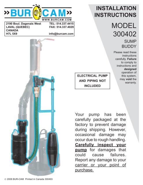
WWW.BURCAM.COM2190 Boul. Dagenais West TEL: 514.337.4415LAVAL (QUEBEC) FAX: 514.337.4029CANADAH7L 5X9info@burcam.comELECTRICAL PUMPAND PIPING NOTINCLUDEDINSTALLATIONINSTRUCTIONS<strong>MODEL</strong><strong>300402</strong>SUMPBUDDYPlease read theseinstructionscarefully. Failureto comply toinstructions anddesignedoperation ofthis system,may void thewarranty.Your pump has beencarefully packaged at thefactory to prevent damageduring shipping. However,occasional damage mayoccur due to rough handling.Carefully inspect yourpump for damages thatcould cause failures.Report any damage to yourcarrier or your point ofpurchase. 2008 BUR-CAM Printed in Canada 300493
SAFETY INSTRUCTIONS:(applicable to your electrical primary pump)This fine pump that you have just purchased is designed from the latest in material andworkmanship.Before installation and operation, we recommend the following procedures:ABCDECHECK WITH YOUR LOCAL ELECTRICAL AND PLUMBING CODES TO ENSURE YOUCOMPLY WITH THE REGULATIONS. THESE CODES HAVE BEEN DESIGNED WITHYOUR SAFETY IN MIND. BE SURE YOU COMPLY WITH THEM.WE RECOMMEND THAT A SEPARATE CIRCUIT BE LEAD FROM THE HOME ELECTRI-CAL DISTRIBUTION PANEL PROPERLY PROTECTED WITH A FUSE OR A CIRCUITBREAKER. WE ALSO RECOMMEND THAT A GROUND FAULT CIRCUIT BE USED.CONSULT A LICENSED ELECTRICIAN FOR ALL WIRING.THE GROUND TERMINAL ON THE THREE PRONG PLUGS SHOULD NEVER BEREMOVED. THEY ARE SUPPLIED AND DESIGNED FOR YOUR PROTECTION.NEVER MAKE ADJUSTMENTS TO ANY ELECTRICAL APPLIANCE OR PRODUCT WITHTHE POWER CONNECTED. DO NOT ONLY UNSCREW THE FUSE OR TRIP THE BREAKER,REMOVE THE POWER PLUG FROM THE RECEPTACLE.ASSUMING THAT YOU HAVE A SUMP PIT LOCATED IN YOUR BASEMENT FLOOR...YOUR SUMP PIT SHOULD BE CONSTRUCTED FROM CONCRETE, BRICK, TILE ORMORE RECENTLY A SUMP BASIN MADE FROM PLASTIC AND/OR FIBERGLASS. THEMINIMUM SIZE OF YOUR SUMP PIT MUST BE 18” IN DIAMETER AND NO LESS THAN 25”DEEP. WHEN PIT IS READY, PROCEED TO NEXT STEP.Material required for emergency sump pump applicationPump installationMunicipal water source with a minimum of 40 PSI and a maximum of 60 PSI.A pressure reducer/regulator is required if you exceed the maximum of 60 PSI.Desired length of copper pipe and required fittings to link up municipal water source tosump buddy automatic valve.Teflon tape.Desired length of polyethylene pipe and T or Y fitting, to link up sump buddy dischargeto existing discharge of electrical sump pump.Tools2Screwdrivers, hacksaw to cut pipe, knife to assist in pipe cutting, round file to smooth pipeends, pipe wrench, adjustable wrench to tighten fittings, propane torch andwelding material.FOR INFORMATION TEL: 514.337.4415 FAX: 514.337.4029
APPLICATION This pump is designed to be connected toany existing conventional type sump pumpsystem, as an extra sump pump protection. CAPACITY AT 60 PSI(municipal water pressure):5’ 581 US GPH Friction loss10’ 317 US GPH in pipe15’ 158 US GPH not includedFEATURES Extra protection during power outage or in theevent of failure of conventional sump pump. Easy to connect to existing conventional sumppump discharge line. Automatic control valve activate the SUMPBUDDY. No electricity required. No battery required.INSTALLATION STEPS(see diagram on page 5)STEP 1We recommend that you install your SUMP BUDDY in a location where there is adequateroom for servicing at a later date. Discharge line should be made from ABS or PVC 1 1/4” ,1 1/2” or 2” pipe.We do not recommend to install flexible drain kit due to friction loss. Head capacity and/ordischarge flow will be reduce in a large proportion.Use teflon tape on all connections.Keep suction screen and ejector clean.Check regularly your SUMP BUDDY to ensure its proper operation. Remember that solids ordebris in water should be removed from the sump pit.STEP 2STEP 3STEP 4Remove electrical power of your existing conventional sump pump and verify that this sumppump is equipped with a check valve at pump discharge. If not, add a check valve beforecontinuing your installation. The sump pump check valve should be located at the primarypump discharge and installed below the “Y” fitting.Locate your SUMP BUDDY in an ideal position and cut the existing discharge line to installthe T or Y fitting. Cut the desired length of pipe to connect the discharge line from the checkvalve of the SUMP BUDDY to the T or Y fitting.Run this discharge line with fittings to adjust your SUMP BUDDY in vertical position.We recommend that the distance between the bottom of the SUMP BUDDY and the bottomof the sump pit be approximately 2”.Check valve requiredas per step 2.350353 1 ½”FOR INFORMATION TEL: 514.337.4415 FAX: 514.337.40293
STEP 5STEP 6STEP 7STEP 8Close municipal water supply. Run a supply line (not less than 1/2”, 3/4” recommended) to theideal position for an easy operation of the automatic control valve of the SUMP BUDDY.Install a ball valve near the pump area, to close water supply for servicing at a later date.Flush this new line, before next step, to remove any debris which may obstruct the water flow inyour SUMP BUDDY.Screw the automatic control valve to the supply line.Install the 90 0 galvanized bracket to the automatic control valve by using the two screwssupplied.STEP 9STEP 10STEP 11STEP 12Install the stainless steel rod by simplyscrewing the two parts together. Using thelarge coupling, secure the rod connection.The top screw is to secure the top part andthe bottom screw is to secure the bottom partof the rod.The next step is to install the float by simplypassing the rod throught the float opening. Thenuse the small couplings to secure the float to therod by simply screwing the unit to the rod.The float should be set at least 2” higher thanthe conventional electrical pump setting, so thatthe back-up pump will not start prior to the mainelectrical pump. To complete the float installation,simply insert the stainless steel rodthrought the 90 0 bracket, then install a rubbergrommet below the control valve level, theninsert the shaft throught the control valve andinsert the second grommet on the top, then setthe grommet adjustement to the proper locationto properly adjust the setting.Fix the vacuum breaker to the automaticcontrol valve and screw the connecting hose.STEP 10STEP 11STEP 8 STEP 9STEP 13STEP 14STEP 15Adjust the length of the connecting hose and fix it to the sump buddy with a clamp.You are now ready to test your SUMP BUDDY. Restart municipal water supply, and confirm thatthere are no leaks in supply line. Try the automatic control valve by drawing up the lever. Waterwill go through the SUMP BUDDY. Push down the lever to shut off water flow.Fill the sump pit with water. Verify the action of the automatic control valve and the level of waterto start your SUMP BUDDY, then repeat the operation many times.STEP 164Turn on electrical power of the conventionnal sump pump and verify the entire system.FOR INFORMATION TEL: 514.337.4415 FAX: 514.337.4029
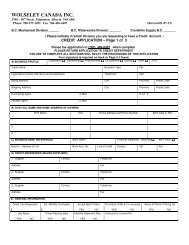
STEP 1Install with soliddischarge line from1 1/4” to 2” pipesize.TYPICAL INSTALLATION DIAGRAMFOR SUMP PUMPSTEP 6Flush line toremove debris.STEP 5Run a supply linewith a ball valvenear pump area.STEP 3Install T or Y fittingand link dischargelines together.STEP 11Install float and rodto automatic valve.STEP 7Screw automaticcontrol valve.This ejector ispress fit fixed.Do not try tounscrew, you willdamage and voidwarranty.Please call us tomake maintenaceat 1-800 361-1820.STEP 12Fix vacuumbreaker.STEP 8Install the floatbracket.STEP 9Assemble float rod.STEP 4Adjust in verticalposition and leave2” under SUMPBUDDY.STEP 2Remove electricalpower and verifyfor check valve.STEP 10Install float.2”STEP 13Adjust length ofconnecting hose.STEP 14Test manuallyautomatic controlvalve operation.STEP 15Fill pit with water.Verify automatic actionand starting level.STEP 16Turn on electricalpower of conventionalsump pump.FOR INFORMATION TEL: 514.337.4415 FAX: 514.337.40295
STEP 1Install with soliddischarge line from1 1/4” to 2” pipesize.TYPICAL INSTALLATION DIAGRAMFOR COLUMN PUMPSTEP 6Flush line toremove debris.STEP 5Run a supply linewith a ball valvenear pump area.STEP 3Install T or Y fittingand link dischargelines together.STEP 11Install float and rodto automatic valve.STEP 7Screw automaticcontrol valve.This ejector ispress fit fixed.Do not try tounscrew, you willdamage and voidwarranty.Please call us tomake maintenaceat 1-800 361-1820.STEP 12Fix vacuumbreaker.STEP 8Install the floatbracket.STEP 4Adjust in verticalposition and leave2” under SUMPBUDDY.STEP 9Assemble float rod.STEP 2Remove electricalpower and verifyfor check valve.2”STEP 10Install float.STEP 13Adjust length ofconnecting hose.STEP 14Test manuallyautomatic controlvalve operation.STEP 15Fill pit with water.Verify automatic actionand starting level.STEP 16Turn on electricalpower of conventionalsump pump.FOR INFORMATION TEL: 514.337.4415 FAX: 514.337.40296
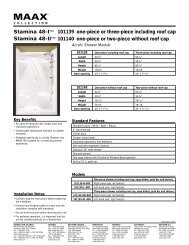
REPAIR PARTS LISTREF. PART DESCRIPTION1 350250 Pump body2 350254K Ejector kit (incl.#3, 4,5,6)3 350255 Ejector seal4 350254 Ejector5 350256 Ejector “O” ring6 350257 Ejector “O” ring7 350353A ABS check valve 1 1/4”8 350253 Coupling9 350252 Hose clamp10 350251 Connecting hose11 350260 Back flow preventorREF. PART DESCRIPTION12 350267 Automatic valve & bracket13 350248 Screws14 350247 90 0 float guide15 350246 Rubber stop16 350245 Stainl. steel float rod17 350244 Connection screws (2)18 350243 Adjustment couplings (2)19 350266 Float20 350241 Rod coupling21 350242 Screws (4) for rod22 350265 Float/valve assembly(incl. # 11 to 21)224712 153251361416811211019201718197REPAIR PARTS MAY BE ORDERED FROM YOUR AUTHORIZEDPOINT OF SALE OR FROM BUR-CAM PUMPS
TROUBLE SHOOTING GUIDE CHECKLISTNEVER MAKE ADJUSTMENTS TO ANY ELECTRICAL APPLIANCE OR PRODUCT WITH THE POWERCONNECTED. DON’T JUST UNSCREW THE FUSE OR TRIP THE BREAKER, REMOVE THE POWERFROM THE RECEPTACLE.TROUBLE PROBABLE CAUSEACTIONNo water isdrawn out.Municipal water supply closed.Automatic valve closed.Float do not rise with water level.Suction or ejector clogged.Water level below suction in sump.Improper function or missing check valvein primary pump discharge.Discharge line clogged.Pumping height more than 15 ft.Municipal water pressure under 40 PSI.Turn on ball valve.Check manually the valve operation.Check for obstruction of float action.Clean.Adjust the float rod to shut off pump priorto low water level.Install a check valve below the “Y” fittingon your primary pump discharge base.Check all pipes.Reduce top lift to less than 15 ft.head.Run a 3/4” direct line from municipal watersupply to reduce friction loss in pipe.Pump does notpump water tofull capacity.Municipal water supply partially opened.Automatic valve partially opened.Suction or ejector partially clogged.Leaky primary pump check valve.Discharge line partially clogged.Turn on ball valve.Check manually the valve operation.Clean.Replace.Check all pipes.Pump does notshut off.Automatic valve does not shut off.Float is obstructedCheck manually the valve operation.Check for obstruction oradjust rubber grommet to proper off andon position.TO THE END CONSUMERIf you have any problems with the product, before advising the store, where you’vepurchased the pump, please contact us at 514 337-4415 , and ask for our salesdepartment, and they will be pleased to help you with any questions you might have,concerning your installation.FOR INFORMATION TEL: 514.337.4415 FAX: 514.337.40298
WWW.BURCAM.COM2190 Boul. Dagenais Ouest TEL: 514.337.4415LAVAL (QUÉBEC) FAX: 514.337.4029CANADAH7L 5X9info@burcam.comINSTRUCTIONSD’INSTALLATIONPOMPEÉLECTRIQUE ETTUYAUTERIENON-INCLUSESMODÈLE<strong>300402</strong>LASENTINELLES’il vous plaît,veuillez lireattentivement cesinstructions. Ledéfaut de voussoumettre auxinstructions etopérationsappropriées àce systèmepeut annulerla garantie.Votre pompe a étésoigneusement emballée àl’usine, pour prévenir lesdommages possibles lors dutransport. Toutefois, desdommages occasionnelspeuvent être encourus parune mauvaise manutention.Vérifiez soigneusementvotre pompe afin de décelertout dommage possible quipourrait causer un bris dela pompe. Signalez toutdommage au transporteur ouà votre point de vente.© 2008 BUR-CAM Imprimé au Canada 300493
CONSEILS DE SÉCURITÉ:(applicable à la pompe primaire électrique)La pompe que vous venez d’acquérir est un produit fabriqué avec les meilleurs matériauxet par une main-d’oeuvre spécialisée.Veuillez suivre les instructions d’utilisation et prendre les précautions nécessaires pourvotre sécurité:ABCDECONSULTEZ LES NORMES DE PLOMBERIE ET D’ÉLECTRICITÉ SE RAPPORTANT ÀVOTRE RÉGION, POUR VOUS ASSURER DES RÈGLES À RESPECTER. CES CODESSONT ÉTABLIS POUR VOTRE SÉCURITÉ. VEUILLEZ LES RESPECTER.NOUS RECOMMANDONS QU’UN CIRCUIT ÉLECTRIQUE SOIT INSTALLÉ DU PANNEAUDE DISTRIBUTION DE VOTRE MAISON, ET PROTÉGÉ PAR UN FUSIBLE OU UNCOUPE-CIRCUIT (DISJONCTEUR). UN CIRCUIT DE PROTECTION AVEC MISE À TERREEST RECOMMANDÉ. CONSULTEZ UN ÉLECTRICIEN LICENCIÉ.LE TERMINAL DE LA MISE À TERRE DE VOTRE PRISE DE COURANT NE DOIT JAMAISÊTRE ENLEVÉ. IL EST FOURNI ET CONÇU POUR VOTRE SÉCURITÉ.LORS D’AJUSTEMENT SUR DES APPAREILS ÉLECTRIQUES, TOUJOURS S’ASSURERQUE LE COURANT EST DÉBRANCHÉ. NE PAS SEULEMENT ENLEVER LE FUSIBLE OUMETTRE LE DISJONCTEUR HORS TENSION. IL FAUT DÉBRANCHER LE CÂBLED’ALIMENTATION DE LA PRISE.ASSUMANT QUE VOUS AVEZ UNE FOSSE DANS VOTRE SOUS-SOL... VOTRE FOSSEDOIT ÊTRE CONSTRUITE DE BÉTON, BRIQUES, TUILES OU BASSIN DE PLASTIQUEET/OU DE FIBRE DE VERRE. LA DIMENSION MINIMALE DE LA FOSSE DOIT ÊTRE DE 18”DE DIAMÈTRE PAR 25” DE PROFONDEUR. LORSQUE LA FOSSE EST CONFORME,PASSER À L’ÉTAPE SUIVANTE.Matériel requis pour la pompe puisard d’urgenceInstallation de la pompe- Alimentation d’eau de l’aqueduc municipal, à une pression minimale de 40 lb./po. 2 et maximalde 60 PSI. Un régulateur de pression est requis si la pression excède 60 lb./po. 2- Longueur nécessaire de tuyau de cuivre et adaptateurs requis pour relier la source d’eaumunicipale à la valve automatique de LA SENTINELLE.- Ruban téflon.- Longueur nécessaire de tuyau de polyéthylène et d’adaptateur en T ou en Y, pour relier ladécharge de LA SENTINELLE à la décharge de la pompe puisard électrique existante.Outils2- Tournevis, scie à métaux pour couper les tuyaux, couteaux pour aider à la coupe destuyaux, lime ronde pour nettoyer les bouts des tuyaux, clé à tuyau, clé à molette ajustable,torche au propane et matériel de soudage.POUR INFORMATION TEL: 514.337.4415 FAX: 514.337.4029
APPLICATION Cette pompe a été conçue pour être raccordéeà tout type de pompe puisard existante,comme protection supplémentaire. CAPACITÉ À 60 LB./PO 2(pression municipale):5’ 581 GPH US Pertes dûes10’ 317 GPH US à la friction15’ 158 GPH US non-inclusesCARACTÉRISTIQUES Protection supplémentaire lors d’un arrêt decourant ou dans l’éventualité d’une pannede la pompe puisard conventionnelle. Se branche facilement à la décharge de lapompe conventionnelle. Activation par valve de contrôle automatique . Aucune alimentation électrique requise. Aucune batterie requise.Étape 1ÉTAPES D’INSTALLATION(voir le diagramme à la page 5)Nous recommandons que LA SENTINELLE soit installée dans un endroit où l’espace de travailsera suffisant pour tout service ultérieur. La ligne de décharge doit être de 1 1/4”,1 1/2” ou 2”, en ABS ou PVC.En raison de la perte due à la friction, nous déconseillons l’installation d’un boyau dedrainage flexible.Utilisez du ruban téflon pour assurer l’étanchéité de tous les branchements vissés.Maintenez le grillage de suction et l’injecteur bien propres.Vérifiez régulièrement LA SENTINELLE pour vous assurer de son bon fonctionnement.N’oubliez pas d’enlever les matières solides et les débris.Étape 2Étape 3Étape 4Débranchez l’alimentation électrique de la pompe puisard conventionnelle et vérifiez qu’elleest munie d’un clapet de retenue à la décharge. Dans la négative, installez-y un clapet avantde continuer l’installation, assurez vous qu’il doit être installé sous le raccord en “Y” duconduit de refoulement.Localisez la position idéale de LA SENTINELLE et coupez la ligne de décharge existantepour y fixer l’embranchement en T ou en Y. Coupez la longueur de tuyau requise et raccordezla décharge du clapet de retenue de LA SENTINELLE au T ou au Y.Installez la ligne de décharge avec les raccords requis pour aligner LA SENTINELLE dansune position verticale. Nous recommandons que la distance entre la base du puisard et ledessous de LA SENTINELLE soit d’environ 2”.Clapet de retenue tel querecommandé à l’étape 2.350353 1 ½”POUR INFORMATION TEL: 514.337.4415 FAX: 514.337.40293
Étape 5Étape 6Étape 7Étape 8Étape 9Étape 10Coupez l’alimentation d’eau municipale. Installez une ligne de service (minimum 1/2”, 3/4”recommandé) pour raccorder, à une position de fonctionnement idéale, la valve de contrôleautomatique de LA SENTINELLE. Installez une valve à bille près de la pompe pour permettred’enlever rapidement l’alimentation en eau, si besoin ultérieur.Vidangez la nouvelle ligne, avant la prochaine étape, pour enlever tout débris qui pourraitobstruer le débit d’eau dans LA SENTINELLE.Vissez la valve de contrôle automatique à la nouvelle ligne d’eau municipale.Vissez le support de flotte (90 0 ) à la valve automatique à l’aide des vis incluses.Vissez ensemble les deux pièces de la tige de la flotte. Bloquez le joint à l’aide del’accouplement inclus. La vis du haut bloque la partie supérieure et la vis du bas verrouille lapartie inférieure.L’étape suivante consiste à insérer le boutinférieur de la tige dans la flotte et de lebloquer à l’aide des deux accouplements.Étape 11Étape 12Étape 13La flotte doit être ajustée pour un démarrageà un niveau supérieur de 2” du niveau dedémarrage de la pompe électrique. Pourcompléter l’installation, insérez la tige dansle support (90 0 ), puis dans le levier de lavalve, en prenant soin d’insérer les butoirsde caoutchouc sur la tige, sous et au-dessusdu levier. Ajustez ces derniers pour uneopération adéquate.Fixez l’anti-siphon à la sortie de la valveautomatique de contrôle et vissez-y leboyau.Ajustez la longueur du boyau et fixez-le àLA SENTINELLE au moyen du collet deserrage.Étape 10Étape 11Étape 8 Étape 9Étape 14Étape 15Vérifiez le fonctionnement de LASENTINELLE. Démarrez l’alimentationd’eau municipale et assurez-vous qu’il n’y apas de fuite. Essayez la valve de contrôleautomatique en soulevant le levier. L’eau va s’insérer dans LA SENTINELLE. Abaissez lelevier pour couper l’eau.Emplissez le puisard avec de l’eau. Vérifiez l’action de la valve de contrôle automatique etle niveau d’eau au démarrage. Répétez l’opération à quelques reprises.Étape 164Branchez l’alimentation électrique de la pompe conventionnelle et vérifiez tout le système.POUR INFORMATION TEL: 514.337.4415 FAX: 514.337.4029
ÉTAPE 1Installez une lignede décharge rigide.Tuyau de 1 1/4”à 2”.ÉTAPE 3Installez le raccorden T ou en Y etreliez les lignes.DIAGRAMME D’INSTALLATION TYPIQUEPOUR POMPE SUBMERSIBLEÉTAPE 6Nettoyez la ligne pourenlever les débris.ETAPE 5Faite une ligned’alimentation munied’une valve à bille.ETAPE 11Installez la tige et laflotte à la valveautomatique.ÉTAPE 7Vissez la valve decontrôle automatique.Cet éjecteur est insérésous pression à notreusine. Essayer de ledévisser pourraitl’endommager etannuler la garantie.Contactez nous pourson entretien, au :1-800 361-1820.ÉTAPE 12Fixez l’anti-siphon.ÉTAPE 8Installez le support.ÉTAPE 9Assemblez la tige.ÉTAPE 4Alignez en positionverticale et laissez2” sous LASENTINELLE.ÉTAPE 2Enlevez l’alimentationélectrique etvérifiez pour leclapet de retenue.2”ÉTAPE 10Assemblez la flotte.ÉTAPE 13Ajustez la longueurdu boyau.ÉTAPE 14Essayez manuellementla valve de contrôleautomatique.ÉTAPE 15Remplissez le puisard.Vérifiez la fonctionautomatique et le niveaudedémarrage.ÉTAPE 16Rebranchez l’alimentationélectrique de la pompeconventionnelle.POUR INFORMATION TEL: 514.337.4415 FAX: 514.337.40295
DIAGRAMME D’INSTALLATION TYPIQUEPOUR POMPE À COLONNEÉTAPE 1Installez une ligne dedécharge rigide.Tuyau de 1 1/4” à 2”.ÉTAPE 6Nettoyez la ligne pourenlever les débris.ETAPE 5Faite une ligned’alimentation munied’une valve à bille.ÉTAPE 3Installez le raccorden T ou en Y etreliez les lignes.ETAPE 11Installez la tige et laflotte à la valveautomatique.Cet éjecteur estinséré sous pressionà notre usine.Essayer de ledévisser pourraitl’endommager etannuler la garantie.Contactez nous pourson entretien, au :1-800 361-1820ÉTAPE 7Vissez la valve decontrôle automatique.ÉTAPE 12Fixez l’anti-siphon.ÉTAPE 8Ajustez le support.ÉTAPE 4Alignez en positionverticale et laissez2” sous LASENTINELLE.ÉTAPE 9Assemblez la tige.2”ÉTAPE 2Enlevez l’alimentationélectrique etvérifiez pour leclapet de retenue.ETAPE 10Installer la flotte6ÉTAPE 13Ajustez la longueurdu boyau.ÉTAPE 14Essayez manuellementla valve de contrôleautomatique.ÉTAPE 15Remplissez le puisard.Vérifiez la fonctionautomatique et le niveaudedémarrage.ÉTAPE 16Rebranchez l’alimentationélectrique de la pompeconventionnelle.POUR INFORMATION TEL: 514.337.4415 FAX: 514.337.4029
PIÈCES DE REMPLACEMENTREF. PIÈCES DESCRIPTION1 350250 Boîtier de la pompe2 350254K Trousse de l’éjecteur(incl.#3,4, 5,6)3 350255 Sceau de l’éjecteur4 350254 Ejecteur5 350256 Joint torique de l’éjecteur6 350257 Joint torique de l’éjecteur7 350353A Clapet de retenue en ABS 1 1/4”8 350253 Raccord9 350252 Collet du boyau10 350251 Boyau11 350260 AntiretourREF. PIÈCES DESCRIPTION12 350267 Valve automatique et support13 350248 Vis14 350247 90 0 guide de flotte15 350246 Arrêt en caoutchouc16 350245 Tige du flotteur en acier inox.17 350244 Vis de connexion (2)18 350243 Bagues de réglage (2)19 350266 Flotte20 350241 Bague d’accouplement21 350242 Vis de la tige(4)22 350265 Ensemblage valve et flotte(incl. #11 à 21)224712 15325136141681121101920171819LES PIÈCES DE RECHANGE PEUVENT ÊTRE ACQUISES DE VOTREPOINT DE VENTE AUTORISÉ OU DE POMPES BUR-CAM.7
GUIDE DE RÉSOLUTION DES PROBLÈMESLORS D’AJUSTEMENT SUR DES APPAREILS ÉLECTRIQUES, TOUJOURS S’ASSURER QUELE COURANT EST DÉBRANCHÉ. NE PAS SEULEMENT ENLEVER LE FUSIBLE OU METTRE LEDISJONCTEUR HORS TENSION. IL FAUT DÉBRANCHER LE CÂBLE D’ALIMENTATION DE LA PRISE.PROBLÈME CAUSE PROBABLEACTIONL’eau n’est pasaspirée.L’alimentation municipale est fermée.La valve automatique est fermée.La flotte ne s’éleve pas avec le niveaud’eau.Grille de succion ou injecteur bloqué.Le niveau d’eau du puisard est sous leniveau de succion.Fonctionnement inadéquat ou absence declapet de retenue à la pompe principale.Ligne de décharge bloquée.Ligne de décharge supérieure à 15’.Pression d’eau municipale sous 40 LPC.Ouvrir la valve à bille.Vérifier manuellement la valve.Vérifier s’il y a des obstacles à l’actionverticale de la flotte.Nettoyer.Ajuster la tige de la flotte pour arrêter lapompe avant le bas niveau.Installer un clapet de retenue sous leraccord en “Y” du conduit de refoulementde la pompe primaire.Vérifier la tuyauterie.Réduire la hauteur sous 15’.Installer une ligne d’alimentation directed’eau municipale de 3/4”, pour réduire laperte de friction.L’eau n’est pasaspirée àpleine capacité.L’alimentation d’eau municipale estpartiellement ouverte.Valve automatique partiellement ouverte.Succion ou injecteur partiellement obstrué.Fuite au clapet de retenue de la pompeprimaire.Ligne de décharge partiellement obstruée.Ouvrir la valve à bille.Vérifier manuellement la valve.Nettoyer.Remplacer.Vérifier la tuyauterie.La pompen’arrête pas.La valve automatique ne s’arrête pas.Le mouvement vertical de la flotte, avec leniveau d’eau, est obstrué.Vérifier manuellement la valve.Vérifier s’il y a des obstacles à l’actionverticale de la pesée ouajuster les butoirs de caoutchouc.8AU CONSOMMATEURSi vous connaissez des problèmes avec ce produit, avant d’appeler le magasin oùvous en avez fait l’acquisition, s’il-vous-plaît, contactez notre service à la clientèleau 514 337-4415. Ils se feront un plaisir de vous aider avec toutes les questionsque vous auriez concernant l’installation.POUR INFORMATION TEL: 514.337.4415 FAX: 514.337.4029