Bruciatori di gasolio Ölbrenner Light oil burners Brûleurs à fioul ...
Bruciatori di gasolio Ölbrenner Light oil burners Brûleurs à fioul ...
Bruciatori di gasolio Ölbrenner Light oil burners Brûleurs à fioul ...

You also want an ePaper? Increase the reach of your titles
YUMPU automatically turns print PDFs into web optimized ePapers that Google loves.
Istruzioni per installazione, uso e manutenzioneAnleitungen für Einbau, Betrieb und WartungInstallation, use and maintenance instructionsInstructions pour installation, utilisation et entretienIDGBF<strong>Bruciatori</strong> <strong>di</strong> <strong>gasolio</strong><strong>Ölbrenner</strong><strong>Light</strong> <strong>oil</strong> <strong>burners</strong><strong>Brûleurs</strong> <strong>à</strong> <strong>fioul</strong> domestiqueFunzionamento bista<strong>di</strong>oZweistufiger BetriebTwo-stage operationFonctionnement <strong>à</strong> deux alluresCODICE - CODEMODELLO - MODELLMODEL - MODELETIPO - TYPTYPE - TYPE3475611 RL 190 673 T12915640 (4)
IINDICEDINHALTDATI TECNICI . . . . . . . . . . . . . . . . . . . . . . . . . . . . . . . . . pagina 4Descrizione bruciatore . . . . . . . . . . . . . . . . . . . . . . . . . . . . . . . . . 8Imballo - Peso . . . . . . . . . . . . . . . . . . . . . . . . . . . . . . . . . . . . . . . 8Ingombro . . . . . . . . . . . . . . . . . . . . . . . . . . . . . . . . . . . . . . . . . . . 8Corredo . . . . . . . . . . . . . . . . . . . . . . . . . . . . . . . . . . . . . . . . . . . . 8Campo <strong>di</strong> lavoro . . . . . . . . . . . . . . . . . . . . . . . . . . . . . . . . . . . . . 10Caldaia <strong>di</strong> prova . . . . . . . . . . . . . . . . . . . . . . . . . . . . . . . . . . . . . 10INSTALLAZIONE. . . . . . . . . . . . . . . . . . . . . . . . . . . . . . . . . . . . 10Piastra caldaia . . . . . . . . . . . . . . . . . . . . . . . . . . . . . . . . . . . . . . 10Lunghezza boccaglio . . . . . . . . . . . . . . . . . . . . . . . . . . . . . . . . . 10Fissaggio del bruciatore alla caldaia . . . . . . . . . . . . . . . . . . . . . 10Scelta degli ugelli per 1° e 2° sta<strong>di</strong>o. . . . . . . . . . . . . . . . . . . . . . 12Montaggio degli ugelli. . . . . . . . . . . . . . . . . . . . . . . . . . . . . . . . . 12Regolazione testa <strong>di</strong> combustione . . . . . . . . . . . . . . . . . . . . . . . 12Impianto idraulico . . . . . . . . . . . . . . . . . . . . . . . . . . . . . . . . . . . . 14Impianto elettrico . . . . . . . . . . . . . . . . . . . . . . . . . . . . . . . . . . . . 16Pompa . . . . . . . . . . . . . . . . . . . . . . . . . . . . . . . . . . . . . . . . . . . . 20Regolazione bruciatore . . . . . . . . . . . . . . . . . . . . . . . . . . . . . . . 22Funzionamento bruciatore . . . . . . . . . . . . . . . . . . . . . . . . . . . . . 24Controlli finali . . . . . . . . . . . . . . . . . . . . . . . . . . . . . . . . . . . . . . . 26Manutenzione. . . . . . . . . . . . . . . . . . . . . . . . . . . . . . . . . . . . . . . 26STATUS . . . . . . . . . . . . . . . . . . . . . . . . . . . . . . . . . . . . . . . . . . . 28Inconvenienti - Cause - Rime<strong>di</strong> . . . . . . . . . . . . . . . . . . . . . . . . . 30AvvertenzaLe figure richiamate nel testo sono così in<strong>di</strong>cate:1)(A) = Particolare 1 della figura A nella stessa pagina del testo;1)(A)p.4 = Particolare 1 della figura A riportata a pagina 4.TECHNISCHE ANGABEN . . . . . . . . . . . . . . . . . . . . . . . . . Seite 5Brennerbeschreibung . . . . . . . . . . . . . . . . . . . . . . . . . . . . . . . . . . 9Verpackung - Gewicht . . . . . . . . . . . . . . . . . . . . . . . . . . . . . . . . . . 9Abmessungen . . . . . . . . . . . . . . . . . . . . . . . . . . . . . . . . . . . . . . . . 9Ausstattung . . . . . . . . . . . . . . . . . . . . . . . . . . . . . . . . . . . . . . . . . . 9Regelbereich . . . . . . . . . . . . . . . . . . . . . . . . . . . . . . . . . . . . . . . . 11Prüfkessel . . . . . . . . . . . . . . . . . . . . . . . . . . . . . . . . . . . . . . . . . . 11INSTALLATION . . . . . . . . . . . . . . . . . . . . . . . . . . . . . . . . . . . . . 11Kesselplatte. . . . . . . . . . . . . . . . . . . . . . . . . . . . . . . . . . . . . . . . . 11Flammrohrlänge . . . . . . . . . . . . . . . . . . . . . . . . . . . . . . . . . . . . . 11Befestigung des Brenners am Heizkessel . . . . . . . . . . . . . . . . . 11Wahl der Düse für <strong>di</strong>e 1. und 2. Stufe . . . . . . . . . . . . . . . . . . . . 13Düsemontage . . . . . . . . . . . . . . . . . . . . . . . . . . . . . . . . . . . . . . . 13Einstellung des Flammkopfs . . . . . . . . . . . . . . . . . . . . . . . . . . . . 13Hydraulikanlage . . . . . . . . . . . . . . . . . . . . . . . . . . . . . . . . . . . . . 15Elektroanlage . . . . . . . . . . . . . . . . . . . . . . . . . . . . . . . . . . . . . . . 17Pumpe. . . . . . . . . . . . . . . . . . . . . . . . . . . . . . . . . . . . . . . . . . . . . 21Brennereinstellung . . . . . . . . . . . . . . . . . . . . . . . . . . . . . . . . . . . 23Brennerbetrieb . . . . . . . . . . . . . . . . . . . . . . . . . . . . . . . . . . . . . . 25Endkontrollen . . . . . . . . . . . . . . . . . . . . . . . . . . . . . . . . . . . . . . . 27Wartung. . . . . . . . . . . . . . . . . . . . . . . . . . . . . . . . . . . . . . . . . . . . 27STATUS. . . . . . . . . . . . . . . . . . . . . . . . . . . . . . . . . . . . . . . . . . . . 29Störungen - Ursachen - Abhilfen . . . . . . . . . . . . . . . . . . . . . . . . . 31AnmerkungDie Zeichnungen, auf <strong>di</strong>e im Text Bezug genommen wird, werdenfolgendermaßen bezeichnet:1)(A) =Detail 1 der Zeichnung A auf der gleichen Textseite;1)(A)p.4 =Detail 1 der Zeichnung A auf Seite 4.GBCONTENTSFINDEXTECHNICAL DATA . . . . . . . . . . . . . . . . . . . . . . . . . . . . . . .page 6Burner description . . . . . . . . . . . . . . . . . . . . . . . . . . . . . . . . . . . . 9Packaging - Weight . . . . . . . . . . . . . . . . . . . . . . . . . . . . . . . . . . . 9Max. <strong>di</strong>mensions . . . . . . . . . . . . . . . . . . . . . . . . . . . . . . . . . . . . . 9Standard equipment . . . . . . . . . . . . . . . . . . . . . . . . . . . . . . . . . . . 9Firing rate . . . . . . . . . . . . . . . . . . . . . . . . . . . . . . . . . . . . . . . . . . .11Test b<strong>oil</strong>er. . . . . . . . . . . . . . . . . . . . . . . . . . . . . . . . . . . . . . . . . . .11INSTALLATION . . . . . . . . . . . . . . . . . . . . . . . . . . . . . . . . . . . . . .11B<strong>oil</strong>er plate . . . . . . . . . . . . . . . . . . . . . . . . . . . . . . . . . . . . . . . . . .11Blast tube length . . . . . . . . . . . . . . . . . . . . . . . . . . . . . . . . . . . . .11Securing the burner to the b<strong>oil</strong>er . . . . . . . . . . . . . . . . . . . . . . . . .11Choice of nozzles for 1st and 2nd stage . . . . . . . . . . . . . . . . . . 13Nozzle assembly . . . . . . . . . . . . . . . . . . . . . . . . . . . . . . . . . . . . 13Combustion head setting . . . . . . . . . . . . . . . . . . . . . . . . . . . . . . 13Hydraulic system . . . . . . . . . . . . . . . . . . . . . . . . . . . . . . . . . . . . 15Electrical system . . . . . . . . . . . . . . . . . . . . . . . . . . . . . . . . . . . . 17Pump . . . . . . . . . . . . . . . . . . . . . . . . . . . . . . . . . . . . . . . . . . . . . 21Burner calibration . . . . . . . . . . . . . . . . . . . . . . . . . . . . . . . . . . . . 23Burner operation. . . . . . . . . . . . . . . . . . . . . . . . . . . . . . . . . . . . . 25Final checks . . . . . . . . . . . . . . . . . . . . . . . . . . . . . . . . . . . . . . . . 27Maintenance. . . . . . . . . . . . . . . . . . . . . . . . . . . . . . . . . . . . . . . . 27STATUS . . . . . . . . . . . . . . . . . . . . . . . . . . . . . . . . . . . . . . . . . . . 29Fault - Probable cause - Suggested remedy . . . . . . . . . . . . . . . 32N.B.Figures mentioned in the text are identified as follows:1)(A) = part 1 of figure A, same page as text;1)(A)p.4 = part 1 of figure A, page number 4.DONNÉES TECHNIQUES . . . . . . . . . . . . . . . . . . . . . . . . . page 7Description brûleur . . . . . . . . . . . . . . . . . . . . . . . . . . . . . . . . . . . . 9Emballage - Poids . . . . . . . . . . . . . . . . . . . . . . . . . . . . . . . . . . . . . 9Encombrement . . . . . . . . . . . . . . . . . . . . . . . . . . . . . . . . . . . . . . . 9Equipement standard . . . . . . . . . . . . . . . . . . . . . . . . . . . . . . . . . . 9Plage de puissance. . . . . . . . . . . . . . . . . . . . . . . . . . . . . . . . . . . 11Chau<strong>di</strong>ère d’essai . . . . . . . . . . . . . . . . . . . . . . . . . . . . . . . . . . . . 11INSTALLATION . . . . . . . . . . . . . . . . . . . . . . . . . . . . . . . . . . . . . 11Plaque chau<strong>di</strong>ère . . . . . . . . . . . . . . . . . . . . . . . . . . . . . . . . . . . . 11Longueur buse . . . . . . . . . . . . . . . . . . . . . . . . . . . . . . . . . . . . . . 11Fixation du brûleur <strong>à</strong> la chau<strong>di</strong>ère. . . . . . . . . . . . . . . . . . . . . . . . 11Choix des gicleurs pour la 1ère et 2ème allure. . . . . . . . . . . . . . 13Montage du gicleur . . . . . . . . . . . . . . . . . . . . . . . . . . . . . . . . . . . 13Réglage tête de combustion . . . . . . . . . . . . . . . . . . . . . . . . . . . . 13Installation hydraulique . . . . . . . . . . . . . . . . . . . . . . . . . . . . . . . . 15Installation électrique . . . . . . . . . . . . . . . . . . . . . . . . . . . . . . . . . 17Pompe. . . . . . . . . . . . . . . . . . . . . . . . . . . . . . . . . . . . . . . . . . . . . 21Réglage brûleur. . . . . . . . . . . . . . . . . . . . . . . . . . . . . . . . . . . . . . 23Fonctionnement brûleur . . . . . . . . . . . . . . . . . . . . . . . . . . . . . . . 25Contrôles finaux . . . . . . . . . . . . . . . . . . . . . . . . . . . . . . . . . . . . . 27Entretien . . . . . . . . . . . . . . . . . . . . . . . . . . . . . . . . . . . . . . . . . . . 27STATUS. . . . . . . . . . . . . . . . . . . . . . . . . . . . . . . . . . . . . . . . . . . . 29Inconvénients - Causes - Remèdes . . . . . . . . . . . . . . . . . . . . . . 33AttentionLes figures rappelées dans le texte sont comme suit in<strong>di</strong>quées:1)(A) =Détail 1 de la figure A dans la même page du texte;1)(A)p.4 =Détail 1 de la figure A page 4.3
DATI TECNICIIMODELLO RL 190TIPO673 T1POTENZA (1)sta<strong>di</strong>o 2° kW 1423 - 2443PORTATA (1) Mcal/hkg/h1224 - 2100120 - 206sta<strong>di</strong>o 1° kW 759 - 1423Mcal/hkg/h653 - 122464 - 120COMBUSTIBILEGASOLIO- potere calorifico inferiore kWh/kgMcal/kg11,810,2 (10.200 kcal/kg)- densit<strong>à</strong> kg/dm 3 0,82 - 0,85- viscosit<strong>à</strong> a 20 °C mm 2 /s max 6 (1,5 °E - 6 cSt)FUNZIONAMENTO• Intermittente (min. 1 arresto ogni 24 ore).• Bista<strong>di</strong>o (alta e bassa fiamma) e monosta<strong>di</strong>o (tutto - niente).UGELLI numero 2IMPIEGO STANDARDCaldaie: ad acqua, a vapore, ad olio <strong>di</strong>atermicoTEMPERATURA AMBIENTE °C 0 - 40TEMPERATURA ARIA COMBURENTE °C max 60ALIMENTAZIONE ELETTRICAVHz230 - 400 con neutro ~ +/-10%50 - trifaseMOTORE ELETTRICOrpmWV28004500220/240 - 380/415Corrente <strong>di</strong> funzionamento A 15,8 - 9,1Corrente <strong>di</strong> spunto A 126 - 72,8TRASFORMATORE D’ACCENSIONEV1 - V2I1 - I2230 V - 2 x 5 kV1,9 A - 35 mAAPPARECCHIATURA ELETTRICA RBO 522POMPA J7Cportata (a 12 bar)campo <strong>di</strong> pressionetemperatura combustibilekg/hbar° C max23010 - 2190POTENZA ELETTRICA ASSORBITA W max 5870GRADO DI PROTEZIONE IP 44CONFORMITÀ DIRETTIVE CEE 89/336 - 73/23 - 89/392RUMOROSITÀ (2) dBA 83,9OMOLOGAZIONE DIN 5G861/03(1) Con<strong>di</strong>zioni <strong>di</strong> riferimento: Temperatura ambiente 20°C - Pressione barometrica 1000 mbar - Altitu<strong>di</strong>ne 100 m s.l.m.(2) Pressione sonora misurata nel laboratorio combustione del costruttore, con bruciatore funzionante su caldaia <strong>di</strong> prova, alla potenza massima.4
TECHNISCHE ANGABENDMODELL RL 190TYP673 T1LEISTUNG (1)2. Stufe kW 1423 - 2443DURCHSATZ (1) Mcal/hkg/h1224 - 2100120 - 2061. Stufe kW 759 - 1423Mcal/hkg/h653 - 122464 - 120BRENNSTOFFHEIZÖL EL- Heizwert Hu kWh/kgMcal/kg11,810,2 (10.200 kcal/kg)- Dichte kg/dm 3 0,82 - 0,85- Viskosität bei 20 °C mm 2 /s max 6 (1,5 °E - 6 cSt)BETRIEB• Aussetzend (min. 1 Halt in 24 Std).• Zweistufig (hohe und niedrige Flamme) - einstufig (alles - nichts).DÜSEN Stück 2STANDARDEINSATZHeizkessel: mit Wasser, Dampf, <strong>di</strong>athermischem ÖlRAUMTEMPERATUR °C 0 - 40TEMPERATUR VERBRENNUNGSLUFT °C max 60ELEKTRISCHE SPEISUNGVHz230 - 400 mit Nulleiter ~ +/-10%50 - dreiphasigELEKTROMOTOR(1) Bezugsbe<strong>di</strong>ngungen: Raumtemperatur 20°C - Barometrischer Druck 1000 mbar - Höhe 100 m ü.d.M.(2) Schalldruck, im Brennprüflabor des Herstellers mit Brenner auf Prüfkessel bei Höchstleistung gemessen.rpmWV28004500220/240 - 380/415Betriebsstrom A 15,8 - 9,1Anlaßstrom A 126 - 72,8ZÜNDTRANSFORMATORV1 - V2I1 - I2230 V - 2 x 5 kV1,9 A - 35 mASTEUERGERÄT RBO 522PUMPE J7CFördermenge (bei 12 bar)DruckbereichBrennstofftemperaturkg/hbar° C max23010 - 2190ELEKTRISCHE LEISTUNGSAUFNAHME W max 5870SCHUTZART IP 44CE-NORMGERECHT 89/336 - 73/23 - 89/392SCHALLDRUCKPEGEL (2) dBA 83,9ZULASSUNGEN DIN 5G861/035
TECHNICAL DATAGBMODEL RL 190TYPE673 T1OUTPUT (1)2nd stage kW 1423 - 2443DELIVERY (1) Mcal/hkg/h1224 - 2100120 - 2061st stage kW 759 - 1423Mcal/hkg/h653 - 122464 - 120FUELLIGHT OIL- net calorific value kWh/kgMcal/kg11.810.2 (10.200 kcal/kg)- density kg/dm 3 0.82 - 0.85- viscosity at 20 °C mm 2 /s max 6 (1.5 °E - 6 cSt)OPERATION• Intermittent (min. 1 stop in 24 hours).• Two-stage (high and low flame) and single-stage (all - nothing)NOZZLES number 2STANDARD APPLICATIONSB<strong>oil</strong>ers: water, steam, <strong>di</strong>athermic <strong>oil</strong>AMBIENT TEMPERATURE °C 0 - 40COMBUSTION AIR TEMPERATURE °C max 60ELECTRICAL SUPPLYVHz230 - 400 with neutral +/-10%50 - three-phase ~ELECTRIC MOTORrpmWV28004500220/240 - 380/415Running current A 15.8 - 9.1Start-up current A 126 - 72.8IGNITION TRANSFORMERV1 - V2I1 - I2230 V - 2 x 5 kV1,9 A - 35 mACONTROL BOX RBO 522PUMP J7Cdelivery (at 12 bar)pressure rangefuel temperaturekg/hbar° C max23010 - 2190ELECTRICAL POWER CONSUMPTION W max 5870ELECTRICAL PROTECTION IP 44IN CONFORMITY WITH EEC DIRECTIVES 89/336 - 73/23 - 89/392NOISE LEVELS (2) dBA 83.9APPROVAL DIN 5G861/03(1) Reference con<strong>di</strong>tions: Ambient temperature 20°C - Barometric pressure 1000 mbar - Altitude 100 m a.s.l.(2) Sound pressure measured in manufacturer’s combustion laboratory, with burner operating on test b<strong>oil</strong>er and at maximum rated output.6
DONNEES TECHNIQUESFMODELE RL 190TYPE673 T1PUISSANCE (1)2ème allure kW 1423 - 2443DEBIT (1) Mcal/hkg/h1224 - 2100120 - 2061ère allure kW 759 - 1423Mcal/hkg/h653 - 122464 - 120COMBUSTIBLEFIOUL DOMESTIQUE- pouvoir calorifique inférieur kWh/kgMcal/kg11,810,2 (10.200 kcal/kg)- densité kg/dm 3 0,82 - 0,85- viscosité <strong>à</strong> 20 °C mm 2 /s max 6 (1,5 °E - 6 cSt)FONCTIONNEMENT• Intermittent (1 arrêt min en 24 heures).• 2 allures (flamme haute et basse) - et une allure (tout - rien)GICLEURS nombre 2EMPLOI STANDARDChau<strong>di</strong>ères <strong>à</strong> eau, <strong>à</strong> vapeur, <strong>à</strong> huile <strong>di</strong>athermiqueTEMPERATURE AMBIANTE °C 0 - 40TEMPERATURE AIR COMBURANT °C max 60ALIMENTATION ELECTRIQUEVHz230 - 400 avec neutre +/-10%50 - triphasée ~MOTEUR ELECTRIQUErpmWV28004500220/240 - 380/415Courant de fonctionnement A 15,8 - 9,1Courant de pointe A 126 - 72,8TRANSFORMATEUR D’ALLUMAGEV1 - V2I1 - I2230 V - 2 x 5 kV1,9 A - 35 mACOFFRET DE SÉCURITÉ RB0 522POMPE J7Cdébit (<strong>à</strong> 12 bar)plage de pressiontempérature combustiblekg/hbar° C max23010 - 2190PUISSANCE ELECTRIQUE ABSORBEE W max 5870DEGRE DE PROTECTION IP 44CONFORMÉMENT AUX DIRECTIVES CEE 89/336 - 73/23 - 89/392NIVEAU DE BRUIT (2) dBA 83,9HOMOLOGATION DIN 5G861/03(1) Con<strong>di</strong>tions de référence: Température ambiante 20°C - Pression barométrique 1000 mbar - Altitude 100 m au-dessus du niveau de la mer.(2) Pression acoustique mesurée dans le laboratoire combustion du constructeur, le brûleur fonctionnant sur une chau<strong>di</strong>ère d’essai <strong>à</strong> la puissancemaximum.7
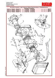
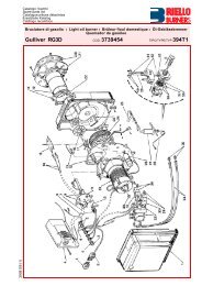
DESCRIZIONE BRUCIATORE (A)1 Elettro<strong>di</strong> <strong>di</strong> accensione2 Testa <strong>di</strong> combustione3 Vite per regolazione testa <strong>di</strong> combustione4 Vite per il fissaggio ventilatore alla flangia5 Pompa6 Martinetto idraulico per la regolazione dellaserranda aria nella posizione <strong>di</strong> 1° e 2° sta<strong>di</strong>o.Durante la sosta del bruciatore la serrandadell’aria è completamente chiusa perridurre al minimo le <strong>di</strong>spersioni termichedella caldaia dovute al tiraggio del caminoche richiama l’aria dalla bocca <strong>di</strong> aspirazionedel ventilatore7 Ingresso aria nel ventilatore8 Serrande aria9 Presa <strong>di</strong> pressione ventilatore10 Flangia per il fissaggio alla caldaia11 Disco <strong>di</strong> stabilit<strong>à</strong> fiamma12 Guide per apertura bruciatore ed ispezionealla testa <strong>di</strong> combustione13 Prolunghe per guide 12)14 Motore elettrico15 Trasformatore d’accensione16 Contattore motore e relè termico con pulsante<strong>di</strong> sblocco17 STATUS18 Morsettiera19 Due interruttori elettrici:- uno per “acceso - spento bruciatore”- uno per “1° - 2° sta<strong>di</strong>o”20 Passacavi per i collegamenti elettrici a curadell’installatore21 Apparecchiatura elettrica con avvisatoreluminoso <strong>di</strong> blocco e pulsante <strong>di</strong> sblocco22 Visore fiamma23 Fotoresistenza per il controllo presenzafiamma24 Valvola 2° sta<strong>di</strong>o25 Elettrovalvola <strong>di</strong> sicurezza26 Valvola 1° sta<strong>di</strong>o(A)mm A B C kgRL 190 1250 725 785 75(B)Vi sono due possibilit<strong>à</strong> <strong>di</strong> blocco del bruciatore:Blocco apparecchiatura: l’accensione del pulsantedell’apparecchiatura 21)(A) avverte che ilbruciatore è in blocco.Per sbloccare premere il pulsante (dopo almeno10 s dal blocco).Blocco motore: per sbloccare premere il pulsantedel relè termico 16)(A).IMBALLO - PESO (B) - misure in<strong>di</strong>cative• L’ imballo del bruciatore appoggia su unapedana in legno particolarmente adatta ai carrellielevatori. Le <strong>di</strong>mensioni <strong>di</strong> ingombrodell'imballo sono riportate nella tabella (B).• Il peso del bruciatore completo <strong>di</strong> imballo èin<strong>di</strong>cato nella tabella (B).INGOMBRO (C) - misure in<strong>di</strong>cativeL'ingombro del bruciatore è riportato in fig. (C).Tener presente che per ispezionare la testa <strong>di</strong>combustione il bruciatore deve essere apertoarretrandone la parte posteriore sulle guide.L'ingombro del bruciatore aperto è in<strong>di</strong>cato dallaquota I.mm A B C D E F G H IRL 190 756 366 390 555 696 370 222 430 1102(C)CORREDO2 - Tubi flessibili (L = 1350 mm)2 - Guarnizioni per tubi flessibili2 - Nipples per tubi flessibili1 - Schermo termico4 - Prolunghe 13)(A) per guide 12)(A)4 - Viti per fissare la flangia del bruciatore allacaldaia: M 16 x 402 - Ugelli1 - Istruzione1 - Catalogo ricambi8
BRENNERBESCHREIBUNG (A)1 Zündelektroden2 Flammkopf3 Einstellschraube Flammkopf4 Schraube für <strong>di</strong>e Befestigung des Gebläsesam Flansch5 Pumpe6 Hydraulikzylinder zur Einstellung der Luftklappeauf der 1. und 2. Stufe.Bei Brennerstillstand ist <strong>di</strong>e Luftklappegeschlossen, um <strong>di</strong>e Wärmeverluste desKessels durch den Kaminzug mit Luftnachführungvon der Saugöffnung des Gebläseszu vermeiden7 Lufteinlaß zum Gebläse8 Luftklappen9 Gebläsedruckanschluß10 Befestigungsflansch am Kessel11 Scheibe für Flammenstabilität12 Gleitschienen zum Ausschwenken des Brennersund für <strong>di</strong>e Kontrolle des Flammkopfs13 Verlängerungen zu Gleitschienen 12)14 Elektromotor15 Zündtransformator16 Motorschaltglied und Wärmerelais mitEntriegelungsschalter17 STATUS18 Klemmenbrett19 Zwei Schalter:- einer für “Brenner eingeschaltet-ausgeschaltet”- einer für “1. - 2. Stufe”20 Kabeldurchgänge für <strong>di</strong>e Elektroanschlüssevom Installateur auszuführen21 Steuergerät mit Kontrollampe für Störabschaltungund Entriegelungsschalter22 Sichtfenster23 Lichtelektrischer Widerstand für <strong>di</strong>e Flammenüberwachung24 Ventile 2. Stufe25 Sicherheits-Elektroventil26 Ventile 1. StufeDie Störabschaltungen des Brenners könnenzweierlei Art sein:Störabschaltung des Gerätes: Das Aufleuchtendes Druckknopfes des Gerätes 21)(A) weist aufeine Störabschaltung des Brenners hin.Zur Entriegelung den Druckknopf drücken,mindestens 10 s nach der Störabschaltung.Störabschaltung des Motors: Entriegelung durchDrükken auf den Druckknopf des Überstromauslösers16)(A).VERPACKUNG - GEWICHT (B) - Richtwerte• Der Brenner steht auf einem besondersfür<strong>di</strong>e Handhabung mit Hubwagen geeignetemHolzrahmen. Die Außenabmessungen der Verpackungsind in Tabelle (B) aufgeführt.• Das Gesamtgewicht des Brenners einschließlichVerpackung wird aus Tabelle (B)ersichtlich (B).ABMESSUNGEN (C) - RichtwerteDie Brennerabmessungen sind in der Abb. (C)angeführt.Zur Inspektion des Flammkopfes muß der Brennergeöffnet und der hintere Teil auf denGleitschienen zurückgeschoben werden.Die Abmessungen des offenen Brenners sindunter I aufgeführt.AUSSTATTUNG2 - Schläuche (L = 1350 mm)2 - Schlauch<strong>di</strong>chtungen2 - Schlauchnippel1 - Wärmeschild4 - Verlängerungen 13)(A) für Gleitschienen12)(A)4 - Schrauben für <strong>di</strong>e Befestigung des Brennerflanschsam Kessel: M 16 x 402 - Düsen1 - Anleitung1 - Ersatzteile KatalogBURNER DESCRIPTION (A)1 Ignition electrodes2 Combustion head3 Screw for combustion head adjustment4 Screw for fixing fan to flange5 Pump6 Hydraulic cylinder for regulation of the airgate valve in 1st and 2nd stage positions.When the burner is not operating the air gatevalve is fully closed in order to reduce to aminimum heat <strong>di</strong>spersion from the b<strong>oil</strong>er dueto the flue draught which draws air from thefan suction inlet.7 Air inlet to fan8 Air gate valves9 Fan pressure test point10 B<strong>oil</strong>er mounting flange11 Flame stability <strong>di</strong>sk12 Slide bars for opening the burner an<strong>di</strong>nspecting the combustion head13 Extensions for slide bars 12)14 Electrical motor15 Ignition transformer16 Motor contactor and thermal cut-out withreset button17 STATUS18 Terminal strip19 Two switches:- one “burner off - on”- one for “1st - 2nd stage operation”20 Fairleads for electrical connections byinstaller21 Control box with lock-out pilot light and lockoutreset button22 Flame inspection window23 Photocell for flame presence control24 2nd stage valve25 Safety solenoid valve26 1st stage valveTwo types of burner failure may occur:Control Box Lock-out: if the control box 21)(A)pushbutton lights up, it in<strong>di</strong>cates that the burneris in lock-out.To reset, press the pushbutton, no sooner than10 s after the lock-out.Motor trip: release by pressing the pushbuttonon thermal relay 16)(A).PACKAGING - WEIGHT (B) - Approximatemeasurements• The <strong>burners</strong> stands on a wooden base whichcan be lifted by fork-lifts. Outer <strong>di</strong>mensions ofpackaging are in<strong>di</strong>cated in (B).• The weight of the burner complete with packagingis in<strong>di</strong>cated in Table (B).MAX. DIMENSIONS (C) - Approximate measurementsThe maximum <strong>di</strong>mensions of the burner aregiven in (C).Bear in mind that inspection of the combustionhead requires the burner to be opened and therear part withdrawn on the slide bars.The maximum <strong>di</strong>mension of the burnerwhenopen, without casing, is give in measurement I.STANDARD EQUIPMENT2 - Flexible hoses (L = 1350 mm)2 - Gaskets for flexible hoses2 - Nipples for flexible hoses1 - Thermal insulation screen4 - Extensions 13)(A) for slide bars 12)(A)4 - Screws to secure the burner flange to theb<strong>oil</strong>er: M 16 x 402 - Nozzles1 - Instruction booklet1 - Spare parts listDESCRIPTION BRULEUR (A)1 Electrodes d'allumage2 Tête de combustion3 Vis pour réglage tête de combustion4 Vis de fixation du ventilateur <strong>à</strong> la bride5 Pompe6 Vérin hydraulique de réglage du volet d’airsur la position de 1ère ou 2ème allure. Lorsde l'arrêt du brûleur ce volet d'air est complètementfermé afin de réduire le plus possibleles <strong>di</strong>spersions thermiques de lachau<strong>di</strong>ère causées par le tirage du conduitde rappel d'air sur la bouche d'aspiration duventilateur7 Entrée air dans le ventilateur8 Volets d'air9 Prise de pression ventilateur10 Bride de fixation <strong>à</strong> la chau<strong>di</strong>ère11 Disque de stabilité de flamme12 Guides pour ouverture brûleur et inspectionde la tête de combustion13 Rallonges de guides 12)14 Moteur électrique15 Transformateur d’allumage16 Contacteur moteur et relais thermique avecbouton de déblocage17 STATUS18 Bornier19 Deux interrupteurs électriques:- un pour “allumé - éteint brûleur”- un pour “1ère - 2ème allure”20 Passe-câbles pour les connexions électriques<strong>à</strong> la charge de l’installateur21 Coffret de sécurité avec signal lumineux deblocage et bouton de déblocage22 Viseur flamme23 Photorésistance pour le contrôle présenceflamme24 Electrovanne de 2ème allure25 Electrovanne de sécurité26 Electrovanne de 1ère allureIl existe deux types de blocage du brûleur:Blocage coffret: l'allumage du bouton du coffretde sécurité 21)(A) avertit que le brûleur s'estbloqué.Pour le débloquer appuyer sur le bouton, aumoins 10 s après le blocage.Blocage moteur: pour le débloquer appuyer surle bouton-poussoir du relais thermique 16)(A).EMBALLAGE - POIDS (B) - Mesures in<strong>di</strong>catives• Le brûleur est placé sur une palette qui peutêtre soulevée par des chariots transpalettes.Les <strong>di</strong>mensions d’encombrement de l’emballagesont reportées dans le tableau (B).• Le poids du brûleur avec son emballage estin<strong>di</strong>qué dans le tab. (B).ENCOMBREMENT (C) - Mesures in<strong>di</strong>cativesL'encombrement du brûleur est in<strong>di</strong>qué dans letab. (C).Il faut tenir compte du fait que pour inspecter latête de combustion, le brûleur doit être ouvert, lapartie arrière reculée sur les guides. L'encombrementdu brûleur ouvert, sans carter, estin<strong>di</strong>qué par la cote I.EQUIPEMENT STANDARD2 - Tuyaux flexibles (L = 1350 mm)2 - Joints pour tuyaux flexibles2 - Nipples pour tuyaux flexibles1 - Ecran thermique4 - Rallonges 13)(A) de guides 12)(A)4 - Vis pour fixer la bride du brûleur <strong>à</strong> lachau<strong>di</strong>ère: M 16 x 402 - Gicleurs1 - Instructions1 - Catalogue pièces détachées9
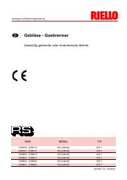
CAMPO DI LAVORO (A)Il bruciatore RL 190 può funzionare in due mo<strong>di</strong>:monosta<strong>di</strong>o e bista<strong>di</strong>o.m mbar(A)(B)mm A B CRL 190 230 325-368 M 16(C)La PORTATA del 1° sta<strong>di</strong>o va scelta entrol'area A del <strong>di</strong>agramma a lato.La PORTATA del 2° sta<strong>di</strong>o va scelta entrol'area B. Quest' area fornisce la portata massimadel bruciatore in funzione della pressionein camera <strong>di</strong> combustione.Attenzione:il CAMPO DI LAVORO è stato ricavato alla temperaturaambiente <strong>di</strong> 20 °C, alla pressione barometrica<strong>di</strong> 1000 mbar (circa 100 m s.l.m.) e conla testa <strong>di</strong> combustione regolata come in<strong>di</strong>cato ap. 12.CALDAIA DI PROVA (B)Il campo <strong>di</strong> lavoro è stato ricavato in specialicaldaie <strong>di</strong> prova secondo meto<strong>di</strong>che fissatedalle norme EN 267.Riportiamo in (B) <strong>di</strong>ametro e lunghezza dellacamera <strong>di</strong> combustione <strong>di</strong> prova.Esempio: Portata 65 kg/h:<strong>di</strong>ametro 60 cm - lunghezza 2 m.Qualora il bruciatore dovesse bruciare in unacamera <strong>di</strong> combustione commerciale nettamentepiù piccola, è opportuna una prova preliminare.INSTALLAZIONEPIASTRA CALDAIA (C)Forare la piastra <strong>di</strong> chiusura della camera <strong>di</strong>combustione come in (C). La posizione dei forifilettati può essere tracciata utilizzando lo schermotermico a corredo del bruciatore.LUNGHEZZA BOCCAGLIO (D)La lunghezza del boccaglio va scelta secondo lein<strong>di</strong>cazioni del costruttore della caldaia e, in ognicaso, deve essere maggiore dello spessoredella porta della caldaia, completa <strong>di</strong> refrattario.La lunghezza, L (mm), <strong>di</strong>sponibile è <strong>di</strong> 370 mm.Per le caldaie con giro dei fumi anteriore 12), ocon camera ad inversione <strong>di</strong> fiamma, eseguireuna protezione in materiale refrattario 10), trarefrattario caldaia 11) e boccaglio 9).La protezione deve consentire al boccaglio <strong>di</strong>essere estratto.Per le caldaie con il frontale raffreddato adacqua non è necessario il rivestimento refrattario10)-11)(D), se non vi è espressa richiesta delcostruttore della caldaia.FISSAGGIO DEL BRUCIATORE ALLACALDAIA (D)Smontare il boccaglio 9) dal bruciatore 6).- Allentare le 4 viti 3) e togliere il cofano 1).- Togliere le viti 2) dalle due guide 5).- Togliere le due viti 4) che fissano il bruciatore6) alla flangia 7).- Sfilare il boccaglio 9) completo <strong>di</strong> flangia 7) eguide 5).Fissare la flangia 7)(D) alla piastra della caldaiainterponendo la guarnizione 8)(D) data acorredo. Utilizzare le 4 viti pure date a corredodopo averne protetto la filettatura con prodottiantigrippanti.La tenuta bruciatore-caldaia deve essere ermetica.(D)10
REGELBEREICH (A)Der Brenner RL 190 kann auf zwei Arten funktionieren:ein- und zweistufig.Der DURCHSATZ der 1. Stufe wird innerhalbdes Felds A aus den nebenstehenden Kurvenausgewählt.Der DURCHSATZ der 2. Stufe wird innerhalbdes Felds B ausgewählt. Dieses Feld zeigt denHöchstdurchsatz des Brenners in Abhängigkeitdes Brennkammerdrucks.Achtung:der REGELBEREICH wurde bei einerRaumtemperatur von 20 °C, einem barometrischenDruck von 1000 mbar (ungefähr 100 mü.d.M.) und einem wie auf Seite 13 eingestelltenFlammkopf gemessen.PRÜFKESSEL (B)Die Regelbereiche wurden an speziellenPrüfkesseln gemäß EN 267 gemessen.In (B) sind Durchmesser und Länge des Prüf-Verbrennungsraums angegeben.Beispiel: Durchsatz 65 kg/h:Durchmesser = 60 cm, Länge = 2 m.Falls der Brenner in einer handelsüblich wesentlichkleineren Brennkammer brennt, mußzunächst eine Probe durchgeführt werden.INSTALLATIONKESSELPLATTE (C)Die Abdeckplatte der Brennkammer wie in (C)gezeigt vorbohren. Die Position der Gewindebohrungenkann mit der zur Grundausstattunggehörenden Isolierplatte ermittelt werden.FLAMMROHRLÄNGE (C)Die Länge des Flammrohrs wird entsprechendder Angaben des Kesselherstellers gewählt undmuß in jedem Fall länger sein als <strong>di</strong>e Stärke derKesseltür, einschließlich des Schamottesteins.Die verfügbare Länge, L (mm), ist 370 mm.Für Heizkessel mit vorderem Rauchumlauf 12)oder mit Kammer mit Flammeninversion mußeine Schutzschicht aus feuerfestem Material10), zwischen Schamottestein 11) und Flammrohr9) eingeplant werden.Diese Schutzschicht muß so angelegt sein, daßdas Flammrohr ausbaubar ist.Für <strong>di</strong>e Kessel mit wassergekühlter Frontseiteist <strong>di</strong>e Verkleidung mit feuerfestem Material 10)-11)(D) nicht notwen<strong>di</strong>g, sofern nicht ausdrücklichvom Kesselhersteller erfordert.BEFESTIGUNG DES BRENNERS AM HEIZ-KESSEL (D)Das Flammrohr 9) vom Brenner 6) ausbauen.- Die 4 Schrauben 3) lockern und <strong>di</strong>e Verkleidung1) abnehmen.- Die Schrauben 2) von den beiden Führungen5) entfernen.- Die beiden Befestigungsschrauben 4) desBrenners 6) mit dem Flansch 7) abnehmen.- Das Flammrohr 9) mit Flansch 7) und Führungen5) herausziehen.Den Flansch 7)(D) durch Zwischenlegen derbeigepackten Dichtung 8)(D) an <strong>di</strong>e Kesselplattebefestigen. Die ebenfalls mitgelieferten 4Schrauben verwenden, deren Gewinde miteinem Antifressmittel geschützt werden. DieDichtung zwischen Brenner und Heizkesselmuß <strong>di</strong>cht sein.FIRING RATE (A)The RL 190 Model <strong>burners</strong> can work in twoways: one-stage and two-stage.1st stage DELIVERY must be selected withinarea A of the adjacent <strong>di</strong>agram.2nd stage DELIVERY must be selected withinarea B. This area provides the maximum deliveryof the burner in relation to the pressure inthe combustion chamber.Important:The FIRING RATE area values have beenobtained considering a surroun<strong>di</strong>ng temperatureof 20°C, and an atmospheric pressure of 1000mbar (approx. 100 m above sea level) and withthe combustion head adjusted as shown onpage 13.TEST BOILER (B)The firing rates were set in relation to specialtest b<strong>oil</strong>ers in accordance with the methodsdefined in EN 267 standards.Figure (B) in<strong>di</strong>cates the <strong>di</strong>ameter and length ofthe test combustion chamber.Example: delivery 65 kg/hour:<strong>di</strong>ameter = 60 cm; length = 2 m.Whenever the burner is operated in a muchsmaller commercially-available combustionchamber, a preliminary test should be performed.INSTALLATIONBOILER PLATE (C)Drill the combustion chamber locking plate asshown in (C). The position of the threaded holescan be marked using the thermal screen suppliedwith the burner.BLAST TUBE LENGTH (C)The length of the blast tube must be selectedaccor<strong>di</strong>ng to the in<strong>di</strong>cations provided by themanufacturer of the b<strong>oil</strong>er, and in any case itmust be greater than the thickness of the b<strong>oil</strong>erdoor complete with its fettling. The length available,L (mm), is 370 mm.For b<strong>oil</strong>ers with front flue passes 12) or flameinversion chambers, protective fettling in refractorymaterial 10) must be inserted between theb<strong>oil</strong>er fettling 11) and the blast tube 9).This protective fettling must not compromise theextraction of the blast tube.For b<strong>oil</strong>ers having a water-cooled front therefractory fettling 10)-11)(D) is not requiredunless it is expressly requested by the b<strong>oil</strong>ermanufacturer.SECURING THE BURNER TO THE BOILER(D)Disassemble the blast tube 9) from the burner 6)by procee<strong>di</strong>ng as follows:- Loosen the four screws 3) and remove thecover 1).- Remove the screws 2) from the two slide bars5).- Remove the two screws 4) fixing the burner 6)to the flange 7).- Withdraw the blast tube 9) complete withflange 7) and slide bars 5).Secure flange 7)(D) to the b<strong>oil</strong>er plate interposingthe supplied gasket 8)(D). Use the 4 screwsprovided after having protected the thread withantiscruffing products.The burner-b<strong>oil</strong>er seal must be airtight.PLAGE DE PUISSANCE (A)Le brûleur RL 190 peut fonctionner en deuxmodes: <strong>à</strong> une allure et <strong>à</strong> deux allures.Le DEBIT de 1ère allure doit être choisi dans laplage A du <strong>di</strong>agramme ci-contre.Le DEBIT de 2ème allure doit être choisi dansla plage B. Cette plage in<strong>di</strong>que le débit maximumdu brûleur en fonction de la pression dansla chambre de combustion.Attention:La PLAGE DE PUISSANCE a été calculée <strong>à</strong>une température ambiante de 20 °C, <strong>à</strong> unepression barométrique de 1000 mbars (environ100 m au-dessus du niveau de la mer) et avecla tête de combustion réglée comme in<strong>di</strong>que lap. 13.CHAUDIERE D'ESSAI (B)Les plages de puissance ont été établies surdes chau<strong>di</strong>ères d'essai spéciales selon desméthodes fixées par les normes EN 267.Nous reportons fig. (B) le <strong>di</strong>amètre et lalongueur de la chambre de combustion d'essai.Exemple: Débit 65 kg/h:<strong>di</strong>amètre 60 cm - longueur 2 m.Si le brûleur devait fonctionner sur une chambrede combustion commerciale nettement pluspetite, il serait opportun d'effectuer un essaipréliminaire.INSTALLATIONPLAQUE CHAUDIERE (C)Percer la plaque de fermeture de la chambre decombustion comme sur la fig. (C). La positiondes trous filetés peut être tracée en utilisantl'écran thermique du brûleur.LONGUEUR BUSE (C)Choisir la longueur de la buse selon les in<strong>di</strong>cationsdu constructeur de la chau<strong>di</strong>ère, elle doit,en tous cas, être supérieure <strong>à</strong> l'épaisseur de laporte de la chau<strong>di</strong>ère, matériau réfractaire compris.La longueur L (mm) <strong>di</strong>sponible est 370 mm.Pour les chau<strong>di</strong>ères avec circulation desfumées sur l'avant 12), ou avec chambre <strong>à</strong>inversion de flamme, réaliser une protection enmatériau réfractaire 10), entre réfractairechau<strong>di</strong>ère 11) et buse 9).La protection doit permettre l'extraction de labuse.Pour les chau<strong>di</strong>ères dont la partie frontale estrefroi<strong>di</strong>e par eau, le revêtement réfractaire 10)-11)(D) n'est pas nécessaire, sauf in<strong>di</strong>cationexpresse du constructeur de la chau<strong>di</strong>ère.FIXATION DU BRULEUR A LA CHAUDIERE(D)Démonter la buse 9) du brûleur 6).- Desserrer les 4 vis 3) et retirer le coffret 1).- Retirer les vis 2) des deux guides 5).- Retirer les 2 vis 4) qui fixent le brûleur 6) <strong>à</strong> labride 7).- Enlever la buse 9) avec bride 7) et guides 5).Fixer la bride 7)(D) <strong>à</strong> la plaque de la chau<strong>di</strong>èreen installant le joint 8)(D) fourni de série. Utiliserles 4 vis fournies après en avoir protégé le filetageavec des produits antigrippants.L'étanchéité brûleur-chau<strong>di</strong>ère doit être parfaite.11
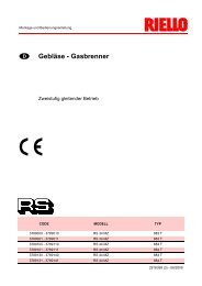
10,010,511,012,012,313,013,814,015,015,316,017,017,518,019,019,520,021,522,022,523,023,524,024,525,025,526,026,527,027,528,0(A)(D)(E)GPHkg/h10 bar 12 bar 14 bar38,4 42,4 46,140,4 44,6 48,442,3 46,7 50,746,1 50,9 55,347,3 52,2 56,750,0 55,1 59,953,1 58,5 63,353,8 59,4 64,557,7 63,6 69,258,8 64,9 70,561,5 67,9 73,865,4 72,1 78,467,3 74,2 80,769,2 76,4 83,073,0 80,6 87,675,0 82,7 89,976,9 84,8 92,282,7 91,2 99,184,6 93,3 101,486,5 95,5 103,788,4 97,6 106,090,4 99,7 108,392,2 101,8 110,694,2 104,0 112,996,1 106,0 115,398,0 108,2 117,699,9 110,3 119,9101,9 112,4 122,2103,8 114,5 124,5105,7 116,7 126,8107,6 118,8 129,1kW12 bar502,9529,0553,9603,7619,1653,5693,8704,5754,3769,7805,3855,1880,0906,1956,0980,91005,81081,71106,61132,61157,51182,41207,31233,51257,21283,21308,21333,11358,01384,11409,0REGOLAZIONE TESTA DI COMBUSTIONEFLAMMKOPFEINSTELLUNGSETTING THE COMBUSTION HEADREGLAGE TETE DE COMBUSTION(F)(G)N° Tacche - Kerben - Notches - Encoches(B)(C)Portata <strong>gasolio</strong> in 2° sta<strong>di</strong>o Heizöldurchsatz in 2. Stufe kg/h<strong>Light</strong> <strong>oil</strong> delivery in 2nd stage Débit <strong>fioul</strong> <strong>à</strong> la 2ème allure12SCELTA DEGLI UGELLI PER IL 1° E 2° STA-DIOEntrambi gli ugelli vanno scelti tra quelli in<strong>di</strong>catinella tabella (A).Il primo ugello determina la portata del bruciatorein 1° sta<strong>di</strong>o.Il secondo ugello funziona assieme al primo edentrambi determinano la portata del bruciatorein 2° sta<strong>di</strong>o.Le portate del 1° e del 2° sta<strong>di</strong>o devono esserecomprese tra i valori in<strong>di</strong>cati a pag. 4.Utilizzare ugelli con angolo <strong>di</strong> polverizzazione60° alla pressione consigliata <strong>di</strong> 12 bar.Generalmente i due ugelli sono <strong>di</strong> eguale portatama l'ugello del 1° sta<strong>di</strong>o può avere una portatainferiore al 50 % della portata totale,quando si desidera ridurre il picco <strong>di</strong> contropressioneal momento dell'accensione (il bruciatoreconsente buoni valori <strong>di</strong> combustione anche conrapporti 40 - 100% tra 1° e 2° sta<strong>di</strong>o).EsempioPotenza caldaia = 1630 kW - ren<strong>di</strong>mento 90 %Potenza richiesta al bruciatore =1630 : 0,9 = 1812 kW;1812 : 2 = 906 kW per ugellooccorrono 2 ugelli uguali, 60°, 12 bar:1° = 18 GPH - 2° = 18 GPH,oppure due ugelli <strong>di</strong>fferenti:1° = 16 GPH - 2° = 20 GPH.NOTA. I due ugelli dati a corredo possonoessere utilizzati quando corrispondono alla portatarichiesta. In caso contrario vanno sostituiticon altri due <strong>di</strong> portata adatta all'impianto.MONTAGGIO DEGLI UGELLIA questo punto dell'installazione il bruciatore èancora separato dal boccaglio; è perciò possibilemontare l'ugello con la chiave a tubo 1)(B)(da 16 mm), dopo aver tolto i tappi in plastica2)(B), passando dall'apertura centrale del <strong>di</strong>sco<strong>di</strong> stabilit<strong>à</strong> fiamma. Non usare prodotti per latenuta: guarnizioni, nastro o sigillanti. Fareattenzione <strong>di</strong> non ammaccare o incidere la sede<strong>di</strong> tenuta dell'ugello. Il serraggio dell'ugello deveessere energico ma senza raggiungere lo sforzomassimo consentito dalla chiave.L'ugello per il 1° sta<strong>di</strong>o <strong>di</strong> funzionamento èquello sottostante gli elettro<strong>di</strong> d'accensione, fig.(C).Controllare che gli elettro<strong>di</strong> siano posizionaticome in fig. (C).Rimontare, infine, il bruciatore 3)(D) sulle guide2) e farlo scorrere fino alla flangia 5), tenendololeggermente sollevato per evitare che il <strong>di</strong>sco <strong>di</strong>stabilit<strong>à</strong> fiamma entri in contrasto con il boccaglio.Avvitare le viti 1) sulle guide 2) e le viti 4) che fissan<strong>oil</strong> bruciatore alla flangia.Qualora fosse necessario sostituire l'ugello conbruciatore gi<strong>à</strong> applicato alla caldaia, procederecome segue:- Aprire il bruciatore sulle guide come in fig.(D)p.10.- Togliere i da<strong>di</strong> 1)(E) ed il <strong>di</strong>sco 2)- Sostituire l'ugello con la chiave 3)(E).REGOLAZIONE TESTA DI COMBUSTIONELa regolazione della testa <strong>di</strong> combustione<strong>di</strong>pende unicamente dalla portata del bruciatorein 2° sta<strong>di</strong>o, cioè dalla portata dei due ugelliscelti nella tabella (A).Ruotare la vite 4)(F) fino a far collimare la taccain<strong>di</strong>cata dal <strong>di</strong>agramma (G) con il piano anterioredella flangia 5)(F).Esempio:RL 190 con due ugelli da 18 GPH e pressione inpompa 12 bar.Trovare nella tabella (A) la portata dei due ugellida 18 GPH.76,4 + 76,4 = 152,8 kg/h.Il <strong>di</strong>agramma (G) in<strong>di</strong>ca che per una portata <strong>di</strong>152,8 kg/h il bruciatore RL 190 necessita <strong>di</strong> unaregolazione della testa <strong>di</strong> combustione a 4 tacchecirca, come illustrato in fig. (F).
WAHL DER DÜSE FÜR DIE 1. UND 2. STUFEBeide Düsen werden unter den in der Tabelle(A) angegebenen Typen ausgewählt.Die erste Düse bestimmt den Durchsatz desBrenners in der 1. Stufe.Die zweite Düse funktioniert zusammen mit derersten und beide bestimmen den Durchsatz desBrenners in der 2. Stufe.Der Durchsatz der 1. und 2. Stufe müssen unterden auf Seite 5 angegebenen Werten ausgewähltwerden.Düsen mit einem Zerstäubungswinkel von 60° beimempfohlenen Druck von 12 bar verwenden.Die beiden Düsen haben im allgemeinen gleicheDurchsätze, <strong>di</strong>e Düse der 1. Stufe kann jedocheinen Durchsatz von weniger als 50% desGesamtdurchsatzes haben, wenn der Spitzenwertdes Gegendrucks im Augenblick desZündens vermindert werden soll (der Brennergestattet gute Verbrennungswerte auch mit 40 -100 % - Verhältnis zwischen 1. und 2. Stufe).BeispielKesselleistung = 1630 kW - Wirkungsgrad 90 %Geforderte Brennerleistung =1630 : 0,9 = 1812 kW;1812 : 2 = 906 kW pro Düseerfordert werden 2 gleiche Düsen, 60°, 12 bar:1° = 18 GPH - 2° = 18 GPH,oder zwei unterschiedliche Düsen:1° = 16 GPH - 2° = 20 GPH.VERMERKE. Die zwei beigestellten Düsen könnenbenutz werden, wenn sie mit dem verlangtenDurchsatz übereinstimmen. Imgegenteiligen Fall müssen sie mit zwei anderenersetzt werden, deren Durchsatz für <strong>di</strong>e Anlagegeeignet ist.DÜSENMONTAGEWährend <strong>di</strong>eser Einbauphase ist der Brennernoch vom Flammrohr getrennt; es kann also <strong>di</strong>eDüse mit dem Steckschlüssel 1)(B) (16 mm)montiert werden, und zwar nach Abnahme derKunststoffschrauben 2)(B) und über <strong>di</strong>e mittigeÖffnung der Scheibe für <strong>di</strong>e Stabilisierung derFlamme. Keine Dichtzusätze verwenden: Dichtungen,Band oder Dichtmasse. Achten Siedarauf, daß dabei der Sitz der Düsen<strong>di</strong>chtungnicht beschä<strong>di</strong>gt wird. Die Düse muß fest angezogenwerden, jedoch ohne <strong>di</strong>e maximale Kraftdes Schlüssels zu erreichen.Die Düse für <strong>di</strong>e 1. Stufe ist <strong>di</strong>e Düse neben denZündelektroden, Abb. (C).Kontrollieren Sie, ob <strong>di</strong>e Elektroden wie in Abb.(C) ausgerichtet sind.Anschließend den Brenner 3)(D) auf <strong>di</strong>e Führungen2) montieren und bis zum Flansch 5) schieben, ihndabei leicht angehoben halten, um Behinderungenzwischen der Scheibe für <strong>di</strong>e Flammenstabilität unddem Flammrohr zu vermeiden.Die Schrauben 1) auf <strong>di</strong>e Führungen 2) und <strong>di</strong>eBefestigungsschrauben 4) des Brenners mitdem Flansch andrehen.Für einen eventuellen Düsenaustausch beiangebrachtem Brenner am Kessel ist wie folgtzu verfahren:- Den Brenner im Bereich der Führungen öffnen,vgl. Abb. (D)S.10.- Die Muttern 1)(E) und <strong>di</strong>e Scheibe 2) abnehmen- Die Düse mit dem Schlüssel 3)(E) austauschen.EINSTELLUNG DES FLAMMKOPFSDie Einstellung des Flammkopfs hängt einzigvom Durchsatz des Brenners in der 2. Stufe ab,bzw. vom Durchsatz der beiden in der Tabelle(A) ausgewählten Düsen.Die Schraube 4)(F) soweit verdrehen, bis <strong>di</strong>eKerbe in Diagramm (G) mit der vorderen Flächevon Flansch 5)(F) zusammenfällt.Beispiel:RL 190 mit zwei Düsen zu 18 GPH undPumpendruck 12 bar.Suchen Sie in der Tabelle (A) den Durchsatz derbeiden Düsen zu 18 GPH:76,4 + 76,4 = 152,8 kg/h.Das Diagramm (G) zeigt, daß für einen Durchsatzvon 152,8 kg/h für den Brenner RL 190eine Regulierung des Flammkopfes um ungefähr4 Kerben benötigt wird, wie in der Abb. (F)dargestellt.CHOICE OF NOZZLES FOR 1ST AND 2NDSTAGEBoth nozzles must be chosen from among thoselisted in Table (A).The first nozzle determines the delivery of theburner in the 1st stage.The second nozzle works together with the 1stnozzle to determine the delivery of the burner inthe 2nd stage.The deliveries of the 1st and 2nd stages mustbe contained within the value range in<strong>di</strong>cated onpage 6.Use nozzles with a 60° spray angle at the recommendedpressure of 12 bar.As a rule the two nozzles have equal deliveriesbut the 1st stage nozzle may have a deliveryless than 50% of the total delivery when areduction of the counter-pressure peak isdesired at the moment of starting (the burnerallows good combustion rates also with a 40 -100 % ratio between the 1st and 2nd stage).ExampleB<strong>oil</strong>er output = 1630 kW - efficiency 90 %Output required by the burner =1630 : 0,9 =1812 kW;1812 : 2 =906 KW per nozzle;therefore, two equal, 60°, 12 bar nozzles arerequired:1° = 18 GPH - 2° = 18 GPH,or the following two <strong>di</strong>fferent nozzles:1° = 16 GPH - 2° = 20 GPH.NOTE. The two supplied nozzles may be usedwhen they correspond to the required delivery,otherwise they are to be replaced by others witha delivery suitable to the system.NOZZLE ASSEMBLYAt this stage of installation the burner is still <strong>di</strong>sassembledfrom the blast tube; it is thereforepossible to fit the nozzle with the box spanner1)(B) (16 mm), after having removed the plasticplugs 2)(B), fitting the spanner through the centralhole in the flame stability <strong>di</strong>sk. Do not useany sealing products such as gaskets, sealingcompound, or tape. Be careful to avoid damagingthe nozzle sealing seat. The nozzles mustbe screwed into place tightly but not to the maximumtorque value provided by the wrench.The nozzle for the 1st stage of operation is theone lying beneath the firing electrodes Fig. (C).Make sure that the electrodes are positioned asshown in Figure (C).Finally remount the burner 3)(D) on the slidebars 2) and slide it up to the flange 5), keeping itslightly raised to prevent the flame stability <strong>di</strong>skfrom pressing against the blast tube.Tighten the screws 1) on the slide bars 2) andscrews 4) fixing the burner to the flange.If it proves necessary to change a nozzle withthe burner already fitted to the b<strong>oil</strong>er, proceedas outlined below:- Pull back the burner on its slide bars as shownin fig. (D)p.10.- Remove the nuts 1)(E) and the <strong>di</strong>sk 2)- Use spanner 3)(E) to change the nozzles.COMBUSTION HEAD SETTINGThe setting of the combustion head dependsexclusively on the burner delivery in the 2ndstage - in other words, the combined delivery ofthe two nozzles selected in table (A).Turn screw 4)(F) until the notch shown in <strong>di</strong>agram(G) is level with the front surface of flange5)(F).Example:The RL 190 Model with two 18 GPH nozzlesand 12 bar pump pressure.Find the delivery of the two 18 GPH nozzles inTable (A):76,4 + 76,4 = 152,8 kg/h.Diagram (G) in<strong>di</strong>cates that for a delivery of152,8 kg/h the RL 190 Model requires the combustionhead to be set to approx. four notches,as shown in Figure (F).13CHOIX DES GICLEURS POUR LA 1ère ET LA2ème ALLURELes deux gicleurs doivent être choisis parmiceux in<strong>di</strong>qués dans le tableau (A).Le premier gicleur détermine le débit du brûleur<strong>à</strong> la 1ère allure.Le deuxième gicleur fonctionne en même tempsque le premier et tous les deux déterminent ledébit du brûleur <strong>à</strong> la 2ème allure.Les débits de la 1ère et de la 2ème allure doivent êtrecompris dans les limites in<strong>di</strong>quées <strong>à</strong> la page. 7.Utiliser des gicleurs <strong>à</strong> angle de pulvérisation de60° <strong>à</strong> la pression conseillée de 12 bar.Généralement, les deux gicleurs ont le mêmedébit mais, en cas de besoin, le gicleur de la1ère allure peut avoir un débit inférieur <strong>à</strong> 50 %du débit total, quand on veut réduire la pointe decontre-pression au moment de l'allumage (lebrûleur permet d’avoir de bonnes valeurs decombustion même avec un rapport 40 - 100 %entre la 1ère et la 2ème allure).ExemplePuissance chau<strong>di</strong>ère = 1630 kWrendement 90 %Puissance requise au brûleur =1630 : 0,9 = 1812 kW;1812 : 2 = 906 kW par gicleurIl faut 2 gicleurs identiques, 60°, 12 bar:1ère = 18 GPH - 2eme = 18 GPH,ou bien deux gicleurs <strong>di</strong>fférents:1ère = 16 GPH - 2ème = 20 GPH.NOTE. Les deux gicleurs fournis de série peuventêtre utilisés quand ils correspondent audébit voulu. Si ce n’est pas le cas, les changercontre deux autres gicleurs ayant un débitapproprié <strong>à</strong> l’installation.MONTAGE DU GICLEURA ce stade de l'installation, le brûleur est encoreséparé de la buse, par conséquent, on peutmonter le gicleur avec la clé <strong>à</strong> tubes 1)(B) (de16 mm), après avoir retiré les bouchons en plastique2)(B), en passant par l'ouverture centraledu <strong>di</strong>sque de stabilité de flamme. Ne pas utiliserde produits d'étanchéité: joints, ruban ou silicone.Faire attention <strong>à</strong> ne pas abîmer ou rayerle logement d'étanchéité du gicleur. Le serragedu gicleur doit être énergique mais sans atteindrel'effort maximum possible avec la clé.Le gicleur pour la 1ère allure de fonctionnementest celui qui se trouve sous les électrodesd'allumage, fig. (C).Contrôler que les électrodes soient positionnéescomme sur la fig. (C).Remonter le brûleur 3)(D) sur les guides 2) et fairecoulisser celui-ci jusqu'<strong>à</strong> la bride 5), en le tenantlégèrement soulevé pour éviter que le <strong>di</strong>sque destabilité de flamme ne bute contre la buse.Visser les vis 1) sur les guides 2) et le vis 4) quifixent le brûleur <strong>à</strong> la bride.S'il était nécessaire de remplacer un gicleur unefois que le brûleur a déj<strong>à</strong> été installé sur lachau<strong>di</strong>ère, procéder comme suit:- Ouvrir le brûleur sur les guides comme in<strong>di</strong>quéfig. (D)p.10.- Retirer les écrous 1)(E) et le <strong>di</strong>sque 2).- Remplacer les gicleurs avec la clé 3)(E).REGLAGE TETE DE COMBUSTIONLe réglage de la tête de combustion dépenduniquement du débit du brûleur <strong>à</strong> la 2èmeallure, c’est-<strong>à</strong>-<strong>di</strong>re du débit des deux gicleurschoisis dans le tableau (A).Tourner la vis 4)(F) jusqu'<strong>à</strong> faire coïncider lerepère in<strong>di</strong>qué sur le <strong>di</strong>agramme (G) avec leplan antérieur de la bride 5)(F).Exemple:RL 190 avec deux gicleurs de 18 GPH et pressionde la pompe 12 bar.Trouver dans le table (A) le débit des deuxgicleurs de 18 GPH:76,4 + 76,4 = 152,8 kg/h.Le <strong>di</strong>agramme (G) in<strong>di</strong>que que pour un débit de152,8 kg/h le brûleur RL 190 nécessite unréglage de la tête de combustion <strong>à</strong> 4 encochesenviron, comme l'illustre la fig. (F).
(A)(B)+ H- HL (m)Ø (mm)(m)12 14 16+ 4,0 71 138 150+ 3,0 62 122 150+ 2,0 53 106 150+ 1,0 44 90 150+ 0,5 40 82 1500 36 74 137- 0,5 32 66 123- 1,0 28 58 109- 2,0 19 42 81- 3,0 10 26 53- 4,0 - 10 25IMPIANTO IDRAULICO• ALIMENTAZIONE COMBUSTIBILECircuito bitubo (A)Il bruciatore è dotato <strong>di</strong> pompa autoaspirante eperciò, entro i limiti in<strong>di</strong>cati nella tabella, è ingrado <strong>di</strong> alimentarsi da solo.Cisterna più in alto del bruciatore AE' opportuno che la quota P non superi i 10 mper non sollecitare eccessivamente l'organo <strong>di</strong>tenuta della pompa e la quota V non superi i 4 mper rendere possibile l'autoinnesco della pompaanche con serbatoio quasi vuoto.Cisterna più in basso BNon si deve superare la depressione in pompa<strong>di</strong> 0,45 bar (35 cm Hg). Con una depressionemaggiore si ha liberazione <strong>di</strong> gas dal combustibile;la pompa <strong>di</strong>venta rumorosa e la sua durata<strong>di</strong>minuisce.Si consiglia <strong>di</strong> far arrivare la tubazione <strong>di</strong> ritornoalla stessa altezza della tubazione <strong>di</strong> aspirazione;è più <strong>di</strong>fficile il <strong>di</strong>sinnesco della tubazioneaspirante.Circuito ad anelloIl circuito ad anello è costituito da un condottoche parte dalla cisterna e ritorna in essa nelquale una pompa ausiliaria fa scorrere il combustibilesotto pressione. Una derivazionedall'anello alimenta il bruciatore. Questo circuitoè necessario quando la pompa del bruciatorenon riesce ad autoalimentarsi perchè la <strong>di</strong>stanzae/o il <strong>di</strong>slivello della cisterna sono superiori aivalori riportati in tabella.LegendaH = Dislivello pompa-valvola <strong>di</strong> fondoL = Lunghezza tubazioneØ = Diametro interno tubo1 = Bruciatore2 = Pompa3 = Filtro4 = Valvola manuale intercettazione5 = Condotto <strong>di</strong> aspirazione6 = Valvola <strong>di</strong> fondo7 = Valvola manuale a chiusura rapida concomando a <strong>di</strong>stanza (solo Italia)8 = Elettrovalvola <strong>di</strong> intercettazione (solo Italia)9 = Condotto <strong>di</strong> ritorno10 = Valvola <strong>di</strong> ritegno (solo Italia)• COLLEGAMENTI IDRAULICI (B)Le pompe hanno un by-pass che mette in comunicazioneil ritorno con l'aspirazione. Sonoinstallate sul bruciatore con il by-pass chiusodalla vite 6)(B)p.20.E' quin<strong>di</strong> necessario collegare entrambi i tubiflessibili alla pompa.Se la pompa viene fatta funzionare con il ritornochiuso e la vite <strong>di</strong> by-pass inserita, si guastaimme<strong>di</strong>atamente.Togliere i tappi dai raccor<strong>di</strong> <strong>di</strong> aspirazione eritorno della pompa.Avvitare al loro posto i tubi flessibili con leguarnizioni date a corredo.Nel montaggio i tubi flessibili non devono esseresollecitati a torsione.Disporre i tubi in modo che non possano esserecalpestati o venire a contatto con parti caldedella caldaia.Collegare, infine, l'altra estremit<strong>à</strong> dei tubi flessibiliai condotti <strong>di</strong> aspirazione e ritorno me<strong>di</strong>ante inipples dati a corredo.14
HYDRAULIKANLAGE• BRENNSTOFFZUFÜHRUNGZweistrangsystem (A)Der Brenner verfügt über eine selbstansaugendePumpe und kann sich daher, innerhalbder Grenzen der seitlich abgebildeten Tabelle,selbst versorgen.Tank höher als der Brenner ADie Strecke P sollte nicht höher als 10 m sein,damit das Dichtungsorgan der Pumpe nichtüberlastet wird, und <strong>di</strong>e Strecke V sollte 4 mnicht überschreiten, damit <strong>di</strong>e Selbsteinschaltungder Pumpe auch bei fast leerem Tankmöglich ist.Tank niedriger BDer Pumpenunterdruck von 0,45 bar (35 cmHg) darf nicht überschritten werden. Beihöheren Unterdruckwerten werden Gase desBrennstoffs befreit; <strong>di</strong>e Pumpe entwickelt mehrGeräusche und ihre Haltbarkeit wird beeinträchtigt.Es empfiehlt sich, <strong>di</strong>e Rücklaufleitung aufderselben Höhe wie <strong>di</strong>e Ansaugleitung ankommenzu lassen; das Abkuppeln der Ansaugleitungist schwieriger.KreisschaltungSie besteht aus einer Leitung, <strong>di</strong>e von und zumTank führt, in der eine Hilfspumpe den Brennstoffunter Druck fließen läßt. Eine Abzweigungdes Kreises speist den Brenner. DieseSchaltung ist nützlich, wenn <strong>di</strong>e Brennerpumpesich nicht selbst speisen kann, weil Abstandund/oder Höhe vom Tank größer sind als <strong>di</strong>e inder Tabelle aufgeführten Werte.ZeichenerklärungH = Höhenunterschied Pumpe/BodenventilL = LeitungslängeØ = Innendurchmesser Leitung1 = Brenner2 = Pumpe3 = Filter4 = Manuelles Sperrventil5 = Ansaugleitung6 = Bodenventil7 = Manuelles Schnellschließventil mit Fernsteuerung(nur Italien)8 = Sperrmagnetventil (nur Italien)9 = Rücklaufleitung10 = Rückschlagventil (nur Italien)• HYDRAULIKANSCHLÜSSE (B)Die Pumpen verfügen über einen Bypass, derRücklauf und Ansaugung miteinander verbindet.Sie sind am Brenner installiert und der Bypassist mit der Schraube 6)(B)S.20 verschlossen.Beide Schläuche sind demnach an <strong>di</strong>e Pumpeanzuschließen.Wird <strong>di</strong>e Pumpe bei geschlossenem Rücklaufbetrieben und <strong>di</strong>e Bypass-Schraube eingesetzt,wird sie sofort beschä<strong>di</strong>gt.Die Verschlußschrauben von den Saug- undRücklaufanschlüssen der Pumpe abnehmen.An deren Stelle <strong>di</strong>e Schläuche mit den beigepacktenDichtungen einbauen.Beim Einbau dürfen <strong>di</strong>ese Schläuche nicht verbogenwerden.Die Schläuche sind so zu führen, daß sie wederTrittbelastungen noch warmen Kesselteilen ausgesetztwerden.Anschließend das andere Schlauchende mitden Ansaug - und Rücklaufleitungen durch <strong>di</strong>emitgelieferten Nippeln verbinden.HYDRAULIC SYSTEM• FUEL SUPPLYDouble-pipe circuit (A)The burner is equipped with a self-priming pumpwhich is capable of fee<strong>di</strong>ng itself within the limitslisted in the table at the side.The tank higher than the burner ADistance "P" must not exceed 10 meters inorder to avoid subjecting the pump's seal toexcessive strain; <strong>di</strong>stance "V" must not exceed4 meters in order to permit pump self-primingeven when the tank is almost completely empty.The tank lower than the burner BPump depression values higher than 0.45 bar(35 cm Hg) must not be exceeded because athigher levels gas is released from the fuel, thepump starts making noise and its working lifespandecreases.It is good practice to ensure that the return andsuction lines enter the burner from the sameheight; in this way it will be less probable thatthe suction line fails to prime or stops priming.The loop circuitA loop circuit consists of a loop of piping departingfrom and returning to the tank with an auxiliarypump that circulates the fuel underpressure. A branch connection from the loopgoes to feed the burner. This circuit is extremelyuseful whenever the burner pump does not succee<strong>di</strong>n self-priming because the tank <strong>di</strong>stanceand/or height <strong>di</strong>fference are higher than the valueslisted in the Table.KeyH = Pump/foot valve height <strong>di</strong>fferenceL = Piping lengthØ = Inside pipe <strong>di</strong>ameter1 = Burner2 = Pump3 = Filter4 = Manual on/off valve5 = Suction line6 = Foot valve7 = Rapid closing manual valve remote controlled(only Italy)8 = On/off solenoid valve (only Italy)9 = Return line10 = Check valve (only Italy)• HYDRAULIC CONNECTIONS (B)The pumps are equipped with a by-pass thatconnects return line with suction line. Thepumps are installed on the burner with the bypassclosed by screw 6)(B)p.20.It is therefore necessary to connect both hosesto the pump.The pump will break down imme<strong>di</strong>ately if it is runwith the return line closed and the by-passscrew inserted.Remove the plugs from the suction and returnconnections of the pump.Insert the hose connections with the suppliedseals into the connections and screw themdown.Take care that the hoses are not stretched ortwisted during installation.Install the hoses where they cannot be steppedon or come into contact with hot surfaces of theb<strong>oil</strong>er.Now connect the other end of the hoses to thesuction and return lines by using the suppliednipples.INSTALLATION HYDRAULIQUE• ALIMENTATION COMBUSTIBLECircuit <strong>à</strong> double tuyau (A)Le brûleur est muni d'une pompe <strong>à</strong> aspirationautomatique et par conséquent, dans les limitesin<strong>di</strong>quées dans le tableau ci-contre, il est enmesure de s'alimenter tout seul.Cuve située plus haut que le brûleur AIl faut que que la cote P ne dépasse pas 10 mpour ne pas trop solliciter l'organe d'étanchéitéde la pompe et que la cote V ne dépasse pas 4m pour permettre l'auto-amorçage de la pompemême avec la cuve presque vide.Cuve située plus bas que le brûleur BOn ne doit pas dépasser une dépression de0,45 bar (35 cm Hg) dans la pompe. Avec unedépression plus grande, des gaz se dégagentdu combustible; la pompe devient bruyante etelle dure moins longtemps.Nous conseillons de faire arriver le tuyau deretour <strong>à</strong> la même hauteur que le tuyau d'aspiration;le désamorçage du tuyau d'aspiration estplus <strong>di</strong>fficile.Circuit en anneauIl est constitué d'un conduit partant de la cuve ety revenant dans lequel une pompe auxiliaire faitcirculer le combustible sous pression. Une dérivationde l'anneau alimente le brûleur. Ce circuitest utile quand la pompe du brûleur ne parvientpas <strong>à</strong> s'auto-alimenter parce que la <strong>di</strong>stance et/ou la <strong>di</strong>fférence de niveau avec la cuve sontsupérieures aux valeurs données dans le tableau.LégendeH = Diff. niveau pompe-clapet de piedL = Longueur tuyauØ = Diamètre interne tuyau1 = Brûleur2 = Pompe3 = Filtre4 = Soupape manuelle d'arrêt5 = Conduit d'aspiration6 = Clapet de pied7 = Vanne manuelle <strong>à</strong> fermeture rapide aveccommande <strong>à</strong> <strong>di</strong>stance (uniquement pourl'Italie)8 = Electrovanne d'arrêt (uniquement pourl'Italie)9 = Conduit de retour10 = Vanne de retenue (uniquement pourl'Italie)• RACCORDEMENTS HYDRAULIQUES (B)Les pompes ont un by-pass qui met en communicationle retour avec l'aspiration. Elles sontinstallées sur le brûleur avec le by-pass fermépar la vis 6)(B)p.20.Il faut donc raccorder les deux flexibles <strong>à</strong> lapompe.Si on fait fonctionner la pompe avec le retourfermé et la vis de by-pass insérée, la pompetombe en panne immé<strong>di</strong>atement.Retirer les bouchons des raccords d'aspirationet de retour de la pompe.A leur place, visser les flexibles avec les joints.Lors du montage, ne pas tordre les flexibles.Disposer les flexibles de manière <strong>à</strong> éviter de lesécraser avec le pied ou qu’ils soient en contactavec les parties chaudes de la chau<strong>di</strong>ère.Enfin, raccorder l’autre extrémité des flexiblesaux conduits d'aspiration et de retour <strong>à</strong> l’aidedes nipples de série.15
IMPIANTO ELETTRICO ESEGUITO IN FABBRICAWERKSEITIG AUSGEFÜHRTE ELEKTROANLAGEFACTORY-SET ELECTRICAL EQUIPMENTINSTALLATION ELECTRIQUE REALISEE EN USINE(A)IMPIANTO ELETTRICOIMPIANTO ELETTRICO eseguito in fabbricaSCHEMA (A)Bruciatore RL 190• Il modello RL 190 lascia la fabbrica previstoper alimentazione elettrica 400 V.• Se l'alimentazione è 230 V, cambiare il collegamentodel motore (da stella a triangolo) e lataratura del relè termico.Legenda schema (A) - (B)CMV - Contattore motoreRBO 522 - Apparecchiatura elettricaFR - FotoresistenzaI1 - Interruttore: bruciatore acceso-spentoI2 - Interruttore: 1° - 2° sta<strong>di</strong>oMB - Morsettiera bruciatoreMV - Motore ventilatoreRT - Relè termicoTA - Trasformatore d'accensioneTB - Terra bruciatoreU - STATUSV1 - Elettrovalvola 1° sta<strong>di</strong>oV2 - Elettrovalvola 2° sta<strong>di</strong>oVS - Elettrovalvola <strong>di</strong> sicurezzaNOTAIn caso <strong>di</strong> necessit<strong>à</strong> <strong>di</strong> avere lo sblocco a <strong>di</strong>stanzacollegare un pulsante (NA) fra il morsetto4 e il neutro dell’apparecchiatura (morsetti 15,16, 17 e 18).COLLEGAMENTI ELETTRICIeseguiti dall'installatoreUsare cavi flessibili secondo norma EN 60 335-1:• se sotto guaina <strong>di</strong> PVC almeno tipo H05 VV-F• se sotto guaina <strong>di</strong> gomma almeno tipo H05RR-F.(B)Tutti i cavi da collegare alla morsettiera 8)(B) delbruciatore vanno fatti passare dai passacavi.L'utilizzo dei passacavi può avvenire in varimo<strong>di</strong>; a scopo esemplificativo in<strong>di</strong>chiamo ilmodo seguente:1- Pg 13,5 alimentazione trifase2- Pg 11 alimentazione monofase3- Pg 11 telecomando TL4- Pg 9 telecomando TR5- Pg 9 Pre<strong>di</strong>sposizione per bocchettone6- Pg 11 Pre<strong>di</strong>sposizione per bocchettone7- Pg 13,5 Pre<strong>di</strong>sposizione per bocchettone16
ELEKTROANLAGEELEKTROANLAGE werkseitig ausgeführtSCHEMA (A)Brenner RL 190• Das Modell RL 190 wird werkseitig für 400 VStromversorgung vorbereitet.• Falls <strong>di</strong>e Stromversorgung 230 V beträgt, denMotoranschluß (Stern- oder Dreieckschaltung)und <strong>di</strong>e Einstellung desWärmerelais verändern.Erläuterung Schema (A) - (B)CMV - MotorkontaktgeberRBO 522 - SteuergerätFR - Foto-WiderstandI1 - Schalter: Brenner “ein - aus”I2 - Schalter: “1. - 2. Stufe”MB - Klemmbrett BrennerMV - GebläsemotorRT - WärmerelaisTA - ZündtransformatorTB - ErdungU - STATUSV1 - Elektroventil 1. StufeV2 - Elektroventil 2. StufeVS - Sicherheits-ElektroventilBEMERKUNGFernentriegelung: einen Druckschalter (NO)zwischen Klemme 4 und Nulleiterklemme desFeuerungsautomaten (Klemme 15, 16, 17 u. 18)geschaltet benützen.ELEKTROANSCHLÜSSEvom Installateur auszuführenGemäß Norm EN 60 335-1 biegsame Kabel verwenden:• falls unter PVC-Mantel den Typ HO5 VV-F verwenden• falls unter Gummimantel den Typ HO5 RR-Fverwenden.Alle mit der Klemmenleiste 8)(B) des Brennerszu verbindenden Kabel sind durch <strong>di</strong>eentsprechenden Kabeldurchgänge zu führen.Die Kabeldurchgänge können auf verschiedeneArten genutzt werden. Als Beispiel führen wir<strong>di</strong>e folgenden Arten auf:1- Pg 13,5 Dreiphasenspeisung2- Pg 11 Einphasenspeisung3- Pg 11 Fernbe<strong>di</strong>enung TL4- Pg 9 Fernbe<strong>di</strong>enung TR5- Pg 9 Vorbereitung für Stutzen6- Pg 11 Vorbereitung für Stutzen7- Pg 13,5 Vorbereitung für StutzenELECTRICAL SYSTEMELECTRICAL SYSTEM as set up by the manufacturerLAYOUT (A)Burner RL 190• Model RL 190 leaves the factory preset for400 V power supply.•If 230 V power supply is used, change themotor connection from star to delta andchange the setting of the thermal cut-out aswell.Key to Layout (A) - (B)CMV - Motor contactorRBO 522 - Control boxFR - PhotocellI1 - Switch: burner on - offI2 - Switch: 1st - 2nd stageMB - Terminal stripMV - Fan motorRT - Thermal cut-outTA - Ignition transformerTB - Burner ground (earth) connectionU - STATUSV1 - 1st stage solenoid valveV2 - 2nd stage solenoid valveVS - Safety solenoid valveNOTEFor remote-reset, connect a push-button switch(NO) between terminal 4 and neutral of the controlbox (terminals 15, 16, 17 and 18).ELECTRICAL CONNECTIONSset by installerUse flexible cables accor<strong>di</strong>ng to regulation EN60 335-1:• if in PVC boot, use at least HO5 VV-F• if in rubber boot, use at least H05 RR-F.All the cables to be connected to the burner terminalstrip 8)(B) must be routed through the fairleads.The fairleads can be used in various ways. Oneexample is given below:1- Pg 13,5 Three-phase power supply2- Pg 11 Single-phase power supply3- Pg 11 Control device TL4- Pg 9 Control device TR5- Pg 9 Set up for faird lead6- Pg 11 Set up for faird lead7- Pg 13,5 Set up for faird leadINSTALLATION ELECTRIQUEINSTALLATION ELECTRIQUE effectuée enusineSCHEMA (A)Brûleur RL 190• Le modèle RL 190 quitte l'usine prévu pourune alimentation électrique <strong>à</strong> 400 V.• Si l'alimentation est <strong>à</strong> 230 V, mo<strong>di</strong>fier lebranchement du moteur (d'ét<strong>oil</strong>e <strong>à</strong> triangle) etle réglage du relais thermique.Légende schémas (A) - (B)CMV - Contacteur moteurRBO 522 - Coffret de sécuritéFR - PhotorésistanceI1 - Interrupteur: allumé - éteint brûleurI2 - Interrupteur: 1ère - 2ème allureMB - Bornier brûleurMV - Moteur ventilateurRT - Relais thermiqueTA - Transformateur d'allumageTB - Terre brûleurU - STATUSV1 - Electrovanne 1ère allureV2 - Electrovanne 2ème allureVS - Electrovanne de sécuritéNOTEPour avoir le déblocage <strong>à</strong> <strong>di</strong>stance brancher unbouton (O) entre le borne 4 et le neutre du boîtede contrôle (bornes 15, 16, 17 et 18).RACCORDEMENTS ELECTRIQUESeffectué par l'installateurUtiliser câbles flexibles selon norme EN 60 335-1:• si en gaine PVC, au moins type H05 VV-F• si en gaine caoutchouc, au moins type H05RR-F.Tous les câbles <strong>à</strong> brancher au porte-bornes8)(B) du brûleur doivent passer par les passecâbles.On peut utiliser les passe-câbles de <strong>di</strong>fférentesfaçons: <strong>à</strong> titre exemple, nous in<strong>di</strong>quons la façonsuivante:1- Pg 13,5 Alimentation triphasée2- Pg 11 Alimentation monophasée3- Pg 11 Télécommande TL4- Pg 9 Télécommande TR5- Pg 9 Prévu pour presse-étoupe6- Pg 11 Prévu pour presse-étoupe7- Pg 13,5 Prévu pour presse-étoupe17
(A)RELÈ TERMICOTHERMORELAISTHERMAL RELAYRELAIS THERMIQUE(B)RL 190230 V 400 VF A T25 T25L mm 2 2,5 2,5SCHEMA (A)Collegamento elettrico RL 190alimentazione trifase 230/400 V con neutroFusibili e sezione cavi schema (A), ve<strong>di</strong> tabella.Legenda schemi (A)IN - Interruttore elettrico per arresto manualebruciatoreMB - Morsettiera bruciatoreS - Segnalazione <strong>di</strong> blocco a <strong>di</strong>stanzaTL - Telecomando <strong>di</strong> limite: ferma il bruciatorequando la temperatura o la pressione incaldaia raggiunge il valore prestabilito.TR - Telecomando <strong>di</strong> regolazione: comanda1°e 2° sta<strong>di</strong>o <strong>di</strong> funzionamento.Necessario solo nel funzionamento bista<strong>di</strong>o.TS - Telecomando <strong>di</strong> sicurezza: interviene incaso <strong>di</strong> TL guasto.Attenzione: il bruciatore lascia la fabbrica pre<strong>di</strong>spostoper funzionamento bista<strong>di</strong>o e quin<strong>di</strong>deve essere collegato il telecomando TR per ilcomando della valvola V2 del <strong>gasolio</strong>.Se si desidera, invece, che il bruciatore abbiaun funzionamento monosta<strong>di</strong>o, inserire, insosituzione del telecomando TR, un ponte tra imorsetti 10 e 11 della morsettiera.SCHEMA (B)Taratura rele' termico 16)(A)p.8Serve ad evitare la bruciatura del motore per unforte aumento dell'assorbimento dovuto allamancanza <strong>di</strong> una fase.• Se il motore è alimentato a stella, 400 V, il cursoreva posizionato sul "MIN".• Se è alimentato a triangolo, 230 V, il cursoreva posizionato sul "MAX".Se la scala del relè termico non comprendel'assorbimento <strong>di</strong> targa del motore a 400 V, laprotezione è assicurata lo stesso.NOTEIl bruciatore RL 190 lascia la fabbrica previstoper alimentazione elettrica 400 V. Se l'alimentazioneè 230 V, cambiare il collegamento delmotore (da stella a triangolo) e la taratura delrelè termico.Il bruciatore RL 190 è stato omologato per funzionamentointermittente. Ciò significa che devefermarsi "per Norma" almeno 1 volta ogni 24 oreper permettere all'apparecchiatura elettrica <strong>di</strong>effettuare un controllo della propria efficienzaall'avviamento. Normalmente l'arresto del bruciatoreviene assicurato dal telecomando dellacaldaia.Se così non fosse è necessario applicare inserie a IN un interruttore orario che provvedaall'arresto del bruciatore almeno 1 volta ogni 24ore.ATTENZIONE: Non invertire il neutro con lafase nella linea <strong>di</strong> alimentazione elettrica.18
SCHEMA (A)Elektroanschluß RL 190dreiphasige Speisung 230/400 V mit NulleiterSicherungen und Kabelquerschnitt Schemata(A), siehe Tabelle.Zeichenerklärung Schemen (A)IN - Schalter für das manuelle Ausschaltendes BrennersMB - Klemmenbrett BrennerS - Störungs-FernmeldungTL - Regelung: schaltet den Brenner aus, wenn<strong>di</strong>e Temperatur oder der Kesseldruck denfestgelegten Wert erreichen.TR - Regelung: steuert 1. und 2. Betriebsstufe.Wird nur bei zweistufigem Betriebbenötigt.TS - Sicherheitsregelung: tritt bei Defekt an TLin Aktion.Vorsicht: Der Brenner wird werkseitig auf denZWEI-Stufen-Betrieb voreingestellt und mußalso zur Steuerung des Heizîlventils V2 an <strong>di</strong>eFernsteuerung TR angeschlossen werden.Wird dagegen ein EIN-Stufen-Betrieb erwünscht,so ist anstelle der Fernsteuerung TR eineBrücke zwischen Klemmen 10 und 11 des Klemmbrettslegen.SCHEMA (D)Einstellung Wärmerelais 16)(A)S.8Dieses schützt den Motor vor dem Durchbrennenwegen erhöhter Stromaufnahme infolge desAusfallens einer Phase.• Wenn der Motor über eine Sternschaltung mit400 V- Spannung gesteuert wird, muß derZeiger auf "MIN"- Stellung positioniert werden.• Bei Dreieck-Schaltung mit 230 V- Spannung,muß der Zeiger auf "MAX" gestellt werden.Obwohl <strong>di</strong>e Skala des Wärmerelais nicht <strong>di</strong>eEntnahmewerte vorsieht, <strong>di</strong>e auf dem Typenschilddes 400 V-Motors angegeben sind, wirdder Schutz trotzdem gewährleistet.VERMERKEDer Brenner RL 190 wird werkseitig für 400 VStromversorgung vorbereitet. Falls <strong>di</strong>e Stromversorgung230 V beträgt, den Motoranschlußvon Stern- auf Dreieckschaltung und <strong>di</strong>e Einstellungdes Wärmerelais verändern.Die Brenner RL 190 ist für intermittierendenBetrieb baumustergeprüft. Das bedeutet, daßsie - laut Vorschrift - wenigstens einmal pro 24Stunden ausgeschaltet werden müssen, damit<strong>di</strong>e elektrischen Einrichtungen auf ihre Funktionstüchtigkeitgeprüft werden können. Der Brennerstillstanderfolgt üblicherweise über <strong>di</strong>eFernsteuerung der Kesselanlage.Sollte <strong>di</strong>es nicht der Fall sein, muß an IN einZeitschalter reihengeschaltet werden, der einenBrennerstillstand einmal alle 24 Stundengewährleistet.ACHTUNG: Den Nulleiter nicht mit demPhasenleiter in der Leitung der Stromversorgungvertauschen.LAYOUT (A)RL 190 electrical connection three-phase230/400 V power supply with neutral phasewireFuses and cables section layout (A), see table.Key to wiring layouts (A)IN - Manual burner stop switchMB - Terminal stripS - Remote lock-out signalTL - Limit control device system: this shutsdown the burner when the b<strong>oil</strong>er temperatureor pressure exceeds the setpointvalue.TR - High-low mode control device system:This controls operating stages 1 and 2 an<strong>di</strong>s necessary only for two-stage operation.TS - Safety control device system: this operateswhen TL is faulty.Important: the burner is factory set for twostageoperation and it must therefore be connectedto the TR remove control device to commandlight <strong>oil</strong> valve V2.Alternatively, if single stage operation isrequired, instead of control device TR install ajumper lead between terminal 11 and 12 of theterminal strip.LAYOUT (D)Calibration of thermal cut-out 16)(A)p.8This is required to avoid motor burn-out in theevent of a significant increase in power absorptioncaused by a missing phase.• If the motor is star-powered, 400 V, the cursorshould be positioned on "MIN".• If the motor is delta-powered, 230 V, the cursorshould be positioned on "MAX".Even if the scale of the thermal cut-out does notinclude rated motor absorption at 400 V, protectionis still ensured in any case.N.B.Burner model RL 190 leaves the factory presetfor 400 V power supply. If 230 V power supply isused, change the motor connection from star todelta and change the setting of the thermal cutout.The RL 190 burner has been type- approved forintermittent operation. This means they shouldcompulsorily be stopped at least once every 24hours to enable the control box to performchecks of its own efficiency at start-up. Burnerhalts are normally provided for automatically bythe b<strong>oil</strong>er load control system.If this is not the case, a time switch should be fitte<strong>di</strong>n series to IN to provide for burner shutdownat least once every 24 hours.WARNING: Do not invert the neutral with thephase wire in the electricity supply line.SCHEMA (A)Branchement électrique RL 190alimentation triphasée 230/400 V avec neutreFusibles et section câbles schéma (A), voir tab.Légende schémas (A)IN - Interrupteur électrique pour arrêt manuelbrûleurMB - Bornier brûleurS - Signalisation blocage brûleur <strong>à</strong> <strong>di</strong>stanceTL - Télécommande de limite: arrête le brûleurquand la température ou la pression dansla chau<strong>di</strong>ère atteind la valeur fixée.TR - Télécommande de réglage: commande1ère et 2ème allure de fonctionnement.Nécessaire seulement dans le fonctionnement<strong>à</strong> deux allures.TS - Télécommande de sécurité: quand la télécommandeTL est en panne.Attention: le brûleur quitte l'usine déj<strong>à</strong> pré<strong>di</strong>sposéau fonctionnement <strong>à</strong> 2 allures, et la télécommandeTR de commande de la vanne V2de <strong>fioul</strong> doit être reliée.Si l'on désire par contre un fonctionnement <strong>à</strong> 1allure, remplacer la télécommande TR par unpontet entre les bornes 10 et 11 du portebornes.SCHEMA (D)Réglage relais thermique 16)(A)p.8Sert <strong>à</strong> éviter que le moteur grille suite <strong>à</strong> uneforte augmentation de l'absorption due <strong>à</strong>l'absence d'une phase.• Si le moteur est alimenté en ét<strong>oil</strong>e, 400 V, lecurseur doit être placé sur "MIN".• S'il est alimenté en triangle, 230 V, le curseurdoit être placé sur "MAX".Si l'échelle du relais thermique ne comprendpas l'absorption in<strong>di</strong>quée sur la plaque dumoteur <strong>à</strong> 400 V, la protection est quand mêmeassurée.NOTESLe brûleur RL 190 quitte l'usine prévu pour l'alimentationélectrique <strong>à</strong> 400 V. Si l'alimentationest <strong>à</strong> 230 V, changer la connexion du moteur(d'ét<strong>oil</strong>e <strong>à</strong> triangle) et le réglage du relais thermique.Le brûleur 190 a été homologués pour fonctionnerde façon intermittente. Cela veut <strong>di</strong>re qu'ilsdoivent s'arrêter selon les normes au moins 1fois toutes les 24 heures pour permettre au boîtierd'effectuer un contrôle de son efficacité aumoment du démarrage. Normalement l'arrêt dubrûleur est assuré par le thermostat de lachau<strong>di</strong>ère.Si ce n’est pas le cas, appliquer en série uninterrupteur horaire au IN un interrupteur horairequi commanderait l'arrêt du brûleur au moins 1fois toutes les 24 heures.ATTENTION: Dans la ligne d'alimentationélectrique, ne pas inverser le neutre avec laphase.19
POMPA - PUMPE - PUMP - POMPESUNTEC J7 CPOMPA (A)1 - Aspirazione G 1/2"2 - Ritorno G 1/2"3 - Attacco manometro G 1/8"4 - Attacco vacuometro G 1/8"5 - Regolatore <strong>di</strong> pressione6 - Vite <strong>di</strong> by-passA - Portata min. a 12 bar <strong>di</strong> pressioneB - Campo <strong>di</strong> pressione in mandataC - Depressione max in aspirazioneD - Campo <strong>di</strong> viscosit<strong>à</strong>E - Temperatura max. <strong>gasolio</strong>F - Pressione max. in aspirazione e ritornoG - Taratura pressione in fabbricaH - Larghezza maglia filtroINNESCO POMPA- Accertarsi, prima <strong>di</strong> mettere in funzione ilbruciatore, che il tubo <strong>di</strong> ritorno in cisternanon abbia occlusioni. Un eventuale impe<strong>di</strong>mentoprovocherebbe la rotturadell'organo <strong>di</strong> tenuta posto sull'albero dellapompa. (La pompa lascia la fabbrica con il bypasschiuso).- Perchè la pompa possa autoinnescarsi è in<strong>di</strong>spensabileallentare la vite 3)(A) della pompaper sfiatare l'aria contenuta nel tubo <strong>di</strong>aspirazione.- Avviare il bruciatore chiudendo i telecoman<strong>di</strong> econ l'interruttore 1)(A) in posizione "ACCESO".La pompa deve girare nel senso della frecciariportata sul coperchio.- Quando il <strong>gasolio</strong> fuoriesce dalla vite 3) lapompa è innescata. Fermare il bruciatore:interruttore 1)(B) in posizione "SPENTO" edavvitare la vite 3).Il tempo necessario per questa operazione<strong>di</strong>pende dal <strong>di</strong>ametro e dalla lunghezza dellatubazione aspirante. Se la pompa non siinnesca al primo avviamento e il bruciatore va inblocco, attendere circa 15 s, sbloccare e ripeterel'avviamento. E così <strong>di</strong> seguito. Ogni 5-6avviamenti, attendere per 2-3 minuti il raffreddamentodel trasformatore.Non illuminare la fotoresistenza per evitare ilblocco del bruciatore; il bruciatore bloccher<strong>à</strong> inogni caso dopo una decina <strong>di</strong> secon<strong>di</strong> dal suoavviamento.Attenzione: l'operazione suin<strong>di</strong>cata è possibileperchè la pompa lascia la fabbrica piena <strong>di</strong> combustibile.Se la pompa è stata svuotata, riempirla<strong>di</strong> combustibile dal tappo del vacuometroprima <strong>di</strong> avviarla, altrimenti grippa.Quando la lunghezza della tubazione aspirantesupera i 20-30 m, riempire il condotto conpompa separata.(A)ABCDEFGHkg/hbarbarcSt°CbarbarmmJ7 C23010 - 210,452,8 - 200901,5120,170Bruciatore/Brenner/Burner/BrûleurSpento/Aus/Off/Eteint1 2Sta<strong>di</strong>o/Stufe/Stage/Allure1°(B)Acceso/Ein/On/Allumé2°20
PUMPE (A)1 - Ansaugen G 1/2"2 - Rücklauf G 1/2"3 - Anschluß Manometer G 1/8"4 - Anschluß Vakuummeter G 1/8"5 - Druckregler6 - By-pass SchraubeA - Min.-Durchsatz bei einem Druck von 12 barB - Auslaß-DruckbereichC - Max.-AnsaugunterdruckD - ViskositätsbereichE - Max. HeizöltemperaturF - Max. Ansaug- und RücklaufdruckG - Werkseitige DruckeinstellungH - FiltermaschenweiteEINSCHALTEN DER PUMPE- Bevor Sie den Brenner in Betrieb nehmen,vergewissern Sie sich, ob <strong>di</strong>e Rücklaufleitungzum Tank frei ist. Eventuelle Hindernissewürden zur Beschä<strong>di</strong>gung desDichtungsorgans an der Pumpenwelleführen. (Die Pumpe wird mit verschlossenemBypass ausgeliefert).- Damit <strong>di</strong>e Pumpe selbst einschalten kann,muss <strong>di</strong>e Schraube 3)(A) der Pumpe unbe<strong>di</strong>ngtgelockert werden, so dass der Ansaugschlauchentlüftet werden kann.- Den Brenner durch Schließen der Fernsteuerungenund mit Schalter 1)(B), auf "EIN"starten. Der Pumpendrehsinn muß der Pfleilangabeauf dem Deckel entsprechen.- Die Pumpe ist gefüllt, wenn aus der Schraube3) Heizöl heraustritt. Den Brenner stoppen:Schalter 1)(C), auf "AUS" und <strong>di</strong>e Schraube 3)aufschrauben.Die für <strong>di</strong>esen Vorgang benötigte Zeit hängt vomDurchmesser und der Länge der Ansaugleitungab. Falls sich <strong>di</strong>e Pumpe nicht beim erstenAnfahren einschaltet und der Brenner in Störabschaltungfährt, 15. Sek. warten, entriegeln unddas Anfahren wiederholen, und so fort. Nach 5bis 6 Anfahrvorgängen ungefähr 2-3 Minutenauf <strong>di</strong>e Abkühlung des Transformators warten.Den Foto-Widerstand nicht beleuchten, um <strong>di</strong>eStörabschaltung des Brenners zu vermeiden.Der Brenner fährt in etwa 10 Sek. nach demAnfahren ohnehin in Störabschaltung.Achtung: Dieser Vorgang ist möglich, weil <strong>di</strong>ePumpe werkseitig mit Heizöl gefüllt wird; falls<strong>di</strong>e Pumpe geleert wurde, muß sie vor demAnfahren über den Stopfen des Vakuummetersmit Brennstoff gefüllt werden, weil sie festfrißt.Falls <strong>di</strong>e Länge der Ansaugleitungen 20-30 müberschreitet, <strong>di</strong>e Leitung mit einer anderenPumpe füllen.PUMP (A)1 - Suction G 1/2"2 - Return G 1/2"3 - Pressure gauge attachment G 1/8"4 - Vacuum meter attachment G 1/8"5 - Pressure adjustment screw6 - By-pass screwA - Min. delivery rate at 12 bar pressureB - Delivery pressure rangeC - Max. suction depressionD - Viscosity rangeE - Max light <strong>oil</strong> temperatureF - Max. suction and return pressureG - Pressure calibration in the factoryH - Filter mesh widthPUMP PRIMING- Before starting the burner, make sure thatthe tank return line is not clogged. Obstructionsin the line could cause the sealingorgan located on the pump shaft to break.(The pump leaves the factory with the by-passclosed).- In order for self-priming to take place, thescrew 3)(A) of the pump must be loosened tobleed off the air contained in the suction line.- Start the burner by closing the control deviceswith switch 1)(B) in the "ON" position. Thepump must rotate in the <strong>di</strong>rection of the arrowmarked on the cover.- The pump can be considered primed when thelight <strong>oil</strong> starts coming out of the screw 3). Stopthe burner: switch 1)(C) set to "OFF" andtighten the screw 3).The time required for this operation dependsupon the <strong>di</strong>ameter and length of the suction tubing.If the pump fails to prime at the first startingof the burner and the burner locks out, waitapprox. 15 seconds, reset the burner, and thenrepeat the starting operation as often asrequired. After 5 or 6 starting operations allow 2or 3 minutes for the transformer to cool.Do not illuminate the photocell or the burner willlock out; the burner should lock out anywayabout 10 seconds after it starts.Important: the a.m. operation is possiblebecause the pump is already full of fuel when itleaves the factory. If the pump has beendrained, fill it with fuel through the opening onthe vacuum meter prior to starting; otherwise,the pump will seize. Whenever the length of thesuction piping exceeds 20-30 meters, the supplyline must be filled using a separate pump.POMPE (A)1 - Aspiration G 1/2"2 - Retour G 1/2"3 - Raccord manomètre G 1/8"4 - Raccord vacuomètre G 1/8"5 - Vis réglage pression6 - Vis by-passA - Débit min. <strong>à</strong> 12 bar de pressionB - Plage de pression en refoulementC - Dépression max. en aspirationD - Plage de viscositéE - Température max. <strong>fioul</strong>F - Pression max. en aspiration et retourG - Réglage pression en usineH - Largeur maille filtreAMORÇAGE POMPE- Avant de mettre le brûleur en marche,s'assurer que le tuyau de retour dans lacuve ne soit pas bouché. Un obstacle éventuelprovoquerait la rupture de l'organed'étanchéité situé sur l'arbre de la pompe.(La pompe quitte l’usine avec le by-passfermé).- Pour que la pompe puisse s'auto-amorcer, ilest in<strong>di</strong>spensable de desserrer la vis 3)(A) dela pompe pour purger l'air contenu dans letuyau d'aspiration.- Faire démarrer le brûleur en fermant les télécommandeset en plaçant l'interrupteur 1)(B)sur la position "ALLUME". La pompe doittourner dans le sens in<strong>di</strong>qué par la flèchedessinée sur le couvercle.- Lorsque le <strong>fioul</strong> déborde de la vis 3), la pompeest amorcée. Refermer le brûleur: interrupteur1)(C) sur "ETEINT" et serrer la vis 3).Le temps nécessaire <strong>à</strong> cette opération dépenddu <strong>di</strong>amètre et de la longueur du tuyau d'aspiration.Si la pompe ne s'amorce pas au premierdémarrage et si le brûleur se bloque, attendreenviron 15 s, débloquer et répéter le démarrage.Et ainsi de suite. Tous les 5-6 démarrages,attendre pendant 2-3 minutes le refroi<strong>di</strong>ssementdu transformateur.Ne pas éclairer la photorésistance afin d'éviterle blocage du brûleur: celui-ci se bloque detoutes façons une <strong>di</strong>zaine de secondes aprèsson démarrage.Attention: l'opération ci-dessus est possibleparce que la pompe quitte l'usine pleine de combustible.Si la pompe a été vidée, la remplir decombustible par le bouchon du vacuomètreavant de la mettre en marche pour éviter lesgrippages.Quand la longueur du tuyau d'aspirationdépasse les 20-30 m, remplir le tuyau avec unepompe séparée.21
REGOLAZIONE BRUCIATOREACCENSIONEMettere l'interruttore 1)(B) in posizione"ACCESO".Alla prima accensione, all'atto del passaggio dal1° al 2° sta<strong>di</strong>o, si ha un momentaneo abbassamentodella pressione del combustibile conseguenteal riempimento della tubazione del 2°ugello. Questo abbassamento può provocare lospegnimento del bruciatore, talvolta accompagnatoda pulsazioni.Una volta effettuate le regolazioni descritte qui<strong>di</strong> seguito, l'accensione del bruciatore deve generareun rumore pari al funzionamento. Se siavvertono una o più pulsazioni o un ritardod'accensione rispetto all'apertura della elettrovalvoladel <strong>gasolio</strong>, vedere i suggerimenti in<strong>di</strong>catia p. 30: cause 34 ÷ 39.FUNZIONAMENTOPer ottenere una regolazione ottimale del bruciatoreè necessario effettuare l'analisi dei gas <strong>di</strong>scarico della combustione all'uscita della caldaiaed intervenire sui punti che seguono.• Ugelli <strong>di</strong> 1° e 2° sta<strong>di</strong>oVedere informazioni riportate a pag 12.• Testa <strong>di</strong> combustioneLa regolazione della testa gi<strong>à</strong> effettuata nonnecessita <strong>di</strong> mo<strong>di</strong>fiche se non viene cambiata laportata del bruciatore in 2° sta<strong>di</strong>o.• Pressione pompa12 bar: è la pressione regolata in fabbrica e ingenere va bene. Può essere necessario portarlaa:10 bar per ridurre la portata del combustibile. E'possibile solo se la temperatura ambienterimane sopra 0 °C. Mai scendere sotto i 10 bar:il martinetto potrebbe aprirsi con <strong>di</strong>fficolt<strong>à</strong>;14 bar per aumentare la portata del combustibileo per avere accensioni sicure anche a temperatureinferiori a 0 °C.Per variare la pressione della pompa agire sullavite 5)(A)p. 20.• Serranda ventilatore - 1° sta<strong>di</strong>oMantenere il bruciatore funzionante in 1° sta<strong>di</strong>omettendo l'interruttore 2)(B) in posizione 1° sta<strong>di</strong>o.L'apertura delle serrande 6)(A) va proporzionataall'ugello scelto: l'in<strong>di</strong>ce 8)(A) devetrovarsi in corrispondenza della tacca in<strong>di</strong>catasul settore graduato 7)(A). La regolazione siottiene ruotando l'esagono 2)(A):- verso destra (segno -) l'apertura <strong>di</strong>minuisce;- verso sinistra (segno +) l'apertura aumenta.• Serranda ventilatore - 2° sta<strong>di</strong>oMettere l'interruttore 2)(B) in posizione 2° sta<strong>di</strong>oe regolare la serranda 6)(A) agendo sull'esagono4)(A), dopo aver allentato la ghiera 3)(A).NOTA: per facilitare la regolazione degli esagoni2) e 4)(A), servirsi della chiave esagona da 3mm 5)(A).(A)Bruciatore/Brenner/Burner/BrûleurSpento/Aus/Off/EteintAcceso/Ein/On/Allumé(B)1 2Sta<strong>di</strong>o/Stufe/Stage/Allure1°2°22
BRENNEREINSTELLUNGZÜNDENDen Schalter 1)(B) auf "EIN" stellen.Beim ersten Zünden entsteht beim Übergangvon der 1. zur 2. Stufe ein momentaner Abfalldes Brennstoffdrucks, der durch <strong>di</strong>e Füllung derLeitungen der 2. Düse verursacht wird. DieserAbfall kann das Ausgehen des Brenners verursachen,das manchmal von Pulsationenbegleitet wird.Nach Abschluß der im nachhinein beschriebenenEinstellungen, muß das Zünden desBrenners ein dem Betrieb entsprechendesGeräusch erzeugen. Es treten eine odermehrere Pulsationen oder eine Verzögerung derZündung im Vergleich zur Öffnung des Heizöl-Elektroventils auf; beachten Sie hierzu <strong>di</strong>e Hinweiseauf Seite 31: Ursachen 34 ÷ 39.FUNKTIONFür <strong>di</strong>e optimale Einstellung des Brenners sollten<strong>di</strong>e Verbrennungsabgase am Kesselausganganalysiert und an den folgenden Punkteneingegriffen werden.• Düsen der 1. und 2. StufeDie Informationen der Seite 12 beachten.• FlammkopfDie bereits erfolgte Einstellung des Flammkopfesbraucht nicht nachjustiert zu werden, soweitkeine Durchsatzänderung des Brenners in der2. Stufe erfolgt.• Pumpendruck12 bar: ist der werkseitig eingestellte Druck, derim allgemeinen ausreichend ist. Es kann aller<strong>di</strong>ngserforderlich werden, <strong>di</strong>esen zu verändern,und zwar auf:10 bar um den Durchsatz des Brennstoffs zuvermindern. Dies ist nur dann möglich, wenn <strong>di</strong>eRaumtemperatur nicht unter 0°C absinkt. Die 10bar dürfen auf keinen Fall unterschritten werden,weil der Zylinder sich sonst nur schwer öffnenkönnte;14 bar um den Durchsatz des Brennstoffs zuerhöhen oder um auch bei Temperaturen unter0°C sicheres Zünden zu gewährleisten.Der Pumpendruck wird durch Verstellen derSchraube 5)(A)S. 20 verändert.• Luftklappe - 1. StufeHalten Sie den Brenner in der 1. Stufe, indemSie den Schalter 2)(B) auf Position 1. Stufe stellen.Die Öffnung der Luftklappe 6)(A) ist auf <strong>di</strong>egewählte Düse abzustimmen: <strong>di</strong>e Marke 8)(A)muß mit der Kerbe auf dem Skalensegment7)(A) übereinstimmen. Die Einstellung durchVerdrehen des Sechskantes 2)(A) vornehmen:- nach rechts (Zeichen -) kleinere Öffnung;- nach links (Zeichen +) größere Öffnung.• Luftklappe - 2. StufeDen Schalter 2)(B) in Position 2. Stufe bringenund der Luftklappe 6)(A) über den Sechskant4)(A) nach Lockern von Nutmutter 3)(A) einstellen.MERKE: zwecks leichterer Verstellung derSechskante 2) und 4)(A) den 3 mm Sechskantschlüssel5)(A) verwenden.BURNER CALIBRATIONFIRINGSet switch 1)(B) to "ON".During the first firing, during the passage fromthe 1st to the 2nd stage, there is a momentarylowering of the fuel pressure caused by the fillingof the 2nd stage nozzle tubing. This loweringof the fuel pressure can cause the burner tolock-out and can sometimes give rise to pulsations.Once the following adjustments have beenmade, the firing of the burner must generate anoise similar to the noise generated during operation.If one or more pulsations or a delay in firingin respect to the opening of the light <strong>oil</strong>solenoid valve occur, see the suggestions providedon p. 32: causes 34 to 39.OPERATIONThe optimum calibration of the burner requiresan analysis of the flue gases at the b<strong>oil</strong>er outletand interventions on the following points.• 1st and 2nd stage nozzlesSee the information listed on page 12.• Combustion headThe adjustment of the combustion head alreadycarried out need not be altered unless the 2ndstage delivery of the burner is changed.• Pump pressure12 bar: This is the pressure calibrated in the factorywhich is usually sufficient for most purposes.Sometimes, this pressure must beadjusted to:10 bar in order to reduce fuel delivery. Thisadjustment is possible only if the surroun<strong>di</strong>ngtemperature remains above 0°C. Never calibrateto pressures below 10 bar, at which pressuresthe cylinders may have <strong>di</strong>fficulty inopening;14 bar in order to increase fuel delivery or toensure firings even at temperatures of less than0°C.In order to adjust pump pressure, use the screw5)(A)p. 20.• 1st stage fan air gate valveKeep the burner operating at 1st stage by settingthe switch 2)(B) to the 1st stage position.Opening of the air gate valves 6)(A) must beadjusted in proportion to the selected nozzle:the index 8)(A) must be aligned with the notchin<strong>di</strong>cated on the graduated sector 7)(A). Thisadjustment is achieved by turning the hex element2)(A):- towards the right <strong>di</strong>rection (- sign) the openingis reduced;- towards the left <strong>di</strong>rection (+ sign) the openingincreases.• 2nd stage fan air gate valveSet switch 2)(B) to the 2nd stage position andadjust the air gate valve 6)(A) by turning the hexelement 4)(A), after having loosened the ring nut3)(A).NOTE: in order to facilitate adjustment of hexelements 2) and 4)(A), use a 3 mm Allen key5)(A).REGLAGE BRULEURALLUMAGEMettre l'interrupteur 1)(B) sur la position"ALLUME".Au premier allumage ou au moment du passagede la 1ère <strong>à</strong> la 2ème allure, on a une baissemomentanée de la pression du combustible,liée au remplissage du conduit du 2ème gicleur.Cette baisse peut provoquer l'extinction du brûleur,accompagnée parfois d'<strong>à</strong>-coups.Une fois effectués les réglages décrits ci-dessous,l'allumage du brûleur doit produire un bruitsemblable au bruit de fonctionnement. Si onentend un ou plusieurs <strong>à</strong>-coups ou un retardd'allumage par rapport <strong>à</strong> l'ouverture de l'électrovannede <strong>fioul</strong>, voir les conseils donnés p. 33:causes 34 ÷ 39.FONCTIONNEMENTPour obtenir un réglage optimal du brûleur, ilfaut effectuer l'analyse des gaz d'échappementde la combustion <strong>à</strong> la sortie de la chau<strong>di</strong>ère etintervenir sur les points suivants.• Gicleurs de 1ère et 2ème allureVoir informations données <strong>à</strong> la page 12.• Tête de combustionLe réglage de la tête déj<strong>à</strong> effectué ne doit pasêtre mo<strong>di</strong>fié si le débit du brûleur en 2ème alluren'est pas mo<strong>di</strong>fié.• Pression pompe12 bar: c'est la pression réglée en usine et quiconvient généralement. On peut avoir besoin dela porter <strong>à</strong>:10 bar pour réduire le débit de combustible.C'est possible seulement si la températureambiante reste supérieure <strong>à</strong> 0°C. Ne jamaisdescendre au-dessous de 10 bar: le vérin pourraits'ouvrir avec <strong>di</strong>fficulté;14 bar pour augmenter le débit de combustibleou pour avoir des allumages sûrs même <strong>à</strong> destempératures inférieures <strong>à</strong> 0 °C.Pour mo<strong>di</strong>fier la pression de la pompe, agir surla vis 5)(A)p. 20.• Volet ventilateur - 1ère allureMaintenir le brûleur en mode de fonctionnement<strong>à</strong> 1ère allure en plaçant l'interrupteur 2)(B) enposition 1ère allure. L'ouverture du volet 6)(A)doit être proportionnée au gicleur choisi: lerepère 8)(A) doit correspondre <strong>à</strong> l'encoche 2)(A)in<strong>di</strong>quée sur le secteur gradué 7)(A). Le réglagese fait par rotation de l'hexagone 2)(A):- vers la droite (signe -) l'ouverture <strong>di</strong>minue;- vers la gauche (signe +) l'ouverture augmente.• Volet ventilateur - 2ème allureMettre l'interrupteur 2)(B) en position 2èmeallure et régler le volet 6)(A) en agissant surl'hexagone 4)(A), après avoir relâché la bague3)(A).NOTE: pour faciliter le réglage des hexagones2) et 4)(A), utiliser une clé hexagonale de 3 mm5)(A).23
(A)FUNZIONAMENTO BRUCIATOREAVVIAMENTO BRUCIATORE (A) - (B)Fasi <strong>di</strong> avviamento con tempi progressivi in secon<strong>di</strong>:• 0 s :Chiusura telecomando TL.Avvio motore e inserimento trasformatored’accensione.La pompa 3) aspira il combustibile dalla cisternaattraverso il condotto 1) ed il filtro 2) e lospinge sotto pressione in mandata. Il pistone4) si solleva ed il combustibile ritorna in cisternadai condotti 5)-7). La vite 6) chiude il bypassverso l'aspirazione e le elettrovalvole 8)-11)-16), <strong>di</strong>seccitate, chiudono la via verso gliugelli.Il martinetto 15), pistone A, apre la serrandaaria: preventilazione con la portata d’aria del1° sta<strong>di</strong>o.• 20 ÷ 28 s :Si aprono le elettrovalvole 16) e 8); il combustibilepassa nel condotto 9), attraversa il filtro10), esce polverizzato dall'ugello e, a contattocon la scintilla, si accende: fiamma 1° sta<strong>di</strong>o.• 5 s dopo l’accensione:Si spegne il trasformatore <strong>di</strong> accensione.Se il telecomando TR è chiuso o è sosituito daun ponte, l’elettrovalvola 11) <strong>di</strong> 2° sta<strong>di</strong>o, eccitata,apre due vie: una verso il condotto 12), ilfiltro 13) e l’ugello <strong>di</strong> 2° sta<strong>di</strong>o, e una verso ilmartinetto 15), pistone B, che apre la serrandadel ventilatore in 2° sta<strong>di</strong>o.Termina il ciclo <strong>di</strong> avviamento.FUNZIONAMENTO A REGIMEImpanto dotato <strong>di</strong> un telecomando TRTerminato il ciclo <strong>di</strong> avviamento, il comandodell’elettrovalvola <strong>di</strong> 2° sta<strong>di</strong>o passa al telecomandoTR che controlla la pressione o la temperaturain caldaia.• Quando la temperatura o la pressioneaumenta fino all'apertura <strong>di</strong> TR, l'elettrovalvola11) si chiude ed il bruciatore passa dal 2° a 1°sta<strong>di</strong>o <strong>di</strong> funzionamento.• Quando la temperatura o la pressione<strong>di</strong>minuisce fino alla chiusura <strong>di</strong> TR, l'elettrovalvola11) si apre ed il bruciatore passa dal 1° al2° sta<strong>di</strong>o <strong>di</strong> funzionamento.E così via.• L’ arresto del bruciatore avviene quando larichiesta <strong>di</strong> calore è minore <strong>di</strong> quella fornita dalbruciatore in 1° sta<strong>di</strong>o. Il telecomando TL siapre, le elettrovalvole 8)-16) si chiudono, lafiamma si spegne repentinamente. La serrandadel ventilatore si chiude completamente.Impianto privo <strong>di</strong> TR, sostituito da un ponteL'avviamento del bruciatore avviene come nelcaso precedente. Successivamente, se la temperatura,o la pressione, aumenta fino all'apertura<strong>di</strong> TL, il bruciatore si spegne (tratto A-A nel<strong>di</strong>agramma).All'atto della <strong>di</strong>seccitazione della elettrovalvola11), il combustibile contenuto nel martinetto 15),pistone B, si scarica attraverso l’ugello.MANCATA ACCENSIONESe il bruciatore non si accende si ha il bloccodel bruciatore entro 5 s dall'apertura della valvola<strong>di</strong> 1° sta<strong>di</strong>o e 25 ÷ 33 s dopo la chiusura <strong>di</strong>TL. La spia dell'apparecchiatura elettrica siaccende.SPEGNIMENTO DEL BRUCIATORE IN FUNZI-ONAMENTOSe la fiamma si spegne in funzionamento il bruciatoresi <strong>di</strong>sinserisce entro 1 s ed effettua untentativo <strong>di</strong> riavviamento con ripetizione del ciclo<strong>di</strong> partenza.(B)24
BRENNERBETRIEBANFAHREN DES BRENNERS (A) - (B)Startphasen mit progressiven Zeitangaben inSekunden:• 0 s :Einschalten der TL-Fernsteuerung.Anlassen des Motor und Einschalten desZündtransformators.Die Pumpe 3) saugt den Brennstoff über <strong>di</strong>eLeitung 1) und den Filter 2) vom Tank an undpumpt ihn unter Druck in den Auslaß. Der Kolben4) geht hoch und der Brennstoff kehrt über<strong>di</strong>e Leitungen 5)-7) in den Tank zurück.Die Schraube 6) schließt den Bypass gegen<strong>di</strong>e Ansaugleitung ab und <strong>di</strong>e unerregten Elektroventile8)-11) und 16) verschließen denWeg zu den Düsen.Der Zylinder 15), Kolben A, öffnet <strong>di</strong>e Luftklappe:Vorbelüftung mit dem Luftdurchfluß der1. Stufe.• 20 ÷ 28 s :Die Elektroventile 16) und 8) werden geöffnet.Der Brennstoff gelangt in <strong>di</strong>e Leitung 9), passiertden Filter 10), tritt zerstäubt aus der Düseaus und entzündet sich beim Kontakt mit demFunken: Flamme 1. Stufe.• 5 s nach der Zündung:Der Zündtransformator schaltet sich aus.Wenn <strong>di</strong>e Fernsteuerung TR geschlossen istoder durch eine Überbrückung ersetzt wurde,öffnet das erregt Elektroventil 11) der 2. Stufezwei Wege: einen zur Leitung 12), zum Filter13) und der Düse der 2. Stufe, und einen zumZylinder 15), Kolben B, <strong>di</strong>e Luftklappe der 2.Stufe öffnet.Der Anfahrzyklus ist beendet.DAUERBETRIEBAnlage mit TR-FernsteuerungNach dem Anfahrzyklus geht <strong>di</strong>e Steuerung desElektroventils der 2. Stufe zur TR-Fernsteuerungüber, <strong>di</strong>e Temperatur oder den Druckim Kessel überwacht.• Wenn <strong>di</strong>e Temperatur oder der Druck bis zurÖffnung von TR zunimmt, schließt das Magnetventil11) und der Brenner geht von der 2.zur 1. Funktionsstufe über.• Wenn Temperatur oder Druck bis zum Verschlußvon TR abnimmt, öffnet das Magnetventil11) und der Brenner geht von der 1. zur2. Funktionsstufe über, und so weiter.• Das Anhalten des Brenners erfolgt wenn derBedarf an Wärme kleiner als <strong>di</strong>e vom Brennerin der 1. Stufe gelieferte Menge ist. Die TL-Fernsteuerung wird geöffnet, <strong>di</strong>e Elektroventile8)-16) verschließen sich, <strong>di</strong>e Flamme verlöschtaugenblicklich. Die Luftklappe schließtsich vollstän<strong>di</strong>g.Anlage ohne TR, mit BrückeDas Anfahren des Brenners erfolgt wie obenbeschrieben. Wenn in der Folge <strong>di</strong>e Temperaturoder der Druck bis zum Öffnen von TL zunimmt,geht der Brenner aus (Linie A-A des Diagramms).Beim Aberregen des Elektroventils 11) wird derim Zylinder 15), Kolben B enthaltene Brennstoffdurch <strong>di</strong>e Düse entladen.MANGELNDE ZÜNDUNGWenn der Brenner nicht zündet, erfolgt <strong>di</strong>eStörabschaltung des Brenners innerhalb von 5 sab dem Öffnen des Elektroventils der 1. Stufeund 25 ÷ 33 s nach dem Verschluß des TL.Die Kontrollampe des Geräts leuchtet auf.AUSGEHEN WÄHREND DES BETRIEBSWenn <strong>di</strong>e Flamme während des Betriebs verlöscht,schaltet sich der Brenner innerhalb von 1s aus und versucht erneut anzufahren, wobei<strong>di</strong>e Phase des Anfahrens wiederholt wird.BURNER OPERATIONBURNER STARTING (A) - (B)Starting phases with progressive time intervalsshown in seconds:• 0 s :Control device TL closes.The motor starts and the ignition transformer isconnected.The pump 3) sucks the fuel from the tankthrough the piping 1) and the filter 2) andpumps it under pressure to delivery. The piston4) rises and the fuel returns to the tank throughthe piping 5) - 7). The screw 6) closes the bypasshea<strong>di</strong>ng towards suction and the solenoidvalves 8) - 11) - 16), de-energized, closethe passage to the nozzles.The hydraulic cylinder 15), piston A, opens theair gate valve: pre-purging begins with the 1ststage air delivery.• 20 ÷ 28 s :Solenoid valves 8) and 16) open and the fuelpasses through the piping 9) and filter 10) an<strong>di</strong>s then sprayed out through the nozzle, ignitingwhen it comes into contact with the spark. Thisis the 1st stage flame.• 5 s after firing:The ignition transformer switches off.If the control device TR is closed or has beenreplaced by a jumper wire, the 2nd stage solenoidvalve 11), energized, opens two passages:one to piping 12), filter 13), and the 2ndstage nozzle, and the other to the cylinder 15),piston B, that opens the fan air gate valve inthe 2nd stage.The starting cycle comes to an end.STEADY STATE OPERATIONSystem equipped with one control device TROnce the starting cycle has come to an end, thecommand of the 2nd stage solenoid valvepasses on to the control device TR that controlsb<strong>oil</strong>er temperature or pressure.• When the temperature or the pressureincreases until the control device TR opens,solenoid valve 11) closes, and the burnerpasses from the 2nd to the 1st stage of operation.• When the temperature or pressure decreasesuntil the control device TR closes, solenoidvalve 11) opens, and the burner passes fromthe 1st to the 2nd stage of operation, and soon.• The burner stops when the demand for heat isless than the amount of heat delivered by theburner in the 1st stage. In this case, the controldevice TL opens, and solenoid valves 8)-16)close, the flame imme<strong>di</strong>ately goes out. Thefan's air gate valve closes completely.Systems not equipped with control deviceTR (jumper wire installed)The burner is fired as described in the caseabove. If the temperature or pressure increaseuntil control device TL opens, the burner shutsdown (Section A-A in the <strong>di</strong>agram).When the solenoid valve 11) de-energizes, thefuel contained in the cylinder 15), piston B, is<strong>di</strong>scharged through the nozzle.FIRING FAILUREIf the burner does not fire, it goes into lock-outwithin 5 s of the opening of the 1st stage solenoidvalve and 25 ÷ 33 s after the closing of controldevice TL. The control box pilot light will lightup.UNDESIRED SHUTDOWN DURING OPERA-TIONIf the flame goes out during operation, theburner shuts down automatically within 1 secondand automatically attempts to start again byrepeating the starting cycle.FONCTIONNEMENT BRULEURDEMARRAGE BRULEUR (A) - (B)Phases de démarrage avec temps progressifsen sec.• 0 s :Fermeture télécommande TL.Démarrage moteur et insertion transformateurd'allumage.La pompe 3) aspire le combustible de la cuve<strong>à</strong> travers le conduit 1) et le filtre 2) et le refoulesous pression. Le piston 4) se soulève et lecombustible revient dans la cuve par lestuyaux 5)-7). La vis 6) ferme le by-pass côtéaspiration et les électrovannes 8)-11)-16),désexcitées, ferment la voie côté les gicleurs.Le vérin 15), piston A, ouvre le volet d'air:préventilation avec le débit d'air de la 1èreallure.• 20 ÷ 28 s :Les électrovannes 8) et 16) s'ouvrent. Le combustiblepasse dans le tuyau 9), <strong>à</strong> travers lefiltre 10), sort atomisé par le gicleur et au contactde l'<strong>à</strong>tincelle, s'allume: flamme 1ère allure.• 5 s après l'allumage:Le transformateur d'allumage s'éteint.Si la télécommande TR est fermée ou est remplacéepar un pont, l'électrovanne 11) de2ème allure, excitée, ouvre deux voies: unevers le tuyau 12), le filtre 13) et le gicleur de2ème allure, et une vers le vérin 15), piston B,qui ouvre le volet d'air <strong>à</strong> la 2ème allure.Le cycle de démarrage se termine.FONCTIONNEMENT DE REGIMEInstallation munie d'une télécommande TRUne fois le cycle de démarrage terminé, la commandede l'électrovanne de 2ème allure passe<strong>à</strong> la télécommande TR qui contrôle la températureou la pression dans la chau<strong>di</strong>ère.• Quand la température, ou la pression, augmentejusqu'<strong>à</strong> l'ouverture de TR, l'électrovanne11) se ferme et le brûleur passe de la2ème <strong>à</strong> la 1ère allure de fonctionnement.• Quand la température, ou la pression,<strong>di</strong>minue jusqu'<strong>à</strong> la fermeture de TR, l'électrovanne11) s'ouvre et le brûleur passe de la 1ère<strong>à</strong> la 2ème allure de fonctionnement.Et ainsi de suite.• L’ arrêt du brûleur a lieu quand la demande dechaleur est inférieure <strong>à</strong> celle fournie par le brûleur<strong>à</strong> la 1ère allure. La télécommande TLs'ouvre et les électrovannes 8)-16) se ferment,la flamme s'éteint immé<strong>di</strong>atement. Levolet du ventilateur se ferme complètement.Installation sans TR, remplacée par un pontetLe démarrage du brûleur se fait comme dans lecas précédent. Par la suite, si la température,ou la pression, augmente jusqu'<strong>à</strong> l'ouverture deTL, le brûleur s'éteint (segment A-A dans le <strong>di</strong>agramme).Au moment de la désexcitation de l'électrovanne11), le combustible contenu dans le vérin15), piston B, se décharge par le gicleur.ABSENCE D'ALLUMAGESi le brûleur ne s'allume pas, on a le blocagedans un délai de 5 s <strong>à</strong> compter de l'ouverture del'électrovanne de 1ère allure et de 25 ÷ 33 saprès la fermeture de TL.Le voyant du coffret de sécurité s'allume.EXTINCTION AU COURS DU FONCTIONNE-MENTSi la flamme s'éteint au cours du fonctionnement,le brûleur s'arrête dans un délai d'une secet effectue un essai de redémarrage avecrépétition du cycle de départ.25
(A)(B)(D)(C)CONTROLLI FINALI• Oscurare la fotoresistenza e chiudere i telecoman<strong>di</strong>:il bruciatore deve avviarsi e poi fermarsiin blocco dopo circa 5 s dall'aperturadella valvola <strong>di</strong> 1° sta<strong>di</strong>o.• Illuminare la fotoresistenza e chiudere i telecoman<strong>di</strong>:il bruciatore deve avviarsi e, dopo circa10 s, fermarsi in blocco.• Oscurare la fotoresistenza con bruciatore funzionantein 2° sta<strong>di</strong>o, deve avvenire in successione:spegnimento fiamma entro 1 s,ventilazione per 20 ÷ 28 s, scintilla per circa 5s, arresto del bruciatore in blocco.• Aprire il telecomando TL e poi TS con bruciatorefunzionante: il bruciatore deve fermarsi.MANUTENZIONECombustioneEffettuare l'analisi dei gas <strong>di</strong> scarico della combustione.Gli scostamenti significativi rispetto alprecedente controllo in<strong>di</strong>cheranno i punti dovepiù attenta dovr<strong>à</strong> essere l'operazione <strong>di</strong>manutenzione.PompaLa pressione in mandata deve essere stabile a12 bar.La depressione deve essere inferiore a 0,45 bar.La rumorosit<strong>à</strong> non si deve avvertire.Nel caso <strong>di</strong> pressione instabile o pompa rumorrosa,scollegare il tubo flessibile dal filtro <strong>di</strong> lineaed aspirare il combustibile da un serbatoio postovicino al bruciatore. Questo accorgimento consente<strong>di</strong> in<strong>di</strong>viduare se responsabile delle anomalieè il condotto <strong>di</strong> aspirazione o la pompa.Se è la pompa, controllare che il suo filtro nonsia sporco. Il vacuometro, infatti, essendo applicatoa monte del filtro non ne rileva lo stato <strong>di</strong>sporcamento.Se invece la causa delle anomalie sta nel condotto<strong>di</strong> aspirazione, controllare che non vi sianofiltro <strong>di</strong> linea sporco o ingresso d'aria nel condotto.Filtri (A)Controllare i cestelli filtranti:• <strong>di</strong> linea 1) • in pompa 2) • all'ugello 3), pulirli osostituirli.Se all'interno della pompa si notano ruggine oaltre impurit<strong>à</strong>, aspirare dal fondo della cisternacon una pompa separata acqua ed altre impurit<strong>à</strong>eventualmente depositatesi.VentilatoreVerificare che all’interno del ventilatore e sullepale della girante non vi sia accumulo <strong>di</strong> polvere:riduce la portata d’aria e causa, conseguentemente,combustione inquinante.Testa <strong>di</strong> combustioneVerificare che tutte le parti della testa <strong>di</strong> combustionesiano integre, non deformate dall'altatemperatura, prive <strong>di</strong> impurit<strong>à</strong> provenientidall'ambiente e correttamente posizionate.UgelliEvitare <strong>di</strong> pulire il foro degli ugelli.Sostituire gli ugelli ogni 2-3 anni, o quando necessario.Il cambio dell'ugello richiede un controllodella combustione.Fotoresistenza (B)Pulire il vetro da eventuale polvere. Per estrarrela fotoresistenza 1) tirarla verso l'esterno.Visore fiamma (C)Pulire il vetrino.Tubi flessibiliControllare che il loro stato sia buono.CisternaOgni 5 anni, circa, aspirare l'acqua dal fondodella cisterna con una pompa separata.CaldaiaPulire la caldaia secondo le istruzioni chel’accompagnano in modo da poter riavere i dati<strong>di</strong> combustione originari, specialmente:pressione in camera <strong>di</strong> combustione e temperaturefumi.PER APRIRE IL BRUCIATORE (D)- Togliere tensione- Allentare le viti 1) e togliere il cofano 2)- Svitare le viti 3)- Montare le 2 prolunghe 4) date a corredo sulleguide 5)- Arretrare la parte A tenendola leggermentesollevata per non danneggiare il <strong>di</strong>sco 6) sulboccaglio 7).26
ENDKONTROLLEN• Den Foto-Widerstand verdunkeln und <strong>di</strong>eFernsteuerungen schließen: der Brenner mußeinschalten und ca. 5 s nach Ventilöffnung der1. Stufe in Störabschaltung fahren.• Den Foto-Widerstand beleuchten und <strong>di</strong>eFernsteuerungen schließen: der Brenner mußeinschalten und ca. 10 s danach in Störabschaltungfahren.• Den Foto-Widerstand mit Brennerbetrieb auf2. Stufe verdunkeln, es muß folgender Ablaufstattfinden: Erlöschen der Flamme in 1 s, ca.20 ÷ 28 s Belüftung, ca. 5 s Zündfunken,Störabschaltung des Brenners.• Die Fernsteuerung TL und anschließend auchTS bei funktionierendem Brenner öffnen: derBrenner muß anhalten.WARTUNGVerbrennung Die Verbrennungsabgase solltenanalysiert werden. BemerkenswerteVeränderungen der Werte im Vergleich zur vorherigenKontrolle zeigen jene Punkte auf, <strong>di</strong>emit besonderer Aufmerksamkeit gewartet werdensollten.PumpeDer Auslassdruck muß stabil auf 12 bar bleiben.Der Unterdruck muß unter 0,45 bar liegen.Das Geräusch der Pumpe darf nicht wahrnehmbarsein.Im Fall von Druckschwankungen odergeräuschvoll arbeitender Pumpe den Schlauchvom Linienfilter abhängen und den Brennstoffaus einem Tank in der Nähe des Brennersansaugen. Mit <strong>di</strong>esem Trick kann festgestelltwerden, ob <strong>di</strong>e Ansaugleitung oder <strong>di</strong>e Pumpefür <strong>di</strong>e Anomalie verantwortlich ist. Ist es <strong>di</strong>ePumpe, kontrollieren Sie, ob ihr Filter verschmutztist. Da der Vakuummeter oberhalb des Filtersangebracht ist, kann er nämlich nichtfeststellen, ob <strong>di</strong>eser verschmutzt ist. Liegt <strong>di</strong>eUrsache der Störung indessen an der Ansaugleitung,kontrollieren Sie, ob der Linienfilterverschmutzt ist oder Luft in <strong>di</strong>e Leitung eintritt.Filter (A) Die Filtersiebe kontrollieren:• der Linie 1) • in der Pumpe 2) • an der Düse3), reinigen oder auswechseln.Falls im Innern der Pumpe Rost oder andereVerunreinigungen bemerkt werden, mit einerseparaten Pumpe Wasser und andere, eventuellabgelagerte Verschmutzungen vom Tankbodenabsaugen.Gebläse. Prüfen Sie, ob im Innern desGebläses und auf seinen Schaufeln Staubablagerungenvorhanden sind: <strong>di</strong>ese vermindernden Luftdurchfluß und verursachen folglich eineumweltbelastende Verbrennung.Flammkopf Kontrollieren Sie, ob alle Teile desFlammkopfs ganz, nicht von der hohen Temperaturverformt, frei von Verunreinigungen aus derUmwelt und korrekt ausgerichtet sind.Düsen Vermeiden Sie es <strong>di</strong>e Düsenbohrung zureinigen oder zu öffnen. Ersetzen Sie <strong>di</strong>e Düsenalle 2-3 Jahre, oder wenn erforderlich. DasAuswechseln der Düsen erfordert eine Kontrolleder Verbrennung.Lichtelektrische Foto-Widerstände (B)Glas von eventuellem Staub befreien. Den Foto-Widerstand 1) kräftig nach außen ziehen.Sichtfenster Flamme (C)Das Glas bei Bedarf reinigen.Schläuche Kontrollieren Sie, ob der Zustandder Schläuche gut ist.Tank Ungefähr alle 5 Jahre muß das auf demTankboden angesammelte Wasser mit einerseparaten Pumpe abgesaugt werden.Kessel. Reinigen Sie den Kessel laut den mitgeliefertenAnleitungen, so daß <strong>di</strong>e ursprünglichenVerbrennungsdaten erneut erhaltenwerden, und zwar im besonderen: der Druck inder Brennkammer und <strong>di</strong>e Abgastemperatur.Zuletzt den Zustand des Abzugs kontrollieren.ÖFFNUNG DES BRENNERS (D)- Spannung unterbrechen.- Die Schrauben 1) lockern und <strong>di</strong>e Verkleidung2) abnehmen.- Schrauben 3) abdrehen.- Die beiden beigepackten Verlängerungen 4)auf <strong>di</strong>e Führungen 5) einbauen.- Teil A zurücksetzen, dabei leicht angehobenhalten, um <strong>di</strong>e Scheibe 6) auf dem Flammrohr7) nicht zu beschä<strong>di</strong>gen.FINAL CHECKS• Obscure the photocell and switch off the controldevices: the burner should start and thenlock-out about 5 s after opening of the 1ststage operation valve.• Illuminate the photocell and switch off the controldevices: the burner should start and thengo into lock-out after about 10 s.• Obscure the photocell while the burner is in2nd stage operation, the following must occurin sequence: flame extinguished within 1 s,pre-purging for about 20 ÷ 28 s, sparking forabout 5 s, burner goes into lock-out.• Switch on control device TL followed by controldevice TS while the burner is operating:the burner should stop.MAINTENANCECombustion. It is required an analysis of theflue gases at the b<strong>oil</strong>er outlet. Significant <strong>di</strong>fferenceswith respect to the previous measurementsin<strong>di</strong>cate the points where more careshould be exercised during maintenance.PumpThe pump delivery pressure must be stable at12 bar.The depression must be less than 0.45 bar.Unusual noise must not be evident during pumpoperation.If the pressure is found to be unstable or if thepump runs noisily, the flexible hose must bedetached from the line filter and the fuel must besucked from a tank located near the burner. Thismeasure permits the cause of the anomaly to betraced to either the suction line or the pump.If the pump is found to be responsible, check tomake sure that the filter is not <strong>di</strong>rty. The vacuummeter is installed up-line from the filter and consequentlywill not in<strong>di</strong>cate whether the filter isclogged or not. Contrarily, if the problem lies inthe suction line, check to make sure that the filteris clean and that air is not entering the piping.Filters (A)Check the following filter boxes:• on line 1) • in pump 2) • at nozzle 3), andclean or replace as required.If rust or other impurities are observed inside thepump, use a separate pump to suck out anywater and other impurities that may have depositedon the bottom of the tank.Fan. Check to make sure that no dust has accumulate<strong>di</strong>nside the fan or on its blades, as thiscon<strong>di</strong>tion will cause a reduction in the air flowrate and provoke polluting combustion.Combustion head. Check to make sure that allthe parts of the combustion head are in goodcon<strong>di</strong>tion, positioned correctly, free of all impurities,and that no deformation has been causedby operation at high temperatures.Nozzles. Do not clean the nozzle openings.Replace the nozzles every 2-3 years or whenevernecessary. Combustion must be checkedafter the nozzles have been changed.Photocell (B). Clean the glass cover from anydust that may have accumulated. Photocell 1)can be removed by pulling it outward forcefully.Flame inspection window (C) Clean the glass.Flexible hoses. Check to make sure that theflexible hoses are still in good con<strong>di</strong>tion.Fuel tank. Every 5 years, or whenever necessary,suck out any water or other impuritiespresent on the bottom of the tank using a separatepump.B<strong>oil</strong>er. Clean the b<strong>oil</strong>er as in<strong>di</strong>cated in itsaccompanying instructions in order to maintainall the original combustion characteristics intact,especially the flue gas temperature and combustionchamber pressure. Lastly, check thecon<strong>di</strong>tion of the flue gas stack.TO OPEN THE BURNER (D)- Switch off the electrical power- Loosen screws 1) and withdraw the cover 2)- Unscrew screws 3)- Fit the two extensions 4) supplied with theburner onto the slide bars 5)- Pull part A backward keeping it slightly raisedto avoid damaging the <strong>di</strong>sk 6) on blast tube 7).27CONTROLES FINAUX• Obscurcir la photorésistance et fermer les télécommandes:le brûleur doit démarrer et sebloquer 5 secondes environ après l'ouverturede la vanne de 1ère allure.• Eclairer la photorésistance et fermer les télécommandes:le brûleur doit démarrer et,après environ 10 secondes, se bloquer.• Obscurcir la photorésistance brûleur fonctionnanten 2. allure, on doit avoir en séquence:extinction de flamme dans la seconde qui suit,ventilation pendant 20 ÷ 28 secondes environ,énticelle pendant 5 secondes environ et blocagedu brûleur.• Ouvrir d'abord la télécommande TL et ensuitela télécommande TS, avec brûleur en fonctionnement:le brûleur doit s'arrêter.ENTRETIENCombustionEffectuer l'analyse des gaz d'échappement de lacombustion. Les <strong>di</strong>fférences significatives parrapport au contrôle précédent in<strong>di</strong>queront lespoints où l'opération d'entretien devra être plusapprofon<strong>di</strong>e.PompeLa pression en refoulement doit être stable <strong>à</strong> 12bar.La dépression doit être inférieure <strong>à</strong> 0,45 bar.Le bruit de la pompe ne doit pas être perceptible.En cas de pression instable ou de pompe bruyante,retirer le tuyau flexible du filtre de ligne etaspirer le combustible d'un réservoir situé <strong>à</strong>proximité du brûleur. Cette opération permet derepérer si c'est le tuyau d'aspiration qui estresponsable de l'anomalie ou bien la pompe.Si c'est la pompe, contrôler que son filtre ne soitpas sale. En effet, étant monté en amont du filtre,le vacuomètre ne détecte pas l'étatd'encrassement.Au contraire, si la cause des anomalies est liéeau tuyau d'aspiration, contrôler qu'il n'y ait pasde filtre de ligne encrassé ou de pénétrationd'air dans le tuyau.Filtres (A)Contrôler les éléments filtrants:• de ligne 1) • sur la pompe 2) • au gicleur 3),les nettoyer ou les remplacer.A l’intérieur du brûleur, si on remarque <strong>à</strong> de larouille ou d'autres impuretés, aspirer l’eau et lesimpuretés qui ont pu se déposer au fond la cuveavec une pompe séparée.Ventilateur. Vérifier qu'il n'y ait pas de poussièreaccumulée <strong>à</strong> l'intérieur du ventilateur etsur les palettes du rotor: cette poussière réduitle débit d'air et produit par conséquent une combustionpolluante.Tête de combustion Contrôler que toutes lesparties de la tête de combustion soient intactes,ne soient pas déformées par la haute température,n’aient pas d'impuretés provenant dumilieu environnant et soient positionnées correctement.Gicleurs Eviter de nettoyer le trou des gicleurs.Changer les gicleurs tous les 2-3 ans, ou quandcela s'avère nécessaire. Le changement dugicleur implique un contrôle de la combustion.Photorésistance (B) Eliminer éventuellementla poussière sur la vitre. Pour extraire la photorésistance1) la tirer celle-énergiquement versl'extérieur.Viseur flamme (C) Nettoyer la vitre.Tuyaux flexibles Contrôler qu'ils soient en bonétat.Cuve Tous les 5 ans environ, aspirer l'eau oules impuretés qui ont pu se déposer dans lefond de la cuve, en utilisant une pompeséparée.Chau<strong>di</strong>ère. Nettoyer la chau<strong>di</strong>ère selon lesinstructions fournies, de manière <strong>à</strong> pouvoir retrouverles données de combustion originales,en particulier: pression dans la chambre decombustion et température fumées. Contrôler,pour finir, l'état du conduit de cheminée.POUR OUVRIR LE BRULEUR (D)- Couper la tension- Desserrer les vis 1) et extraire le coffret 2)- Dévisser les vis 3)- Monter les 2 rallonges 4) fournies de série surles guides 5)- Reculer la partie A en la soulevant légèrementpour ne pas abîmer le <strong>di</strong>sque 6) sur la buse 7).
STATUSSTATUSSTATUS svolge tre funzioni:1 - INDICA SUL VISORE V LE ORE DI FUNZI-ONAMENTO ED IL NUMERO DI ACCEN-SIONI DEL BRUCIATOREOre <strong>di</strong> funzionamento totaliPremere il pulsante "h1".Ore <strong>di</strong> funzionamento in 2° sta<strong>di</strong>oPremere il pulsante "h2".Ore <strong>di</strong> funzionamento in 1° sta<strong>di</strong>o (calcolate)Ore totali - ore in 2° sta<strong>di</strong>o.Numero <strong>di</strong> accensioniPremere il pulsante "count".Azzeramento ore <strong>di</strong> funzionamento e n° accensioniPremere contemporaneamente i tre pulsanti"reset".Memoria permanenteLe ore <strong>di</strong> funzionamento ed il n° accensionirimangono in memoria anche nel caso <strong>di</strong> interruzioneelettrica.(A)LED lampeggianteLED accesoTempo in secon<strong>di</strong>La fase <strong>di</strong> avviamento è terminataLed flashingLed illuminatedTime in secondsBurner start cycle terminatedLED blinkendLED leuchtetZeit in SekundenAnfahrphase abgeschlossenLed clignotanteLed alluméeTemps en secondesLa phase de démarrage est terminée2 - INDICA I TEMPI DELLA FASE DI AVVIA-MENTOL'accensione dei led avviene con la seguentesuccessione, ve<strong>di</strong> fig. A:CON TERMOSTATO TR CHIUSO:1 - Bruciatore spento, termostato TL aperto2 - Chiusura termostato TL3 - Avvio motore:inizia il conteggio in sec. nel visore V4 - Eccitazione valvola 1° sta<strong>di</strong>o5 - Eccitazione valvola 2° sta<strong>di</strong>otermina il conteggio in sec. nel visore V6 - Dopo 10 sec. da 5 appare I I I I sul visore:la fase <strong>di</strong> avviamento è terminata.CON TERMOSTATO TR APERTO:1 - Bruciatore spento, termostato TL aperto2 - Chiusura termostato TL3 - Avvio motore:inizia il conteggio in sec. nel visore V4 - Eccitazione valvola 1° sta<strong>di</strong>o7 - Dopo 30 sec. da 4:termina il conteggio in sec. nel visore V8 - Dopo 10 sec. da 7 appare I I I I sul visore: lafase <strong>di</strong> avviamento è terminata.I tempi in secon<strong>di</strong> che appaiono sul visore Vsegnalano la successione delle varie fasi <strong>di</strong>avviamento in<strong>di</strong>cate a pag. 24.3 - IN CASO DI GUASTO DEL BRUCIATORE,SEGNALA IL MOMENTO IN CUI QUESTOE' AVVENUTOSono possibili tre combinazioni <strong>di</strong> led accesi,ve<strong>di</strong> fig. (B).Per le cause del guasto vedere i numeri traparentesi e, a pag. 30, il loro significato.1 . . . . . . . . . . . (11 ÷ 12)2 . . . . . . . . . . . (14 ÷ 33)3 . . . . . . . . . . . (13)Significato dei simboli:=Tensione presente=Blocco motore ventilatore (rosso)=Blocco bruciatore (rosso)=Funzionamento in 2° sta<strong>di</strong>o=Funzionamento in 1° sta<strong>di</strong>o=Carico raggiunto (Stand-by)28
STATUSSTATUS führt drei Funktionen aus:1 - ANZEIGE V MIT BETRIEBSSTUNDENUND ANZAHL DER ANFAHRVORGÄNGEDES BRENNERSGesamtbetriebsstundenTaste "h1" drücken.Betriebsstunden auf 2. StufeTaste "h2" drücken.(Berechnete) Betriebsstunden auf 1. Stufe.Gesamtstunden - Stunden auf 2. Stufe.AnfahrvorgängeTaste "count" drücken.Nullung Betriebsstunden sowie AnfahrvorgängeDie drei "Reset"-Tasten gleichzeitig drücken.PermanentspeicherDie Betriebsstunden sowie <strong>di</strong>e Anzahl derAnfahrvorgänge bleiben auch im Fall eines Stromabfallspermanent gespeichert.2 - ZEIGT DIE ZEITEN DER STARTPHASEANDie LED leuchten in nachstehender Reihenfolgeauf, siehe Abb. A:BEI GESCHLOSSENEM TR THERMOSTAT:1 - Brenner ausgeschaltet, TL Thermostatgeöffnet2 - Schließung TL Thermostat3 - Motorstart:Zählung In Sek. Auf Anzeige V beginnt4 - Ventilerregung 1. Stufe5 - Ventilerregung 2. StufeZählung In Sek. Auf Anzeige V endet6 - 10 Sek. nach 5 erscheint I I I I auf derAnzeige: Startphase ist abgeschlossen.BEI GEÎFFNETEM TR THERMOSTAT:1 - Brenner ausgeschaltet, TL Thermostatgeöffnet2 - Schließung TL Thermostat3 - Motorstart:Zählung In Sek. Auf Anzeige V beginnt4 - Ventilerregung 1. Stufe7 - 30 Sek. nach 4:Zählung In Sek. Auf Anzeige V endet8 - 10 Sek. nach 7 erscheint I I I I auf derAnzeige: Startphase ist abgeschlossen.Die Zeitangaben in Sekunden auf der Anzeige Vverdeutlichen <strong>di</strong>e Abfolge der einzelnen aufSeite 25 angeführten Startphasen.3 - BEI GESTÖRTEM BRENNER ZEIGT ESDEN ZEITPUNKT DER STÖRUNG ANDrei Kombinationen erleuchteter LED sindmöglich, s. Abb. (B).Für <strong>di</strong>e Störungsursachen <strong>di</strong>e in Klammern stehendenZahlen vergleichen, auf Seite 31 findenSie ihre Bedeutung.1 . . . . . . . . . . . (11 ÷ 12)2 . . . . . . . . . . . (14 ÷ 33)3 . . . . . . . . . . . (13)Bedeutung der Symbole:=Netzstrom ein=Störabschaltung Gebläsemotor (rot)=Störabschaltung Brenner (rot)=Betrieb auf 2. Stufe=Betrieb auf 1. Stufe=Leistung erreicht (Stand-by)STATUSThe STATUS unit has three functions:1 - BURNER OPERATING HOURS AND THENUMBER OF FIRINGS ARE SHOWN ONDISPLAY VTotal operating hoursPress button "h1".2nd stage operating hoursPress button "h2".1st stage operating hoursTotal hours - 2nd stage operating hours.Number of firingsPress button "count".Resetting operating hours and number of firingsPress the three "reset" buttons simultaneously.Non-volatile memoryThe operating hours and the number of firingswill remain in the memory even in the case ofelectrical power failures.2 - INDICATES THE TIMES RELATIVE TOTHE FIRING STAGEThe leds illuminate in the following sequence,see fig. A:WITH CONTROL DEVICE TR CLOSED:1 - Burner off, TL open2 - Control device TL closed3 - Motor start:seconds count starts on read-out V4 - 1st stage valve energized5 - 2nd stage valve energizedseconds count stops on read-out V6 - 10 seconds after stage 5 the code I I I I willappear on the read-out: this in<strong>di</strong>cates thatthe starting phase is terminated.WITH CONTROL DEVICE TR OPEN:1 - Burner off, TL open2 - Control device TL closed3 - Motor start:seconds count starts on read-out V4 - 1st stage valve energized7 - 30 seconds after stage 4:seconds count stops on read-out V8 - 10 seconds after stage 7 the code I I I I willappear on the read-out: this in<strong>di</strong>cates thatthe starting phase is terminated.The times, in seconds, shown on read-out V,in<strong>di</strong>cate the succession of the various startingstages described on page 25.3 - IN THE CASE OF BURNER MALFUNC-TIONS, THE STATUS PANEL INDICATESTHE EXACT TIME AT WHICH THE FAULTOCCURREDThere are 3 possible combinations of illuminatedleds, see fig. (B).For the causes of the malfunction refer to thenumbers shown between brackets; see the legendon page 32 for interpretation of the numbers.1. . . . . . . . . . . .(11 - 12)2. . . . . . . . . . . .(14 ÷ 33)3. . . . . . . . . . . .(13)Key to symbols:=Power present=Fan motor blocked (red)=Burner lock-out (red)=2nd stage operation=1st stage operation=Load level reached (Stand-by)STATUSSTATUS accomplit trois fonctions:1 - INDIQUE SUR LE VISEUR V LES HEU-RES DE FONCTIONNEMENT ET LE NOM-BRE D'ALLUMAGES DU BRULEURHeures totales de fonctionnementPresser le B.P. "h1".Heures de fonctionnement en 2ème allurePresser le B.P. "h2".Heures de fonctionnement en 1ère allureHeures totales - Heures en 2ème allure.Nombre d'allumagesPresser le B.P. "count".R.A.Z heures de fonctionnement et nombred'allumages.Presser simultanément les trois B.P de "reset".Mémoire permanenteLes heures de fonctionnement et le nombred'allumages restent en mémoire même dans lecas d'une interruption électrique.2 - INDIQUE LES TEMPS DE LA PHASE DEDEMARRAGEL'allumage des LED se fait dans la successionsuivante, voir fig. A:THERMOSTAT TR FERME:1 - Brûleur éteint, thermostat TL ouvert2 - Fermeture thermostat TL3 - Démarrage moteur:début de comptage en sec. dans le viseur V4 - Excitation vanne 1ère allure5 - Excitation vanne 2ème allure:fin du comptage en sec. dans le viseur V6 - 10 sec. apräs 5, I I I I est affiché sur leviseur: la phase de démarrage est terminée.THERMOSTAT TR OUVERT:1 - Brûleur éteint, thermostat TL ouvert2 - Fermeture thermostat TL3 - Démarrage moteur:début du comptage en sec. dans le viseur V4 - Excitation vanne 1ère allure7 - 30 sec. après 4:fin du comptage en sec. dans le viseur V8 - 10 sec. après 7, I I I I apparait sur le viseur:la phase de démarrage est terminée.Les temps en sec. qui apparaissent sur le viseurV in<strong>di</strong>quent la succession des <strong>di</strong>fférentesphases de démarrage in<strong>di</strong>quées page 25.3 - EN CAS DE PANNE DU BRULEUR, SIG-NALE LE MOMENT EXACT D'INTERVEN-TION DE CETTE PANNE3 combinaisons de LED allumées possibles,voir fig. (B).Pour les causes de la panne voir les numérosentre parenthèses et, page 33, leur signification.1 . . . . . . . . . . . (11 - 12)2 . . . . . . . . . . . (14 ÷ 33)3 . . . . . . . . . . . (13)Signification des symboles:=Tension présente=Blocage moteur ventilateur (rouge)=Blocage brûleur (rouge)=Fonctionnement en 2ème allure=Fonctionnement en 1ère allure=Charge atteinte (Stand-by)29
INCONVENIENTE CAUSA PROBABILE RIMEDIO CONSIGLIATOIl bruciatore non si avvia 1 - Manca l’energia elettrica. . . . . . . . . . . . . . . . . . . . . . . . . . . Chiudere interruttori - controllare fusibili2 - Il telecomando <strong>di</strong> limite TL aperto. . . . . . . . . . . . . . . . . . . . Regolarlo o sostituirlo3 - Il telecomando <strong>di</strong> sicurezza TS aperto . . . . . . . . . . . . . . . . Regolarlo o sostituirlo4 - Blocco apparecchiatura . . . . . . . . . . . . . . . . . . . . . . . . . . . . . . . Sbloccare apparecchiatura (dopo 10 s dal blocco)5 - Blocco motore. . . . . . . . . . . . . . . . . . . . . . . . . . . . . . . . . . . Sbloccare relè termico6 - Pompa bloccata . . . . . . . . . . . . . . . . . . . . . . . . . . . . . . . . . Sostituirla7 - Collegamenti elettrici malfatti . . . . . . . . . . . . . . . . . . . . . . . Controllarli8 - Apparecchiatura elettrica <strong>di</strong>fettosa . . . . . . . . . . . . . . . . . . Sostituirla9 - Teleruttore comando motore <strong>di</strong>fettoso . . . . . . . . . . . . . . . . Sostituirlo10 - Motore elettrico <strong>di</strong>fettoso . . . . . . . . . . . . . . . . . . . . . . . . . . SostituirloIl bruciatore si avvia e poi si arresta inbloccoSuperata la preventilazione ed il tempo<strong>di</strong> sicurezza il bruciatore va in bloccosenza apparizione <strong>di</strong> fiammaLa fiamma si accende regolarmente ma ilbruciatore va in blocco al termine deltempo <strong>di</strong> sicurezzaAccensione con pulsazioni o con staccofiamma, accensione ritardataIl bruciatore non passa in 2° sta<strong>di</strong>oIl combustibile passa in 2° sta<strong>di</strong>o e l’ariaresta in 1° sta<strong>di</strong>o.Arresto del bruciatore al passaggio tra 1°e 2° sta<strong>di</strong>o o tra 2° e 1° sta<strong>di</strong>o.Il bruciatore ripete il ciclo <strong>di</strong> avviamento.Alimentazione combustibile irregolarePompa arruginita internamentePompa rumorosa, pressione pulsantePompa che si <strong>di</strong>sinnesca dopo una sostaprolungataPompa con per<strong>di</strong>ta <strong>di</strong> <strong>gasolio</strong>Fiamma fumosa- Bacharach scuro- Bacharach gialloTesta <strong>di</strong> combustione sporca11 - Fotoresistenza in cortocircuito . . . . . . . . . . . . . . . . . . . . . . Sostituire fotoresistenza12 - Luce estranea o simulazione <strong>di</strong> fiamma . . . . . . . . . . . . . . . Eliminare luce o sostituire apparecchiatura13 - Alimentazione elettrica a due fasi. . . . . . . . . . . . . . . . . . . . Sbloccare il relè termicointerviene il relè termicoal ritorno delle tre fasi14 - Manca il combustibile in cisterna, o vi è acqua sul fondo. . Fare rifornimento o aspirare l’acqua15 - Regolazioni testa e serranda non adatte . . . . . . . . . . . . . . Regolarle, ve<strong>di</strong> pag. 12 e 2216 - Elettrovalvole <strong>gasolio</strong> non aprono (1° sta<strong>di</strong>o o sicurezza) . Controllare collegamenti, sostituire bobina17 - Ugello 1° sta<strong>di</strong>o otturato, sporco o deformato . . . . . . . . . . Sostituirlo18 - Elettro<strong>di</strong> d’accensione mal regolati, o sporchi . . . . . . . . . . Regolarli o pulirli19 - Elettrodo a massa per isolante rotto. . . . . . . . . . . . . . . . . . Sostituirlo20 - Cavo alta tensione <strong>di</strong>fettoso o a massa . . . . . . . . . . . . . . . Sostituirlo21 - Cavo alta tensione deformato da alta temperatura . . . . . . Sostituirlo e proteggerlo22 - Trasformatore d’accensione <strong>di</strong>fettoso. . . . . . . . . . . . . . . . . Sostituirlo23 - Collegamenti elettrici valvole o trasformatore mal fatti . . . . Controllarli24 - Apparecchiatura elettrica <strong>di</strong>fettosa . . . . . . . . . . . . . . . . . . Sostituirla25 - Pompa <strong>di</strong>sinnescata . . . . . . . . . . . . . . . . . . . . . . . . . . . . . . Innescarla e vedere “pompa che si <strong>di</strong>sinnesca”26 - Giunto motore-pompa rotto . . . . . . . . . . . . . . . . . . . . . . . . Sostituirlo27 - Aspirazione pompa collegata al tubo <strong>di</strong> ritorno. . . . . . . . . . Correggere collegamento28 - Valvole a monte della pompa chiuse . . . . . . . . . . . . . . . . . Aprirle29 - Filtri sporchi (<strong>di</strong> linea - in pompa -all’ugello) . . . . . . . . . . . . Pulirli30 - Rotazione motore contraria . . . . . . . . . . . . . . . . . . . . . . . . Cambiare i collegamenti elettrici al motore31 - Fotoresistenza o apparecchiatura <strong>di</strong>ffettosa. . . . . . . . . . . . Sostituire fotoresistenza o apparecchiatura32 - Fotoresistenza sporca . . . . . . . . . . . . . . . . . . . . . . . . . . . . Pulirla33 - 1° sta<strong>di</strong>o del martinetto <strong>di</strong>fettoso . . . . . . . . . . . . . . . . . . . . Sostituire martinetto34 - Testa mal regolata . . . . . . . . . . . . . . . . . . . . . . . . . . . . . . . Regolarla, ve<strong>di</strong> pag. 12, fig. (G)35 - Elettro<strong>di</strong> d’accensione mal regolati o sporchi . . . . . . . . . . . Regolarli, ve<strong>di</strong> pag. 12, fig. (C) o pulirli36 - Serranda ventilatore mal regolata, troppa aria (1° sta<strong>di</strong>o) . Regolarla37 - Ugello 1° sta<strong>di</strong>o non adatto al bruciatore o alla caldaia . . . Vedere tabella ugelli, pag. 12, ridurre ugello 1° sta<strong>di</strong>o38 - Ugello 1° sta<strong>di</strong>o <strong>di</strong>fettoso . . . . . . . . . . . . . . . . . . . . . . . . . . Sostituirlo39 - Pressione pompa non adatta . . . . . . . . . . . . . . . . . . . . . . . Regolarla40 - Telecomando TR non chiude . . . . . . . . . . . . . . . . . . . . . . . Regolarlo o sostituirlo41 - Apparecchiatura elettrica <strong>di</strong>fettosa . . . . . . . . . . . . . . . . . . Sostituirla42 - Bobina elettrovalvola <strong>di</strong> 2° sta<strong>di</strong>o <strong>di</strong>fettosa. . . . . . . . . . . . . Sostituirla43 - Pressione pompa bassa . . . . . . . . . . . . . . . . . . . . . . . . . . . Aumentarla44 - 2° sta<strong>di</strong>o del martinetto <strong>di</strong>fettoso . . . . . . . . . . . . . . . . . . . . Sostituire martinetto45 - Ugello sporco . . . . . . . . . . . . . . . . . . . . . . . . . . . . . . . . . . . Sostituirlo46 - Fotoresistenza sporca . . . . . . . . . . . . . . . . . . . . . . . . . . . . Pulirla47 - Eccesso d’aria . . . . . . . . . . . . . . . . . . . . . . . . . . . . . . . . . . Ridurlo48 - Capire se la causa sta nella pompa o . . . . . . . . . . . . . . . . Alimentare il bruciatorenell’impianto <strong>di</strong> alimentazioneda un serbatoio posto vicino al bruciatore stesso49 - Acqua in cisterna . . . . . . . . . . . . . . . . . . . . . . . . . . . . . . . . Aspirarla dal fondo cisterna con una pompa50 - Ingresso aria nella tubazione <strong>di</strong> aspirazione . . . . . . . . . . . Bloccare i raccor<strong>di</strong>- Depressione troppo elevata (superiore 35 cm Hg):51 - Dislivello bruciatore-cisterna troppo elevato. . . . . . . . . . . . Alimentare bruciatore con circuito ad anello52 - Diametro tubazione troppo piccolo . . . . . . . . . . . . . . . . . . . Aumentarlo53 - Filtri in aspirazione sporchi . . . . . . . . . . . . . . . . . . . . . . . . . Pulirli54 - Valvole in aspirazione chiuse . . . . . . . . . . . . . . . . . . . . . . . Aprirle55 - Soli<strong>di</strong>ficazione paraffina per bassa temperatura. . . . . . . . . Mettere ad<strong>di</strong>tivo nel <strong>gasolio</strong>56 - Tubo <strong>di</strong> ritorno non immerso nel combustibile . . . . . . . . . . Portarlo alla stessa altezza del tubo <strong>di</strong> aspirazione57 - Ingresso d’aria nella tubazione <strong>di</strong> aspirazione . . . . . . . . . . Bloccare i raccor<strong>di</strong>58 - Per<strong>di</strong>ta dall’organo <strong>di</strong> tenuta. . . . . . . . . . . . . . . . . . . . . . . . Sostituire pompa59 - Poca aria . . . . . . . . . . . . . . . . . . . . . . . . . . . . . . . . . . . . . . Regolare testa e serranda ventilatore, ve<strong>di</strong> pag. 12 e 22.60 - Ugello sporco o usurato . . . . . . . . . . . . . . . . . . . . . . . . . . . Sostituirlo61 - Filtro ugello sporco . . . . . . . . . . . . . . . . . . . . . . . . . . . . . . . Pulirlo o sostituirlo62 - Pressione pompa errata . . . . . . . . . . . . . . . . . . . . . . . . . . . Regolarla63 - Elica <strong>di</strong> stabilit<strong>à</strong> fiamma sporca, allentata o deformata. . . . Pulirla, bloccarla o sostituirla64 - Aperture ventilazione sala caldaia insufficienti . . . . . . . . . . Aumentarle65 - Troppa aria . . . . . . . . . . . . . . . . . . . . . . . . . . . . . . . . . . . . . Regolare testa e serranda ventilatore, ve<strong>di</strong> pag. 12 e 22.66 - Ugello o filtro ugello sporco . . . . . . . . . . . . . . . . . . . . . . . . Sostituirlo67 - Angolo o portata ugello non adatti . . . . . . . . . . . . . . . . . . . Vedere ugelli consigliati68 - Ugello allentato. . . . . . . . . . . . . . . . . . . . . . . . . . . . . . . . . . Bloccarlo69 - Impurit<strong>à</strong> dall’ambiente sull’elica <strong>di</strong> stabilit<strong>à</strong>. . . . . . . . . . . . . Pulire70 - Regolazione testa errata o poca aria . . . . . . . . . . . . . . . . . Regolarla, ve<strong>di</strong> pag. 12, aprire serranda71 - Lunghezza boccaglio non adatta alla caldaia. . . . . . . . . . . Sentire costruttore caldaia30
STÖRUNGEN MÖGLICHE URSACHEN EMPFOHLENE ABHILFENBrenner geht nicht an 1 - Kein Strom . . . . . . . . . . . . . . . . . . . . . . . . . . . . . . . . . . . . . . . . .Schalter einschalten - Sicherungen kontrollieren2 - Grenzfernsteuerung TL offen . . . . . . . . . . . . . . . . . . . . . . . Einstellen oder Auswechseln3 - Grenzfernsteuerung TS offen . . . . . . . . . . . . . . . . . . . . . . . Einstellen oder Auswechseln4 - Geräteblockierung . . . . . . . . . . . . . . . . . . . . . . . . . . . . . . . Gerät entriegeln (mindestens 10 s nach der Störabschaltung)5 - Motorblock . . . . . . . . . . . . . . . . . . . . . . . . . . . . . . . . . . . . . Wärmerelais entriegeln6 - Pumpe blockiert . . . . . . . . . . . . . . . . . . . . . . . . . . . . . . . . . Auswechseln7 - Mangelhafte Elektroverbindungen . . . . . . . . . . . . . . . . . . . Kontrollieren8 - Defektes Steuergerät . . . . . . . . . . . . . . . . . . . . . . . . . . . . . Auswechseln9 - Defekte Motor-Fernsteuerung . . . . . . . . . . . . . . . . . . . . . . Auswechseln10 - Defekter Elektro-Motor . . . . . . . . . . . . . . . . . . . . . . . . . . . . AuswechselnBrenner läuft an, und fährt dann inStörabschaltungStörabschaltung des Brenners nach derVorbelüftung und der Sicherheitszeitohne Flammenbildung11 - Photowiderstand kurzgeschlossen . . . . . . . . . . . . . . . . . . . Auswechseln12 - Fremdlicht oder Flammensimulation . . . . . . . . . . . . . . . . . Licht entfernen oder Gerät auswechseln13 - Zweiphasige Stromversorgung . . . . . . . . . . . . . . . . . . . . . . Wärmerelais bei Rückgang entriegelnWärmerelais wird ausgelöstder drei Phasen14 - Kein Brennstoff im Tank, oder Wasser am Boden . . . . . . . Auffüllen oder Wasser abpumpen15 - Kopf- und Luftklappeeinstellung falsch. . . . . . . . . . . . . . . . Einstellen, siehe Seiten 13 und 2316 - Heizöl-Elektroventile öffnen nicht (1. Stufe oder Sicherung)Anschlüsse kontrollieren, Spule ersetzen17 - Düse 1. Stufe verstopft, verschmutzt oder deformiert . . . . Auswechseln18 - Schlecht eingestellte oder verschmutzte Zündelektroden . Einstellen oder reinigen19 - Massenelektrode für Isolator defekt . . . . . . . . . . . . . . . . . . Auswechseln20 - Hochspannungskabel defekt oder an Masse . . . . . . . . . . . Auswechseln21 - Hochspannungskabel durch hohe Temperatur verformt. . . Auswechseln und schützen22 - Zündtrafo defekt . . . . . . . . . . . . . . . . . . . . . . . . . . . . . . . . . Auswechseln23 - Mangelhafte Elektroanschlüsse Ventile oder Trafo . . . . . . Kontrollieren24 - Steuergerät defekt . . . . . . . . . . . . . . . . . . . . . . . . . . . . . . . Auswechseln25 - Pumpe ausgeschaltet . . . . . . . . . . . . . . . . . . . . . . . . . . . . . Einschalten und siehe "Pumpe schaltet sich aus”26 - Kupplung Motor/Pumpe defekt . . . . . . . . . . . . . . . . . . . . . . Auswechseln27 - Pumpenansaugung mit Rücklaufleitung verbunden . . . . . . Verbindung korrigieren28 - Ventile oberhalb der Pumpe geschlossen . . . . . . . . . . . . . Öffnen29 - Filter verschmutzt (Linie- Pumpe- Düse) . . . . . . . . . . . . . . Reinigen30 - Falsche Motordrehung . . . . . . . . . . . . . . . . . . . . . . . . . . . . Elektroanschlüsse zum Motor wechselnRegelmäßige Flammenbildung, doch 31 - Foto-Widerstand oder Steuergerät defekt . . . . . . . . . . . . . . .Foto-Widerstand oder Steuergerät auswechselnfährt der Brenner nach Ablauf der Sicherheitszeit32 - Foto-Widerstand verschmutzt. . . . . . . . . . . . . . . . . . . . . . . Reinigenin Störabschaltung33 - 1. Stufe des Zylinders gestört . . . . . . . . . . . . . . . . . . . . . . . ZylinderauswechselnPulsierendes Zünden oder mit Flammenabtrennung,verspätete ZündungBrenner geht nicht zur 2. Stufe überBrennstoff geht in 2. Stufe über und <strong>di</strong>eLuft bleibt in der 1. StufeAbschaltung des Brenners bei Übergangvon 1. und 2. Stufe bzw. von 2. und1. Stufe. Der Brenner setzt eine neueAnfarphase in Gang.34 - Kopf schlecht eingestellt. . . . . . . . . . . . . . . . . . . . . . . . . . . Einstellen, siehe Seite 12, Abb. (G)35 - Zündelektroden falsch eingestellt oder verschmutzt . . . . . Einstellen, siehe Seite 12, Abb. (C) oder reinigen36 - Luftklappe falsch eingestellt, zuviel Luft (1. Stufe) . . . . . . . Einstellen37 - Nicht für Brenner oder Kessel geeignete Düse 1. Stufe . . . Siehe Tab. Düsen, Seite 12, Düse der 1. Stufe reduzieren38 - Düse 1. Stufe defekt . . . . . . . . . . . . . . . . . . . . . . . . . . . . . . Auswechseln39 - Ungeeigneter Pumpendruck. . . . . . . . . . . . . . . . . . . . . . . . Einstellen40 - TR-Fernsteuerung schließt nicht . . . . . . . . . . . . . . . . . . . . Einstellen oder auswechseln41 - Defektes Steuergerät . . . . . . . . . . . . . . . . . . . . . . . . . . . . . Auswechseln42 - Spule Elektroventil der 2. Stufe defekt . . . . . . . . . . . . . . . . Auswechseln43 - Niedriger Pumpendruck . . . . . . . . . . . . . . . . . . . . . . . . . . . Erhöhen44 - 2. Stufe des Zylinders gestört . . . . . . . . . . . . . . . . . . . . . . . Zylinder auswechseln45 - Verschmutze Düse . . . . . . . . . . . . . . . . . . . . . . . . . . . . . . . Austauschen46 - Foto-Wiederstand verschmutzt. . . . . . . . . . . . . . . . . . . . . . Reinigen47 - Luftüberschuß. . . . . . . . . . . . . . . . . . . . . . . . . . . . . . . . . . . ReduzierenUnregelmäßige Brennstoffzuführung 48 - Feststellen, ob <strong>di</strong>e Ursache an der Pumpe . . . . . . . . . . . . Brenner von einem Tank in der Näheoder an der Versorgung liegtdes Brenners selbst aus versorgenPumpe innen verrostet49 - Wasser im Tank . . . . . . . . . . . . . . . . . . . . . . . . . . . . . . . . . Mit einer Pumpe vom Tankboden abpumpenPumpe geräuschvoll, pulsierender Druck 50 - Lufteintritt an der Ansaugleitung . . . . . . . . . . . . . . . . . . . . Anschlüsse festziehen- Zu hoher Unterdruck (über 35 cm Hg):51 - Höhenunterschied Brenner/Tank zu hoch . . . . . . . . . . . . . Brenner mit Kreisschaltung speisen52 - Leitungsdurchmesser zu klein . . . . . . . . . . . . . . . . . . . . . . Erhöhen53 - Ansaugfilter verschmutzt . . . . . . . . . . . . . . . . . . . . . . . . . . Reinigen54 - Ansaugventile geschlossen . . . . . . . . . . . . . . . . . . . . . . . . Öffnen55 - Paraffinerstarrung wegen niedriger Temperatur . . . . . . . . . Ad<strong>di</strong>tif zum Heizöl gebenPumpe schaltet sich nach einer langenPause ausHeizölverlust an PumpeRauchige Flamme - Bachar. dunkel- Bacharach gelbFlammkopf verschmutzt56 - Rücklaufleitung nicht in Brennstoff getaucht . . . . . . . . . . . . . Auf <strong>di</strong>eselbe Höhe wie <strong>di</strong>e Ansaugleitung bringen57 - Lufteintritt in <strong>di</strong>e Ansaugleitung . . . . . . . . . . . . . . . . . . . . . Anschlüsse festziehen58 - Leck am Dichtungsorgan . . . . . . . . . . . . . . . . . . . . . . . . . . Pumpe auswechseln59 - Wenig Luft . . . . . . . . . . . . . . . . . . . . . . . . . . . . . . . . . . . . . Kopf und Luftklappe einstellen, siehe Seiten 13 und 2360 - Düse verschmutzt oder verschlissen . . . . . . . . . . . . . . . . . Auswechseln61 - Düsenfilter verschmutzt . . . . . . . . . . . . . . . . . . . . . . . . . . . Reinigen oder wechseln62 - Falscher Pumpendruck. . . . . . . . . . . . . . . . . . . . . . . . . . . . Einstellen63 - Flammenstabilisierungsflügel verschmutzt, locker oder verformt . . Reinigen, festziehen oder auswechseln64 - Heizraumbelüftung unzureichend. . . . . . . . . . . . . . . . . . . . Verbessern65 - Zuviel Luft . . . . . . . . . . . . . . . . . . . . . . . . . . . . . . . . . . . . . . Kopf und Luftklappe einstellen, siehe Seiten 13 und 2366 - Düse oder Düsenfilter verschmutzt . . . . . . . . . . . . . . . . . . Auswechseln67 - Düsenwinkel oder Durchsatz ungeeignet . . . . . . . . . . . . . . Siehe empfohlene Düsen68 - Düse locker. . . . . . . . . . . . . . . . . . . . . . . . . . . . . . . . . . . . . Festziehen69 - Umweltverschmutzung an Stabilisierungsflügel . . . . . . . . . Reinigen70 - Falsche Kopfeinstellung oder wenig Luft . . . . . . . . . . . . . . Einstellen, siehe Seite 13, Luftklappe öffnen71 - Für den Kessel ungeeignete Flammrohrlänge . . . . . . . . . . An den Kesselhersteller wenden31
FAULT PROBABLE CAUSE SUGGESTED REMEDYThe burner does not start 1 - No electrical power supply . . . . . . . . . . . . . . . . . . . . . . . . . Close all switches - Check fuses2 - Limit control device TL is open . . . . . . . . . . . . . . . . . . . . . . Adjust or replace3 - Safety control device TS is open . . . . . . . . . . . . . . . . . . . . Adjust or replace4 - Control box lock-out . . . . . . . . . . . . . . . . . . . . . . . . . . . . . . Reset control box (no sooner than 10 s after the lock-out)5 - Motor protection tripped . . . . . . . . . . . . . . . . . . . . . . . . . . . Reset thermal cut-out6 - Pump is jammed. . . . . . . . . . . . . . . . . . . . . . . . . . . . . . . . . Replace7 - Erroneus electrical connections . . . . . . . . . . . . . . . . . . . . . Check connections8 - Defective control box . . . . . . . . . . . . . . . . . . . . . . . . . . . . . Replace9 - Defective motor command control device . . . . . . . . . . . . . Replace10 - Defective electrical motor . . . . . . . . . . . . . . . . . . . . . . . . . . ReplaceThe burner starts and then goes intolock-outAfter pre-purge and the safety time, theburner goes to lock-out and the flamedoes not appearThe flame ignites normally but the burnerlocks out when the safety time haselapsedFiring with pulsations or flame detachment,delayed firingThe burner does not pass to 2nd stageFuel passes to 2nd stage but air remainsin 1stBurner stops at transition between 1stand 2nd stage. Burner repeats startingcycle.Uneven fuel supplyInternally rusted pumpNoisy pump, unstable pressurePump unprimes after prolonged pausePump leaks light <strong>oil</strong>Smoke in flame - dark Bacharach- yellow BacharachDirty combustion head11 - Photocell short-circuit . . . . . . . . . . . . . . . . . . . . . . . . . . . . . Replace photocell12 - <strong>Light</strong> is entering or flame is simulated . . . . . . . . . . . . . . . . Eliminate light or replace control box13 - Missing phase. . . . . . . . . . . . . . . . . . . . . . . . . . . . . . . . . . . Reset thermal cut-outthermal cut-out tripswhen third phase is re-connected14 - No fuel in tank; water on tank bottom . . . . . . . . . . . . . . . . . Top up fuel level or suck up water15 - Inappropriate head and air damper adjustments . . . . . . . . Adjust, see pages 13 and 23.16 - <strong>Light</strong> <strong>oil</strong> solenoid valves fail to open (1st stage or safety) . Check connections; replace c<strong>oil</strong>17 - 1st stage nozzle clogged, <strong>di</strong>rty, or deformed . . . . . . . . . . . Replace18 - Dirty or poorly adjusted firing electrodes . . . . . . . . . . . . . . Adjust or clean19 - Grounded electrode due to broken insulation. . . . . . . . . . . Replace20 - High voltage cable defective or grounded . . . . . . . . . . . . . Replace21 - High voltage cable deformed by high temperature. . . . . . . Replace and protect22 - Ignition transformer defective . . . . . . . . . . . . . . . . . . . . . . . Replace23 - Erroneous electrical connections of valves or transformer. Check24 - Defective control box . . . . . . . . . . . . . . . . . . . . . . . . . . . . . Replace25 - Pump unprimed . . . . . . . . . . . . . . . . . . . . . . . . . . . . . . . . . Prime pump and see "Pump unprimes”26 - Pump/motor coupling broken . . . . . . . . . . . . . . . . . . . . . . . Replace27 - Pump suction line connected to return line. . . . . . . . . . . . . Correct connection28 - Valves up-line from pump closed . . . . . . . . . . . . . . . . . . . . Open29 - Filters <strong>di</strong>rty: line - pump - nozzle. . . . . . . . . . . . . . . . . . . . . Clean30 - Incorrect motor rotation <strong>di</strong>rection . . . . . . . . . . . . . . . . . . . . Change motor electrical connections31 - Defective photocell or control box . . . . . . . . . . . . . . . . . . . Replace photocell or control box32 - Dirty photocell. . . . . . . . . . . . . . . . . . . . . . . . . . . . . . . . . . . Clean33 - 1st stage operation of cylinder is faulty . . . . . . . . . . . . . . . Change the cylinder34 - Poorly adjusted head . . . . . . . . . . . . . . . . . . . . . . . . . . . . . Adjust, see page 12, fig. (G).35 - Poorly adjusted or <strong>di</strong>rty firing electrodes . . . . . . . . . . . . . . Adjust, see page 12, fig. (C).36 - Poorly adjusted fan air gate: too much air (1st stage) . . . . Adjust37 - 1st stage nozzle unsuited for burner or b<strong>oil</strong>er . . . . . . . . . . See Nozzle Table, page 12; reduce 1st stage38 - Defective 1st stage nozzle . . . . . . . . . . . . . . . . . . . . . . . . . Replace39 - Inappropriate pump pressure . . . . . . . . . . . . . . . . . . . . . . . Adjust40 - Control device TR does not close. . . . . . . . . . . . . . . . . . . . Adjust or replace41 - Defective control box . . . . . . . . . . . . . . . . . . . . . . . . . . . . . Replace42 - 2nd stage sol. valve c<strong>oil</strong> defective . . . . . . . . . . . . . . . . . . . Replace43 - Low pump pressure . . . . . . . . . . . . . . . . . . . . . . . . . . . . . . Increase44 - 2nd stage operation of cylinder is faulty . . . . . . . . . . . . . . . Change cylinder45 - Nozzle <strong>di</strong>rty. . . . . . . . . . . . . . . . . . . . . . . . . . . . . . . . . . . . . Renew nozzle46 - Photocell <strong>di</strong>rty . . . . . . . . . . . . . . . . . . . . . . . . . . . . . . . . . . . Clean47 - Excess air . . . . . . . . . . . . . . . . . . . . . . . . . . . . . . . . . . . . . . Reduce48 - Check if cause is in pump or . . . . . . . . . . . . . . . . . . . . . . . Feed burner from tankfuel supply systemlocated near burner49 - Water in tank . . . . . . . . . . . . . . . . . . . . . . . . . . . . . . . . . . . . . . . . Suck water from tank bottom with separate pump50 - Air has entered the suction line . . . . . . . . . . . . . . . . . . . . . Tighten connectors- Depression value too high (higher than 35 cm Hg):51 - Tank/burner height <strong>di</strong>fference too great . . . . . . . . . . . . . . . Feed burner with loop circuit52 - Piping <strong>di</strong>ameter too small . . . . . . . . . . . . . . . . . . . . . . . . . . Increase53 - Suction filters clogged . . . . . . . . . . . . . . . . . . . . . . . . . . . . Clean54 - Suction valves closed . . . . . . . . . . . . . . . . . . . . . . . . . . . . . Open55 - Paraffin soli<strong>di</strong>fied due to low temperature . . . . . . . . . . . . . Add ad<strong>di</strong>tive to light <strong>oil</strong>56 - Return pipe not immersed in fuel . . . . . . . . . . . . . . . . . . . . Bring to same height as suction pipe57 - Air enters suction piping . . . . . . . . . . . . . . . . . . . . . . . . . . . Tighten connectors58 - Leakage from sealing organ . . . . . . . . . . . . . . . . . . . . . . . . Replace pump59 - Not enough air . . . . . . . . . . . . . . . . . . . . . . . . . . . . . . . . . . Adjust head and fan gate, see pages 13 and 23.60 - Nozzle worn or <strong>di</strong>rty . . . . . . . . . . . . . . . . . . . . . . . . . . . . . . Replace61 - Nozzle filter clogged . . . . . . . . . . . . . . . . . . . . . . . . . . . . . . Clean or replace62 - Erroneous pump pressure . . . . . . . . . . . . . . . . . . . . . . . . . Adjust63 - Flame stability spiral <strong>di</strong>rty, loose, or deformed . . . . . . . . . . Clean, tighten in place, or replace64 - B<strong>oil</strong>er room air vents insufficient. . . . . . . . . . . . . . . . . . . . . Increase65 - Too much air . . . . . . . . . . . . . . . . . . . . . . . . . . . . . . . . . . . . Adjust head and fan gate, see pages 13 and 23.66 - Nozzle or filter <strong>di</strong>rty. . . . . . . . . . . . . . . . . . . . . . . . . . . . . . . Replace67 - Unsuitable nozzle delivery or angle . . . . . . . . . . . . . . . . . . See recommended nozzles68 - Loose nozzle . . . . . . . . . . . . . . . . . . . . . . . . . . . . . . . . . . . Tighten69 - Impurities on flame stability spiral. . . . . . . . . . . . . . . . . . . . Clean70 - Erroneous head adjustment or not enough air . . . . . . . . . . Adjust, see page 13; open air damper71 - Blast tube length unsuited to b<strong>oil</strong>er . . . . . . . . . . . . . . . . . . Contact b<strong>oil</strong>er manufacturer32
DEFAUT CAUSE PROBABLE REMEDE CONSEILLELe brûleur ne démarre pas 1 - Absence de courant électrique . . . . . . . . . . . . . . . . . . . . . . Fermer interrupteurs - Contrôler fusibles2 - Télécommande de limite TL est ouverte . . . . . . . . . . . . . . La régler ou la changer3 - Télécommande de sécurité TS est ouverte . . . . . . . . . . . . La régler ou la changer4 - Blocage coffret . . . . . . . . . . . . . . . . . . . . . . . . . . . . . . . . . . Débloquer le coffret (au moins 10 s après le blocage)5 - Blocage moteur . . . . . . . . . . . . . . . . . . . . . . . . . . . . . . . . . Débloquer le relais thermique6 - Pompe bloquée . . . . . . . . . . . . . . . . . . . . . . . . . . . . . . . . . La remplacer7 - Branchements électriques mal faits . . . . . . . . . . . . . . . . . . Les contrôler8 - Coffret de sécurité défectueux . . . . . . . . . . . . . . . . . . . . . . Le remplacer9 - Télérupteur commande moteur défectueux . . . . . . . . . . . . Le remplacer10 - Moteur électrique défectueux . . . . . . . . . . . . . . . . . . . . . . . Le remplacerLe brûleur démarre et se bloque 11 - Photorésistance en court-circuit . . . . . . . . . . . . . . . . . . . . . La remplacer12 - Lumière externe ou simulation de flamme . . . . . . . . . . . . . Eliminer la lumière ou remplacer le coffret13 - Alimentation électrique <strong>à</strong> deux phases. . . . . . . . . . . . . . . . Débloquer relais thermique au retourintervention du relais thermiquedes trois phasesAprès la préventilation et le délai desécurité, le brûleur se bloque sans apparitionde flammeLa flamme s’allume normalement mais lebrûleur se bloque <strong>à</strong> la fin du délai desécuritéAllumage par <strong>à</strong>-coups ou avec décollementflamme, allumage retardéLe brûleur ne passe pas <strong>à</strong> en 2èmeallureLe combustible passe en 2ème allure etl’air reste en 1ère allureArrêt du brûleur lors du passage entre1ère et 2ème allure ou entre 2ème et1ère allure. Le brûleur répéte le cycle dedémarrage.Alimentation combustible irrégulièrePompe rouillée <strong>à</strong> l’intérieurPompe bruyante, pression par <strong>à</strong>-coupsPompe qui se désamorce après un arrêtprolongéPompe avec perte de <strong>fioul</strong>Flamme fumeuse- Bacharach foncé- Bacharach jauneTête de combustion sale14 - Absence de combustible dans la cuve ou eau dans le fond . . . . Réapprovisionner ou aspirer l’eau15 - Réglages têtes et volet non appropriés . . . . . . . . . . . . . . . Les régler, voir p. 13 et 23.16 - Electrovannes <strong>fioul</strong> n’ouvrent pas (1ère allure ou sécurité) Contrôler connexions, remplacer bobine17 - Gicleur 1ère allure bouché, sale ou déformé . . . . . . . . . . . Le changer18 - Electrodes d’allumage mal réglées ou sales . . . . . . . . . . . Les régler ou les nettoyer19 - Electrode <strong>à</strong> la masse suite <strong>à</strong> rupture de l’isolant . . . . . . . . La remplacer20 - Câble haute tension défectueux ou <strong>à</strong> la masse . . . . . . . . . Le remplacer21 - Câble haute tension déformé par haute température. . . . . Le remplacer et le protéger22 - Transformateur d’allumage défectueux . . . . . . . . . . . . . . . Le remplacer23 - Branchements électriques vannes ou transformateur mal faits Les contrôler24 - Coffret de sécurité défectueux . . . . . . . . . . . . . . . . . . . . . . Le remplacer25 - Pompe désamorcée. . . . . . . . . . . . . . . . . . . . . . . . . . . . . . . . . . . . . L’amorcer et voir “pompe qui se désamorce”26 - Accouplement moteur - pompe cassé . . . . . . . . . . . . . . . . Le remplacer27 - Aspiration pompe reliée au tuyau de retour . . . . . . . . . . . . Mo<strong>di</strong>fier le raccordement28 - Vannes en amont de la pompe fermées. . . . . . . . . . . . . . . Les ouvrir29 - Filtre sales (de ligne - sur pompe -au gicleur) . . . . . . . . . . Les nettoyer30 - Rotation moteur inversée . . . . . . . . . . . . . . . . . . . . . . . . . . . . . . Changer les connexions électriques sur le moteur31 - Photorésistance ou coffret défectueux . . . . . . . . . . . . . . . . Remplacer photorésistance ou coffret32 - Photorésistance sale . . . . . . . . . . . . . . . . . . . . . . . . . . . . . La nettoyer33 - 1ère allure du vérin défectueuse . . . . . . . . . . . . . . . . . . . . Remplacer vérin34 - Tête mal réglée. . . . . . . . . . . . . . . . . . . . . . . . . . . . . . . . . . La régler, voir p. 12, fig. (G).35 - Electrodes d’allumage mal réglées ou sales . . . . . . . . . . . Les régler, voir p. 12, fig. (C).36 - Volet ventilateur mal réglé, trop d’air (1ère allure) . . . . . . . Le régler37 - Gicleur 1ère allure non adapté au brûleur ou <strong>à</strong> la chau<strong>di</strong>ère . . Voir tableau gicleurs, p. 12, réduire gicleur 1ère allure38 - Gicleur 1ère allure défectueux . . . . . . . . . . . . . . . . . . . . . . Le remplacer39 - Pression pompe inadéquate. . . . . . . . . . . . . . . . . . . . . . . . Régler40 - Télécommande TR ne ferme pas . . . . . . . . . . . . . . . . . . . . La régler ou la remplacer41 - Coffret de sécurité défectueux . . . . . . . . . . . . . . . . . . . . . . La remplacer42 - Bobine électrovanne de 2ème allure défectueuse . . . . . . . La remplacer43 - Pression pompe basse . . . . . . . . . . . . . . . . . . . . . . . . . . . . L’augmenter44 - 2ème allure du vérin défectueuse . . . . . . . . . . . . . . . . . . . Remplacer vérin45 - Gicleur sale. . . . . . . . . . . . . . . . . . . . . . . . . . . . . . . . . . . . . Remplacer46 - Photorésistance sale . . . . . . . . . . . . . . . . . . . . . . . . . . . . . Nettoyer47 - Excès d’air . . . . . . . . . . . . . . . . . . . . . . . . . . . . . . . . . . . . . Réduire48 - Vérifier si la cause est dans la pompe ou . . . . . . . . . . . . . Alimenter le brûleur <strong>à</strong> partirdans l’installation d’alimentationd’un réservoir situé <strong>à</strong> proximité du brûleur49 - Eau dans la cuve . . . . . . . . . . . . . . . . . . . . . . . . . . . . . . . . Aspirer le fond de la cuve avec une pompe50 - Pénétration d’air dans le tuyau d’aspiration . . . . . . . . . . . . Bloquer les raccords- Dépression trop élevée (supérieure <strong>à</strong> 35 cm Hg):51 - Différence de niveau brûleur-cuve trop élevée. . . . . . . . . . Alimenter le brûleur avec un circuit en anneau52 - Diamètre tuyau trop petit . . . . . . . . . . . . . . . . . . . . . . . . . . L’augmenter53 - Filtres sur aspiration sales . . . . . . . . . . . . . . . . . . . . . . . . . Les nettoyer54 - Vannes sur aspiration fermées . . . . . . . . . . . . . . . . . . . . . . Les ouvrir55 - Soli<strong>di</strong>fication paraffine <strong>à</strong> cause de la basse température . . Mettre ad<strong>di</strong>tif dans le <strong>fioul</strong>56 - Tuyau de retour non immergé dans le combustible . . . . . . . Le mettre <strong>à</strong> la même hauteur que le tuyau d’aspiration57 - Pénétration d’air dans le tuyau d’aspiration . . . . . . . . . . . . Bloquer les raccords58 - Perte de l’organe d’étanchéité . . . . . . . . . . . . . . . . . . . . . . Remplacer la pompe59 - Peu d’air . . . . . . . . . . . . . . . . . . . . . . . . . . . . . . . . . . . . . . . Régler la tête et volet ventilateur, voir p. 13 et 2360 - Gicleur sale ou usé. . . . . . . . . . . . . . . . . . . . . . . . . . . . . . . Le remplacer61 - Filtre gicleur encrassé . . . . . . . . . . . . . . . . . . . . . . . . . . . . Le nettoyer ou le remplacer62 - Pression pompe erronée . . . . . . . . . . . . . . . . . . . . . . . . . . La régler63 - Disque de stabilité flamme sale, desserré ou déformé. . . . Le nettoyer, le bloquer ou le remplacer64 - Ouverture d’aération chaufferie insuffisantes . . . . . . . . . . . Les augmenter65 - Trop d’air. . . . . . . . . . . . . . . . . . . . . . . . . . . . . . . . . . . . . . . Régler la tête et volet ventilateur, voir p. 13 et 2366 - Gicleur ou filtre gicleur sales . . . . . . . . . . . . . . . . . . . . . . . Remplacer67 - Angle ou débit gicleur inadéquats . . . . . . . . . . . . . . . . . . . Voir gicleurs conseillés68 - Gicleur desserré . . . . . . . . . . . . . . . . . . . . . . . . . . . . . . . . . Le bloquer69 - Impurités du milieu environnant sur le <strong>di</strong>sque de stabilité . Nettoyer70 - Réglage tête erroné ou peu d’air . . . . . . . . . . . . . . . . . . . . Régler, voir p. 13, ouvrir volet71 - Longueur buse inadaptée <strong>à</strong> la chau<strong>di</strong>ère . . . . . . . . . . . . . . Consulter le constructeur de la chau<strong>di</strong>ère33
RIELLO S.p.A.Via degli Alpini 1I - 37045 Legnago (VR)Tel.: +39.0442.630111 Fax: +39.0442.630375http:// www.riello<strong>burners</strong>.comCon riserva <strong>di</strong> mo<strong>di</strong>fiche - Änderungen vorbehalten! - Subject mo<strong>di</strong>fications - Sous réserve de mo<strong>di</strong>fications