IAttenzione - Wertherint.de
IAttenzione - Wertherint.de IAttenzione - Wertherint.de
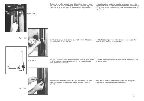
5) Salire di nuovo fino alla parte bassa del carrello ed inserire il cavo,con l’aiuto di una pinza, nel tubo posto alla base del carrello (Fig.43); ilcavo deve uscire di circa 10 cm dal tubo nella parte alta del carrello.5 - Pass the cable up into the lower part of the carriage, then with thehelp of a pliers insert the cable into the tube at the base of the carriage;approx. 10 cm of cable must emerge from the tube at the top of the carriage(Fig.43).Fig.43 - Abb.43Fig.44 - Abb.446) Infilare nel cavo, la vite di registro ed avvitarla nel foro del tubo peruna lunghezza di 20 mm. (Fig.44).6 - Slide the adjusting screw over the cable and screw it into the tubethread for a total length of 20 mm (Fig.44).Fig.45 - Abb.457) Tirare il cavo fino a che la distanza indicata in figura 45 risulta esseredi 32 mm. con una tolleranza massima di +/- 1 mm., quindi fissare ilcavo con il secondo morsetto.7 - Pull the cable out for a length of 32 mm (Fig.45), then secure it withthe second clamp.Assicurarsi che la distanza prevista di 32 mm. sia corretta e, se necessario,effettuare una regolazione fine agendo sulla vite di registro(Fig.46).Check that the length of 32 mm is correct; if not, turn the adjustingscrew until the required length is obtained (Fig.46).Fig.46 - Abb.4642
5 - Remonter le câble jusqu’à la partie inférieure du chariot et, à l’aidede pinces, l’insérer dans le tuyau situé à la base du chariot (Fig.43); àpeu près 10 cm. de câble devront sortir du tuyau du chariot.5 - Das Kabel nun wieder bis zum Unterteil des Schlittens hochziehenund es mit Hilfe einer Zange in das am Schlitten angebrachte Rohrstecken (Abb. 43). Das Kabel muß ca. 10 cm aus den Rohr am Schlittenoberteilaustreten.5 -Subir nuevamente hasta la parte baja del carro e introducir el cable,con la ayuda de un alicate, por el tubo colocado en la base del carro(Fig. 43); el cable debe salir unos 10 cm fuera del tubo en la parte altadel carro.6 - Enfiler le câble dans la vis de réglage et visser celle-ci dans le tuyaufileté pour une longueur de 20 mm (Fig.44).6 - Die Einstellschraube in das Kabel einsetzen und sie ca. 20 cm indas Loch im Rohr einschrauben (Abb.44).6 -Ensartar en el cable el tornillo de ajuste y atornillarlo en el orificio deltubo uno 20 mm. (Fig.44).7 - Tirer le câble jusqu’à ce que la distance ( X ) indiquée à la fig. 45soit égale à 32 mm avec une tolérance maximale de +/- 1 mm, puis assurerle câble à l’aide du deuxième serre-câble.7) Am Kabel ziehen, bis der auf Abb. 45 dargestellte Abstand 32 mmbeträgt (Toleranz max. +/-1 mm); das Kabel dann mit der zweiten Klemmebefestigen.7 -Tirar del cable hasta que la distancia indicada en la figura 45 resulteser de 32 mm. con una tolerancia máxima de +/- 1 mm., después fijar elcable con el segundo terminal.Vérifier que la distance prévue de 32 mm. soit exacte, et, si nécessaire,effectuer un réglage fin en agissant sur la vis de tension (Fig. 46).Kontrollieren, daß der Abstand tatsächlich 32 mm beträgt. Falls erforderlicheine Feineinstellung ausführen, indem auf die Einstellschraubeeingewirkt wird (Abb. 46).Asegurarse que la distancia prevista de 32 mm. sea correcta y, si esnecesario, efectuar un ajuste de precisión accionando sobre el tornillode ajuste (Fig.46).43
- Page 3 and 4: Manuale di istruzioni per l’uso e
- Page 5 and 6: Table des matièresEmballage, trans
- Page 7 and 8: EMBALLAGE, TRANSPORTET STOCKAGELES
- Page 9 and 10: STOCKAGELes emballages devront touj
- Page 11 and 12: LOIS:Directives européennes : 98/3
- Page 13: CHAP.1DESCRIPTION DEL’APPAREILL
- Page 16 and 17: CAP.2SPECIFICHE TECNICHECHAPTER 2SP
- Page 18 and 19: SCHEMA ELETTRICO TRIFASE THREE-PHAS
- Page 20 and 21: TIPI DI VEICOLI SOLLEVABILI E INGOM
- Page 22 and 23: CAP.3SICUREZZACHAPTER 3SAFETYZona o
- Page 24 and 25: PRECAUZIONI GENERALIL’operatore e
- Page 26 and 27: É estremamente importante posizion
- Page 28 and 29: RISCHI DIRETTI ALLE PERSONEIn quest
- Page 30 and 31: RISCHIO DI CADUTA DEL VEICOLO DAL S
- Page 32 and 33: RISCHIO DI FOLGORAZIONEAccanto a pa
- Page 34 and 35: CAP.4INSTALLAZIONECHAPTER 4INSTALLA
- Page 36 and 37: Fig.30 - Abb.30PAVIMENTO fig.30Il s
- Page 38 and 39: MONTAGGIO COLONNE1 - Posizionare la
- Page 40 and 41: 4 - Sollevare la colonna libera sul
- Page 42 and 43: 2 - Sfilare il cavo dalla parte sup
- Page 46 and 47: MONTAGGIO BRACCI E DISPOSITIVI DI B
- Page 48 and 49: 974 - (Fig.50) Inserire il perno sp
- Page 50 and 51: 18) Avvitare i piattelli (1) alle e
- Page 52 and 53: A + 2 cm.ATTENZIONE5 - Per assicura
- Page 54 and 55: 400V230VALLACCIAMENTO IMPIANTO ELET
- Page 56 and 57: CAP.5 FUNZIONAMENTO ED USOI comandi
- Page 58 and 59: Cap.6MANUTENZIONECHAPTER 6MAINTENAN
- Page 60 and 61: Fig.63 - Abb.63MANUTENZIONE PERIODI
- Page 62 and 63: Verificare, con chiave dinamometric
- Page 64 and 65: CAP.7INCONVENIENTI E RIMEDICHAPTER
- Page 66 and 67: APPENDICE A INFORMAZIONIDEMOLIZIONE
- Page 68 and 69: COLONNE E BASAMENTOPOSTS AND BASES
- Page 70 and 71: QUADRO ELETTRICOCONTROL PANELSCHALT
- Page 72 and 73: B0052XX CARRELLO COLONNA MOTORE MOT
- Page 74 and 75: B1278XX COLONNA MOTORE ‘07 MOTOR
5) Salire di nuovo fino alla parte bassa <strong>de</strong>l carrello ed inserire il cavo,con l’aiuto di una pinza, nel tubo posto alla base <strong>de</strong>l carrello (Fig.43); ilcavo <strong>de</strong>ve uscire di circa 10 cm dal tubo nella parte alta <strong>de</strong>l carrello.5 - Pass the cable up into the lower part of the carriage, then with thehelp of a pliers insert the cable into the tube at the base of the carriage;approx. 10 cm of cable must emerge from the tube at the top of the carriage(Fig.43).Fig.43 - Abb.43Fig.44 - Abb.446) Infilare nel cavo, la vite di registro ed avvitarla nel foro <strong>de</strong>l tubo peruna lunghezza di 20 mm. (Fig.44).6 - Sli<strong>de</strong> the adjusting screw over the cable and screw it into the tubethread for a total length of 20 mm (Fig.44).Fig.45 - Abb.457) Tirare il cavo fino a che la distanza indicata in figura 45 risulta esseredi 32 mm. con una tolleranza massima di +/- 1 mm., quindi fissare ilcavo con il secondo morsetto.7 - Pull the cable out for a length of 32 mm (Fig.45), then secure it withthe second clamp.Assicurarsi che la distanza prevista di 32 mm. sia corretta e, se necessario,effettuare una regolazione fine agendo sulla vite di registro(Fig.46).Check that the length of 32 mm is correct; if not, turn the adjustingscrew until the required length is obtained (Fig.46).Fig.46 - Abb.4642


