IAttenzione - Wertherint.de
IAttenzione - Wertherint.de
IAttenzione - Wertherint.de

Create successful ePaper yourself
Turn your PDF publications into a flip-book with our unique Google optimized e-Paper software.
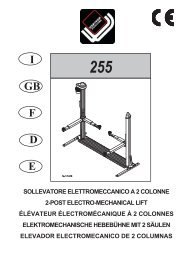
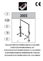
Lato comandoCommand si<strong>de</strong>Côté comman<strong>de</strong>SteuerseiteLado mandoLato posterioreRear si<strong>de</strong>Côté arrièreRückseiteLado posteriorLato servizioService si<strong>de</strong>Côté serviceService-SeiteLado servicioCAP.1. DESCRIZIONE DELLAMACCHINAIl sollevatore elettromeccanico a 2 colonne è fisso, cioè ancorato al suoloed è progettato e costruito per il sollevamento e lo stazionamento inquota di autoveicoli e furgoni.Il sollevatore è composto, principalmente da :- gruppo struttura fissa ( basamento + colonne)- gruppi di sollevamento ( carrello + bracci )- gruppo di trasmissione- quadro comando- sicurezze.In figura 4 sono indicate le varie parti che compongono il sollevatore ele zone di lavoro consentite e riservate al personale ad<strong>de</strong>tto, attorno alsollevatore stesso.CHAPTER 1.MACHINEDESCRIPTION OF THE2 post electro-mechanical lift is anchored to the ground, and is <strong>de</strong>signedand manufactured for lifting vehicles and vans and holding themin an elevated position.The lift mainly comprises:- fixed structural unit (base and post)- lifting unit (carriage and arms)- transmission unit- control panel- safety <strong>de</strong>vices.Figure 4 illustrates the various parts making up the lift, as well as thepermitted work areas reserved for authorised personnel around the machine.Lato anterioreFront si<strong>de</strong>Côté avantVor<strong>de</strong>rseiteLado anteriorLato comando: è il lato <strong>de</strong>l sollevatore che compren<strong>de</strong> la zona riservataall’operatore in cui si acce<strong>de</strong> al quadro comandiLato servizio: è il lato opposto a quello comando.Lato anteriore: è il lato braccio lungo.Lato posteriore: è il lato braccio corto.Command si<strong>de</strong>: the si<strong>de</strong> of the rack which inclu<strong>de</strong>s the area reservedfor the operator with access to the control panelService si<strong>de</strong>: the si<strong>de</strong> opposite to the command si<strong>de</strong>.Front: long arm si<strong>de</strong>.Rear: short arm si<strong>de</strong>.Fig.4 - Abb.43214GRUPPO STRUTTURA FISSA (Fig.5)E’ costituito da : Un Basamento (1) costruito in tubi di acciaio saldati, con fori per il fissaggioal suolo mediante tasselli ad espansione (ve<strong>de</strong>re cap.4“Installazione“) e bussole con foro filettato per il fissaggio tramite bullonatura<strong>de</strong>lla piastra di base <strong>de</strong>lla colonna.All’interno <strong>de</strong>l basamento è posizionata la catena a rulli (2) che trasmetteil moto dalla colonna motore (3) alla colonna servizio (4).Nella parte superiore <strong>de</strong>l basamento è fissata una pedana mobile (5)di copertura in lamiera striata . 2 Colonne in lamiera di acciaio piegata alla cui base è saldata unapiastra forata per il fissaggio al basamento mediante bullonatura.All’interno di ogni colonna si trovano i gruppi mobili di sollevamento<strong>de</strong>ll’automezzo.FIXED STRUCTURE GROUP (Fig.5)Comprises: Base (1) ma<strong>de</strong> of wel<strong>de</strong>d steel tubes, with holes for anchoring to theground by screw anchors (see Chap. 4 “ Installation “) and busheswith threa<strong>de</strong>d holes for bolting on the post baseplates.A roller chain (2) is located insi<strong>de</strong> the base to transmit drive from themotor post (3) to the service post (4).A base cover plates (5) in chequered steel it’s fixed to the upper partof the base. 2 pressed steel plate posts, with wel<strong>de</strong>d baseplate pre-drilled for boltingto un<strong>de</strong>rlying structure.Each post houses the mobile units for lifting the vehicle.5Fig.5 - Abb.510