Manuel d'utilisation K-114 - Keller AG
Manuel d'utilisation K-114 - Keller AG
Manuel d'utilisation K-114 - Keller AG

You also want an ePaper? Increase the reach of your titles
YUMPU automatically turns print PDFs into web optimized ePapers that Google loves.
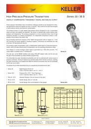
BetriebsanleitungSchnittstellenkonverter K-<strong>114</strong>Manual interface converter K-<strong>114</strong> Page 15<strong>Manuel</strong> du convertisseur K-<strong>114</strong> Page 29
InhaltsverzeichnisAllgemeinesAllgemeines 3Steckerbelegung der Konverter bzw. Anschlüsse 4Technische Spezifikationen 4Beschreibung 5Typische Anwendung 5Produktübersicht 5Systemvoraussetzungen Software K-<strong>114</strong>_Config 6Werkskonfiguration K-<strong>114</strong> 6Funktionsübersicht K-<strong>114</strong> 6LED Anzeige 7RoHS 8Entsorgung 8Hilfestellung zur Fehleranalyse 9Software K-<strong>114</strong>_Config installieren 10Software K-<strong>114</strong>_Config ausführen 10Spannungs- und Strommessungen mit K-<strong>114</strong>_Config 11Warnungen und Hinweise in der Software 12Support bekommen 13Messdaten K-<strong>114</strong> aufzeichnen 14Konformitätserklärung 43Der Schnittstellenkonverter K-<strong>114</strong> dient zur Umsetzung eines USB-Signals auf ein serielles RS485-Halbdublexsignalzum Anschluss an jeden beliebigen Computer mit USB-Port. Der Konverter K-<strong>114</strong> und die angeschlossenenEndverbraucher werden über den USB-Anschluss versorgt. Für den Betrieb mehrerer Endverbraucher wird einNetzteil zugeschaltet. Der Konverter K-<strong>114</strong> wird vorzugsweise bei KELLER Produkten verwendet.Der Schnittstellenkonverter K-<strong>114</strong> ermöglicht Ihnen……die Umsetzung eines USB-Signals auf RS485 (half dublex)…das Messen angelegter Signalspannung (0...12 VDC)z.B. Ausgangssignalspannung von einem Drucktransmitter…das Messen der Stromaufnahme angeschlossener Endverbraucher im Bereich 0...40 mAz.B. Stromaufnahme angeschlossener Endverbraucher oder Strom-Ausgangssignalvon einem DrucktransmitterDer Schnittstellenkonverter K-<strong>114</strong> bietet Ihnen……optische Status- und Konfigurationsanzeige (LED)…galvanische Trennung zwischen Computer und Konverter…Tools zur DiagnoseK-<strong>114</strong> K-<strong>114</strong>A K-<strong>114</strong>B– 3 –
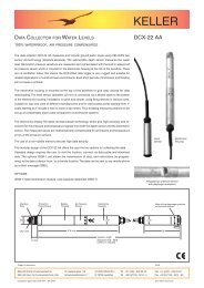
Steckerbelegung der Konverter bzw. AnschlüsseBeschreibungK-<strong>114</strong>Schraubsteckklemme+Vcc RS GND RS485-A 485-BK-<strong>114</strong>AFischer SteckverbinderS 103 A054-1302: +U-IN1: GND5: RS485-B3: +Vcc4: RS485-AK-<strong>114</strong>BBinder KabeldoseSerie 680 (female) 5-Pol3: +Vcc2: +U-IN4: RS485-A1: GND5: RS485-BDer K-<strong>114</strong> kommuniziert mit den angeschlossenen Geräten über einen RS485 (half dublex mode) Bus. Die amK-<strong>114</strong> angeschlossenen Geräte werden über den USB-Ausgang des PC’s oder über ein externes Netzteil (Buchsedes K-<strong>114</strong>) versorgt.KELLER Produkte arbeiten mit „Fail-Save Treibern“ welche bei kurzgeschlossenen, offenen oder terminiertenEingängen, ein logisches „High“ am Empfangsausgang ausgeben um ungültige Signalzustände zu meiden. Zudemverfügen KELLER Produkte über eine „Slew-Rate-Limitierung“ welche die Flankensteilheit des Treiber Ausgangeslimitiert. Dadurch werden Hochfrequenz Emissionen von Geräten und Datenleitungen vermieden. An diesemRS485-Master können bis maximal 128 Busteilnehmer angeschlossen werden.Technische SpezifikationenTypische AnwendungSymbol Parameter Bedingung Min. typ. Max. EinheitStromaufnahme K-<strong>114</strong> ohne Endverbraucher 30 43 55 mALeistungsaufnahme K-<strong>114</strong> ohne Endverbraucher 150 215 275 mWVersorgung Endverbraucher U-Out ohne Netzteil 11,2 11,8 12,5 VDCVersorgung Endverbraucher I-Out mit Netzteil – – 150 mAExterne Versorgung Netzteil 12 15 20 VDCSpannungseingang U-In K-<strong>114</strong>A / K-<strong>114</strong>B 0 12 VDCGenauigkeit Spannungseingang U-In R I ≥ 30 kΩ 0,2 0,3 %FSStrommessung I-Out 0 40 m<strong>AG</strong>enauigkeit Strommessung I-Out 0,2 0,3 %FSDaten-Übertragungsrate slow max. Absetzdistanz ≤ 1 km – – 250 kbpshigh max. Absetzdistanz ≤ 20 km – – 20 MbpsGerät K-<strong>114</strong> Schutzgrad IP 40 – – –Gerätesicherung (USB) F1 ohne Netzteil 0,5 ALager- und Betriebstemperatur -10 20 50 °CProduktübersichtProdukt Anschluss Produktnummer unterstützte ProdukteK-<strong>114</strong> Schraubsteckklemmen 309010.0074 alle digitalen KELLER Produkte Serie 3X, Serie 4X, DCX*K-<strong>114</strong>A Fischer Stecker 309010.0075 DCX-16 /-22-25 PVDF / -38, LEO Record, LEX 1, Serie GSMK-<strong>114</strong>B Binder Kabeldose 309010.0076 Serie 30X / 40X, LEO 3, EV-120, dV-22 PP, dV-2 PS**, Castello**K-<strong>114</strong>M M12 Kabeldose 309010.0077 nur DCX-18 (Kommunikations- und Ladekabel)* ohne Spannungseingang** benötigt zusätzliche Kabeloption– 4 – – 5 –
Systemvoraussetzungen Software K-<strong>114</strong>_ConfigProzessormin. Pentium 75 MHzBildschirmauflösung min. 1024 x 768Arbeitsspeichermin. 16 MB RAMFreier Festplattenspeicher min. 20 MB empfohlenInternetverbindung empfohlen(für Support notwendig)BetriebssystemWindows XPWindows 7Funktionsübersicht K-<strong>114</strong>Werkskonfiguration K-<strong>114</strong>Busadresse KonverterBaudrateEcho offBias NetzwerkTerminationHigh Speed253 (nicht änderbar)9600 baudausausausausDiese Einstellungen werden generell für denstörungsfreien Betrieb von KELLER Produktenempfohlen.LED AnzeigeK-<strong>114</strong> USB to RS485 ConverterRS485BPowerRX/TX GNDRS485A+VCCUSBRS485PowerBetriebsbereitschnelles Blinken, Fehler ➞ U-USB < 4,5 VDC ➞ Netzteil anschliessenlangsames Blinken, Fehler ➞ U-UOUT < 11,2 VDC ➞ Netzteil anschliessenFehlerwww.keller-druck.comExternal SupplyEchooffBiason15 VDC GNDTermination High Speedon onU-USBUSBEchoBiasRX/TXZeigt den Status der Sendeleitung TX und Empfangsleitung RXRS485TerminationBiasHigh SpeedTX, Sendet Daten über den RS485 BusRX, Empfängt Daten über den RS485 BusEcho offDie vom PC gesendeten Daten (TX) werden vom PCnicht empfangen.Bias NetzwerkVermeidet undefinierte Buspegel bei inaktiven Leitungstreibern.➞ Höhere StörsicherheitTerminationVermeidet Reflektionen auf den Signalleitungen.– 6 –High SpeedDeaktiviert die „Slew-Rate Limitierung“ des RS485Treibers.Dadurch kann mit höheren Übertragungsgeschwindigkeiten(> 250 kbps) kommuniziert werden. DerStandardmodus < 250 kbps mindert, im Gegensatzzum „High Speed Mode“, Reflektionen auf den Signalleitungenund weist ein besseres EMV-Verhalten aus.Geräte von KELLER arbeiten mit Übertragungsgeschwindigkeiten< 250 kbps, weshalb diese Funktionwerkseitig nicht aktiviert wird.Echo offZeigt den Status der Funktion Echo offEcho off deaktiviert (➞ Echo eingeschaltet)Echo off aktiv (➞ Echo ausgeschaltet)Bias onZeigt den Status der Funktion Bias on**Bias Widerstände (560 Ω) für RS485A und B aktiviert.keine Bias Widerstände zugeschaltet– 7 –
KELLER Produkte benutzen „Fail-Save“ RS485 Treiber, welche auch bei undefinierten Pegel ein gültiges Signalausgeben. Deshalb muss diese Funktion nicht zwingend aktiviert werden.Hilfestellung zur FehleranalyseTermination onTerminationswiderstand 120 Ω zugeschaltet**Terminationswiderstand nicht zugeschaltetHigh SpeedZeigt den Status der Funktion High Speed**High Speed aktiviertHigh Speed deaktiviert**ACHTUNG: Bei batteriebetriebenen Geräten kann diese Funktion zu Fehlverhalten führen.➞ Empfehlung: Funktion nicht aktivierenRoHSDieses Produkt erfüllt die EG-Richtlinie 2002/95/EG zur Beschränkung der Verwendung bestimmtergefährlicher Stoffe in Elektro- und Elektronikgeräten.EntsorgungDas Produkt darf am Ende seiner Nutzungsdauer nicht über den normalen Hausmüll entsorgtwerden. Zur Vermeidung möglicher Umwelt- oder Gesundheitsschäden durch unkontrollierteMüllentsorgung muss dieses Produkt von anderen Abfällen getrennt und ordnungsgemässrecycelt werden, um den nachhaltigen Gebrauch der Rohstoffe zu gewährleisten.aus / rotLED aus:➞ Verbindungskabel undVersorgung prüfenLED rot:➞ Softwaretreiberprüfen / installierenLED ausComport wird bereits benutzt➞ falsche Comportnummergewählt (Auswahl ändern)➞ andere Software benutztden Comport –alle Softwareprogrammeschliessen➞ Verdrahtung EndverbraucherprüfenLEDPOWERgrünLEDRX / TXflackertblinkt grünVersorgungsspannungunter Minimum➞ Fremdversorgung überNetzteil➞ LeistungsaufnahmeVerbraucher prüfenleuchtet permanentBusfehler➞ Verdrahtung Endverbraucherprüfen➞ Trennen Sie alle an denK-<strong>114</strong> angeschlossenenGeräte➞ Spannungspegel RS485prüfen, ggf. FunktionTermination oder Biasaktivieren– Baudrateneinstellungen / Geräteadressen prüfen– K-<strong>114</strong> auf Werkseinstellungen zurücksetzen– Support anfordern– 8 –– 9 –
Software K-<strong>114</strong>_Config installierenSpannungs- und Strommessungen mit K-<strong>114</strong>_ConfigInstallieren Sie zuerst den Driver K-104 / K-<strong>114</strong> auf Ihrem Computer und führen Sie anschliessend die SoftwareK-<strong>114</strong>_Config aus. (Software CD im Lieferumfang oder kostenloser Download unter www.keller-druck.com)Software K-<strong>114</strong>_Config ausführenFühren Sie K-<strong>114</strong>_Config aus und wählen Sie den entsprechenden COM Port aus. Wechseln Sie anschliessend zurAnsicht K-<strong>114</strong> Configuration (oben rechts).Tipp: Bei geöffnetem Programm wird der Comport automatisch selektiert, sobald der K-<strong>114</strong> am Computer eingestecktwird.Nr. Symbol Funktion Beschreibung1 I-OUT Versorgungsstrom externer Verbraucher Während Betrieb mit externer Stromversorgung keine gültige Anzeige2 U-USB Versorgungsspannung USB3 U-OUT Versorgungsspannung externerZugeschaltete Spannungsversorgung wird über U-OUT angezeigtVerbraucher4 U-IN Spannungseingang Bereich 0…12 VDC– 10 –– 11 –
List of contentsGeneral informationGeneral information 17Pin assignment for converter / connections 18Technical specifications 18Description 19Typical application 19Overview of products 19System requirements for K-<strong>114</strong>_Config software 20Factory configuration for the K-<strong>114</strong> 20Functional overview for the K-<strong>114</strong> 20LED display 21RoHS 22Disposal 22Help with fault analysis 23Installing the K-<strong>114</strong>_Config software 24Running the K-<strong>114</strong>_Config software 24Voltage and current measurements with K-<strong>114</strong>_Config 25Warnings and other messages in the software 26Getting support 27Recording K-<strong>114</strong> measurement data 28EC-Declaration of Conformity 43The K-<strong>114</strong> interface converter is used to convert a USB signal to a serial RS485 half-duplex signal, for connectionto any desired computer with a USB port. The K-<strong>114</strong> converter and the connected transmitters are powered via theUSB connection. An external power supply unit can also be connected to power multiple instruments. The K-<strong>114</strong>converter is preferred for use with KELLER products.With the K-<strong>114</strong> interface converter, you can……convert a USB signal to RS 485 (half-duplex)…measure the applied signal voltage (0...12 VDC)e.g. the output signal voltage from a pressure transmitter…measure the power consumption of connected end consumers in the 0...40mA rangee.g. the power consumption of connected end consumers orthe power output signal from a pressure transmitterThe K-<strong>114</strong> interface converter offers you……visual status and configuration displays (LED)…electrical isolation between the computer and the converter…diagnostic toolsK-<strong>114</strong> K-<strong>114</strong>A K-<strong>114</strong>B– 17 –
System requirements for K-<strong>114</strong>_Config softwareProcessormin. Pentium 75 MHzScreen resolution min. 1024 x 768Main (working) memory min. 16 MB RAMFree hard disk space min. 20 MB(recommended)Internet connection recommended(required for support)Operating systemWindows XPWindows 7Factory configuration for the K-<strong>114</strong>Converter bus address 253(cannot be changed)Baud rate9600 baudEcho offoffBias networkoffTerminationoffHigh SpeedoffThese settings are generally recommended to ensuretroublefree operation of KELLER products.LED displayPowerK-<strong>114</strong> USB to RS485 ConverterRS485BPowerRX/TX GNDRS485A+VCCUSBRS485Ready to operateFlashing rapidly, error ➞ U-USB < 4,5 VDC ➞ Connect power supply unitFlashing slowly, error ➞ U-UOUT < 11,2 VDC ➞ Connect power supply unitErrorwww.keller-druck.comExternal SupplyEchooffBiason15 VDC GNDTermination High Speedon onFunctional overview for the K-<strong>114</strong>U-USBRX/TXUSBEchoRS485BiasTerminationHigh SpeedShows the status of the transmission line (TX) and the reception line (RX).TX, sending data via the RS485 busRX, receiving data via the RS485 busBiasEcho offData sent from the PC (TX) aren’t received by the PC.Bias networkPrevents undefined bus levels when line drivers are inactive.➞ Greater immunity to interferenceTerminationPrevents reflections on the signal lines.– 20 –High SpeedDisables the RS485 driver’s slew-rate limitation.This allows communication at higher transmissionspeeds (> 250 kbps). Unlike high speed mode, thestandard mode (< 250 kbps) reduces reflections onthe signal lines and provides better EMC behaviour.KELLER devices operate at transmission speeds< 250 kbps, so this function is not activated ex factory.Echo offShows the status of the Echo off function.Echo off disabled (➞ echo switched on)Echo off enabled (➞ echo switched off)Bias onShows the status of the Bias on function.**Bias resistors (560 Ω) for RS485A and B are enabledNo bias resistors are connected– 21 –
A importância dos ácidos graxos ω-3 e ω-6 para a prevenção de doenças e na saúde humana18. American heart association. Dietary Guidelines for Health American Adults, 2001.Disponível em: http://www.americanheart.erg/Heart_and_Stroke_A_Z_Guide /dietg. html.>Acesso em: 12 jul. 200519. Department of health. Report of the working group on diet and cancer of the committeeon medical aspects of food and nutrition policy. Nutritional aspects of cardiovascular disease.The Stationary Office, London; 1994.20. Gibney MJ, Hunter B. The effects of short-and long-term supplementation with fishoil on incorporation of n-3 polyunsaturated fatty acids into cells of the immune system inhealthy volunteers. Eur J Clin Nutr. 1993; 47:255–259.21. Wachira AM, Sinclair LA, Wilkinson, Enser M, Wood JD, Fisher AV. Effects of dietary fatsource and breed on the carcass composition, n-3 polyunsaturated fatty acid and conjugatedlinoleic acid content of sheep meat and adipose tissue. Br J Nutr 2002; 88(6):697–709.22. Calder PC, Grimble RF. Polyunsaturated fatty acids, inflammation and immunity. Eur JClin Nutr 2002; 56 (Suppl. 1):14–9.23. Health and welfare canada. Scientific Review Committee: Nutrition recommendations.Canadian Government Publishing Center. Ottawa: ON; 1990.24. IFFO - Internacional Fishmeal And Fish Oil Organisation. Impact of fish farming onfish stocks. 2002. [Citado em: 2005 ago 13]. Disponível em: http://www.iffo.org.uk/tech/bordeaux.htm25. Saynor R, Verel D, Gillott T. The long term effect of dietary supplementation with fishlipid concentrate on serum lipids, bleeding time, platelets and angina. Atherosclerosis 1984;50:3–10.26. Dehmer GJ et al. Reduction in the rate of early restenosis after coronary angioplasty bya diet supplemented with n-3 fatty acids. N Engl J Med. 1988; 319(12):733–40.27. Miller GJ, Martin JC, Mitropoulus, Reeves BGA, Thompson RL, Meade TW et al.Plasma factor VII is activated by postprandial triglyceridemia, irrespective of dietary fatcomposition. Atherosclerosis 1991; 86(2-3):163–71.28. Carmelli D, Cardon LR, Fabsitz R. Clustering of hypertension, diabetes, and obesity inadult male twins: same genes or same environments. Am J Hum Genet 1994; 55(3):566–73.29. Borkman M, Storlien LH, Pan DA, Jenkins AB, Chisholm DJ, Campbell LV. The relationbetween insulin sensitivity and the fatty acid composition of skeletal-muscle phospholipids.N Engl J Med 1993; 328(4):238–44.30. Harris WS. Do ω-3 fatty acids worsen glycemic control in NIDDM? ISSFAL Newsletter1996; 3:6–9.86Revista Salus-Guarapuava-PR. Jan./Jun. 2008; 2(1)
Installing the K-<strong>114</strong>_Config softwareVoltage and current measurements with K-<strong>114</strong>_ConfigFirst, install the K-104 / K-<strong>114</strong> driver on your computer and then run the K-<strong>114</strong>_Config software.(The software CD is included with purchase or can be downloaded free of charge at www.keller-druck.com)Running the K-<strong>114</strong>_Config softwareRun K-<strong>114</strong>_Config and select the appropriate COM port. Then go to the K-<strong>114</strong> Configuration view (top right).Tip: When the program is open, Comport is selected automatically as soon as the K-<strong>114</strong> is plugged into the computer.No. Symbol Function Description1 I-OUT Current supply – external consumer No valid display during operation with external current supply2 U-USB USB voltage supply3 U-OUT Voltage supply – external consumer Switched-in voltage supply is indicated via U-OUT4 U-IN Voltage input Range: 0...12 VDC– 24 –– 25 –
Warnings and other messages in the softwareU-IN outside of measurement rangeThe U-IN measurement range is from 0...12 VDC. The exclamation mark warns you that the upper limit of themeasuring range that can be displayed (> 16 VDC) has been reached.The voltage for measurement that is actually applied (U-IN) can therefore be greater than the value for U-IN thatis displayed.Connect power supply unitIf the difference between U-OUT and U-IN is less than 3 VDC, the „Connect power supply unit“ message appears.Getting supportU-USB is below minimumThis message appears if the U-USB voltage is below 4.8 VDC. Fault-free functioning of the converter is no longerguaranteed. Supply the converter from an external power supply unit.U-OUT outside of rangeThis message appears if U-OUT is less than 11.2 VDC. Supply the converter from an external power supply unit.If faults or errors occur while you are working with the converter, use the Help with fault analysis section to rectifythe problem. If problems persist after you have worked through this section, you can request assistance fromKELLER by telephone. For contacts, visit: www.keller-druck.comThe „Download remote maintenance software“ function automatically launches the download of a Remote DesktopProgram. Once the download has completed, run the program. After you enter the connection code, our technicalsupport team will log into your computer and offer you on-the-spot help directly on your screen.– 26 –– 27 –
Recording K-<strong>114</strong> measurement dataThe values measured for I-OUT, U-IN, U-OUT and U-USB can be recorded and saved via Software ControlCenter-Series30 (CCS30). (Read the CCS30 manual on this subject.)To view the K-<strong>114</strong> controller’s measured values via the software, you must enter bus address 253 in the CCS30 andlet the device search. Use the „New measurement“ function key to view and save the measurement data.<strong>Manuel</strong>du convertisseur K-<strong>114</strong>– 28 –
Table des MatièresGénéralitésGénéralités 31Affectation des broches des connecteurs et du bornier à vis 32Spécifications techniques 32Description 33Application typique 33Liste de produits 33Conditions préalables du système pour la configuration 34du logiciel K-<strong>114</strong>_ConfigConfiguration d’usine du K-<strong>114</strong> 34Aperçu du fonctionnement du K-<strong>114</strong> 34Affichages par LED 35RoHS 36Mise au rebut 36Graphique de diagnostic de défauts 37Installation du logiciel K-<strong>114</strong>_Config 38Lancement du logiciel K-<strong>114</strong>_Config 38Mesures de tension et de courant avec K-<strong>114</strong>_Config 39Alertes et instructions émises par le logiciel 40Obtenir de l’aide 41Enregistrement des données de mesure K-<strong>114</strong> 42Déclaration CE de conformité 43Le convertisseur K-<strong>114</strong> sert à transformer un signal USB en un signal semi-duplex sériel RS485 afin de permettrele raccordement d’appareils à tout ordinateur disposant d’un port USB. Le convertisseur K-<strong>114</strong> et les appareilsconnectés sont alimentés électriquement par le port USB. Si le nombre d’appareils est important, le convertisseurdoit être raccordé à un bloc d’alimentation. Le convertisseur K-<strong>114</strong> doit être privilégié pour le raccordement desproduits KELLER.Le convertisseur K-<strong>114</strong> permet……la conversion d’un signal USB en RS 485 (semi-duplex)…la mesure d’une tension appliquée (0...12 VDC)p. ex. tension du signal de sortie d’un transmetteur de pression…la mesure sur une plage de 0…40 mA du courant absorbé par les appareils connectésp. ex. courant consommé par les transmetteurs de pression connectés ou encore courant du signal de sortied’un transmetteur de pressionLe convertisseur K-<strong>114</strong> dispose……d’une signalisation des états et des configurations (LED)…de l’isolement électrique entre l’ordinateur et le convertisseur…d’outils de diagnosticK-<strong>114</strong> K-<strong>114</strong>A K-<strong>114</strong>B– 31 –
Affectation des broches des connecteurs et du bornier à visK-<strong>114</strong>Bornier à vis+Vcc RS GND RS485-A 485-BSpécifications techniquesK-<strong>114</strong>AConnecteur FischerS 103 A054-1302: +U-IN1: GND5: RS485-BK-<strong>114</strong>BConnecteur rond BinderSérie 680 (femelle) 5 broches3: +Vcc2: +U-IN4: RS485-A5: RS485-BSymbole Paramètre Condition Min. Typ. Max. UnitéCourant consommé par le K-<strong>114</strong> Sans appareil connecté 30 43 55 mAPuissance absorbée par le K-<strong>114</strong> Sans appareil connecté 150 215 275 mWTension d’alimentation disponible U-Out Sans alimentation externe 11,2 11,8 12,5 VDCCourant d’alimentation disponible I-Out Avec alimentation externe – – 150 mAAlimentation externe Bloc d’alimentation 12 15 20 VDCTension d’entrée mesurable U-In Uniquement versions K-<strong>114</strong>A / K-<strong>114</strong>B 0 12 VDCPrécision tension d’entrée U-In R I ≥ 30 kΩ 0,2 0,3 %FSMesure de courant I-Out Uniquement sans alimentation externe 0 40 mAPrécision de la mesure de courant I-Out 0,2 0,3 %FSDébit de transmission de données slow Distance max. de transmission ≤ 1 km – – 250 kbpshigh Distance max. de transmission ≤ 20 km – – 20 MbpsEtanchéité IP 40 – – –Fusible de protection (USB) F1 Sans alimentation externe 0,5 ATemp. de fonctionnement et de stockage -10 20 50 °C3: +Vcc4: RS485-A1: GNDDescriptionLe K-<strong>114</strong> communique avec les appareils raccordés par une interface RS485 (en mode semi-duplex). Les équipementsraccordés au K-<strong>114</strong> sont alimentés par la sortie USB de l’ordinateur ou encore par un bloc secteur extérieur(branché sur le connecteur du K-<strong>114</strong>).Les produits KELLER travaillent avec des « drivers autoprotégés » qui émettent un signal logique« haut » sur la ligne de réception pour éviter des signalisations erronées si les entrées sont en courtcircuit,en circuit ouvert ou pontées par une terminaison. De plus, les produits KELLER sont pourvus d’une« limitation de la vitesse de balayage » pour limiter le front de montée du signal de sortie du driver. Cecipermet d’éviter des émissions de signaux haute fréquence par les appareils connectés et les lignes dedonnées. Le module RS485 maître peut gérer jusqu’à 128 appareils connectés au bus de communication.Application typiqueListe de produitsProduit Raccordement N° de référence Equipements raccordablesK-<strong>114</strong> Bornier à vis 309010.0074 Tous produits numériques KELLER Série 3X, Série 4X, DCX*K-<strong>114</strong>A Connecteur Fischer 309010.0075 DCX-16 /-22-25 PVDF / -38, LEO Record, LEX 1, Série GSMK-<strong>114</strong>B Connecteur rond Binder 309010.0076 Série 30X / 40X, LEO 3, EV-120, dV-22 PP, dV-2 PS**, Castello**K-<strong>114</strong>M Embase M12 309010.0077 Uniquement DCX-18 (câble de transmission et de charge)* raccordable uniquement par le bus RS485(Raccordement par la sortie analogique impossible, même lorsque celle-ci est disponible sur l’appareil connecté)** nécessite une option câble supplémentaire– 32 – – 33 –
Conditions préalables du système pour laconfiguration du logiciel K-<strong>114</strong>_ConfigProcesseurPentium 75 MHz min.Résolution d’écran 1024 x 768 min.Mémoire de travail16 MB RAM min.Espace libre sur disque dur 20 MB min.recommandésLiaison Internetrecommandée(nécessaire pourl’assistance technique)Système d’exploitation Windows XPWindows 7Configuration d’usine du K-<strong>114</strong>Adresse bus du convertisseur 253(non modifiable)Débit de transmission 9600 baudEcho offoffBias réseauoffRésistance de terminaison offHaut débitoffCes réglages sont généralement recommandés pourun fonctionnement sûr des produits KELLER.Affichages par LEDPowerK-<strong>114</strong> USB to RS485 ConverterRS485BPowerRX/TX GNDRS485A+VCCUSBRS485prêt à fonctionnerclignotement rapide, défaut ➞ U-USB < 4,5 VDC ➞ brancher un bloc d’alimentationclignotement lent, défaut ➞ U-UOUT < 11,2 VDC ➞ brancher un bloc d’alimentationdéfautwww.keller-druck.comExternal SupplyEchooffBiason15 VDC GNDTermination High Speedon onAperçu du fonctionnement du K-<strong>114</strong>U-USBBiasUSBEchoTerminaisonEvite les réflexions sur les lignes de transmission dessignaux.RX/TXIndique l’état de la ligne d’émission TX et de la ligne de réception RXTX, émet des données par le bus RS485RX, reçoit des données par le bus RS485RS485TerminationBiasHigh SpeedEcho offLes données émises par le PC (TX) ne sont pasreçues par le PC.Bias réseauEmpêche l’apparition d’un niveau de bus indéfinilorsque les drivers sont inactifs. ➞ Sécurité accruecontre les perturbations– 34 –Haut débitDésactive la limitation de « vitesse de balayage » dudriver RS485.Ceci permet de communiquer à des débits de transmissionplus élevés (> 250 Kb/s). Le mode Standard< 250 Kb/s, contrairement au mode « Haut débit »,réduit les réflexions sur les lignes de transmission etprésente un meilleur comportement en environnementélectromagnétique perturbé.Les équipements KELLER travaillent à des vitessesde transmission < 250 Kb/s, ce qui explique que cettefonction n’est pas activée lors du réglage en usine.Echo offIndique l’état de la fonction Echo off.Echo off désactivé (➞ Echo actif)Echo off activé (➞ Echo inactif)Bias onIndique l’état de la fonction Bias on**résistances de Bias (560 Ω) pour RS485A et B activeaucune résistance de Bias en service– 35 –
Installation du logiciel K-<strong>114</strong>_ConfigMesures de tension et de courant avec K-<strong>114</strong>_ConfigInstaller tout d’abord le pilote K-104 / K-<strong>114</strong> sur l’ordinateur puis lancer le logiciel K-<strong>114</strong>_Config.(Le logiciel se trouve sur le CD-ROM fourni ou peut être téléchargé gratuitement à l’adresse www.keller-druck.com)Lancement du logiciel K-<strong>114</strong>_ConfigExécuter le programme K-<strong>114</strong>_Config et sélectionner le port COM correspondant. Ouvrir ensuite l’onglet K-<strong>114</strong> Configuration(en haut à droite).Astuce : lorsque le programme est ouvert, le port de communication est automatiquement sélectionné dès que leconvertisseur K-<strong>114</strong> est branché à l’ordinateur.N° Symbole Fonction Description1 I-OUT Courant d’alimentation des appareils connectés Ne fonctionne pas si une alimentation externe est branchée2 U-USB Tension d’alimentation USB3 U-OUT Tension d’alimentation des appareils connectés La tension d’alimentation des appareils raccordés est affichéesous U-OUT.4 U-IN Tension d’entrée (sortie de l’appareil connecté) Plage 0…12 VDC– 38 –– 39 –
Alertes et instructions émises par le logicielU-IN hors plage de mesureLa plage de mesure U-IN se situe entre 0 et 12 VDC. Toutefois, l’affichage peut être assuré jusqu’à environ16 VDC, sans aucune garantie de précision. Le point d’exclamation attire l’attention sur le fait que la limite supérieurede la plage de mesure affichable (> 16 VDC) a été atteinte. La tension de mesure U-IN effectivement appliquéeest supérieure à la valeur U-IN affichée.Raccordement d’un bloc d’alimentationLorsque la différence entre U-OUT et U-IN est inférieure à 3 VDC, l’écran affiche le message « Raccorder unealimentation externe ».Obtenir de l’aideU-USB inférieure à la valeur minimaleCe message apparaît lorsque la tension U-USB chute au-dessous de 4,8 VDC. Le fonctionnement correct duconvertisseur n’est alors plus garanti. Le convertisseur doit être raccordé à un bloc d’alimentation externe.U-OUT hors plageCe message apparaît lorsque la tension U-OUT est inférieure à 11,2 VDC. Le convertisseur doit être raccordé à unbloc d’alimentation externe.– 40 –Lorsque le fonctionnement du convertisseur présente des anomalies, se reporter au Graphique de diagnostic dedéfauts afin de corriger le défaut. Si des difficultés subsistent après analyse de toutes les hypothèses envisageables,il est alors possible d’obtenir de l’aide par téléphone auprès de KELLER. Contact : www.keller-druck.com.La fonction « Téléchargement du logiciel de maintenance à distance » lance automatiquement le téléchargementd’un programme de prise en main du bureau à distance. Lancer ce programme dès que le téléchargement estachevé. Après saisie du code de liaison, notre service d’assistance technique prendra le contrôle de votre ordinateuret vous proposera une aide directe sur votre écran.– 41 –
Enregistrement des données de mesure K-<strong>114</strong>KonformitätserklärungDeclaration of ConformityDéclaration de ConformitéLes valeurs de mesure I-OUT, U-IN, U-OUT, U-USB peuvent être relevées et enregistrées à l’aide du logicielControlCenterSerie30 (CCS30). (Se reporter pour ce faire au manuel CCS30).Für die folgenden Erzeugnisse…Herewith we declare, that the followingproducts or product rangeNous attestons que les produits ougammes de produits :Pour pouvoir afficher à l’écran les valeurs relevées par le convertisseur K-<strong>114</strong>, il est nécessaire de saisir l’adressede bus 253 dans le programme CCS30 et de laisser l’ordinateur rechercher le convertisseur. Les données demesure peuvent être affichées et enregistrées par action sur le bouton « Nouvelle mesure ».Konverter K-<strong>114</strong>wird hiermit bestätigt, dass es denwesentlichen Schutzan forderungen entspricht,die in der Richtlinie des Rateszur Angleichung der Rechtsvorschriftender Mitgliedstaaten über die elektromagnetischeVerträglichkeit (2004/108/EG) festgelegt sind.Diese Erklärung gilt für Produkte dieserSerie, die mit dem CE-Zeichen versehenund die Bestandteil dieser Erklärungsind.Zur Beurteilung der Erzeugnisse hinsichtlichelektromagnetischer Verträglichkeitwurde folgende Norm herangezogen.Converter K-<strong>114</strong>meet the basic requirements for the electromagneticcompatibility, which are establishedin the directive of the EuropeanCommunity (2004/108/EC).This declaration is valid for products ofthis Series marked with the CE sign andwhich are part of this declaration.As criteria for the electromagnetic compatibility,the following norm is applied:Convertisseurs K-<strong>114</strong>répondent aux exigences de base enmatière de compatibilité électromagnétiqueprévues par la directive de la CommunautéEuropéenne (2004/108/CE).La présente déclaration est valable pourles produits de cette série, marquésavec le sigle CE et faisant partie intégrantede la présente déclaration.La norme appliquée pour évaluer lacompatibilité électromagnétique desditsinstruments est la suivante :EN 61326-1:2006Diese Erklärung wird verantwortlich fürden Hersteller:This declaration is given for the manufacturerLa présente déclaration est fourniepour le fabricantKELLER <strong>AG</strong> für Druckmesstechnik, St. Gallerstrasse 119, CH-8404 Winterthurabgegeben durch die in full responsibility by parKELLER GmbH, Schwarzwaldstrasse 17, D-79798 JestettenJestetten, 6. September | septembre 2012– 42 –Hannes W. <strong>Keller</strong> – Geschäftsführender Inhaber | Managing Owner | Président Directeur Généralmit rechtsgültiger Unterschrift | with legally effective signature | dûment autorisé à signer
www.keller-druck.com 09/2012KELLER <strong>AG</strong> St. Gallerstrasse 119 CH-8404 Winterthur Tel. +41 (0)52 235 25 25 Fax +41 (0)52 235 25 00KELLER GmbH Schwarzwaldstrasse 17 D-79798 Jestetten Tel. +49 (0)7745 9214 0 Fax +49 (0)7745 9214 50