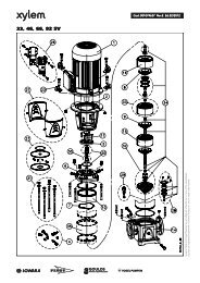
Installation, Operation and Maintenance InstructionModel <strong>LSB</strong>Installation Manual - Single mech. seal with quench without shaft sleeve(Design code S4..2)1. Safety InstructionsEvery person, who is responsible for theinstallation, removal, operation, start-up andmaintenance of the shaft seal, must also haveread and understood the Installation, Operationand Maintenance Instruction of the particularpump and especially chapter 8.1 "Generalremarks" and chapter 8.2 "General", and followthe instructions under any circumstances!For pumps which are designed in conformitywith the Directive 94/9/EG (Atex95) forenvironment endangered to explosion, theadditional Operating Instruction for explosionprotection of the mech. seal must be noticed.The following descriptions are only valid commonly, asfar as they refer to the inner design of the mech. seal.For possible particularities refer to the data sheet ofthe mech. seal or instruction of the mech. sealmanufacturer.2. DescriptionThis shaft seal is a single mech. seal with installationdimensions acc. EN 12756 (DIN 24960) design "K",form "U". API plan 62 / ISO plan 09. The resistance ofthe materials in the mech. seal chamber (especially ofelastomeres) against the quench liquid has to benoticed.The quench chamber must be flown through by thequench liquid without pressure. For connection refer tothe following sectional drawing.The liquid of the quench must be selected insuch way that there can not occur anydangerous reactions with the handled fluid. Theliquid of the quench can be contaminated due tothe handled fluid, therefore the operator mustcare for an adequate disposal.Because of the patented Cyclone Seal Chamber noadditional flushing of the seal chamber is necessary.For description of materials and operational range ofthe mech. seals supplied please refer to the datasheet in the Operation Instruction resp. orderconfirmation.QI ... Quench suction (471Q)Q0 ... Quench discharge (471Q)<strong>LSB</strong> 100-<strong>english</strong> page 92 Revision 02Artikel Nr. <strong>771076129</strong> Ausgabe 01/2010
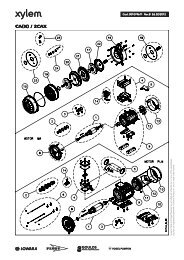
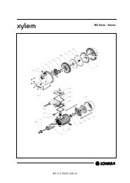
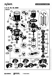
Installation, Operation and Maintenance InstructionModel <strong>LSB</strong>Index of parts:161 Casing cover210 Shaft230 Impeller412.23 O-ring412.32 O-ring435 Mech. seal471Q Quench cover502.31*) Wear ring527 a) Fixing ring542.31 Throttle bush560 b) Pin904.31 a) Grub screw904.32*) Grub screw927 Impeller nut*) optionala) not for all designsb) only for mech. seals with PTFE-O-ringsSubject to techn. alterations!Nominalsize ofmech. seal∅d 1 ∅d 7 l 1K A B ∅d L QI, Q033 33 48 42,5 7,5 50 1943 43 61 45 7,5 52,5 2853 53 73 47,5 10 57,5 381/4-18NPT3/8-18NPT3/8-18NPT3. Removal of mech. sealFor that purpose use the appropriate sectionaldrawing and the enclosed data sheet of the mech.seal. Remove and disassemble the pump acc. to theInstallation, Operation and MaintenanceInstructions including chapter 8.6. Remove fixing ring (527) (if existing) and rotatingpart of the mech. seal (433) from shaft (210). Refer to the enclosed data sheet of the mech.seal, if set screws are to be loosened at the mech.seal at first. Remove casing cover (161) together with quenchcover (471Q). Use hexagonal screws (901.42) asjack screws..Pull stationary part of the mech. seal (433) andthrottle bush (542.31) out of quench cover (471Q).Clean drilling for stationary seal ring (∅d 7 ) in thequench cover (471Q) and surface of the shaft(210).The reuse of mech. seals, which have alreadybeen used for a longer time, can lead to leakingat the seal faces after reinstallation. Thereforethe replacement of the mech. seal through anew one is recommended. The dismountedmechanical seal can be reconditioned by themanufacturer and serve as a replacementmech. seal.4. Installation of mech. sealFor that purpose use the appropriate sectionaldrawing and the enclosed data sheet of the mech.seal.It is only allowed to install mech. seals, whichhave a certificate of Conformity acc. theDirective 94/9/EG.On changing the mech. seal type resp. themech. seal manufacturer the data regardingmax. operating temperature of the pumpedmedium and temperature class must bechecked again.Pay attention to the utmost cleanness!Especially the seal faces must be clean, dry andundamaged. Don´t apply lubrication on the sealfaces of the mech. seal.If a lubricant is provided with the replacementmech. seal, you should use this.Use mineral grease or oil only, if you arecompletely sure that the elastomers of themech. seal are oil resistant. Use no silicone.Use only lubricants when you are sure thatthere can´t occur any dangerous reactionsbetween the pumpage and the lubricant.Make all required parts available, so thatassembly can be completed quickly. Thelubricants are only effective for a short time.After that the axial movability and, thus, theautomatic adjustment of the elastomeres is lost.Don´t push elastomers over sharp edges. Ifnecessary use mounting devices.Put throttle bush (542.31) into quench cover(471Q) carefully.Press the stationary part of the mech. seal in thequench cover (471Q). For this you can eventuallyuse a stamp with a soft surface. Unequal load canlead to cracking of the seal face.Don´t damage seal face!Pay attention that the stationary ring is in solidcontact with the quench cover. The seal face mustbe installed perpendicular to the shaft.If a pin (560) is existing, be careful that it fits intothe slot of the mech. sealing, without touching themech. seal.Insert casing cover (161) carefully, until it fitsaxially in the bearing frame lantern (344).Push the rotating unit of the mech. seal on theshaft (210).<strong>LSB</strong> 100-<strong>english</strong> page 93 Revision 02Artikel Nr. <strong>771076129</strong> Ausgabe 01/2010
- Page 1 and 2:
de VOGEL-SpiralgehäusepumpenBaurei
- Page 3 and 4:
Déclaration CE de conformité (val
- Page 5 and 6:
Einbau-, Betriebs- und Wartungsanle
- Page 7 and 8:
Einbau-, Betriebs- und Wartungsanle
- Page 9 and 10:
Einbau-, Betriebs- und Wartungsanle
- Page 11 and 12:
Einbau-, Betriebs- und Wartungsanle
- Page 13 and 14:
Einbau-, Betriebs- und Wartungsanle
- Page 15 and 16:
Einbau-, Betriebs- und Wartungsanle
- Page 17 and 18:
Einbau-, Betriebs- und Wartungsanle
- Page 19 and 20:
Einbau-, Betriebs- und Wartungsanle
- Page 21 and 22:
Einbau-, Betriebs- und Wartungsanle
- Page 23 and 24:
Einbau-, Betriebs- und Wartungsanle
- Page 25 and 26:
Einbau-, Betriebs- und Wartungsanle
- Page 27 and 28:
Einbau-, Betriebs- und Wartungsanle
- Page 29 and 30:
Einbau-, Betriebs- und Wartungsanle
- Page 31 and 32:
Einbau-, Betriebs- und Wartungsanle
- Page 33 and 34:
Einbau-, Betriebs- und Wartungsanle
- Page 35 and 36:
Einbau-, Betriebs- und Wartungsanle
- Page 37 and 38:
Einbau-, Betriebs- und Wartungsanle
- Page 39 and 40:
Instructions de montage, de service
- Page 41 and 42:
Instructions de montage, de service
- Page 43 and 44:
Instructions de montage, de service
- Page 45 and 46: Instructions de montage, de service
- Page 47 and 48: Instructions de montage, de service
- Page 49 and 50: Instructions de montage, de service
- Page 51 and 52: Instructions de montage, de service
- Page 53 and 54: Instructions de montage, de service
- Page 55 and 56: Instructions de montage, de service
- Page 57 and 58: Instructions de montage, de service
- Page 59 and 60: Instructions de montage, de service
- Page 61 and 62: Instructions de montage, de service
- Page 63 and 64: Instructions de montage, de service
- Page 65 and 66: Instructions de montage, de service
- Page 67 and 68: Instructions de montage, de service
- Page 69 and 70: Instructions de montage, de service
- Page 71 and 72: Instructions de montage, de service
- Page 73 and 74: Instructions de montage, de service
- Page 75 and 76: Installation, Operation and Mainten
- Page 77 and 78: Installation, Operation and Mainten
- Page 79 and 80: Installation, Operation and Mainten
- Page 81 and 82: Installation, Operation and Mainten
- Page 83 and 84: Installation, Operation and Mainten
- Page 85 and 86: Installation, Operation and Mainten
- Page 87 and 88: Installation, Operation and Mainten
- Page 89 and 90: Installation, Operation and Mainten
- Page 91 and 92: Installation, Operation and Mainten
- Page 93 and 94: Installation, Operation and Mainten
- Page 95: Installation, Operation and Mainten
- Page 99 and 100: Installation, Operation and Mainten
- Page 101 and 102: Installation, Operation and Mainten
- Page 103 and 104: Installation, Operation and Mainten
- Page 105 and 106: Installation, Operation and Mainten
- Page 107 and 108: Installation, Operation and Mainten