LSB german_french_english 771076129 - Water Solutions
LSB german_french_english 771076129 - Water Solutions
LSB german_french_english 771076129 - Water Solutions

Create successful ePaper yourself
Turn your PDF publications into a flip-book with our unique Google optimized e-Paper software.
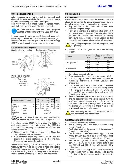
Installation, Operation and Maintenance InstructionModel <strong>LSB</strong>8.8 ReconditioningAfter disassembly all parts must be cleaned andchecked for wear carefully. Worn or damaged partsmust be replaced by new parts (spare parts).It is recommended in most cases to replace mech.seal, ball bearings and seals (flat seal, O-rings).All PTFE-sealing elements and graphitesealings are intended for being used only once.In most cases it make sense, if damaged absolutelynecessary, to renew the mech. seal and the bearingsDeposits on the impeller (230), in the volute casing(102V) or on the casing cover must be removed.8.8.1 Clearance at impellerSuction side of impeller Back vanes of impellerDrive side of impellerOnly with pump size100-65-315125-80-315125-100-315150-125-315Nominal diameter D (mm)606885100120135155175220Radialmin. 0,15 0,17 0,20 0,22 0,25newclearancemax. 0,19 0,22 0,24 0,27 0,30s (mm) worn 0,78 0,85 0,90 1,05 1,15Axial new 0,8 - 1,2clearancea (mm)worn max. 1,7When the wear limits has been reached orexceeded, the worn parts must be replaced.For volute casings (102V) with a wear ring (502.11)and cover casings (161) with a wear ring (502.31)there are the following possibilities to restore thecorrect clearance:a) Renew impeller (230) and wear ring. Then theoriginal measures are restored.b) A customized wear ring (bored to fit) can besupplied to avoid replacement of the impeller.Please contact factory for details.When volute casing (102V) or casing cover (161)without wear ring must be repaired, a wear ring can beinstalled to renew pump performance. Remachining ofthe volute casing and / or casing cover is required.Please contact the factory for details and assistance.8.9 Mounting8.9.1 GeneralRe-assemble the pumps using the reverse order ofsteps as completed for pump disassembly. Howeverthe following observations should be considered:Pay attention to the utmost cleanliness whenreassembling the pump. For tight tolerances e.g. between stub shaft (210)and motor shaft or impeller (230) and shaft (210),as well as thread, use suitable anti-gallingcompound (e.g. Molykote / Never-Seeze), so thatthe next mounting and dismounting will be easier.Anti-galling compound must be compatible withthe pumpage.Screws should be tightened, with the followingtorque:LocationCasing ScrewsAll other scresScrew torque in NmScrewLubricatedSizeDry threadsthreadsM12 35 50M16 105 150M20 210 305M10 35 50M12 60 90M16 150 220 Do not use excessive force. For mounting of stub shaft refer to chapter 8.9.2. For mounting of mech. seal refer to separate"Mounting Instruction of Shaft Sealing" andchapter 8.5. For impellers with back vanes the axial clearancebetween the back vanes and the casing cover(161) should be checked after mounting theimpeller (230) and tightening the impeller nut (922)(see chapter 8.8.1). After the mounting of the back pull out assembly,and its assembly into the volute casing, turn theshaft and control the free moving of the pump inthis way. The shaft sealings will cause slightlyresistance when turning, but there must not beany contact between metal parts.Before starting the pump do not forget to installand connect all security devices.8.9.2 Mounting of Stub Shaft Insert key in the motor stump. Put anti-galling compound onto the motor stump(see point 8.9.1). Push stub shaft up the motor shaft to measure A(see pict. 11 and chart). Drill countersink into motorshaft, appr. 2-3 mmdepth, through the radial bore in the motor shaft(see pict. 11), by useing a twistdrill with 90° tip. Remove cuttings out of the stud hole (e.g. withcompressed-air), screw in and make safe threadpins (904.41 and 904.42) (e.g. with Omnifit 100 Mor Loctite). Check smooth running of stub shaft opposite tomotor flange with a dial gauge. The pointerdeflection of the dial gauge must not exceed 0,1mm.<strong>LSB</strong> 100-<strong>english</strong> page 85 Revision 02Artikel Nr. <strong>771076129</strong> Ausgabe 01/2010