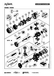
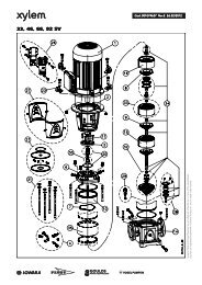
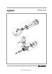
Installation, Operation and Maintenance InstructionModel <strong>LSB</strong>Using the jack screws provided (901.42), separatethe Back Pull Out Assembly from the casing.8.5 Removal of ImpellerNotice attached "Mounting Instruction for ShaftSealing".pic 8Pull up screw driver only so far as is absolutelynecessary to insert the guard plate into thewindow. If the guard plate doesn´t stick fast inthe window after installation:Dismantle guard plate once again, flatten it andinstall again.8.4 Removal of the Back Pull OutAssemblyThe back pull out assembly consists of all pump partsexcept the volute casing (102V). As the pumps areconstructed in block design, the volute casing (102V)can remain on the foundation and in the piping, if it´snot the volute casing itself, which must be repaired. Drain volute casing (102V) via drain plug (912.11). Loosen screws of existing sealing or flushingpipings. Loosen screws of support food (183) from thefoundation (not existing on all sizes). Hang the Back Pull Out Assembly onto a liftingdevice, so that it won´t sink down or press into thevolute casing during the dismounting. Examplesee picture 9 for lifting recommendations.If the impeller has back vanes check the axialclearance "a" between the impeller (230) andcasing cover (161) before you continue thedismounting. Refer to sect. 8.8.1.Loosen impeller nut with a sensitive hit on thewrench (right-hand thread). If necessary back upwith a pry bar in the cross boring of the stud shaft(in clamp area).Draw off the impeller (230) with two screw driversor pry bars (picture 10). Remove key (940.31).Be sure to locate pry bars under impeller vanesto prevent damage to the impeller.For further dismounting, and for installation, theBack Pull Out Assembly should be placed in avertical position. Prevent assembly from tipping!pic 108.6 Removal of Shaft SealingBefore you remove casing cover notice "MountingInstructions for Shaft Sealing".Unfasten hexagonal nut (902.32) (not available onall pump sizes) and take casing cover (161) out ofbearing bracket (344).pic 9Loosen hexagen head bolt (901.11) from thecasing.8.7 Removal of Stub ShaftLoosen screws (920.41) and pull motor with stubshaft (210) out of the motor lantern (341).Loosen radial stub shaft screwing (904.41 and904.42) (stud bolts) and deduct stub shaft (210)from motor shaft. For support (break loose) youcan insert a solid screw driver into the crossboring, press it against the front face of the motorand move both shafts against each other.<strong>LSB</strong> 100-<strong>english</strong> page 84 Revision 02Artikel Nr. <strong>771076129</strong> Ausgabe 01/2010
Installation, Operation and Maintenance InstructionModel <strong>LSB</strong>8.8 ReconditioningAfter disassembly all parts must be cleaned andchecked for wear carefully. Worn or damaged partsmust be replaced by new parts (spare parts).It is recommended in most cases to replace mech.seal, ball bearings and seals (flat seal, O-rings).All PTFE-sealing elements and graphitesealings are intended for being used only once.In most cases it make sense, if damaged absolutelynecessary, to renew the mech. seal and the bearingsDeposits on the impeller (230), in the volute casing(102V) or on the casing cover must be removed.8.8.1 Clearance at impellerSuction side of impeller Back vanes of impellerDrive side of impellerOnly with pump size100-65-315125-80-315125-100-315150-125-315Nominal diameter D (mm)606885100120135155175220Radialmin. 0,15 0,17 0,20 0,22 0,25newclearancemax. 0,19 0,22 0,24 0,27 0,30s (mm) worn 0,78 0,85 0,90 1,05 1,15Axial new 0,8 - 1,2clearancea (mm)worn max. 1,7When the wear limits has been reached orexceeded, the worn parts must be replaced.For volute casings (102V) with a wear ring (502.11)and cover casings (161) with a wear ring (502.31)there are the following possibilities to restore thecorrect clearance:a) Renew impeller (230) and wear ring. Then theoriginal measures are restored.b) A customized wear ring (bored to fit) can besupplied to avoid replacement of the impeller.Please contact factory for details.When volute casing (102V) or casing cover (161)without wear ring must be repaired, a wear ring can beinstalled to renew pump performance. Remachining ofthe volute casing and / or casing cover is required.Please contact the factory for details and assistance.8.9 Mounting8.9.1 GeneralRe-assemble the pumps using the reverse order ofsteps as completed for pump disassembly. Howeverthe following observations should be considered:Pay attention to the utmost cleanliness whenreassembling the pump. For tight tolerances e.g. between stub shaft (210)and motor shaft or impeller (230) and shaft (210),as well as thread, use suitable anti-gallingcompound (e.g. Molykote / Never-Seeze), so thatthe next mounting and dismounting will be easier.Anti-galling compound must be compatible withthe pumpage.Screws should be tightened, with the followingtorque:LocationCasing ScrewsAll other scresScrew torque in NmScrewLubricatedSizeDry threadsthreadsM12 35 50M16 105 150M20 210 305M10 35 50M12 60 90M16 150 220 Do not use excessive force. For mounting of stub shaft refer to chapter 8.9.2. For mounting of mech. seal refer to separate"Mounting Instruction of Shaft Sealing" andchapter 8.5. For impellers with back vanes the axial clearancebetween the back vanes and the casing cover(161) should be checked after mounting theimpeller (230) and tightening the impeller nut (922)(see chapter 8.8.1). After the mounting of the back pull out assembly,and its assembly into the volute casing, turn theshaft and control the free moving of the pump inthis way. The shaft sealings will cause slightlyresistance when turning, but there must not beany contact between metal parts.Before starting the pump do not forget to installand connect all security devices.8.9.2 Mounting of Stub Shaft Insert key in the motor stump. Put anti-galling compound onto the motor stump(see point 8.9.1). Push stub shaft up the motor shaft to measure A(see pict. 11 and chart). Drill countersink into motorshaft, appr. 2-3 mmdepth, through the radial bore in the motor shaft(see pict. 11), by useing a twistdrill with 90° tip. Remove cuttings out of the stud hole (e.g. withcompressed-air), screw in and make safe threadpins (904.41 and 904.42) (e.g. with Omnifit 100 Mor Loctite). Check smooth running of stub shaft opposite tomotor flange with a dial gauge. The pointerdeflection of the dial gauge must not exceed 0,1mm.<strong>LSB</strong> 100-<strong>english</strong> page 85 Revision 02Artikel Nr. <strong>771076129</strong> Ausgabe 01/2010
- Page 1 and 2:
de VOGEL-SpiralgehäusepumpenBaurei
- Page 3 and 4:
Déclaration CE de conformité (val
- Page 5 and 6:
Einbau-, Betriebs- und Wartungsanle
- Page 7 and 8:
Einbau-, Betriebs- und Wartungsanle
- Page 9 and 10:
Einbau-, Betriebs- und Wartungsanle
- Page 11 and 12:
Einbau-, Betriebs- und Wartungsanle
- Page 13 and 14:
Einbau-, Betriebs- und Wartungsanle
- Page 15 and 16:
Einbau-, Betriebs- und Wartungsanle
- Page 17 and 18:
Einbau-, Betriebs- und Wartungsanle
- Page 19 and 20:
Einbau-, Betriebs- und Wartungsanle
- Page 21 and 22:
Einbau-, Betriebs- und Wartungsanle
- Page 23 and 24:
Einbau-, Betriebs- und Wartungsanle
- Page 25 and 26:
Einbau-, Betriebs- und Wartungsanle
- Page 27 and 28:
Einbau-, Betriebs- und Wartungsanle
- Page 29 and 30:
Einbau-, Betriebs- und Wartungsanle
- Page 31 and 32:
Einbau-, Betriebs- und Wartungsanle
- Page 33 and 34:
Einbau-, Betriebs- und Wartungsanle
- Page 35 and 36:
Einbau-, Betriebs- und Wartungsanle
- Page 37 and 38: Einbau-, Betriebs- und Wartungsanle
- Page 39 and 40: Instructions de montage, de service
- Page 41 and 42: Instructions de montage, de service
- Page 43 and 44: Instructions de montage, de service
- Page 45 and 46: Instructions de montage, de service
- Page 47 and 48: Instructions de montage, de service
- Page 49 and 50: Instructions de montage, de service
- Page 51 and 52: Instructions de montage, de service
- Page 53 and 54: Instructions de montage, de service
- Page 55 and 56: Instructions de montage, de service
- Page 57 and 58: Instructions de montage, de service
- Page 59 and 60: Instructions de montage, de service
- Page 61 and 62: Instructions de montage, de service
- Page 63 and 64: Instructions de montage, de service
- Page 65 and 66: Instructions de montage, de service
- Page 67 and 68: Instructions de montage, de service
- Page 69 and 70: Instructions de montage, de service
- Page 71 and 72: Instructions de montage, de service
- Page 73 and 74: Instructions de montage, de service
- Page 75 and 76: Installation, Operation and Mainten
- Page 77 and 78: Installation, Operation and Mainten
- Page 79 and 80: Installation, Operation and Mainten
- Page 81 and 82: Installation, Operation and Mainten
- Page 83 and 84: Installation, Operation and Mainten
- Page 85 and 86: Installation, Operation and Mainten
- Page 87: Installation, Operation and Mainten
- Page 91 and 92: Installation, Operation and Mainten
- Page 93 and 94: Installation, Operation and Mainten
- Page 95 and 96: Installation, Operation and Mainten
- Page 97 and 98: Installation, Operation and Mainten
- Page 99 and 100: Installation, Operation and Mainten
- Page 101 and 102: Installation, Operation and Mainten
- Page 103 and 104: Installation, Operation and Mainten
- Page 105 and 106: Installation, Operation and Mainten
- Page 107 and 108: Installation, Operation and Mainten