Bruciatori di gas ad aria soffiata Gebläse ... - Riello Burners
Bruciatori di gas ad aria soffiata Gebläse ... - Riello Burners
Bruciatori di gas ad aria soffiata Gebläse ... - Riello Burners
- No tags were found...

You also want an ePaper? Increase the reach of your titles
YUMPU automatically turns print PDFs into web optimized ePapers that Google loves.
DATI TECNICII10MODELLO RS 70/M RS 100/M RS 130/MTIPO 828 T1 829 T1 830 T1POTENZA (1) MAX. kW 465 - 814698 - 1163930 - 1512Mcal/h 400 - 700600 - 1000800 - 1300MIN. kW 135150160Mcal/h116129138COMBUSTIBILEGAS NATURALE: G20 - G21 - G22 - G23 - G25G20 G25 G20 G25 G20 G25- Potere calorifico inferiore kWh/Nm 38,6 10 8,6 10 8,6Mcal/Nm 3 8,6 7,4 8,6 7,4 8,6 7,4- Densità assoluta kg/Nm 3 0,71 0,78 0,71 0,78 0,71 0,78- Portata massima Nm 3 /h 81 94 116 135 151 175- Pressione alla portata massima (2) mbar 10,3 15,2 9,3 13,7 8,6 12,7FUNZIONAMENTO• Intermittente (min. 1 arresto in 24 ore).Questi bruciatori sono <strong>ad</strong>atti anche al funzionamento continuo se vengonoequippaggiati con l’apparecchiatura Lan<strong>di</strong>s LGK 16.333 A27 (intercambiabilecon l’apparecchiatura Lan<strong>di</strong>s LFL 1.333 del bruciatore).• Due sta<strong>di</strong> progressivi o modulante con kit (ve<strong>di</strong> ACCESSORI).IMPIEGO STANDARDCaldaie: <strong>ad</strong> acqua, a vapore, <strong>ad</strong> olio <strong>di</strong>atermicoTEMPERATURA AMBIENTE °C 0 - 40TEMPERATURA ARIA COMBURENTE °C max 60ALIMENTAZIONE ELETTRICAVHz230 - 400 con neutro ~ +/-10%50 - trifaseMOTORE ELETTRICOrpmWVA28001100220/240 - 380/4154,8 - 2,828001500220/240 - 380/4155,9 - 3,428002200220/240 - 380/4158,8 - 5,1TRASFORMATORE D’ACCENSIONEV1 - V2I1 - I2230 V - 1 x 8 kV1 A - 20 mAPOTENZA ELETTRICA ASSORBITA W max 1400 1800 2600GRADO DI PROTEZIONE IP 44CONFORMITÀ DIRETTIVE CEE 90/396 - 89/336 - 2004/108 - 73/23 - 2006/95RUMOROSITÀ (3) dBA 75 77 78,5OMOLOGAZIONE CE 0085AQ0708(1) Con<strong>di</strong>zioni <strong>di</strong> riferimento: Temperatura ambiente 20°C - Pressione barometrica 1000 mbar - Altitu<strong>di</strong>ne 100 m s.l.m.(2) Pressione alla presa 16)(A)p.8 con pressione zero in camera <strong>di</strong> combustione, con la ghiera del <strong>gas</strong> 2)(B)p.16 aperta ed alla potenza massima del bruciatore.(3) Pressione sonora misurata nel laboratorio combustione del costruttore, con bruciatore funzionante su caldaia <strong>di</strong> prova, alla potenza massima.VERSIONI COSTRUTTIVE:BRUCIATORE RS 70/M RS 100/M RS 130/MLunghezza boccaglio mm 250 385 250 385 280 415ACCESSORI (su richiesta):• KIT TESTA LUNGABRUCIATORE RS 70/M RS 100/M RS 130/MCo<strong>di</strong>ce 3010117 3010118 3010119PAESEIT-AT-GR-DK-FI-SEES-GB-IE-PTNLFRDEBELU• KIT PER FUNZIONAMENTO A GPL: il kit consente ai bruciatori RS 70-100-130/M <strong>di</strong> bruciare GPL.BRUCIATORE RS 70/M RS 100/M RS 130/MPotenza kW 242 ÷ 814 349 ÷ 1163 466 ÷ 1512Co<strong>di</strong>ce 3010097 3010098 3010099 3010100 3010101 3010102• KIT RIDUZIONE VIBRAZIONIBRUCIATORE RS 70/M RS 100/M RS 130/MPotenza kW 192 ÷ 814 232 ÷ 1163 185 ÷ 1461Co<strong>di</strong>ce 3010201 3010202 3010373 3010374• KIT REGOLATORE DI POTENZA PER FUNZIONAMENTO MODULANTE: con il funzionamento modulante il bruciatore <strong>ad</strong>egua continuamentela potenza alla richiesta <strong>di</strong> calore assicurando grande stabilità al parametro controllato: temperatura o pressione. I componenti da or<strong>di</strong>naresono due: • il regolatore <strong>di</strong> potenza da installare sul bruciatore; • la sonda da installare sul generatore <strong>di</strong> calore.PARAMETRO DA CONTROLLARE SONDA REGOLATORE DI POTENZACampo <strong>di</strong> regolazione Tipo Co<strong>di</strong>ce Tipo Co<strong>di</strong>ceTemperatura - 100...+ 500°C PT 100 30101100...2,5 barSonda con uscita 3010213 RWF40 3010212Pressione0...16 bar4...20 mA 3010214• RAMPE GAS SECONDO NORMA EN 676 (complete <strong>di</strong> valvole, regolatore <strong>di</strong> pressione e filtro): vedere a pagina 18.Importante: L’installatore è responsabile per l’eventuale aggiunta <strong>di</strong> organi <strong>di</strong> sicurezza non previsti in questo manuale.CATEGORIAII 2H3B/PII 2H3PII 2L3B/PII 2Er3PII 2ELL3B/PI 2E(R)B, I 3PII 2E3B/P4
TECHNISCHE ANGABEND10MODELL RS 70/M RS 100/M RS 130/MTYP 828 T1 829 T1 830 T1LEISTUNG (1) 2° Stufe kW 465 - 814698 - 1163930 - 1512Mcal/h 400 - 700600 - 1000800 - 1300min. 1° Stufe kW 135150160Mcal/h116129138BRENNSTOFFERDGAS: G20 - G21 - G22 - G23 - G25- Bezug G20 G25 G20 G25 G20 G25- Unterer Heizwert Hu kWh/Nm 38,6 10 8,6 10 8,6Mcal/Nm 3 8,6 7,4 8,6 7,4 8,6 7,4- Rein<strong>di</strong>chte kg/Nm 3 0,71 0,78 0,71 0,78 0,71 0,78- Höchstdruchsatz Nm 3 /h 81 94 116 135 151 175- Druck bei Höchstleistung (2) mbar 10,3 15,2 9,3 13,7 8,6 12,7BETRIEB• Intermittierend (min. 1 Abschaltung in 24 Std).Wenn <strong>di</strong>eser Brenner mit dem Gasfeuerungsautomaten Lan<strong>di</strong>s & GyrLGK 16.333 A27 ausgestattet ist, ist er auch für den Dauerbetrieb geeignet.Die elektrische Verdrahtung des Brenners bleibt unverändert.• Gleitend zweistufig (modulierend mit Kit).STANDARDEINSATZHeizkessel: mit Wasser, Dampf, <strong>di</strong>athermischem ÖlRAUMTEMPERATUR °C 0 - 40TEMPERATUR VERBRENNUNGSLUFT °C max 60ELEKTRISCHE SPANNUNGVHz230 - 400 mit Nulleiter ~ +/-10%50 - dreiphasingELEKTROMOTORrpmWVA28001100220/240 - 380/4154,8 - 2,828001500220/240 - 380/4155,9 - 3,428002200220/240 - 380/4158,8 - 5,1ZÜNDTRASNFORMATORV1 - V2I1 - I2230 V - 1 x 8 kV1 A - 20 mAAUFGENOMMENE STROMLEISTUNG W max 1400 1800 2600SCHUTZART IP 44CE-NORMGERECHT 90/396 - 89/336 - 2004/108 - 73/23 - 2006/95SHALLDRUCKPEGEL (3) dBA 75 77 78,5ZULASSUNGEN CE 0085AQ0708(1) Bezugsbe<strong>di</strong>ngungen: Raumtemperatur 20°C - Barometrischer Druck 1000 mbar - Höhe 100 m ü.d.M.(2) Druck am Anschluß 16)(A)S.8 bei druckloser Brennkammer, geöffneter Gasscheibe 2)(B)S.16 und bei Höchstleistung des Brenners(3) Schalldruck, im Brennprüflabor des Herstellers mit Brenner auf Prüfkessel bei Höchstleistung.BAUVARIANTEN:BRENNER RS 70/M RS 100/M RS 130/MFlammrohr Länge mm 250 385 250 385 280 415ZUBEHÖRTEILE (auf Wunsch):• KIT FLAMMKOPFVERLÄNGERUNGBRENNER RS 70/M RS 100/M RS 130/MCode 3010117 3010118 3010119LANDIT-AT-GR-DK-FI-SEES-GB-IE-PTNLFRDEBELU• KIT FÜR FLÜSSIGGAS-BETRIEB: Der Kit erlaubt den Brennern RS 70-100-130/M Flüssig<strong>gas</strong> zu brennen.BRENNER RS 70/M RS 100/M RS 130/MLeistung kW 242 ÷ 814 349 ÷ 1163 466 ÷ 1512Code 3010097 3010098 3010099 3010100 3010101 3010102• KIT ZUR REDUZIERUNG DER VIBRATIONENBRENNER RS 70/M RS 100/M RS 130/MLeistung kW 192 ÷ 814 232 ÷ 1163 185 ÷ 1461Code 3010201 3010202 3010373 3010374• KIT FÜR DIE LEISTUNGSREGELUNG BEI MODULIERENDEM BETRIEB: Bei modulierendem Betrieb passt der Brenner <strong>di</strong>e Leistung stufenlosdem Wärmebedarf an und stellt konstante Temperatur- oder Druckwerte sicher. Folgende Zubehörteile müssen bestellt werden:• der Leistungsregler (an den Brenner einzubauen); • der Fühler (an den Wärmeerzeuger einzubauen).WERT ZU ÜBERWACHEN FÜHLER LEISTUNGSREGLERRegelbereich Typ Code Typ CodeTemperatur - 100...+ 500°C PT 100 30101100...2,5 barFühler mit Ausgang 3010213 RWF40 3010212Druck0...16 bar4...20 mA 3010214• GASARMATUREN GEMÄß NORM EN 676 (mit Ventilen, Druckregler und Filter): siehe Seite 18.KATEGORIEII 2H3B/PII 2H3PII 2L3B/PII 2Er3PII 2ELL3B/PI 2E(R)B, I 3PII 2E3B/PWichtiger Hinweis: Der Installateur haftet für den eventuellen Zusatz von Sicherheitsteilen, <strong>di</strong>e nicht in <strong>di</strong>eser Betriebsanleitung vorgesehen sind.5
TECHNICAL DATA10MODEL RS 70/M RS 100/M RS 130/MTYPE 828 T1 829 T1 830 T1OUTPUT (1) MAX. kW 465 - 814698 - 1163930 - 1512Mcal/h 400 - 700600 - 1000800 - 1300MIN. kW 135150160Mcal/h116129138FUELNATURAL GAS: G20 - G21 - G22 - G23 - G25G20 G25 G20 G25 G20 G25- Net calorific value kWh/Nm 38,6 10 8,6 10 8,6Mcal/Nm 3 8,6 7,4 8,6 7,4 8,6 7,4- Absolute density kg/Nm 3 0,71 0,78 0,71 0,78 0,71 0,78- Max. delivery Nm 3 /h 81 94 116 135 151 175- Pressure at max. delivery (2) mbar 10,3 15,2 9,3 13,7 8,6 12,7OPERATION• On-Off (1 stop min each 24 hours).This burner is also fitted for the continuos operation, if it is equippedwith the control box LANDIS type LGK 16.333 A27 (interchangeablewith the burner control box Lan<strong>di</strong>s LFL 1.333).• Progressive two-stage or modulating by kit (see ACCESSOIRES).STANDARD APPLICATIONSBoilers: water, steam, <strong>di</strong>athermic oilAMBIENT TEMPERATUR °C 0 - 40COMBUSTION AIR TEMPERATURE °C max 60ELECTRICAL SUPPLYVHz230 - 400 with neutral ~ +/-10%50 - three-phaseELECTRIC MOTORrpmWVA28001100220/240 - 380/4154,8 - 2,828001500220/240 - 380/4155,9 - 3,428002200220/240 - 380/4158,8 - 5,1IGNITION TRANSFORMERV1 - V2I1 - I2230 V - 1 x 8 kV1 A - 20 mAELECTRICAL POWER CONSUMPTION W max 1400 1800 2600ELECTRICAL PROTECTION IP 44IN CONFORMITY WITH EEC DIRECTIVES 90/396 - 89/336 - 2004/108 - 73/23 - 2006/95NOISE LEVELS (3) dBA 75 77 78,5APPROVAL CE 0085AQ0708(1) Reference con<strong>di</strong>tions: Ambient temperature 20°C - Barometric pressure 1000 mbar - Altitude 100 m s.l.m.(2) Pressure at test point 16)(A)p.8, with zero pressure in the combustion chambre, with open <strong>gas</strong> ring 2)(B)p.16 an maximum burner output(2) Sound pressure measured in manufacturer’s combustion laboratory, with burner operating on test boiler and at maximum rated output.VARIANTS:BURNER RS 70/M RS 100/M RS 130/MBlast tube lenght mm 250 385 250 385 280 415ACCESSORIES (optional):• KIT LONG HEADBURNER RS 70/M RS 100/M RS 130/MCode 3010117 3010118 3010119COUNTRYIT-AT-GR-DK-FI-SEES-GB-IE-PTNLFRDEBELU• KIT FOR LPG OPERATION: The kit allows the RS 70-100-130/M burners to operate on LPG.BURNER RS 70/M RS 100/M RS 130/MOutput kW 242 ÷ 814 349 ÷ 1163 466 ÷ 1512Code 3010097 3010098 3010099 3010100 3010101 3010102• VIBRATION REDUCTION KITBURNER RS 70/M RS 100/M RS 130/MOutput kW 192 ÷ 814 232 ÷ 1163 185 ÷ 1461Code 3010201 3010202 3010373 3010374• OUTPUT POWER REGULATOR KIT: Under modulating operation, the burner automatically <strong>ad</strong>apts to one of an infinite number of firing ratesbetween the low and high flame output position, thus ensuring stable operating con<strong>di</strong>tions in terms of temperature or pressure. Two componentsshould be ordered: • Power regulator to install to the burner; • probe to install to the boiler.PARAMETER TO BE CHECKED PROBE POWER REGULATORRange Type Code Type CodeTemperature - 100...+ 500°C PT 100 30101100...2,5 barOutput probe 3010213 RWF40 3010212Pressure0...16 bar4...20 mA 3010214• GAS TRAIN ACCORDING TO REGULATION EN 676 (with valves, pressure governor and filter): see page 18.Important: The installer is responsible for the <strong>ad</strong><strong>di</strong>tion of any safety device not forseen in the present manual.CATEGORYII 2H3B/PII 2H3PII 2L3B/PII 2Er3PII 2ELL3B/PI 2E(R)B, I 3PII 2E3B/PGB6
DONNEES TECHNIQUES10MODELE RS 70/M RS 100/M RS 130/MTYPE 828 T1 829 T1 830 T1PUISSANCE (1) MAX. kW 465 - 814698 - 1163930 - 1512Mcal/h 400 - 700600 - 1000800 - 1300MIN. kW 135150160Mcal/h116129138COMBUSTIBLEGAZ NATUREL: G20 - G21 - G22 - G23 - G25G20 G25 G20 G25 G20 G25- Pouvoir calorifique inférieur kWh/Nm 38,6 10 8,6 10 8,6Mcal/Nm 3 8,6 7,4 8,6 7,4 8,6 7,4- Densité absolue kg/Nm 3 0,71 0,78 0,71 0,78 0,71 0,78- Débit maximum Nm 3 /h 81 94 116 135 151 175- Pression au débit max. (2) mbar 10,3 15,2 9,3 13,7 8,6 12,7FONCTIONNEMENT• Intermittent (1 arrêt min en 24 heures).Ce brûleurs est appropriés aussi pour le service permanent, s’ilest équipés avec le boîtier LANDIS type LGK 16.333 A 27(interchangeable avec le boîtier, LANDIS type LFL 1.333, du brûleur).• Deux allure progressives ou modulant avec kit (voir ACCESSOIRES).EMPLOI STANDARDChau<strong>di</strong>ères à eau, à vapeur, à huile <strong>di</strong>athermiqueTEMPERATURE AMBIANTE °C 0 - 40TEMPERATURE AIR COMBURANT °C max 60ALIMENTATION ELECTRIQUEVHz230 - 400 avec neutre ~ +/-10%50 - triphaséeMOTEUR ELECTRIQUErpmWVA28001100220/240 - 380/4154,8 - 2,828001500220/240 - 380/4155,9 - 3,428002200220/240 - 380/4158,8 - 5,1TRANSFORMATEUR D’ALLUMAGEV1 - V2I1 - I2230 V - 1 x 8 kV1 A - 20 mAPUISSANCE ELECTRIQUE ABSORBEE W max 1400 1800 2600DEGRE DE PROTECTION IP 44CONFORMÉMENT AUX DIRECTIVES CEE 90/396 - 89/336 - 2004/108 - 73/23 - 2006/95NIVEAU DE BRUIT (3) dBA 75 77 78,5HOMOLOGATION CE 0085AQ0708(1) Con<strong>di</strong>tions de référence: Température ambiante 20°C - Pression barométrique 1000 mbar - Altitude 100 m au-dessus du niveau de la mer.(2) Pression à la prise 16)(A)p.8, avec une pression nulle dans la chambre de combustion, avec la bague du gaz 2)(B)p.16 ouverte et à la puissancemaximum du brûleur.(3) Pression acoustique mesurée dans le laboratoire combustion du constructeur, le brûleur fonctionnant sur une chau<strong>di</strong>ère d’essai à la puissance maximum.MODELES DISPONIBLES:BRULEUR RS 70/M RS 100/M RS 130/MLonguer buse mm 250 385 250 385 280 415ACCESSOIRES (sur demande):• KIT TETE LONGUEBRULEUR RS 70/M RS 100/M RS 130/MCode 3010117 3010118 3010119PAYSIT-AT-GR-DK-FI-SEES-GB-IE-PTNLFRDEBELU• KIT POUR FONCTIONNEMENT AU GPL: Le kit permet aux brûleurs RS 70-100-130/M de fonctionner au GPL.BRULEUR RS 70/M RS 100/M RS 130/MPuissance kW 242 ÷ 814 349 ÷ 1163 466 ÷ 1512Code 3010097 3010098 3010099 3010100 3010101 3010102• KIT RÉDUCTION DES VIBRATIONSBRULEUR RS 70/M RS 100/M RS 130/MPuissance kW 192 ÷ 814 232 ÷ 1163 185 ÷ 1461Code 3010201 3010202 3010373 3010374• KIT REGULATEUR DE PUISSANCE POUR FONCTIONNEMENT MODULANT: En fonctionnement modulant, le brûleur <strong>ad</strong>apte continuellementla puissance à la demande de chaleur assurant une grande stabilité au paramètre contrôlé: température ou pression. Il faut commander 2composants: • Le régulateur de puissance à installer sur le brûleur; • la sonde à installer sur le générateur de chaleur.PARAMETRE A CONTROLER SONDE REGULATEUR DE PUISSANCEPlage de régulation Type Code Type CodeTempérature - 100...+ 500°C PT 100 30101100...2,5 barSonde avec sortie 3010213 RWF40 3010212Pression0...16 bar4...20 mA 3010214• RAMPES GAZ SELON LA NORME EN 676 (avec vannes, regulateur de pression et filtre): voir p. 18.Attention: Si l’installateur ajoute des organes de sécurité non prévus dans ce manuel, il en assume la responsabilité.CATEGORIEII 2H3B/PII 2H3PII 2L3B/PII 2Er3PII 2ELL3B/PI 2E(R)B, I 3PII 2E3B/PF7
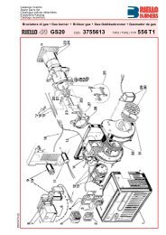
(A)mm A (1) B C kgRS 70/M 1190-1325 740 692 70RS 100/M 1190-1325 740 692 73RS 130/M 1190-1325 740 692 76(B)D881D36DESCRIZIONE BRUCIATORE (A)1 Testa <strong>di</strong> combustione2 Elettrodo <strong>di</strong> accensione3 Vite per regolazione testa <strong>di</strong> combustione4 Pressostato <strong>gas</strong> <strong>di</strong> massima5 Servomotore, comanda la farfalla del <strong>gas</strong> e,tramite una camma a profilo v<strong>aria</strong>bile, la serrand<strong>ad</strong>ell’<strong>aria</strong>.Durante la sosta del bruciatore la serrand<strong>ad</strong>ell’<strong>aria</strong> è completamente chiusa per ridurreal minimo le <strong>di</strong>spersioni termiche della caldai<strong>ad</strong>ovute al tiraggio del camino cherichiama l’<strong>aria</strong> dalla bocca <strong>di</strong> aspirazione delventilatore.6 Spina-presa sul cavo della sonda <strong>di</strong> ionizzazione7 Prolunghe per guide 15)8 Contattore motore e relè termico con pulsante<strong>di</strong> sblocco9 Un interruttore per:funzionamento automatico-manuale-spentoUn pulsante per:aumento - <strong>di</strong>minuzione potenza10 Morsettiera per il collegamento elettrico11 Passacavi per i collegamenti elettrici a cur<strong>ad</strong>ell’installatore12 Apparecchiatura elettrica con avvisatoreluminoso <strong>di</strong> blocco e pulsante <strong>di</strong> sblocco13 Visore fiamma14 Pressostato <strong>aria</strong> (tipo <strong>di</strong>fferenziale)15 Guide per apertura bruciatore ed ispezionealla testa <strong>di</strong> combustione16 Presa <strong>di</strong> pressione <strong>gas</strong> e vite fissa testa17 Presa <strong>di</strong> pressione <strong>aria</strong>18 Sonda per il controllo presenza fiamma19 Serranda <strong>aria</strong>20 Ingresso <strong>aria</strong> nel ventilatore21 Viti per il fissaggio ventilatore al manicotto22 Condotto arrivo <strong>gas</strong>23 Valvola farfalla <strong>gas</strong>24 Flangia per il fissaggio alla caldaia25 Disco <strong>di</strong> stabilità fiamma26 Staffa per l’applicazione del regolatore <strong>di</strong>potenza RWF40Vi sono due possibilità <strong>di</strong> blocco del bruciatore:• BLOCCO APPARECCHIATURA:l’accensione del pulsante dell’apparecchiatura12)(A) avverte che il bruciatore è in blocco.Per sbloccare premere il pulsante.• BLOCCO MOTORE:alimentazione elettrica a due fasi, per sbloccarepremere il pulsante del relè termico 8)(A).IMBALLO - PESO (B) - misure in<strong>di</strong>cative• L’imballo del bruciatore appoggia su unapedana in legno particolarmente <strong>ad</strong>atta ai carrellielevatori. Le <strong>di</strong>mensioni <strong>di</strong> ingombrodell'imballo sono riportate nella tabella (B).• Il peso del bruciatore completo <strong>di</strong> imballo èin<strong>di</strong>cato nella tabella (B).D731(C)INGOMBRO (C) - misure in<strong>di</strong>cativeL'ingombro del bruciatore è riportato in fig. (C).Tener presente che per ispezionare la testa <strong>di</strong>combustione il bruciatore deve essere apertoarretrandone la parte posteriore sulle guide.L'ingombro del bruciatore aperto è in<strong>di</strong>cato dallaquota I.mm A B C D E F G H I (1) L M N ORS 70/M 511 296 215 555 840 250-385 179 430 1161-1296 214 134 221 2”RS 100/M 527 312 215 555 840 250-385 179 430 1161-1296 214 134 221 2”RS 130/M 553 338 215 555 840 280-415 189 430 1161-1296 214 134 221 2”(1) Boccaglio: corto-lungo / Flammenrohr: kurz-lang / Blast tube: short-long / Buse: courte-longueCORREDO1 - Flangia per rampa <strong>gas</strong>1 - Guarnizione per flangia4 - Viti per fissare la flangia M 8 x 251 - Schermo termico2 - Prolunghe 7)(A) per guide 15)(A)(modelli con boccaglio 385 - 415 mm)4 - Viti per fissare la flangia del bruciatore allacaldaia: M 12 x 351 - Istruzione1 - Catalogo ricambi8
BRENNERBESCHREIBUNG (A)1 Flammkopf2 Zündelektrode3 Einstellschraube des Flammkopfes4 Gas-Höchstdruckwächter5 Stellantrieb zur Steuerung der Gasdrosselund, über einen Nocken mit v<strong>aria</strong>blem Profil,der Luftklappe.Bei Brennerstillstand ist <strong>di</strong>e Luftklappe vollstän<strong>di</strong>ggeschlossen, um <strong>di</strong>e Wärmeverlustedes Kessels durch den Kaminzug mit Luftnachführungvon der Saugöffnung desGebläses zu vermindern.6 Steckanschluß am Kabel der Ionisationssonde7 Verlängerungen zu Gleitschienen 15)8 Motorschütz und Überstromauslöser mit Entriegelungsschalter9 Ein Schalter für:Automatischer Betrieb-Manueller Betrieb-AusEin Druckknopf für:Leistungserhöhung - Leistungabminderung10 Anschlußklemmenbrett11 Kabeldurchgänge für <strong>di</strong>e Elektroanschlüssevom Installateur auszuführen12 Steuergerät mit Kontrollampe für Störabschaltungund Entriegelungsschalter13 Sichtfenster14 Luftdruckwächter (Differentialtyp)15 Gleitschienen zur Öffnung des Brenners undfür <strong>di</strong>e Kontrolle des Flammkopfs16 Gasdruckentnahmestelle und Befestigungsschraubedes Flammkopfes17 Luftdruckentnahmestelle18 Flammenfühler19 Luftklappe20 Lufteinlaß zum Gebläse21 Befestigungsschrauben des Gebläses an derGasanschluß-Muffe22 Gaszuleitung23 Gasdrossel24 Befestigungsflansch am Kessel25 Stauscheibe26 Tragbügel zum Einbau des LeistungsreglersRWF40Die Störabschaltungen des Brenners könnenzweierlei Art sein:• STÖRABSCHALTUNG DES GERÄTES:das Aufleuchten des Druckknopfes des Gerätes,12)(A) weist auf eine Störabschaltungdes Brenners hin.Zur Entriegelung den Druckknopf drücken.• STÖRABSCHALTUNG MOTOR:Zweiphasen-Stromversongung: Entriegelungdurch Drücken auf den Druckknopf des Überstromauslösers,Pos 8)(A).VERPACKUNG - GEWICHT (B) - Richtwerte• Der Brenner steht auf einem besonders für<strong>di</strong>e Handhabung mit Hubwagen geeignetemHolzrahmen. Die Außenabmessungen derVerpackung sind in Tabelle (B) aufgeführt.• Das Gesamtgewicht des Brenners einschließlichVerpackung wird aus Tabelle (B) ersichtlich.ABMESSUNGEN (C) - RichtwerteDie Brennerabmessungen sind in der Abb. (C)angeführt.Beachten Sie, daß der Brenner für <strong>di</strong>e Flammkopfinspektiongeöffnet werden muß, indemsein rückwärtiger Teil auf den Gleitschienennach hinten geschoben wird.Die Abmessungen des ausgeschwenkten Brennerssind unter I aufgeführt.AUSSTATTUNG1 - Flansch für Gasarmaturen1 - Dichtung für Flansch4 - Schrauben für <strong>di</strong>e Befestigung des M 8 x 25Flansches1 - Wärmeschild2 - Verlängerungen 7)(A) zu Gleitschienen 15)(A)(Modelle mit Flammrohr 385 - 415 mm)4 - Schrauben für <strong>di</strong>e Befestigung des Brennerflanschsam Kessel: M12 x 351 - Anleitung1 - Ersatzteile KatalogBURNER DESCRIPTION (A)1 Combustion he<strong>ad</strong>2 Ignition electrode3 Screw for combustion he<strong>ad</strong> <strong>ad</strong>justment4 Max. <strong>gas</strong> pressure switch5 Servomotor controlling the <strong>gas</strong> butterflyvalve and the air gate valve (by means of av<strong>aria</strong>ble profile cam mechanism).When the burner is stopped the air gatevalve will be completely closed to reduceheat loss due to the flue draught, whichtends to draws air from the fan air inlet.6 Plug-socket on ionisation proble cable7 Extensions for slide bars 15)8 Motor contactor and thermal cut-out withreset button9 Power switch for <strong>di</strong>fferent operations:automatic - manual - offButton for:power increase - power reduction10 Terminal strip for electrical connection11 Fairle<strong>ad</strong>s for electrical connections byinstaller12 Control box with lock-out pilot light and lockoutreset button13 Flame inspection window14 Minimum air pressure switch(<strong>di</strong>fferential operating type)15 Slide bars for opening the burner an<strong>di</strong>nspecting the combustion he<strong>ad</strong>16 Gas pressure test point and he<strong>ad</strong> fixingscrew17 Air pressure test point18 Flame sensor probe19 Air gate valve20 Air inlet to fan21 Screws securing fan to sleeve22 Gas input pipework23 Gas butterfly valve24 Boiler mounting flange25 Flame stability <strong>di</strong>sk26 Bracket for mounting the power regulatorRWF40Two types of burner failure may occur:• CONTROL BOX LOCK-OUT:if the control box 12)(A) pushbutton lights up,it in<strong>di</strong>cates that the burner is in lock-out.To reset, press the pushbutton.• MOTOR TRIP:two-phase electricity supply; release bypressing the pushbutton on thermal cutout8)(A).PACKAGING - WEIGHT (B) - Approximatemeasurements• The burners stands on a wooden base whichcan be lifted by fork-lifts.Outer <strong>di</strong>mensions of packaging are in<strong>di</strong>cate<strong>di</strong>n (B).• The weight of the burner complete with packagingis in<strong>di</strong>cated in Table (B).MAX. DIMENSIONS (C) - Approximate measurementsThe maximum <strong>di</strong>mensions of the burner aregiven in (C).Bear in mind that inspection of the combustionhe<strong>ad</strong> requires the burner to be opened by withdrawingthe rear part on the slide bars.The maximum <strong>di</strong>mension of the burner, whenopen is give by measurement I.STANDARD EQUIPMENT1 - Gas train flange1 - Flange <strong>gas</strong>ket4 - Flange fixing screws M 8 x 251 - Thermal insulation screen2 - Extensions 7)(A) for slide bars 15)(A)(for models with 385 - 415 mm blast tube)4 - Screws to secure the burner flange to theboiler: M 12 x 351 - Instruction booklet1 - Spare parts listDESCRIPTION BRULEUR (A)1 Tête de combustion2 Electrode d'allumage3 Vis pour réglage tête de combustion4 Pressostat gaz seuil maximum5 Servomoteur de commande de la vannepapillon du gaz et, par came à profil v<strong>aria</strong>ble,du volet d'air.Lors de l'arrêt du brûleur, le volet d'air esttotalement fermé pour réduire au minimumles <strong>di</strong>spersions de chaleur de la chau<strong>di</strong>èredues au tirage de la cheminée qui aspire l'airpar la bouche d'aspiration du ventilateur.6 Fiche prise sur câble sonde d’ionisation7 Rallonges pour guides 15)8 Contacteur moteur et relais thermique avecbouton de déblocage9 Un interrupteur pour le fonctionnement:automatique - manuel - éteintUn bouton pour:augmentation - <strong>di</strong>minution de puissance10 Bornier pour branchement électrique11 Passe-câbles pour les connexions électriquesaux soins de l’installateur12 Coffret de sécurité avec signal lumineux deblocage et bouton de déblocage13 Viseur flamme14 Pressostat air seul minimum(type <strong>di</strong>fférentiel)15 Guides pour ouverture brûleur et inspectionde la tête de combustion16 Prise de pression gaz et vis de fixation tête17 Prise de pression air18 Sonde de contrôle présence flamme19 Volet d'air20 Entrée d’air dans le ventilateur21 Vis de fixation ventilateur au manchon22 Canalisation d’arrive du gaz23 Vanne papillon gaz24 Bride de fixation à la chau<strong>di</strong>ère25 Disque de stabilité de la flamme26 Support pour l’application du régulateur depuissance RWF40Il existe deux types de blocage du brûleur:• BLOCAGE COFFRET:l'allumage du bouton du coffret de sécurité12)(A) signale que le brûleur s'est bloqué.Pour le débloquer appuyer sur le bouton.• BLOCAGE MOTEUR:alimentation électrique à deux phases.Pour le débloquer appuyer sur le boutonpoussoirdu relais thermique 8)(A).EMBALLAGE - POIDS (B) - Mesures in<strong>di</strong>catives• Le brûleur est placé sur une palette qui peutêtre soulevée par des chariots transpalettes.Les <strong>di</strong>mensions d’encombrement de l’emballagesont reportées dans le tableau (B).• Le poids du brûleur avec son emballage estin<strong>di</strong>qué dans le tab. (B).ENCOMBREMENT (C) - Mesures in<strong>di</strong>cativesL'encombrement du brûleur est in<strong>di</strong>qué dans letab. (C).Attention: pour inspecter la tête de combustion,le brûleur doit être ouvert, la partie arrière reculéesur les guides.L'encombrement du brûleur ouvert est in<strong>di</strong>quépar la cote I.EQUIPEMENT STANDARD1 - Bride pour rampe gaz1 - Joint pour bride4 - Vis de fixation bride M 8 x 251 - Ecran thermique2 - Rallongues 7)(A) de guides 15)(A)(modèles avec buse 385 - 415 mm)4 - Vis pour fixer la bride du brûleur à la chau<strong>di</strong>ère:M 12 x 351 - Instructions1 - Catalogue pièces détachées9
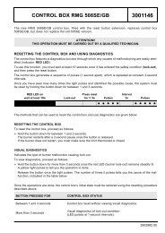
CAM. COMB. / FEUERRAUM mbarCOMB. CHAMBER / CHAMB. COMB.CAM. COMB. / FEUERRAUM mbarCOMB. CHAMBER / CHAMB. COMB.CAMPI DI LAVORO (A)La potenza del bruciatore v<strong>aria</strong> in funzionamentotra:• una POTENZA MASSIMA, scelta entro l’ area A,• e una POTENZA MINIMA, che non deveessere inferiore al limite minimo del <strong>di</strong>agramma:RS 70/M = 135 kWRS 100/M = 150 kWRS 130/M = 160 kWNotaPer utilizzare anche l’area B (RS 130/M) occorrela pretaratura della testa <strong>di</strong> combustione spiegataa pagina 14.AttenzioneIl CAMPO DI LAVORO è stato ricavato alla temperaturaambiente <strong>di</strong> 20 °C, alla pressione barometrica<strong>di</strong> 1000 mbar (circa 100 m s.l.m.) e conla testa <strong>di</strong> combustione regolata come in<strong>di</strong>cato apagina 16.CALDAIA DI PROVA (B)I campi <strong>di</strong> lavoro sono stati ricavati in specialicaldaie <strong>di</strong> prova, secondo la norma EN 676.Riportiamo in (B) <strong>di</strong>ametro e lunghezza dellacamera <strong>di</strong> combustione <strong>di</strong> prova.Esempio:Potenza 650 Mcal/h:<strong>di</strong>ametro 60 cm - lunghezza 2 m.CALDAIE COMMERCIALIL’abbinamento bruciatore-caldaia non pone problemise la caldaia è omologata CE e le <strong>di</strong>mensionidella sua camera <strong>di</strong> combustione sonovicine a quelle in<strong>di</strong>cate dal <strong>di</strong>agramma (B).Se, invece, il bruciatore deve essere applicato<strong>ad</strong> una caldaia commerciale non omologata CEe/o con <strong>di</strong>mensioni della camera <strong>di</strong> combustionenettamente più piccole <strong>di</strong> quelle in<strong>di</strong>cate dal <strong>di</strong>agramma(B), consultare i costruttori.(A)CAM. COMB. / FEUERRAUM mCOMB. CHAMBER / CHAMB. COMB.CAM. COMB. / FEUERRAUM mbarCOMB. CHAMBER / CHAMB. COMB.RS 70/MRS 100/MRS 130/MD882(B)D71510
REGELBEREICHE (A)Wahrend des Betriebs schwankt <strong>di</strong>e Brennerleistungzwischen:• einer HÖCHSTLEISTUNG, innerhalb des FeldesA gewählt,• und einer MINDESTLEISTUNG, <strong>di</strong>e nichtniedriger sein darf als <strong>di</strong>e Mindestgrenze desDiagramms.RS 70/M = 135 kWRS 100/M = 150 kWRS 130/M = 160 kWMerkeZur Anwendung von Feld B (RS 130/M) bedarfes der Voreinstellung des Flammfopfes gemäßBeschreibung auf Seite 15.AchtungDer REGELBEREICH wurde bei einer Raumtemperaturvon 20 °C, einem barometrischenDruck von 1000 mbar (ungefähr 100 m ü.d.M.)und bei wie auf Seite 17 eingestelltem Flammkopfgemessen.PRÜFKESSEL (B)Die Regelbereiche wurden an speziellen Prüfkesselnentsprechend Norm EN 676 ermittelt.In (B) sind Durchmesser und Länge der Prüfbrennkammerangegeben.Beispiel:Leistung 650 Mcal/h:Durchmesser = 60 cm, Länge = 2 m.HANDELSÜBLICHE KESSELDie Brenner-Kessel Kombination gibt keine Probleme,falls der Kessel "CE" - typgeprüft ist und<strong>di</strong>e Abmessungen seiner Brennkammer sichden im Diagramm (B) angegebenen nähern.Falls der Brenner dagegen an einem handelsüblichenKessel angebracht werden muß, dernicht "CE"-typgeprüft ist und/oder mit Abmessungender Brennkammer, <strong>di</strong>e entschieden kleinerals jene in Diagramm (B) angegebenensind, sollte der Hersteller zu Rate gezogen werden.FIRING RATES (A)During operation, burner output varies between:• a MAXIMUM OUTPUT, selected within area A,• and a MINIMUM OUTPUT, which must not belower than the minimum limit in the <strong>di</strong>agram.RS 70/M = 135 kWRS 100/M = 150 kWRS 130/M = 160 kWNoteIn order to utilize also area B (RS 130/M) it isnecessary to perform the calibration of the combustionhe<strong>ad</strong> as explained on page 15.ImportantThe FIRING RATE area values have beenobtained considering an ambient temperature of20 °C, and an atmospheric pressure of 1000mbar (approx. 100 m above sea level) and withthe combustion he<strong>ad</strong> <strong>ad</strong>justed as shown onpage 17.TEST BOILER (B)The firing rates were set in relation to specialtest boilers, accor<strong>di</strong>ng to EN 676 regulations.Figure (B) in<strong>di</strong>cates the <strong>di</strong>ameter and length ofthe test combustion chamber.Example:Output 650 Mcal/h:<strong>di</strong>ameter = 60 cm; length = 2.COMMERCIAL BOILERSThe burner/boiler combination does not poseany problems if the boiler is CE type-approvedand its combustion chamber <strong>di</strong>mensions aresimilar to those in<strong>di</strong>cated in <strong>di</strong>agram (B).If the burner must be combined with a commercialboiler that has not been Ce type-approvedand/or its combustion chamber <strong>di</strong>mensions areclearly smaller than those in<strong>di</strong>cated in <strong>di</strong>agram(B), consult the manufacturer.PLAGES DE PUISSANCE (A)La puissance du brûleur en fonctionnementvarie entre:• une PUISSANCE MAXIMUM, choisie dans laplage A,• et une PUISSANCE MINIMUM, qui ne doitpas être inférieure à la limite minimum du <strong>di</strong>agramme.RS 70/M = 135 kWRS 100/M = 150 kWRS 130/M = 160 kWNotaPour utiliser également la plage B (RS 130/M) ilest nécessaire de prérégler la tête de combustioncomme in<strong>di</strong>qué a page 15.Attention:La PLAGE DE PUISSANCE a été calculée àune température ambiante de 20 °C, à unepression barométrique de 1000 mbar (environ100 m au-dessus du niveau de la mer) et avecla tête de combustion réglée comme in<strong>di</strong>que lapage 17.CHAUDIERE D’ESSAI (B)Les plages de puissance ont été établies surdes chaiuières d’essai spéciales, selon la normeEN 676.Nous reportons fig.(B) le <strong>di</strong>amètre et la longueurde la chambre de combustion d’essai.Exempe:Puissance 650 Mcal/h:<strong>di</strong>amètre 60 cm - longueur 2 m.CHAUDIERES COMMERCIALESL’accouplement brûleur-chau<strong>di</strong>ère ne poseaucun problème si la chau<strong>di</strong>ère est homologuéeCE et si les <strong>di</strong>mensions de sa chambre de combustionsont proches de celles in<strong>di</strong>quées dansle <strong>di</strong>agramme (B).Par contre, si le brûleur doit être accouplé à unechau<strong>di</strong>ère commerciale non homologuée CE, et/ou avec des <strong>di</strong>mensions de chambre de combustionplus petites que celles in<strong>di</strong>quées dans le<strong>di</strong>agramme (B), consulter le constructeur.11
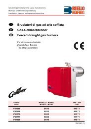
RS 70/MRS 100/MRS 130/M(A)kW 1 2Ø 1”1/23970145Ø 1”1/23970180∆p (mbar)Ø 2397022139702253∆p (mbar)∆p (mbar)Ø 239701813970182DN6539702223970226DN8039702233970227465 4,2 0,1 11,6 8,5 3,8 5,2 - -515 4,8 0,2 13,9 10,0 4,5 6,2 - -565 5,6 0,2 16,3 12,0 5,2 7,2 - -615 6,4 0,2 18,9 13,5 6,0 8,2 - -665 7,3 0,3 21,7 15,0 6,9 9,5 - -715 8,3 0,3 24,6 17,2 7,8 10,8 - -765 9,3 0,4 27,7 18,5 8,9 11,5 4,4 -814 10,3 0,4 30,9 20,0 9,7 13,0 5,0 -kW 1 2Ø 1”1/23970145Ø 1”1/23970180Ø 2397014639701603Ø 239701813970182DN6539701473970161DN8039701483970162695 3,7 0,4 23,5 17,0 7,4 10,1 - -760 4,2 0,4 27,4 18,5 8,7 11,5 4,4 -825 5,0 0,5 31,6 20,5 9,9 13,2 5,1 -890 5,8 0,5 36,1 23,0 11,3 14,0 5,8 -955 6,5 0,6 40,9 26,0 12,8 16,0 6,6 -1020 7,3 0,7 45,9 29,0 14,3 18,0 7,5 -1085 8,3 0,8 51,1 33,0 15,9 20,0 8,4 4,51163 9,3 0,8 57,7 38,0 17,9 22,0 9,5 5,0kW 1 2Ø 1”1/23970145Ø 1”1/23970180Ø 2397014639701603Ø 239701813970182DN6539701473970161DN8039701483970162930 3,8 1,0 39,0 22,0 12,2 15,0 6,3 -1010 4,5 1,1 44,9 28,0 14,0 17,0 7,4 -1090 5,1 1,3 51,5 33,0 16,0 20,0 8,5 4,51170 5,8 1,5 58,3 37,0 18,1 22,0 9,6 5,11250 6,5 1,7 65,4 40,0 20,2 25,0 10,8 5,71330 7,2 1,8 72,9 43,0 22,5 28,0 12,2 6,41410 7,9 1,9 80,7 48,0 24,8 31,0 13,6 7,11512 8,6 2,0 91,2 53,0 27,9 34,0 15,3 8,0PRESSIONE GASLe tabelle a lato in<strong>di</strong>cano le per<strong>di</strong>te <strong>di</strong> caricominime lungo la linea <strong>di</strong> alimentazione del <strong>gas</strong> infunzione della potenza massima del bruciatore.Colonna 1Per<strong>di</strong>ta <strong>di</strong> carico testa <strong>di</strong> combustione.Pressione del <strong>gas</strong> misurata alla presa 1)(B),con:• Camera <strong>di</strong> combustione a 0 mbar• Bruciatore funzionante alla potenza massima• Ghiera del <strong>gas</strong> 2)(B)p.16 regolata come <strong>di</strong>agramma(C)p.16.Colonna 2Per<strong>di</strong>ta <strong>di</strong> carico farfalla <strong>gas</strong> 2)(B) con aperturamassima: 90°.Colonna 3Per<strong>di</strong>ta <strong>di</strong> carico rampa 3)(B) comprendente:valvola <strong>di</strong> regolazione VR, valvola <strong>di</strong> sicurezzaVS (entrambe con apertura massima), regolatore<strong>di</strong> pressione R, filtro F.I valori riportati nelle tabelle si riferiscono a:<strong>gas</strong> naturale G 20 PCI 10 kWh/Nm 3 (8,6 Mcal/Nm 3 )Con:<strong>gas</strong> naturale G 25 PCI 8,6 kWh/Nm 3 (7,4 Mcal/Nm 3 )moltiplicare i valori delle tabelle per 1,3.Per conoscere la potenza approssimativa allaquale sta funzionando il bruciatore al MAX:- sottrarre dalla pressione del <strong>gas</strong> alla presa1)(B) la pressione in camera <strong>di</strong> combustione.- Trovare nella tabella relativa al bruciatoredesiderato, colonna 1, il valore <strong>di</strong> pressionepiù vicino al risultato della sottrazione.- Leggere sulla sinistra la potenza corrispondente.Esempio - RS 100/M:• Funzionamento alla potenza MAX• Gas naturale G 20 PCI 10 kWh/Nm 3• Ghiera del <strong>gas</strong> 2)(B)p.16 regolata come <strong>di</strong>agramma(C)p.16• Pressione del <strong>gas</strong> alla presa 1)(B) = 8 mbar• Pressione in camera combustione = 3 mbar8 - 3 = 5 mbarAlla pressione 5 mbar, colonna 1, corrispondenella tabella RS 100/M una potenza <strong>di</strong> 825 kW.Questo valore serve come prima approssimazione;la portata effettiva va misurata al contatore.Per conoscere invece la pressione del <strong>gas</strong>necess<strong>aria</strong> alla presa 1)(B), fissata la potenzaMAX alla quale si desidera funzioni il bruciatore:- trovare nella tabella relativa al bruciatore consideratoil valore <strong>di</strong> potenza più vicino alvalore desiderato.- Leggere sulla destra, colonna 1, la pressionealla presa 1)(B).- Sommare a questo valore la presunta pressionein camera <strong>di</strong> combustione.Esempio - RS 100/M:• Potenza MAX desiderata: 825 kW• Gas naturale G 20 PCI 10 kWh/Nm 3• Ghiera del <strong>gas</strong> 2)(B)p.16 regolata come <strong>di</strong>agramma(C)p.16• Pressione del <strong>gas</strong> alla potenza <strong>di</strong> 825 kW,dalla tabella RS 100/M, colonna 1 = 5 mbar• Pressione in camera combustione = 3 mbar5 + 3 = 8 mbarpressione necess<strong>aria</strong> alla presa 1)(B).(B)D88312
GASDRUCKIn den nebenstehenden Tabellen werden <strong>di</strong>eMindestströmungsverluste entlang der Gaszuleitungin Abhängigkeit der Höchstleistung desBrenners angezeigt.Spalte 1Strömungsverlust Flammkopf.Gasdruck am Anschluß 1)(B) gemessen, bei:• Brennkammer auf 0 mbar• Brennerbetrieb auf Höchstleistung• Gemäß Diagramm (C)S.16 eingestellter Gasscheibe2)(B)S.16.Spalte 2Strömungsverlust Gasdrossel 2)(B) bei maximalerÖffnung: 90°.Spalte 3Strömungsverlust Armaturen 3)(B) bestehendaus: Regelventil VR, Sicherheitsventil VS (beidebei maximaler Öffnung), Druckregler R, Filter F.Die Tabellenwerte beziehen sich auf:Erd<strong>gas</strong> G20 - Hu 10 kWh/Nm 3 (8,6 Mcal/Nm 3 )Bei:Erd<strong>gas</strong> G25 - Hu 8,6 kWh/Nm 3 (7,4 Mcal/Nm 3 )und Tabellenwerte mit 1,3 multiplizieren.Zur Ermittlung der ungefähren Brennerleistungim Betrieb auf der Höchstleistung des Brenners:- vom Gasdruck an der Entnahmestelle 1)(B)den Druck in der Brennkammer abziehen.- In der Tabelle des betreffenden Brenners,unter Spalte 1, den der Subtraktion nächstenWert ablesen.- Die entsprechende Leistung links ablesen.Beispiel - RS 100/M:• Betrieb auf Höchstleistung• Erd<strong>gas</strong> G20 - Hu 10 kWh/Nm 3• Gemäß Diagramm (C) S.16 eingestellte Gasscheibe2)(B)S.16• Gasdruck an der Entnahmestelle 1)(B) = 8 mbar• Druck in der Brennkammer = 3 mbar8 - 3 = 5 mbarDem Druck von 5 mbar, Spalte 1, entspricht inder Tabelle RS 100/M eine Leistung von 825kW.Dieser Wert <strong>di</strong>ent als erste Näherung; der tatsächlicheDurchsatz wird am Zähler abgelesen.Zur Ermittlung des für den an der Entnahmestelle1)(B) erforderlichen Gasdrucks, nachdem<strong>di</strong>e gewünschte Höchstleistung des Brennersfestgelegt wurde:- in der Tabelle des betreffenden Brenners <strong>di</strong>edem gewünschten Wert nächste Leistungsangabeablesen.- Rechts, unter der Spalte 1, den Druck an derEntnahmestelle 1)(B) ablesen.- Diesen Wert mit dem angenommenen Druckin der Brennkammer <strong>ad</strong><strong>di</strong>eren.Beispiel - RS 100/M:• Gewünschte Höchstleistung: 825 kW• Erd<strong>gas</strong> G20 - Hu 10 kWh/Nm 3• Gemäß Diagramm (C) S.16 eingestellte Gasscheibe2)(B)S.16• Gasdruck bei 825 kW Leistung, aus TabelleRS 100/M, Spalte 1 = 5 mbar• Druck in der Brennkammen = 3 mbar5 + 3 = 8 mbarErforderlicher Druck an der Entnahmestelle1)(B).GAS PRESSUREThe <strong>ad</strong>jacent tables show minimum pressurelosses along the <strong>gas</strong> supply line depen<strong>di</strong>ng onthe maximum burner output operation.Column 1Pressure loss at combustion he<strong>ad</strong>.Gas pressure measured at test point 1)(B), with:• Combustion chamber at 0 mbar• Burner operating at maximum output• Gas ring 2)(B)p.16 <strong>ad</strong>justed as in<strong>di</strong>cated in<strong>di</strong>agram (C)p.16.Column 2Pressure loss at <strong>gas</strong> butterfly valve 2)(B) withmaximum opening: 90°.Column 3Pressure loss of <strong>gas</strong> train 3)(B) includes: <strong>ad</strong>justmentvalve VR, safety valve VS (both fullyopen), pressure governor R, filter F.The values shown in the various tables refer to:natural <strong>gas</strong> G 20 PCI 10 kWh/Nm 3 (8,6 Mcal/Nm 3 )With:natural <strong>gas</strong> G 25 PCI 8,6 kWh/Nm 3 (7,4 Mcal/Nm 3 )multiply tabulated values by 1,3.Calculate the approximate maximum output ofthe burner thus:- subtract the combustion chamber pressurefrom the <strong>gas</strong> pressure measured at test point1)(B).- Find the nearest pressure value to your resultin column 1 of the table for the burner in question.- Re<strong>ad</strong> off the correspon<strong>di</strong>ng output on the left.Example - RS 100/M:• Maximum output operation• Natural <strong>gas</strong> G 20 PCI 10 kWh/Nm 3• Gas ring 2)(B)p.16 <strong>ad</strong>just as in<strong>di</strong>cated in <strong>di</strong>agram(C)p.16• Gas pressure at test point 1)(B) = 8 mbar• Pressure in combustion chamber = 3 mbar8 - 3 = 5 mbarA maximum output of 825 kW shown in TableRS 100/M corresponds to 5 mbar pressure, column1.This value serves as a rough guide, the effectivedelivery must be measured at the <strong>gas</strong> meter.To calculate the required <strong>gas</strong> pressure at testpoint 1)(B), set the maximim output requiredfrom the burner operation:- find the nearest output value in the table forthe burner in question.- Re<strong>ad</strong> off the pressure at test point 1)(B) onthe right in column 1.- Add this value to the estimated pressure inthe combustion chamber.Example - RS 100/M:• Required burner maximum output operation:825 kW• Natural <strong>gas</strong> G 20 PCI 10 kWh/Nm 3• Gas ring 2)(B)p.16 <strong>ad</strong>just as <strong>di</strong>agram (C)p.16• Gas pressure at burner output of 825 kW, takenfrom table RS 100/M, column 1 = 5 mbar• Pressure in combustion chamber = 3 mbar5 + 3 = 8 mbarpressure required at test point 1)(B).PRESSION DU GAZLes tableaux ci-contre in<strong>di</strong>quent les pertes decharge minimales sur la ligne d'alimentation engaz en fonction de la puissance maximum dubrûleur.Colonne 1Perte de charge tête de combustion.Pression du gaz mesurée à la prise 1)(B), avec:• Chambre de combustion à 0 mbar• Brûleur fonctionnant à la puissance maximum• Bague du gaz 2)(B)p.16 réglée selon le <strong>di</strong>agramme(C)p.16.Colonne 2Perte de charge vanne papillon gaz 2)(B) avecouverture maximum: 90°.Colonne 3Perte de charge de la rampe gaz 3)(B) comprenant:vanne de régulation VR, vanne de sûreteVS (ayant chacune une ouverture maximum),régulateur de pression R, filtre F.Les valeurs reportées sur les tableaux se réfèrentà:gaz naturel G 20 PCI 10 kWh/Nm 3 (8,6 Mcal/Nm 3 )Avec:gaz naturel G 25 PCI 8,6 kWh/Nm 3 (7,4 Mcal/Nm 3 )multiplier les valeurs des tableaux par 1,3.Pour connaître la puissance maximum approximativeà laquelle le brûleur fonctionne:- soustraire la pression dans la chambre decombustion de la pression du gaz à la prise1)(B).- Repérer la valeur la plus proche du résultatobtenu sur le tableau relatif au brûleur considéré,colonne 1.- Lire la puissance correspondante sur la gauche.Exemple - RS 100/M:• Fonctionnement à la puissance maximum• Gaz naturel G 20 PCI 10 kWh/Nm 3• Bague du gaz 2)(B)p.16 réglée selon le <strong>di</strong>agramme(C)p.16• Pression du gaz à la prise 1)(B) = 8 mbar• Pression en chambre de combustion = 3 mbar8 - 3 = 5 mbarSur le tableau RS 100/M à la pression de 5mbar, colonne 1, correspond une puissance de825 kW.Cette valeur sert de première approximation; ledébit effectif est mesuré sur le compteur.Par contre, pour connaître la pression du gaznécessaire à la prise 1)(B), après avoir fixé lapuissance maximum de fonctionnement du brûleur:- repérer la puissance la plus proche à lavaleur voulue dans le tableau relatif au brûleurconcerné.- Lire la pression à la prise 1)(B) sur la droite,colonne 1.- Ajouter à cette valeur la pression estiméedans la chambre de combustion.Exemple - RS 100/M:• Puissance maximum désirée: 825 kW• Gaz naturel G 20 PCI 10 kWh/Nm 3• Bague du gaz 2)(B)p.16 réglée selon le <strong>di</strong>agramme(C)p.16• Pression du gaz à la puissance de 825 kW, surle tableau RS 100/M, column 1 = 5 mbar• Pression dans la chambre de comb.= 3 mbar5 + 3 = 8 mbarpression nécessaire à la prise 1)(B).13
INSTALLAZIONEmm A B CRS 70/MRS 100/MRS 130/M185185195275 -325275 - 325275 - 325M 12M 12M 12PIASTRA CALDAIA (A)Forare la piastra <strong>di</strong> chiusura della camera <strong>di</strong>combustione come in (A). La posizione dei forifilettati può essere tracciata utilizzando loschermo termico a corredo del bruciatore.(A)D455LUNGHEZZA BOCCAGLIO (B)La lunghezza del boccaglio va scelta secondo lein<strong>di</strong>cazioni del costruttore della caldaia e, in ognicaso, deve essere maggiore dello spessoredella porta della caldaia, completa <strong>di</strong> refrattario.La lunghezza, L (mm), <strong>di</strong>sponibili sono:Boccaglio 12) RS 70/M RS 100/M RS 130/M• corto 250 250 280• lungo 385 385 415Per le caldaie con giro dei fumi anteriore 15), ocon camera <strong>ad</strong> inversione <strong>di</strong> fiamma, eseguireuna protezione in materiale refrattario 13), trarefrattario caldaia 14) e boccaglio 12).La protezione deve consentire al boccaglio <strong>di</strong>essere estratto.Per le caldaie con il frontale raffreddato <strong>ad</strong>acqua non è necessario il rivestimento refrattario13)-14), se non vi è espressa richiesta delcostruttore della caldaia.(B)Sonda - FühlerProbe - SondeElettrodo - ElektrodeElectrode - ElectrodeD884FISSAGGIO DEL BRUCIATORE ALLA CAL-DAIA (B)Prima <strong>di</strong> fissare il bruciatore alla caldaia, verificaredall’apertura del boccaglio se la sonda el’elettrodo sono correttamente posizionati comein (C).Separare quin<strong>di</strong> la testa <strong>di</strong> combustione dalresto del bruciatore, fig. (B):- allentare le 4 viti 3) e togliere il cofano 1);- sganciare lo snodo 7) dal settore gr<strong>ad</strong>uato 8);- togliere le viti 2) dalle due guide 5);- togliere le due viti 4) ed arretrare il bruciatoresulle guide 5) per circa 100 mm;- <strong>di</strong>sinserire i cavi <strong>di</strong> sonda ed elettrodo e quin<strong>di</strong>sfilare del tutto il bruciatore dalle guide.PRETARATURA TESTA DI COMBUSTIONEPer il modello RS 130/M verificare, a questopunto, se la portata massima del bruciatore in 2°sta<strong>di</strong>o è compresa nell’area A oppure in quellaB del campo <strong>di</strong> lavoro. Ve<strong>di</strong> pag.10.Se è nell’area A non occorre alcun untervento.Se invece è nell’area B:- svitare le viti 1)(D) e smontare il boccaglio 2);- spostare il fissaggio dell’asta 3)(D) dalla posizioneA a quella B, arretrando così l’otturatore4);- rimontare il boccaglio 2)(D) e le viti 1).Effettuata questa eventuale operazione, fissarela flangia 11)(B) alla piastra della caldaia interponendolo schermo isolante 9)(B) dato a corredo.Utilizzare le 4 viti pure date a corredodopo averne protetto la filettatura con prodottiantigrippanti.La tenuta bruciatore-caldaia deve essere ermetica.Se nel controllo precedente il posizionamentodella sonda o dell’elettrodo non è risultato corretto,togliere la vite 1)(E), estrarre la parteinterna 2)(E) della testa e provvedere alla lorotaratura.Non ruotare la sonda ma lasciarla come in (C);un suo posizionamento vicino all’elettrodod’accensione potrebbe danneggiare l’amplificatoredell’apparecchiatura.(C)D613(D)D738D718(E)14
INSTALLATIONKESSELPLATTE (A)Die Abdeckplatte der Brennkammer wie in (A)gezeigt vorbohren. Die Position der Gewindebohrungenkann mit der zur Grundausstattunggehörenden Wärmeschild ermittelt werden.FLAMMROHRLÄNGE (B)Die Länge des Flammrohrs wird entsprechendder Angaben des Kesselherstellers gewählt undmuß in jedem Fall länger sein, als <strong>di</strong>e Stärke derKesseltür feuerfestes Material sein. Die verfügbareLänge, L (mm), sind:Flammrohr 12) RS 70/M RS 100/M RS 130/M• kurz 250 250 280• lang 385 385 415Für Heizkessel mit vorderem Ab<strong>gas</strong>umlauf 15)oder Flammenumkehrkammer muß eineSchutzschicht aus feuerfestem Material 13),zwischen feuerfestem Material 14) und Flammrohr12) ausgefüht werden.Diese Schutzschicht muß so angelegt sein, daßdas Flammrohr ausbaubar ist.Für <strong>di</strong>e Kessel mit wassergekühlter Frontseiteist <strong>di</strong>e Verkleidung mit feuerfestem Material 13)-14) nicht notwen<strong>di</strong>g, sofern nicht ausdrücklichvom Kesselhersteller erfordert.BEFESTIGUNG DES BRENNERS AM HEIZ-KESSEL (B)Vor der Befestigung des Brenners am Heizkesselist von der Öffnung des Flammrohrs aus zuüberprüfen, ob der Fühler und <strong>di</strong>e Elektrodegemäß (C) in der richtigen Stellung sind.Dann den Flammkopf vom übrigen Brennertrennen, Abb. (B):- <strong>di</strong>e 4 Schrauben 3) lockern und <strong>di</strong>e Brennerhaube1) abnehmen;- das Gelenk 7) des Skalensegments 8) ausrasten;- <strong>di</strong>e Schrauben 2) von den zwei Führungen 5)abnehmen;- <strong>di</strong>e zwei Schrauben 4) abnehmen und denBrenner auf den Führungen 5) ca. 100 mm.nach hinten ziehen;- <strong>di</strong>e Fuhler- und Elektrodenkabel abtrennenund dann den Brenner komplett aus den Führungenziehen.VOREINSTELLUNG FLAMMKOPFBei Modell RS 130/M ist an <strong>di</strong>eser Stelle zuüberprüfen, ob der Höchstdurchsatz des Brennersauf 2. Stufe im Feld A bzw. B des Arbeitsbereichesliegt. Siehe Seite 10.Liegt er im Feld A, ist keine Regelung erforderlich.Liegt er dagegen im Feld B:- <strong>di</strong>e Schrauben 1)(D) abdrehen und dasFlammrohr 2) ausbauen;- <strong>di</strong>e Befestigung des Stabes 3)(D) von PositionA auf B umsetzen, d<strong>ad</strong>urch den Schieber4) zurücksetzen;- Flammrohr 2)(D) und Schrauben 1) wiederanbringen.Nach Abschluß <strong>di</strong>eses Regeleingriffes, denFlansch 11)(B) an der Kesseltür befestigen undden beigestellte Flansch<strong>di</strong>chtung 9)(B) dazwischenlegen.Die 4 ebenfalls beigepacktenSchrauben nach Auftragung von Freßschutzmittelnverwenden. Es muß <strong>di</strong>e Dichtheit von Brenner-Kesselgewährleistet sein.Hat <strong>di</strong>e vorausgehende Positionsprüfung vonFühler oder Elektrode einen Fehler ergeben, <strong>di</strong>eSchraube 1)(E) abnehmen, das Innenteil 2)(E)des Kopfs herausziehen und eine neue Einstellungvornehmen.Den Fühler nicht drehen, sondern wie in (C) lassen;seine Positionierung in der Nähe der Zündelektrodekönnte den Geräteverstärkerbeschä<strong>di</strong>gen.INSTALLATIONBOILER PLATE (A)Drill the combustion chamber locking plate asshown in (A). The position of the thre<strong>ad</strong>ed holescan be marked using the thermal screen suppliedwith the burner.BLAST TUBE LENGTH (B)The length of the blast tube must be selectedaccor<strong>di</strong>ng to the in<strong>di</strong>cations provided by themanufacturer of the boiler, and in any case itmust be greater than the thickness of the boilerdoor complete with its fettling. The length available,L (mm), is as follows:Blast tube 12) RS 70/M RS 100/M RS 130/M• short 250 250 280• long 385 385 415For boilers with front flue passes 15) or flameinversion chambers, protective fettling in refractorymaterial 13), must be inserted between theboiler fettling 14) and the blast tube 12).This protective fettling must not compromise theextraction of the blast tube.For boilers having a water-cooled front therefractory fettling 13)-14) is not required unlessit is expressly requested by the boiler manufacturer.SECURING THE BURNER TO THE BOILER (B)Before securing the burner to the boiler, checkthrough the blast tube opening to make surethat the flame sensor probe and the ignitionelectrode are correctly set in position, as shownin (C).Now detach the combustion he<strong>ad</strong> from theburner, fig. (B):- loosen the four screws 3) and remove thecover 1);- <strong>di</strong>sengage the articulated coupling 7) from thegr<strong>ad</strong>uated sector 8);- remove the screws 2) from the slide bars 5);- remove the two screws 4) and pull the burnerback on slide bars 5) by about 100 mm;- <strong>di</strong>sconnect the wires from the probe and theelectrode and then pull the burner completelyoff the slide bars.COMBUSTION HEAD CALIBRATIONAt this point check, for model RS 130/M,whether the maximum delivery of the burner in2nd stage operation is contained in area A or inarea B of the firing rate. See page 10.If it is in area A then no operation is required.If, on the other hand, it is in area B:- unscrew the screws 1)(D) and <strong>di</strong>sassemblethe blast tube 2);- move the fixing of the rod 3)(D) from positionA to position B, thereby causing the shutter 4)to retract;- now refit the blast tube 2)(D) and the screws1).Once this operation has been carried out (if itwas required), secure the flange 11)(B) to theboiler plate, interposing the thermal insulatingscreen 9)(B) supplied with the burner. Use the 4screws, also supplied with the unit, after firstprotecting the thre<strong>ad</strong> with an anti-locking product.The seal between burner and boiler must beairtight.If you noticed any irregularities in positions ofthe probe or ignition electrode during the checkmentioned above, remove screw 1)(E), extractthe internal part 2)(E) of the he<strong>ad</strong> and proceedto set up the two components correctly.Do not attempt to turn the probe. Leave it in theposition shown in (C) since if it is located tooclose to the ignition electrode the control boxamplifier may be damaged.INSTALLATIONPLAQUE CHAUDIERE (A)Percer la plaque de fermeture de la chambre decombustion comme sur la fig. (A). La positiondes trous filetés peut être tracée en utilisantl'écran thermique fourni avec le brûleur.LONGUEUR BUSE (B)La longueur de la buse doit être choisie selonles in<strong>di</strong>cations du constructeur de la chau<strong>di</strong>ère,en tout cas, elle doit être supérieure à l'épaisseurde la porte de la chau<strong>di</strong>ère, matériauréfractaire compris. La longueur, L (mm), <strong>di</strong>sponiblesont:Buse 12) RS 70/M RS 100/M RS 130/M• courte 250 250 280• longue 385 385 415Pour les chau<strong>di</strong>ères avec circulation desfumées sur l'avant 15), ou avec chambre àinversion de flamme, réaliser une protection enmatériau réfractaire 13), entre réfractaire chau<strong>di</strong>ère14) et buse 12).La protection doit permettre l'extraction de labuse.Pour les chau<strong>di</strong>ères dont la partie frontale estrefroi<strong>di</strong>e par eau, le revêtement réfractaire 13)-14)(B) n'est pas nécessaire, sauf in<strong>di</strong>cation precisedu constructeur de la chau<strong>di</strong>ère.FIXATION DU BRULEUR A LA CHAUDIERE (B)Avant de fixer le brûleur à la chau<strong>di</strong>ère, vérifierpar l'ouverture de la buse si la sonde et l'électrodesont positionnées correctement commein<strong>di</strong>qué en (C).Séparer ensuite la tête de combustion du restedu brûleur, fig. (B):- desserrer les 4 vis 3) et extraire le coffret 1);- décrocher la rotule 7) du secteur gr<strong>ad</strong>ué 8);- retirer les vis 2) des deux guides 5);- retirer les vis 4) et faire reculer le brûleur surles guides 5) d'environ 100 mm;- détacher les câbles de la sonde et de l'électrode,enlever ensuite complètement le brûleurdes guides.PREREGLAGE TETE DE COMBUSTIONPour le modèle RS 130/M vérifier, à ce st<strong>ad</strong>e, sile débit maximum du brûleur en 2me allure estcompris dans la plage A ou B de la plage depuissance. Voir page 10.Si ce débit appartient à la plage A aucune interventionn’est nécessaire.Si ce débit est dans la plage B:- dévisser les vis 1)(D) et démonter la buse 2);- déplacer la fixation de la tige 3)(D) de la positionA à la position B, en reculant de cettefaçon l’obturateur 4);- remonter la buse 2)(D) et les vis 1).Une fois cette opération effectuée, fixer la bride11)(B) à la plaque de la chau<strong>di</strong>ère en interposantl'écran isolant 9)(B) fourni de série. Utiliserles 4 vis également de série après en avoir protégéle filetage par du produit antigrippant.L'étanchéité brûleur-chau<strong>di</strong>ère doit être parfaite.Si, lors du contrôle précédent, le positionnementde la sonde ou de l'électrode n'était pas correct,retirer la vis 1)(E), extraire la partie interne 2)(E)de la tête et tarer celles-ci. Ne pas faire pivoterla sonde mais la laisser en place comme in<strong>di</strong>quéen (C); son positionnement dans le voisinagede l'électrode d'allumage pourraitendommager l'amplificateur de l'appareil.15
REGOLAZIONE TESTA DI COMBUSTIONEA questo punto dell’installazione, boccaglio emanicotto sono fissati alla caldaia come in fig.(A). È quin<strong>di</strong> particolarmente agevole la regolazionedelle testa <strong>di</strong> combustione, regolazioneche <strong>di</strong>pende unicamente dalla potenza massim<strong>ad</strong>el bruciatore.Perciò, prima <strong>di</strong> regolare la testa <strong>di</strong> combustione,bisogna fissare questo valore.Sono previste due regolazioni della testa:quella dell’<strong>aria</strong> e quella del <strong>gas</strong>.Trovare nel <strong>di</strong>agramma (C) la tacca alla qualeregolare sia <strong>aria</strong> che <strong>gas</strong> e quin<strong>di</strong>:Regolazione <strong>aria</strong> (A)Ruotare la vite 4)(A) fino a far collimare la taccatrovata con il piano anteriore 5)(A) della flangia.Regolazione <strong>gas</strong> (B)Allentare le 3 viti 1)(B) e ruotare la ghiera 2) finoa far collimare la tacca trovata con l’in<strong>di</strong>ce 3).Bloccare le 3 viti 1).(A)D719(B)D720(C)(D)N° Tacche (<strong>aria</strong>=<strong>gas</strong>) / Kerben (Luft=Gas) / Notches (Air=Gas) / Encoches (Air=Gaz)Potenza max bruciatoreHöchstbrennerleistungMax burner outputPuissance maxi du brûleurD885Esempio RS 70/MPotenza MAX bruciatore = 500 Mcal/h.Dal <strong>di</strong>agramma (C) risulta che per questapotenza le regolazioni del <strong>gas</strong> e dell’<strong>aria</strong> vannoeffettuate sulla tacca 3, come in fig. (A) e (B).NotaIl <strong>di</strong>agramma (C) in<strong>di</strong>ca la regolazione ottimaledella ghiera 2)(B). Se la pressione nella rete <strong>di</strong>alimentazione del <strong>gas</strong> è molto bassa e non consenteil raggiungimento della pressione in<strong>di</strong>cataa pag. 12 alla potenza MAX, e se la ghiera 2)(B)è solo parzialmente aperta, è possibile aprireulteriormente la ghiera <strong>di</strong> 1-2 tacche.Continuando l’esempio precedente, a pag. 12 sivede che per un bruciatore RS 70/M conpotenza <strong>di</strong> 500 Mcal/h (581 kW) occorrono 6mbar circa <strong>di</strong> pressione alla presa 6)(A). Sequesta pressione non è <strong>di</strong>sponibile, aprire laghiera 2)(B) a 4-5 tacche.Controllare che la combustione sia sod<strong>di</strong>sfacentee priva <strong>di</strong> pulsazioni.Terminata la regolazione della testa, rimontare ilbruciatore sulle guide 3)(D) a circa 100 mm dalmanicotto 4)(D) - bruciatore nella posizione illustrat<strong>ad</strong>alla fig. (B)p.14 - inserire il cavo dellasonda ed il cavo dell’elettrodo e quin<strong>di</strong> far scorrereil bruciatore fino al manicotto, bruciatorenella posizione illustrata dalla fig. (D).Rimettere le viti 2) sulle guide 3).Fissare il bruciatore al manicotto con le viti 1).Riagganciare lo snodo 7) al settore gr<strong>ad</strong>uato 6).AttenzioneAll’atto della chiusura del bruciatore sulle dueguide, è opportuno tirare delicatamente versol’esterno il cavo d’alta tensione ed il cavettodella sonda <strong>di</strong> rivelazione fiamma, fino a metterliin leggera tensione.16
EINSTELLUNG DES FLAMMKOPFSAn <strong>di</strong>eser Stelle der Installation sind das Flammrohrund <strong>di</strong>e Muffe gem. Abb. (A) am Kesselbefestigt. Die Einstellung des Flammkopfs istdaher besonders bequem, sie hängt von derHöchstbrennerleistung.Dieser Wert muß daher unbe<strong>di</strong>ngt vor der Einstellungdes Flammkopfs festgelegt werden.Am Flammkopf sind zwei Einstellungen vorgesehen:<strong>di</strong>e Lufteinstellung und <strong>di</strong>e Gaseinstellung.In Diagramm (C) <strong>di</strong>e Kerbe ausfin<strong>di</strong>ng machen,auf <strong>di</strong>e Luft und Gas einzustellen sind, dann:Lufteinstellung (A)Die Schraube 4)(A) drehen, bis <strong>di</strong>e gefundeneKerbe mit der Vorderfläche 5)(A) des Flanscheszusammenfällt.Gaseinstellung (B)Die drei Schrauben 1)(B) lockern und <strong>di</strong>eScheibe 2) soweit drehen, bis <strong>di</strong>e gefundeneKerbe mit dem Indexstift 3) zusammenfält.Die drei Schrauben 1) blockieren.Beispiel RS 70/MHöchstbrennerleistung = 500 Mcal/h.Dem Diagramm (C) wird entnommen, daß <strong>di</strong>eGas- und Lufteinstellungen für <strong>di</strong>esen Leistungsbereichauf der Kerbe 3 auszuführensind, wie in Abb. (A) und (B) gezeigt.MerkeDas Diagramm (C) zeigt <strong>di</strong>e optimale Einstellungder Scheibe 2)(B). Falls der Gaszuleistungsdruckbesonders niedring ist und d<strong>ad</strong>urchder auf Seite 12 angegebene Druck in derHöchstleistung nicht erreicht werden kann, undfalls <strong>di</strong>e Scheibe 2)(B) nur teilweise geöffnet ist,kann <strong>di</strong>e leztere um weitere 1-2 Kerben geöffnetwerden.Entsprechend <strong>di</strong>esem Beispiel ist auf Seite 12ersichtlich, daß ein Brenner RS 70/M mit 500Mcal/h (581 kW) Leistung ca. 6 mbar Druck ander Entnahmestelle 6)(A) erfordert. Liegt <strong>di</strong>eserDruck nicht an, <strong>di</strong>e Scheibe 2)(B) auf <strong>di</strong>e 4-5Kerbe öffnen.Die Verbrennung muß zufriedenstellend undohne Verpuffungen erfolgen.Nach Beendung der Flammkopfeinstellung denBrenner auf <strong>di</strong>e Führungen 3)(D) in ca. 100 mmAbstand zur Brennerkopf 4)(D) - einbauen -Brennerposition in Abb. (B)S.14 - das FühlerundElektrodenkabel einsetzen und anschließendden Brenner bis zur Muffe schieben, Brennerpositionin Abb. (D).Die Schrauben 2) auf <strong>di</strong>e Führungen 3) einsetzen.Den Brenner anhand den Schrauben 1) an demBrennerkopf befestigen.Das Gelenk 7) wieder am Skalensegment 6)einhängen.Wichtiger HinweisBeim Schließen des Brenners ist es ratsam, dasHochspannungskabel und das Kabel des Flammenfühlersvorsichtig nach außen zu ziehen, bissie leicht gespannt sind.COMBUSTION HEAD SETTINGInstallation operations are now at the stagewhere the blast tube and sleeve are secured tothe boiler as shown in fig. (A). It is now a verysimple matter to set up the combustion he<strong>ad</strong>, asthis depends solely on the MAX output developedby the burner.It is therefore essential to establish this valuebefore procee<strong>di</strong>ng to set up the combustionhe<strong>ad</strong>.There are two <strong>ad</strong>justments to make on thehe<strong>ad</strong>:air and <strong>gas</strong> deliveries.In <strong>di</strong>agram (C) find the notch to use for <strong>ad</strong>justingthe air and the <strong>gas</strong>, and then proceed as follows:Air <strong>ad</strong>justment (A)Turn screw 4)(A) until the notch identified isaligned with the front surface 5)(A) of the flange.Gas <strong>ad</strong>justment (B)Loosen the 3 screws 1)(B) and turn ring 2) untilthe notch identified is aligned with index 3).Tighten the 3 screws 1) fully down.Example RS 70/MMAX output = 500 Mcal/h.If we consult <strong>di</strong>agram (C) we find that for thisoutput, air must be <strong>ad</strong>justed using notch 3, asshown in figs. (A) and (B).NoteDiagramm (C) shows the ideal settings for thering 2)(B). If the <strong>gas</strong> mains pressure is too lowto reach the max output operation pressure in<strong>di</strong>catedon page 12, and if the ring 2)(B) is not fullyopen, it can be opened wider by 1 or 2 notches.Continuing with the previous example, page 12in<strong>di</strong>cates that for burner RS 70/M with output of500 Mcal/h (581 kW) a pressure of approximately6 mbar is necessary at test point 6)(A). Ifthe pressure cannot be reached, open the ring2)(B) to notch 4 or 5.Make sure that the combustion characteristicsare satisfactory and free of pulsations.Once you have finished setting up the he<strong>ad</strong>, refitthe burner to the slide bars 3)(D) at approximately100 mm from the sleeve 4)(D) - burnerpositioned as shown in fig. (B)p.14 - insert theflame detection probe cable and the ignitionelectrode cable and then slide the burner up tothe sleeve so that it is positioned as shown infig. (D).Refit screws 2) on slide bars 3).Secure the burner to the sleeve by tighteningscrew 1).Reconnect the articulation 7) to the gr<strong>ad</strong>uatedsector 6).ImportantWhen fitting the burner on the two slide bars, itis <strong>ad</strong>visable to gently draw out the high tensioncable and flame detection probe cable until theyare slightly stretched.REGLAGE TETE DE COMBUSTIONA ce st<strong>ad</strong>e de l'installation, buse et manchonsont fixés à la chau<strong>di</strong>ère comme in<strong>di</strong>qué sur lafig. (A). Le réglage de la tête de combustion estdonc particulièrement facile, et dépend uniquementde la puissance MAX développée par lebrûleur.C'est pourquoi, il faut fixer cette valeur avant derégler la tête de combustion.Deux réglages de la tête sont prévus:le réglage de l’air et celui du gaz.Trouver sur le <strong>di</strong>agramme (C) l’encoche surlaquelle régler l’air et le gaz.Réglage de l'air (A)Faire pivoter la vis 4)(A) jusqu'à faire correspondrel'encoche trouvée avec le plan antérieur5)(A) de la bride.Réglage du gaz (B)Desserrer les 3 vis 1)(B) et faire tourner labague 2) jusqu’à faire correspondre l’encocheavec le repère 3).Bloquer les vis 1)Exemple RS 70/MPuissance MAX = 500 Mcal/h.Le <strong>di</strong>agramme (C) in<strong>di</strong>que que pour cette puissancele réglages du gaz et de l’air seront effectuéssur l’encoche 3, comme in<strong>di</strong>qué sur la fig.(A) et (B).NoteLe <strong>di</strong>agramme (C) in<strong>di</strong>que le réglage optimal dela bague 2)(B). Si la pression du réseau d’alimentationen gaz est très faible et ne permetpas d’atteindre la pression in<strong>di</strong>quée page 12 à lapuissance maximum, et si la bague 2)(B) n’estouverte qu’en partie, il est possible d’ouvirencore cette bague de 1 ou 2 encoches.Pour continuer l'exemple précédent, la page 12in<strong>di</strong>que que pour un brûleur RS 70/M de puissance500 Mcal/h (581 kW) il faut 6 mbar environde pression à la prise 6)(A). Si cettepression n’est pas <strong>di</strong>sponible, ouvrir la bague2)(B) de 4 ou 5 encoches.Contrôler que la combustion soit satisfaisante etsans sacc<strong>ad</strong>esUne fois terminé le réglage de la tête, remonterle brûleur sur les guides 3)(D) à environ 100 mmdu manchon 4)(D) - brûleur dans la positionillustrée fig. (B)p. 14 - insérer les câbles de lasonde et de l'électrode et ensuite faire coulisserle brûleur jusqu'au manchon, brûleur dans laposition illustrée fig. (D).Replacer les vis 2) sur les guides 3).Fixer le brûleur au manchon avec la vis 1).Raccrocher la rotule 7) au secteur gr<strong>ad</strong>ué 6).AttentionAu moment de la fermeture du brûleur sur lesdeux guides, il faut tirer délicatement vers l'extérieurle câble de haute tension et le petit câblede la sonde de détection flamme, jusqu'à cequ'ils soient légèrement tendus.17
(A)D722LINEA ALIMENTAZIONE GAS• La rampa del <strong>gas</strong> va collegata all’attacco del<strong>gas</strong> 1)(A), tramite la flangia 2), la guarnizione3) e le viti 4) date a corredo del bruciatore.• La rampa può arrivare da destra o da sinistra,secondo como<strong>di</strong>tà, ve<strong>di</strong> fig. (A).• Le elettrovalvole 8)-9)(B) del <strong>gas</strong> devonoessere il più vicino possibile al bruciatore inmodo da assicurare l'arrivo del <strong>gas</strong> alla testa<strong>di</strong> combustione nel tempo <strong>di</strong> sicurezza <strong>di</strong> 2 s.• Assicurarsi che il campo <strong>di</strong> taratura del regolatore<strong>di</strong> pressione (colore della molla) comprendala pressione necess<strong>aria</strong> al bruciatore.RAMPA GAS (B)E' omologata secondo norma EN 676 e vienefornita separatamente dal bruciatore con ilco<strong>di</strong>ce in<strong>di</strong>cato in tab. (C).(B)D893BRUCIATORI E RELATIVE RAMPE GAS OMOLOGATE SECONDO NORMA EN 676BRENNER UND ZUGEHÖRIGE NACH EN 676 TYPGEPRÜFTE GASARMATURENBURNERS AND RELEVANT GAS TRAINS APPROVED ACCORDING TO EN 676BRÛLEURS ET RELATIVES RAMPES GAZ HOMOLOGUÉES SELON LA NORME EN 676Rampa <strong>gas</strong> - GasarmaturenGas trains - Rampe gaz LBruciatore - BrennerBurner - Brûleur13 14Ø C.T. Code RS 70/M RS 100/M RS 130/M Code Code- 3970145 • • • 3010123 30008431”1/2- 3970180 • • • 3010123 3000843- 3970146 • • • 3010123 -♦ 3970160 • • • --2”- 3970181 • • • 3010123 -♦ 3970182 • • • --- 3970147 • • • 3010123 3000825DN 65♦ 3970161 • • • - 3000825DN 80-♦39701483970162(C)COMPONENTI RAMPA GAS - BESTANDTEILE GASARMATURENGAS TRAINS COMPONENTS - COMPOSANTS RAMPE GAZ----••3010123-30008263000826Componenti - Bestandteile - Components - ComposantsCOD.5 6 7 - 83970145 GF 515/1 FRS 515 DMV-DLE 512/113970180 Multiblock MB DLE 41539701463970160GF 520/1 FRS 520 DMV-DLE 520/1139701813970182Multiblock MB DLE 42039701473970161GF 40065/3 FRS 5065 DMV-DLE 5065/1139701483970162GF 40080/3 FRS 5080 DMV-DLE 5080/11LEGENDA (B)1 - Condotto arrivo del <strong>gas</strong>2 - Valvola manuale3 - Giunto antivibrante4 - Manometro con rubinetto a pulsante5 - Filtro6 - Regolatore <strong>di</strong> pressione (verticale)7 - Pressostato <strong>gas</strong> <strong>di</strong> minima8 - Elettrovalvola <strong>di</strong> sicurezza VS (verticale)9 - Elettrovalvola <strong>di</strong> regolazione VR (verticale)Due regolazioni:• portata d'accensione (apertura rapida)• portata massima (apertura lenta)10 - Guarnizione e flangia a corredo bruciatore11 - Farfalla regolazione <strong>gas</strong>12 - Bruciatore13 - Dispositivo <strong>di</strong> controllo tenuta valvole 8)-9).Secondo la norma EN 676 il controllo <strong>di</strong>tenuta è obbligatorio per i bruciatori conpotenza massima superiore a 1200 kW;quin<strong>di</strong> solo per il modello RS 130/M.14 - Adattatore rampa-bruciatore15 - Pressostato <strong>gas</strong> <strong>di</strong> massimaP1 - Pressione alla testa <strong>di</strong> combustioneP2 - Pressione a valle del regolatoreP3 - Pressione a monte del filtroL - Rampa <strong>gas</strong> fornita a parte con il co<strong>di</strong>cein<strong>di</strong>cato in tab. (C).L1 - A cura dell'installatoreLEGENDA TABELLA (C)C.T.= Dispositivo controllo tenuta valvole <strong>gas</strong>8) - 9):- = Rampa priva del <strong>di</strong>spositivo <strong>di</strong> controllotenuta; <strong>di</strong>spositivo che puòessere or<strong>di</strong>nato a parte, ve<strong>di</strong> colonna13, e montato successivamente.♦= Rampa con il <strong>di</strong>spositivo <strong>di</strong> controllotenuta VPS montato.13 = Dispositivo <strong>di</strong> controllo tenuta valvoleVPS.Fornito su richiesta separatamente dallarampa <strong>gas</strong>.14 = Adattatore rampa-bruciatore.Fornito su richiesta separatamente dallarampa <strong>gas</strong>.NotaPer la regolazione della rampa <strong>gas</strong> vedere leistruzioni che l'accompagnano.18
GASZULEITUNG• Gasarmaturen sind über Flansch 2), Dichtung3) und Schrauben 4), zur Brennerausstattunggehörend, mit dem Gasanschluß 1)(A) zu verbinden.• Die Armatur kann je nach Bedarf von rechtsbzw. links zugeführt werden, s. Abb. (A).• Die Magnetventile 8)-9)(B) der Gaszuleistungsollen so nah wie möglich am Brenner liegen,damit <strong>di</strong>e Gaszufuhr zum Flammkopf innerhalb2 Sekunden sichergestellt ist.• Überprüfen, ob der Einstellbereich des Druckreglers(Farbe der Feder) <strong>di</strong>e für den Brennererforderlichen Druckwerte vorsieht.GASARMATUREN (B)Nach Norm EN 676 typgeprüft, wird gesondertmit dem in Tab. (C) angegebenen Code geliefert.ZEICHENERKLÄRUNG (B)1 - Gaszuleitung2 - Handbetätigtes Ventil3 - Kompensator4 - Manometer mit Druckknopfhahn5 - Filter6 - Druckregler (senkrecht)7 - Gas-Minimaldruckwächter8 - Sicherheitsmagnetventil VS (senkrecht)9 - Regelmagnetventil VR (senkrecht)Zwei Einstellungen:• Zünddurchsatz (schnellöffnend)• Max. Durchsatz (langsamöffnend)10 - Dichtung und Flansch Brennergrundausstattung11 - Gas-Einstelldrossel12 - Brenner13 - Dichtheitskontrolleinrichtung der Gasventile8)-9). Laut Norm EN 676 ist <strong>di</strong>e Dichtheitskontrollefür Brenner mitHöchstleistung über 1200 kW Pflicht; dahernur für <strong>di</strong>e Modell RS 130/M.14 - Passtück Armatur-Brenner15 - Gas-HöchstdruckwächterP1 - Druck am FlammkopfP2 - Druck nach dem ReglerP3 - Druck vor dem FilterL - Gasarmatur gesondert mit dem in Tab. (C)angegebenen Code geliefert.L1 - Vom Installateur auszuführenZEICHENERKLÄRUNG TABELLE (C)C.T.= Dichtheitskontrolleinrichtung der Gasventile8) - 9):- = Gasarmatur ohne Dichtheitskontrolleinrichtung;<strong>di</strong>e Einrichtung kanngesondert bestellt, siehe Spalte 13,und später eingebaut werden.♦= Gasarmatur mit der eingebautenDichtheitskontrolleinrichtung VPS.13 = Dichtheitskontrolleinrichtung VPS derGasventile.Auf Anfrage gesondert von der Gasarmaturlieferbar.14 = Passtück Armatur-Brenner.Auf Anfrage gesondert von der Gasarmaturlieferbar.MerkeZur Einstellung der Gasarmaturen siehe <strong>di</strong>e beigelegtenAnleitungen.GAS LINE• The <strong>gas</strong> train must be connected to the <strong>gas</strong>attachment 1)(A), using flange 2), <strong>gas</strong>ket 3)and screws 4) supplied with the burner.• The <strong>gas</strong> train can enter the burner from theright or left side, depen<strong>di</strong>ng on which is themost convenient, see fig. (A).• The <strong>gas</strong> solenoids 8)-9)(A) must be as closeas possible to the burner to ensure <strong>gas</strong>reaches the combustion he<strong>ad</strong> within the safetytime range of 2 s.• Make sure that the pressure governor calibrationrange (colour of the spring) comprises thepressure required by the burner.GAS TRAIN (A)It is type-approved accor<strong>di</strong>ng to EN 676 Standardsand is supplied separately from the burnerwith the code in<strong>di</strong>cated in Table (C).KEY (A)1 - Gas input pipe2 - Manual valve3 - Vibration damping joint4 - Pressure gauge with pushbutton cock5 - Filter6 - Pressure governor (vertical)7 - Minimum <strong>gas</strong> pressure switch8 - Safety solenoid VS (vertical)9 - Adjustment solenoid VR (vertical)Two <strong>ad</strong>justments:• ignition delivery (rapid opening)• maximum delivery (slow opening)10 - Standard issue burner with flange <strong>gas</strong>ket11 - Gas <strong>ad</strong>justment butterfly valve12 - Burner13 - Gas valve 8)-9) leak detection controldevice.In accordance with EN 676 Standards, <strong>gas</strong>valve leak detection control devices arecompulsory for burners with maximum outputsof more than 1200 kW; therefore onlyfor model RS 130/M.14 - Gas train/burner <strong>ad</strong>aptor15 - Maximum <strong>gas</strong> pressure switchP1 - Pressure at combustion he<strong>ad</strong>P2 - Pressure down-line from the pressure governorP3 - Pressure up-line from the filterL - Gas train supplied separately with the codein<strong>di</strong>cated in table (C)L1 - The responsibility of the installerKEY TO TABLE (C)C.T.= Gas valves 8) - 9) leak detection controldevices:- = Gas train without <strong>gas</strong> valve leakdetection control device; device thatcan be ordered separately andassembled subsequently (see Column13).♦= Gas train with assembled VPS valveleak detection control device.13 = VPS valve leak detection control device.Supplied separately from <strong>gas</strong> train onrequest.14 = Gas train/burner <strong>ad</strong>aptor.Supplied separately from <strong>gas</strong> train onrequest.NoteSee the accompanying instructions for the<strong>ad</strong>justment of the <strong>gas</strong> train.LIGNE ALIMENTATION GAZ• La rampe du gaz doit être reliée au raccord dugaz 1)(A), par la bride 2), le joint 3) et les vis 4)fournis de série avec le brûleur.• La rampe peut arriver par la droite ou par lagauche selon les cas, comme in<strong>di</strong>qué sur lafig. (A).• Les électrovannes 8)-9)(B) du gaz doivent êtrele plus près possible du brûleur de façon àassurer l'arrivée du gaz à la tête de combustionen un temps de sécurité de 2 s.• Contrôler que la plage de réglage du régulateurde pression (couleur du ressort) recouvrela pression nécessaire au brûleur.RAMPE GAZ (B)Elle est homologuée suivant la norme EN 676 etelle est fournie séparément du brûleur avec lecode in<strong>di</strong>qué dans le tableau (C).LEGENDA (B)1 - Canalisation d'arrivée du gaz2 - Vanne manuelle3 - Joint anti-vibrations4 - Manomètre avec robinet à bouton poussoir5 - Filtre6 - Régulateur de pression (vertical)7 - Pressostat gaz de seuil minimum8 - Electrovanne de sécurité VS (verticale)9 - Electrovanne de régulation VR (verticale)Deux réglages:• débit d'allumage (ouverture rapide)• débit maximum (ouverture lente)10 - Joint et bride fournis avec le brûleur11 - Papillon réglage gaz12 - Brûleur13 - Dispositif de contrôle d'étanchéité vannes8)-9).Selon la norme EN 676, le contrôle d'étanchéitéest obligatoire pour les brûleursayant une puissance maximale supérieureà 1200 kW; donc seulement pour le modéleRS 130/M.14 - Adaptateur rampe-brûleur15 - Pressostat gaz seuil maximumP1 - Pression à la tête de combustionP2 - Pression en aval du régulateurP3 - Pression en amont du filtreL - La rampe gaz est fournie à part avec lecode in<strong>di</strong>qué dans le tab. (C).L1 - A la charge de l'installateurLEGENDE TABLEAU (C)C.T.= Dispositif de contrôle d'étanchéité vannes8)-9):- = Rampe sans <strong>di</strong>spositif de contrôled'étanchéité; <strong>di</strong>spositif qui peut êtrecommandé à part et monté par lasuite, voir colonne 13.♦= Rampe avec <strong>di</strong>spositif de contrôled'étanchéité VPS monté.13 = Dispositif VPS de contrôle d'étanchéitéde la vanne.Fourni sur demande séparément de larampe gaz.14 = Adaptateur rampe-brûleur.Fourni sur demande séparément de larampe gaz.NotePour le réglage de la rampe gaz voir les instructionsqui l'accompagnent.19
RS 70/M - RS 100/M - RS 130/MIMPIANTO ELETTRICO ESEGUITO IN FABBRICAWERKSEITIG AUSGEFÜHRTE ELEKTROANLAGEELECTRICAL EQUIPMENT FACTORY-SETINSTALLATION ELECTRIQUE REALISEE EN USINE(A)D913IMPIANTO ELETTRICOIMPIANTO ELETTRICO eseguito in fabbricaSCHEMA (A)Bruciatore RS 70-100-130/M• Il modello RS 70-100-130/M lasciano la fabbricaprevisti per alimentazione elettrica 400 V.• Se l'alimentazione è 230 V, cambiare il collegamentodel motore (da stella a triangolo) e lataratura del relè termico.LEGENDA SCHEMA (A)CMV - Contattore motoreF1 - Filtro contro ra<strong>di</strong>o<strong>di</strong>sturbiLFL 1.3.. - Apparecchiatura elettricaMB - Morsettiera bruciatoreMV - Motore ventilatorePA - Pressostato <strong>aria</strong>PGM - Pressostato <strong>gas</strong> <strong>di</strong> massimaRT - Relè termicoS1 - Interruttore per funzionamento:MAN = manualeAUT = automaticoOFF = spentoS2 - Pulsante per- = <strong>di</strong>minuzione potenza+ = aumento potenzaSM - ServomotoreSO - Sonda <strong>di</strong> ionizzazioneSP - Spina-presaTA - Trasformatore d'accensioneTB - Terra bruciatore20
ELEKTROANLAGEELEKTROANLAGE werkseitig ausgeführtSCHEMA (A)Brenner RS 70-100-130/M• Die Modelle RS 70-100-130/M werden werkseitigfür 400 V Stromversorgung vorbereitet.• Falls <strong>di</strong>e Stromversorgung 230 V beträgt, denMotoranschluß (Stern- oder Dreieckschaltung)und <strong>di</strong>e Einstellung des Überstromauslöserverändern.ERLÄUTERUNG SCHEMA (A)CMV - MotorkontaktgeberF1 - FunkentstörerLFL 1.3.. - SteuergerätMB - Klemmenbrett BrennerMV - GebläsemotorPA - LuftdruckwächterPGM - Gas-HöchstdruckwächterRT - ÜberstromauslöserS1 - Schalter für:MAN = Manueller BetriebAUT = Automatischer BetriebOFF = AUSS2 - Schalter für:- = Leistungsabminderung+ = LeistungserhöhungSM - StellantriebSO - IonisationselektrodeSP - SteckanschlußTA - ZündtransformatorTB - BrennererdungELECTRICAL SYSTEMELECTRICAL SYSTEM as set up by the manufacturerLAYOUT (A)Burner RS 70-100-130/M• Models RS 70-100-130/M leave the factorypreset for 400 V power supply.•If 230 V power supply is used, change themotor connection from star to delta andchange the setting of the thermal cut-out aswell.KEY TO LAYOUT (A)CMV - Motor contactorF1 - Protection against ra<strong>di</strong>o interferenceLFL 1.3.. - Control boxMB - Burner terminal stripMV - Fan motorPA - Air pressure switchPGM - Maximum <strong>gas</strong> pressure switchRT - Thermal cut-outS1 - Switch for following operations:MAN = manualAUT = automaticOFFS2 - Button for:- = power reduction+ = power increaseSM - ServomotorSO - Ionisation probeSP - Plug-socketTA - Ignition transformerTB - Burner groundINSTALLATION ELECTRIQUEINSTALLATION ELECTRIQUE effectué enusineSCHEMA (A)Brûleur RS 70-100-130/M• Le modèle RS 70-100-130/M triphasés quittentl'usine prévus pour une alimentation électriqueà 400 V.• Si l'alimentation est à 230 V, mo<strong>di</strong>fier le branchementdu moteur (d'étoile à triangle) et leréglage du relais thermique.LÉGENDE SCHÉMAS (A)CMV - Contacteur moteurF1 - Protection contre parasites ra<strong>di</strong>oLFL 1.3.. - Coffret de sécuritéMB - Porte-bornes brûleursMV - Moteur ventilateurPA - Pressostat airPGM - Pressostat gaz seuil maximumRT - Relais thermiqueS1 - Interrupteur pour le fonctionner:MAN = manuelAUT = automatiqueOFF = éteintS2 - Bouton-poussoir pour:- = <strong>di</strong>minution puissance+ = augmentation puissanceSM - ServomoteurSO - Sonde d'ionisationSP - Fiche-priseTA - Transformateur d'allumageTB - Mise à la terre brûleur21
COLLEGAMENTI ELETTRICIUsare cavi flessibili secondo norma EN 60 335-1:• se sotto guaina <strong>di</strong> PVC almeno tipo H05 VV-F• se sotto guaina <strong>di</strong> gomma almeno tipo H05RR-F.Tutti i cavi da collegare alla morsettiera 9)(A) delbruciatore vanno fatti passare dai passacavi.L'utilizzo dei passacavi può avvenire in varimo<strong>di</strong>; a scopo esemplificativo in<strong>di</strong>chiamo ilmodo seguente:(A)D886RS 70/M - RS 100/M - 130/MSENZA DISPOSITIVO DI CONTROLLO TENUTA VALVOLE GASOHNE DICHTHEITKONTROLLEINRICHTUNGENWITHOUT LEAK DETECTION CONTROL DEVICESANS DISPOSITIF DE CONTROLE D’ETANCHEITE1- Pg 13,5 Alimentazione trifase2- Pg 11 Alimentazione monofase3- Pg 11 Telecomando TL4- Pg 9 Telecomando TR o sonda(RWF40)5- Pg 13,5 Valvole <strong>gas</strong>(Quando non è montato il controllo<strong>di</strong> tenuta RG1/CT o LDU 11)6- Pg 13,5 Pressostato <strong>gas</strong> o <strong>di</strong>spositivo per ilcontrollo <strong>di</strong> tenuta valvole7- Pg 11 Forare, se si desidera aggiungereun bocchettoneSCHEMA (B)Allacciamento elettrico bruciatori RS 70-100-130/M senza controllo tenuta valvole <strong>gas</strong>.SCHEMA (C)Allacciamento elettrico bruciatori RS 70-100-130/M con controllo tenuta valvole <strong>gas</strong> VPS.Il controllo tenuta valvole <strong>gas</strong> avviene subitoprima <strong>di</strong> ogni avviamento del bruciatore.Fusibile schemi (B-C), ve<strong>di</strong> tab. (D).Sezione cavi non in<strong>di</strong>cata: 1,5 mm 2 .(B)D1357RS 70/M - RS 100/M - 130/MCON DISPOSITIVO DI CONTROLLO TENUTA VALVOLE GASMIT DICHTHEITKONTROLLEINRICHTUNGENWITH LEAK DETECTION CONTROL DEVICEAVEC DISPOSITIF DE CONTROLE D’ETANCHEITELEGENDA SCHEMI (B) - (C)IN - Interruttore elettrico per arresto manualebruciatoreMB - Morsettiera bruciatoreXP - Spina per controllo <strong>di</strong> tenutaPG - Pressostato <strong>gas</strong> <strong>di</strong> min.S - Segnalazione <strong>di</strong> blocco a <strong>di</strong>stanzaS1 - Segnalazione <strong>di</strong> blocco del controllo <strong>di</strong>tenuta a <strong>di</strong>stanzaTR - Telecomando <strong>di</strong> regolazione:comanda potenza minima e massima.TL - Telecomando <strong>di</strong> limite:ferma il bruciatore quando la temperaturao la pressione in caldaia raggiunge ilvalore prestabilito.TS - Telecomando <strong>di</strong> sicurezza:interviene in caso <strong>di</strong> TL guasto.VR - Valvola <strong>di</strong> regolazioneVS - Valvola <strong>di</strong> sicurezzaNotaI telecoman<strong>di</strong> TR e TL non sono necessariquando è collegato il RWF40 per funzionamentomodulante; la loro funzione viene svolta dalregolatore stesso.D1358(C)RS 70/M RS 100/M RS 130/M230 V 400 V 230 V 400 V 230 V 400 VF A T10 T6 T16 T10 T16 T10L mm 2 1,5 1,5 1,5 1,5 1,5 1,5(D)22
RS 70-100-130/MCON DISPOSITIVO DI CONTROLLO TENUTA VALVOLE GAS RG1/CT RIELLOMIT DICHTHEITSKONTROLLEINRICHTUNGEN RG1/CT RIELLOWITH RG1/CT RIELLO LEAK DETECTION CONTROL DEVICEAVEC DISPOSITIF DE CONTROLE D’ETANCHEITE RG1/CT RIELLO(A)(C)RWF40(E)D786RS 70-100-130/MCON DISPOSITIVO DI CONTROLLO TENUTA VALVOLE GAS LDU 11 LANDISMIT DICHTHEITSKONTROLLEINRICHTUNGEN LDU 11 LANDISWITH LDU 11 LANDIS LEAK DETECTION CONTROL DEVICEAVEC DISPOSITIF DE CONTROLE D’ETANCHEITE LDU 11 LANDISD787a - d : Rosso Rot Red Rougeb - c : Bianco Weiss White BlancRELÈ TERMICOTHERMORELAISTHERMAL RELAYRELAIS THERMIQUED1910(B)(D)SCHEMA (A)Allacciamento elettrico bruciatore RS 70-100-130/M con controllo tenuta valvole <strong>gas</strong>RG1/CT RIELLO.Il controllo tenuta valvole <strong>gas</strong> avviene subitoprima <strong>di</strong> ogni avviamento del bruciatore.SCHEMA (C)Allacciamento elettrico RS 70-100-130/M concontrollo tenuta valvole <strong>gas</strong> LDU 11 LANDIS.Il controllo tenuta valvole <strong>gas</strong> avviene subitoprima <strong>di</strong> ogni avviamento del bruciatore.SCHEMA (B) - (D)Se si preferisce che il <strong>di</strong>spositivo RG1/CT oLDU 11 controlli la tenuta delle valvole <strong>gas</strong>subito dopo l’arresto del bruciatore, collegare TLed il <strong>di</strong>spositivo come in (B) - (D).Legenda schemi (A) - (B) - (C) - (D) - (E)BT - Sonda <strong>di</strong> temperaturaBP - Sonda <strong>di</strong> pressioneIN - Interruttore elettrico per arresto manualebruciatoreMB - Morsettiera bruciatorePC - Pressostato <strong>gas</strong> per controllo <strong>di</strong> tenutaPG - Pressostato <strong>gas</strong> <strong>di</strong> min.S - Segnalazione <strong>di</strong> blocco a <strong>di</strong>stanzaTR - Telecomando <strong>di</strong> regolazione: comandapotenza minima e massima.TL - Telecomando <strong>di</strong> limite: ferma il bruciatorequando la temperatura o la pressione in caldaiaraggiunge il valore prestabilito.TS - Telecomando <strong>di</strong> sicurezza: interviene incaso <strong>di</strong> TL guasto.VR - Valvola <strong>di</strong> regolazioneVS - Valvola <strong>di</strong> sicurezzaFusibili schemi (A) e (C), ve<strong>di</strong> tab. (D)p.22.Sezione cavi non in<strong>di</strong>cata: 1,5 mm 2 .SCHEMA (E)Allacciamento regolatore <strong>di</strong> potenza RWF40 erelativa sonda ai bruciatori RS 70-100-130/M(funzionamento modulante)NotaI telecoman<strong>di</strong> TR e TS non sono necessariquando è collegato il RWF40 per funzionamentomodulante; la loro funzione viene svolta dalRWF40 stesso. Il relè k1 (RWF40) può esserecollegato ai morsetti:- 2 - 3, per sostituire il telecomando TL- AL - AL1,per comandare un <strong>di</strong>spositivo <strong>di</strong>allarmeSCHEMA (F)Taratura rele' termico 8)(A)p.8Serve <strong>ad</strong> evitare la bruciatura del motore per unforte aumento dell'assorbimento dovuto allamancanza <strong>di</strong> una fase.• Se il motore è alimentato a stella, 400 V, il cursoreva posizionato sul "MIN".• Se è alimentato a triangolo, 230 V, il cursoreva posizionato sul "MAX".Se la scala del relè termico non comprendel'assorbimento <strong>di</strong> targa del motore a 400 V, laprotezione è assicurata lo stesso.NotaI modelli RS 70-100-130/M lasciano la fabbrica previstiper alimentazione elettrica 400 V. Se l'alimentazioneè 230 V, cambiare il collegamento del motore(da stella a triangolo) e la taratura del relè termico.I bruciatori RS 70-100-130/M sono stati omologatiper funzionamento intermittente. Ciò significache devono fermarsi "per Norma" almeno 1volta ogni 24 ore per permettere all'apparecchiaturaelettrica <strong>di</strong> effettuare un controllo dellapropria efficienza all'avviamento. Normalmentel'arresto del bruciatore viene assicurato dal telecomandodella caldaia.Se così non fosse è necessario applicare inserie a IN un interruttore orario che provvedaall'arresto del bruciatore almeno 1 volta ogni 24ore.Questi bruciatori sono <strong>ad</strong>atti anche al funzionamentocontinuo se vengono equipaggiati conl’apparecchiatura Lan<strong>di</strong>s LGK 16.333 A27 (intercambiabilecon l’apparecchiatura Lan<strong>di</strong>s LFL1.333 del bruciatore).ATTENZIONE:Non invertire il neutro con la fase nella linea<strong>di</strong> alimentazione elettrica.(F)D86724
SCHEMA (A)Elektrischer Brenneranschluß RS 70-100-130/M mit DichtheitskontrolleinrichtungenRG1/CT RIELLO.Die Dichtheitskontrolle der Gasventile erfolgtumgehend vor jedem Brennerstart.SCHEMA (C)Elektrischer Brenneranschluß RS 70-100-130/M mit DichtheitskontrolleinrichtungenLDU 11 LANDIS.Die Dichtheitskontrolle der Gasventile erfolgtumgehend vor jedem Brennerstart.SCHEMEN (B) - (D)Falls es vorgezogen wird, daß <strong>di</strong>e Einrichtung RG1/CT oder LDU 11 <strong>di</strong>e Dichtheit der Gasventileumgehend nach dem Anhalten des Brenners kontrolliert,TL und <strong>di</strong>e Einrichtung wie in (B) - (D) anscließen.Zeichenerklärung Schemen (A) - (B) - (C) - (D) - (E)BT - TemperaturfühlerBP - DruckfühlerIN- Schalter für das manuelle Ausschaltendes BrennersMB - Klemmenbrett BrennerPC - Gasdruckwächter für DichtheitskontrollePG - Gas-MindestdruckwächterS - Fernmeldung StörabschaltungTR - Einstell-Fernsteuerung: steuert MindestundHöchstleistung.TL - Begrenzungsfernsteuerung: schaltet denBrenner aus, wenn <strong>di</strong>e Temperatur oder derKesseldruck den festgelegten Wert erreichen.TS - Sicherheitsfernsteuerung:tritt bei Defekt an TL in Aktion.VR - RegelventilVS - SicherheitsventilSicherungen Schemen (A) - (C), s. tab. (D) S. 22.Nicht angegebener Kabelquerschnitt: 1,5 mm 2 .SCHEMA (E)Elektroanschluß des Leistungsreglers RWF40und des entsprechenden Fühlers an <strong>di</strong>e BrennerRS 70-100-130/M (modulierender Betrieb)MerkeWenn das RWF40 angeschlossen ist, sind <strong>di</strong>eFernsteuerungen TR und TL nicht erforderlich, d<strong>ad</strong>eren Funktionen vom RWF40 übernommen werden.Das Relais k1 (RWF40) kann an <strong>di</strong>e Klemmen:- 2 - 3 zum Ersatz der Fernsteuerung TL- AL - AL1, zur Steuerung einer Alarmvorrichtungangeschloßen werden.SCHEMA (F)Einstellung Wärmerelais 8)(A)S.8Dieser schützt den Motor vor dem Durchbrennenwegen erhöhter Stromaufnahme bei Ausfalleneiner Phase.• Wenn der Motor über eine Sternschaltung mit400 V- gesteuert wird, muß der Zeiger auf"MIN"- Stellung positioniert werden.• Bei Dreieck-Schaltung mit 230 V- Spannung,muß der Zeiger auf "MAX" gestellt werden.Obwohl <strong>di</strong>e Skala des Überstromauslösers nicht<strong>di</strong>e Entnahmewerte vorsieht, <strong>di</strong>e auf demTypenschild des 400 V-Motors angegeben sind,wird der Schutz trotzdem gewährleistet.AnmerkungenDie Brenner RS 70-100-130/M wird werkseitigfür 400 V Stromversorgung vorbereitet. Falls <strong>di</strong>eStromversorgung 230 V beträgt, den Motoranschluß(Stern- oder Dreieckschaltung) und <strong>di</strong>eEinstellung des Überstromauslöser verändern.Der Brenner RS 70-100-130/M sind für intermittierendenBetrieb typgeprüft. Das bedeutet, daßsie - laut Vorschrift - wenigstens einmal pro 24Stunden ausgeschaltet werden müssen, damit<strong>di</strong>e Steuergeräte eine Prüfung ihrer Functionstüchtigkeitbei Anfahren durchführen konnen.Das Ausschalten erfolgt gewöhnlich über <strong>di</strong>eFernsteuerung des Kessels.Sollte <strong>di</strong>es nicht der Fall sein, muß an IN einZeitschalter reihengeschaltet werden, der einBrennerausschalten einmal in 24 Stundengewährleistet.Wenn <strong>di</strong>ese Brenner mit dem GasfeuerungsautomatenLan<strong>di</strong>s & Gyr LGK 16.333 A27 (mitdem Gerät Lan<strong>di</strong>s LFL 1.333 des Brenners austauschbar)ausgestattet sind, sind sie auch fürden Dauerbetrieb geeignet.ACHTUNG: Den Nulleiter nicht mit demPhasenleiter in der Leitung der Stromversorgungvertauschen.LAYOUT (A)The RS 70-100-130/M Models electrical connectionpower supply with RG1/CT RIELLOleak detection control device.Gas valve leak detection control takes placeimme<strong>di</strong>ately before every burner starting.LAYOUT (C)The RS 70-100-130/M Models electrical connectionpower supply with LDU 11 LANDISleak detection control device.Gas valve leak detection control takes placeimme<strong>di</strong>ately before every burner starting.LAYOUTS (B) - (D)If it is preferable that the RG1/CT or LDU 11device controls the sealing of valves imme<strong>di</strong>atelyafter burner shut-down, connect TL andthe device as shown in (B) - (D).Key to layouts (A) - (B) - (C) - (D) - (E)BT - Temperature probeBP - Pressure probeIN - Burner manual stop switchMB - Burner terminal stripPC - Gas pressure switch for leak detectioncontrol devicePG - Min. <strong>gas</strong> pressure switchS - Remote lock-out signalTR - High-low mode lo<strong>ad</strong> remote control system:controls min. and max. output.TL - Lo<strong>ad</strong> limit remote control system: shutsdown the burner when the boiler temperatureor pressure reaches the preset value.TS - Safety lo<strong>ad</strong> control system: operates whenTL is faulty.VR - Adjustment valveVS - Safety valveFuses layouts (A) - (C), see table (D) page 22.Cross-section when not in<strong>di</strong>cated: 1,5 mm 2 .LAYOUT (E)Connection of RWF40 and related probe toRS 70-100-130/M burner (modulating operation).NoteThe TR and TL lo<strong>ad</strong> controls are not requiredwhen the RWF40 is connected, as their functionis performed by the RWF40 itself.The thermal cutout k1 (RWF40) can be connectedto the terminals:- 2 - 3, to replace the remote control TL- AL - AL1, to control an alarm device.LAYOUT (F)Calibration of thermal cut-out 8)(A)p.8This is required to avoid motor burn-out in theevent of a significant increase in power absorptioncaused by a missing phase.• If the motor is star-powered, 400 V, the cursorshould be positioned to "MIN".• If the motor is delta-powered, 230 V, the cursorshould be positioned to "MAX".Even if the scale of the thermal cut-out does notinclude rated motor absorption at 400 V, protectionis still ensured in any case.NoteModels RS 70-100-130/M leaves the factorypreset for 400 V power supply. If 230 V powersupply is used, change the motor connectionfrom star to delta and change the setting of thethermal cutout as well.Models RS 70-100-130/M have been typeapprovedfor intermittent operation. This meansthey should compulsorily be stopped at leastonce every 24 hours to enable the control box tocheck its own efficiency at start-up. Burner haltsare normally provided for automatically by theboiler lo<strong>ad</strong> control system.If this is not the case, a time switch should be fitte<strong>di</strong>n series to IN to provide for burner shut-down atleast once every 24 hours.These burners are also fitted for the continuosoperation, if they are equipped with the controlbox Lan<strong>di</strong>s type LGK 16.333 A27 (interchangeablewith the burner control box Lan<strong>di</strong>s LFL1.333).WARNING: Do not invert the neutral with thephase wire in the electricity supply line.SCHEMA (A)Branchement électrique brûleurs RS 70-100-130/M avec <strong>di</strong>spositif de contrôle d'étanchéitéRG1/CT RIELLO.Le contrôle d'étanchéité des vannes se fait justeavant chaque mise en marche du brûleur.SCHEMA (C)Branchement électrique brûleurs RS 70-100-130/M avec <strong>di</strong>spositif de contrôle d'étanchéitéLDU 11 LANDIS.Le contrôle d'étanchéité des vannes se fait justeavant chaque mise en marche du brûleur.SCHEMAS (B) - (D)Si l’on préfère que le <strong>di</strong>spisitif RG1/CT ouLDU11 contrôle l’étanchéité des vannes aussitôtaprès l’arrêt du brûleur, raccorder TL et le <strong>di</strong>spositifcomme en (B) - (D).Légende schémas (A) - (B) - (C) - (D) - (E)BT - Sonde de températureBP - Sonde de pressionIN - Interrupteur électrique pour arrêt manuelbrûleurMB - Porte-bornes brûleurPC - Pressostat gaz pour contrôle d'étanchéitéPG - Pressostat gaz seuil minimumS - Signalisation blocage brûleur à <strong>di</strong>stanceTR - Télécommande de réglage:commande puissance minimum et maximum.TL - Télécommande de limite:arrête le brûleur quand la température oula pression dans la chau<strong>di</strong>ère a atteint lavaleur fixée.TS - Télécommande de sécurité:intervient quand le TL tombe en panne.VR - Vanne de réglageVS - Vanne de sécuritéFusibles schemas (A) et (C), voir tab. (D) page22.Section câbles non in<strong>di</strong>quée: 1,5 mm 2 .LAYOUT (E)Branchement électrique régulateur de puissanceRWF40 et sonde correspondant au brûleurs RS70-100-130/M (fonctionnement modulant).RemarqueLes télécommandes TR et TL ne sont pasnécessaires quand le RWF40, pour fonctionnementmodulant, est branché: leur fonction estassurée par le RWF40 proprement <strong>di</strong>t.Le ralais k1 (RWF40) peut être relié aux bornes:- 2 - 3, pour remplacer la télécommande TL- AL - AL1, pour commander un <strong>di</strong>spositif d’alarme.SCHEMA (F)Réglage relais thermique 8)(A)p.8Sert à éviter que le moteur brûle à cause d’uneforte augmentation de l'absorption due àl'absence d'une phase.• Si le moteur est alimenté en étoile, 400 V, lecurseur doit être placé sur "MIN".• S'il est alimenté en triangle, 230 V, le curseurdoit être placé sur "MAX".Si l'échelle du relais thermique ne comprend pasl'absorption in<strong>di</strong>quée sur la plaque du moteur à400 V, la protection est assurée quand même.RemarqueLes modèles RS 70-100-130/M quittent l'usineprévu pour l'alimentation électrique à 400 V. Sil'alimentation est à 230 V, changer la connexiondu moteur (d'étoile à triangle) et le réglage durelais thermique.Les modèles RS 70-100-130/M ont été homologuéspour fonctionner de façon intermittente.Cela veut <strong>di</strong>re qu'ils doivent s'arrêter selon lesnormes au moins 1 fois toutes les 24 heurespour permettre au boîtier d'effectuer un contrôlede son efficacité au moment du démarrage.Normalement l'arrêt du brûleur est assuré par lethermostat de la chau<strong>di</strong>ère.S'il n'en était pas ainsi, il faudrait appliquer ensérie au IN un interrupteur horaire qui commanderaitl'arrêt du brûleur au moins 1 fois toutesles 24 heures.Ces brûleurs sont in<strong>di</strong>qués aussi pour le fonctionnementpermanent, s’ils sont équipés avecle boîtier Lan<strong>di</strong>s type LGK 16.333 A27 (interchangeableavec lle boîtier, Lan<strong>di</strong>s type LFL1.333, du brûleur).ATTENTION: Dans la ligne d'alimentation électrique,ne pas inverser le neutre avec la phase.25
PRESSOSTATO GAS DI MIN.GAS-MINDESTDRUCKWÄCHTERMIN GAS PRESSURE SWITCHPRESSOSTAT GAZ MINIMUM(A)PRESSOSTATO GAS DI MAX.GAS-HÖCHSTDRUCKWÄCHTERMAX GAS PRESSURE SWITCHPRESSOSTAT GAZ MAXIMUMD896 D66 D521(B)PRESSOSTATO ARIALUFT-DRUCKWÄCHTERAIR PRESSURE SWITCHPRESSOSTAT AIR(C)REGOLAZIONI PRIMA DELL'ACCENSIONELa regolazione della testa <strong>di</strong> combustione, <strong>aria</strong> e<strong>gas</strong>, è già stata descritta a pag. 16.Altre regolazioni da fare sono:- aprire le valvole manuali poste a monte dellarampa del <strong>gas</strong>.- Regolare il pressostato <strong>gas</strong> <strong>di</strong> minima all'inizioscala (A).- Regolare il pressostato <strong>gas</strong> <strong>di</strong> massima a finescala (B).- Regolare il pressostato <strong>aria</strong> all'inizio scala (C).- Sfiatare l'<strong>aria</strong> dalla tubazione del <strong>gas</strong>.E' consigliabile portare all'esterno dell'e<strong>di</strong>ficiocon un tubo in plastica l'<strong>aria</strong> sfiatata fino <strong>ad</strong>avvertire l'odore del <strong>gas</strong>.- Montare un manometro a U (D) sulla presa <strong>di</strong>pressione del <strong>gas</strong> del manicotto.Serve a ricavare approssimativamente lapotenza MAX del bruciatore me<strong>di</strong>ante letabelle <strong>di</strong> pag. 12.- Collegare in parallelo alle due elettrovalvoledel <strong>gas</strong> due lampa<strong>di</strong>ne o tester per controllareil momento dell'arrivo della tensione.Questa operazione non è necess<strong>aria</strong> seognuna delle due elettrovalvole è munita <strong>di</strong>una spia luminosa che segnala la tensioneelettrica.Prima <strong>di</strong> accendere il bruciatore, è opportunoregolare la rampa del <strong>gas</strong> in modo che l'accensioneavvenga nelle con<strong>di</strong>zioni <strong>di</strong> massima sicurezzae cioè con una piccola portata <strong>di</strong> <strong>gas</strong>.SERVOMOTORE (E)Il servomotore regola contemporaneamente laserranda dell'<strong>aria</strong> tramite la camma a profilov<strong>aria</strong>bile e la farfalla del <strong>gas</strong>.Compie una rotazione <strong>di</strong> 130° in 42 s.Non mo<strong>di</strong>ficare la regolazione fatta in fabbricaalle 5 camme <strong>di</strong> cui è dotato; solo controllareche esse siano come sotto riportato:Camma I : 130°Limita la rotazione verso il massimo. Con il bruciatorefunzionante alla potenza MAX la farfall<strong>ad</strong>el <strong>gas</strong> deve risultare tutta aperta: 90°.Camma I I : 0°Limita la rotazione verso il minimo.A bruciatore spento la serranda dell'<strong>aria</strong> e la farfall<strong>ad</strong>el <strong>gas</strong> devono risultare chiuse: 0°.Camma I I I : 20°Regola la posizione <strong>di</strong> accensione e potenza MIN.Camma I V - V : non utilizzate(D)SERVOMOTORESTELLANTRIEBSERVOMOTORSERVOMOTREURD888AVVIAMENTO BRUCIATOREChiudere i telecoman<strong>di</strong> e mettere l’interruttore1)(F) in posizione “MAN”.Appena il bruciatore si avvia controllare il senso<strong>di</strong> rotazione della girante del ventilatore dalvisore fiamma 13)(A)p.8.Verificare che le lampa<strong>di</strong>ne o i tester collegatialle elettrovalvole, o le spie luminose sulle elettrovalvolestesse, in<strong>di</strong>chino assenza <strong>di</strong> tensione.Se segnalano tensione, fermare imme<strong>di</strong>atamenteil bruciatore e controllare i collegamentielettrici.(E)(F)1 2D791D887ACCENSIONE BRUCIATOREDopo aver fatto quanto descritto al punto precedente,il bruciatore dovrebbe accendersi. Seinvece il motore si avvia ma non compare lafiamma e l'apparecchiatura va in blocco, sbloccareed attendere un nuovo tentativo d'avviamento.Se l'accensione continua a mancare può essereche il <strong>gas</strong> non arrivi alla testa <strong>di</strong> combustioneentro il tempo <strong>di</strong> sicurezza <strong>di</strong> 3 s.Aumentare allora la portata del <strong>gas</strong> all'accensione.L'arrivo del <strong>gas</strong> al manicotto è evidenziato dalmanometro <strong>ad</strong> U (D).Ad accensione avvenuta, passare alla completaregolazione del bruciatore.26
EINSTELLUNGEN VOR DER ZÜNDUNGDie Einstellung des Flammkopfs, von Luft undGas, ist bereits auf Seite 17 beschrieben worden.Weitere Einstellungen sind:- kugelhähne vor der Gasarmatur öffnen.- Den Gas-Mindestdruckwächter auf den Skalenanfangswert(A) einstellen.- Den Gas-Höchstdruckwächter auf den Skalenanfangwert(B) einstellen.- Den Luft-Druckwächter auf den Skalenanfangswert(C) einstellen.- Die Luft von der Gasleitung entlüften.Es wird empfohlen, <strong>di</strong>e abgelassene Luft übereinen Kunststoffschlauch ins Freie abzuführen,bis der Gasgeruch wahrnehmbar ist.- Ein U Manometer (D) auf den Gasanschlußder Muffe einbauen.Hiermit wird <strong>di</strong>e ungefähre Höchstleistungdes Brenners anhand der Tabellen auf Seite12 ermittelt.- Parallel zu den beiden Gas-Magnetventilenzwei Glühbirnen oder einen Tester anschließen,um den Zeitpunkt der Spannungszufuhrzu überprüfen.Dieses Verfahren ist nicht notwen<strong>di</strong>g, falls <strong>di</strong>ebeiden Elektroventile mit einer Kontrollampeausgestattet sind, <strong>di</strong>e <strong>di</strong>e Elektrospannunganzeigt.Vor dem Zünden des Brenners sind <strong>di</strong>e Gasarmaturenso einzustellen, daß <strong>di</strong>e Zündung unterBe<strong>di</strong>ngungen höchster Sicherheit bei einemgeringen Gasdurchsatz erfolgt.STELLANTRIEB (E)Über den Nocken mit v<strong>aria</strong>blem Profil steuertder Stellantrieb gleichzeitig <strong>di</strong>e Luftklappe und<strong>di</strong>e Gasdrossel.Er führt in 42 s eine 130° Drehung aus.Die werkseitige Einstellung seiner 5 Nockennicht verändern; es sollte nur <strong>di</strong>e Entsprechungzu folgenden Angaben überprüft werden:Nocken I : 130°Begrenzt <strong>di</strong>e Drehung zum Höchstwert.Bei Brennerbetrieb auf Höchstleistung muß <strong>di</strong>eGasdrossel ganz geöffnet sein: 90°.Nocken I I : 0°Begrenzt <strong>di</strong>e Drehung zum Mindestwert.Bei ausgeschaltetem Brenner müssen <strong>di</strong>e Luftklappeund <strong>di</strong>e Gasdrossel geschlossen sein: 0°.Nocken I I I : 20°Regelt <strong>di</strong>e Zünd- und Mindestleistungsposition.Nocken I V - V : nicht verwendetANFAHREN DES BRENNERSDie Fernsteuerungen einschalten und denSchalter 1)(F) in Stellung “MAN” setzen.Nach Anfahren des Brenners <strong>di</strong>e Drehrichtungdes Gebläser<strong>ad</strong>es durch das Sichtfenster13)(A)S. 8 überprüfen.Kontrollieren, daß an den an <strong>di</strong>e Magnetventileangeschlossenen Kontrollampen und Spannungsmessern,oder an den Kontrollampen aufden Elektroventilen, keine Spannung anliegt.Wenn Spannung vorhanden ist, sofort denBrenner ausschalten und <strong>di</strong>e Elektroanschlüsseüberprüfen.ZÜNDUNG DES BRENNERSWenn alle vorab angeführten Anleitungenbeachtet worden sind, müßte der Brenner zünden.Wenn hingegen der Motor läuft, aber <strong>di</strong>eFlamme nicht erscheint und eine Geräte-Störabschaltungerfolgt, entriegeln und das Anfahrenwiederholen.Sollte <strong>di</strong>e Zündung immer noch nicht stattfinden,könnte <strong>di</strong>es davon abhängen, daß das Gasnicht innerhalb der vorbestimmten Zeit (Sicherheitszeit3 s) den Flammkopf erreicht.In <strong>di</strong>esem Fall den Gasanfahrdurchsatz erhöhen.Das U-Rohr-Manometer (D) zeigt den Gaseintrittan der Muffe an.Nach erfolgter Zündung den Brenner vollstän<strong>di</strong>geinstellen.ADJUSTMENTS BEFORE FIRST FIRINGAdjustment of the combustion he<strong>ad</strong>, and air and<strong>gas</strong> deliveries has been illustrated on page 17.In <strong>ad</strong><strong>di</strong>tion, the following <strong>ad</strong>justments must alsobe m<strong>ad</strong>e:- open manual valves up-line from the <strong>gas</strong>train.- Adjust the minimum <strong>gas</strong> pressure switch tothe start of the scale (A).- Adjust the maximum <strong>gas</strong> pressure switch tothe start of the scale (B).- Adjust the air pressure switch to the zeroposition of the scale (C).- Purge the air from the <strong>gas</strong> line.Continue to purge the air (we recommendusing a plastic tube routed outside the buil<strong>di</strong>ng)until <strong>gas</strong> is smelt.- Fit a U-type manometer (D) to the <strong>gas</strong> pressuretest point on the sleeve.The manometer rea<strong>di</strong>ngs are used to calculateMAX. burner power using the tables onpage 12.- Connect two lamps or testers to the two <strong>gas</strong>line solenoid valves to check the exactmoment at which voltage is supplied.This operation is unnecessary if each of thetwo solenoid valves is equipped with a pilotlight that signals voltage passing through.Before starting up the burner it is good practiceto <strong>ad</strong>just the <strong>gas</strong> train so that ignition takesplace in con<strong>di</strong>tions of maximum safety, i.e. with<strong>gas</strong> delivery at the minimum.SERVOMOTOR (E)The servomotor provides simultaneous <strong>ad</strong>justmentof the air gate valve, by means of the v<strong>aria</strong>bleprofile cam, and the <strong>gas</strong> butterfly valve.It rotates through 130 degrees in 42 seconds.Do not alter the factory setting for the 5 cams;simply check that they are set as in<strong>di</strong>catedbelow:Cam I : 130°Limits rotation toward maximum position.When the burner is at max output the <strong>gas</strong> butterflyvalve must be fully open: 90°.Cam I I : 0°Limits rotation toward the minimum position.When the burner is shut down the air gate valveand the <strong>gas</strong> butterfly valve must be closed: 0°.Cam I I I : 20°Adjusts the ignition position and the MIN output.Cam I V - V : not utilizedBURNER STARTINGClose the control devices and set switch 1)(F) to“MAN”.As soon as the burner starts check the <strong>di</strong>rectionof rotation of the fan bl<strong>ad</strong>e, looking through theflame inspection window 13)(A)p.8.Make sure that the lamps or testers connectedto the solenoids, or pilot lights on the solenoidsthemselves, in<strong>di</strong>cate that no voltage is present.If voltage is present, then imme<strong>di</strong>ately stop theburner and check electrical connections.BURNER FIRINGHaving completed the checks in<strong>di</strong>cated in theprevious hea<strong>di</strong>ng, the burner should fire. If themotor starts but the flame does not appear andthe control box goes into lock-out, reset and waitfor a new firing attempt.If firing is still not achieved, it may be that <strong>gas</strong> isnot reaching the combustion he<strong>ad</strong> within thesafety time period of 3 seconds.In this case increase <strong>gas</strong> firing delivery.The arrival of <strong>gas</strong> at the sleeve is in<strong>di</strong>cated bythe U-type manometer (D).Once the burner has fired, now proceed withglobal calibration operations.REGLAGES AVANT L'ALLUMAGELe réglage de la tête de combustion, air et gaz,a déjà été décrit page 17.Les autres réglages à effectuer sont les suivants:- ouvrir les vannes manuelles situées en amontde la rampe du gaz.- Régler le pressostat de seuil minimum gaz endébut d'échelle (A).- Régler le pressostat de seuil maximum gazen début d'échelle (B).- Régler le pressostat air en début d'échelle (C).- Purger le conduit gaz de l'air.Il est conseillé d'évacuer l'air purgé en dehorsdes locaux par un tuyau en plastique jusqu'à ceque l'on sente l'odeur caractéristique du gaz.- Monter un manomètre en U (D) sur la prise depression de gaz du manchon.Celui-ci servira à mesurer approximativementla puissance maximum du brûleur à l'aide dutableau page 12.- Raccorder en parallèle aux deux électrovannesde gaz deux lampes ou testeurs pourcontrôler le moment de la mise sous tension.Cette opération n'est pas nécessaire si chacunedes deux electrovannes est munie d'unvoyant lumineux signalant la tension électrique.Avant d'allumer le brûleur, régler la rampe dugaz afin que l'allumage se fasse dans les con<strong>di</strong>tionsde sécurité maximum, c'est à <strong>di</strong>re avec undébit de gaz très faible.SERVOMOTEUR (E)Le servomoteur règle en même temps le voletd'air par la came à profil v<strong>aria</strong>ble et la vannepapillon du gaz.Il effectue une rotation de 130° en 42 secondes.Ne pas mo<strong>di</strong>fier le réglage des 5 cames équipantl'appareil effectué en usine. Contrôler simplementque ces cames soient réglées commesuit:Came I : 130°Limite la rotation vers le maximum.Le brûleur fonctionnant à la puissance maximum,la vanne papillon doit être ouverte complètement:90°.Came I I : 0°Limite la rotation vers le minimum.Brûleur éteint, le volet de l'air et la vannepapillon doivent être fermés: 0°.Came I I I : 20°Règle la position d'allumage et de puissanceminimum.Came I V - V : non utiliséeDEMARRAGE BRULEURFermer les télécommandes et placer l’interrupteur1)(F) en position “MAN”.Dès que le brûleur démarre contrôler le sens derotation du rotor turbine par le viseur flamme13)(A)p.8.Vérifier que les ampoules ou les testeurs raccordésaux électrovannes, ou les voyants sur lesélectrovannes, in<strong>di</strong>quent une absence de tension.S'ils signalent une tension, arrêter immé<strong>di</strong>atementle brûleur et contrôler lesraccordements électriques.ALLUMAGE BRULEURAprès avoir effectué les opérations décrites aupoint précédent, le brûleur devrait s'allumer. Sile moteur démarre mais la flamme n'apparaîtpas et le boîtier de contrôle se bloque, réarmeret faire une nouvelle tentative de démarrage.Si l'allumage ne se fait pas, il se peut que le gazn'arrive pas à la tête de combustion dans letemps de sécurité de 3 s.Dans ce cas augmenter le débit du gaz à l'allumage.L'arrivée du gaz au manchon est mise enévidence par le manomètre en U (D).Quand l'allumage est fait, passer au réglagecomplet du brûleur.27
(A)1 2D791REGOLAZIONE BRUCIATOREPer ottenere una regolazione ottimale del bruciatoreè necessario effettuare l'analisi dei <strong>gas</strong><strong>di</strong> scarico della combustione all'uscita della caldaia.Regolare in successione:1 - Potenza all’accensione2 - Potenza MAX3 - Potenza MIN4 - Potenze interme<strong>di</strong>e tra le due5 - Pressostato <strong>aria</strong>6 - Pressostato <strong>gas</strong> <strong>di</strong> massima7 - Pressostato <strong>gas</strong> <strong>di</strong> minima1 - POTENZA ALL’ACCENSIONESecondo norma EN 676.<strong>Bruciatori</strong> con potenza MAX fino a 120 kWL'accensione può avvenire alla potenza max <strong>di</strong>funzionamento. Esempio:• Potenza max <strong>di</strong> funzionamento : 120 kW• Potenza max all'accensione : 120 kW<strong>Bruciatori</strong> con potenza MAX oltre i 120 kWL'accensione deve avvenire <strong>ad</strong> una potenzaridotta rispetto alla potenza max <strong>di</strong> funzionamento.Se la potenza all'accensione non supera i 120kW, nessun calcolo è necessario. Se invece lapotenza all'accensione supera i 120 kW, lanorma stabilisce che il suo valore sia definito infunzione del tempo <strong>di</strong> sicurezza "ts" dell'apparecchiaturaelettrica:• per ts = 2s la potenza all'accensione deveessere uguale o inferiore a 1/2 della potenzamassima <strong>di</strong> funzionamento;• per ts = 3s la potenza all'accensione deveessere uguale o inferiore a 1/3 della potenzamassima <strong>di</strong> funzionamento.Esempio: potenza MAX <strong>di</strong> funzionamento 600 kW.La potenza all'accensione deve essere uguale oinferiore a:• 300 kW con ts = 2 s• 200 kW con ts = 3 sPer misurare la potenza all'accensione:- scollegare la spina-presa 6)(A)p.8 sul cavodella sonda <strong>di</strong> ionizzazione (il bruciatore siaccende e va in blocco dopo il tempo <strong>di</strong> sicurezza).- Eseguire 10 accensioni con blocchi consecutivi.- Leggere al contatore la quantità <strong>di</strong> <strong>gas</strong> bruciata.Questa quantità deve essere uguale o inferiorea quella data dalla formula, per ts = 3 s:Nm 3 /h (portata max. bruciatore)360Esempio per <strong>gas</strong> G 20 (10 kWh/Nm 3 ):Potenza max <strong>di</strong> funzionamento, 600 kWcorrispondenti a 60 Nm 3 /h.Dopo 10 accensioni con blocco la portata letta alcontatore deve essere uguale o minore <strong>di</strong>:60 : 360 = 0,166 Nm 3 .2 - POTENZA MAXLa potenza MAX va scelta entro il campo <strong>di</strong>lavoro riportato a pag. 10.Nella descrizione che precede abbiamo lasciatoil bruciatore acceso, funzionante alla potenzaMIN. Premere ora il pulsante 2)(A) “aumentopotenza” e tenerlo premuto fino a quando il servomotoreha aperto la serranda <strong>aria</strong> e la farfall<strong>ad</strong>el <strong>gas</strong>.Regolazione del <strong>gas</strong>Misurare la portata del <strong>gas</strong> al contatore.A titolo orientativo può essere ricavata dalletabelle <strong>di</strong> pag.12, basta leggere la pressione del<strong>gas</strong> sul manometro a U, ve<strong>di</strong> fig. (D)p.26, eseguire le in<strong>di</strong>cazioni date a pag.12.- Se bisogna ridurla, <strong>di</strong>minuire la pressione del<strong>gas</strong> in uscita e, se già al minimo, chiudere unpo' la valvola <strong>di</strong> regolazione VR.- Se bisogna aumentarla, incrementare la pressionedel <strong>gas</strong> in uscita dal regolatore.28
BRENNEREINSTELLUNGFür <strong>di</strong>e optimale Einstellung des Brenners sollten<strong>di</strong>e Ab<strong>gas</strong>e am Kesselausgang analysiertwerden.Nacheinander einstellen:1 - Zündleistung2 - Höchstleistung3 - Mindestleistung4 - Zwischenleistungen5 - Luft-Druckwächter6 - Gas-Höchstdruckwächter7 - Gas-Minimaldruckwächter1 - ZÜNDLEISTUNGNach Norm EN 676.Brenner mit Höchstleistung bis 120 kWDie Zündung kann bei der höchsten Betriebsleistungerfolgen. Beispiel:• höchste Betriebsleistung : 120 kW• höchste Zündleistung: 120 kWBrenner mit Höchstleistung über 120 kWDie Zündung hat bei einer verringerten Leistungim Vergleich zur höchsten Betriebsleistung zuerfolgen.Falls <strong>di</strong>e Zündleistung 120 kW nicht überschreitet,ist keine Berechnung erforderlich. Falls <strong>di</strong>eZündleistung dagegen 120 kW überschreitet,legt <strong>di</strong>e Norm fest, daß ihr Wert in Abhängigkeitvon der Sicherheitszeit "ts" des Steuergerätesdefiniert wird:• für ts = 2s muß <strong>di</strong>e Zündleistung gleich oderunter 1/2 der höchsten Betriebsleistung liegen;• für ts = 3s muß <strong>di</strong>e Zündleistung gleich oderunter 1/3 der höchsten Betriebsleistung liegen.Beispiel: höchste Betriebsleistung 600 kW.Die Zündleistung muß gleich oder unter sein:• 300 kW bei ts = 2 s• 200 kW bei ts = 3 sZur Messung der Zündleistung:- den Steckkontakt 6)(A)S.8 vom Kabel der Ionisationssondeabtrennen (der Brenner schaltetein und geht nach der Sicherheitszeit in Störabschaltung).- 10 Zündungen mit darauffolgenden Störabschaltungendurchführen.- Am Zähler <strong>di</strong>e verbrennte Gasmenge ablesen.Diese Menge muß gleich oder unterjener sein, <strong>di</strong>e durch <strong>di</strong>e Formel gegebenwird, für ts = 3 s:Nm 3 /h (Höchstleistung des Brenners)360Beispiel für Gas G 20 (10 kWh/Nm 3 ):Höchste Betriebsleistung, 600 kW gleich 60 Nm 3 /h.Nach 10 Zündungen mit Störabschaltung mußder am Zähler abgelesene Leistung gleich oderunter:60 : 360 = 0,166 Nm 3 .2 - HÖCHSTLEISTUNGDie Höchsteistung ist im Regelbereich auf Seite10 auszuwählen.In der vorhergehenden Beschreibung ist derBrenner auf der Mindestleistung in Betriebgeblieben. Nun auf <strong>di</strong>e Taste 2)(A) “Leistungssteigerung”drücken, bis der Stellantrieb gleichzeitig<strong>di</strong>e Luftklappe und <strong>di</strong>e Gasdrosselgeöffnet hat.GaseinstellungDen Gasdurchsatz am Zähler messen.Als Richtwert ist der Durchsatz aus den Tabellenauf Seite 12 zu entnehmen, einfach den Gasdruckam U-Manometer, s. Abb. (D)S.26, ablesenund <strong>di</strong>e Hinweise auf Seite 13 befolgen.- Falls er herabgesetzt werden muß, den Austritts<strong>gas</strong>druckverringern, und, wenn er schonauf dem Mindestdruckwert ist, das RegelventilVR etwas schließen.- Falls er erhöht werden muß, den Austritts<strong>gas</strong>druckerhöhen.BURNER CALIBRATIONThe optimum calibration of the burner requiresan analysis of the flue <strong>gas</strong>es at the boiler outlet.Adjust successively:1 - First firing output2 - MAX burner output3 - MIN burner output4 - Interme<strong>di</strong>ate outputs between MIN and MAX5 - Air pressure switch6 - Maximum <strong>gas</strong> pressure switch7 - Minimum <strong>gas</strong> pressure switch1 - FIRING OUTPUTAccor<strong>di</strong>ng to EN 676 Regulations.<strong>Burners</strong> with MAX output up to 120 kWFiring can be performed at the maximum operationoutput level. Example:• max. operation output: 120 kW• max. firing output: 120 kW<strong>Burners</strong> with MAX output above 120 kWFiring must be performed at a lower output thanthe max. operation output. If the firing outputdoes not exceed 120 kW, no calculations arerequired. If firing output exceeds 120 kW, theregulations prescribe that the value be definedaccor<strong>di</strong>ng to the control box safety time "ts":• for "ts" = 2s, firing output must be equal to orlower than 1/2 of max. operation output;• for "ts" = 3s, firing output must be equal to orlower than 1/3 of max. operation output.Example: MAX operation output of 600 kW.Firing output must be equal to or lower than:• 300 kW with ts = 2 s• 200 kW with ts = 3 sIn order to measure the firing output:- <strong>di</strong>sconnect the plug-socket 6)(A)p.8 on theionization probe cable (the burner will fire andthen go into lock-out after the safety time haselapsed).- Perform 10 firings with consecutive lock-outs.- On the meter re<strong>ad</strong> the quantity of <strong>gas</strong> burned.This quantity must be equal to or lower thanthe quantity given by the formula, for ts = 3 s:Nm 3 /h (max. burner delivery)360Example for <strong>gas</strong> G 20 (10 kWh/Nm 3 ):Max. operation output: 600 kW correspon<strong>di</strong>ng to60 Nm 3 /h.After 10 firings with lock-outs, the delivery re<strong>ad</strong>on the meter must be equal to or lower than:60 : 360 = 0,166 Nm 3 .2 - MAX. OUTPUTMax. output of the burner must be set within thefiring rate range shown on page 10.In the above instructions we left the burner runningin MIN. output operation. Now press button2)(A) “increase output” and keep it pressed untilthe servomotor has opened the air gate valveand the <strong>gas</strong> butterfly valve.Gas calibrationMeasure the <strong>gas</strong> delivery at the meter.A guideline in<strong>di</strong>cation can be calculated from thetables on page 13, simply re<strong>ad</strong> off the <strong>gas</strong> pressureon the U-type manometer, see fig. (D) onpage 26, and follow the instructions on page 13.- If delivery needs to be reduced, <strong>di</strong>minish outlet<strong>gas</strong> pressure and, if it is alre<strong>ad</strong>y very low,slightly close <strong>ad</strong>justment valve VR.- If delivery needs to be increased, increaseoutlet <strong>gas</strong> pressure.29REGLAGE BRULEURPour obtenir un réglage optimal du brûleur, ilfaut effectuer l'analyse des gaz d'échappementde la combustion à la sortie de la chau<strong>di</strong>ère.Régler en succession:1 - Puissance à l'allumage2 - Puissance maximum brûleur3 - Puissance minimum brûleur4 - Puissances intermé<strong>di</strong>aires entre les deux5 - Pressostat air6 - Pressostat seuil maximum du gaz7 - Pressostat seuil minimum du gaz1 - PUISSANCE A L'ALLUMAGESelon la norme EN 676.Brûleurs avec puissance MAX jusqu'à 120 kWL'allumage peut se faire à la puissance maximumde fonctionnement. Exemple:• puissance max. de fonctionnement : 120 kW• puissance max. à l'allumage : 120 kWBrûleurs avec puissance MAX au delà des 120 kWL'allumage doit se faire à une puissance réduitepar rapport à la puissance maximum de fonctionnement.Si la puissance à l'allumage ne dépasse pas les120 kW, aucun calcul n'est nécessaire. Au contraire,si la puissance à l'allumage dépasse les120 kW, la norme établit que sa valeur soit définieen fonction du temps de sécurité "ts" du coffretde sécurité:• pour ts = 2s la puissance à l'allumage doitêtre égale ou inférieure à 1/2 de la puissancemaximum de fonctionnement;• pour ts = 3s la puissance à l'allumage doitêtre égale ou inférieure à 1/3 de la puissancemaximum de fonctionnement.Exemple: puissance MAX de fonctionnement600 kW.La puissance à l'allumage doit être égale ouinférieure à:• 300 kW avec ts = 2 s• 200 kW avec ts = 3 sPour mesurer la puissance à l'allumage:- débrancher la fiche-prise 6)(A)p.8 sur le câblede la sonde d'ionisation (le brûleur s'allume etse bloque après le temps de sécurité).- Exécuter 10 allumages avec blocages consécutifs.- Lire au compteur la quantité de gaz brûlée.Cette quantité doit être égale ou inférieure àcelle donnée par la formule, pour ts = 3 s:Nm 3 /h (débit max. brûleur)360Exemple pour du gaz G 20 (10 kWh/Nm 3 ):Puissance maximum de fonctionnement, 600kW correspondants à 60 Nm 3 /h.Après 10 allumages avec blocage le débit lu aucompteur doit être égal ou inférieur à:60 : 360 = 0,166 Nm 3 .2 - PUISSANCE MAXIMUMLa puissance maximum doit être choisie dans laplage de puissance in<strong>di</strong>quée page 10.La description ci-dessus s'entend brûleur alluméfonctionnant à la puissance minimum. Appuyerensuite sur le bouton 2)(A) “augmentation de lapuissance” et continuer à appuyer jusqu’à ceque le servomoteur ouvre le volet d’air et lavanne papillon du gaz.Réglage du gazMesurer le débit du gaz sur le compteur.A titre in<strong>di</strong>catif, ce débit peut être trouvé sur lestableaux page 13. Il suffit de lire la pression dugaz sur le manomètre en U, comme in<strong>di</strong>qué fig.(D) page 26, et de suivre les in<strong>di</strong>cations p.13.- S'il est nécessaire de la réduire, <strong>di</strong>minuer lapression du gaz en sortie et, si elle est déjàau minimum, fermer un peu la vanne deréglage VR.- S'il est nécessaire de l'augmenter, accroître lapression du gaz en sortie.
Regolazione dell'<strong>aria</strong>V<strong>aria</strong>re in progressione il profilo finale dellacamma 4)(A) agendo sulle viti 7).- Per aumentare la portata d’<strong>aria</strong> avvitare le viti.- Per <strong>di</strong>minuire la portata d’<strong>aria</strong> svitare le viti.(A)(B)D8911 Servomotore2 Servomotore 1) - Camma 4): vincolati3 Servomotore 1) - Camma 4): svincolati4 Camma a profilo v<strong>aria</strong>bile5 Viti per la regolazione del profilo inizialedella camma6 Viti per fissaggio regolazione7 Viti per la regolazione del profilo finaledella camma8 Settore gr<strong>ad</strong>uato farfalla <strong>gas</strong>9 In<strong>di</strong>ce del settore gr<strong>ad</strong>uato 810 Chiave per la regolazione della camma I I I1 Servomotor2 Servomotor 1) - Cam 4): engaged3 Servomotor 1) - Cam 4): <strong>di</strong>sengaged4 Adjustable profile cam5 Adjustment screws for cam starting profile6 Adjustment fixing screws7 Adjustment screws for cam and profile8 Gr<strong>ad</strong>uated sector for <strong>gas</strong> butterfly valve9 Index for gr<strong>ad</strong>uated sector 810 Key for cam I I I <strong>ad</strong>justment1 Stellantrieb2 Stellantrieb 1) - Nocken 4): gesperrt3 Stellantrieb 1) - Nocken 4): entsperurt4 Nocken mit v<strong>aria</strong>blem Profil5 Einstellschrauben für Anfangprofil des Nocken6 Schrauben für Einstellungsbefestigung7 Einstellschrauben für Endprofil des Nocken8 Skalensegment Gasdrossel9 Zeiger des Skalensegments 810 Schlüssel zur Einstellung der Nocken I I I1 Servomoteur2 Servomoteur 1) - Came 4): verrouillés3 Servomoteur 1) - Came 4): déverrouillés4 Came à profil v<strong>aria</strong>ble5 Vis de régulation du profil initial de la came6 Vis de rétention du réglage7 Vis de régulation du profil final de la came8 Secteur gr<strong>ad</strong>ué vanne papillon gaz9 Index du secteur gr<strong>ad</strong>ué 810 Clavette pour le réglage de la came I I ID8893 - POTENZA MINLa potenza MIN va scelta entro il campo <strong>di</strong>lavoro riportato a pag. 10.Premere il pulsante 2)(A)p.28 “<strong>di</strong>minuzionepotenza” e tenerlo premuto fino a quando il servomotoreha chiuso la serranda <strong>aria</strong> e la farfall<strong>ad</strong>el <strong>gas</strong> a 20° (regolazione fatta in fabbrica).Regolazione del <strong>gas</strong>Misurare la portata del <strong>gas</strong> al contatore.- Se bisogna <strong>di</strong>minuirla, ridurre un pocol'angolo della camma I I I (B) con piccoli spostamentisuccessivi, cioè portarsi dall'angolo20° a 18° - 16°....- Se bisogna aumentarla, premere un poco ilpulsante “aumento potenza” 2)(A)p.28 (aprire<strong>di</strong> 10-15° la farfalla del <strong>gas</strong>), aumentarel'angolo camma I I I (B) con piccoli spostamentisuccessivi, cioè portarsi dall'angolo 20°a 22° - 24°....Quin<strong>di</strong> premere il pulsante “<strong>di</strong>minuzionepotenza” fino a riportare il servomotore nellaposizione <strong>di</strong> minima apertura e misurare laportata del <strong>gas</strong>.NOTAIl servomotore segue la regolazione dellacamma I I I solo quando si riduce l'angolo dellacamma. Se bisogna aumentare l'angolo dellacamma, è necessario prima aumentare l’angolodel servomotore con il tasto “aumento potenza”,poi aumentare l'angolo della camma I I I e<strong>di</strong>nfine riportare il servomotore nella posizione <strong>di</strong>potenza MIN con il tasto “<strong>di</strong>minuzione potenza”.Per l’eventuale regolazione della camma I I I,specie per i piccoli spostamenti, è possibile utilizzarel’apposita chiavetta 10)(B) trattenuta dauna calamita sotto il servomotore.Regolazione dell'<strong>aria</strong>V<strong>aria</strong>re in progressione il profilo iniziale dellacamma 4)(A) agendo sulle viti 5). Possibilmentenon ruotare la prima vite: è quella che deve portarela serranda dell'<strong>aria</strong> alla totale chiusura.4 - POTENZE INTERMEDIERegolazione del <strong>gas</strong>Non occorre alcuna regolazione.Regolazione dell'<strong>aria</strong>Premere un poco il pulsante 2)(A)p.28 “aumentopotenza” in modo che il servomotore ruoti <strong>di</strong>circa 15°. Regolare le viti fino <strong>ad</strong> ottenere unacombustione ottimale. Procedere allo stessomodo con le viti successive.Fare attenzione che la v<strong>aria</strong>zione del profilodella camma sia progressiva.Spegnere il bruciatore agendo sull'interruttore1)(A)p.28, posizione OFF, svincolare la camma4)(A) dal servomotore, premendo e spostandoverso destra il pulsante 3)(B), e verificare piùvolte ruotando a mano la camma 4) avanti e<strong>di</strong>n<strong>di</strong>etro che il movimento sia morbido e privo <strong>di</strong>imputamenti.Vincolare nuovamente la camma 4) al servomotorespostando verso sinistra il pulsante 2)(B).Per quanto possibile, fare attenzione <strong>di</strong> non spostarele viti alle estremità della camma precedentementeregolate per l'apertura dellaserranda alla potenza MAX e MIN.NOTAUna volta terminata la regolazione delle potenzeMAX - MIN - INTERMEDIE, ricontrollare l'accensione:deve avere una rumorosità pari a quell<strong>ad</strong>el funzionamento successivo. Nel caso invece<strong>di</strong> pulsazioni, ridurre la portata all'accensione.A regolazione ultimata fissare la stessa agendosulle viti 6)(A).30
LufteinstellungÜber <strong>di</strong>e Schrauben 7) das Endprofil des Nokken4) (A) verändern.- Zur Erhöhung des Luftdurchsatzes <strong>di</strong>eSchrauben zudrehen.- Zur Reduzierung des Luftdurchsatzes <strong>di</strong>eSchrauben abdrehen.3 - MINDESTLEISTUNGDie Mindestleistung ist im Regelbereich aufSeite 10 auszuwählen.Auf <strong>di</strong>e Taste 2)(A)S.28 “-” drücken, bis der Stellantriebgleichzeitig <strong>di</strong>e Luftklappe und <strong>di</strong>e Gasdrosselauf 20° (werkseitig ausgeführt)geschlossen hat.GaseinstellungDen Gasdurchsatz am Zähler messen.- Zur Abnahme den Nockenwinke I I I (B) mitkleinen Verstellungen reduzieren, d.h. vomWinkel 20° auf 18° - 16°....- Zur Erhöhung auf <strong>di</strong>e Taste 2)(A)S.28 “+”leicht drücken (d.h. <strong>di</strong>e Gasdrossel auf 10-15°öffnen), den Nockenwinkel I I I (B) mit kleinenVerstellungen vergrößern, d.h. vom Winkel20° auf 22° - 24°....Dann auf <strong>di</strong>e Taste “-” drücken, bis der Stellantriebwieder <strong>di</strong>e Stellung der Mindestöffnungerreicht und dabei den Gasdurchsatzmessen.MERKEDer Stellantrieb folgt der Einstellung von NockenI I I nur bei Reduzierung des Winkels. Zur Vergrößerungdes Nockenwinkels zuerst durch <strong>di</strong>eTaste “+” den Winkel des Stellantriebs vergrößern,dann den Nockenwinkel I I I vergrößernund schließlich durch <strong>di</strong>e Taste “-” den Stellantriebauf Mindestleistungsstellung zurückgehenlassen.Zur Einstellung des Nocken I I I ist es besondersfür kleine Verschiebungen möglich, den dazubestimmten Schlüssel 10)(B) zu verwenden, derdurch einen Magnet unter dem Stellmotor gehaltenwird.LufteinstellungDas Anfangsprofil des Nocken 4)(A) über <strong>di</strong>eSchrauben 5) verändern. Die erste Schraubemöglichst nicht verdrehen, mit <strong>di</strong>eser wird <strong>di</strong>eLuftklappe ganz geschlossen.4 - ZWISCHENLEISTUNGENGaseinstellungKeine Einstellung ist erforderlich.LufteinstellungAuf <strong>di</strong>e Taste 2)(A)S.28 “+” leicht drücken, damitder Stellantrieb um etwa 15° dreht. Die Schraubeneinstellen, bis eine optimale Verbrennungerreicht wird. Mit den anderen Schrauben gleichverfahren.Daruf achten, daß <strong>di</strong>e Änderung des Nockenprofilsprogressiv ist.Brenner durch Schalter 1)(A)S.28, Stellung OFF,abschalten, den Nocken 4)(A) durch Druckenund Verschieben nach rechts des Druckknopfs3)(B) vom Stellantrieb entsperren, und den Nokken4) mehrmals von Hand vor- und zurückdrehen.Die Bewegung muß sanft und ungehinderterfolgen.Den Nocken 4) durch Verschieben nach linksdes Druckknopfs 2)(B) am Stellantrieb wiedersperren.Darauf achten, daß <strong>di</strong>e Schrauben an denEnden des vorab eingestellten Nocken für <strong>di</strong>eÖffnung der Luftklappe auf der Höchst- und Mindestleistungnicht versetzt werden.MERKENach Einstellung der Höchst-, Mindest- undZwischenleistungen ist <strong>di</strong>e Zündung nochmalszu überprüfen. Der Schalldruckpegel muß demder anschließenden Betriebsphase entsprechen.Bei Verpuffungen sollte der Zünddurchsatzreduziert werden.Die Einstellung über <strong>di</strong>e Schrauben 6)(A) befestigen.Adjusting air deliveryProgressively <strong>ad</strong>just the end profile of cam 4)(A)by turning the screws 7).- Turn the screws clockwise to increase airdelivery.- Turn the screws counter-clockwise to reduceair delivery.3 - MIN OUTPUTMin output must be selected within the firing raterange shown on page 10.Press button 2)(A)p.28 “output reduction” untilthe servomotor has closed the air gate valveand the <strong>gas</strong> butterflu valve to 20° (factory set<strong>ad</strong>justment).Adjusting <strong>gas</strong> deliveryMeasure the <strong>gas</strong> delivery at the <strong>gas</strong> meter.- If this value is to be reduced, decrease theangle of cam I I I (B) slightly by procee<strong>di</strong>ng alittle at a time until the angle is changed from20° to 18° - 16°....- If it has to be increased press the button “outputincrease” 2)(A)p.28 (i.e. open the <strong>gas</strong> butterflyvalve by 10-15°), increase the cam I I Iangle (B) with small successive movements,i.e. take it from angle 20° to 22° - 24°....Then press the button “output decrease” untilthe servomotor is taken to the minimum openingposition and measure the <strong>gas</strong> delivery.NOTEThe servomotor follows the <strong>ad</strong>justment of camI I I only when the cam angle is reduced. If it isnecessary to increase the cam angle, firstincrease the servomotor angle with the key “outputincrease”, then increase the cam I I I angle,and finally bring the servomotor back to the MINoutput position with the key ”output decrease”.In order to <strong>ad</strong>just cam I I I, especially for finemovements, the key 10)(B), held by a magnetunder the servomotor, can be used.Adjustment of air deliveryProgressively <strong>ad</strong>just the starting profile of cam4)(A) by turning the screws 5).It is preferable not to turn the first screw sincethis is used to set the air gate valve to its fullyclosedposition.4 - INTERMEDIATE OUTPUTSAdjustment of <strong>gas</strong> deliveryNo <strong>ad</strong>justment of <strong>gas</strong> delivery is required.Adjustment of air deliveryPress the key 2)(A)p.28 “output increase” a littleso that the servomotor turns by about 15°.Adjust the screws until optimal combustion isobtained. Proceed in the same way with theother screws.Take care that the cam profile v<strong>aria</strong>tion is progressive.Switch the burner off with the switch 1)(A)p.28,at OFF position, <strong>di</strong>sengage the cam 4)(A) fromthe servomotor, by pressing the button 3)(B) andmoving it to the right, and check more than oncethat the movement is soft and smooth, anddoes not grip, by rotating the cam 4) forwardand backward by hand.Engage the cam 4) to the servomotor again bymoving the button 2)(B) to the left.As far as is possible, try not to move thosescrews at the ends of the cam that were previously<strong>ad</strong>justed for the opening of the air gate toMAX and MIN output.NOTEOnce you have finished <strong>ad</strong>justing outputs MAX -MIN - INTERMEDIATE, check ignition onceagain: noise emission at this stage must beidentical to the following stage of operation. Ifyou notice any sign of pulsations, reduce theignition stage delivery.Finally fix the <strong>ad</strong>justment by turning the screws6)(A).31Réglage airMo<strong>di</strong>fier en progression le profil final de la came4)(A) en agissant sur les vis 7).- Pour augmenter le débit d'air serrer les vis.- Pour <strong>di</strong>minuer celui-ci, desserrer les vis.3 - PUISSANCE MINIMUMLa puissance minimum doit être choisie dans laplage in<strong>di</strong>quée page 10.Appuyer sur le bouton 2)(A)p.28 “<strong>di</strong>minution dela puissance” et continuer à appuyer jusqu’à ceque le servomoteur ferme le volet d’air et lavanne papillon du gaz à 20° (réglage effectué enusine).Réglage du gazMesurer le débit du gaz au compteur.- S'il faut <strong>di</strong>minuer ce débit, réduire légèrementl'angle de la came I I I (B) par de légers déplacementssuccessifs, c'est-à-<strong>di</strong>re aller del'angle 20° à 18° - 16°....- S'il faut l'augmenter, appuyer légèrement surle bouton “augmentation de la puissance”2)(A)p.28 (c’est-à-<strong>di</strong>re ouvrir de 10-15° lavanne-papillon du gaz), augmenter l’angle dela came I I I (B) par de légers déplacementssuccessifs, c’est-à-<strong>di</strong>re aller de l’angle 20° à22° - 24°....Appuyer ensuite sur le bouton “<strong>di</strong>minution dela puissance” afin de reporter le servomoteuren position d’ouverture minimum et mesurerle débit du gaz.NOTELe servomoteur ne suit le réglage de la came II I que quand on réduir l'angle de la came. S’ilfaut augmenter l’angle de la came, il fautd’abord augmenter l’angle du servomoteur avecle bouton “augmentation de la puissance”, augmenterensuite l’angle de la came I I I et enfinreporter le servomoteur en position de puissanceMIN. avec le bouton “<strong>di</strong>minution de lapuissance”.Pour le réglage éventuel de la came I I I, surtoutpour de légers déplacements, on peut utiliser laclavette 10)(B) prévue à cet effet retenue par unaimant sous le servomoteur.Réglage de l'airMo<strong>di</strong>fier en progression le profil initial de lacame 4)(A) en agissant sur les vis 5). Si possible,ne pas serrer la première vis: il s'agit de lavis qui ferme complètement le volet de l'air.4 - PUISSANCES INTERMEDIAIRESRéglage du gazLe réglage n'est pas nécessaire.Réglage de l'airAppuyer légèrement sur le bouton 2)(A)p.28“augmentation de la puissance” afin que le servomoteurpivote d’environ 15°. Régler les vispour obtenir une combustion perfaite. Procéderde la même façon avec les vis successives.Contrôler que la v<strong>aria</strong>tion du profil de la camesoit progressive.Eteindre le brûleur en actionnant l'interrupteur1)(A)p.28, position OFF, détacher la came 4)(A)du servomoteur, en appuyant sur le bouton3)(B) et en le déplaçant vers la droite, et contrôlerplusieurs fois, en tournant manuellement lacame 4) vers l’avant et vers l’arriere, que lemouvement soit souple et sans accrocs.Raccrocher à nouveau la came 4) au servomoteuren déplaçant le bouton 2)(B) vers la gauche.Si possible, faire en sorte de ne pas déplacerles vis aux extrémités de la came, réglées précédemmentpour l'ouverture du volet à la puissanceMAX. et MIN.NOTEDès que le réglage des puissances MAX - MIN -INTERMEDIAIRES est terminé, contrôler l'allumage.Celui-ci doit produire un son identique auson du fonctionnement qui s'ensuit. En cas desacc<strong>ad</strong>es, réduire le débit à l'allumage.Le réglage fait, retenir le réglage en agissant surles vis 6)(A).
PRESSOSTATO ARIA 15)(A)p. 8LUFT-DRUCKWÄCHTER 15)(A)S. 8AIR PRESSURE SWITCH 15)(A)p. 8PRESSOSTAT AIR 15)(A)p. 81)5 - PRESSOSTATO ARIA (A)Il pressostato <strong>aria</strong> è collegato in modo <strong>di</strong>fferenziale,ve<strong>di</strong> 1)(A), cioè è sollecitato sia dall<strong>ad</strong>epressione che dalla pressione generate dalventilatore. Il bruciatore può così funzionareanche in camere <strong>di</strong> combustione in depressionee con altri rapporti <strong>di</strong> modulazione: potenze MIN/ MAX fino a 1/6.In questo caso il pressostato <strong>aria</strong> non necessita<strong>di</strong> alcuna regolazione e la sua funzione si limitaal controllo del funzionamento del ventilatore.Attenzione: l'uso del pressostato <strong>aria</strong> con funzionamento<strong>di</strong>fferenziale è consentito solo inapplicazioni industriali e dove le norme permettonoche il pressostato <strong>aria</strong> controlli solo il funzionamentodel ventilatore, senza limite <strong>di</strong>riferimento per quanto riguarda il CO.Nelle applicazioni civili è necessario togliere ilcondotto proveniente dall’aspirazione del ventilatore,ve<strong>di</strong> 2)(A), e regolare il pressostato comesegue.Pressostato <strong>aria</strong> collegato come in 2)(A):eseguire la regolazione del pressostato ari<strong>ad</strong>opo aver effettuato tutte le altre regolazioni delbruciatore con il pressostato <strong>aria</strong> regolato a inizioscala (A).Con il bruciatore funzionante alla potenza MINaumentare la pressione <strong>di</strong> regolazione girandolentamente in senso orario l’apposita manopolinafino al blocco del bruciatore.Girare quin<strong>di</strong> la manopolina in senso antiorario<strong>di</strong> un valore pari a circa il 20% del valore regolatoe verificare successivamente il correttoavviamento del bruciatore.Se il bruciatore blocca nuovamente, girareancora un poso la manopolina in senso antiorario.Attenzione : per norma, il pressostato <strong>aria</strong> deveimpe<strong>di</strong>re che il CO nei fumi superi l' 1% (10.000ppm). Per accertarsi <strong>di</strong> ciò, inserire un analizzatoredella combustione nel camino, chiuderelentamente la bocca <strong>di</strong> aspirazione del ventilatore(per esempio con un cartone) e verificareche avvenga il blocco del bruciatore prima che ilCO nei fumi superi l'1%.2)(A)PRESSOSTATO GAS DI MASSIMA 4)(A)p. 8GAS-HÖCHSTDRUCKWÄCHTER 4)(A)S. 8MAX. GAS PRESSURE SWITCH 4)(A)p. 8PRESSOSTAT GAZ MAXIMUM 4)(A)p. 8D521D890(B)PRESSOSTATO GAS DI MINIMA 7)(B)p. 18GAS-MINIMALDRUCKWÄCHTER 7)(B)S. 18MIN. GAS PRESSURE SWITCH 7)(B)p. 18PRESSOSTAT GAZ MINIMUM 7)(B)p. 18D666 - PRESSOSTATO GAS DI MASSIMA (B)Eseguire la regolazione del pressostato <strong>gas</strong> <strong>di</strong>massima dopo aver effettuato tutte le altre regolazionidel bruciatore con il pressostato <strong>gas</strong> <strong>di</strong>massima regolato a fine scala (B).Con il bruciatore funzionante alla potenza massima,<strong>di</strong>minuire la pressione <strong>di</strong> regolazionegirando lentamente in senso antiorario l'appositamanopolina fino al blocco del bruciatore.Girare quin<strong>di</strong> in senso orario la manopolina <strong>di</strong> 2mbar e ripetere l'avviamento del bruciatore.Se il bruciatore si arresta nuovamente, girareancora in senso orario <strong>di</strong> 1 mbar.7 - PRESSOSTATO GAS DI MINIMA (C)Eseguire la regolazione del pressostato <strong>gas</strong> <strong>di</strong>minima dopo aver effettuato tutte le altre regolazionidel bruciatore con il pressostato regolato ainizio scala (C).Con il bruciatore funzionante alla potenza massima,aumentare la pressione <strong>di</strong> regolazionegirando lentamente in senso orario l'appositamanopolina fino all'arresto del bruciatore.Girare quin<strong>di</strong> in senso antiorario la manopolina<strong>di</strong> 2 mbar e ripetere l'avviamento del bruciatoreper verificarne la regolarità.Se il bruciatore si arresta nuovamente, girareancora in senso antiorario <strong>di</strong> 1 mbar.(C)(D)D79524LFLD896CONTROLLO PRESENZA FIAMMA (C)Il bruciatore è dotato del sistema <strong>ad</strong> ionizzazioneper controllare la presenza della fiamma.La corrente minima per far funzionare l'apparecchiaturaè <strong>di</strong> 6 µA. Il bruciatore fornisce una correntenettamente superiore, tale da nonrichiedere normalmente alcun controllo. Qualora,tuttavia, si voglia misurare la corrente <strong>di</strong>ionizzazione bisogna <strong>di</strong>sinserire la spina-presa6)(A)p.8 posta sul cavo della sonda <strong>di</strong> ionizzazioneed inserire un microamperometro per correntecontinua da 100 µA fondo scala.Attenzione alla polarità!32
5 - LUFTDRUCKWÄCHTER (A)Der Luft-Druckwächter (Differentialtyp) wirddurch den Unterdruck und den Druck desGebläses beansprucht, siehe 1)(A).Der Brenner kann daher auch in Brennkammernmit Unterdruck und hohen Modulationsverhältnissenfunktionieren Mindest - Höchstleistungbis 1/6.In <strong>di</strong>esem Fall benötigt der Luft-Druckwächterkeine Einstellung und seine Funktion ist auf <strong>di</strong>ekontrolle des Gebläsebetriebs beschränkt.Achtung: der Gebrauch des Luftdruckwächtersals Differentialschalter ist nur für Industrieanwendungenzugelassen. Er ist auch dort zugelassen,wo laut Vorschriften derLuftdruckwächter nur den Gebläsebetrieb, ohneBezug auf CO-Grenzen, überwacht.Bei Zivilanwendungen muß man <strong>di</strong>e Gebläseansaugleitung,siehe 2)(A), abnehmen und denDruckwächter wie folgt einstellen.Luft-Druckwächter wie in 2)(A) verbunden:<strong>di</strong>e Einstellung des Luftdruckwächters erfolgtnach allen anderen Brenner-Regulierungen; derDruckwächter wird auf Skalenbeginn (A) eingestellt.Bei Brennerbetrieb auf Mindestleistung den Einstelldruckdurch Drehen des dafür bestimmtenDrehknopfs im Uhrzeigersinn langsam erhöhenbis eine Störabschaltung erfolgt.Dann den Drehkopf gegen den Uhrzeigersinnum etwa 20% des eingestellten Druckwerteszurückdrehen und den Brenner wieder anfahren,um zu überprüfen, ob <strong>di</strong>eser ordnungsgemäßarbeitet.Sollte eine Störabschaltung eintreten, den Drehknopfein bißchen wieder noch zurückdrehen.Achtung: als Regel gilt, daß der Luftdruckwächterverhindern muß, daß das CO im Ab<strong>gas</strong> 1%(10.000 ppm) überschreitet.Um das sicherzustellen, einen Verbrennungsanalysatorin den Kamin einfügen, <strong>di</strong>e Ansaugöffnungdes Gebläses langsam schließen (zumBeispiel mit Pappe) und prüfen, daß <strong>di</strong>e Störabschaltungdes Brenners erfolgt, bevor das CO inden Ab<strong>gas</strong>en 1% überschreitet.6 - GAS-HÖCHSTDRUCKWÄCHTER (B)Die Einstellung des Gas-Höchstdruckwächterserfolgt nach allen anderen Brennereinstellungen,wobei der Wächter auf Skalenende (B) eingestelltwird.Bei Brennerbetrieb auf Höchstleistung den Einstelldruckdurch langsames Drehen des Drehknopfsgegen den Uhrzeigersinn vermindern,bis eine Störabschaltung erfolgt.Darauf den Drehknopf im Uhrzeigersinn um 2mbar vordrehen und den Brenner wieder anfahren.Falls eine Störabschaltung eintreten sollte,im Uhrzeigersinn noch um 1 mbar vordrehen.7 - GAS-MINIMALDRUCKWÄCHTER (C)Die Einstellung des Gas-Minimaldruckwächterserfolgt nach allen anderen Brennereinstellungen,wobei der Wächter auf Skalenbeginn (C)eingestellt wird.Bei Brennerbetrieb auf Höchstleistung den Einstelldruckdurch langsam Drehen des dafürbestimmten Drehknopfs im Uhrzeigersinn erhöhen,bis der Brenner zum Stillstand kommt.Dann den Drehknopf gegen den Uhrzeigersinnum 2 mbar zurückdrehen und den Brenner wiederanfahren, um zu überprüfen, ob <strong>di</strong>eser ordnungsgemäßarbeitet. Sollte der Brenner wiederzum Stillstand kommen, den Drehknopf nocheinmal gegen den Uhrzeigersinn um 1 mbardrehen.FLAMMENÜBERWACHUNG (D)Der Brenner ist mit einem Ionisationsgerät zurFlammenüberwachung ausgerüstet. Der erforderlicheMindeststrom beträgt 6 µA. Da derBrenner einen weitaus höheren Strom erreicht,sind normalerweise keine Kontrollen nötig. Willman den Ionisationsstrom messen, muß derSteckanschluß 6)(A)S.8 am Kabel der Ionisationssondeausgeschaltet und ein Gleichstrom-Mikroamperemeter, Meßbereich 100 µA, eingeschaltetwerden.Auf richtige Polung achten!5 - AIR PRESSURE SWITCH (A)The air pressure switch is <strong>di</strong>fferentially connected,see 1)(A), it is activated by both the negativepressure and the general pressure fromthe fan.In this way the burner can operate even in negativepressure combustion chambers and withhigh modulation ratios: MIN / MAX outputs of upto 1/6.In this case the air pressure switch needs no<strong>ad</strong>justment and its function is limited to controllingfan operation.Attention: the use of the air pressure switchwith <strong>di</strong>fferential operation is allowed only inindustrial applications and where rules enablethe air pressure switch to control only fan operationwithout any reference to CO limit.In civil applications the pipe from the fan air inletshould be removed, see 2)(A) and <strong>ad</strong>just thepressure switch as follows.Air pressure switch connected as 2)(A):<strong>ad</strong>just the air pressure switch after having performedall other burner <strong>ad</strong>justments with the airpressure switch set to the start of the scale (A).With the burner operating at min. output,increase <strong>ad</strong>justment pressure by slowly turningthe relative knob clockwise until the burner locksout.Then turn the knob anti-clockwise by about 20%of the set point and repeat burner starting toensure it is correct.If the burner locks out again, turn the knob anticlockvisea little bit more.Attention: as a rule, the air pressure switchmust limit the CO in the fumes to less than 1%(10,000 ppm).To check this, insert a combustion analyser intothe chimney, slowly close the fan suction inlet(for example with cardboard) and check that theburner locks out, before the CO in the fumesexceeds 1%.6 - MAXIMUM GAS PRESSURE SWITCH (B)Adjust the maximum <strong>gas</strong> pressure switch afterhaving performed all other burner <strong>ad</strong>justmentswith the maximum <strong>gas</strong> pressure switch set tothe end of the scale (B).With the burner operating at MAX output,reduce the <strong>ad</strong>justment pressure by slowly turningthe <strong>ad</strong>justment knob anticlockwise until theburner locks out.Then turn the knob clockwise by 2 mbar andrepeat burner firing.If the burner locks out again, turn the knob againclockwise by 1 mbar.7 - MINIMUM GAS PRESSURE SWITCH (C)Adjust the minimum <strong>gas</strong> pressure switch afterhaving performed all the other burner <strong>ad</strong>justmentswith the pressure switch set at the start ofthe scale (C).With the burner operating at MAX output,increase <strong>ad</strong>justment pressure by slowly turningthe relative knob clockwise until the burnerlocks out.Then turn the knob anti-clockwise by 2 mbarand repeat burner starting to ensure it is uniform.If the burner locks out again, turn the knob anticlockwiseagain by 1 mbar.FLAME PRESENT CHECK (C)The burner is fitted with an ionisation systemwhich ensures that a flame is present. The minimumcurrent for plant operation is 6 µA. Theburner provides a much higher current, so thatcontrols are not normally required. However, if itis necessary to measure the ionisation current,<strong>di</strong>sconnect the plug-socket 6)(A)p.8 on the ionisationprobe cable and insert a <strong>di</strong>rect currentmicroamperometer with a base scale of 100 µA.Carefully check polarities!335 - PRESSOSTAT DE L'AIR (A)Le pressostat de l’air est relié de façon <strong>di</strong>fférentielle,voir 1)(A), c’est-à-<strong>di</strong>re qu’il est sollicitéaussi bien par la dépression que par la pressionproduites par le ventilateur.De cette façon, le brûleur peut fonctionner égalementdans la chambre de combustion endépression et avec des rapports élevés demodulation: puissances MIN / MAX jusqu’à 1/6.Dans ce cas, le pressostat de l’air ne nécessited’aucun réglage et sa fonction se limite au contrôledu fonctionnement du ventilateur.Attention: on ne peut utiliser le pressostat del'air à fonctionnement <strong>di</strong>fférentiel que dans desapplications industrielles et quand les normespermettent que le pressostat de l'air ne contrôleque le fonctionnement du ventilateur, sans limitde référence pour le CO.Dans les applications civiles il faut enlever leconduit provenant de l’aspiration du ventilateur,voir 2)(A), et régler le pressostat comme suit.Pressostat de l’air relié comme sur la fig. 2)(A):effectuer le réglage du pressostat de l’air aprèsavoir effectué tous les autres réglages du brûleuravec le pressostat de l’air réglé en débutd’échelle (A).Lorsque le brûleur fonctionne à la puissanceMIN, augmenter la pression de réglage en tournantlentement dans le sens des aiguilles d’unemontre la petite molette prévue à cet effetjusqu’au blocage du brûleur. Tourner ensuitedans le sens contraire la petite molette du 20%du valeur reglé et répéter le démarrage du brûleurpour en vérifier la régularité. Si le brûleur sebloque à nouveau, tourner encore un peu lapetite molette dans le sens contraire auxaiguilles d’une montre.Attention: comme le veut la norme, le pressostatde l'air doit empêcher que le CO dans lesfumées dépasse 1% (10.000 ppm).Pour s'en rendre compte, placer un analyseurde combustion dans le conduit, fermer lentementla bouche d'aspiration du ventilateur (parexemple avec un carton) et vérifier qu'il y ait blocagedu brûleur, avant que le CO dans lesfumées ne dépasse 1%.6 - PRESSOSTAT GAZ SEUIL MAXIMUM (B)Effectuer le réglage du pressostat gaz seuilmaximum après avoir effectué tous les autresréglages du brûleur avec le pressostat gazmaximum réglé en fin d'échelle (B).Avec le brûleur fonctionnant à la puissanceMAX, <strong>di</strong>minuer la pression de réglage en tournantlentement dans le sens contraire auxaiguilles d'une montre la petite molette deréglage jusqu’au blocage du brûleur.Tourner ensuite dans le sens des aiguilles d’unemontre la petite molette de 2 mbar et répéter ledémarrage du brûleur. Si le brûleur se bloque ànouveau, tourner encore dans le sens inverseaux aiguilles d'une montre de 1 mbar.7 - PRESSOSTAT GAZ SEUIL MINIMUM (C)Effectuer le réglage du pressostat gaz seuilminimum après avoir effectué tous les autresréglages du brûleur avec le pressostat réglé endébut d'échelle (C).Lorsque le brûleur fonctionne à la puissanceMAX, augmenter la pression de réglage en tournantlentement dans le sens des aiguilles d'unemontre la petite molette prévue à cet effetjusqu'à l'arrêt du brûleur. Tourner ensuite dansle sens contraire la petite molette de 2 mbar etrépéter le démarrage du brûleur pour en vérifierla régularité. Si le brûleur s' arrête à nouveau,tourner encore dans le sens inverse auxaiguilles d'une montre de 1 mbar.CONTROLE PRESENCE FLAMME (C)Le brûleur est muni d'un système à ionisationpour contrôler la présence de la flamme. Pourfaire fonctionner le boîtier de contrôle le courantminimum est de 6 µA. Le brûleur produit un courantnettement supérieur qui ne nécessite normalementd'aucun contrôle. Toutefois, si on veutmesurer le courant d'ionisation, il faut déconnecterla fiche-prise 6)(A)p.8 placée sur le câblede la sonde d'ionisation et connecter unmicroampèremètre pour courant continu de 100µA bas d'échelle.Attention à la polarité!
ACCENSIONE REGOLAREORDNUNGSGEMÄSSES ZÜNDEN(n° = secon<strong>di</strong> dall’istante 0) (n° = Sekunden ab Zeitpunkt 0)NORMAL FIRINGALLUMAGE REGULIER(n° = seconds from istant 0) (n° = secondes à partir de l’istant 0)(A)MANCATA ACCENSIONE / NICHTZÜNDENNO FIRING / LE BRULEUR NE S’ALLUME PAS(B)D1161D1162FUNZIONAMENTO BRUCIATOREAVVIAMENTO BRUCIATORE (A)• 0s: Chiusura telecomando TL.Avvio motore ventilatore.• 6s: Avvio servomotore: ruota verso destra<strong>di</strong> 130°, cioè fino all'intervento del contattosulla camma I (E)p. 26.La serranda <strong>aria</strong> si posiziona sullapotenza MAX.• 48s: Fase <strong>di</strong> preventilazione con la portat<strong>ad</strong>'<strong>aria</strong> della potenza MAX.Durata 32 s.• 80s: Il servomotore ruota verso sinistra finoall'angolo impostato sulla camma I I I(E)p. 26 per la potenza MIN.• 112s: La serranda dell'<strong>aria</strong> e la farfalla del<strong>gas</strong> si posizionano sulla potenza MIN(con camma I I I)(E)p.26 a 20°).• 113s: Scocca la scintilla dall’elettrodod’accensione.• 119s: Si aprono la valvola <strong>di</strong> sicurezza VS ela valvola <strong>di</strong> regolazione VR (aperturarapida). Si accende la fiamma <strong>ad</strong> unapiccola potenza, punto A.Segue un progressivo aumento dellapotenza, apertura lenta della valvolaVR, fino alla potenza MIN, punto B.• 122s: Si spegne la scintilla.• 135s: Termina il ciclo <strong>di</strong> avviamento.FUNZIONAMENTO A REGIME (A)Bruciatore senza il regolatore <strong>di</strong> potenzaRWF40Terminato il ciclo <strong>di</strong> avviamento, il comando delservomotore passa al telecomando TR che controllala pressione o la temperatura in caldaia,punto C. (L'apparecchiatura elettrica continuacomunque a controllare la presenza dellafiamma e la corretta posizione dei pressostati<strong>aria</strong> e <strong>gas</strong> <strong>di</strong> massima).• Se la temperatura o la pressione è bassa percui il telecomando TR è chiuso, il bruciatoreaumenta progressivamente la potenza fino alvalore MAX (tratto C-D).• Se poi la temperatura o la pressione aumentafino all’apertura <strong>di</strong> TR, il bruciatore <strong>di</strong>minuisceprogressivamente la potenza fino al valoreMIN, (tratto E-F). E così via.• L'arresto del bruciatore avviene quando larichiesta <strong>di</strong> calore è minore <strong>di</strong> quella fornit<strong>ad</strong>al bruciatore alla potenza MIN, (tratto G-H).Il telecomando TL si apre, il servomotoreritorna all'angolo 0° limitato dal contatto dallacamma I I (E)p.26. La serranda si chiudecompletamente per ridurre al minimo le<strong>di</strong>spersioni termiche.Ad ogni cambio <strong>di</strong> potenza, il servomotore provvedeautomaticamente a mo<strong>di</strong>care la portata del<strong>gas</strong> (valvola a farfalla) e la portata dell’<strong>aria</strong> (serrandaventilatore).Bruciatore con il regolatore <strong>di</strong> potenzaRWF40Vedere il manuale che accompagna il regolatore.MANCATA ACCENSIONE (B)Se il bruciatore non si accende si ha il bloccoentro 3 s dall'apertura della valvola <strong>gas</strong> e 122 sdalla chiusura <strong>di</strong> TL.SPEGNIMENTO DEL BRUCIATORE IN FUN-ZIONAMENTOSe la fiamma si spegne in funzionamento si ha ilblocco del bruciatore entro 1s.34
BRENNERBETRIEBANFAHREN DES BRENNERS (A)• 0s: Abschalten Fernsteuerung TL.Anfahren Gebläsemotor.• 6s: Anfahren Stellmotor: dreht um 130°nach rechts, d.h. heißt bis zum Eingriffdes Schaltstücks am Nocken I (E)S.26.Die Luftklappe positioniert sich aufHöchstleistung.• 48s: Vorbelüftungsphase bei Luftdurchsatzwie bei Höchstleistung.Dauer 32 Sekunden.• 80s: Der Stellmotor dreht nach links, biszum am Nocken I I I (D)S.26 eingestelltenWinkel, für <strong>di</strong>e Mindestleistung.• 112s: Die Luftklappe und <strong>di</strong>e Gasdrosselpositionieren sich auf Mindestleistung,mit Nocken I I I (E)S.26 auf 20°.• 113s: Funkenbildung an der Zündungselektrode.• 119s: Das Sicherheitsmagnetventil VS unddas Regelventil VR (schnellöffnend)öffnen sich und es erfolgt eine Flammenbildungmit niedriger Leistung,Punkt A.Es erfolgt eine progressive Steigerungdes Durchsatzes, mit langsamerÖffnung des Ventils VR bis zur Mindestleistung,Punkt B.• 122s: Der Funke erlischt.• 135s: Die Anlaufphase ist beendet.BETRIEBLEISTUNG (A)Brenner ohne den Leistungsregler RWF40Nach dem Anfahrzyklus geht <strong>di</strong>e Steuerung desStellantriebs an <strong>di</strong>e Regelung TR über, <strong>di</strong>e denDruck oder <strong>di</strong>e Temperatur des Kessels überwacht,Punkt C.(Das Steuergerät überwacht weiterhin <strong>di</strong>eFlamme und <strong>di</strong>e richtige Stellung der Luft- undGas- Höchstdruckwächter.)• Wenn <strong>di</strong>e Temperatur oder der Druck niedrigund <strong>di</strong>e Fernsteuerung TR geschlossen ist,steigert der Brenner <strong>di</strong>e Leistung stufenweisebis zur Höchstleistung, (Strecke C-D).• Wenn <strong>di</strong>e Temperatur oder der Druck dannbis zur Öffnung von TR steigt, senkt der Brenner<strong>di</strong>e Leistung stufenweise bis zur Mindestleistung,(Strecke E-F), u.s.w.• Der Brenner schaltet sich auf, wenn der Wärmebedarfgeringer ist, als <strong>di</strong>e vom Brennerauf Mindestleistung gelieferte Wärme(Strecke G-H). Die Fernsteuerung TL öffnetsich, der Stellmotor geht auf den vom NokkenschaltstückI I (E)S.26 begrenzten 0° Winkelzurück. Die Klappe schließt ganz undbeschränkt den Wärmeverlust auf ein Minimum.Bei jeder Leistungsumschaltung ändert derStellmotor automatisch den Gasdurchsatz (Gasdrossel)und den Luftdurchsatz (Gebläseklappe).Brenner mit dem Leistungsregler RWF40Siehe das dem Leistungsregler beigefugteHandbuch.MANGELNDE ZÜNDUNG (B)Wenn der Brenner nicht zündet, erfolgt eineStörabschaltung innerhalb von 3 s ab dem Öffnendes Gasventils und 122 s nach der Verschlußdes TL.ABSCHALTUNG WÄHREND DES BRENNER-BETRIEBSErlischt <strong>di</strong>e Flamme zufällig während des Brennerbetriebs,erfolgt nach 1 s <strong>di</strong>e Störabschaltungdes Brenners.BURNER OPERATIONBURNER STARTING (A)• 0s: Lo<strong>ad</strong> control TL closes.Fan motor starts.• 6s: Servomotor starts: 130° rotation toright, until contact is m<strong>ad</strong>e on cam I(E)p.26.The air gate valve is positioned toMAX. output.• 48s: Pre-purge stage with air delivery atMAX. output.Duration 32 seconds.• 80s: Servomotor rotates to left up to theangle set on cam I I I (E)p.26 for MIN.output.• 112s: The air gate valve and the <strong>gas</strong> butterflyare positioned to MIN. output, withcam I I I(E)p.26 at 20°.• 113s: Ignition electrode strikes a spark.• 119s: Safety valve VS and <strong>ad</strong>justment valveVR (rapid opening) open. The flame isignited at a low output level, point A.Delivery is then progressivelyincreased, with the valve VR openingslowly up to MIN. output, point B.• 122s: The spark goes out.• 135s: The control box starting cycle ends.STEADY STATE OPERATION (A)Burner without outputregulator RWF40At the end of the starting cycle, the servomotorcontrol then passes to the lo<strong>ad</strong> control TR forboiler pressure or temperature, point C.(The LFL control box continues, however, tocheck that the flame is present and that the airand <strong>gas</strong> max. pressure switches are in the correctposition.)• If the temperature or pressure is low (and theTR lo<strong>ad</strong> control is consequently closed), theburner progressively increases its output tothe MAX. value, (section C-D).• If subsequently the temperature or pressureincreases until TR opens, the burner progressivelydecreases its output to the MIN. value(section E-F).And so on.• The burner locks out when demand for heat isless than the heat supplied by the burner inmin. output, (section G-H).Lo<strong>ad</strong> control TL opens. The servomotorreturns to the 0° angle limited by contact withcam I I (E)p.26. The gate valve closes completelyto reduce thermal <strong>di</strong>spersion to a minimum.Every time output is changed, the servomotorautomatically mo<strong>di</strong>fies <strong>gas</strong> delivery (<strong>gas</strong> butterflyvalve) and air delivery (fan gate valve).Burner with output regulator RWF40See the handbook enclosed with the regulator.FIRING FAILURE (B)If the burner does not fire, it goes into lock-outwithin 3 s of the opening of the <strong>gas</strong> solenoidvalve and 122 s after the closing of controldevice TL.The control box pilot light will light up.BURNER FLAME GOES OUT DURING OPER-ATIONIf the flame should accidentally go out duringoperation, the burner will lock out within 1s.FONCTIONNEMENT BRULEURDEMARRAGE BRULEUR (A)• 0s: Fermeture télécommande TL.Démarrage moteur ventilateur.• 6s: Démarrage servomoteur: il tourne versla droite de 130°, c’est à <strong>di</strong>re jusqu'àl'intervention du contact sur la came I(E)p.26.Le volet d'air se positionne sur la puissanceMAX.• 48s: Phase de préventilation avec le débitd'air à la puissance MAX.Durée 32 secondes.• 80s: Le servomoteur tourne vers la gauchejusqu'à l'angle réglé sur la came I I I(E)p.26 pour la puissance MIN.• 112s: Le volet d'air et la vanne papillon dugaz se positionnent sur la puissanceMIN, avec came I I I (E)p. 26 a 20°.• 113s: L'étincelle jaillit de l'électrode d'allumage.• 119s: La vanne de sécurité VS et la vannede réglage VR, ouverture rapide,s'ouvrent; la flamme s'allume à unepetite puissance, point A.On a ensuite une augmentation progressivedu débit, ouverture lente dela vanne de réglage VR, jusqu'à lapuissance MIN, point B.• 122s: L'étincelle s'éteint.• 135s: Le cycle de démarrage du boîtier decontrôle s'achève.FONCTIONNEMENT DE REGIME (A)Brûleur sans régulateur de puissanceRWF40Une fois le cycle de mise en marche terminé, lacommande du servomoteur passe à la télécommandeTR qui contrôle la pression ou la températuredans la chau<strong>di</strong>ère, point C.(Le boîtier de contrôle LFL continue cependantà contrôler la présence de la flamme et la bonneposition des pressostats air et gaz maximum.)• Si la température ou la pression sont basseset que par conséquent la télécommande TRest fermée, le brûleur augmente progressivementla puissance jusqu’à la valeur MAX,(segment C-D).• Si la température ou la pression augmententensuite jusqu’à l’ouverture de TR, le brûleurréduit progressivement la puissance jusqu’àla valeur MIN, (segment E-F).Et ainsi de suite.• L'arrêt du brûleur a lieu lorsque la demandede chaleur est inférieure à celle qui est fourniepar le brûleur à la puissance MIN, (segmentG-H).La télécommande TL s'ouvre, le servomoteurretourne à l'angle 0° limité par le contact de lacame I I (E)p.26. Le volet se ferme complètementpour réduire au minimum les <strong>di</strong>spersionsde chaleur.A chaque changement de puissance, le servomoteurmo<strong>di</strong>fie automatiquement le débit du gaz(vanne papillon) et le débit de l’air (volet du ventilateur).Brûleur avec le régulateur de puissanceRWF40Voir le manuel fourni avec le régulateur.ABSENCE D'ALLUMAGE (B)Si le brûleur ne s'allume pas, on a le blocagedans un délai de 3 s à partir de l'ouverture de lavanne gaz et de 122 s après la fermeture de TL.EXTINCTION BRULEUR EN FONCTIONNE-MENTSi la flamme s'éteint accidentellement en coursde fonctionnement, le brûleur se bloque en 1seconde.35
VISORE FIAMMASICHTFENSTER FLAMMEFLAME INSPECTION WINDOWVISEUR FLAMMECONTROLLI FINALI (con bruciatore funzionante)• Scollegare un filo del pressostato <strong>gas</strong> <strong>di</strong>minima:• Aprire il telecomando TL:• Aprire il telecomando TS:il bruciatore deve fermarsi• Scollegare il filo comune P del pressostato<strong>gas</strong> <strong>di</strong> massima:• Scollegare il filo comune P del pressostato<strong>aria</strong>:• Scollegare il filo della sonda <strong>di</strong> ionizzazione:il bruciatore deve fermarsi in blocco• Controllare che i bloccaggi meccanici dei<strong>di</strong>spositivi <strong>di</strong> regolazione siano ben serrati.MANUTENZIONE(A)APERTURA BRUCIATOREBRENNERÖFFNUNGOPENING THE BURNEROUVERTURE BRULEUR(B)D709D892CombustioneEffettuare l'analisi dei <strong>gas</strong> <strong>di</strong> scarico della combustione.Gli scostamenti significativi rispetto alprecedente controllo in<strong>di</strong>cheranno i punti dovepiù attenta dovrà essere l'operazione <strong>di</strong> manutenzione.Fughe <strong>di</strong> <strong>gas</strong>Controllare che non vi siano fughe <strong>di</strong> <strong>gas</strong> sulcondotto contatore-bruciatore.Filtro del <strong>gas</strong>Sostituire il filtro del <strong>gas</strong> quando è sporco.Visore fiammaPulire il vetrino del visore fiamma (A).Testa <strong>di</strong> combustioneAprire il bruciatore e verificare che tutte le partidella testa <strong>di</strong> combustione siano integre, nondeformate dall'alta temperatura, prive <strong>di</strong> impuritàprovenienti dall'ambiente e correttamente posizionate.In caso <strong>di</strong> dubbio, smontare il gomito5)(B).ServomotoreSvincolare la camma 4)(A)p.30 dal servomotore,premendo e spostando verso destra il pulsante3)(B)p.30, e controllare manualmente chela sua rotazione, avanti ed in<strong>di</strong>etro, sia scorrevole.Vincolare nuovamente la camma spostandoverso sinistra il pulsante 2)(B)p.30.BruciatoreControllare che non vi siano usure anomale oviti allentate nei cinematismi che comandano laserranda <strong>aria</strong> e la farfalla del <strong>gas</strong>. Così purebloccate devono essere le viti che fissano i cavinella morsettiera del bruciatore.Pulire esternamente il bruciatore, particolarmentegli sno<strong>di</strong> e la camma 4)(A)p.30.CombustioneRegolare il bruciatore se i valori della combustionetrovati all'inizio dell'intervento non sod<strong>di</strong>sfanole Norme vigenti o, comunque, noncorrispondono <strong>ad</strong> una buona combustione.Scrivere in una apposita scheda i nuovi valoridella combustione, saranno utili per i successivicontrolli.PER APRIRE IL BRUCIATORE (B):- togliere tensione.- Allentare le 4 viti 1) e togliere il cofano 2).- Sganciare lo snodo 7) dal settore gr<strong>ad</strong>uato 8).- Montare le due prolunghe date a corredosulle guide 4) (modelli con boccaglio 385 -415 mm).- Togliere le viti 3) ed arretrare il bruciatoresulle guide 4) per circa 100 mm. Disinserire icavi <strong>di</strong> sonda ed elettrodo e quin<strong>di</strong> arretraredel tutto il bruciatore.A questo punto è possibile estrarre il <strong>di</strong>stributoredel <strong>gas</strong> 5) dopo aver tolto la vite 6).PER CHIUDERE IL BRUCIATORE (B):- spingere il bruciatore fino a circa 100 mm dalmanicotto.- Reinserire i cavi e far scorrere il bruciatorefino a battuta.- Rimettere le viti 3) e tirare delicatamenteverso l'esterno i cavi <strong>di</strong> sonda ed elettrodo,fino a metterli in leggera tensione.- Riagganciare lo snodo 7) al settore gr<strong>ad</strong>uato8).- Smontare le due prolunghe dalle guide 4).36
ENDKONTROLLEN (bei angefahrenemBrenner )• Einen Draht des Gas-Mindestdruckwächtersabschalten:• Regelung TL öffnen:• Regelung TS öffnen:der Brenner muß sich ausschalten• Gemeinsamen Draht P des Gas-Höchstdruckwächtersabschalten:• Gemeinsamen Draht P des Luft-Druckwächtersabschalten:• Draht der Ionisationssonde abschalten:der Brenner muß in Störabschaltung fahren• Die mechamischen Sperren der Einstellvorrichtungenmüssen einwandfrei gesichertsein.WARTUNGVerbrennungDie Ab<strong>gas</strong>e der Verbrennung analysieren.Bedeutungsabweichungen im Vergleich zur vorherigenÜberprüfung zeigen <strong>di</strong>e Stelle an, wo<strong>di</strong>e Wartung mehr aufmerksam ausgeführt werdensoll.GasaustrittAn der Leistung Zähler-Brenner darf kein Gasaustreten.GasfilterVerschmutzten Gasfilter austauschen.FlammenüberwachtungDas Sichtfenster (A) putzen.FlammkopfDen Brenner öffnen und <strong>di</strong>e Bauteile desFlammkopf auf ihre Funktionstüchtigkeit, Verschmutzungenund richtig Positionierung überprüfen.Im Zweifelsfall den Gasverteiler 5)(B)ausbauen.StellantriebDen Nocken 4)(A)S.30 durch Drucken und Verschiebennach rechts des Druckknopfs3)(B)S.30 vom Stellantrieb entsperren, und vonHand <strong>di</strong>e ungehinderte Drehbewegung vor undzurück überprüfen. Den Nocken durch Verschiebennach links des Druckknopfs 2)(B)S.30 wiedersperren.BrennerEs ist zu überprüfen, ob ungewöhnlicher Verschleißoder <strong>di</strong>e Lockerung der Schrauben inden Antriebselementen der Luftklappe und Gasdrosselvorliegen. Die Schrauben zur Befestigungder Kabel an das Klemmenbrett desBrenners müssen ebenfalls festgezogen sein.Den Brenner, und besonders <strong>di</strong>e Gelenke undden Nocken 4)(A)S.30, von außen reinigen.VerbrennungFalls <strong>di</strong>e anfänglich festgestellten Verbrennungsmerkmalenicht mit den Daten der gültigenNormen übereinstimmen, oder jedenfallsnicht einer korrekten Verbrennung entsprechen,muß der Brenner neu eingestellt werden.Tragen Sie auf einem geeigneten Formular <strong>di</strong>eneuen Verbrennungswerte ein, <strong>di</strong>e für folgendeKontrollen nützlich sind.ÖFFNUNG DES BRENNERS (B):- spannung unterbrechen.- Die 4 Schrauben 1) herausdrehen und <strong>di</strong>eBrennerhaube 2) abnehmen.- Gelenk 7) aus dem Skalensegment 8) aushängen.- Die zwei beigelegten Verlängerungen auf denFührungen 4) (Modelle mit Flammrohr 385 -415 mm) montieren.- Die Schrauben 3) abnehmen und den Brennerauf den Führungen 4) ca. 100 mm nachhinten versetzen. Die Sonden- und Elektrodenkabelabziehen und anschließend denBrenner ganz nach hinten versetzen.Nun kann der Gasverteiler 5) nach Entnahmevon Schraube 6) herausgezogen werden.SCHLIEßEN DES BRENNERS (B):- den Brenner auf einen Abstand von ca. 100mm zur Muffe vorschieben.- Die Kabel einsetzen und den Brenner bis zumAnschlag einschieben.- Die Schrauben 3) wieder einsetzen und <strong>di</strong>eSonden- und Elektrodenkabel behutsam nachaußen ziehen, bis sie leicht angespannt sind.- Gelenk 7) wieder an Skalensegment 8) einhängen.- Die zwei Verlängerungen aus den Führungen4) abmontieren.FINAL CHECKS (with burner running)• Disconnect one of the wires on the minimum<strong>gas</strong> pressure switch:• Open remote control device TL:• Open remote control device TS:the burner must stop• Disconnect the common wire P from the maximum<strong>gas</strong> pressure switch:• Disconnect the common wire P from the airpressure switch:• Disconnect the ionisation probe le<strong>ad</strong>:the burner must lock out• Make sure that the mechanical locking systemson the various <strong>ad</strong>justment devices arefully tightened.MAINTENANCECombustionThe optimum calibration of the burner requiresan analysis of the flue <strong>gas</strong>es. Significant <strong>di</strong>fferenceswith respect to the previous measurementsin<strong>di</strong>cate the points where more careshould be exercised during maintenance.Gas leaksMake sure that there are no <strong>gas</strong> leaks on thepipework between the <strong>gas</strong> meter and the burner.Gas filterChange the <strong>gas</strong> filter when it is <strong>di</strong>rty.Flame inspection windowClean the flame inspection window (A).Combustion he<strong>ad</strong>Open the burner and make sure that all componentsof the combustion he<strong>ad</strong> are in good con<strong>di</strong>tion,not deformed by the high temperatures,free of impurities from the surroun<strong>di</strong>ngs and correctlypositioned. If in doubt, <strong>di</strong>sassemble theelbow fitting 5)(B).ServomotorDisengage the cam 4)(A)p.30 from the servomotor,by pressing and moving button 3)(B)p.30towards the right, and turn it backwards and forwardsby hand to make sure it moves freely.Now engage the cam again by moving the button2)(B)p.30 to the left.BurnerCheck for excess wear or loose screws in themechanisms controlling the air gate valve andthe <strong>gas</strong> butterfly valve. Also make sure that thescrews securing the electrical le<strong>ad</strong>s in theburner connections are fully tightened.Clean the outside of the burner, taking specialcare with the transmission joints and cam4)(A)p.30.CombustionAdjust the burner if the combustion values foundat the beginning of the operation do not complywith the regulations in force, or at any rate, donot correspond to good combustion. Use theappropriate card to record the new combustionvalues; they will be useful for subsequent controls.TO OPEN THE BURNER (B):- switch off the electrical power.- Loosen 4 screws 1) and withdraw cover 2).- Disengage the articulated coupling 7) fromthe gr<strong>ad</strong>uated sector 8).- Fit the two standards supplied extensionsonto the slide bars 4) (models with 385 - 415mm blast tube).- Remove screws 3), and pull the burner backby about 100 mm on the slide bars 4). Disconnectthe probe and electrode le<strong>ad</strong>s and thenpull the burner fully back.Now extract the <strong>gas</strong> <strong>di</strong>stributor 5) after havingremoved the screw 6).TO CLOSE THE BURNER (B):- push the burner until it is about 100 mm fromthe sleeve.- Re-connect the le<strong>ad</strong>s and slide in the burneruntil it comes to a stop.- Refit screws 3), and pull the probe and electrodele<strong>ad</strong>s gently out until they are slightlystretched.- Re-couple the articulated coupling 7) to thegr<strong>ad</strong>uated sector 8).- Remove the two extensions from the slidebars 4).CONTROLES FINAUX (brûleur en fonctionnement)• Débrancher un fil du pressostat de seuil minimumgaz:• Ouvrir la télécommande TL:• Ouvrir la télécommande TS:Le brûleur doit s'arrêter• Débrancher le fil commun P du pressostat degaz max:• Débrancher le fil commun P du pressostat del'air:• Débrancher le fil de la sonde d'ionisation:Le brûleur doit se bloquer• Contrôler que les blocages mécaniques des<strong>di</strong>spositifs de réglage soient bien serrés.ENTRETIENCombustionPour obtenir un réglage optimal du brûleur, ilfaut effectuer l'analyse des gaz d'échappementde la combustion à la sortie de la chau<strong>di</strong>ère. Les<strong>di</strong>fférences significatives par rapport au contrôleprécédent in<strong>di</strong>queront les points où l'opérationd'entretien devra être plus approfon<strong>di</strong>e.Fuites de gazContrôler l'absence de fuites de gaz sur le conduitcompteur-brûleur.Filtre du gazRemplacer le filtre du gaz lorsqu'il est encrassé.Viseur flammeNettoyer la vitre du viseur de flamme (A).Tête de combustionOuvrir le brûleur et contrôler que toutes les partiesde la tête de combustion soient intactes, nesoient pas déformées par les températures élevées,qu'elles soient exemptes d'impuretés provenantdu milieu ambiant et positionnéescorrectement.En cas de doute, démonter le coude 5)(B).ServomoteurEnlever la came 4)(A)p.30 du servomoteur, enappuyant sur le bouton 3)(B)p.30 et en le déplaçantvers la droite, et contrôler manuellementque sa rotation en avant et en arrière coulisselibrement. Replacer la came en déplaçant lebouton 2)(B)p.30 vers la gauche.BrûleurVérifier qu'il n'y ait pas d'usure anormale ou devis desserrée dans les mécanismes qui commandentle volet d'air et la vanne papillon degaz. De même, les vis de fixation des câbles aubornier du brûleur doivent être correctementserrées.Nettoyer extérieurement le brûleur, en particulierles rotules et la came 4)(A)p.30.CombustionRégler le brûleur si les valeurs de la combustiontrouvées au début de l'intervention ne satisfontpas les normes en vigueur ou ne correspondentpas à une bonne combustion.Reporter sur une fiche spéciale les nouvellesvaleurs de la combustion; elles seront utilespour les contrôles successifs.POUR OUVRIR LE BRULEUR (B):- couper la tension.- Desserrer les 4 vis 1) et extraire le coffret 2).- Décrocher la rotule 7) du secteur gr<strong>ad</strong>ué 8).- Monter les deux rallonges fornies de série surles guides 4) (modèles avec buse 385 - 415mm).- Retirer la vis 3) et repousser le brûleur sur lesguides 4) d'environ 100 mm. Débrancher lescâbles de la sonde et de l'électrode et fairereculer complètement le brûleur.On peut alors extraire le <strong>di</strong>stributeur de gaz 5)après en avoir retiré la vis 6).POUR FERMER LE BRULEUR (B):- pousser le brûleur jusqu'à environ 100 mm dumanchon.- Remettre les câbles et faire coulisser le brûleurjusqu'a la butée.- Replacer la vis 3) et tirer délicatement versl'extérieur les câbles de la sonde et de l'électrode,pour qu’ils soient légèrement tendus.- Réinsérer la rotule 7) au secteur gr<strong>ad</strong>ué 8).- Démonter les deux rallonges des guides 4).37
SIMBOLO (1) INCONVENIENTE CAUSA PROBABILE RIMEDIO CONSIGLIATOIl bruciatore non si avvia 1 - Manca l'energia elettrica . . . . . . . . . . . . . . . . . . . . . . . . . . . Chiudere interruttori - Controllare collegamenti2 - Un telecomando <strong>di</strong> limite TL aperto . . . . . . . . . . . . . . . . . . Regolarlo o sostituirlo3 - Un telecomando <strong>di</strong> sicurezza TS aperto . . . . . . . . . . . . . . . Regolarlo o sostituirlo4 - Blocco apparecchiatura. . . . . . . . . . . . . . . . . . . . . . . . . . . . Sbloccare apparecchiatura5 - Fusibile apparecchiatura interrotto . . . . . . . . . . . . . . . . . . . Sostituirlo (2)6 - Collegamenti elettrici errati . . . . . . . . . . . . . . . . . . . . . . . . . Controllarli7 - Apparecchiatura elettrica <strong>di</strong>fettosa . . . . . . . . . . . . . . . . . . . Sostituirla8 - Manca il <strong>gas</strong> . . . . . . . . . . . . . . . . . . . . . . . . . . . . . . . . . . . . Aprire valvole manuali tra contatore e rampa9 - Pressione <strong>gas</strong> in rete insufficiente . . . . . . . . . . . . . . . . . . . Sentire AZIENDA DEL GAS10 - Pressostato <strong>gas</strong> <strong>di</strong> min. non chiude . . . . . . . . . . . . . . . . . . Regolarlo o sostituirlo11 - Pressostato <strong>aria</strong> in posizione <strong>di</strong> funzionamento . . . . . . . . . Regolarlo o sostituirlo12 - Non interviene il contatto della camma I I . . . . . . . . . . . . . . Regolare camma I I o sostituire servomotoredel servomotore morsetti 11 - 8 apparecchiaturaP1Il bruciatore non si avviaed apparre il bloccoIl bruciatore si avviama si arresta alla massimaapertura serrandaIl bruciatore si avvia e poisi arresta in bloccoIl bruciatore si avviae poi si arresta in bloccoIl bruciatore permanein preventilazioneSuperata la preventilazioneed il tempo <strong>di</strong> sicurezzail bruciatore va in bloccosenza apparizione <strong>di</strong> fiammaVa in blocco conapparizione <strong>di</strong> fiammaIl bruciatore continuaa ripetere il ciclo <strong>di</strong>avviamento senza bloccoBlocco senza in<strong>di</strong>cazione<strong>di</strong> simboloIn funzionamento il bruciatoresi ferma in bloccoBlocco all'arresto del bruciatoreAccensione con pulsazioni13 - Simulazione <strong>di</strong> fiamma . . . . . . . . . . . . . . . . . . . . . . . . . . . . Sostituire l'apparecchiatura14 - Teleruttore comando motore <strong>di</strong>ffettoso . . . . . . . . . . . . . . . . Sostituirlo15 - Motore elettrico <strong>di</strong>fettoso. . . . . . . . . . . . . . . . . . . . . . . . . . . Sostituirlo16 - Blocco motore . . . . . . . . . . . . . . . . . . . . . . . . . . . . . . . . . . . Sbloccare relè termico al ritorno delle tre fasi17 - Non interviene il contatto della camma I del . . . . . . . . . . . . Regolare camma I o sostituire servomotoreservomotore, morsetti 9 - 8 apparecchiaturaPressostato <strong>aria</strong> non commuta per pressione<strong>aria</strong> insufficiente:18 - Pressostato <strong>aria</strong> mal regolato . . . . . . . . . . . . . . . . . . . . . . . Regolarlo o sostituirlo19 - Tubetto presa pressione del pressostato ostruito . . . . . . . . Pulirlo20 - Testa mal regolata . . . . . . . . . . . . . . . . . . . . . . . . . . . . . . . . Regolarla21 - Av<strong>aria</strong> al circuito rivelazione fiamma . . . . . . . . . . . . . . . . . . Sosituire apparecchiatura22 - Non interviene il contatto della camma I I I . . . . . . . . . . . . . Regolare camma I I I o sostituire servomotoredel servomotore morsetti, 10 - 8 apparecchiatura23 - L'elettrovalvola VR fa passare poco <strong>gas</strong> . . . . . . . . . . . . . . . Aumentarlo24 - L'elettrovalvola VR o VS non si apre. . . . . . . . . . . . . . . . . . Sostituire bobina o pannello r<strong>ad</strong>drizzatore25 - Pressione <strong>gas</strong> troppo bassa . . . . . . . . . . . . . . . . . . . . . . . . Aumentarla al regolatore26 - Elettrodo d'accensione mal regolato . . . . . . . . . . . . . . . . . . Regolarlo, ve<strong>di</strong> fig. (C)p.1427 - Elettrodo a massa per isolante rotto . . . . . . . . . . . . . . . . . . Sostituirlo28 - Cavo alta tensione <strong>di</strong>fettoso o a massa . . . . . . . . . . . . . . . Sostituirlo29 - Cavo alta tensione deformato da alta temperatura . . . . . . . Sostituirlo e proteggerlo30 - Trasformatore d' accensione <strong>di</strong>fettoso . . . . . . . . . . . . . . . . Sostituirlo31 - Collegamenti elettrici valvole o trasformatore . . . . . . . . . . . Rifarlid’accensione non corretti32 - Apparecchiatura elettrica <strong>di</strong>fettosa . . . . . . . . . . . . . . . . . . . Sostituirla33 - Una valvola a monte della rampa <strong>gas</strong>, chiusa . . . . . . . . . . Aprirla34 - Aria nei condotti . . . . . . . . . . . . . . . . . . . . . . . . . . . . . . . . . Sfiatarla35 - L'elettrovalvola VR fa passare poco <strong>gas</strong> . . . . . . . . . . . . . . . Aumentarlo36 - Sonda <strong>di</strong> ionizzazione mal regolata . . . . . . . . . . . . . . . . . . Regolarla, ve<strong>di</strong> fig. (C)p.1437 - Collegamento elettrico sonda irregolare . . . . . . . . . . . . . . . Rifarlo38 - Ionizzazione insufficiente (inferiore a 6 µA) . . . . . . . . . . . . Controllare posizione sonda39 - Sonda a massa . . . . . . . . . . . . . . . . . . . . . . . . . . . . . . . . . . Allontanarla o sostituire cavo40 - Intervento pressostato <strong>gas</strong> <strong>di</strong> massima. . . . . . . . . . . . . . . . Regolarlo o sosituirlo41 - Apparecchiatura elettrica <strong>di</strong>fettosa . . . . . . . . . . . . . . . . . . . Sostituirla42 - La pressione del <strong>gas</strong> in rete è vicina al valore . . . . . . . . . . Ridurre la pressionesul quale è regolato il pressostato <strong>gas</strong> <strong>di</strong> min. Il calo <strong>di</strong> d'intervento del pressostatopressione repentino che segue l'apertura della valvola <strong>gas</strong> <strong>di</strong> minima.provoca l'apertura temporanea del pressostato stesso, Sostituire la cartuccia del filtro <strong>gas</strong>.subito la valvola chiude e si ferma il bruciatore.La pressione torna <strong>ad</strong> aumentare , il pressostato richiudee fa ripetere il ciclo <strong>di</strong> avviamento.E così via.43 - Simulazione <strong>di</strong> fiamma . . . . . . . . . . . . . . . . . . . . . . . . . . . . Sostituire apparecchiatura44 - Sonda o cavo <strong>di</strong> ionizzazione a massa . . . . . . . . . . . . . . . Sostituire pezzi deteriorati45 - Guasto al pressostato <strong>aria</strong> . . . . . . . . . . . . . . . . . . . . . . . . . Sostituirlo46 - Intervento pressostato <strong>gas</strong> <strong>di</strong> massima. . . . . . . . . . . . . . . . Regolarlo o sosituirlo47 - Permanenza <strong>di</strong> fiamma nella testa <strong>di</strong> combustione . . . . . . Eliminare permanenza <strong>di</strong> fiammao simulazione <strong>di</strong> fiamma . . . . . . . . . . . . . . . . . . . . . . . . . . . o sostituire apparecchiatura48 - Testa mal regolata . . . . . . . . . . . . . . . . . . . . . . . . . . . . . . . . Regolarla, ve<strong>di</strong> pag.1649 - Elettrodo d'accensione mal regolato . . . . . . . . . . . . . . . . . . Regolarlo, ve<strong>di</strong> fig. (C)p.1450 - Serranda ventilatore mal regolata, troppa <strong>aria</strong> . . . . . . . . . . Regolarla51 - Potenza all'accensione troppo elevata . . . . . . . . . . . . . . . . Ridurla(1) L’apparecchiatura elettrica 12)(A)p.8 ha un <strong>di</strong>sco che gira durante il programma <strong>di</strong> avviamento, visibile dalla finestrella <strong>di</strong> sblocco. Quando il bruciatore non siavvia, o si ferma, a causa <strong>di</strong> un guasto, il simbolo che appare sulla finestrella in<strong>di</strong>ca il genere <strong>di</strong> interruzione.(2) Il fusibile si trova nella parte posteriore dell’apparecchiatura 12)(A)p.8. È <strong>di</strong>sponibile anche un fusibile <strong>di</strong> ricambio estraibile dopo aver spezzato la linguetta delpannello che lo tiene in sede.38
ZEICHEN (1) STÖRUNGEN MÖGLICHE URSACHEN EMPFOHLENE ABHILFENBrenner läuft nicht an 1 - Kein Strom. . . . . . . . . . . . . . . . . . . . . . . . . . . . . . . . . . . . . . Schalter schließen - Anschlüsse kontrollieren2 - Eine Grenzregelung TL offen . . . . . . . . . . . . . . . . . . . . . . . Einstellen oder auswechseln3 - Eine Sicherheitsfernsteuerung TS offen . . . . . . . . . . . . . . . Einstellen oder auswechseln4 - Geräteblock. . . . . . . . . . . . . . . . . . . . . . . . . . . . . . . . . . . . . Gerät Entriegeln5 - Gerätesicherung unterbrochen . . . . . . . . . . . . . . . . . . . . . . Auswechseln (2)6 - Mangelhafte Elektroverbindungen . . . . . . . . . . . . . . . . . . . Kontrollieren7 - Defektes Steuergerät . . . . . . . . . . . . . . . . . . . . . . . . . . . . . Auswechseln8 - Kein Gas . . . . . . . . . . . . . . . . . . . . . . . . . . . . . . . . . . . . . . . Die handbetätigten Ventile zwischen Zählerund Armaturen öffnen9 - Netz-Gasdruck nicht ausreichend . . . . . . . . . . . . . . . . . . . . Beim Gaswerk nachfragen10 - Gas-Mindestdruckwächter schließt nicht . . . . . . . . . . . . . . Einstellen oder ersetzen11 - Luftdruckwächter in Betriebsstellung . . . . . . . . . . . . . . . . . Einstellen oder ersetzen12 - Kein Ansprechen von Schaltstück des Nocken I I. . . . . . . . Nocken I I einstellen oder Stellantrieb ersetzendes Stellantriebs Klemmen 11 - 8 des GerätesP1Der Brenner fährt nicht an und eserfolgt eine StörabschaltungDer Brenner fährt an, undschaltet aus, wenn <strong>di</strong>e Klappeganz geöffnet istDer Brenner fährt an und eserfolgt eine StörabschaltungDer Brenner fährt an es erfolgtdann aber eine StörabschaltungDie Vorbelüftungsphase hält anStörabschaltung des Brennersnach der Vorbelüftung,und der Sicherheitszeitohne FlammenbildungStörabschaltung des Brennerssofort nach Bildung der FlammeDer Brenner wiederholt pausenlos<strong>di</strong>e Anfahrphase, ohne daßeine Störabschaltung eintrittStörabschaltung ohneSymbolanzeigeDie Störabschaltung erfolgt währenddes BrennerbetriebsStörabschaltung beiBrennerstillstand13 - Flammensimulation . . . . . . . . . . . . . . . . . . . . . . . . . . . . . . Gerät auswechseln14 - Defekte Motor-Fernsteuerung . . . . . . . . . . . . . . . . . . . . . . . Auswechseln15 - Defekter Elektro-Motor . . . . . . . . . . . . . . . . . . . . . . . . . . . . Auswechseln16 - Motorblock. . . . . . . . . . . . . . . . . . . . . . . . . . . . . . . . . . . . . . Überstromauslöser beim RückgangEntriegeln der drei Phasen17 - Kein Ansprechen von Schaltstück des Nocken I. . . . . . . . . Nocken I einstellen oder Stellantrieb ersetzendes Stellantriebs Klemmen 9 - 8 des GerätesLuft-Druckwächter schaltet nicht um,weil Luftdruck nicht ausreichend:18 - Luft-Druckwächter schlecht eingestellt . . . . . . . . . . . . . . . . Einstellen oder auswechseln19 - Druckanschlußrohr des Druckwächters verstopft . . . . . . . . Reinigen20 - Flammkopf schlecht eingestellt . . . . . . . . . . . . . . . . . . . . . . Einstellen21 - Störung Flammenüberwachung . . . . . . . . . . . . . . . . . . . . . Gerät ersetzen22 - Kein Ansprechen von Schaltstück des Nocken I I I . . . . . . . Nocken I I I einstellen oder Stellantrieb ersetzendes Stellantriebs Klemmen 10 - 8 des Gerätes23 - Ungenügender Gasfluß durch das Magnetventil VR. . . . . . Steigern24 - Magnetventil VR bzw. VS öffnet nicht . . . . . . . . . . . . . . . . . Spule oder Gleichrichterplatte auswechseln25 - Gasdruck zu gering . . . . . . . . . . . . . . . . . . . . . . . . . . . . . . . Am Regler erhöhen26 - Zündelektrode schlecht eingestellt . . . . . . . . . . . . . . . . . . . Einstellen, s. Abb. (C)S.1427 - Erdungselektrode für Isolator kaputt . . . . . . . . . . . . . . . . . . Auswechseln28 - Hochspannungskabel defekt oder geerdet . . . . . . . . . . . . . Auswechseln29 - Hochspannungskabel durch hohe Temperatur verformt . . . Auswechseln und schützen30 - Defekter Zündtrafo . . . . . . . . . . . . . . . . . . . . . . . . . . . . . . . Auswechseln31 - Elektroanschlüße zu Ventile oder Zündtrafo . . . . . . . . . . . . Neu ausführennicht korrekt ausgeführt32 - Defektes Steuergerät . . . . . . . . . . . . . . . . . . . . . . . . . . . . . Auswechseln33 - Ein Ventil vor den Gasarmaturen geschlossen . . . . . . . . . . Öffnen34 - Luft in den Leitungen. . . . . . . . . . . . . . . . . . . . . . . . . . . . . . Entlüften35 - Ungenügender Gasdruck durch das Magnetventil VR . . . . Steigern36 - Ionisationsfühler schlecht eingestellt. . . . . . . . . . . . . . . . . . Einstellen, s. Abb. (C)S.1437 - Elektroanschluß der Fühlers nicht in Ordnung . . . . . . . . . . Neu ausführen38 - Ungenügende Ionisation (unter 6 µA) . . . . . . . . . . . . . . . . . Fühlerposition überprüfen39 - Fühler geerdet. . . . . . . . . . . . . . . . . . . . . . . . . . . . . . . . . . . Beseitigen oder Kabel auswechseln40 - Eingriff des Gas-Höchstdruckwächters . . . . . . . . . . . . . . . . Einstellen oder auswechseln41 - Defektes Steuergerät . . . . . . . . . . . . . . . . . . . . . . . . . . . . . Auswechseln42 - Der Netz-Gasdruck stimmt beinahe mit dem . . . . . . . . . . . Den Eingriffsdruckwert des Gas-Einstellwert des Gas-Mindestdruckwächters überein MindestdruckwächtersDer plötzliche Druckabfall nach Ventilöffnungherabsetzen.verursacht eine zeitlich beschränkte Öffnung des Gasfiltereinsatz auswechseln.Druckwächters, das Ventil schließt sofort und derBrenner schaltet sich aus. Der Druck steigt an, derDruckwächter schließt und setzt eine neue Anfahrphasein Gang. Diese Vorgänge wiederholen sich.43 - Flammensimulation . . . . . . . . . . . . . . . . . . . . . . . . . . . . . . . Gerät ersetzen44 - Fühler oder Ionisationskabel geerdet . . . . . . . . . . . . . . . . . Defekte Teile auswechseln45 - Störung am Luft-Druckwächter . . . . . . . . . . . . . . . . . . . . . . Auswechseln46 - Eingriff des Gas-Höchstdruckwächters . . . . . . . . . . . . . . . . Einstellen oder auswechseln47 - Nicht erloschene Flamme im Flammkopf oder . . . . . . . . . . Flamme beseitigen oderFlammensimulation . . . . . . . . . . . . . . . . . . . . . . . . . . . . . . . Gerät ersetzenZündung mit Verpuffungen 48 - Kopf schlecht eingestellt . . . . . . . . . . . . . . . . . . . . . . . . . . . Einstellen, s. S.1749 - Zündelektrode schlecht eingestellt . . . . . . . . . . . . . . . . . . . Einstellen, s. Abb. (C)S.1450 - Luftklappe falsch eingestellt, zuviel Luft . . . . . . . . . . . . . . . Einstellen51 - Zu hohe Zündleistung . . . . . . . . . . . . . . . . . . . . . . . . . . . . . Verringern(1) Das Steuergerät 12)(A)S.8 verfügt über eine Scheibe <strong>di</strong>e während des Anfahrprogramms läuft und durch das Entriegelungsschauglas sichtbar ist. Wenn derBrenner nicht anfährt oder eine Störabschaltung erfolgt, zeigt das Symbol am Schauglas <strong>di</strong>e Ursache der Störung an.(2) Die Sicherung befindet sich im hinteren Teil des Gerätes 12)(A)S.8.Ersatzsicherung unterhalb der Lasche.39
SYMBOL (1) FAULT PROBABLE CAUSE SUGGESTED REMEDYP1The burner does not start 1 - No electrical power supply . . . . . . . . . . . . . . . . . . . . . . . . . Close all switches - Check connections2 - A limiter control device is open . . . . . . . . . . . . . . . . . . . . . . Adjust or replace3 - A safety control device is open . . . . . . . . . . . . . . . . . . . . . . Adjust or replace4 - Control box lock-out . . . . . . . . . . . . . . . . . . . . . . . . . . . . . . Reset control box5 - Control box fuse blown . . . . . . . . . . . . . . . . . . . . . . . . . . . . Replace (2)6 - Erroneous electrical connections . . . . . . . . . . . . . . . . . . . . Check connections7 - Defective control box. . . . . . . . . . . . . . . . . . . . . . . . . . . . . . Replace8 - No <strong>gas</strong> supply . . . . . . . . . . . . . . . . . . . . . . . . . . . . . . . . . . . Open the manual valves between meter andtrain9 - Mains <strong>gas</strong> pressure insufficient. . . . . . . . . . . . . . . . . . . . . . Contact your GAS COMPANY10 - Minimum <strong>gas</strong> pressure switch fails to close . . . . . . . . . . . . Adjust or replace11 - Air pressure switch in operating position . . . . . . . . . . . . . . Adjust or replace12 - Cam I I servomotor contact does not operate . . . . . . . . . . . Adjust cam I I or replace servomotorcontrol box terminals 11 - 8The burner does not startand a function lock out occursThe burner startsbut stops at maximumgate valve settingThe burner startsand then locks outThe burner starts andthen locks outThe burner staysin the pre-purge stageAfter pre-purge andsafety time,the burner goes to lock-outand the flame does not appearThe burner goes to lock-outright after flame appearance13 - Flame simulation . . . . . . . . . . . . . . . . . . . . . . . . . . . . . . . . Replace control box14 - Defective motor remote control switch . . . . . . . . . . . . . . . . Replace15 - Defective electrical motor . . . . . . . . . . . . . . . . . . . . . . . . . . Replace16 - Motor protection tripped . . . . . . . . . . . . . . . . . . . . . . . . . . . Reset thermal cut-out when third phase is reconnected17 - Cam I servomotor contact does not operate . . . . . . . . . . . . Adjust cam I or replace servomotorcontrol box terminals 9 - 8Air pressure switch inoperative due toinsufficient air pressure:18 - Air pressure switch <strong>ad</strong>justed b<strong>ad</strong>ly . . . . . . . . . . . . . . . . . . . Adjust or replace19 - Pressure switch pressure point pipe blocked . . . . . . . . . . . Clean20 - He<strong>ad</strong> wrongly <strong>ad</strong>justed . . . . . . . . . . . . . . . . . . . . . . . . . . . . Adjust21 - Fault in flame detection circuit. . . . . . . . . . . . . . . . . . . . . . . Replace control box22 - Cam I I I servomotor contact does not operate . . . . . . . . . . Adjust cam I I I or replace servomotorcontrol box terminals 10 - 823 - The solenoid VR allows little <strong>gas</strong> through . . . . . . . . . . . . . . Increase24 - Solenoid valves VR or VS fail to open . . . . . . . . . . . . . . . . Renew the coil or rectifier panel25 - Gas pressure too low . . . . . . . . . . . . . . . . . . . . . . . . . . . . . Increase pressure at governor26 - Ignition electrode wrongly <strong>ad</strong>justed. . . . . . . . . . . . . . . . . . . Adjust, see fig. (C)p.1427 - Electrode grounded due to broken insulation . . . . . . . . . . . Replace28 - High voltage cable defective . . . . . . . . . . . . . . . . . . . . . . . . Replace29 - High voltage cable deformed by high temperature . . . . . . . Replace and protect30 - Ignition transformer defective . . . . . . . . . . . . . . . . . . . . . . . Replace31 - Erroneous valve or transformer electrical connections . . . . Check32 - Control box defective . . . . . . . . . . . . . . . . . . . . . . . . . . . . . Replace33 - A cock down-line of the <strong>gas</strong> train is closed . . . . . . . . . . . . . Open34 - Air in pipework. . . . . . . . . . . . . . . . . . . . . . . . . . . . . . . . . . . Bleed air35 - The solenoid VR allows little <strong>gas</strong> through . . . . . . . . . . . . . . Increase36 - Ionisation probe wrongly <strong>ad</strong>justed. . . . . . . . . . . . . . . . . . . . Adjust, see fig. (C)p.1437 - Faulty electrical connections for probe . . . . . . . . . . . . . . . . Repeat connection38 - Insufficient ionisation (less than 6 µA). . . . . . . . . . . . . . . . . Check probe position39 - Probe grounded . . . . . . . . . . . . . . . . . . . . . . . . . . . . . . . . . Withdraw or replace cable40 - Max. <strong>gas</strong> pressure switch operates. . . . . . . . . . . . . . . . . . . Adjust or replace41 - Defective control box. . . . . . . . . . . . . . . . . . . . . . . . . . . . . . ReplaceThe burner repeats42 - Mains <strong>gas</strong> pressure is near the value to which the . . . . . . . Reduce operating pressurethe starting cyclemin. <strong>gas</strong> pressure switch <strong>gas</strong> is <strong>ad</strong>justed. Theof minimum <strong>gas</strong> pressurewithout lock outrepeated drop in pressure which follows valveswitch.opening causes temporary opening of the pressure Replace <strong>gas</strong> filter.switch itself, the valve imme<strong>di</strong>ately closes and theburner comes to a halt. Pressure increases again, thepressure switch closes again and the firing cycle isrepeated. The sequence repeats endlessly.Lock out without symbol in<strong>di</strong>cation 43 - Flame simulation . . . . . . . . . . . . . . . . . . . . . . . . . . . . . . . . . Replace control boxDuring operation, theburner stops in lock outLock out when burner stops44 - Probe or ionisation cable grounded . . . . . . . . . . . . . . . . . . Replace worn parts45 - Fault on air pressure switch . . . . . . . . . . . . . . . . . . . . . . . . Replace46 - Max. <strong>gas</strong> pressure switch operates. . . . . . . . . . . . . . . . . . . Adjust or replace47 - Flame remains in combustion he<strong>ad</strong> . . . . . . . . . . . . . . . . . . Eliminate persistence of flameor flame simulation . . . . . . . . . . . . . . . . . . . . . . . . . . . . . . . or replace control boxIgnition with pulsation 48 - Poorly <strong>ad</strong>justed he<strong>ad</strong> . . . . . . . . . . . . . . . . . . . . . . . . . . . . . Adjust, see page 1749 - Ignition electrode wrongly <strong>ad</strong>justed. . . . . . . . . . . . . . . . . . . Adjust, see fig. (C),page 1450 - Poorly <strong>ad</strong>justed fan air gate: too much air. . . . . . . . . . . . . . Adjust51 - Output during ignition phase is too high . . . . . . . . . . . . . . . Reduce(1) The control box 12)(A)page 8 is fitted with a <strong>di</strong>sc which rotates during the firing programme, which can be seen through the transparent lock-out reset button.When the burner does not fire or comes to halt following a fault, the symbol which appears behind the reset button in<strong>di</strong>cates the type of problem.(2) The fuse is located in the rear part of the control box 12)(A)page 8. A pull-out fuse is also available as a spare part which can be fitted after breaking the tag on thepanel which holds it in place.40
SYMBOLE (1) INCONVENIENT CAUSE PROBABLE REMEDE CONSEILLELe brûleur ne démarre pas 1 - Absence de courant électrique . . . . . . . . . . . . . . . . . . . . . . Fermer interrupteurs - éontrôler fusibles2 - Une télécommande de limite est ouverte . . . . . . . . . . . . . . La régler ou la changer3 - Une télécommande de sécurité est ouverte . . . . . . . . . . . . La régler ou la changer4 - Blocage coffret de sécurité . . . . . . . . . . . . . . . . . . . . . . . . . Débloquer le coffret5 - Fusible coffret interrompu . . . . . . . . . . . . . . . . . . . . . . . . . . Le remplacer (2)6 - Branchements électriques mal faits . . . . . . . . . . . . . . . . . . Les contrôler7 - Coffret de sécurité défectueux . . . . . . . . . . . . . . . . . . . . . . Le remplacer8 - Le gaz manque . . . . . . . . . . . . . . . . . . . . . . . . . . . . . . . . . . Ouvrir les vannes manuelles entre compteuret rampe9 - Pression gaz réseau insuffisante . . . . . . . . . . . . . . . . . . . . Contacter la SOCIETE DU GAZ10 - Pressostat gaz seuil minimum ne ferme pas. . . . . . . . . . . . Le régler ou le remplacer11 - Pressostat de l’air en position de fonctionnement . . . . . . . Le régler ou le remplacer12 - Le contact de la came I I du servomoteur . . . . . . . . . . . . . . Régler came I I ou remplacer le servomoteurbornes 11 - 8 boîtier ne s’actionne pasPLe brûleur ne démarre paset il y a blocageLe brûleur démarremais il s’arrête à l’ouverturemaximum du voletLe brûleur démarre et se bloqueLe brûleur démarre et se bloque13 - Simulation de flamme . . . . . . . . . . . . . . . . . . . . . . . . . . . . . Remplacer le coffret de sécurité14 - Télérupteur commande moteur défectueux . . . . . . . . . . . . Le remplacer15 - Moteur électrique défectueux . . . . . . . . . . . . . . . . . . . . . . . Le remplacer16 - Blocage moteur . . . . . . . . . . . . . . . . . . . . . . . . . . . . . . . . . . Débloquer le relais thermique au retour destrois phases17 - Le contact de la came I du servomoteur . . . . . . . . . . . . . . . Régler came I ou remplacer le servomoteurbornes 9 - 8 boîtier ne s’actionne pasPressostat air ne commute pas parce que pression airinsuffisante:18 - Pressostat air mal réglé . . . . . . . . . . . . . . . . . . . . . . . . . . . Le régler ou le remplacer19 - Tube prise pression du pressostat obstrué . . . . . . . . . . . . . Le nettoyer20 - Tête mal réglée . . . . . . . . . . . . . . . . . . . . . . . . . . . . . . . . . . La régler21 - Panne du circuit révélation flamme . . . . . . . . . . . . . . . . . . . Remplacer le coffret de sécurité1Le brûleur resteen préventilationAprès la préventilationet le temps de sécurité,le brûleur se bloquesans apparition de flammeLe brûleur se bloquetout de suite aprèsl'apparition de la flammeLe brûleur continueà répéter le cyclede démarrage sans blocageBlocage sans in<strong>di</strong>cation de symboleAu cours du fonctionnement lebrûleur se bloqueBlocage à l'arrêt du brûleur22 - Le contact de la came I I I du servomoteur . . . . . . . . . . . . . Régler came I I I ou remplacer le servomoteurbornes 10 - 8 boîtier ne s’actionne pas23 - Electrovanne VR fait passer peu de gaz. . . . . . . . . . . . . . . Augmenter24 - L'électrovanne VR ou VS ne s'ouvre pas . . . . . . . . . . . . . . Remplacer bobinage ou panneau redresseur25 - Pression gaz trop faible. . . . . . . . . . . . . . . . . . . . . . . . . . . . L'augmenter au régulateur26 - Electrode d'allumage mal réglée . . . . . . . . . . . . . . . . . . . . . La régler, voir fig. (C)p.1427 - Electrode à la masse suite à rupture de l'isolant. . . . . . . . . La remplacer28 - Câble haute tension défectueux ou à la masse . . . . . . . . . Le remplacer29 - Câble haute tension déformé par haute température . . . . . Le remplacer et le protéger30 - Transformateur d'allumage défectueux. . . . . . . . . . . . . . . . Le remplacer31 - Branchements électriques vannes ou transformateur mal faits. Les contrôler32 - Coffret de sécurité défectueux . . . . . . . . . . . . . . . . . . . . . . Le remplacer33 - Une vanne en amont de la rampe de gaz est fermée . . . . . Ouvrir34 - Air dans les conduites . . . . . . . . . . . . . . . . . . . . . . . . . . . . . Purger35 - Electrovanne VR fait passer peu de gaz. . . . . . . . . . . . . . . Augmenter36 - Sonde d'ionisation mal réglée . . . . . . . . . . . . . . . . . . . . . . . La régler, voir fig. (C)p.1437 - Raccordement électrique sonde défectueux. . . . . . . . . . . . Effectuer à nouveau le raccordement38 - Ionisation insuffisante (inférieure 6 µA). . . . . . . . . . . . . . . . Contrôler la position de la sonde39 - Sonde à la masse . . . . . . . . . . . . . . . . . . . . . . . . . . . . . . . . L'éloigner ou remplacer le câble40 - Intervention pressostat gaz maximum . . . . . . . . . . . . . . . . . . Le régler ou le remplacer41 - Coffret de sécurité défectueux . . . . . . . . . . . . . . . . . . . . . . Le remplacer42 - La pression du gaz de réseau est proche de la valeur . . . . Réduire la pressionsur laquelle le pressostat gaz seuil minimum est réglé d'intervention duLa chute de pression répétée qui suit l'ouverture de la pressostat gaz min.vanne provoque l'ouverture temporaire du pressostat, Remplacer cartouche filtre gaz.la vanne se ferme aussitôt et le brûleur s'arrête.La pression augmente à nouveau, le pressostat seferme et fait répéter le cycle de démarrage.Et ainsi de suite.43 - Simulation de flamme . . . . . . . . . . . . . . . . . . . . . . . . . . . . . Remplacer le coffret de sécurité44 - Sonde ou câble d'ionisation à la masse . . . . . . . . . . . . . . . Remplacer pièces endommagées45 - Défectueux pressostat d'air. . . . . . . . . . . . . . . . . . . . . . . . . Remplacer46 - Intervention pressostat gaz seuil maximum . . . . . . . . . . . . Le régler ou le remplacer47 - Permanence de flamme dans la tête de combustion . . . . . Eliminer la permanence de flammeou simulation de flamme . . . . . . . . . . . . . . . . . . . . . . . . . . . ou remplacer le coffret de sécuritéAllumage par sacc<strong>ad</strong>es 48 - Tête mal réglée . . . . . . . . . . . . . . . . . . . . . . . . . . . . . . . . . . La régler, voir page 1749 - Electrode d'allumage mal réglée . . . . . . . . . . . . . . . . . . . . . La régler, voir fig. (C)p.1450 - Volet ventilateur mal réglé, trop d'air . . . . . . . . . . . . . . . . . . Le régler51 - Puissance à l'allumage trop élevée. . . . . . . . . . . . . . . . . . . La réduire(1) Le boîtier de contrôle 12)(A)p.8 possède un <strong>di</strong>sque qui tourne pendant le programme de démarrage, visible par le petit voyant de déblocage. Si le brûleur nedémarre pas, ou s’il s’arrête à cause d’une panne, le symbole qui apparaît sous le petit voyant in<strong>di</strong>que le genre d’interruption.(2) Le fusible se trouve dans la partie arrière du boîtier 12)(A)p.8. Un fusible de rechange est également <strong>di</strong>sponible. Il peut être extrait après avoir cassé la languettedu panneau qui le tient en place.41
RIELLO S.p.A.I-37045 Legnago (VR)Tel.: +39.0442.630111http:// www.rielloburners.comCon riserva <strong>di</strong> mo<strong>di</strong>fiche - Änderungen vorbehalten! - Subject to mo<strong>di</strong>fications - Sous réserve de mo<strong>di</strong>fications