FLENDER gear units - Siemens
FLENDER gear units - Siemens FLENDER gear units - Siemens
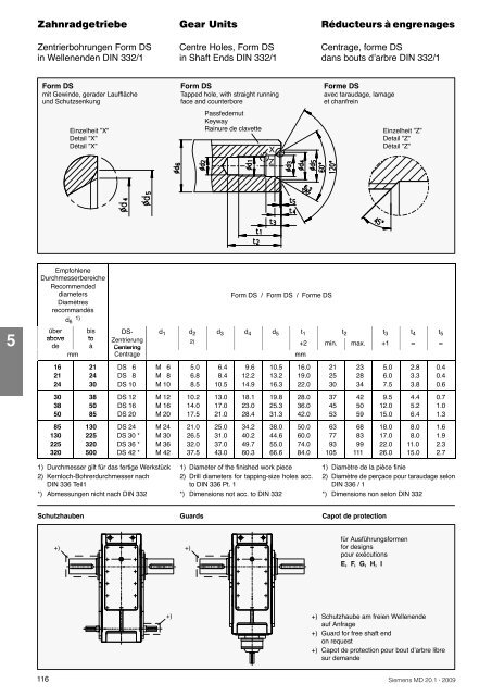
Zentrierbohrungen Form DS Centre Holes, Form DS Centrage, forme DSin Wellenenden DIN 332/1 in Shaft Ends DIN 332/1 dans bouts d’arbre DIN 332/1Form DSmit Gewinde, gerader Laufflächeund SchutzsenkungEinzelheit ”X”Detail ”X”Détail ”X”Form DSTapped hole, with straight runningface and counterborePassfedernutKeywayRainure de clavetteXZForme DSavec taraudage, lamageet chanfreinEinzelheit ”Z”Detail ”Z”Détail ”Z”5EmpfohleneDurchmesserbereicheRecommendeddiametersDiamètresrecommandésd 6 1)überabovedemm16212430385085130225320bistoà212430385085130225320500Form DS / Form DS / Forme DSDS- d 1 d 2 d 3 d 4 d 5 t 1 t 2 t 3 t 4 t 5ZentrierungCentering2) +2 min. max. +1 ≈ ≈CentragemmDS 6DS 8DS 10DS 12DS 16DS 20DS 24DS 30 *DS 36 *DS 42 *M 6M 8M 10M 12M 16M 20M 24M 30M 36M 425.06.88.510.214.017.521.026.532.037.56.48.410.513.017.021.025.031.037.043.09.612.214.918.123.028.434.240.249.760.310.513.216.319.825.331.338.044.655.066.616.019.022.028.036.042.050.060.074.084.02125303745536377931052328344250596883991115.06.07.59.512.015.018.017.022.026.02.83.33.84.45.26.48.08.011.015.00.40.40.60.71.01.31.61.92.32.71) Durchmesser gilt für das fertige Werkstück2) Kernloch-Bohrerdurchmesser nachDIN 336 Teil1*) Abmessungen nicht nach DIN 3321) Diameter of the finished work piece2) Drill diameters for tapping-size holes acc.to DIN 336 Pt. 1*) Dimensions not acc. to DIN 3321) Diamètre de la pièce finie2) Diamètre de perçace pour taraudage selonDIN 336 / 1*) Dimensions non selon DIN 332Schutzhauben Guards Capot de protection+)+)für Ausführungsformenfor designspour exécutionsE, F, G, H, I+)+) Schutzhaube am freien Wellenendeauf Anfrage+) Guard for free shaft endon request+) Capot de protection pour bout d’arbre libresur demande116 ·
Passungsauswahl Selection of ISO Fits Choix des tolérancesPassfedern und Nuten Parallel Keys and Keyways Clavettes parallèles et rainuresPassungsauswahl / Selection of ISO fits / Choix des tolérancesPassungsauswahlSelection of ISO fitsChoix des tolérancesWelle / Shaft / Bouts d’arbresdüberabovedebistojusqu’àWellentoleranzShaft toleranceTolérance des boutsd’arbresBohrungstoleranzBore toleranceTolérance pour lesalésagesmmmmWellentoleranznach Flender-NormShaft toleranceacc. to Flender standardTolérance des bouts d’arbresselon standard Flender25 k625 100 m6 H7100 n6Für außergewöhnliche Betriebsverhältnisse,z.B. Reversierbetrieb unter Last, ist einfesterer Sitz und für die Nabennutbreite dasISO-Toleranzfeld P9 vorzusehen.Seitens des Kunden sind hierzu entsprechendeVorgaben notwendig.For heavy-duty operating conditions, e.g.reversing under load, it is recommended thata tighter fit and for the hub keyway widththe ISO P9 tolerance is selected.In this case, the customer should give therelevant information.Pour des conditions de service exceptionnelles,par exemple service à inversion derotation sous charge, prévoir un serrageplus important et la tolérance ISO P9 pourla largeur b de la rainure dans le moyeu ouun clavetage forcé.Le client doit préciser dans ce cas les informationsrelatives nécessaires.Passfedern / Parallel keys / Clavettes parallèlesMitnehmerverbindung ohne AnzugDrive type fastening without taper actionClavetage libreDurchmesserDiameterDiamètresdüberabovedebistojusqu’àBreiteWidthLargeurb1)HöheHeightHauteurhWellennuttiefeDepth of keywayin shaftProfondeur derainure dansl’arbret 1NabennuttiefeDepth of keywayin hubProfondeur derainure dans lemoyeud + t 2DIN 6885/15Passfederund Nut nachDIN 6885/1Parallel key andkeyway acc.to DIN 6885/1Clavette parallèleet rainure selonDIN 6885 feuille 1mm172230384450586575mm223038445058657585mm6810121416182022mm6788910111214mm3.54555.5677.59mmd + 2.8d + 3.3d + 3.3d + 3.3d + 3.8d + 4.3d + 4.4d + 4.9d + 5.485951109511013025283214161891011d + 5.4d + 6.4d + 7.41) Das Toleranzfeld der Nabennutbreite b für Passfedern ist ISO JS9,bzw. ISO P9 bei erschwerten Betriebsbedingungen.1) The tolerance zone for the hub keyway width b for parallel keys isISO JS9, or ISO P9 for heavy-duty operating conditions.1) La plage de tolérance de la largeur b de la rainure de clavette parrapport à la clavette est ISO JS9, voir ISO P9 en cas de conditionsde fonctionnement difficiles.130150170200230260290330380150170200230260290330380440364045505663708090202225283232364045121315172020222528d + 8.4d + 9.4d + 10.4d + 11.4d + 12.4d + 12.4d + 14.4d + 15.4d + 17.4 · 117
- Page 69 and 70: Ausführungsformen Assemblies Exéc
- Page 71 and 72: Einstufig Single Stage à un trainH
- Page 73 and 74: Zweistufig Two Stage à deux trains
- Page 75 and 76: Zweistufig Two Stage à deux trains
- Page 77 and 78: Dreistufig Three Stage à trois tra
- Page 79 and 80: Dreistufig Three Stage à trois tra
- Page 81 and 82: Vierstufig Four Stage à quatre tra
- Page 83 and 84: Vierstufig Four Stage à quatre tra
- Page 85 and 86: Zweistufig Two Stage à deux trains
- Page 87 and 88: Zweistufig Two Stage à deux trains
- Page 89 and 90: Dreistufig Three Stage à trois tra
- Page 91 and 92: Dreistufig Three Stage à trois tra
- Page 93 and 94: Vierstufig Four Stage à quatre tra
- Page 95 and 96: Vierstufig Four Stage à quatre tra
- Page 97 and 98: Zweistufig Two Stage à deux trains
- Page 99 and 100: Zweistufig Two Stage à deux trains
- Page 101 and 102: Dreistufig Three Stage à trois tra
- Page 103 and 104: Dreistufig Three Stage à trois tra
- Page 105 and 106: Vierstufig Four Stage à quatre tra
- Page 107 and 108: Vierstufig Four Stage à quatre tra
- Page 109 and 110: Zweistufig Two Stage à deux trains
- Page 111 and 112: Zweistufig Two Stage à deux trains
- Page 113 and 114: Dreistufig Three Stage à trois tra
- Page 115 and 116: Dreistufig Three Stage à trois tra
- Page 117 and 118: Vierstufig Four Stage à quatre tra
- Page 119: Vierstufig Four Stage à quatre tra
- Page 123 and 124: Hohlwellen für Hollow Shafts for A
- Page 125 and 126: Hohlwellen für Hollow Shafts for P
- Page 127 and 128: Hohlwelle mit Zahnnabenprofil Hollo
- Page 129 and 130: Gegenflansche für Counterflanges f
- Page 131 and 132: Ölversorgung Oil Supply Alimentati
- Page 133 and 134: Druckschmierung Forced Lubrication
- Page 135 and 136: Druckschmierung Forced Lubrication
- Page 137 and 138: Druckschmierung Forced Lubrication
- Page 139 and 140: Druckschmierung Forced Lubrication
- Page 141 and 142: Wasser-Ölkühler Water-oil Cooler
- Page 143 and 144: Wasser-Ölkühler Water-oil Cooler
- Page 145 and 146: Luft-Ölkühler Air-oil Cooler Refr
- Page 147 and 148: Luft-Ölkühler Air-oil Cooler Refr
- Page 149 and 150: Luft-Ölkühler Air-oil Cooler Refr
- Page 151 and 152: mit Öltemperaturmessung With Therm
- Page 153 and 154: Wellenabdichtungen Shaft Seals Etan
- Page 155 and 156: Anbaumaße für Fitting Dimensions
- Page 157 and 158: Motorlaterne für IEC-Motoren Motor
- Page 159 and 160: Motorlaterne für IEC-Motoren Motor
- Page 161 and 162: Motorlaterne für IEC-Motoren Motor
- Page 163 and 164: Motorlaterne für IEC-Motoren Motor
- Page 165 and 166: Motorlaterne für IEC-Motoren Motor
- Page 167 and 168: Motorlaterne für IEC-Motoren Motor
- Page 169 and 170: Motorlaterne für IEC-Motoren Motor
Zentrierbohrungen Form DS Centre Holes, Form DS Centrage, forme DSin Wellenenden DIN 332/1 in Shaft Ends DIN 332/1 dans bouts d’arbre DIN 332/1Form DSmit Gewinde, gerader Laufflächeund SchutzsenkungEinzelheit ”X”Detail ”X”Détail ”X”Form DSTapped hole, with straight runningface and counterborePassfedernutKeywayRainure de clavetteXZForme DSavec taraudage, lamageet chanfreinEinzelheit ”Z”Detail ”Z”Détail ”Z”5EmpfohleneDurchmesserbereicheRecommendeddiametersDiamètresrecommandésd 6 1)überabovedemm16212430385085130225320bistoà212430385085130225320500Form DS / Form DS / Forme DSDS- d 1 d 2 d 3 d 4 d 5 t 1 t 2 t 3 t 4 t 5ZentrierungCentering2) +2 min. max. +1 ≈ ≈CentragemmDS 6DS 8DS 10DS 12DS 16DS 20DS 24DS 30 *DS 36 *DS 42 *M 6M 8M 10M 12M 16M 20M 24M 30M 36M 425.06.88.510.214.017.521.026.532.037.56.48.410.513.017.021.025.031.037.043.09.612.214.918.123.028.434.240.249.760.310.513.216.319.825.331.338.044.655.066.616.019.022.028.036.042.050.060.074.084.02125303745536377931052328344250596883991115.06.07.59.512.015.018.017.022.026.02.83.33.84.45.26.48.08.011.015.00.40.40.60.71.01.31.61.92.32.71) Durchmesser gilt für das fertige Werkstück2) Kernloch-Bohrerdurchmesser nachDIN 336 Teil1*) Abmessungen nicht nach DIN 3321) Diameter of the finished work piece2) Drill diameters for tapping-size holes acc.to DIN 336 Pt. 1*) Dimensions not acc. to DIN 3321) Diamètre de la pièce finie2) Diamètre de perçace pour taraudage selonDIN 336 / 1*) Dimensions non selon DIN 332Schutzhauben Guards Capot de protection+)+)für Ausführungsformenfor designspour exécutionsE, F, G, H, I+)+) Schutzhaube am freien Wellenendeauf Anfrage+) Guard for free shaft endon request+) Capot de protection pour bout d’arbre libresur demande116 ·


