Create successful ePaper yourself
Turn your PDF publications into a flip-book with our unique Google optimized e-Paper software.
<strong>FLENDER</strong> <strong>gear</strong> <strong>units</strong>ZahnradgetriebeGear UnitsRéducteurs à engrenagesGrößen / Sizes / Tailles 3–22Catalog MD 20.1 • 2009Charakteristische VorzügeCharacteristic FeaturesCharactéristiquesAllgemeine HinweiseGeneral InformationIndications générales12GetriebeauswahlSelection of Gear UnitsSélection de réducteurs3ZahnradgetriebeGear UnitsRéducteur à engrenages4Einzelheiten zu WellenDetails on ShaftsDétails des arbres5ÖlversorgungOil SupplyAlimentation en huile6WellenabdichtungenShaft SealsEtanchéités des arbres7AnbauvariantenAdd-on PiecesVariantes de montage8Explosionsschutz nach ATEX 95Explosion Protection According to ATEX 95Atmosphères explosives selon ATEX 959
Answers for Industry.<strong>Siemens</strong> Industry gibt Antworten auf die Herausforderungenin der Fertigungs-, Prozess- und Gebäudeautomatisierung. UnsereAntriebs- und Automatisierungslösungen auf Basis von TotallyIntegrated Automation (TIA) und Totally Integrated Power (TIP)finden Einsatz in allen Branchen. In der Fertigungs- wie in derProzessindustrie. In Industrie- wie in Zweckbauten.Sie finden bei uns Automatisierungs-,Antriebs- und Niederspannungsschalttechniksowie Industrie-Software vonStandardprodukten bis zu komplettenBranchenlösungen. Mit der Industrie-Softwareoptimieren unsere Kunden aus demproduzierenden Gewerbe ihre gesamteWertschöpfungskette – von Produktdesignund -entwicklung über Produktion undVertrieb bis zum Service. Mit unserenelektrischen und mechanischen Komponentenbieten wir Ihnen integrierteTechnologien für den kompletten Antriebsstrang– von der Kupplung bis zum Getriebe,vom Motor bis zu Steuerungs- undAntriebslösungen für alle Branchen desMaschinenbaus. Mit der TechnologieplattformTIP bieten wir Ihnen durchgän -gige Lösungen für die Energieverteilung.Überzeugen Sie sich selbst von den Möglichkeiten,die Ihnen unsere Automatisierungs-und Antriebslösungen bieten.Und entdecken Sie, wie Sie mit uns IhreWettbewerbsfähigkeit nachhaltig steigernkönnen.1/2 <strong>Siemens</strong> MD 20.1 · 2009
Answers for Industry.<strong>Siemens</strong> Industry answers the challenges in the manufacturingand the process industry as well as in the building automationbusiness. Our drive and automation solutions based on TotallyIntegrated Automation (TIA) and Totally Integrated Power (TIP)are employed in all kinds of industry. In the manufacturing and theprocess industry. In industrial as well as in functional buildings.<strong>Siemens</strong> offers automation, drive, andlow-voltage switching technology as wellas industrial software from standardproducts up to entire industry solutions.The industry software enables our industrycustomers to optimize the entire valuechain – from product design and developmentthrough manufacture and sales upto after-sales service. Our electrical andmechanical components offer integratedtechnologies for the entire drive train –from couplings to <strong>gear</strong> <strong>units</strong>, from motorsto control and drive solutions for allengineering industries. Our technologyplatform TIP offers robust solutions forpower distribution.Check out the opportunities ourautomation and drive solutions provide.And discover how you can sustainablyenhance your competitive edge with us.Des solutions pour l’industrie.<strong>Siemens</strong> Industry propose des solutions pour répondre aux défis detous les secteurs de l’industrie et des équipements techniques dubâtiment. Nos solutions d’entraînement et d’automatisation baséessur Totally Integrated Automation (TIA) et sur Totally IntegratedPower (TIP) trouvent un emploi tant dans l’industrie manufacturièreque dans l’industrie de process, tant dans les bâtiments industrielsque dans les bâtiments tertiaires.Nous vous proposons des matériels d’automatisation,d’entraînement et basse tensionau même titre que des logiciels industriels,des produits standards, et dessolutions sectorielles complètes. Nos logicielsindustriels permettent à nos clients del’industrie productive d’optimiser toute leurchaîne de création de valeur, de l’étude etla conception des produits à leur productionet commercialisation et au serviceaprèsvente. Notre offre de composantsélectri ques et mécaniques intègre des technologiespour constituer une chaîne detrans mission complète: de l’accouplementau réducteur, du moteur à la solution decommande et d’entraînement pour tous lessecteurs de la construction de machines.Notre plateforme technologique TIP met àvotre disposition des solutions complètespour la distribution électrique.Persuadez-vous par vous-même des possibilitésoffertes par nos solutions d‘automatisationet d’entraînement et venez découvrircomment améliorer durablement votrecompétitivité.<strong>Siemens</strong> MD 20.1 · 20091/3
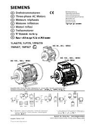
Bauartenübersicht Summary of Basic Types Représentation des typesEinbaulage horizontal / Horizontal mounting position / Position de montage horizontalStirnradgetriebe Helical <strong>gear</strong> <strong>units</strong> Réducteurs à engrenagescylindriquesBauarten H1.., H2.., H3.., H4.. Types H1.., H2.., H3.., H4.. Types H1.., H2.., H3.., H4..1- ... 4-stufig, i N = 1.25 - 450 1- ... 4-stage, i N = 1.25 - 450 1- ... 4 étages, i N = 1.25 - 450H.SH H.HH H.DHH.KH H.FHH.HM, H.DM,H.KM, H.FMKegelstirnradgetriebe Bevel-helical <strong>gear</strong> <strong>units</strong> Réducteurs à engrenagescylindro-coniquesBauarten B2.., B3.., B4.. Types B2.., B3.., B4.. Types B2.., B3.., B4..2- ... 4-stufig, i N = 5 - 400 2- ... 4-stage, i N = 5 - 400 2- ... 4 étages, i N = 5 - 400B.SHB.HH B.DH B.KH B.FH B.HM, B.DM,B.KM, B.FMEinbaulage vertikal / Vertical mounting position / Position de montage verticalStirnradgetriebe Helical <strong>gear</strong> <strong>units</strong> Réducteurs à engrenagescylindriquesBauarten H2.V, H3.V, H4.V Types H2.V, H3.V, H4.V Types H2.V, H3.V, H4.V2- ... 4-stufig, i N = 6.3 - 450 2- ... 4-stage, i N = 6.3 - 450 2- ... 4 étages, i N = 6.3 - 450H.SVH.HVH.DVH.KVH.FVKegelstirnradgetriebe Bevel-helical <strong>gear</strong> <strong>units</strong> Réducteurs à engrenagescylindro-coniquesBauarten B2.V, B3.V, B4.V Types B2.V, B3.V, B4.V Types B2.V, B3.V, B4.V2- ... 4-stufig, i N = 5 - 400 2- ... 4-stage, i N = 5 - 400 2- ... 4 étages, i N = 5 - 400B.SV B.HV B.DVB.KVB.FV2 ·
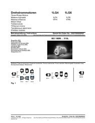
Bauartenübersicht Summary of Basic Types Représentation des typesB 3 S H 1 1Größe / Size / Taille3 ... 22Einbau / Mounting / MontageH = Horizontal / Horizontal / HorizontalM = Ausführung horizontal ohne FußHorizontal design without feetVersion horizontale sans patteV = Vertikal / Vertical / VerticalAusführung Abtriebswelle / Output shaft design / Conception de l’arbre de sortieS = Vollwelle / Solid shaft / Arbre pleinH = Hohlwelle / Hollow shaft / Arbre creuxD = Hohlwelle für SchrumpfscheibeHollow shaft for shrink diskArbre creux pour frette de serrageK = Hohlwelle mit Zahnnabenprofil nach DIN 5480Hollow shaft with involute splines acc. to DIN 5480Arbre creux cannelé selon DIN 5480F = FlanschwelleFlanged shaftArbre à flasqueV = Vollwelle d 2 verstärkt (auf Anfrage)Shaft d 2 reinforced (on request)Arbre d 2 renforcé (sur demande)Stufenanzahl / No. of stages / Nombre de trains1, 2, 3 oder / or / ou 4Bauart / TypeH = Stirnradgetriebe / Helical <strong>gear</strong> <strong>units</strong> / Réducteurs à engrenages cylindriquesB = Kegelstirnradgetriebe / Bevel-helical <strong>gear</strong> <strong>units</strong> / Réducteurs à engrenages cylindro-coniquesWeitere bei Bestellung notwendige Angaben:Übersetzung i, Ausführungen A, B, C, D usw.Further details required in orders:Transmission ratio i, designs A, B, C, D, etc.Autres détails indispensables lors d’une commande:Rapport i, versions A, B, C, D etc.Beispiel B3SH 11Kegelstirnradgetriebe 3-stufig, Ausführung A, i = 16, Abtrieb in Vollwellenausführung,Horizontale Einbaulage, Größe 11Example B3SH 11Bevel-helical <strong>gear</strong> unit, 3-stage, design A, i = 16, solid output shaft design,horizontal mounting position, size 11Exemple B3SH 11Réducteur à engrenages cylindro-coniques à 3 étages, version A, i = 16, version avec arbre de sortie plein,montage horizontal, taille 11 · 3
Inhaltsverzeichnis Contents SommaireInhalt Contents SommaireSeitenPagesCharakteristische Vorzüge Characteristic features Caractéristiques 6Allgemeine Hinweise General information Indications générales 7Getriebeauswahl Selection of <strong>gear</strong> <strong>units</strong> Sélection de réducteursRichtlinie bei konstanter Leistung Guidelines, constant power rating Directives, puissance constante 8 - 9Richtlinie bei variabler Leistung Guidelines, variable power rating Directives, puissance variable 10Erklärung der Bezeichnungen Key to symbols Explication des symboles 11Beispiel Example Exemple 12 - 13Betriebsfaktoren Service factors Facteurs de service 14 - 15Leistungstabellen Tables: Powers and capacities Tableaux de puissanceH1SH H1SH H1SH 16 - 21H2.. H2.. H2.. 22 - 27H3.. H3.. H3.. 28 - 33H4.. H4.. H4.. 34 - 37B2.. B2.. B2.. 38 - 43B3.. B3.. B3.. 44 - 49B4.. B4.. B4.. 50 - 53Ist-Übersetzungen Actual ratios Rapports réels 54 - 57Zulässige radiale Zusatzkräfte Permissible additional radial forces Efforts radiaux exterieurs admissibles 58 - 59Massenträgheitsmomente J 1 Mass moments of inertia J 1 Moments d’inertie de masse J 1 60 - 63Ausführungsformen Assemblies Exécutions 64 - 65Zahnradgetriebe Gear <strong>units</strong> Réducteur à engrenagesH1SH H1SH H1SH 66 - 67H2.H H2.H H2.H 68 - 71H3.H H3.H H3.H 72 - 75H4.H H4.H H4.H 76 - 79B2.H B2.H B2.H 80 - 83B3.H B3.H B3.H 84 - 87B4.H B4.H B4.H 88 - 91H2.V H2.V H2.V 92 - 95H3.V H3.V H3.V 96 - 99H4.V H4.V H4.V 100 - 103B2.V B2.V B2.V 104 - 107B3.V B3.V B3.V 108 - 111B4.V B4.V B4.V 112 - 115Einzelheiten zu Wellen Details on shafts Détails des arbresZentrierbohrungen Centre holes Centrage 116Schutzhauben für Vollwellen Guards for solid shafts Capot de protection pour arbre plein 116Passfedern / Passfedernuten Parallel keys and keyways Clavettes parallèles et rainures 117Hohlwellen für Schrumpfscheiben Hollow shafts for shrink disks Arbre creux pour frette de serrage 118 - 119Hohlwellen für PassfederverbindungenHohlwelle mit Zahnnabenprofilnach DIN 5480Hollow shafts for parallel keyconnectionsHollow shaft with involute splinesacc. to DIN 5480Arbre creux pour raccord de clavette 120 - 121Arbre creux cannelé selon DIN 5480 122 - 123Gegenflansche für Flanschwelle Counterflanges for flanged shafts Conte-bride pour arbre à bride 124 - 1254 ·
Inhaltsverzeichnis Contents SommaireInhalt Contents SommaireSeitenPagesÖlversorgung Oil supply Alimentation en huileÖlauswahl Selection of oil Sélection du type d’huile 126Konservierung Preservation Conservation 126Variantenübersicht Survey of variants Aperçu des variantes 127vertikal: Tauchschmierung Vertical: Dip lubrication vertical: Lubrification par barbotage 128vertikal: DruckschmierungFlanschpumpeVertical: Forced lubricationFlanged-on pumpvertical: Lubrification sous pressionPompe flasquée129 - 130vertikal: DruckschmierungMotorpumpeVertical: Forced lubricationMotor pumpvertical: Lubrification sous pressionMotopompe131vertikal: DruckschmierungÜberwachungsgeräteVertical: Forced lubricationMonitoring instrumentsvertical: Lubrification sous pressionDispositifs de contrôle132horizontal: DruckschmierungHorizontal: Forced lubricationhorizontal: Lubrification souspression133 - 135zusätzliche ÖlkühlungAdditional oil coolerRefroidissement d’huile supplémentaireWasser-Ölkühler Water-oil cooler Refroidisseur d’huile-eau 136 - 139Luft-Ölkühler Air-oil cooler Refroidisseur d’huile-air 140 - 145Heizstäbe Heating elements Cannes de préchauffage 146Öltemperaturmessung Thermometer for oil temperature Mesure de la température de l’huile 147Wellenabdichtungen Shaft seals Etanchéités des arbres 148 - 150Anbauvarianten Mounting variants Variantes de montageMotorlaterne für IEC-Motoren Motor bell housing for IEC motors Lanterne moteur pour moteur IECMotorflansch Motor flange Bride moteur 151mit BIPEX-Kupplung with BIPEX coupling avec accouplement BIPEX 152 - 163mit N-EUPEX-Kupplung with N-EUPEX coupling avec accouplement N-EUPEX 164 - 175Schwingungsdämpfende Drehmomentstützefür GetriebegehäuseVibration reducing torque reactionarm for <strong>gear</strong> housingAmortissement de vibrations parsupports de couple pour cartersde réducteur176 - 177Getriebeschwingen Gear unit swing-bases Châssis supportsmit N-EUPEX-Kupplung with N-EUPEX coupling avec accouplement N-EUPEX 178 - 184mit FLUDEX-Kupplung with FLUDEX coupling avec coupleur FLUDEX 185 - 191Sondereinbaulagen Special mounting positions Positions de montage particulièresEinbaulagen Mounting positions Positions de montage 192Getriebefußleisten Housing base rails Pattes amovibles 193Wasserschneckenausführung Water screw design pour vis de relevage des eaux 194 - 195Motorstuhl Motor bracket Châssis support moteur 196 - 203Gehäuseflansch Housing flange Bride carterKragenflansch Mounting flange - long spacer Bride surélevée 204 - 205Blockflansch Mounting flange - short spacer Bride 206 - 207Explosionsschutz nach ATEX 95Explosion protection accordingto ATEX 95Atmosphères explosivesselon ATEX 95208ZahnradgetriebeTochterprogrammeGear <strong>units</strong>SubrangesRéducteurs à engrenagesprogrammes secondaires209 · 5
1Charakteristische Vorzüge Characteristic Features CaractéristiquesKonstruktion<strong>FLENDER</strong>-Zahnradgetriebe wurden völlig neukonzipiert. Pluspunkte sind: mehr Baugrößen bei weniger Bauteilvarianten, höhere Betriebssicherheit bei gesteigerterLeistungsdichte, überwiegend berührungs- und verschleißfreieLabyrinthdichtungen möglich, Flanschabtriebswellen zur leichteren Getriebemontagebei kleinem Raumbedarf(auf Anfrage).Design<strong>FLENDER</strong> <strong>gear</strong> <strong>units</strong> are a completely newdesign. Advantages are: more sizes with a reduced variety of parts; higher operational reliability combined withincreased power capacity; predominantly non-contacting wear-resistantlabyrinth seals are possible; flanged output shafts to facilitate assemblyof <strong>gear</strong> <strong>units</strong> in confined spaces (on request).ConceptionLes réducteurs à engrenages <strong>FLENDER</strong> ontété totalement repensés. Les avantages quien résultent sont les suivants: une gamme plus large: le nombre decomposant a été réduit, une plus grande sûreté de fonctionnement:la capacité de puissance a été augmentée, une étancheité assurée par des joints labyrinthessans contact et sans usure estpossible le montage des brides d’arbres de sortiesont plus facile (sur demande).Einbaulage<strong>FLENDER</strong>-Zahnradgetriebe sind für horizontaleund vertikale Einbaulage lieferbar.Auch andere Anordnungen sind nach Rücksprachemöglich.Das Grundgetriebe kann durch unterschiedlicheAnbauteile wie z.B. Motorlaternen, Getriebeschwingenoder Rücklaufsperren optimalan die Kundenanforderungen angepasstwerden.Mounting position<strong>FLENDER</strong> <strong>gear</strong> <strong>units</strong> can be supplied for eitherhorizontal or vertical installation.Other arrangements are also possible on request.The basic <strong>gear</strong> unit can be optimally adapted tocustomer requirements by fitting differentadd-on pieces like motor bell housings, <strong>gear</strong>unit swing-bases or backstops.Position de montageLes réducteurs à engrenages <strong>FLENDER</strong> sontlivrables pour un montage en position horizontaleou verticale.Vous pouvez nous consulter pour d’autrespositions de montage: d’autres possibilitésexistent. Les lanternes de moteur, les biellesainsi que les anti-dévireurs sont des équipementsde série.GeräuschverhaltenBei <strong>FLENDER</strong>-Zahnradgetrieben konnte dasGeräuschverhalten entscheidend verbessertwerden. Dazu wurden: die Kegelräder geschliffen, die geräuschdämpfenden Gehäuse mitMASAK-Rechenprogramm entwickelt und außergewöhnlich hohe Überdeckungsgradeder Verzahnung erreicht.Noise behaviourNew concepts were applied to clearly improvethe noise emission of the <strong>gear</strong> <strong>units</strong> by grinding the bevel <strong>gear</strong>s; designing noise-absorbing housings bymeans of the MASAK computing program;and achieving exceptionally large contact ratios.Niveau de bruitLe niveau de bruit des réducteurs à engrenages<strong>FLENDER</strong> pouvait sensiblement êtreamélioré. C’est pourquoi nous avons: rectifié les engrenages coniques, développé l’absorption des carters à l’aidedu programme de calcul MASAK, atteint un rapport de conduite exceptionnel.Temperaturverhalten<strong>FLENDER</strong>-Zahnradgetriebe haben bei einemguten Wirkungsgrad ein günstiges Temperaturverhalten,weil die Gehäuseoberflächen vergrößert wurden, überwiegend berührungsfreie Labyrinthdichtungeneingesetzt werden können und große Lüfter mit einem neu entwickeltenLuftleitsystem zur Anwendung kommen.Bei der Getriebeauswahl legt Flender eineniedrige maximale Öltemperatur zugrunde.Die Betriebssicherheit wird dadurch erhöht,und der Wartungsaufwand verringert sichdurch längere Ölstandszeiten.Thermal conduction<strong>FLENDER</strong> <strong>gear</strong> <strong>units</strong> not only have a highefficiency but also a favourable thermal conduction through enlarged housing surface areas; because non-contacting labyrinth seals canbe used; and because large fans incorporating a newtype of air conduction fan cowl are beingused.The selection of <strong>FLENDER</strong> <strong>gear</strong> <strong>units</strong> is basedon a lower maximum oil temperature. By that,the operational reliability will be increased andthe cost of maintenance reduced due to longeroil change intervals.Résistance à l’échauffementGrâce à leur bon rendement, les réducteurs àengrenages <strong>FLENDER</strong> ont un échauffementminimisé. En effet: les surfaces de carter ont été agrandies, les joints sont libérés de tout frottement, le système de ventilation puissant, nouvellementconçu.Lors du choix du réducteur, Flender définit unetempérature d’huile maximale plus basse. Lasûreté de fonctionnement est ainsi accrue etl’entretien diminué (l’huile dure plus longtemps).Vorratshaltung<strong>FLENDER</strong>-Zahnradgetriebe sind nach einemneuen Baukastensystem konstruiert. Dadurchkonnte die Zahl der Bauteilvarianten reduziertwerden. Die Bauteile sind zum größten Teil aufLager, so dass Flender-Produktionsstättenweltweit kurze Lieferzeiten bieten können.Storing<strong>FLENDER</strong> <strong>gear</strong> <strong>units</strong> have been designedaccording to a new unit construction principle.Through this, the variety of parts could bereduced. The parts are mainly on stock enablingthe Flender manufacturing plants worldwideto deliver at short term.StockageLes réducteurs à engrenages <strong>FLENDER</strong> ontété conçus selon un nouveau système de montageavec des éléments standardisés. C’estainsi que l’on a pu réduire le nombre de composants.Les composants sont pour la plupart enstock, si bien que les centres de productionFlender du monde entier peuvent proposer desdélais de livraison courts.6 ·
Allgemeine Hinweise General Information Indications généralesAchtung!Folgende Punkte sind unbedingt zubeachten! Abbildungen sind beispielhaft undnicht verbindlich. Maßänderungenbleiben vorbehalten.Attention!The following items are absolutely tobe observed! Illustrations are examples only andare not strictly binding. Dimensionsare subject to change.Attention!Les points suivants doivent impérativementêtre respectés! Les schémas sont donnés à titreindicatif, sans engagement. Nousnous réservons le droit de modifierles cotes que nous donnons. Les poids sont des valeursindicatives. L’acheteur s’engage à protéger lespièces rotatives contre tout contactaccidentel. Les consignes de sécuritéen vigueur dans chaque paysd’utilisation doivent être respectées. Avant la mise en service, lire attentivementles instructions de service.Les réducteurs sont livrés finis defabrication mais sans huile. Les quantités d’huile données sontdes valeurs indicatives sansengagement. La quantité d’huileexacte dépend des marques sur lajauge de niveau d’huile. La viscosité de l’huile doit êtreconforme aux indications de laplaque signalétique. Seules les lubrifiants homologuéssont autorisés. Vous trouverez nosmanuels d’utilisation en vigueuravec les tableaux des lubrifiantsrecommandés sur notre site internet:www.flender.com Les réducteurs sont équipés debagues d’étanchéité. D’autres typesd’étanchéité sur demande. Le sens de rotation se détermine ense référant à l’arbre de sortie d 2 . En utilisation exterieure l’expositionau soleil doit être évitée. Leclient doit prévoir les protectionsadéquates.2 Die angegebenen Gewichte sindunverbindliche Mittelwerte. Umlaufende Teile müssen vomKäufer gegen unbeabsichtigtesBerühren geschützt werden.Die gültigen Sicherheitsbestimmungendes jeweiligen Einsatzlandessind zu beachten. Vor Inbetriebnahme ist die Betriebsanleitungzu beachten.Die Getriebe werden betriebsfertig,jedoch ohne Ölfüllung geliefert. Ölmengenangaben sind unverbindlicheRichtwerte.Maßgebend ist die Ölstandsmarkierungam Ölmessstab. The weights are mean values andnot strictly binding. To prevent accidents, all rotatingparts should be guarded accordingto local and national safety regulations. Prior to commissioning, the operatinginstructions must be observed.The <strong>gear</strong> <strong>units</strong> are delivered readyfor operation but without oil filling. Oil quantities given are guide valuesonly. The exact quantity of oildepends on the marks on the oildipstick. Ölviskosität muss den Angabendes Typenschildes entsprechen. The oil viscosity has to correspondto the data given on the name plate. Es dürfen nur freigegebeneSchmierstoffe verwendet werden.Aktuelle Betriebsanleitungen undSchmierstofftabellen finden Sie aufunserer Homepage unter:www.flender.com Die Getriebe werden mit Radialwellendichtringenausgeliefert. AndereDichtungsvarianten auf Anfrage. Drehrichtungsangaben beziehensich auf die Abtriebswelle d 2 . Bei Aufstellung im Freien ist Sonnenbestrahlungzu vermeiden. EntsprechendeSchutzeinrichtungensind kundenseitig vorzusehen. Approved lubricants may be usedonly.You will find current operatinginstructions and lubricant selectiontables on our home page at:www.flender.com The <strong>gear</strong> <strong>units</strong> are supplied withradial shaft seals. Other sealingvariants on request. Directions of rotation referring tooutput shaft d 2 . In case of outdoor installation, insolationis to be avoided. Thecustomer has to provide adequateprotection.Erklärung der Symbole in den Maßzeichnungen:Explanation of symbols used in thedimensioned drawings:Explication des symboles utiliséspour les mesures:= Ölmessstab= Oil dipstick= Jauge de niveau d’huile= Entlüftung= Breather= Purge d’air= Ölablass= Oil drain= Vidange d’huile= ÖleinfüllungAb Getriebegröße 13 Druckschraubenim Gehäusefuß und Ausrichtflächenauf dem Oberteil des Gehäuses.Fußschrauben mit Mindest-Festigkeitsklasse8.8. Toleranz der Befestigungsbohrungenim Gehäuse nachDIN EN 20273 – Reihe ”grob”.Die Getriebe sind konserviert und imFarbton RAL 5015 lackiert.= Oil fillerFrom size 13 up jack screws in thehousing feet, and leveling pads on theupper housing part.Foundation bolts of min. propertyclass 8.8. Tolerance of the clearanceholes in the housing acc. to DIN EN20273 – ”coarse” series.The <strong>gear</strong> housings are protectedagainst corrosion and sprayed in RAL5015.= Tubulure de versementd’huileA partir de la taille 13, des vis deserrage sont prévues dans les piedsdu carter et des faces de référencessont prévues sur la partie supérieuredu carter.Vis de fixation en classe min. 8.8.Tolérance des alésages de fixationdans le carter selon DIN EN 20273 –série ”gros”.Leurs carters reçoivent un traitementanti-corrosion et sont peints en RAL 5015. · 7
Richtlinien für die Auswahl Guidelines for the Selection Directives de sélectionKonstante Leistung Constant Mechanical Power Puissance constantemechanisch Rating mécanique1. Bestimmung von Getriebebauartund GrößeDetermination of <strong>gear</strong> unittype and sizeDétermination du type et dela taille du réducteur1.1 Bestimmung der ÜbersetzungFind the transmission ratioDétermination du rapporti s =n 1n 21.2 Bestimmung der GetriebenennleistungDetermine nominal power rating of the <strong>gear</strong> unitDétermination de la puissance nominale du réducteur3P 2N ≥ P 2 x f 1 x f 2Rücksprache nicht erforderlich, wenn:It is not necessary to consult us, if:Demande n’est pas nécessaire si:3.33 x P 2 ≥ P 2N1.3 Kontrolle auf Maximalmoment z.B.: Betriebsspitzen-, Anfahr- oder BremsmomentCheck for maximum torque, e. g. peak operating-, starting- or braking torqueContrôle du couple maximal, par ex.: pointes de fonctionnement, couple de démarrageou de freinageP 2N ≥ T A x n 19550x f 3Getriebegrößen und Stufenanzahl sind in den Leistungstabellen abhängig von i N und P 2NfestgelegtGear unit sizes and number of reduction stages are given in rating tables depending on i N and P 2NLes tailles des réducteurs et le nombre d’étages donnés dans les tableaux de puissancedépendent de i N et de P 2N1.4 Prüfung der Zulässigkeit von Zusatzkräften auf die Abtriebswelle; siehe Seiten 58 und 59Check whether additional forces on the output shaft are permissible; see pages 58 and 59Vérification des efforts supplémentaires admissibles sur l’arbre de sortie; pages 58 et 591.5 Prüfung, ob Ist-Übersetzung i geeignet ist, siehe Seiten 54 - 57Check whether the actual ratio i as per tables on pages 54 - 57 is acceptablePour vérifier si le rapport réel est approprié, se reporter aux tableaux des pages 54 - 57Einbaulage / Mounting position / Position de montage2. Bestimmung der ÖlversorgungDetermination of oil supplyDétermination de lubrificationHorizontal / Horizontal / HorizontaleAlle zu schmierenden Elemente liegen im Ölbzw. werden mit Spritzöl versorgtDruckschmierung auf AnfrageAll parts to be lubricated are lying in the oil orare splash lubricatedForced lubrication on requestToutes les parties à lubrifier baignent dansl’huile ou sont lubrifiées par barbotageLubrification par pression sur demandeVertikal / Vertical / VerticaleMögliche Ölversorgungsvarianten:– Tauchschmierung– Druckschmierung mittels Flansch- oderMotorpumpeVorzugsvarianten und Auswahlkriterien sieheSeiten 126 - 147Possible oil supply variations:– Dip lubrication– Forced lubrication by means of flanged-onpump or motor pumpFor preferred variants and criteria for selection,see pages 126 - 147Type de lubrification possible:– Lubrification par barbotage– Lubrification forcée par pompe attelée ougroupe motopompeVariantes et critères de sélection,voir pages 126 - 1478 ·
Richtlinien für die Auswahl Guidelines for the Selection Directives de sélectionKonstante Leistung Thermal Capacities Puissance constantethermischthermique3. Bestimmung der erforderlichen WärmegrenzleistungenP GNotwendige Daten: Bauart Größe Nennübersetzung Umgebungstemperatur Antriebsdrehzahl(1000 / 1200 / 1500 / 1800 min -1 ) Getriebe mit TauchschmierungFür die nachfolgende Rechnung geltenfolgende Annahmen: Einschaltdauer: 100 % Aufstellung in großer Halle (Windgeschwindigkeit>= 1,4 m/s), Höhenlage bis 1000 m Getriebe mit Mineralöl ISO-VG4603. Determination of required thermal capacityP GData required: Type Size Nominal ratio Ambient temperature Input speed(1000 / 1200 / 1500 / 1800 min -1 ) Gear unit with dip lubricationFor the calculation below the following hasbeen assumed: Operating cycle: 100 % Installation in a large hall (wind velocity >=1.4 m/s), altitude up to 1000 m Gear unit with mineral oil ISO-VG460Annahmen passend zu Einsatzbedingungen / Assumptions corresponding tooperating conditions / Les hypothèses correspondent aux conditions d’utilisation3. Détermination de la capacité thermiquenécessaire P GDonnées nécessaires: Type Taille Rapport nominal Température ambiante Vitesse d’entrée(1000 / 1200 / 1500 / 1800 min -1 ) Réducteurs avec lubrification par barbootageLes hypothèses suivantes sont prises en considérationpour le calcul: Durée d’utilisation: 100 % Implantation dans un grand hall (Vitesse duvent >= 1,4 m/s), Altitude jusqu’à 1000 m Réducteurs avec huile minérale ISO-VG4603Annahmen abweichendvon EinsatzbedingungenAssumptions deviatingfrom operatingconditionsLes hypothèsess’écartent des conditionsd’utilisations1) ohne Zusatzkühlung / without auxiliary cooling / sans refroidissementP G = P GA * f 4 * f 8 P GA = ....... (siehe Seiten / see pages / voir pages 18 - 53)P G = .........f 4 = ....... f 8 = .......P G < P 2 : Zusatzkühlung erforderlich / auxiliary cooling requiredrefroidissement auxiliaire nécessaire2) Lüfter / fan / ventilateur3) Kühlschlange / cooling coil / serpentinP G >= P 24) Lüfter und Kühlschlange / fan and cooling coil / ventilateur et serpentin5) Wasser- / Luft-Ölkühler / water- / air-oil cooler / radiateur eau / air-huile2) Lüftereinsatz möglich / Fan possible / Montage ventilateur possibleP G = P GB * f 4 * f 8 P GB = ....... (siehe Seiten / see pages / voir pages 18 - 53)P G = .........f 4 = ....... f 8 = .......P G < P 2 : Zusatzkühlung erforderlich / auxiliary cooling requiredrefroidissement auxiliaire nécessaire3) Kühlschlange / cooling coil / serpentinP G >= P 24) Lüfter und Kühlschlange / fan and cooling coil / ventilateur et serpentin5) Wasser- / Luft-Ölkühler / water- / air-oil cooler / radiateur eau / air-huile3) Einsatz Kühlschlange möglich / Cooling coil possibleMontage serpentin possibleP G = P GC * f 5 * f 8 P GC = ....... (siehe Seiten / see pages / voir pages 18 - 53) *)P G = .........f 5 = ....... f 8 = .......P G < P 2 : Zusatzkühlung erforderlich / auxiliary cooling requiredrefroidissement auxiliaire nécessaire4) Lüfter und Kühlschlange / fan and cooling coil / ventilateur et serpentinP G >= P 25) Wasser- / Luft-Ölkühler / water- / air-oil cooler / radiateur eau / air-huile4) Einsatz Lüfter und Kühlschlange möglich / Fan and cooling coil possibleMontage ventilateur et serpentin possibleP G = P GD * f 5 * f 8 P GD = ....... (siehe Seiten / see pages / voir pages 18 - 53) *)P G = .........f 5 = ........ f 8 = .......P G < P 2 : Zusatzkühlung erforderlich / auxiliary cooling requiredrefroidissement auxiliaire nécessaireP G >= P 25) Wasser- / Luft-Ölkühler / water- / air-oil cooler / radiateur eau / air-huileGetriebe ohne ZusatzkühlungausreichendGear unit without auxiliarycooling is sufficientRéducteur sans systèmede refroidissementcomplémentaireest suffisantGetriebe mit LüfterkühlungausreichendGear unit with fanis sufficientRéducteur avec ventilateurest suffisantGetriebe mit KühlschlangeausreichendGear unit with coolingcoil is sufficientRéducteur avec serpentinest suffisantGetriebe mit Lüfterund KühlschlangeausreichendGear unit with fan andcooling coil is sufficientRéducteur avec ventilateuret serpentin estsuffisantNachrechnung mittels Variation der obengenannten Annahmen: <strong>FLENDER</strong> CD-ROM x.CAT P G >= P 2Recalculation with other assumptions:Recalculation avec d’autres hypothèses: www.flender.com P G < P 2Getriebe mit gewählter Kühlung ausreichendGear unit with selected cooling is sufficientRéducteur avec refroidissement est suffisantRücksprache mit Flender notwendig!Variationsmöglichkeiten für folgendeDaten: Ölsorte / Ölviskosität / Ölstand Fundament- oder Aufsteckgetriebe Einsatz einer ÖlkühlanlageConsult Flender!Variation of the following items ispossible: Oil grade / viscosity / level Gear unit on foundation or shaftmounted<strong>gear</strong> unit Application of an oil supply systemVeuillez contacter Flender!Possibilité de modification desdonnées suivantes: Type / viscosite / niveau de l’huile Réducteur sur fondation ou flottant Adjonction d’une centrale derefroidissement*) Werte gelten für eine Kühlwassereintrittstemperaturvon20 °C*) Values refer to a cooling waterinlet temperature of 20 °C*) Les valeurs sont valablespour une température d’eaude refroidissement de 20 °CDie Art der gegebenenfalls notwendigen Zusatzkühlungist von den Einsatzbedingungen beim Kunden(Staubbelastung, Kühlwasseranschluß usw.)abhängig.The type of the possibly required additional coolingis dependent on the operating conditions at thecustomer’s (dust, cooling water connection, etc.)Le type du système de refroidissement eventuellementnécessaire dépendant des conditionsd’utilisation par le client (taux de poussière, connexiond’eau etc.) · 9
Richtlinien für die Auswahl Guidelines for the Selection Directives de sélectionVariable Leistung Variable Power Rating Puissance variableFür Arbeitsmaschinen mit konstanten Drehzahlenund variablen Leistungen kann dasGetriebe nach der sogenannten äquivalentenLeistung ausgelegt werden. Dabei wirdein Arbeitszyklus zugrunde gelegt, dessenPhasen I, II...n die Leistungen P I , P II ...P nerfordern, wobei die jeweiligen Leistungenden prozentualen Zeitanteil X I , X II ...X n haben.Mit diesen Angaben wird die äquivalenteLeistung nach folgender Formel berechnet:For driven machines with constant speedsand variable power ratings the <strong>gear</strong> unit canbe designed according to the equivalentpower rating. For this, a working cycle wherephases I, II...n require power P I , P II ...P n andthe respective power ratings operate fortime fractions X I , X II ...X n is taken as a basis.The equivalent power rating can be calculatedfrom these specifications with thefollowing formula:En présence de machines entraînées à unevitesse constante mais avec des puissancesvariables, nous pouvons sélectionner leréducteur en fonction de la puissance équivalente.En pareil cas nous partons d’un cyclede charge dont les phases I, II...n exigent lespuissances P I , P II ...P n, chaque puissanceayant une tranche de temps X I , X II ...X n expriméeen %. En vertu de ces indications, nouscalculons la puissance à l’aide de la formulesuivante:36.6P 2äq P 6.6I X I100 P 6.6II X II100 P 6.6n X n100Die Bestimmung der Getriebegröße erfolgtdann analog den Punkten 1.1 ... 1.5 und 3.Dabei gilt:The size of the <strong>gear</strong> unit can then be determinedanalogously to points 1.1 ... 1.5 and 3.as follows:Nous déterminons ensuite la taille du réducteurde manière analogue au contenu dessection 1.1 à 1.5 et 3. Ce faisant, noustenons compte de la formule suivante:P 2N ≥ P 2äq f 1 f 2Anschließend, nachdem P 2N bestimmt wurde,sind die Leistungs- und Zeitanteile nachfolgenden Bedingungen zu prüfen.1) Die einzelnen Leistungsanteile P I , P II ...P nmüssen größer 0,4 x P 2N sein.2) Die einzelnen Leistungsanteile P I , P II ...P ndürfen 1,4 x P 2N nicht überschreiten.3) Bei den Leistungsanteilen P I , P II ...P n ,die größer als P 2N sind, darf die Summeder Zeitanteile X I , X II ... X n maximal 10%betragen.Falls eine der drei Bedingungen nicht erfülltwird, so ist eine erneute Berechnung von P 2äqnotwendig.Grundsätzlich ist zu berücksichtigen, dasseine kurzzeitige Spitzenleistung, die nichtbei der Ermittlung von P 2äq erfasst wird, nichtgrößer als P max = 2 x P 2N sein darf.Then, when P 2N has been determined, thepower and time fractions must be checkedby applying the following requirements:1) The individual power fractions P I , P II ...P nmust be greater than 0.4 x P 2N .2) The individual power fractions P I , P II ...P nmust not exceed 1.4 x P 2N .3) If power fractions P I , P II ...P n are greaterthan P 2N , the sum of time fractions X I ,X II ...X n must not exceed 10%.If any one of the three requirements is notmet, P 2äq must be recalculated.It must be borne in mind that a brief peakpower rating not included in the calculationof P 2äq must not be greater than P max = 2 xP 2N .Ensuite, une fois P 2N déterminé, il faut vérifierles tranches de puissance et de tempsen fonction des conditions suivantes:1) Les différentes tranches de puissance P I ,P II ...P n doivent être supérieures à 0,4 x P 2N .2) Les différentes tranches de puissance P I ,P II ...P n ne doivent pas dépasser 1,4 x P 2N .3) Lorque les tranches de puissance P I ,P II ...P n sont supérieures à P 2N , la sommede tranches de temps X I , X II ...X n ne doitpas dépasser 10%.Si l’une des trois conditions susmentionnéesn’est pas satisfaite, il faut recalculer P 2äq .Se rappeler d’une manière fondamentalequ’une brève crête de puissance non priseen compte lors de la détermination de P 2äqne doit pas dépasser P max = 2 x P 2N .In Einsatzfällen mit variablen Drehmomentenaber konstanter Drehzahl erfolgt dieGetriebeauslegung auf der Basis des sogenanntenäquivalenten Drehmomentes.Für bestimmte Anwendungen kann einezeitfeste Auslegung des Getriebes ausreichendsein. Dazu gehören zum Beispiel sporadischerEinsatz (Schleusenantriebe) odergeringe Abtriebsdrehzahlen(n 2 4 min -1 ).In applications where the torque is variablebut the speed constant the <strong>gear</strong> unit canbe designed on the basis of the so-calledequivalent torque.A <strong>gear</strong> unit design which is finite-life fatigue-resistantcan be sufficient for certainapplications, for example, sporadic operation(lock-gate drives) or low output speeds(n 2 4 min -1 ).Dans les cas d’application présentant descouples variables mais à vitesse constante,le réducteur est calculé sur la base du coupleéquivalent.Dans certaines applications, il pourra suffireque le réducteur soid conçu résistant pendantune période déterminée. Parmi ellesfigurent les uti-lisations sporadiques (fonctionnementdes écluses) ou celles à faiblesvitesse de sortie (n 2 4 min -1 ).Beispiel:LastkollektivExample:Service classificationExemple:Collectif de charges10 ·
Erklärung der Bezeichnungen Key to Symbols Explication des symbolesErklärung der Bezeichnungen:Key to symbols:Explication des symboles:E D = Einschaltdauer in %(z.B. E D = 80% je Stunde)E D = Operating cycle per hour in %,e.g. E D = 80% / hE D = Durée d’utilisation en %, par ex:(E D = 80% par heure)f 1 = Arbeitsmaschinenfaktor(Tabelle 1), Seite 14f 1 = Factor for driven machine(table 1), page 14f 1 = Facteur de travail des machines(tableau 1), page 14f 2 = Antriebsmaschinenfaktor(Tabelle 2), Seite 15f 2 = Factor for prime mover(table 2), page 15f 2 = Facteur des machines motrices(tableau 2), page 15f 3 = Spitzenmomentfaktor(Tabelle 3), Seite 15f 3 = Peak torque factor(table 3), page 15f 3 = Facteur des pointes maximales(tableau 3), page 15f 4 = Wärmefaktoren(Tabelle 4), Seite 15f 5 = Wärmefaktoren(Tabelle 5), Seite 15f 4 = Thermal factors(table 4), page 15f 5 = Thermal factors(table 5), page 15f 4 = Facteurs thermiques(tableau 4), page 15f 5 = Facteurs thermiques(tableau 5), page 153f 8 = Ölversorgungsfaktor bei Vertikalgetrieben,(Tabelle 8), Seite 15.Bei Horizontalgetrieben: f 8 = 1i = Ist-Übersetzungf 8 = Oil supply factor for vertical <strong>gear</strong><strong>units</strong>(table 8), page 15.For horizontal <strong>gear</strong> <strong>units</strong>: f 8 = 1i = Actual ratiof 8 = Facteur d’alimentation en huile pourles rereducteurs verticaux (tableau8), page 15. Pour les reducteurshorizontaux: f 8 = 1i = Rapport réeli N = Nennübersetzungi N = Nominal ratioi N = Rapport nominali s = Soll-Übersetzungi s = Required ratioi s = Rapport théoriquen 1 = Antriebsdrehzahl (min -1 )n 1 = Input speed (min -1 )n 1 = Vitesse d’entrée (min -1 )n 2 = Abtriebsdrehzahl (min -1 )n 2 = Output speed (min -1 )n 2 = Vitesse de sortie (min -1 )P G = Erforderliche WärmegrenzleistungP G = Required thermal capacityP G = Capacité thermique nécessaireP GA = Wärmegrenzleistung für Getriebeohne Zusatzkühlung,Seiten 18 - 53P GA = Thermal capacity for <strong>gear</strong> <strong>units</strong>without auxiliary cooling,pages 18 - 53P GA = Capacité thermique limite sanssystème de refroidissement complémentaire,pages 18 - 53P GB = Wärmegrenzleistung für Getriebemit Lüfterkühlung,Seiten 18 - 53P GB = Thermal capacity for <strong>gear</strong> <strong>units</strong> withfan cooling,pages 18 - 53P GB Capacité thermique limite pourréducteurs avec refroidissementpar ventilateur, pages 18 - 53P GC = Wärmegrenzleistung für Getriebemit eingebauter Kühlschlange,Seiten 18 - 53P GC = Thermal capacity for <strong>gear</strong> <strong>units</strong> withbuilt-in cooling coil,pages 18 - 53P GC = Capacité thermique limite pourréducteurs avec serpentin de refroidissement,pages 18 - 53P GD = Wärmegrenzleistung für Getriebemit eingebauter Kühlschlange undLüfter, Seiten 18 - 53P GD = Thermal capacity for <strong>gear</strong> <strong>units</strong> withbuilt-in cooling coil and fan,pages 18 - 53P GD = Capacité thermique limite avec serpentinde refroidissement intégréet ventilateur, pages 18 - 53P 2N = Getriebenennleistung (kW),siehe LeistungstabellenSeiten 16 - 50P 2N = Nominal power rating of <strong>gear</strong> unit(kW), see rating tables,pages 16 - 50P 2N = Puissance nominale du réducteur(kW); voir tableau de puissance,pages 16 - 50P 2 = Leistung der Arbeitsmaschine (kW)P 2 = Power rating of driven machine (kW)P 2 = Puissance de la machine de travail(kW)t = Umgebungstemperatur (°C )t = Ambient temperature (°C )t = Température ambiante (°C )T A = Max. auftretendes Drehmomentan Eingangswelle z.B.: Betriebsspitzen-,Anfahr- oder Bremsmoment(Nm)T A = Max. torque occurring on inputshaft, e.g. peak operating-, startingorbraking torque (Nm)T A = Couple maximal à l’arbre d’entrée;par ex: pointes de fonctionnement,couple de freinage ou de démarrage(Nm)T 2N = Nenn-Abtriebsdrehmoment (kNm),Seiten 17 - 51T 2N = Nominal output torque (kNm),pages 17 - 51T 2N = Couple nominal de sortie (kNm),pages 17 - 51P 2äq = äquivalente Leistung (kW)P 2äq = Equivalent power rating (kW)P 2äq = Puissance équivalente (kW)P I , P II , P n= Leistungsanteile (kW) aus LastkollektivP I , P II , P n= Fractions of power rating (kW) obtainedfrom service classificationP I , P II , P n= Tranches de puissance (kW) d’uncollectif de chargesX I , X II , X n= Zeitanteile (%) aus Lastkollektiv · X I , X II , X n= Fractions of time (%) obtained fromservice classificationX I , X II , X n= Tranches de temps (%) d’un collectifde charges11
Richtlinien für die Auswahl Guidelines for the Selection Directives de sélectionBerechnungsbeispiel Calculation Example Exemple de calculmechanisch Mechanical Power Rating mécaniqueGegeben:Known criteria:Données:ANTRIEBSMASCHINEElektromotor:P 1 =75 kWMotordrehzahl: n 1 = 1500 min -1Max. Anfahrmoment: T A = 720 NmPRIME MOVERElectric motor: P 1 = 75 kWMotor speed: n 1 = 1500 min -1Max. starting torque: T A = 720 NmMACHINE MOTRICEMoteur électrique: P 1 = 75 kWVitesse du moteur: n 1 = 1500 min -1Couple dedémarrage max.: T A = 720 Nm3ARBEITSMASCHINEGurtbandförderer: P 2 = 66 kWDrehzahl: n 2 = 26 min -1Betriebsdauer: 12 h / TagAnläufe je Stunde: 7Einschaltdauerje Stunde: E D = 100%Umgebungstemperatur: 30 °CAufstellung ingroßer Halle:Windgeschwindigkeit>= 1,4 m/sHöhenlage:MeereshöheDRIVEN MACHINEBelt conveyor: P 2 = 66 kWSpeed: n 2 = 26 min -1Duty:12 h / dayStarts per hour: 7Operating cycleper hour: E D = 100%Ambienttemperature: 30 °CInstallation in alarge hall:wind velocity>= 1.4 m/sAltitude:sea levelMACHINE DE TRAVAILTransporteur à bandes: P 2 = 66 kWVitesse: n 2 = 26 min -1Durée de fonctionnement: 12 h / jourNombre de démarragespar heure: 7Durée d’utilisationhoraire: E D = 100%Températureambiante: 30 °CInstallation dans ungrande hall:vitesse du vent>= 1,4 m/sAltitude:niveau de la merGETRIEBEAUSFÜHRUNGKegelstirnradgetriebeEinbau:horizontalAbtriebswelle d 2 : rechts, AusführungC, VollwelleDrehrichtung derAbtriebswelle d 2 : linksGEAR UNIT DESIGNBevel-helical <strong>gear</strong> unitMounting position:Output shaft d 2 :Direction of rotationof output shaft d 2 :horizontalon right hand sidedesign C, solid shaftccwVERSION DU REDUCTEURRéducteur à engrenages cylindro-coniquesMontage:horizontalArbre de sortie d 2 : droite, ExécutionC, arbre pleinSens de rotation del’arbre de sortie d 2 : gaucheGesucht:Getriebebauart, Getriebegröße1. Bestimmung der Getriebebauart undGröße1.1 Bestimmung der ÜbersetzungRequired:Type and size of <strong>gear</strong> unit1. Selection of <strong>gear</strong> unit type and size1.1 Calculation of transmission ratioOn cherche:La taille et le type du réducteur1. Détermination de la taille et du typedu réducteur1.1 Détermination du rapporti s =n 1n 2=150026= 57.7 i N = 561.2 Bestimmung der Getriebenennleistung 1.2 Determination of the <strong>gear</strong> unit nominalpower rating1.2 Détermination de la puissance nominaledu réducteurP 2N ≥ P 2 x f 1 x f 2 = 66 x 1.3 x 1 = 85.8 kWAus Leistungstabelle Bauart B3SH, Getriebegröße9 mit P 2N = 100 kW gewählt.Selected from power rating table: type B3SH,<strong>gear</strong> unit size 9, with P 2N = 100 kWSélectionné sur le tableau de puissance: typeB3SH, taille 9 avec P 2N = 100 kW3.33 x P 2 ≥ P 2N 3.33 x 66 = 219.8 kW > P 2N It is not necessary to consult usRücksprache nicht erforderlichIl n’est pas nécessaire de nous consulter1.3 Kontrolle auf Anfahrmoment 1.3 Checking the starting torque 1.3 Contrôle du couple de démarrageP 2N ≥ T A x n 19550x f 3 =720 x 15009550x 0.65 = 73.5 kWP 2N = 100 kW > 73.5 kW2. Bestimmung der Ölversorgung2. Determination of oil supply2. Détermination de lubrificationGetriebe mit TauchschmierungGear unit with dip lubicationRéducteur avec lubrification par barbotage12 ·
Richtlinien für die Auswahl Guidelines for the Selection Directives de sélectionBerechnungsbeispiel Calculation Example Exemple de calculthermisch Thermal Capacity thermique3. Bestimmung der erforderlichen WärmegrenzleistungenP GNotwendige Daten: Bauart: B3SH Größe: 09 Nennübersetzung: i N = 56 Umgebungstemperatur: t = 30 C Antriebsdrehzahl: n 1 = 1500 min -1 Getriebe mit TauchschmierungFür die nachfolgende Rechnung geltenfolgende Annahmen: Einschaltdauer: 100 % Aufstellung in großer Halle (Windgeschwindigkeit>= 1,4 m/s), Höhenlage bis 1000 m Getriebe mit Mineralöl ISO-VG4603. Determination of required thermal capacityP GData required: Type: B3SH Size: 09 Nominal ratio: i N = 56 Ambient temperature: t = 30 C Input speed: n 1 = 1500 min -1 Gear unit with dip lubricationFor the calculation below the following hasbeen assumed: Operating cycle: 100 % Installation in a large hall (wind velocity >=1.4 m/s), altitude up to 1000 m Gear unit with mineral oil ISO-VG460Annahmen passend zu Einsatzbedingungen / Assumptions corresponding tooperating conditions / Les hypothèses correspondent aux conditions d’utilisation3. Détermination de la capacité thermiquenécessaire P GDonnées nécessaires: Type: B3SH Taille: 09 Rapport nominal: i N = 56 Température ambiante: t = 30 C Vitesse d’entrée: n 1 = 1500 min -1 Réducteurs avec lubrification par barbootageLes hypothèses suivantes sont prises en considérationpour le calcul: Durée d’utilisation: 100 % Implantation dans un grand hall (Vitesse duvent >= 1,4 m/s) Altitude jusqu’à 1000 m Réducteurs avec huile minérale ISO-VG4603Annahmen abweichendvon EinsatzbedingungenAssumptions deviatingfrom operatingconditionsLes hypothèsess’écartent des conditionsd’utilisations1) ohne Zusatzkühlung / without auxiliary cooling / sans refroidissementP G = P GA * f 4 * f 8 P GA = 64.8 kW (siehe Seite / see page / voir page 48)P G = 57 kWf 4 = 0.88 f 8 = 1.0P G < P 2 : Zusatzkühlung erforderlich / auxiliary cooling requiredrefroidissement auxiliaire nécessaire2) Lüfter / fan / ventilateur3) Kühlschlange / cooling coil / serpentin4) Lüfter und Kühlschlange / fan and cooling coil / ventilateur et serpentin5) Wasser- / Luft-Ölkühler / water- / air-oil cooler / radiateur eau / air-huile2) Lüftereinsatz möglich / Fan possible / Montage ventilateur possibleP G = P GB * f 4 * f 8 P GB = 140 kW (siehe Seite / see page / voir page 48)P G = 123.2 kWf 4 = 0.88 f 8 = 1.0P G < P 2 : Zusatzkühlung erforderlich / auxiliary cooling requiredrefroidissement auxiliaire nécessaire3) Kühlschlange / cooling coil / serpentinP G >= P 24) Lüfter und Kühlschlange / fan and cooling coil / ventilateur et serpentin5) Wasser- / Luft-Ölkühler / water- / air-oil cooler / radiateur eau / air-huile3) Einsatz Kühlschlange möglich / Cooling coil possibleMontage serpentin possibleP G = P GC * f 5 * f 8 P GC = 174 kW (siehe Seite / see page / voir page 48) *)P G = 161.8 kWf 5 = 0.93 f 8 = 1.0P G < P 2 : Zusatzkühlung erforderlich / auxiliary cooling requiredrefroidissement auxiliaire nécessaire4) Lüfter und Kühlschlange / fan and cooling coil / ventilateur et serpentinP G >= P 25) Wasser- / Luft-Ölkühler / water- / air-oil cooler / radiateur eau / air-huile4) Einsatz Lüfter und Kühlschlange möglich / Fan and cooling coil possibleMontage ventilateur et serpentin possibleP G = P GD * f 5 * f 8 P GD = 241 kW (siehe Seite / see page / voir page 48) *)P G = 224.1 kWf 5 = 0.93 f 8 = 1.0P G < P 2 : Zusatzkühlung erforderlich / auxiliary cooling requiredrefroidissement auxiliaire nécessaireP G >= P 25) Wasser- / Luft-Ölkühler / water- / air-oil cooler / radiateur eau / air-huileGetriebe mit ZusatzkühlungnotwendigGear unit with auxiliarycooling requiredRéducteur devant êtrerefroidi par systèmede refroidissementcomplémentaireGetriebe mit LüfterkühlungausreichendGear unit with fanis sufficientRéducteur avec ventilateurest suffisantGetriebe mit KühlschlangeausreichendGear unit with coolingcoil is sufficientRéducteur avec serpentinest suffisantGetriebe mit Lüfterund KühlschlangeausreichendGear unit with fan andcooling coil is sufficientRéducteur avec ventilateuret serpentin estsuffisantNachrechnung mittels Variation der obengenannten Annahmen:Recalculation with other assumptions:Recalculation avec d’autres hypothèses: <strong>FLENDER</strong> CD-ROM x.CATwww.flender.comP G >= P 2P G < P 2Getriebe mit gewählter Kühlung ausreichendGear unit with selected cooling is sufficientRéducteur avec refroidissement est suffisantRücksprache mit Flender notwendig!Variationsmöglichkeiten für folgendeDaten: Ölsorte / Ölviskosität / Ölstand Fundament- oder Aufsteckgetriebe Einsatz einer ÖlkühlanlageConsult Flender!Variation of the following items ispossible: Oil grade / viscosity / level Gear unit on foundation or shaftmounted<strong>gear</strong> unit Application of an oil supply systemVeuillez contacter Flender!Possibilité de modification desdonnées suivantes: Type / viscosite / niveau de l’huile Réducteur sur fondation ou flottant Adjonction d’une centrale derefroidissement*) Werte gelten für eine Kühlwassereintrittstemperaturvon20 °C*) Values refer to a cooling waterinlet temperature of 20 °C*) Les valeurs sont valablespour une température d’eaude refroidissement de 20 °CDas gewählte Getriebe B3SH 09 mit i N = 56 istmit einer geeigneten Zusatzkühlung auszurüsten.Je nach Einsatzbedingungen beim Kunden istmindestens ein Lüfter oder eine Kühlschlangevorzusehen. · For the selected <strong>gear</strong> unit B3SH 09 with i N = 56suitable auxiliary cooling is to be provided. Dependenton the operating conditions at the customer’s, atleast a fan or a cooling coil is to be provided.Le réducteur choisi B3SH 09 avec i N = 56 doitêtre équipé d’un refroidissement additionnelapproprié. Selon les conditions d’installation leclient doit prévoir au minimum un ventilateur ouun serpentin.13
Betriebsfaktoren Service Factors Facteurs de serviceTabelle 1 Arbeitsmaschinenfaktor f 1 / Table 1 Factor for driven machines f 1 / Tableau 1 Facteur des machines entraînées f 13AbwasserEindicker (Zentralantrieb)FilterpressenFlockungsrührerKreiselbelüfterRechenanlagenRund- und LängsräumerVoreindickerWasserschneckenpumpenWasserturbinenPumpenKreiselpumpenVerdrängerpumpen1 Kolben> 1 KolbenBaggerEimerkettenKippwerkeRaupenfahrzeugeSchaufelräderals Aufnehmerfür UrmaterialSchneidköpfeSchwenkwerke ∗Blechbiegemaschinen∗ChemischeIndustrieExtruderGummikneterGummikalanderKühltrommelnMischer fürgleichmäßiges GutungleichmäßigesGutRührwerke fürRührgut mitgleichmäßigerDichteungleichmäßigerDichteungleichmäßigeBegasungToasterZentrifugenEisenhüttenwesenBlechwenderBlockdrückerHaspelnKühlbettschieberArbeitsmaschinenDriven machines / Machines entraînéeRollenrichtmaschinenRollgängeDurchlaufStoßartigRohr-revers.ScherenKontischnitt ∗Kurbelschnitt ∗Stranggusstreiber ∗WalzenBlech-revers.Brammen-revers.Draht-revers.Feinblech-revers.Grobblech-revers.WalzenanstellungenWaste watertreatmentThickeners (centraldrive)Filter pressesFlocculation apparataAeratorsRaking equipmentCombined longitudinaland rotary rakesPre-thickenersScrew pumpsWater turbinesPumpsCentrifugal pumpsPositive-displacementpumps1 piston> 1pistonDredgersBucket conveyorsDumping devicesCarterpillar travelling<strong>gear</strong>sBucket wheelexcavatorsas pick-upfor primitivematerialCutter headsSlewing <strong>gear</strong>s ∗Plate bendingmachines ∗ChemicalindustryExtrudersDough millsRubber calendersCooling drumsMixers foruniform medianon-uniformmediaAgitators for mediawithuniform densitynon-uniformdensitynon-uniform gasabsorptionToastersCentrifugesMetal workingmillsPlate tiltersIngot pushersWinding machinesCooling bed transferframesRoller straightenersRoller tablescontinuousintermittentReversing tube millsShearscontinuous ∗crank type ∗Continuous castingdrivers ∗RollsReversingblooming millsReversingslabbing millsReversing wire millsReversing sheetmillsReversing platemillsRoll adjustmentdrivesEaux uséesEpaississeurs (entraînementcentral)Filtres-pressesAgitateursVentilateurs circulairesRâteauxDéblayeurs circulaireset longitudinauxEpaississeurs primairesPompes à vishydrauliquesTurbines hydrauliquesPompesPompes centrifugesPompesvolumétriques1 piston> pistonExcavateursExcavateurs à godetsBennes basculantesMécanismes de translationsurchenillesRoues-pellespour pick-uppour matières debaseTêtes de forageCommandes depivotement ∗Plieuses de tôle ∗IndustriechimiqueExtrudeusesPétrisseurs de caoutchoucCalandres àcaoutchoucTambours de refroidissementMalaxeurs pourmatières homogènesmatières non homogènesAgitateurs pour matièresavecdensité homogènedensité non homogèneabsorption de gaznon homogèneToastersCentrifugeusesLaminoirsRetourneurs de tôlesPousseurs de bramesBobineusesCoulisseaux durefroidisseurDresseuses à rouleauxLignes de rouleauxcontinuesintermittentesLaminoirs réversiblesà tubesCisaillescoupe continue ∗coupe à manivelle ∗Entraîneurs de couléecontinue ∗LaminoirsBloomingsréversiblesSlabbingsréversiblesTrains réversibles à filTrains réver. à tôlesfinesTrains réver. à tôlesfortesSerrage descylindres≤0.5–1.00.8–1.01.0–––1.01.31.2––1.2–––––––––1.01.41.01.21.41.01.01.01.0–––––––1.0––––––0.91)>0.5-10–1.31.01.81.21.31.11.3–1.21.41.41.61.31.61.72.22.21.41.0–1.81.51.31.31.61.31.41.61.31.21.01.21.61.51.61.52.01.81.51.01.42.52.51.82.01.81.0>101.21.51.32.01.31.51.31.52.01.31.81.51.61.51.81.72.22.21.81.01.61.81.51.41.41.71.51.61.81.51.31.21.21.61.51.61.52.01.81.51.01.42.52.51.82.01.8–FörderanlagenArbeitsmaschinenDriven machines / Machines entraînéeBecherwerkeFörderhaspelFördermaschinenGurtbandförderer≤ 150 kWGurtbandförderer≥ 150 kWLastaufzüge ∗Personenaufzüge ∗PlattenbänderRolltreppenSchienenfahrzeugeKrananlagen ∗∗Drehwerke ∗EinziehwerkeFahrwerkeHubwerkeWippwerkeKühltürmeKühlturmlüfterGebläse (axial undradial)FrequenzumformerKolbenverdichterNahrungsmittelindustrieRohrzuckerherstellungZuckerrohr-Messer ∗Zuckerrohr-MühleRübenzuckerherstellungSchnitzelmaischeExtraktionsanlageKühlmaschineKochapparatRübenwäscheSchneidmaschinePapiermaschinenalle Arten ∗∗∗Pulperantriebe(auf Anfrage)RotierendeVerdichterSeilbahnenMaterialbahnenPendelbahnenSchlepplifteUmlaufbahnenZementindustrieBetonmischerBrecher ∗DrehöfenRohrmühleSichterWalzenmühlenConveyorsBucket conveyorsHauling winchesHoistsBelt conveyors≤ 150 kWBelt conveyors≥ 150 kWGoods lifts ∗Passenger lifts ∗Apron conveyorsEscalatorsRailway vehiclesFrequencyconvertersReciprocatingcompressorsCranes ∗∗Slewing <strong>gear</strong>s ∗Luffing <strong>gear</strong>sTravelling <strong>gear</strong>sHoisting <strong>gear</strong>sDerricking jibcranesCooling towersCooling tower fansBlowers (axial andradial)Food industryCane sugarproductionCane knives ∗Cane millsBeet sugarproductionBeet cossettesmaceratorsExtraction plantsMechanical refrigeratorsJuice boilersSugar beet washingmachines,Sugar beet cuttersPapermachinesof all kind ∗∗∗Pulper drives(on request)CentrifugalcompressorsCablewaysMaterial ropewaysTo-and-fro systemaerial ropewaysT-bar liftsContinuousropewaysCementindustryConcrete mixersBreakers ∗Rotary kilnsTube millsSeparatorsRoll crushersTransporteursconvoyeursConvoyeurs à godetsTreuils de puitsMachines d’extractionConvoyeurs à bandes≤ 150 kWConvoyeurs à bandes≥150 kWMonte-charges ∗Ascenseurs ∗Transporteurs àpalettesEscaliers roulantsVéhicules sur railsConvertisseursde fréquenceCompresseursà pistonsEngins delevage ∗∗Mécanismes derotation ∗Mécanismes derelevageMécanismes detranslationMécanismes delevageMecanismes à voléevariableTours deréfrigérationVentilateurs de tourde réfrigérationSoufflante (axiale etradiale)IndustriealimentaireFabrication de sucrede canneCoupe cannes àsucre ∗Broyeurs de cannesà sucreFabrication de sucrede betteravesMalaxeurs decossetteInstallations d’extraction,RefroidisseursAppareil à cuireLaveurs pourbetteraves, Coupeusesde betteravesMachinesà papieren tout genre ∗∗∗Pulper machines(sur demande)CompresseursrotatifsTéléphériquesPour le transportdu matérielNavettesRemonte-pentesTélécabinesIndustrie ducimentMélangeurs à bétonConcasseurs ∗Fours rotatifsTubes broyeursSéparateurs à airBroyeurs à cylindres≤0.5–1.4–1.01.1–––1.0–––1.01.01.11.01.0–––––––––––––––––––1)>0.5-101.41.61.51.21.31.21.51.21.21.51.81.81.41.11.61.11.2–1.4–––––1.81.41.31.61.31.41.51.2––1.6–>101.51.61.81.31.41.51.81.51.4–2.01.91.81.42.01.41.62.01.51.71.71.21.41.52.01.51.41.81.41.61.51.42.02.01.62.014 ·
Betriebsfaktoren Service Factors Facteurs de serviceAuslegung für Arbeitsmaschinenleistung P 2∗) Auslegung entsprechend dem Maximalmoment∗∗)Genaue Einstufung der Belastung kann z.B.nach FEM 1001 erfolgen∗∗∗) Thermische Überprüfung generell erforderlichDie aufgeführten Faktoren sind Erfahrungswerte.Ihre Anwendung setzt für die genannten Maschinenoder Anlagen hierfür allgemein bekannte Konstruktions-und Belastungsbedingungen voraus. Bei Abweichungvon Normalbedingungen ist Rückfrageerforderlich. Für nicht aufgeführte Arbeitsmaschinenbitten wir um Rückfrage.1) Tatsächliche tägliche Laufzeit unter Last inStundenDesign for power rating of driven machine P 2∗) Designed power corresponding to max. torque∗∗) Load can be exactly classified, for instance,according to FEM 1001∗∗∗) A check for thermal capacity is absolutelyessentialThe listed factors are empirical values. Prerequisitefor their application is that the machinery and equipmentmentioned correspond to generally accepteddesign and load specifications. In case of deviationsfrom standard conditions, please refer to us.For driven machines which are not listed in thistable, please refer to us.1) Effective daily operating period under load inhoursExplication pour la puissance absorbée machine P 2∗) Puissance calculée correspondant au couplemax.∗∗)Un classement précis de la charge peut êtreeffectué par exemple selon FEM 1001∗∗∗) Vérification thermique nécessaireLes facteurs mentionnés sont des valeurs issues denotre expérience. Si les conditions de fonctionnementne sont pas respectées ou si l’utilisation demachines de travail non citées est prévue, nousvous prions de bien vouloir nous consulter.Nous consulter au sujet des machines de travail nefigurant pas dans cette liste.1) Durée de fonctionnement journalier effectivesous charge en heureTabelle 2 Antriebsmaschinenfaktor f 2Elektromotoren, Hydromotoren,Turbinen1.0Kolbenmaschinen 4 - 6 Zylinder, Ungleichförmigkeitsgrad1 : 100 bis 1 : 2001.25Kolbenmaschinen 1 - 3 ZylinderUngleichförmigkeitsgrad 1 : 1001.5Table 2 Factor for prime mover f 2Electric motors, hydraulic motors,turbines1.0Piston engines 4 - 6 cylinders,cyclic variation 1 : 100 to 1 : 2001.25Piston engines 1 - 3 cylinders,cyclic variation up to 1 : 1001.5Tableau 2 Facteur des machines motrices f 2Moteurs électriques, Moteurs hydrauliques,Turbines1.0Moteurs à pistons 4 - 6 cylindresCoefficient d’irrégularité 1 : 100 à 1 : 2001.25Moteurs à pistons 1 - 3 cylindresCoefficient d’irrégularité jusqu’à 1 : 1001.53Tabelle 3 Spitzenmomentfaktor f 3Table 3 Peak torque factor f 3Tableau 3 Facteur de point max. f 3gleichbleibendeLastrichtungwechselndeLastrichtungBelastungsspitzen pro Stunde1 - 5 6 - 30 31 - 100 > 1000.5 0.65 0.7 0.850.7 0.95 1.10 1.25Steady directionof loadAltemating directionof loadLoad peaks per hour1 - 5 6 - 30 31 - 100 > 1000.5 0.65 0.7 0.850.7 0.95 1.10 1.25Pointes de charge par heure1 - 5 6 - 30 31 - 100 > 100Direction permanentede la charge0.5 0.65 0.7 0.85Direction intermittentede la charge0.7 0.95 1.10 1.25Tabelle 4 Wärmefaktor (Getriebe ohne Zusatzkühlung oder mit Lüfterkühlung)Table 4 Thermal factor (Gear <strong>units</strong> without auxiliary cooling or with fan) f 4Tableau 4 Facteur thermique (Réducteurs sans refroidissement supplémentaire ou avec ventilateur)Umgebungstemperatur / Ambienttemperature / Température ambiante10 °C 15 °C 20 °C 25 °C 30 °C 35 °C 40 °C 45 °C 50 °Cf 4 1.11 1.06 1.00 0.94 0.88 0.82 0.75 0.69 0.63Tabelle 5 Wärmefaktor (Mit Kühlung durch Kühlschlange oder mit Kühlung durch Lüfter und Kühlschlange)Table 5 Thermal factor (For cooling with cooling coil, or with fan and cooling coil) f 5Tableau 5 Facteur thermique (Avec refroidissement par serpentin ou ventilateur et serpentin)Umgebungstemperatur / Ambienttemperature / Température ambiante10 °C 15 °C 20 °C 25 °C 30 °C 35 °C 40 °C 45 °C 50 °Cf 5 1.05 1.03 1.00 0.97 0.93 0.90 0.87 0.84 0.81Tabelle 8 Ölversorgungsfaktor bei Vertikalgetrieben. Bei Horizontalgetrieben f 8 = 1.0, und f 8 = 1.05 bei DruckschmierungTable 8 Oil supply factor for vertical <strong>gear</strong> <strong>units</strong>. For horizontal <strong>gear</strong> <strong>units</strong> f 8 = 1.0, and in case of forced lubrication f 8 = 1.05 f 8Tableau 8 Facteur de type de lubrification pour les réducteurs verticaux. Pour les réducteurs horizontaux f 8 = 1.0,respectivement f 8 = 1.05 en cas de lubrification sous pressionGetriebe-bauartGear unittypeRéducteurtypeH2.VH3.VH4.VB2.VB3.VB4.VÖlversorgungOil supplyLubrificationTauchschmierungDip lubricationLubrification parbarbotageDruckschmierungForced lubricationGraissage souspressionTauchschmierungDip lubricationLubrification parbarbotageDruckschmierungForced lubricationGraissage souspressionohnewithout / sansZusatzkühlungAuxiliarycoolingRéfroidisseurauxiliaireGrößen / Sizes / Tailles 4 - 12 Größen / Sizes / Tailles 13 - 18mit / withavecmit / with / avecLüfter undKühlschlangeFan and cooling coilVentilateur etserpentin derefroidissementohnewithout / sansLüfterFanVentilateurmit / withavecKühlschlangeCooling coilSerpentin derefroidissementZusatzkühlungAuxiliarycoolingRéfroidisseurauxiliairemit / withavecLüfterFanVentilateurmit / withavecKühlschlangeCooling coilSerpentin derefroidissementmit / with / avecLüfter undKühlschlangeFan and cooling coilVentilateur etserpentin derefroidissement0.95 + 0.95 + + + + +1.15 + 1.05 + 1.15 + 1.05 +0.95 0.95 0.95 0.95 + + + +1.15 1.10 1.10 1.10 1.15 1.10 1.10 1.10+ ) Auf Anfrage + ) On request + ) Sur demande · 15
Nennleistungen Nominal Power Ratings Puissances nominalesBauart H1.. Type H1.. Type H1..Größen 3 - 22 Sizes 3 - 22 Tailles 3 - 22Nennleistungen P 2N (kW) / Nominal power ratings P 2N (kW) / Puissances nominales P 2N (kW)Getriebegrößen / Gear unit sizes / Tailles réducteursi N n 1 n 23 4 5 6 7 8 9 10 11 12 13 14 15 16 17 18 19 20 21 223125 1.2514 1.416 1.618 1.82224 2.2425 2.528 2.8315 3.15355 3.55445 4.5556 5.61800 1440 437 1206 2291 * 3724 *1500 1200 364 1005 1909 31031200 960 291 804 1527 24821000 800 242 670 1273 20691800 1286 417 1104 2141 * 3447 *1500 1071 347 919 1783 28701200 857 278 735 1426 22971000 714 231 613 1188 19131800 1125 388 1013 1920 * 3192 *1500 938 324 844 1600 2661 45181200 750 259 675 1280 2128 36121000 625 215 562 1066 1773 3010 44101800 1000 282 921 1821 * 2931 * 4984 *1500 833 235 767 1517 2442 41511200 667 188 614 1215 1955 3324 4951 *1000 556 157 512 1013 1630 2771 41271800 900 263 885 1677 * 2704 * 4627 *1500 750 219 738 1397 2253 38561200 600 175 590 1118 1803 3084 4580 *1000 500 146 492 931 1502 2570 38161800 804 235 808 1498 * 2416 * 4259 *1500 670 196 673 1248 2013 35491200 536 157 538 999 1610 2839 4220 *1000 446 130 448 831 1340 2363 35111800 720 218 723 1341 * 2163 * 3814 *1500 600 182 603 1118 1803 3179 4837 *1200 480 145 482 894 1442 2543 3870 *1000 400 121 402 745 1202 2119 3225 49001800 643 208 646 1151 * 1831 * 3406 *1500 536 173 538 959 1526 2839 4321 *1200 429 139 431 768 1221 2273 3458 *1000 357 115 358 639 1016 1891 2878 44851800 571 185 573 1040 1680 2875 * 4370 *1500 476 154 478 867 1400 2397 36431200 381 123 382 694 1121 1918 2916 4947 *1000 317 102 318 577 932 1596 2426 41161800 507 169 504 944 1518 2665 * 3949 *1500 423 141 420 788 1266 2223 32951200 338 113 336 629 1012 1776 2633 4459 *1000 282 94 280 525 844 1482 2196 37201800 450 150 452 838 1352 2384 * 3567 *1500 375 125 376 698 1126 1986 29721200 300 100 301 559 901 1589 2378 4083 *1000 250 83 251 465 751 1324 1981 3403 45281800 400 104 322 661 1030 1926 2580 * 4565 *1500 333 87 268 550 857 1603 2147 38001200 267 69 215 441 687 1286 1722 3047 4081 *1000 222 58 178 367 571 1069 1431 2533 33931800 360 90 271 520 885 1458 2197 * 3581 * 4674 *1500 300 75 226 433 738 1215 1831 2984 3895 *1200 240 60 180 346 590 972 1465 2387 3116 * 4372 *1000 200 50 150 289 492 810 1220 1989 2596 36431800 321 77 231 440 675 1226 1862 * 3038 * 3966 *1500 268 64 193 367 564 1024 1554 2536 3311 * 4209 *1200 214 51 154 293 450 817 1241 2025 2644 3361 *1000 179 43 129 245 376 684 1038 1694 2211 2811Druckschmierung bei HorizontalgetriebenerforderlichForced lubrication required on horizontal<strong>gear</strong> <strong>units</strong>La lubrification sous pression est nécessaireen position horizontale pour ces réducteursGetriebe nur auf AnfrageGear <strong>units</strong> only on requestRéducteur à engrenages seulement sur* * *demande16 ·
Nenn-Abtriebsdrehmomente Nominal Output Torques Couples nominaux de sortieBauart H1.. Type H1.. Type H1..Größen 3 - 22 Sizes 3 - 22 Tailles 3 - 22Nenn-Abtriebsdrehmomente T 2N (kNm)Nominal output torques T 2N (kNm) / Couples nominaux de sortie T 2N (kNm)Getriebegrößen / Gear unit sizes / Tailles réducteursi N3 4 5 6 7 8 9 10 11 12 13 14 15 16 17 18 19 20 21 221.25 2.9 8 15.2 24.71.4 3.1 8.2 15.9 25.61.6 3.3 8.6 16.3 27.1 46 67.41.8 2.7 8.8 17.4 28 47.6 70.92 2.8 9.4 17.8 28.7 49.1 72.9 1292.24 2.8 9.6 17.8 28.7 50.6 75.2 1302.5 2.9 9.6 17.8 28.7 50.6 77 1172.8 3.1 9.6 17.1 27.2 50.6 77 120 1713.15 3.1 9.6 17.4 28.1 48.1 73.1 124 1733.55 3.2 9.5 17.8 28.6 50.2 74.4 126 1734 3.2 9.6 17.8 28.7 50.6 75.7 130 173 2454.5 2.5 7.7 15.8 24.6 46 61.6 109 146 2165 2.4 7.2 13.8 23.5 38.7 58.3 95 124 1745.6 2.3 6.9 13.1 20.1 36.5 55.4 90.4 118 1506.3 6.3 10.7 20.3 33.7 59.3 86 143 195 2927.1 6.5 11.2 20.3 33.7 59.3 86 143 160 195 230 292 335 4108 6.7 11.2 13.5 20.3 25.6 33.7 42.2 59.3 73.8 86 107 143 160 195 230 292 335 410 4589 6.7 11.2 14.4 20.3 25.6 33.7 42.2 59.3 73.8 86 107 143 160 195 230 292 335 410 458H210 6.3 10.5 14.4 20.3 25.6 33.7 42.2 59.3 73.8 86 107 143 160 195 230 292 335 410 458 - - - 11.2 6.3 10.6 14.4 20.3 25.6 33.7 42.2 59.3 73.8 86 107 143 160 195 230 292 335 410 45812.5 6.7 11.2 13.5 20.2 25.6 33.7 42.2 59.3 73.8 86 107 143 160 195 230 292 335 410 45814 6.7 11.2 13.5 20.3 25.6 33.7 42.2 59.3 73.8 86 107 143 160 195 230 292 335 410 45816 6.7 11.2 14.4 20.3 25.5 33.7 42.2 59.3 73.8 86 107 143 160 195 230 292 335 410 45818 6.3 10.5 14.4 19 25.6 33.7 42.2 59.3 73.8 86 107 143 160 195 230 292 335 410 45820 6.6 11.2 14.4 19 25.6 33.7 42.2 59.3 73.8 86 107 143 160 195 230 292 335 410 45822.4 6.3 10.9 13.5 19.8 24 33.1 42.2 58.3 73.8 88 107 153 160 200 230 300 335 420 45825 11.6 14.3 21.7 24 35.7 42.2 63.5 73.8 88 107 153 173 200 240 300 345 420 47028 11.6 13.9 21.7 25 35.7 41.6 63.5 72.5 88 109 153 173 200 240 300 345 420 47031.5 11.6 15.5 21.7 27.2 35.7 43.8 63.5 77.2 88 109 153 173 200 240 300 345 420 47035.5 11.6 15.5 21.7 27.2 35.7 43.8 63.5 77.2 88 109 153 173 200 240 300 345 420 47040 11.6 15.5 21.7 27.2 35.7 43.8 63.5 77.2 88 109 153 173 200 240 300 345 420 470H3 - - - 45 11.6 15.5 21.7 27.2 35.7 43.8 63.5 77.2 88 109 153 173 200 240 300 345 420 47050 11.6 15.5 21.7 27.2 35.7 43.8 63.5 77.2 88 109 153 173 200 240 300 345 420 47056 11.6 15.5 21.7 27.2 35.7 43.8 63.5 77.2 88 109 153 173 200 240 300 345 420 47063 11.6 15.5 21.7 27.2 35.7 43.8 63.5 77.2 88 109 153 173 200 240 300 345 420 47071 11.6 15.5 21.7 27.2 35.7 43.8 63.5 77.2 88 109 153 173 200 240 300 345 420 47080 11.6 15.5 21.7 27.2 35.7 43.8 63.5 77.2 88 109 153 173 200 240 300 345 420 47090 11.6 15.5 20 27.2 34.5 43.8 63.5 77.2 88 109 153 173 200 240 290 345 410 470100 14.5 21.7 27.2 35.7 43.8 61.6 77.2 90.7 109 153 173 200 226 300 335 420 465112 15 21.7 25.2 35.7 42.8 61.6 77.2 90.7 109 153 173 200 240 300 345 420 470125 21.7 27.2 35.7 44.2 61.6 78 90.7 113 153 173 200 240 300 345 420 470140 21.7 27.2 35.7 44.2 61.6 78 90.7 113 153 173 200 240 300 345 420 470160 21.7 27.2 35.7 44.2 61.6 78 90.7 113 153 173 200 240 300 345 420 470H4 - - - 180 21.7 27.2 35.7 44.2 61.6 78 90.7 113 153 173 200 240 300 345 420 470200 21.7 27.2 35.7 44.2 61.6 78 90.7 113 153 173 200 240 300 345 420 470224 21.7 27.2 35.7 44.2 61.6 78 90.7 113 153 173 200 240 300 345 420 470250 21.7 27.2 35.7 44.2 61.6 78 90.7 113 153 173 200 240 300 345 420 470280 21.7 27.2 35.7 44.2 61.6 78 90.7 113 153 173 200 240 300 345 420 470315 21.7 27.2 35.7 44.2 61.6 78 90.7 113 153 173 200 240 300 345 420 470355 19.6 27.2 35.7 44.2 61.6 78 90.7 113 140 173 192 240 290 345 410 470400 27.2 44.2 78 113 158 223 335 465450 25.3 42.8 78 1133 · 17
Wärmegrenzleistungen Thermal Capacities Capacités thermiquesBauart H1.. Type H1.. Type H1..Größen 3 - 22 Sizes 3 - 22 Tailles 3 - 22 Wärmegrenzleistungen P G (kW) / Thermal capacities P G (kW) / Capacités thermiques P G (kW)Getriebegrößen / Gear unit sizes / Tailles réducteursi N3 4 5 6 7 8 9 10 11 12 13 14 15 16 17 18 19 20 21 223125 1.2514 1.416 1.618 1.82224 2.2425 2.528 2.8315 3.15355 3.55445 4.5556 5.6P GA 63.2 * * *P GB 187 402 517 536P GC 271 639 911 1288P GD 377 934 1322 1783P GA 65.4 * * *P GB 186 409 534 578P GC 264 629 892 1277P GD 366 916 1298 1760P GA 68.6 * * * * *P GB 183 412 540 630 729 510P GC 248 595 833 1230 2057 2459P GD 347 870 1214 1706 2838 3313P GA 79.9 * * * * *P GB 205 410 561 655 821 674P GC 269 561 819 1187 2025 2417P GD 376 827 1196 1650 2802 3264P GA 78.5 104 * * * * * * *P GB 197 397 549 651 852 757 * * *P GC 256 531 778 1130 1955 2368 2073 * *P GD 358 779 1135 1573 2700 3190 3116 * *P GA 78 109 * * * * * * *P GB 189 382 520 645 887 851 523 * *P GC 241 496 704 1063 1864 2290 2048 * *P GD 338 733 1029 1485 2588 3104 3073 * *P GA 72.8 108 * * * * * * *P GB 175 362 494 621 884 888 621 * *P GC 216 459 649 986 1753 2174 2016 * *P GD 304 679 950 1381 2437 2955 2996 * *P GA 69.6 105 133 * * * * * *P GB 164 340 511 649 865 902 707 500 *P GC 199 419 655 994 1625 2034 1957 2203 *P GD 281 620 959 1390 2265 2770 2892 3223 *P GA 73 127 189 217 * * * * *P GB 161 348 601 731 1019 1128 1146 1040 *P GC 193 416 769 1091 1682 2075 2179 2517 *P GD 270 612 1140 1548 2349 2844 3174 3624 *P GA 67.6 127 178 209 * * * * *P GB 147 340 553 682 949 1078 1140 1096 *P GC 174 398 689 988 1519 1896 2027 2387 *P GD 244 585 1027 1407 2128 2603 2942 3412 *P GA 61.9 118 167 189 235 * * * *P GB 134 309 498 585 891 1024 1124 1132 1032P GC 155 353 604 820 1372 1715 1851 2212 *P GD 217 521 902 1175 1927 2364 2692 3158 *P GA 69.7 129 183 238 267 304 * * *P GB 144 316 504 667 872 1107 1289 1307 1274P GC 165 354 599 908 1310 1783 1908 2227 *P GD 230 521 889 1294 1855 2474 2760 3170 *P GA 63.9 125 184 228 290 340 * * *P GB 131 301 488 608 869 1087 1317 1541 1585P GC 147 333 564 801 1243 1686 1820 2424 *P GD 205 490 841 1145 1770 2348 2642 3447 *P GA 57.2 111 166 220 277 311 * * *P GB 116 266 435 581 823 978 1195 1416 1665P GC 128 288 494 745 1164 1478 1608 2157 *P GD 179 425 739 1071 1663 2065 2338 3069 ** Auf Anfrage* On request* Sur demandeP GA (kW) Getriebe ohne Zusatzkühlung **) P GA (kW) Gear <strong>units</strong> without auxiliaryP GA (kW) Réducteurs sans refroidissementcooling **)supplémentaire **)P GB (kW) Getriebe mit Lüfterkühlung **) P GB (kW) Gear <strong>units</strong> with fan **)P GB (kW) Réducteurs avec ventilateur **)P GC (kW) Getriebe mit eingebauter KühlschlangeP GC (kW) Gear <strong>units</strong> with built-in cooling P GC (kW) Réducteurs avec serpentin**) ***)coil **) ***)intégré **) ***)P GD (kW) Getriebe mit Lüfter und eingebauter P GD (kW) Gear <strong>units</strong> with fan and built-in P GD (kW) Réducteurs avec ventilateur etKühlschlange **) ***)cooling coil **) ***)serpentin intégré **) ***)**) Werte gelten für:**) Values refer to:**) Les valeurs sont valables pour:Einschaltdauer: 100 %Operating cycle: 100 %Durée d’utilisation: 100 %Aufstellung in großer HalleInstallation in a large hallImplantation dans un grand hallHöhenlage bis 1000 mAltitude up to 1000 mAltitude jusqu’à 1000 m***) Werte gelten für eine Kühlwassereintrittstemperatur***) Values refer to a cooling water inlet tempe-***) Les données sont valables pour une tempé-von 20 °C ohne Begrenzung der rature of 20 °C with unlimited cooling water rature d’eau de refroidissement en entréeKühlwasseraustrittstemperatur.outlet temperature.de 20 °C sans limitation de la températureDie Nachrechnung mit Begrenzung der KühlwasseraustrittstemperaturA recalculation with a limited cooling water de l’eau en sortie.ist auf Anfrage outlet temperature is possible on request. Un calcul avec limitation de la températuremöglich.d’eau en sortie est possible sur demande.18 ·
Wärmegrenzleistungen Thermal Capacities Capacités thermiquesBauart H1.. Type H1.. Type H1..Größen 3 - 22 Sizes 3 - 22 Tailles 3 - 22 Wärmegrenzleistungen P G (kW) / Thermal capacities P G (kW) / Capacités thermiques P G (kW)Getriebegrößen / Gear unit sizes / Tailles réducteursi N3 4 5 6 7 8 9 10 11 12 13 14 15 16 17 18 19 20 21 22125 1.2514 1.416 1.618 1.82224 2.2425 2.528 2.8315 3.15355 3.55445 4.5556 5.6P GA * * * *P GB 201 397 480 446P GC 296 666 923 1254P GD 432 1050 1468 1946P GA * * * *P GB 201 410 507 501P GC 289 660 913 1260P GD 420 1033 1447 1932P GA 57 * * * * *P GB 200 424 533 584 528 *P GC 273 634 869 1246 1924 2078P GD 400 987 1365 1894 3045 3406P GA 69.1 * * * * *P GB 225 429 570 633 670 *P GC 298 604 866 1225 1958 2157P GD 434 942 1352 1846 3049 3433P GA 68.7 * * * * * * * *P GB 218 418 562 638 718 * * * *P GC 284 573 826 1173 1911 2150 1659 * *P GD 413 889 1286 1765 2952 3380 3133 * *P GA 69.9 * * * * * * * *P GB 210 408 541 647 792 625 * * *P GC 268 539 754 1117 1860 2148 1734 * *P GD 391 839 1170 1675 2855 3335 3162 * *P GA 66 * * * * * * * *P GB 195 389 518 631 810 691 * * *P GC 241 500 699 1042 1768 2073 1752 * *P GD 352 778 1082 1561 2700 3196 3117 * *P GA 63.7 * * * * * * * *P GB 183 366 540 667 812 738 * * *P GC 222 458 708 1057 1656 1969 1745 1854 *P GD 325 712 1095 1576 2520 3016 3041 3308 *P GA 70.1 113 159 * * * * * *P GB 181 385 658 789 1055 1109 1024 860 *P GC 217 463 848 1193 1798 2159 2175 2445 *P GD 314 707 1314 1777 2669 3194 3501 3951 *P GA 65 114 153 * * * * * *P GB 166 376 607 738 990 1072 1040 934 *P GC 196 443 761 1083 1629 1983 2040 2342 *P GD 284 676 1184 1616 2421 2930 3257 3736 *P GA 60 108 147 156 * * * * *P GB 151 344 549 637 942 1040 1065 1018 873P GC 174 394 670 903 1482 1813 1894 2213 *P GD 252 603 1042 1352 2200 2673 3001 3488 *P GA 68.4 121 169 211 * * * * *P GB 163 355 562 737 944 1168 1303 1283 1210P GC 186 397 669 1009 1436 1925 2012 2315 *P GD 268 604 1030 1495 2131 2823 3118 3558 *P GA 63.2 121 174 211 248 * * * *P GB 149 339 547 678 953 1171 1378 1581 1592P GC 166 375 633 894 1374 1843 1955 2577 *P GD 239 569 976 1326 2041 2694 3009 3907 *P GA 56.6 107 157 202 237 * * * *P GB 132 299 488 647 903 1054 1251 1453 1672P GC 145 324 555 833 1287 1616 1728 2293 *P GD 208 494 857 1240 1917 2369 2662 3478 *3* Auf Anfrage* On request* Sur demandeP GA (kW) Getriebe ohne Zusatzkühlung **) P GA (kW) Gear <strong>units</strong> without auxiliaryP GA (kW) Réducteurs sans refroidissementcooling **)supplémentaire **)P GB (kW) Getriebe mit Lüfterkühlung **) P GB (kW) Gear <strong>units</strong> with fan **)P GB (kW) Réducteurs avec ventilateur **)P GC (kW) Getriebe mit eingebauter KühlschlangeP GC (kW) Gear <strong>units</strong> with built-in cooling P GC (kW) Réducteurs avec serpentin**) ***)coil **) ***)intégré **) ***)P GD (kW) Getriebe mit Lüfter und eingebauter P GD (kW) Gear <strong>units</strong> with fan and built-in P GD (kW) Réducteurs avec ventilateur etKühlschlange **) ***)cooling coil **) ***)serpentin intégré **) ***)**) Werte gelten für:**) Values refer to:**) Les valeurs sont valables pour:Einschaltdauer: 100 %Operating cycle: 100 %Durée d’utilisation: 100 %Aufstellung in großer HalleInstallation in a large hallImplantation dans un grand hallHöhenlage bis 1000 mAltitude up to 1000 mAltitude jusqu’à 1000 m***) Werte gelten für eine Kühlwassereintrittstemperatur***) Values refer to a cooling water inlet tempe-***) Les données sont valables pour une tempé-von 20 °C ohne Begrenzung der rature of 20 °C with unlimited cooling water rature d’eau de refroidissement en entréeKühlwasseraustrittstemperatur.outlet temperature.de 20 °C sans limitation de la températureDie Nachrechnung mit Begrenzung der KühlwasseraustrittstemperaturA recalculation with a limited cooling water de l’eau en sortie.ist auf Anfrage outlet temperature is possible on request. Un calcul avec limitation de la températuremöglich.d’eau en sortie est possible sur demande. · 19
Wärmegrenzleistungen Thermal Capacities Capacités thermiquesBauart H1.. Type H1.. Type H1..Größen 3 - 22 Sizes 3 - 22 Tailles 3 - 22 Wärmegrenzleistungen P G (kW) / Thermal capacities P G (kW) / Capacités thermiques P G (kW)Getriebegrößen / Gear unit sizes / Tailles réducteursi N3 4 5 6 7 8 9 10 11 12 13 14 15 16 17 18 19 20 21 223125 1.2514 1.416 1.618 1.82224 2.2425 2.528 2.8315 3.15355 3.55445 4.5556 5.6P GA * * * *P GB 210 372 408 *P GC 307 686 946 1276P GD 472 1117 1537 1991P GA * * * *P GB 212 392 447 375P GC 299 680 937 1285P GD 459 1104 1523 1992P GA * * * * * *P GB 213 420 500 495 * *P GC 284 655 894 1276 1944 2060P GD 438 1063 1452 1982 3039 3187P GA * * * * * *P GB 241 435 554 575 * *P GC 309 625 894 1259 1990 2161P GD 478 1019 1450 1953 3106 3328P GA * * * * * * * * *P GB 234 427 553 590 509 * * * *P GC 295 593 852 1207 1947 2161 1626 * *P GD 455 964 1382 1873 3026 3313 2826 * *P GA * * * * * * * * *P GB 227 422 544 620 631 * * * *P GC 278 558 779 1151 1902 2172 1719 * *P GD 431 913 1264 1790 2964 3336 2963 * *P GA * * * * * * * * *P GB 211 405 525 614 676 * * * *P GC 251 518 723 1075 1810 2102 1746 * *P GD 388 848 1172 1674 2819 3228 2972 * *P GA 50 * * * * * * * *P GB 199 384 553 658 705 * * * *P GC 231 475 733 1091 1698 2002 1748 1836 *P GD 359 777 1189 1695 2647 3075 2947 3087 *P GA 63.8 * * * * * * * *P GB 200 415 702 828 1055 1033 816 * *P GC 226 481 881 1237 1858 2221 2223 2487 *P GD 348 779 1442 1941 2879 3394 3634 4035 *P GA 59.8 * * * * * * * *P GB 183 407 649 778 998 1014 860 678 *P GC 204 460 791 1124 1685 2042 2087 2387 *P GD 314 746 1301 1768 2617 3123 3397 3839 *P GA 56.2 85.1 * * * * * * *P GB 166 374 591 677 964 1012 938 821 623P GC 181 410 696 937 1534 1870 1943 2263 *P GD 280 665 1147 1483 2387 2866 3159 3625 *P GA 66.4 106 135 * * * * * *P GB 180 389 611 795 994 1193 1261 1192 1069P GC 194 413 696 1049 1489 1992 2075 2382 *P GD 298 669 1137 1646 2330 3062 3339 3779 *P GA 62.5 111 151 169 * * * * *P GB 165 373 599 738 1020 1227 1395 1560 1526P GC 173 390 659 930 1427 1911 2022 2660 *P GD 266 631 1080 1464 2242 2942 3255 4202 *P GA 56 98.8 136 163 * * * * *P GB 146 330 535 704 967 1104 1266 1433 1604P GC 151 337 577 866 1337 1675 1787 2367 *P GD 232 548 949 1370 2106 2586 2880 3741 ** Auf Anfrage* On request* Sur demandeP GA (kW) Getriebe ohne Zusatzkühlung **) P GA (kW) Gear <strong>units</strong> without auxiliaryP GA (kW) Réducteurs sans refroidissementcooling **)supplémentaire **)P GB (kW) Getriebe mit Lüfterkühlung **) P GB (kW) Gear <strong>units</strong> with fan **)P GB (kW) Réducteurs avec ventilateur **)P GC (kW) Getriebe mit eingebauter KühlschlangeP GC (kW) Gear <strong>units</strong> with built-in cooling P GC (kW) Réducteurs avec serpentin**) ***)coil **) ***)intégré **) ***)P GD (kW) Getriebe mit Lüfter und eingebauter P GD (kW) Gear <strong>units</strong> with fan and built-in P GD (kW) Réducteurs avec ventilateur etKühlschlange **) ***)cooling coil **) ***)serpentin intégré **) ***)**) Werte gelten für:**) Values refer to:**) Les valeurs sont valables pour:Einschaltdauer: 100 %Operating cycle: 100 %Durée d’utilisation: 100 %Aufstellung in großer HalleInstallation in a large hallImplantation dans un grand hallHöhenlage bis 1000 mAltitude up to 1000 mAltitude jusqu’à 1000 m***) Werte gelten für eine Kühlwassereintrittstemperatur***) Values refer to a cooling water inlet tempe-***) Les données sont valables pour une tempé-von 20 °C ohne Begrenzung der rature of 20 °C with unlimited cooling water rature d’eau de refroidissement en entréeKühlwasseraustrittstemperatur.outlet temperature.de 20 °C sans limitation de la températureDie Nachrechnung mit Begrenzung der KühlwasseraustrittstemperaturA recalculation with a limited cooling water de l’eau en sortie.ist auf Anfrage outlet temperature is possible on request. Un calcul avec limitation de la températuremöglich.d’eau en sortie est possible sur demande.20 ·
Wärmegrenzleistungen Thermal Capacities Capacités thermiquesBauart H1.. Type H1.. Type H1..Größen 3 - 22 Sizes 3 - 22 Tailles 3 - 22 Wärmegrenzleistungen P G (kW) / Thermal capacities P G (kW) / Capacités thermiques P G (kW)Getriebegrößen / Gear unit sizes / Tailles réducteursi N3 4 5 6 7 8 9 10 11 12 13 14 15 16 17 18 19 20 21 22125 1.2514 1.416 1.618 1.82224 2.2425 2.528 2.8315 3.15355 3.55445 4.5556 5.6P GA * * * *P GB 210 295 * *P GC 314 650 851 1058P GD 514 1164 1554 1921P GA * * * *P GB 214 327 300 *P GC 308 652 859 1096P GD 502 1158 1556 1953P GA * * * * * *P GB 219 379 397 * * *P GC 294 643 848 1146 1465 *P GD 482 1131 1513 2002 2784 2485P GA * * * * * *P GB 252 411 480 420 * *P GC 323 623 867 1171 1625 1428P GD 527 1095 1531 2012 2972 2848P GA * * * * * * * * *P GB 245 409 491 454 * * * * *P GC 308 595 833 1135 1628 1503 * * *P GD 503 1039 1467 1943 2934 2909 1973 * *P GA * * * * * * * * *P GB 240 414 504 519 * * * * *P GC 292 566 773 1105 1661 1651 * * *P GD 478 990 1352 1879 2945 3070 2319 * *P GA * * * * * * * * *P GB 224 402 496 532 * * * * *P GC 264 528 722 1043 1613 1661 * * *P GD 431 922 1259 1768 2834 3033 2437 * *P GA * * * * * * * * *P GB 212 386 531 589 * * * * *P GC 244 486 737 1069 1543 1639 1152 * *P GD 399 848 1283 1801 2690 2947 2517 2389 *P GA 52.3 * * * * * * * *P GB 217 438 726 832 967 808 * * *P GC 242 505 915 1268 1835 2097 1942 2051 *P GD 389 862 1587 2118 3074 3528 3611 3882 *P GA 50 * * * * * * * *P GB 199 431 675 788 930 824 * * *P GC 218 484 824 1156 1674 1947 1853 2012 *P GD 352 827 1434 1933 2804 3265 3407 3739 *P GA 48.7 * * * * * * * *P GB 181 398 620 695 926 878 627 * *P GC 194 433 728 970 1542 1815 1779 1987 *P GD 313 739 1268 1628 2575 3028 3225 3613 *P GA 61 * * * * * * * *P GB 198 419 653 837 1005 1142 1081 925 722P GC 208 439 735 1100 1530 1999 2006 2245 *P GD 334 746 1265 1822 2547 3300 3520 3924 *P GA 59.4 92.5 * * * * * * *P GB 182 406 646 788 1059 1230 1310 1393 1281P GC 186 416 700 983 1486 1956 2016 2605 *P GD 299 706 1206 1628 2471 3208 3494 4463 *P GA 53.2 82.3 * * * * * * *P GB 161 358 577 752 1004 1107 1189 1280 1346P GC 162 360 613 915 1392 1715 1781 2318 *P GD 261 613 1059 1523 2321 2820 3092 3973 *3* Auf Anfrage* On request* Sur demandeP GA (kW) Getriebe ohne Zusatzkühlung **) P GA (kW) Gear <strong>units</strong> without auxiliaryP GA (kW) Réducteurs sans refroidissementcooling **)supplémentaire **)P GB (kW) Getriebe mit Lüfterkühlung **) P GB (kW) Gear <strong>units</strong> with fan **)P GB (kW) Réducteurs avec ventilateur **)P GC (kW) Getriebe mit eingebauter KühlschlangeP GC (kW) Gear <strong>units</strong> with built-in cooling P GC (kW) Réducteurs avec serpentin**) ***)coil **) ***)intégré **) ***)P GD (kW) Getriebe mit Lüfter und eingebauter P GD (kW) Gear <strong>units</strong> with fan and built-in P GD (kW) Réducteurs avec ventilateur etKühlschlange **) ***)cooling coil **) ***)serpentin intégré **) ***)**) Werte gelten für:**) Values refer to:**) Les valeurs sont valables pour:Einschaltdauer: 100 %Operating cycle: 100 %Durée d’utilisation: 100 %Aufstellung in großer HalleInstallation in a large hallImplantation dans un grand hallHöhenlage bis 1000 mAltitude up to 1000 mAltitude jusqu’à 1000 m***) Werte gelten für eine Kühlwassereintrittstemperatur***) Values refer to a cooling water inlet tempe-***) Les données sont valables pour une tempé-von 20 °C ohne Begrenzung der rature of 20 °C with unlimited cooling water rature d’eau de refroidissement en entréeKühlwasseraustrittstemperatur.outlet temperature.de 20 °C sans limitation de la températureDie Nachrechnung mit Begrenzung der KühlwasseraustrittstemperaturA recalculation with a limited cooling water de l’eau en sortie.ist auf Anfrage outlet temperature is possible on request. Un calcul avec limitation de la températuremöglich.d’eau en sortie est possible sur demande. · 21
Nennleistungen Nominal Power Ratings Puissances nominalesBauart H2.. Type H2.. Type H2..Größen 4 - 22 Sizes 4 - 22 Tailles 4 - 22Nennleistungen P 2N (kW) / Nominal power ratings P 2N (kW) / Puissances nominales P 2N (kW)Getriebegrößen / Gear unit sizes / Tailles réducteursi N n 1 n 24 5 6 7 8 9 10 11 12 13 14 15 16 17 18 19 20 21 22363 6.371 7.189101800 286 188 320 607 1009 1775 2575 4282 *1500 238 157 266 505 839 1477 2143 3563 48591200 190 125 212 403 670 1179 1710 2845 38791000 159 104 178 337 561 987 1431 2380 3246 48611800 254 172 297 539 896 1577 2287 3803 * 4255 *1500 211 143 247 448 744 1310 1900 3159 3535 43081200 169 115 198 359 596 1049 1521 2530 2831 3450 40701000 141 95 165 299 497 875 1269 2111 2362 2879 3395 4311 49461800 225 157 263 318 478 603 793 994 1397 1738 2026 2520 3369 * 3769 * 4594 *1500 188 131 220 265 399 503 663 830 1167 1452 1692 2106 2815 3149 3838 45271200 150 105 175 212 318 402 529 662 931 1159 1350 1680 2246 2513 3062 3612 4586 *1000 125 87 146 176 265 335 441 552 776 965 1125 1400 1871 2094 2552 3010 3821 43841800 200 140 234 301 425 536 705 883 1241 1545 1801 2240 2994 * 3350 * 4083 * 4816 *1500 167 117 195 251 354 447 589 737 1036 1290 1503 1871 2500 2797 3409 40211200 133 93 155 200 282 356 469 587 825 1027 1197 1490 1991 2228 2715 3203 4066 * 4665 *1000 111 77 130 167 235 297 391 490 689 857 999 1243 1662 1859 2266 2673 3393 3893 47651800 180 118 197 271 382 482 635 795 1117 1390 1620 2016 2695 * 3015 * 3675 * 4335 *1500 150 98 164 226 318 402 529 662 931 1159 1350 1680 2246 2513 3062 3612 4586 *1200 120 79 131 180 255 321 423 530 745 927 1080 1344 1796 2010 2450 2890 3669 * 4209 *1000 100 65 109 150 212 268 352 441 620 772 900 1120 1497 1675 2041 2408 3057 3507 4293 47951800 161 106 178 242 342 431 568 711 999 1244 1449 1803 2410 * 2697 * 3287 * 3877 * 4922 *1500 134 88 148 202 284 359 472 592 832 1035 1206 1501 2006 2245 2736 3227 4097 * 4700 *11.2 1200 107 70 118 161 227 286 377 472 664 826 963 1198 1602 1792 2184 2576 3271 * 3753 * 4593 *1000 89 58 98 134 189 238 314 393 552 687 801 997 1332 1491 1817 2143 2721 3121 3820 42681800 144 101 168 203 304 386 508 636 894 1112 1296 1613 2156 * 2412 * 2940 * 3468 * 4402 *12.5 1500 120 84 140 169 253 321 423 530 745 927 1080 1344 1796 2010 2450 2890 3669 4209 *1200 96 67 112 135 203 257 338 424 596 741 864 1075 1437 1608 1960 2312 2935 3367 * 4121 * 4603 *1000 80 56 93 113 169 214 282 353 496 618 720 896 1197 1340 1633 1926 2446 2806 3434 38361800 129 90 151 182 274 345 455 570 801 996 1161 1445 1931 * 2161 * 2634 * 3106 * 3944 * 4525 *141500 107 75 125 151 227 286 377 472 664 826 963 1198 1602 1792 2184 2576 3271 3753 4593 *1200 86 60 100 121 182 230 303 380 534 664 774 963 1287 1440 1756 2071 2629 3016 3692 * 4124 *1000 71 49 83 100 150 190 250 313 440 548 639 795 1063 1189 1449 1709 2170 2490 3048 34051800 113 79 132 170 240 301 398 499 701 873 1017 1266 1692 * 1893 * 2307 * 2721 * 3455 * 3963 * 4851 *161500 94 65 110 141 199 250 331 415 583 726 846 1053 1407 1574 1919 2263 2874 3297 4035 * 4508 *1200 75 52 87 113 159 200 264 331 465 579 675 840 1123 1256 1531 1806 2293 2630 3219 * 3596 *1000 63 44 73 94 133 168 222 278 391 486 567 705 943 1055 1286 1517 1926 2209 2704 30211800 100 65 109 150 198 268 352 441 620 772 900 1120 1497 * 1675 * 2041 * 2408 * 3057 * 3507 * 4293 * 4795 *181500 83 54 91 125 165 222 292 366 515 641 747 929 1242 1390 1694 1998 2537 2911 3563 * 3980 *1200 67 44 73 101 133 179 236 296 416 517 603 750 1003 1122 1368 1613 2048 2350 2876 * 3213 *1000 56 36 61 84 111 150 197 247 347 432 504 627 838 938 1143 1348 1712 1964 2404 26851800 90 62 105 135 179 241 317 397 558 695 810 1008 1347 * 1507 * 1837 * 2167 * 2751 * 3157 * 3863 * 4316 *201500 75 51 87 113 149 201 264 331 465 579 675 840 1123 1256 1531 1806 2293 2630 3219 * 3596 *1200 60 41 70 90 119 160 211 265 372 463 540 672 898 1005 1225 1445 1834 2104 2575 * 2877 *1000 50 34 58 75 99 134 176 220 310 386 450 560 748 837 1020 1204 1528 1753 2146 23971800 80 52 91 113 165 201 277 353 488 618 896 1340 * 1926 * 2806 * 3836 *22.4 1500 67 44 76 94 138 168 232 296 409 517 750 1122 1613 2350 3213 *1200 54 35 61 76 111 135 187 238 329 417 605 904 1300 1894 2589 *25281000 45 29 51 63 93 113 155 198 274 347 504 753 1083 1578 21581800 72 107 180 318 556 8061500 60 89 150 265 463 6721200 48 71 120 212 370 5371000 40 59 100 176 309 4481800 64 93 167 278 4851500 54 78 141 235 4091200 43 62 112 187 3261000 36 52 94 156 273Druckschmierung bei HorizontalgetriebenerforderlichForced lubrication required on horizontal<strong>gear</strong> <strong>units</strong>La lubrification sous pression est nécessaireen position horizontale pour ces réducteursGetriebe nur auf AnfrageGear <strong>units</strong> only on requestRéducteur à engrenages seulement sur* * *demande22 ·
Nenn-Abtriebsdrehmomente Nominal Output Torques Couples nominaux de sortieBauart H2.. Type H2.. Type H2..Größen 4 - 22 Sizes 4 - 22 Tailles 4 - 22Nenn-Abtriebsdrehmomente T 2N (kNm)Nominal output torques T 2N (kNm) / Couples nominaux de sortie T 2N (kNm)Getriebegrößen / Gear unit sizes / Tailles réducteursi N3 4 5 6 7 8 9 10 11 12 13 14 15 16 17 18 19 20 21 221.25 2.9 8 15.2 24.71.4 3.1 8.2 15.9 25.61.6 3.3 8.6 16.3 27.1 46 67.41.8 2.7 8.8 17.4 28 47.6 70.92 2.8 9.4 17.8 28.7 49.1 72.9 129H12.24 2.8 9.6 17.8 28.7 50.6 75.2 130H3 - - - 2.5 2.9 9.6 17.8 28.7 50.6 77 1172.8 3.1 9.6 17.1 27.2 50.6 77 120 1713.15 3.1 9.6 17.4 28.1 48.1 73.1 124 1733.55 3.2 9.5 17.8 28.6 50.2 74.4 126 1734 3.2 9.6 17.8 28.7 50.6 75.7 130 173 2454.5 2.5 7.7 15.8 24.6 46 61.6 109 146 2165 2.4 7.2 13.8 23.5 38.7 58.3 95 124 1745.6 2.3 6.9 13.1 20.1 36.5 55.4 90.4 118 1506.3 6.3 10.7 20.3 33.7 59.3 86 143 195 2927.1 6.5 11.2 20.3 33.7 59.3 86 143 160 195 230 292 335 4108 6.7 11.2 13.5 20.3 25.6 33.7 42.2 59.3 73.8 86 107 143 160 195 230 292 335 410 4589 6.7 11.2 14.4 20.3 25.6 33.7 42.2 59.3 73.8 86 107 143 160 195 230 292 335 410 45810 6.3 10.5 14.4 20.3 25.6 33.7 42.2 59.3 73.8 86 107 143 160 195 230 292 335 410 45811.2 6.3 10.6 14.4 20.3 25.6 33.7 42.2 59.3 73.8 86 107 143 160 195 230 292 335 410 45812.5 6.7 11.2 13.5 20.2 25.6 33.7 42.2 59.3 73.8 86 107 143 160 195 230 292 335 410 45814 6.7 11.2 13.5 20.3 25.6 33.7 42.2 59.3 73.8 86 107 143 160 195 230 292 335 410 45816 6.7 11.2 14.4 20.3 25.5 33.7 42.2 59.3 73.8 86 107 143 160 195 230 292 335 410 45818 6.3 10.5 14.4 19 25.6 33.7 42.2 59.3 73.8 86 107 143 160 195 230 292 335 410 45820 6.6 11.2 14.4 19 25.6 33.7 42.2 59.3 73.8 86 107 143 160 195 230 292 335 410 45822.4 6.3 10.9 13.5 19.8 24 33.1 42.2 58.3 73.8 88 107 153 160 200 230 300 335 420 45825 11.6 14.3 21.7 24 35.7 42.2 63.5 73.8 88 107 153 173 200 240 300 345 420 47028 11.6 13.9 21.7 25 35.7 41.6 63.5 72.5 88 109 153 173 200 240 300 345 420 47031.5 11.6 15.5 21.7 27.2 35.7 43.8 63.5 77.2 88 109 153 173 200 240 300 345 420 47035.5 11.6 15.5 21.7 27.2 35.7 43.8 63.5 77.2 88 109 153 173 200 240 300 345 420 47040 11.6 15.5 21.7 27.2 35.7 43.8 63.5 77.2 88 109 153 173 200 240 300 345 420 470 - - - 45 11.6 15.5 21.7 27.2 35.7 43.8 63.5 77.2 88 109 153 173 200 240 300 345 420 47050 11.6 15.5 21.7 27.2 35.7 43.8 63.5 77.2 88 109 153 173 200 240 300 345 420 47056 11.6 15.5 21.7 27.2 35.7 43.8 63.5 77.2 88 109 153 173 200 240 300 345 420 47063 11.6 15.5 21.7 27.2 35.7 43.8 63.5 77.2 88 109 153 173 200 240 300 345 420 47071 11.6 15.5 21.7 27.2 35.7 43.8 63.5 77.2 88 109 153 173 200 240 300 345 420 47080 11.6 15.5 21.7 27.2 35.7 43.8 63.5 77.2 88 109 153 173 200 240 300 345 420 47090 11.6 15.5 20 27.2 34.5 43.8 63.5 77.2 88 109 153 173 200 240 290 345 410 470100 14.5 21.7 27.2 35.7 43.8 61.6 77.2 90.7 109 153 173 200 226 300 335 420 465112 15 21.7 25.2 35.7 42.8 61.6 77.2 90.7 109 153 173 200 240 300 345 420 470125 21.7 27.2 35.7 44.2 61.6 78 90.7 113 153 173 200 240 300 345 420 470140 21.7 27.2 35.7 44.2 61.6 78 90.7 113 153 173 200 240 300 345 420 470160 21.7 27.2 35.7 44.2 61.6 78 90.7 113 153 173 200 240 300 345 420 470H4 - - - 180 21.7 27.2 35.7 44.2 61.6 78 90.7 113 153 173 200 240 300 345 420 470200 21.7 27.2 35.7 44.2 61.6 78 90.7 113 153 173 200 240 300 345 420 470224 21.7 27.2 35.7 44.2 61.6 78 90.7 113 153 173 200 240 300 345 420 470250 21.7 27.2 35.7 44.2 61.6 78 90.7 113 153 173 200 240 300 345 420 470280 21.7 27.2 35.7 44.2 61.6 78 90.7 113 153 173 200 240 300 345 420 470315 21.7 27.2 35.7 44.2 61.6 78 90.7 113 153 173 200 240 300 345 420 470355 19.6 27.2 35.7 44.2 61.6 78 90.7 113 140 173 192 240 290 345 410 470400 27.2 44.2 78 113 158 223 335 465450 25.3 42.8 78 1133 · 23
Wärmegrenzleistungen Thermal Capacities Capacités thermiquesBauart H2.. Type H2.. Type H2..Größen 4 - 22 Sizes 4 - 22 Tailles 4 - 22 Wärmegrenzleistungen P G (kW) / Thermal capacities P G (kW) / Capacités thermiques P G (kW)Getriebegrößen / Gear unit sizes / Tailles réducteursi N4 5 6 7 8 9 10 11 12 13 14 15 16 17 18 19 20 21 22363 6.371 7.1891011.212.51416182022.42528P GA 54.1 66.5 90.3 116 134 * * * * *P GB 106 143 221 293 450 579 563 625 * *P GC 120 190 305 475 696 1201 1434 1736 * *P GD 162 256 417 626 951 1553 1782 2240 * *P GA 56.1 69 89.8 117 145 * * * * * * * * *P GB 109 146 214 286 454 588 591 589 683 659 * * * *P GC 121 189 287 447 677 1163 1392 1448 1689 1737 * * * *P GD 165 256 394 589 931 1510 1746 1810 2186 2260 * * * *P GA 54.4 68.3 74.5 89.1 99 118 120 152 161 * * * * * * * * * *P GB 104 142 157 208 235 279 290 449 509 591 656 613 620 733 719 * * * *P GC 115 182 197 272 312 425 472 646 884 1110 1263 1348 1407 1649 1693 * * * *P GD 155 245 266 376 428 562 618 895 1170 1455 1658 1696 1772 2154 2203 * * * *P GA 53.4 67.9 78.1 89.3 100 120 124 160 182 195 212 * * * * * * * *P GB 101 139 159 202 228 272 283 437 520 594 672 635 655 786 789 * * * *P GC 109 174 197 259 294 403 442 599 861 1055 1224 1292 1366 1611 1662 * * * *P GD 150 234 266 357 405 536 582 833 1149 1395 1611 1644 1736 2120 2191 * * * *P GA 51.1 65.4 77.4 88.3 100 119 125 164 193 209 234 200 198 * * * * * *P GB 95.7 131 156 193 222 262 278 424 516 587 673 640 668 812 830 * * * *P GC 102 160 189 243 280 378 422 564 821 999 1167 1224 1303 1548 1611 * * * *P GD 139 217 255 337 386 505 556 786 1106 1326 1551 1571 1674 2053 2143 * * * *P GA 49.3 63.4 76 90.7 99 116 124 173 195 226 247 218 222 229 223 * * * *P GB 91.7 126 151 196 214 249 270 430 495 601 665 632 669 815 847 * * * *P GC 97 151 180 241 264 353 398 560 756 986 1113 1148 1237 1468 1553 * * * *P GD 132 205 245 336 367 473 528 784 1020 1319 1482 1485 1594 1958 2070 * * * *P GA 47.8 63 72.3 90.2 95.6 116 122 178 194 226 252 235 235 260 250 301 289 * *P GB 87.6 123 142 191 205 244 259 425 475 572 648 637 656 833 844 * * * *P GC 93.6 149 165 236 250 342 375 549 710 906 1046 1128 1164 1430 1470 * * * *P GD 126 201 226 327 346 455 498 766 960 1212 1401 1459 1506 1914 1965 * * * *P GA 45.5 60 69.8 83.8 97.7 114 119 173 202 225 266 240 252 274 281 328 333 * *P GB 82.9 116 135 175 207 236 247 403 483 547 659 614 659 814 860 * * * *P GC 87.5 138 156 211 248 322 349 509 705 840 1037 1049 1138 1339 1431 * * * *P GD 118 186 213 294 345 432 465 711 958 1131 1392 1365 1482 1802 1921 * * * *P GA 41.8 56.6 68.9 79 97 108 117 166 206 212 263 252 254 280 292 341 354 336 *P GB 75.7 108 131 163 201 221 240 377 476 501 626 617 634 782 837 * * * *P GC 78.8 126 154 194 242 295 339 464 688 744 947 1027 1059 1245 1341 * * * *P GD 107 171 208 269 336 397 449 650 932 1007 1276 1341 1381 1680 1810 * * * *P GA 40.1 54.4 65.7 76.1 89.7 103 114 156 200 219 259 248 268 292 299 362 368 367 352P GB 72.1 103 124 157 184 208 231 352 450 506 598 583 638 768 805 * * * *P GC 74.1 119 142 185 217 276 319 432 635 747 881 947 1037 1189 1243 * * * *P GD 100 162 194 257 301 371 425 609 864 1009 1189 1244 1359 1606 1689 * * * *P GA 39.3 51.1 61.7 71.3 85.2 100 109 152 189 208 239 242 258 293 304 361 378 373 372P GB 70.2 96.8 115 145 172 200 217 339 419 473 543 554 599 751 787 * * * *P GC 71.7 111 131 169 199 264 293 408 577 681 780 871 957 1140 1181 * * * *P GD 97.4 150 179 236 276 355 392 575 786 923 1056 1142 1257 1546 1602 * * * *P GA 36.4 47.5 59 68.7 81.1 92.3 102 142 175 241 248 300 369 362P GB 64.9 89.4 111 139 165 185 203 314 390 544 566 764 * *P GC 65.3 101 124 161 190 238 273 371 540 780 877 1133 * *P GD 88.9 137 169 224 263 320 366 524 736 1057 1153 1537 * *P GA 55.3 75.8 99.4 170 227P GB 103 152 196 374 506P GC 114 174 262 506 713P GD 156 242 350 692 965P GA 51.5 73.3 92.5 160P GB 95.8 146 182 347P GC 104 166 236 459P GD 142 230 318 630* Auf Anfrage* On request* Sur demandeP GA (kW) Getriebe ohne Zusatzkühlung **) P GA (kW) Gear <strong>units</strong> without auxiliaryP GA (kW) Réducteurs sans refroidissementcooling **)supplémentaire **)P GB (kW) Getriebe mit Lüfterkühlung **) P GB (kW) Gear <strong>units</strong> with fan **)P GB (kW) Réducteurs avec ventilateur **)P GC (kW) Getriebe mit eingebauter KühlschlangeP GC (kW) Gear <strong>units</strong> with built-in cooling P GC (kW) Réducteurs avec serpentin**) ***)coil **) ***)intégré **) ***)P GD (kW) Getriebe mit Lüfter und eingebauter P GD (kW) Gear <strong>units</strong> with fan and built-in P GD (kW) Réducteurs avec ventilateur etKühlschlange **) ***)cooling coil **) ***)serpentin intégré **) ***)**) Werte gelten für:**) Values refer to:**) Les valeurs sont valables pour:Einschaltdauer: 100 %Operating cycle: 100 %Durée d’utilisation: 100 %Aufstellung in großer HalleInstallation in a large hallImplantation dans un grand hallHöhenlage bis 1000 mAltitude up to 1000 mAltitude jusqu’à 1000 m***) Werte gelten für eine Kühlwassereintrittstemperatur***) Values refer to a cooling water inlet tempe-***) Les données sont valables pour une tempé-von 20 °C ohne Begrenzung der rature of 20 °C with unlimited cooling water rature d’eau de refroidissement en entréeKühlwasseraustrittstemperatur.outlet temperature.de 20 °C sans limitation de la températureDie Nachrechnung mit Begrenzung der KühlwasseraustrittstemperaturA recalculation with a limited cooling water de l’eau en sortie.ist auf Anfrage outlet temperature is possible on request. Un calcul avec limitation de la températuremöglich.d’eau en sortie est possible sur demande.24 ·
Wärmegrenzleistungen Thermal Capacities Capacités thermiquesBauart H2.. Type H2.. Type H2..Größen 4 - 22 Sizes 4 - 22 Tailles 4 - 22 Wärmegrenzleistungen P G (kW) / Thermal capacities P G (kW) / Capacités thermiques P G (kW)Getriebegrößen / Gear unit sizes / Tailles réducteursi N4 5 6 7 8 9 10 11 12 13 14 15 16 17 18 19 20 21 2263 6.371 7.1891011.212.51416182022.42528P GA 49.2 54.6 67.4 * * * * * * *P GB 112 146 220 279 382 415 * * * *P GC 126 196 311 475 665 1088 1192 1360 * *P GD 176 276 445 658 966 1515 1628 1954 * *P GA 51.8 58.4 70.3 * * * * * * * * * * *P GB 116 151 215 278 400 452 344 * * * * * * *P GC 127 196 294 451 656 1075 1196 1220 1380 1383 * * * *P GD 180 276 422 624 956 1497 1636 1670 1971 1997 * * * *P GA 50.9 59.5 63.6 72.9 77.3 88 * * * * * * * * * * * * *P GB 111 149 162 212 236 276 283 410 443 484 526 407 386 * * * * * *P GC 121 189 204 281 319 432 477 635 853 1048 1183 1196 1228 1403 1409 * * * *P GD 170 266 288 404 458 599 654 929 1197 1465 1660 1629 1681 2003 2015 * * * *P GA 51.1 61.6 69.8 77.5 84.3 97.8 97.3 * * * * * * * * * * * *P GB 109 147 167 210 234 277 285 419 482 529 589 495 490 552 523 * * * *P GC 116 182 206 269 305 415 453 601 852 1026 1184 1199 1253 1450 1473 * * * *P GD 164 255 289 386 437 576 622 878 1197 1436 1651 1635 1710 2059 2103 * * * *P GA 49.5 60.9 71.3 79.5 88.1 102 104 121 * * * * * * * * * * *P GB 103 140 166 204 232 272 285 420 498 549 624 545 554 645 635 * * * *P GD 108 169 198 255 292 392 436 573 825 991 1153 1172 1235 1446 1487 * * * *P GB 153 237 278 367 419 546 599 836 1167 1386 1616 1598 1691 2051 2121 * * * *P GA 48.2 60.1 71.4 83.7 89.7 103 108 138 144 * * * * * * * * * *P GB 100 135 161 208 226 262 281 435 491 582 638 569 591 698 705 * * * *P GD 103 159 190 254 277 369 414 575 769 993 1116 1122 1200 1408 1474 * * * *P GD 145 225 268 366 400 514 572 841 1086 1393 1561 1535 1638 1994 2092 * * * *P GA 47.1 60.4 68.9 84.6 88.4 105 109 149 154 167 * * * * * * * * *P GB 95.8 133 153 204 218 258 273 436 480 567 638 596 604 748 742 * * * *P GD 99.8 158 175 249 263 358 393 568 728 921 1061 1118 1147 1396 1423 * * * *P GD 139 220 248 357 378 496 542 825 1029 1289 1487 1524 1566 1976 2017 * * * *P GA 45.1 58.2 67.3 79.8 92 106 109 151 169 179 207 * * * * * * * *P GB 90.9 126 147 189 222 252 262 420 496 553 663 593 629 761 792 * * * *P GD 93.4 147 166 223 262 339 367 529 729 862 1062 1055 1138 1328 1410 * * * *P GD 130 204 234 322 377 472 507 770 1032 1211 1489 1440 1557 1883 1998 * * * *P GA 41.7 55.4 67.1 76.1 92.6 102 109 148 179 176 216 185 * * * * * * *P GB 83.1 118 143 177 216 237 256 397 496 514 640 610 620 754 797 * * * *P GC 84.3 135 164 206 256 312 357 485 716 769 977 1043 1071 1251 1341 * * * *P GD 118 189 229 295 368 435 491 706 1009 1085 1372 1426 1463 1772 1901 * * * *P GA 40.2 53.7 64.5 74.2 86.8 99 109 144 180 191 223 197 207 217 * * * * *P GB 79.3 113 136 170 200 225 249 375 474 528 621 590 640 762 790 * * * *P GC 79.3 127 152 196 231 292 337 455 664 778 915 973 1061 1210 1260 * * * *P GD 111 179 214 283 331 407 465 664 938 1093 1286 1333 1453 1710 1792 * * * *P GA 39.5 50.6 60.9 69.9 82.9 97.1 104 142 172 185 211 200 208 228 230 264 * * *P GB 77.4 106 126 158 187 217 235 362 444 497 569 567 608 755 785 * * * *P GC 76.7 118 140 180 212 280 311 430 606 712 814 899 985 1168 1204 * * * *P GD 107 166 197 260 304 390 430 628 856 1002 1145 1228 1349 1654 1708 * * * *P GA 36.5 47.1 58.3 67.5 79.1 89.4 98.6 133 160 214 202 230 267 *P GB 71.5 98 121 152 179 201 220 336 414 571 577 765 * *P GC 69.9 107 133 172 202 252 290 392 567 815 904 1157 * *P GD 98.3 151 187 247 290 352 401 573 802 1147 1238 1640 * *P GA 54.7 74.1 95.8 156 202P GB 113 166 213 398 532P GC 122 185 278 532 745P GD 172 266 384 754 1048P GA 51.2 72 89.9 149P GB 105 160 198 371P GC 111 177 251 484P GD 157 253 350 6883* Auf Anfrage* On request* Sur demandeP GA (kW) Getriebe ohne Zusatzkühlung **) P GA (kW) Gear <strong>units</strong> without auxiliaryP GA (kW) Réducteurs sans refroidissementcooling **)supplémentaire **)P GB (kW) Getriebe mit Lüfterkühlung **) P GB (kW) Gear <strong>units</strong> with fan **)P GB (kW) Réducteurs avec ventilateur **)P GC (kW) Getriebe mit eingebauter KühlschlangeP GC (kW) Gear <strong>units</strong> with built-in cooling P GC (kW) Réducteurs avec serpentin**) ***)coil **) ***)intégré **) ***)P GD (kW) Getriebe mit Lüfter und eingebauter P GD (kW) Gear <strong>units</strong> with fan and built-in P GD (kW) Réducteurs avec ventilateur etKühlschlange **) ***)cooling coil **) ***)serpentin intégré **) ***)**) Werte gelten für:**) Values refer to:**) Les valeurs sont valables pour:Einschaltdauer: 100 %Operating cycle: 100 %Durée d’utilisation: 100 %Aufstellung in großer HalleInstallation in a large hallImplantation dans un grand hallHöhenlage bis 1000 mAltitude up to 1000 mAltitude jusqu’à 1000 m***) Werte gelten für eine Kühlwassereintrittstemperatur***) Values refer to a cooling water inlet tempe-***) Les données sont valables pour une tempé-von 20 °C ohne Begrenzung der rature of 20 °C with unlimited cooling water rature d’eau de refroidissement en entréeKühlwasseraustrittstemperatur.outlet temperature.de 20 °C sans limitation de la températureDie Nachrechnung mit Begrenzung der KühlwasseraustrittstemperaturA recalculation with a limited cooling water de l’eau en sortie.ist auf Anfrage outlet temperature is possible on request. Un calcul avec limitation de la températuremöglich.d’eau en sortie est possible sur demande. · 25
Wärmegrenzleistungen Thermal Capacities Capacités thermiquesBauart H2.. Type H2.. Type H2..Größen 4 - 22 Sizes 4 - 22 Tailles 4 - 22 Wärmegrenzleistungen P G (kW) / Thermal capacities P G (kW) / Capacités thermiques P G (kW)Getriebegrößen / Gear unit sizes / Tailles réducteursi N4 5 6 7 8 9 10 11 12 13 14 15 16 17 18 19 20 21 22363 6.371 7.1891011.212.51416182022.42528P GA 48.5 48.8 * * * * * * * *P GB 132 172 256 322 428 442 * * * *P GC 146 226 357 542 746 1197 1267 1410 * *P GD 210 327 525 774 1124 1739 1824 2151 * *P GA 51.6 53.9 * * * * * * * * * * * *P GB 137 177 252 323 453 493 338 * * * * * * *P GC 148 226 338 516 740 1193 1289 1305 1458 1443 * * * *P GD 214 327 499 735 1117 1728 1851 1880 2199 2209 * * * *P GA 51.4 56.4 59.2 64.9 * * * * * * * * * * * * * * *P GB 132 175 191 249 276 322 328 469 501 537 580 422 390 * * * * * *P GC 140 219 236 323 367 496 545 720 961 1171 1319 1306 1332 1507 1500 * * * *P GD 202 316 341 479 542 707 772 1088 1397 1700 1923 1860 1910 2261 2260 * * * *P GA 52.4 60.5 67.8 73.2 77.2 86.3 * * * * * * * * * * * * *P GB 129 174 198 248 275 324 333 484 553 600 666 541 530 584 542 * * * *P GC 135 211 238 311 352 477 521 686 968 1159 1335 1332 1386 1593 1608 * * * *P GD 196 303 344 458 518 682 736 1033 1405 1679 1927 1889 1970 2360 2400 * * * *P GA 51.4 61.1 70.9 77.7 84.2 96 95.3 * * * * * * * * * * * *P GB 123 165 196 241 273 320 335 489 577 631 715 612 617 710 691 * * * *P GC 126 196 230 295 338 453 503 657 943 1128 1309 1316 1383 1611 1649 * * * *P GD 182 282 331 436 498 648 710 987 1375 1628 1896 1861 1964 2374 2447 * * * *P GA 50.4 61.2 72.2 83.4 88 99.9 103 119 * * * * * * * * * * *P GB 118 160 191 246 267 309 331 509 572 674 738 648 669 784 787 * * * *P GC 120 185 221 294 321 427 479 662 882 1135 1274 1269 1354 1582 1651 * * * *P GD 174 268 319 436 475 610 679 995 1283 1642 1838 1796 1913 2323 2431 * * * *P GA 49.5 62.1 70.5 85.6 88.3 104 106 135 * * * * * * * * * * *P GB 113 157 181 242 258 305 322 512 562 660 742 685 691 851 840 * * * *P GC 116 183 204 289 305 415 454 655 837 1056 1215 1272 1302 1579 1605 * * * *P GD 166 263 295 425 450 589 644 978 1218 1523 1755 1790 1836 2311 2355 * * * *P GA 47.6 60.4 69.5 81.7 93.2 106 108 142 153 * * * * * * * * * *P GB 108 150 174 224 263 298 310 494 583 647 774 686 726 875 906 * * * *P GC 108 171 193 259 304 393 425 611 841 991 1220 1205 1298 1511 1600 * * * *P GD 155 243 279 384 449 562 603 914 1223 1434 1761 1697 1832 2211 2342 * * * *P GA 44.1 57.8 69.8 78.6 94.9 104 110 144 169 160 193 * * * * * * * *P GB 98.9 140 169 210 257 281 303 469 583 603 751 710 721 873 919 * * * *P GC 98.1 157 191 239 297 362 414 561 827 887 1125 1196 1226 1429 1528 * * * *P GD 141 225 273 352 438 518 584 839 1197 1286 1626 1684 1726 2088 2236 * * * *P GA 42.7 56.4 67.6 77.3 89.8 101 111 143 175 181 209 170 * * * * * * *P GB 94.4 134 162 202 237 266 296 443 560 621 731 690 748 888 919 * * * *P GC 92.4 148 177 229 268 339 392 527 769 899 1057 1119 1219 1387 1442 * * * *P GD 132 213 255 338 395 486 555 790 1115 1297 1526 1578 1718 2020 2114 * * * *P GA 42 53.3 64 73.1 86.3 100 107 142 170 179 202 179 182 * * * * * *P GB 92.1 126 150 188 222 257 278 428 525 586 670 665 712 882 915 * * * *P GC 89.4 138 162 209 247 326 362 499 702 823 941 1036 1133 1342 1382 * * * *P GD 128 198 235 310 363 465 512 747 1019 1191 1360 1455 1597 1956 2019 * * * *P GA 38.9 49.7 61.3 70.7 82.4 92.6 101 133 159 206 179 * * *P GB 85.2 116 144 181 213 239 261 397 489 673 676 893 * *P GC 81.5 125 155 200 235 293 337 454 657 942 1041 1329 * *P GD 117 181 223 295 346 420 478 682 954 1362 1467 1939 * *P GA 57.6 77.2 98.9 155 195P GB 134 197 252 470 627P GC 142 216 323 617 862P GD 206 318 458 898 1245P GA 54.1 75.5 93.4 150P GB 125 190 235 439P GC 130 206 292 562P GD 187 302 417 819* Auf Anfrage* On request* Sur demandeP GA (kW) Getriebe ohne Zusatzkühlung **) P GA (kW) Gear <strong>units</strong> without auxiliaryP GA (kW) Réducteurs sans refroidissementcooling **)supplémentaire **)P GB (kW) Getriebe mit Lüfterkühlung **) P GB (kW) Gear <strong>units</strong> with fan **)P GB (kW) Réducteurs avec ventilateur **)P GC (kW) Getriebe mit eingebauter KühlschlangeP GC (kW) Gear <strong>units</strong> with built-in cooling P GC (kW) Réducteurs avec serpentin**) ***)coil **) ***)intégré **) ***)P GD (kW) Getriebe mit Lüfter und eingebauter P GD (kW) Gear <strong>units</strong> with fan and built-in P GD (kW) Réducteurs avec ventilateur etKühlschlange **) ***)cooling coil **) ***)serpentin intégré **) ***)**) Werte gelten für:**) Values refer to:**) Les valeurs sont valables pour:Einschaltdauer: 100 %Operating cycle: 100 %Durée d’utilisation: 100 %Aufstellung in großer HalleInstallation in a large hallImplantation dans un grand hallHöhenlage bis 1000 mAltitude up to 1000 mAltitude jusqu’à 1000 m***) Werte gelten für eine Kühlwassereintrittstemperatur***) Values refer to a cooling water inlet tempe-***) Les données sont valables pour une tempé-von 20 °C ohne Begrenzung der rature of 20 °C with unlimited cooling water rature d’eau de refroidissement en entréeKühlwasseraustrittstemperatur.outlet temperature.de 20 °C sans limitation de la températureDie Nachrechnung mit Begrenzung der KühlwasseraustrittstemperaturA recalculation with a limited cooling water de l’eau en sortie.ist auf Anfrage outlet temperature is possible on request. Un calcul avec limitation de la températuremöglich.d’eau en sortie est possible sur demande.26 ·
Wärmegrenzleistungen Thermal Capacities Capacités thermiquesBauart H2.. Type H2.. Type H2..Größen 4 - 22 Sizes 4 - 22 Tailles 4 - 22 Wärmegrenzleistungen P G (kW) / Thermal capacities P G (kW) / Capacités thermiques P G (kW)Getriebegrößen / Gear unit sizes / Tailles réducteursi N4 5 6 7 8 9 10 11 12 13 14 15 16 17 18 19 20 21 2263 6.371 7.1891011.212.51416182022.42528P GA 40.6 * * * * * * * * *P GB 144 181 263 319 366 * * * * *P GC 157 239 373 558 732 1102 1027 1020 * *P GD 236 361 574 832 1154 1678 1562 1661 * *P GA 44.6 * * * * * * * * * * * * *P GB 150 189 262 325 408 357 * * * * * * * *P GC 159 241 355 536 738 1127 1102 1081 1147 1080 * * * *P GD 240 363 548 797 1163 1710 1666 1644 1832 1759 * * * *P GA 45.7 * * * * * * * * * * * * * * * * * *P GB 145 188 204 262 287 330 332 441 444 436 453 * * * * * * * *P GC 152 234 251 342 386 519 567 728 954 1134 1266 1169 1165 1269 1219 * * * *P GD 228 352 379 529 595 772 837 1149 1449 1722 1931 1749 1757 2006 1941 * * * *P GA 48.3 50.5 54.7 * * * * * * * * * * * * * * * *P GB 143 189 214 266 293 341 347 481 530 547 595 402 363 * * * * * *P GC 146 227 256 332 374 505 548 707 985 1160 1327 1265 1296 1455 1438 * * * *P GD 221 340 384 510 574 753 809 1113 1494 1755 2003 1877 1930 2262 2254 * * * *P GA 48.5 53.7 61 63.7 65.2 * * * * * * * * * * * * * *P GB 136 181 214 261 294 342 355 501 577 611 683 526 510 547 495 * * * *P GC 137 211 248 317 361 483 534 687 975 1152 1331 1294 1345 1541 1555 * * * *P GD 207 318 372 489 555 720 787 1077 1485 1736 2013 1913 1999 2378 2418 * * * *P GA 48.3 55.6 64.6 72.1 73.2 79.4 * * * * * * * * * * * * *P GB 132 177 210 269 290 333 355 533 587 675 733 600 604 679 655 * * * *P GC 130 200 239 317 345 457 512 698 923 1175 1314 1276 1350 1558 1609 * * * *P GD 197 303 359 490 533 682 756 1095 1401 1775 1980 1886 1994 2393 2478 * * * *P GA 47.9 57.7 64.6 76.5 76.6 87.5 86.5 * * * * * * * * * * * *P GB 127 174 200 266 282 332 348 543 587 677 756 662 656 786 754 * * * *P GC 126 199 221 313 329 447 487 695 883 1105 1267 1298 1321 1585 1598 * * * *P GD 189 297 333 480 506 661 720 1083 1340 1662 1910 1908 1945 2426 2451 * * * *P GA 46.5 57 65 75 83.7 93.7 92.7 * * * * * * * * * * * *P GB 120 166 193 247 289 326 338 530 618 676 805 686 717 846 861 * * * *P GC 118 186 209 281 329 424 458 653 892 1045 1284 1246 1336 1543 1623 * * * *P GD 177 276 316 434 507 632 677 1018 1355 1578 1933 1832 1969 2358 2482 * * * *P GA 43.5 55.4 66.4 73.6 87.3 94.2 98 116 * * * * * * * * * * *P GB 110 155 188 232 283 309 333 507 625 639 792 727 731 872 905 * * * *P GC 107 171 207 260 322 392 448 602 882 941 1192 1249 1275 1477 1571 * * * *P GD 160 256 310 399 496 584 658 939 1333 1424 1797 1836 1875 2253 2401 * * * *P GA 42.3 54.7 65.2 73.7 84.5 94.5 102 122 142 * * * * * * * * * *P GB 105 150 180 225 263 295 326 483 606 667 782 722 777 912 934 * * * *P GC 101 161 192 249 292 368 424 567 825 960 1127 1180 1282 1451 1503 * * * *P GD 151 242 290 383 447 550 627 887 1249 1446 1698 1736 1885 2206 2299 * * * *P GA 41.8 52.1 62.2 70.2 82 94.4 99.9 125 144 142 157 * * * * * * * *P GB 103 140 168 210 246 285 308 469 571 633 722 702 748 918 944 * * * *P GC 97.8 150 177 228 268 354 392 539 755 882 1007 1098 1197 1412 1449 * * * *P GD 146 225 268 352 411 527 580 842 1143 1331 1519 1609 1761 2148 2209 * * * *P GA 38.7 48.6 59.6 68 78.5 87.3 94.7 118 135 162 * * * *P GB 95.6 130 161 202 237 265 289 436 533 726 712 924 * *P GC 89.1 136 169 218 256 319 366 491 708 1009 1101 1395 * *P GD 133 205 253 335 392 476 541 768 1071 1522 1619 2125 * *P GA 56.1 73.8 92.5 133 156P GB 150 219 280 513 678P GC 154 235 351 665 924P GD 234 360 519 1009 1392P GA 53 72.8 88.5 133P GB 139 212 261 482P GC 142 224 318 606P GD 213 344 473 9233* Auf Anfrage* On request* Sur demandeP GA (kW) Getriebe ohne Zusatzkühlung **) P GA (kW) Gear <strong>units</strong> without auxiliaryP GA (kW) Réducteurs sans refroidissementcooling **)supplémentaire **)P GB (kW) Getriebe mit Lüfterkühlung **) P GB (kW) Gear <strong>units</strong> with fan **)P GB (kW) Réducteurs avec ventilateur **)P GC (kW) Getriebe mit eingebauter KühlschlangeP GC (kW) Gear <strong>units</strong> with built-in cooling P GC (kW) Réducteurs avec serpentin**) ***)coil **) ***)intégré **) ***)P GD (kW) Getriebe mit Lüfter und eingebauter P GD (kW) Gear <strong>units</strong> with fan and built-in P GD (kW) Réducteurs avec ventilateur etKühlschlange **) ***)cooling coil **) ***)serpentin intégré **) ***)**) Werte gelten für:**) Values refer to:**) Les valeurs sont valables pour:Einschaltdauer: 100 %Operating cycle: 100 %Durée d’utilisation: 100 %Aufstellung in großer HalleInstallation in a large hallImplantation dans un grand hallHöhenlage bis 1000 mAltitude up to 1000 mAltitude jusqu’à 1000 m***) Werte gelten für eine Kühlwassereintrittstemperatur***) Values refer to a cooling water inlet tempe-***) Les données sont valables pour une tempé-von 20 °C ohne Begrenzung der rature of 20 °C with unlimited cooling water rature d’eau de refroidissement en entréeKühlwasseraustrittstemperatur.outlet temperature.de 20 °C sans limitation de la températureDie Nachrechnung mit Begrenzung der KühlwasseraustrittstemperaturA recalculation with a limited cooling water de l’eau en sortie.ist auf Anfrage outlet temperature is possible on request. Un calcul avec limitation de la températuremöglich.d’eau en sortie est possible sur demande. · 27
Nennleistungen Nominal Power Ratings Puissances nominalesBauart H3.. Type H3.. Type H3..Größen 5 - 22 Sizes 5 - 22 Tailles 5 - 22Nennleistungen P 2N (kW) / Nominal power ratings P 2N (kW) / Puissances nominales P 2N (kW)Getriebegrößen / Gear unit sizes / Tailles réducteursi N n 1 n 25 6 7 8 9 10 11 12 13 14 15 16 17 18 19 20 21 221800 80 737 1281 1675 2513 * 3518 *22.4 1500 67 617 1073 1403 2104 29461200 54 497 865 1130 1696 2374325281000 45 414 720 942 1413 19791800 72 87 163 269 478 663 1153 1304 1507 1809 2261 * 2601 * 3166 * 3543 *1500 60 72 136 224 398 552 961 1086 1256 1507 1884 2167 2638 29521200 48 58 109 179 319 442 769 869 1005 1206 1507 1734 2110 23621000 40 48 90 149 265 368 640 724 837 1005 1256 1445 1759 19681800 64 77 145 239 425 589 730 1025 1159 1340 1608 2010 * 2312 * 2814 * 3149 *1500 54 65 122 201 359 497 616 865 978 1130 1357 1696 1950 2374 26571200 43 52 97 160 285 396 490 688 778 900 1080 1350 1553 1891 21161000 36 43 81 134 239 331 410 576 652 753 904 1130 1300 1583 17711800 57 69 92 129 162 213 261 379 460 525 650 913 1032 1193 1432 1790 * 2059 * 2506 * 2805 *1500 48 58 77 109 136 179 220 319 388 442 547 769 869 1005 1206 1507 1734 2110 236231.5 1200 38 46 61 86 108 142 174 252 307 350 433 608 688 795 954 1193 1372 1671 18701000 32 38 51 72 91 119 146 212 258 294 365 512 579 670 804 1005 1156 1407 15741800 51 61 82 115 145 190 233 339 412 469 582 817 923 1068 1281 1602 * 1842 * 2242 * 2509 *35.55 1500 42 51 68 95 119 157 192 279 339 387 479 672 760 879 1055 1319 1517 1847 20671200 34 41 55 77 96 127 155 226 274 313 388 544 615 712 854 1068 1228 1495 167340455056637180901001121000 28 34 45 63 79 104 128 186 226 258 319 448 507 586 703 879 1011 1231 13781800 45 54 73 102 128 168 206 299 363 414 513 720 815 942 1130 1413 * 1625 * 1979 * 2214 *1500 38 46 61 86 108 142 174 252 307 350 433 608 688 795 954 1193 1372 1671 18701200 30 36 48 68 85 112 137 199 242 276 342 480 543 628 753 942 1083 1319 14761000 25 30 40 56 71 93 114 166 202 230 285 400 452 523 628 785 903 1099 12301800 40 48 64 90 113 149 183 265 323 368 456 640 724 837 1005 1256 * 1445 * 1759 * 1968 *1500 33 40 53 74 93 123 151 219 266 304 376 528 597 691 829 1036 1192 1451 16241200 27 32 43 61 76 100 123 179 218 248 308 432 489 565 678 848 975 1187 13281000 22 26 35 49 62 82 100 146 177 202 251 352 398 460 552 691 794 967 10821800 36 43 58 81 102 134 165 239 291 331 410 576 652 753 904 1130 1300 * 1583 * 1771 *1500 30 36 48 68 85 112 137 199 242 276 342 480 543 628 753 942 1083 1319 14761200 24 29 38 54 68 89 110 159 194 221 273 384 434 502 603 753 867 1055 11811000 20 24 32 45 56 74 91 132 161 184 228 320 362 418 502 628 722 879 9841800 32 38 51 72 91 119 146 212 258 294 365 512 579 670 804 1005 1156 1407 * 1574 *1500 27 32 43 61 76 100 123 179 218 248 308 432 489 565 678 848 975 1187 13281200 21 25 34 47 59 78 96 139 169 193 239 336 380 439 527 659 758 923 10331000 17.9 21 29 40 50 66 82 119 144 164 204 286 324 374 449 562 646 787 8801800 29 35 47 65 82 108 133 192 234 267 330 464 525 607 728 910 1047 1275 * 1427 *1500 24 29 38 54 68 89 110 159 194 221 273 384 434 502 603 753 867 1055 11811200 19 23 30 43 54 71 87 126 153 175 216 304 344 397 477 596 686 835 9351000 15.9 19 25 36 45 59 72 105 128 146 181 254 288 332 399 499 574 699 7821800 25 30 40 56 71 93 114 166 202 230 285 400 452 523 628 785 903 1099 * 1230 *1500 21 25 34 47 59 78 96 139 169 193 239 336 380 439 527 659 758 923 10331200 16.9 20 27 38 48 63 77 112 136 155 192 270 306 353 424 530 610 743 8311000 14.1 17 22 32 40 52 64 93 113 129 160 225 255 295 354 442 509 620 6931800 23 27 37 52 65 85 105 152 185 211 262 368 416 481 578 722 830 1011 * 1131 *1500 18.8 22 30 42 53 70 86 125 151 173 214 301 340 393 472 590 679 826 9251200 15 18 24 34 42 56 68 99 121 138 171 240 271 314 376 471 541 659 7381000 12.5 15 20 28 35 46 57 83 101 115 142 200 226 261 314 392 451 549 6151800 20 24 32 41 56 72 91 132 161 184 228 320 362 418 502 607 722 858 * 984 *1500 16.7 20 27 34 47 60 76 111 134 153 190 267 302 349 419 507 603 716 8211200 13.3 16 21 27 37 48 60 88 107 122 151 213 240 278 334 403 480 570 6541000 11.1 13 18 23 31 40 50 73 89 102 126 177 201 232 278 337 400 476 5461800 18 27 51 82 145 205 326 425 631 876 *1500 15 22 42 68 121 171 271 354 526 7301200 12 18 34 55 97 136 217 283 420 5841000 10 15 28 45 80 114 181 236 350 4861800 16.1 25 42 72 130 1831500 13.4 21 35 60 108 1521200 10.7 16 28 47 86 1221000 8.9 13 23 39 71 101Druckschmierung bei HorizontalgetriebenerforderlichForced lubrication required on horizontal<strong>gear</strong> <strong>units</strong>La lubrification sous pression est nécessaireen position horizontale pour ces réducteursGetriebe nur auf AnfrageGear <strong>units</strong> only on requestRéducteur à engrenages seulement sur* * *demande28 ·
Nenn-Abtriebsdrehmomente Nominal Output Torques Couples nominaux de sortieBauart H3.. Type H3.. Type H3..Größen 5 - 22 Sizes 5 - 22 Tailles 5 - 22Nenn-Abtriebsdrehmomente T 2N (kNm)Nominal output torques T 2N (kNm) / Couples nominaux de sortie T 2N (kNm)Getriebegrößen / Gear unit sizes / Tailles réducteursi N3 4 5 6 7 8 9 10 11 12 13 14 15 16 17 18 19 20 21 221.25 2.9 8 15.2 24.71.4 3.1 8.2 15.9 25.61.6 3.3 8.6 16.3 27.1 46 67.41.8 2.7 8.8 17.4 28 47.6 70.92 2.8 9.4 17.8 28.7 49.1 72.9 129H12.24 2.8 9.6 17.8 28.7 50.6 75.2 130 - - - 2.5 2.9 9.6 17.8 28.7 50.6 77 1172.8 3.1 9.6 17.1 27.2 50.6 77 120 1713.15 3.1 9.6 17.4 28.1 48.1 73.1 124 1733.55 3.2 9.5 17.8 28.6 50.2 74.4 126 1734 3.2 9.6 17.8 28.7 50.6 75.7 130 173 2454.5 2.5 7.7 15.8 24.6 46 61.6 109 146 2165 2.4 7.2 13.8 23.5 38.7 58.3 95 124 1745.6 2.3 6.9 13.1 20.1 36.5 55.4 90.4 118 1506.3 6.3 10.7 20.3 33.7 59.3 86 143 195 2927.1 6.5 11.2 20.3 33.7 59.3 86 143 160 195 230 292 335 4108 6.7 11.2 13.5 20.3 25.6 33.7 42.2 59.3 73.8 86 107 143 160 195 230 292 335 410 4589 6.7 11.2 14.4 20.3 25.6 33.7 42.2 59.3 73.8 86 107 143 160 195 230 292 335 410 458H210 6.3 10.5 14.4 20.3 25.6 33.7 42.2 59.3 73.8 86 107 143 160 195 230 292 335 410 458 - - - 11.2 6.3 10.6 14.4 20.3 25.6 33.7 42.2 59.3 73.8 86 107 143 160 195 230 292 335 410 45812.5 6.7 11.2 13.5 20.2 25.6 33.7 42.2 59.3 73.8 86 107 143 160 195 230 292 335 410 45814 6.7 11.2 13.5 20.3 25.6 33.7 42.2 59.3 73.8 86 107 143 160 195 230 292 335 410 45816 6.7 11.2 14.4 20.3 25.5 33.7 42.2 59.3 73.8 86 107 143 160 195 230 292 335 410 45818 6.3 10.5 14.4 19 25.6 33.7 42.2 59.3 73.8 86 107 143 160 195 230 292 335 410 45820 6.6 11.2 14.4 19 25.6 33.7 42.2 59.3 73.8 86 107 143 160 195 230 292 335 410 45822.4 6.3 10.9 13.5 19.8 24 33.1 42.2 58.3 73.8 88 107 153 160 200 230 300 335 420 45825 11.6 14.3 21.7 24 35.7 42.2 63.5 73.8 88 107 153 173 200 240 300 345 420 47028 11.6 13.9 21.7 25 35.7 41.6 63.5 72.5 88 109 153 173 200 240 300 345 420 47031.5 11.6 15.5 21.7 27.2 35.7 43.8 63.5 77.2 88 109 153 173 200 240 300 345 420 47035.5 11.6 15.5 21.7 27.2 35.7 43.8 63.5 77.2 88 109 153 173 200 240 300 345 420 47040 11.6 15.5 21.7 27.2 35.7 43.8 63.5 77.2 88 109 153 173 200 240 300 345 420 47045 11.6 15.5 21.7 27.2 35.7 43.8 63.5 77.2 88 109 153 173 200 240 300 345 420 47050 11.6 15.5 21.7 27.2 35.7 43.8 63.5 77.2 88 109 153 173 200 240 300 345 420 47056 11.6 15.5 21.7 27.2 35.7 43.8 63.5 77.2 88 109 153 173 200 240 300 345 420 47063 11.6 15.5 21.7 27.2 35.7 43.8 63.5 77.2 88 109 153 173 200 240 300 345 420 47071 11.6 15.5 21.7 27.2 35.7 43.8 63.5 77.2 88 109 153 173 200 240 300 345 420 47080 11.6 15.5 21.7 27.2 35.7 43.8 63.5 77.2 88 109 153 173 200 240 300 345 420 47090 11.6 15.5 20 27.2 34.5 43.8 63.5 77.2 88 109 153 173 200 240 290 345 410 470100 14.5 21.7 27.2 35.7 43.8 61.6 77.2 90.7 109 153 173 200 226 300 335 420 465112 15 21.7 25.2 35.7 42.8 61.6 77.2 90.7 109 153 173 200 240 300 345 420 470125 21.7 27.2 35.7 44.2 61.6 78 90.7 113 153 173 200 240 300 345 420 470140 21.7 27.2 35.7 44.2 61.6 78 90.7 113 153 173 200 240 300 345 420 470160 21.7 27.2 35.7 44.2 61.6 78 90.7 113 153 173 200 240 300 345 420 470H4 - - - 180 21.7 27.2 35.7 44.2 61.6 78 90.7 113 153 173 200 240 300 345 420 470200 21.7 27.2 35.7 44.2 61.6 78 90.7 113 153 173 200 240 300 345 420 470224 21.7 27.2 35.7 44.2 61.6 78 90.7 113 153 173 200 240 300 345 420 470250 21.7 27.2 35.7 44.2 61.6 78 90.7 113 153 173 200 240 300 345 420 470280 21.7 27.2 35.7 44.2 61.6 78 90.7 113 153 173 200 240 300 345 420 470315 21.7 27.2 35.7 44.2 61.6 78 90.7 113 153 173 200 240 300 345 420 470355 19.6 27.2 35.7 44.2 61.6 78 90.7 113 140 173 192 240 290 345 410 470400 27.2 44.2 78 113 158 223 335 465450 25.3 42.8 78 1133 · 29
Wärmegrenzleistungen Thermal Capacities Capacités thermiquesBauart H3.. Type H3.. Type H3..Größen 5 - 22 Sizes 5 - 22 Tailles 5 - 22 Wärmegrenzleistungen P G (kW) / Thermal capacities P G (kW) / Capacités thermiques P G (kW)Getriebegrößen / Gear unit sizes / Tailles réducteursi N5 6 7 8 9 10 11 12 13 14 15 16 17 18 19 20 21 22322.4252831.535.554045505663718090100112P GA 196 258 270 325 350P GB 303 432 440 * *P GC 561 903 903 * *P GD 650 1043 1029 * *P GA 49.9 73.5 99.3 145 191 253 265 263 276 323 333 363 343P GB 73.4 110 152 230 294 420 443 427 451 * * * *P GC 105 169 247 419 533 850 913 851 906 * * * *P GD 125 201 293 492 617 986 1055 972 1033 * * * *P GA 48 74.2 99 142 186 214 254 264 265 274 326 338 380 370P GB 70.7 112 150 222 286 327 417 434 425 441 * * * *P GC 99.7 167 239 392 500 586 820 860 819 854 * * * *P GD 118 200 284 464 583 680 957 999 942 981 * * * *P GA 46.7 54 71.4 79.1 96.9 100 138 164 184 211 252 265 263 276 327 341 394 389P GB 68.5 78.6 107 118 146 151 215 255 279 319 411 432 418 440 * * * *P GC 95.6 109 158 173 230 286 374 431 480 556 783 829 785 826 * * * *P GD 114 130 190 206 273 333 443 509 560 647 917 969 906 952 * * * *P GA 45.2 51.9 69.4 79.7 93.9 99.8 134 159 180 206 244 264 255 274 325 342 404 404P GB 66.2 75.6 104 119 142 149 208 246 271 311 395 425 401 433 * * * *P GC 91.3 103 151 171 219 278 354 403 456 523 725 792 725 789 * * * *P GD 109 123 183 205 262 324 422 480 534 612 854 934 844 916 * * * *P GA 42.7 50.4 66 76.6 88.9 96.5 129 155 174 201 237 253 247 264 317 336 401 407P GB 62.3 73.3 98.9 113 134 145 199 238 261 302 380 406 387 412 * * * *P GC 84.8 98.8 141 161 204 265 333 384 431 499 683 734 685 730 * * * *P GD 101 117 170 194 244 310 397 457 506 586 809 867 799 853 * * * *P GA 40.8 48.7 63.6 74.3 85.6 94 128 149 167 194 237 245 246 254 316 326 393 402P GB 59.6 70.7 95 110 128 141 199 229 250 291 378 390 383 397 * * * *P GC 80.1 94.4 134 155 193 254 326 364 405 475 669 693 670 689 * * * *P GD 96 113 162 186 232 298 389 434 475 557 793 817 782 804 * * * *P GA 39.6 46.1 60.1 70.9 84.2 89.4 127 145 166 190 241 249 248 259 320 332 410 410P GB 57.5 66.7 89.6 104 126 133 195 222 245 283 378 393 381 399 * * * *P GC 77.3 87.7 126 145 189 236 319 344 394 448 662 678 655 671 * * * *P GD 92.8 105 152 174 225 277 381 411 465 529 785 805 771 793 * * * *P GA 37.6 44.3 57.5 68.4 80.4 86.2 118 145 161 183 232 250 240 258 311 332 401 421P GB 54.5 63.9 85.2 100 120 128 181 221 238 271 361 390 367 394 * * * *P GC 72.6 83 118 138 176 223 289 337 373 421 617 669 614 660 * * * *P GD 86.7 99.7 143 166 212 262 345 403 441 499 735 795 723 777 * * * *P GA 35.5 42.7 53.7 64.7 76.2 84.6 113 143 154 180 222 242 230 250 295 324 393 413P GB 51.2 61.4 79.4 95.1 112 124 171 216 226 265 343 375 349 378 * * * *P GC 67.3 80.1 109 129 163 218 268 330 347 410 570 622 567 616 * * * *P GD 80.6 96.2 130 156 197 257 321 395 411 486 681 746 672 730 * * * *P GA 35.1 40.5 52.1 61.6 74.6 80.5 110 133 150 174 216 229 221 237 292 303 373 397P GB 50.6 58.1 76.7 90.4 110 119 166 200 219 255 333 353 334 357 * * * *P GC 66.5 75.1 104 120 160 204 258 298 331 389 548 577 542 571 * * * *P GD 79.7 89.9 126 145 191 239 309 357 393 461 655 690 644 676 * * * *P GA 33.3 38.2 50.9 57.6 70.6 76.1 104 125 145 165 208 222 213 228 277 299 358 377P GB 47.9 54.5 74.9 84.1 104 111 156 188 213 241 320 342 321 343 * * * *P GC 61.8 69.7 100 111 148 189 238 277 319 361 517 555 512 546 * * * *P GD 74.2 83.6 121 134 179 222 286 332 378 429 620 663 608 648 * * * *P GA 32.9 37.8 48.1 55.7 67.1 74.3 100 123 136 160 196 215 201 219 263 283 349 361P GB 47.3 54.1 70.7 81.1 98.8 108 151 183 199 233 301 328 302 329 * * * *P GC 60.1 69.1 93.1 107 138 185 228 267 293 345 479 524 474 516 * * * *P GD 72.3 82.8 112 129 166 217 275 321 348 409 573 628 564 614 * * * *P GA 35.9 54.6 70.7 116 156 203 208 272 356P GB 51.2 79.5 103 173 227 310 310 * *P GC 64.2 103 172 247 332 484 478 * *P GD 77.2 125 202 297 394 581 569 * *P GA 35.5 51.7 67.2 112 146P GB 50.7 75.2 98.3 168 213P GC 62.5 95.8 159 237 306P GD 75.2 116 188 286 364* Auf Anfrage* On request* Sur demandeP GA (kW) Getriebe ohne Zusatzkühlung **) P GA (kW) Gear <strong>units</strong> without auxiliaryP GA (kW)cooling **)P GB (kW) Gear <strong>units</strong> with fan **)P GB (kW) Getriebe mit Lüfterkühlung **)P GC (kW) Getriebe mit eingebauter Kühlschlange**) ***)P GD (kW) Getriebe mit Lüfter und eingebauterKühlschlange **) ***)**) Werte gelten für:Einschaltdauer: 100 %, Aufstellung in großerHalle, Höhenlage bis 1000 m***) Werte gelten für eine Kühlwassereintrittstemperaturvon 20 °C ohne Begrenzung derKühlwasseraustrittstemperatur.Die Nachrechnung mit Begrenzung der Kühlwasseraustrittstemperaturist auf Anfragemöglich.P GC (kW) Gear <strong>units</strong> with built-in coolingcoil **) ***)P GD (kW) Gear <strong>units</strong> with fan and built-incooling coil **) ***)**) Values refer to:Operating cycle: 100 %, Installation in a largehall, Altitude up to 1000 m***) Values refer to a cooling water inlet temperatureof 20 °C with unlimited cooling wateroutlet temperature.A recalculation with a limited cooling wateroutlet temperature is possible on request.Réducteurs sans refroidissementsupplémentaire **)P GB (kW) Réducteurs avec ventilateur **)P GC (kW) Réducteurs avec serpentinintégré **) ***)P GD (kW) Réducteurs avec ventilateur etserpentin intégré **) ***)**) Les valeurs sont valables pour:Durée d’utilisation: 100 %, Implantation dansun grand hall, Altitude jusqu’à 1000 m***) Les données sont valables pour une températured’eau de refroidissement en entréede 20 °C sans limitation de la températurede l’eau en sortie.Un calcul avec limitation de la températured’eau en sortie est possible sur demande.30 ·
Wärmegrenzleistungen Thermal Capacities Capacités thermiquesBauart H3.. Type H3.. Type H3..Größen 5 - 22 Sizes 5 - 22 Tailles 5 - 22 Wärmegrenzleistungen P G (kW) / Thermal capacities P G (kW) / Capacités thermiques P G (kW)Getriebegrößen / Gear unit sizes / Tailles réducteursi N5 6 7 8 9 10 11 12 13 14 15 16 17 18 19 20 21 2222.4252831.535.554045505663718090100112P GA 173 209 206 232 *P GB 295 393 382 * *P GC 580 913 901 * *P GD 681 1059 1023 * *P GA 49.8 72.6 96.6 136 170 207 212 203 207 234 235 * *P GB 79.1 118 160 235 288 385 399 375 386 * * * *P GC 113 180 262 439 552 862 921 852 900 * * * *P GD 138 221 319 527 647 1004 1066 970 1021 * * * *P GA 48.1 73.7 97.1 134 170 193 216 221 215 217 252 255 * *P GB 76.5 120 159 229 285 324 394 404 387 394 * * * *P GC 106 179 255 413 521 609 839 875 828 859 * * * *P GD 131 221 311 500 617 718 987 1024 956 987 * * * *P GA 47.1 54.2 71.3 78.6 95.8 98.4 132 156 171 194 222 230 223 230 267 274 276 *P GB 74.4 85.3 115 127 157 161 225 263 283 322 399 415 394 408 * * * *P GC 102 117 169 185 245 305 396 454 503 581 808 852 802 840 * * * *P GD 126 144 210 227 300 365 481 549 598 690 959 1008 935 975 * * * *P GA 45.7 52.5 69.7 79.8 93.6 99 130 153 171 194 222 237 226 239 279 290 311 292P GB 72.2 82.4 113 128 153 160 220 257 280 320 393 420 391 417 * * * *P GC 98.3 110 163 183 234 297 376 427 481 550 755 822 749 812 * * * *P GD 121 137 202 227 289 356 460 521 576 658 905 984 884 954 * * * *P GA 43.3 51.1 66.5 76.9 88.9 96.2 126 150 167 192 219 231 223 235 279 293 322 310P GB 68.1 80 107 123 145 156 212 251 272 313 383 406 383 404 * * * *P GC 91.3 106 151 173 219 284 355 407 455 527 714 765 712 756 * * * *P GD 112 131 189 215 270 342 434 497 547 633 862 921 843 895 * * * *P GA 41.5 49.4 64.2 74.7 85.9 93.9 126 145 161 186 220 226 224 229 281 287 321 313P GB 65.2 77.3 103 120 139 152 212 242 261 303 384 393 382 392 * * * *P GC 86.3 101 144 166 207 272 347 387 429 502 701 724 698 715 * * * *P GD 106 125 180 206 256 329 427 474 516 603 847 871 828 848 * * * *P GA 40.4 47 61.2 71.9 85.2 90.3 127 144 164 187 232 239 236 245 300 309 365 356P GB 63.2 73.2 98.2 114 137 145 210 238 262 301 395 410 394 410 * * * *P GC 83.5 94.6 136 156 203 254 342 368 421 477 701 717 691 707 * * * *P GD 103 117 169 193 250 307 421 452 510 580 852 872 832 853 * * * *P GA 38.5 45.3 58.7 69.7 81.8 87.7 119 146 161 183 228 245 234 250 300 319 374 386P GB 60.1 70.4 93.7 110 131 140 197 240 257 292 384 414 387 414 * * * *P GC 78.5 89.7 128 148 190 241 311 361 400 451 658 713 652 700 * * * *P GD 96.9 111 160 185 236 292 383 446 486 550 805 869 789 846 * * * *P GA 36.4 43.9 55.1 66.4 78 86.5 115 145 156 182 222 242 229 249 293 320 382 398P GB 56.6 67.9 87.6 105 124 137 188 236 247 289 371 405 375 406 * * * *P GC 72.8 86.6 118 139 176 235 289 356 374 441 611 667 607 659 * * * *P GD 90.2 107 146 174 220 286 357 439 456 540 753 824 741 804 * * * *P GA 36.1 41.6 53.5 63.2 76.4 82.4 112 135 152 177 217 230 222 236 290 301 365 385P GB 56 64.3 84.8 99.8 122 131 182 219 239 279 361 382 361 385 * * * *P GC 72 81.2 113 130 173 220 279 321 357 419 589 620 581 611 * * * *P GD 89.2 100 141 163 214 267 345 398 436 512 725 764 712 746 * * * *P GA 34.3 39.2 52.3 59.1 72.4 78 106 128 148 167 210 224 214 228 277 299 352 368P GB 53 60.3 82.8 92.9 114 123 172 207 233 264 348 371 348 371 * * * *P GC 66.9 75.5 109 120 160 204 257 298 344 389 556 596 550 586 * * * *P GD 83 93.6 136 150 200 248 319 370 420 478 688 735 673 716 * * * *P GA 33.9 38.9 49.5 57.2 68.8 76.2 103 125 138 163 199 217 203 220 264 284 345 355P GB 52.4 59.8 78.3 89.7 109 119 166 201 218 256 328 358 329 357 * * * *P GC 65.1 74.8 100 115 149 200 247 288 316 372 515 563 509 555 * * * *P GD 81 92.7 126 145 186 242 307 358 388 455 637 697 625 680 * * * *P GA 37 56.3 72.7 119 160 207 212 276 358P GB 56.8 88.1 114 191 251 340 340 * *P GC 69.5 112 186 267 359 523 515 * *P GD 86.5 140 226 332 441 648 634 * *P GA 36.6 53.3 69.2 116 150P GB 56.2 83.4 108 185 235P GC 67.8 103 172 257 330P GD 84.3 130 211 320 4073* Auf Anfrage* On request* Sur demandeP GA (kW) Getriebe ohne Zusatzkühlung **) P GA (kW) Gear <strong>units</strong> without auxiliaryP GA (kW)cooling **)P GB (kW) Gear <strong>units</strong> with fan **)P GB (kW) Getriebe mit Lüfterkühlung **)P GC (kW) Getriebe mit eingebauter Kühlschlange**) ***)P GD (kW) Getriebe mit Lüfter und eingebauterKühlschlange **) ***)**) Werte gelten für:Einschaltdauer: 100 %, Aufstellung in großerHalle, Höhenlage bis 1000 m***) Werte gelten für eine Kühlwassereintrittstemperaturvon 20 °C ohne Begrenzung derKühlwasseraustrittstemperatur.Die Nachrechnung mit Begrenzung der Kühlwasseraustrittstemperaturist auf Anfragemöglich. · P GC (kW) Gear <strong>units</strong> with built-in coolingcoil **) ***)P GD (kW) Gear <strong>units</strong> with fan and built-incooling coil **) ***)**) Values refer to:Operating cycle: 100 %, Installation in a largehall, Altitude up to 1000 m***) Values refer to a cooling water inlet temperatureof 20 °C with unlimited cooling wateroutlet temperature.A recalculation with a limited cooling wateroutlet temperature is possible on request.Réducteurs sans refroidissementsupplémentaire **)P GB (kW) Réducteurs avec ventilateur **)P GC (kW) Réducteurs avec serpentinintégré **) ***)P GD (kW) Réducteurs avec ventilateur etserpentin intégré **) ***)**) Les valeurs sont valables pour:Durée d’utilisation: 100 %, Implantation dansun grand hall, Altitude jusqu’à 1000 m***) Les données sont valables pour une températured’eau de refroidissement en entréede 20 °C sans limitation de la températurede l’eau en sortie.Un calcul avec limitation de la températured’eau en sortie est possible sur demande.31
Wärmegrenzleistungen Thermal Capacities Capacités thermiquesBauart H3.. Type H3.. Type H3..Größen 5 - 22 Sizes 5 - 22 Tailles 5 - 22 Wärmegrenzleistungen P G (kW) / Thermal capacities P G (kW) / Capacités thermiques P G (kW)Getriebegrößen / Gear unit sizes / Tailles réducteursi N5 6 7 8 9 10 11 12 13 14 15 16 17 18 19 20 21 22322.4252831.535.554045505663718090100112P GA 169 193 180 * *P GB 346 463 450 * *P GC 668 1050 1035 * *P GD 811 1267 1228 * *P GA 52.5 76.1 100 138 167 192 193 180 * * * * *P GB 92.4 138 187 275 338 453 470 442 455 * * * *P GC 130 208 302 507 636 992 1059 979 1035 * * * *P GD 163 261 378 626 771 1201 1277 1164 1227 * * * *P GA 50.9 77.5 101 137 169 191 206 207 198 196 222 * * *P GB 89.4 140 186 268 334 380 463 475 455 464 * * * *P GC 123 207 294 477 600 701 966 1008 953 988 * * * *P GD 155 261 368 593 734 854 1179 1224 1145 1182 * * * *P GA 49.9 57.4 75.3 82.8 100 102 137 159 173 196 217 222 212 216 246 249 * *P GB 86.9 99.6 135 148 183 188 263 308 332 377 468 487 463 480 * * * *P GC 118 135 195 214 283 352 457 523 580 670 930 981 924 967 * * * *P GD 149 170 248 268 355 432 570 650 710 819 1143 1202 1116 1165 * * * *P GA 48.6 55.7 73.9 84.4 98.7 104 135 158 175 198 222 235 221 232 268 276 273 *P GB 84.3 96.2 132 150 178 186 257 300 328 374 461 493 459 489 * * * *P GC 113 127 188 211 271 343 434 492 555 634 870 948 863 935 * * * *P GD 143 161 239 268 342 421 544 617 683 781 1075 1171 1052 1137 * * * *P GA 46.1 54.3 70.6 81.4 93.9 101 132 156 172 197 221 232 221 231 272 283 293 269P GB 79.5 93.4 125 144 170 182 248 293 318 366 449 476 449 474 * * * *P GC 105 122 175 200 252 327 410 470 525 608 823 882 820 871 * * * *P GD 133 154 223 254 319 404 514 589 649 750 1024 1094 1003 1066 * * * *P GA 44.2 52.5 68.2 79.2 90.8 99.1 132 151 166 192 223 227 224 227 276 280 297 278P GB 76.1 90.2 120 140 162 177 247 283 306 355 450 460 448 460 * * * *P GC 99.7 117 167 192 239 314 401 447 495 579 809 835 804 823 * * * *P GD 126 148 212 243 303 388 505 561 611 714 1006 1034 985 1009 * * * *P GA 43.2 50.1 65.2 76.6 90.6 95.9 134 151 171 195 240 246 242 250 304 313 360 344P GB 73.8 85.5 114 133 160 169 246 278 306 352 462 479 462 480 * * * *P GC 96.4 109 157 181 235 293 395 425 485 551 809 827 797 815 * * * *P GD 122 138 200 228 295 362 497 534 603 686 1009 1033 987 1012 * * * *P GA 41.2 48.5 62.7 74.4 87.3 93.4 127 154 170 192 239 256 243 260 310 329 379 387P GB 70.1 82.2 109 129 153 164 230 280 300 341 449 484 453 485 * * * *P GC 90.6 103 148 172 219 278 359 417 461 521 759 822 752 808 * * * *P GD 114 131 188 218 278 344 452 527 574 650 952 1028 934 1001 * * * *P GA 39.1 47 59 71 83.5 92.5 122 154 166 194 235 255 241 262 307 336 397 411P GB 66.1 79.2 102 122 145 160 219 276 288 338 434 473 439 474 * * * *P GC 84.1 100 136 161 204 272 334 411 432 510 706 770 700 760 * * * *P GD 106 126 172 205 259 338 421 518 538 637 889 973 876 950 * * * *P GA 38.7 44.6 57.3 67.7 81.8 88.2 120 144 162 188 230 243 234 249 306 316 381 400P GB 65.3 75 98.9 116 142 153 213 256 279 325 422 447 422 450 * * * *P GC 83.1 93.8 130 151 200 255 322 371 412 484 680 715 671 706 * * * *P GD 105 118 166 192 252 315 407 469 515 605 857 902 841 881 * * * *P GA 36.8 42.1 56 63.3 77.6 83.5 113 136 158 178 223 237 227 241 292 315 369 384P GB 61.9 70.3 96.6 108 134 143 201 241 272 308 406 434 406 433 * * * *P GC 77.3 87.2 125 139 185 236 297 345 398 449 642 688 635 676 * * * *P GD 97.9 110 160 177 236 293 377 437 496 564 812 868 795 846 * * * *P GA 36.3 41.8 53.1 61.4 73.8 81.6 110 134 148 173 211 231 215 233 280 300 363 372P GB 61.1 69.8 91.3 104 127 140 194 235 255 298 383 418 384 417 * * * *P GC 75.1 86.4 116 133 172 231 285 333 365 430 595 651 588 640 * * * *P GD 95.5 109 148 171 219 286 362 422 458 537 752 823 738 803 * * * *P GA 39.7 60.4 78 128 171 221 226 294 379P GB 66.2 102 133 223 293 397 397 * *P GC 80.3 129 215 308 415 604 595 * *P GD 101 165 266 392 520 764 748 * *P GA 39.3 57.2 74.3 124 161P GB 65.6 97.3 127 216 274P GC 78.3 119 199 296 382P GD 99.4 153 248 377 479* Auf Anfrage* On request* Sur demandeP GA (kW) Getriebe ohne Zusatzkühlung **) P GA (kW) Gear <strong>units</strong> without auxiliaryP GA (kW)cooling **)P GB (kW) Gear <strong>units</strong> with fan **)P GB (kW) Getriebe mit Lüfterkühlung **)P GC (kW) Getriebe mit eingebauter Kühlschlange**) ***)P GD (kW) Getriebe mit Lüfter und eingebauterKühlschlange **) ***)**) Werte gelten für:Einschaltdauer: 100 %, Aufstellung in großerHalle, Höhenlage bis 1000 m***) Werte gelten für eine Kühlwassereintrittstemperaturvon 20 °C ohne Begrenzung derKühlwasseraustrittstemperatur.Die Nachrechnung mit Begrenzung der Kühlwasseraustrittstemperaturist auf Anfragemöglich.P GC (kW) Gear <strong>units</strong> with built-in coolingcoil **) ***)P GD (kW) Gear <strong>units</strong> with fan and built-incooling coil **) ***)**) Values refer to:Operating cycle: 100 %, Installation in a largehall, Altitude up to 1000 m***) Values refer to a cooling water inlet temperatureof 20 °C with unlimited cooling wateroutlet temperature.A recalculation with a limited cooling wateroutlet temperature is possible on request.Réducteurs sans refroidissementsupplémentaire **)P GB (kW) Réducteurs avec ventilateur **)P GC (kW) Réducteurs avec serpentinintégré **) ***)P GD (kW) Réducteurs avec ventilateur etserpentin intégré **) ***)**) Les valeurs sont valables pour:Durée d’utilisation: 100 %, Implantation dansun grand hall, Altitude jusqu’à 1000 m***) Les données sont valables pour une températured’eau de refroidissement en entréede 20 °C sans limitation de la températurede l’eau en sortie.Un calcul avec limitation de la températured’eau en sortie est possible sur demande.32 ·
Wärmegrenzleistungen Thermal Capacities Capacités thermiquesBauart H3.. Type H3.. Type H3..Größen 5 - 22 Sizes 5 - 22 Tailles 5 - 22 Wärmegrenzleistungen P G (kW) / Thermal capacities P G (kW) / Capacités thermiques P G (kW)Getriebegrößen / Gear unit sizes / Tailles réducteursi N5 6 7 8 9 10 11 12 13 14 15 16 17 18 19 20 21 2222.4252831.535.554045505663718090100112P GA 141 * * * *P GB 352 446 416 * *P GC 713 1103 1076 * *P GD 881 1350 1290 * *P GA 52.9 75.6 97.7 126 140 * * * * * * * *P GB 101 150 201 289 345 439 448 411 414 * * * *P GC 143 227 329 547 679 1043 1110 1020 1072 * * * *P GD 183 292 421 689 839 1282 1356 1226 1285 * * * *P GA 51.6 77.6 99.8 129 148 165 * * * * * * * *P GB 97.9 153 202 285 346 392 460 466 439 439 * * * *P GC 135 226 321 516 644 751 1023 1064 1001 1033 * * * *P GD 174 292 411 655 803 932 1269 1312 1219 1252 * * * *P GA 50.9 58.3 76 82.9 100 101 131 149 157 176 179 178 * * * * * *P GB 95.5 109 147 162 199 204 281 327 348 394 475 490 459 470 * * * *P GC 130 148 214 234 309 384 496 566 625 721 992 1043 978 1020 * * * *P GD 168 191 279 301 397 482 632 719 781 900 1240 1300 1200 1248 * * * *P GA 49.8 56.9 75.1 85.3 99.2 104 132 152 164 184 194 201 184 187 208 * * *P GB 92.9 105 145 164 195 203 277 322 348 396 477 507 467 493 * * * *P GC 124 140 206 232 296 375 472 535 601 686 933 1015 920 995 * * * *P GD 161 182 268 301 383 471 606 685 755 862 1176 1278 1144 1231 * * * *P GA 47.3 55.7 72 82.7 94.9 101 130 151 164 186 199 205 190 194 223 227 * *P GB 87.7 102 138 158 186 199 268 315 339 390 469 495 462 484 * * * *P GC 116 135 192 219 277 359 447 511 570 659 887 947 878 930 * * * *P GD 149 173 250 285 357 453 573 655 719 831 1124 1199 1095 1160 * * * *P GA 45.5 53.9 69.7 80.6 92 99.9 131 147 159 183 203 204 196 194 231 230 * *P GB 84 99.5 132 154 178 194 268 305 327 379 472 481 464 473 * * * *P GC 109 129 183 211 262 345 438 487 537 628 872 898 863 882 * * * *P GD 141 166 239 273 340 435 563 624 678 792 1107 1135 1077 1101 * * * *P GA 44.7 51.9 67.3 78.7 92.9 98 135 152 170 193 231 234 228 233 280 285 303 274P GB 81.7 94.6 126 147 177 186 269 303 332 381 495 512 491 508 * * * *P GC 106 120 172 199 258 322 433 465 530 601 879 897 864 881 * * * *P GD 137 155 225 257 332 407 558 598 673 766 1120 1146 1092 1117 * * * *P GA 42.9 50.4 65 77 90.1 96.2 129 157 171 194 236 252 237 252 298 315 347 343P GB 77.7 91.1 121 143 169 181 253 307 329 373 487 523 488 521 * * * *P GC 99.9 114 163 189 241 306 395 458 505 570 829 897 820 879 * * * *P GD 129 148 212 246 314 388 508 592 644 728 1063 1147 1040 1114 * * * *P GA 40.8 49 61.5 73.9 86.8 96 126 159 170 198 238 258 243 262 307 334 386 394P GB 73.4 88 113 135 160 177 242 304 317 372 475 517 479 517 * * * *P GC 92.7 110 150 178 225 299 368 452 474 560 774 844 767 832 * * * *P GD 120 143 194 232 293 381 475 584 606 716 998 1091 981 1064 * * * *P GA 40.4 46.6 59.8 70.5 85.1 91.6 124 149 166 193 234 247 237 251 307 317 374 387P GB 72.6 83.3 109 129 158 170 235 283 308 359 463 490 462 492 * * * *P GC 91.7 103 144 166 220 281 355 408 453 532 746 785 735 773 * * * *P GD 118 134 188 217 285 356 458 529 580 681 962 1012 943 987 * * * *P GA 38.4 44 58.5 66 80.8 86.8 118 141 162 183 228 242 230 244 295 317 365 376P GB 68.8 78.2 107 120 148 159 222 267 300 340 447 476 446 475 * * * *P GC 85.3 96.2 138 153 204 260 327 380 437 494 705 756 696 742 * * * *P GD 110 124 181 200 266 331 425 492 559 635 912 975 892 949 * * * *P GA 38 43.6 55.4 64 76.9 85 114 139 152 179 217 236 219 237 284 304 362 368P GB 67.9 77.6 101 116 141 155 215 260 282 330 422 460 422 458 * * * *P GC 82.9 95.3 128 147 190 254 314 367 401 473 654 715 645 703 * * * *P GD 107 123 168 193 247 323 409 476 516 605 846 925 829 902 * * * *P GA 41.6 63.2 81.6 133 178 229 233 303 385P GB 73.7 114 148 247 325 440 439 * *P GC 88.6 142 237 340 457 665 655 * *P GD 115 186 301 442 587 862 843 * *P GA 41.2 59.9 77.8 130 168P GB 73 108 141 240 305P GC 86.4 132 220 327 421P GD 112 173 281 426 5423* Auf Anfrage* On request* Sur demandeP GA (kW) Getriebe ohne Zusatzkühlung **) P GA (kW) Gear <strong>units</strong> without auxiliaryP GA (kW)cooling **)P GB (kW) Gear <strong>units</strong> with fan **)P GB (kW) Getriebe mit Lüfterkühlung **)P GC (kW) Getriebe mit eingebauter Kühlschlange**) ***)P GD (kW) Getriebe mit Lüfter und eingebauterKühlschlange **) ***)**) Werte gelten für:Einschaltdauer: 100 %, Aufstellung in großerHalle, Höhenlage bis 1000 m***) Werte gelten für eine Kühlwassereintrittstemperaturvon 20 °C ohne Begrenzung derKühlwasseraustrittstemperatur.Die Nachrechnung mit Begrenzung der Kühlwasseraustrittstemperaturist auf Anfragemöglich. · P GC (kW) Gear <strong>units</strong> with built-in coolingcoil **) ***)P GD (kW) Gear <strong>units</strong> with fan and built-incooling coil **) ***)**) Values refer to:Operating cycle: 100 %, Installation in a largehall, Altitude up to 1000 m***) Values refer to a cooling water inlet temperatureof 20 °C with unlimited cooling wateroutlet temperature.A recalculation with a limited cooling wateroutlet temperature is possible on request.Réducteurs sans refroidissementsupplémentaire **)P GB (kW) Réducteurs avec ventilateur **)P GC (kW) Réducteurs avec serpentinintégré **) ***)P GD (kW) Réducteurs avec ventilateur etserpentin intégré **) ***)**) Les valeurs sont valables pour:Durée d’utilisation: 100 %, Implantation dansun grand hall, Altitude jusqu’à 1000 m***) Les données sont valables pour une températured’eau de refroidissement en entréede 20 °C sans limitation de la températurede l’eau en sortie.Un calcul avec limitation de la températured’eau en sortie est possible sur demande.33
Nennleistungen Nominal Power Ratings Puissances nominalesBauart H4.. Type H4.. Type H4..Größen 7 - 22 Sizes 7 - 22 Tailles 7 - 22Nennleistungen P 2N (kW) / Nominal power ratings P 2N (kW) / Puissances nominales P 2N (kW)Getriebegrößen / Gear unit sizes / Tailles réducteursi N n 1 n 27 8 9 10 11 12 13 14 15 16 17 18 19 20 21 2231001121251401601802002242502803153554004501800 18 40 67 116 170 288 376 565 7911500 15 34 56 96 142 240 314 471 6591200 12 27 44 77 113 192 251 376 5271000 10 22 37 64 94 160 209 314 4391800 16.1 36 60 103 152 257 291 337 404 505 581 708 7921500 13.4 30 50 86 127 214 242 280 336 420 484 589 6591200 10.7 24 39 69 101 171 193 224 268 336 386 470 5261000 8.9 20 33 57 84 142 161 186 223 279 321 391 4381800 14.4 32 41 53 66 92 117 136 170 230 260 301 361 452 520 633 7081500 12 27 34 44 55 77 98 113 141 192 217 251 301 376 433 527 5901200 9.6 21 27 35 44 61 78 91 113 153 173 201 241 301 346 422 4721000 8 18 22 29 37 51 65 75 94 128 144 167 201 251 289 351 3931800 12.9 29 36 48 59 83 105 122 152 206 233 270 324 405 466 567 6341500 10.7 24 30 39 49 69 87 101 126 171 193 224 268 336 386 470 5261200 8.6 19 24 32 39 55 70 81 101 137 155 180 216 270 310 378 4231000 7.1 16 20 26 32 45 57 67 84 113 128 148 178 223 256 312 3491800 11.3 25 32 42 52 72 92 107 133 181 204 236 283 354 408 496 5561500 9.4 21 26 35 43 60 76 89 111 150 170 196 236 295 339 413 4621200 7.5 17 21 28 34 48 61 71 88 120 135 157 188 235 270 329 3691000 6.3 14 17 23 29 40 51 59 74 100 114 131 158 197 227 277 3101800 10 22 28 37 46 64 81 94 118 160 181 209 251 314 361 439 4921500 8.3 18 23 31 38 53 67 78 98 132 150 173 208 260 299 365 4081200 6.7 15 19 25 31 43 54 63 79 107 121 140 168 210 242 294 3291000 5.6 12 15 20 25 36 45 53 66 89 101 117 140 175 202 246 2751800 9 20 25 33 41 58 73 85 106 144 163 188 226 282 325 395 4421500 7.5 17 21 28 34 48 61 71 88 120 135 157 188 235 270 329 3691200 6 13 17 22 27 38 49 56 70 96 108 125 150 188 216 263 2951000 5 11 14 18 23 32 40 47 59 80 90 104 125 157 180 219 2461800 8 18 22 29 37 51 65 75 94 128 144 167 201 251 289 351 3931500 6.7 15 19 25 31 43 54 63 79 107 121 140 168 210 242 294 3291200 5.4 12 15 20 24 34 44 51 63 86 97 113 135 169 195 237 2651000 4.5 10 12 16 20 29 36 42 53 72 81 94 113 141 162 197 2211800 7.2 16 20 26 33 46 58 68 85 115 130 150 180 226 260 316 3541500 6 13 17 22 27 38 49 56 70 96 108 125 150 188 216 263 2951200 4.8 10 13 17 22 30 39 45 56 76 86 100 120 150 173 211 2361000 4 9 11 14 18 25 32 37 47 64 72 83 100 125 144 175 1961800 6.4 14 18 23 29 41 52 60 75 102 115 134 160 201 231 281 3141500 5.4 12 15 20 24 34 44 51 63 86 97 113 135 169 195 237 2651200 4.3 9.7 12 16 19 27 35 40 50 68 77 90 108 135 155 189 2111000 3.6 8.1 10 13 16 23 29 34 42 57 65 75 90 113 130 158 1771800 5.7 12 16 21 26 36 46 54 67 91 103 119 143 179 205 250 2801500 4.8 10 13 17 22 30 39 45 56 76 86 100 120 150 173 211 2361200 3.8 8.6 10 14 17 24 31 36 44 60 68 79 95 119 137 167 1871000 3.2 7.2 9.1 11 14 20 26 30 37 51 57 67 80 100 115 140 1571800 5.1 10 14 19 23 32 41 48 60 74 92 102 128 154 184 218 2501500 4.2 8.6 11 15 19 27 34 39 49 61 76 84 105 127 151 180 2061200 3.4 6.9 9.6 12 15 21 27 32 40 49 61 68 85 103 122 145 1671000 2.8 5.7 7.9 10 12 18 22 26 33 41 50 56 70 85 101 120 1371800 4.5 12 20 36 53 74 105 157 2191500 3.8 10 17 31 44 62 88 133 1851200 3 8.5 13 24 35 49 70 105 1461000 2.5 7.1 11 20 29 41 58 87 1211800 4 10 17 32 471500 3.3 8.7 14 26 391200 2.7 7.1 12 22 311000 2.2 5.8 9.8 17 2634 ·
Nenn-Abtriebsdrehmomente Nominal Output Torques Couples nominaux de sortieBauart H4.. Type H4.. Type H4..Größen 7 - 22 Sizes 7 - 22 Tailles 7 - 22Nenn-Abtriebsdrehmomente T 2N (kNm)Nominal output torques T 2N (kNm) / Couples nominaux de sortie T 2N (kNm)Getriebegrößen / Gear unit sizes / Tailles réducteursi N3 4 5 6 7 8 9 10 11 12 13 14 15 16 17 18 19 20 21 221.25 2.9 8 15.2 24.71.4 3.1 8.2 15.9 25.61.6 3.3 8.6 16.3 27.1 46 67.41.8 2.7 8.8 17.4 28 47.6 70.92 2.8 9.4 17.8 28.7 49.1 72.9 129H12.24 2.8 9.6 17.8 28.7 50.6 75.2 130 - - - 2.5 2.9 9.6 17.8 28.7 50.6 77 1172.8 3.1 9.6 17.1 27.2 50.6 77 120 1713.15 3.1 9.6 17.4 28.1 48.1 73.1 124 1733.55 3.2 9.5 17.8 28.6 50.2 74.4 126 1734 3.2 9.6 17.8 28.7 50.6 75.7 130 173 2454.5 2.5 7.7 15.8 24.6 46 61.6 109 146 2165 2.4 7.2 13.8 23.5 38.7 58.3 95 124 1745.6 2.3 6.9 13.1 20.1 36.5 55.4 90.4 118 1506.3 6.3 10.7 20.3 33.7 59.3 86 143 195 2927.1 6.5 11.2 20.3 33.7 59.3 86 143 160 195 230 292 335 4108 6.7 11.2 13.5 20.3 25.6 33.7 42.2 59.3 73.8 86 107 143 160 195 230 292 335 410 4589 6.7 11.2 14.4 20.3 25.6 33.7 42.2 59.3 73.8 86 107 143 160 195 230 292 335 410 458H210 6.3 10.5 14.4 20.3 25.6 33.7 42.2 59.3 73.8 86 107 143 160 195 230 292 335 410 458 - - - 11.2 6.3 10.6 14.4 20.3 25.6 33.7 42.2 59.3 73.8 86 107 143 160 195 230 292 335 410 45812.5 6.7 11.2 13.5 20.2 25.6 33.7 42.2 59.3 73.8 86 107 143 160 195 230 292 335 410 45814 6.7 11.2 13.5 20.3 25.6 33.7 42.2 59.3 73.8 86 107 143 160 195 230 292 335 410 45816 6.7 11.2 14.4 20.3 25.5 33.7 42.2 59.3 73.8 86 107 143 160 195 230 292 335 410 45818 6.3 10.5 14.4 19 25.6 33.7 42.2 59.3 73.8 86 107 143 160 195 230 292 335 410 45820 6.6 11.2 14.4 19 25.6 33.7 42.2 59.3 73.8 86 107 143 160 195 230 292 335 410 45822.4 6.3 10.9 13.5 19.8 24 33.1 42.2 58.3 73.8 88 107 153 160 200 230 300 335 420 45825 11.6 14.3 21.7 24 35.7 42.2 63.5 73.8 88 107 153 173 200 240 300 345 420 47028 11.6 13.9 21.7 25 35.7 41.6 63.5 72.5 88 109 153 173 200 240 300 345 420 47031.5 11.6 15.5 21.7 27.2 35.7 43.8 63.5 77.2 88 109 153 173 200 240 300 345 420 47035.5 11.6 15.5 21.7 27.2 35.7 43.8 63.5 77.2 88 109 153 173 200 240 300 345 420 470H340 11.6 15.5 21.7 27.2 35.7 43.8 63.5 77.2 88 109 153 173 200 240 300 345 420 470 - - - 45 11.6 15.5 21.7 27.2 35.7 43.8 63.5 77.2 88 109 153 173 200 240 300 345 420 47050 11.6 15.5 21.7 27.2 35.7 43.8 63.5 77.2 88 109 153 173 200 240 300 345 420 47056 11.6 15.5 21.7 27.2 35.7 43.8 63.5 77.2 88 109 153 173 200 240 300 345 420 47063 11.6 15.5 21.7 27.2 35.7 43.8 63.5 77.2 88 109 153 173 200 240 300 345 420 47071 11.6 15.5 21.7 27.2 35.7 43.8 63.5 77.2 88 109 153 173 200 240 300 345 420 47080 11.6 15.5 21.7 27.2 35.7 43.8 63.5 77.2 88 109 153 173 200 240 300 345 420 47090 11.6 15.5 20 27.2 34.5 43.8 63.5 77.2 88 109 153 173 200 240 290 345 410 470100 14.5 21.7 27.2 35.7 43.8 61.6 77.2 90.7 109 153 173 200 226 300 335 420 465112 15 21.7 25.2 35.7 42.8 61.6 77.2 90.7 109 153 173 200 240 300 345 420 470125 21.7 27.2 35.7 44.2 61.6 78 90.7 113 153 173 200 240 300 345 420 470140 21.7 27.2 35.7 44.2 61.6 78 90.7 113 153 173 200 240 300 345 420 470160 21.7 27.2 35.7 44.2 61.6 78 90.7 113 153 173 200 240 300 345 420 470180 21.7 27.2 35.7 44.2 61.6 78 90.7 113 153 173 200 240 300 345 420 470200 21.7 27.2 35.7 44.2 61.6 78 90.7 113 153 173 200 240 300 345 420 470224 21.7 27.2 35.7 44.2 61.6 78 90.7 113 153 173 200 240 300 345 420 470250 21.7 27.2 35.7 44.2 61.6 78 90.7 113 153 173 200 240 300 345 420 470280 21.7 27.2 35.7 44.2 61.6 78 90.7 113 153 173 200 240 300 345 420 470315 21.7 27.2 35.7 44.2 61.6 78 90.7 113 153 173 200 240 300 345 420 470355 19.6 27.2 35.7 44.2 61.6 78 90.7 113 140 173 192 240 290 345 410 470400 27.2 44.2 78 113 158 223 335 465450 25.3 42.8 78 1133 · 35
Wärmegrenzleistungen Thermal Capacities Capacités thermiquesBauart H4.. Type H4.. Type H4..Größen 7 - 22 Sizes 7 - 22 Tailles 7 - 22 Wärmegrenzleistungen P G (kW) / Thermal capacities P G (kW) / Capacités thermiques P G (kW)Getriebegrößen / Gear unit sizes / Tailles réducteursi N7 8 9 10 11 12 13 14 15 16 17 18 19 20 21 22100 P GA 43.6 60.8 90.1 120 161 180 253 346112 P GA 42 58.2 89.4 117 154 166 173 185 243 260 340 350125 P GA 40.8 46.8 56.4 61.1 85.8 99.7 114 128 149 160 167 177 235 249 330 344140 P GA 38.7 44.9 54.6 58.5 83 98.9 110 125 144 153 161 171 227 241 313 334160 P GA 37.2 43.6 51.6 56.7 79 95.3 104 121 138 148 154 165 218 232 301 3173180 P GA 35.8 41.4 49.4 54.9 76.2 91.8 100 118 136 142 151 158 208 224 297 304200 P GA 34.4 39.9 47.8 51.8 72 87.6 98.2 111 132 139 146 156 201 214 280 300224 P GA 32.4 38.2 45.9 49.6 69 84.4 93.7 107 123 136 136 151 193 206 268 283250 P GA 31 37 43.8 48.2 65.6 79.7 89.1 104 117 126 130 141 183 198 253 270280 P GA 30.1 34.7 42.5 46.2 63.1 76.7 86.3 99.1 113 120 126 133 176 188 243 255315 P GA 29.4 33.3 40.5 44.1 61.6 72.7 82.8 95.5 108 116 121 130 172 181 233 245355 P GA 28.1 32.3 39.8 42.8 58.6 69.9 78.9 91.9 106 111 118 124 164 177 222 236400 P GA 31.6 40.8 68.3 88.3 109 121 168 225450 P GA 30.1 40.1 64.9 84.2 Wärmegrenzleistungen P G (kW) / Thermal capacities P G (kW) / Capacités thermiques P G (kW)Getriebegrößen / Gear unit sizes / Tailles réducteursi N7 8 9 10 11 12 13 14 15 16 17 18 19 20 21 22100 P GA 45.4 63.1 92.4 121 160 178 246 325112 P GA 43.9 60.6 92.4 120 156 167 173 185 241 257 329 335125 P GA 42.7 49 58.8 63.7 89 103 117 132 152 162 169 179 237 250 325 335140 P GA 40.6 47.1 57.1 61.1 86.5 102 114 129 148 158 164 175 231 245 314 332160 P GA 39.1 45.7 54.1 59.4 82.5 99.4 108 126 143 153 159 170 224 238 305 319180 P GA 37.7 43.6 52 57.7 80 96.2 105 123 142 148 157 165 216 232 306 313200 P GA 36.3 42 50.3 54.5 75.7 92.1 103 117 139 146 153 163 211 224 292 313224 P GA 34.2 40.3 48.4 52.4 72.8 89 98.8 113 130 144 144 159 204 217 283 299250 P GA 32.7 39 46.2 50.8 69.2 84 94 110 123 133 137 148 193 209 267 285280 P GA 31.7 36.6 44.9 48.7 66.6 80.9 91.1 104 120 126 133 141 186 198 257 269315 P GA 31.1 35.1 42.8 46.5 64.9 76.7 87.3 100 114 122 127 137 182 191 246 259355 P GA 29.6 34 42 45.2 61.8 73.8 83.3 96.9 112 118 124 131 173 187 235 249400 P GA 33.4 43.1 72 93.2 115 128 177 238450 P GA 31.7 42.3 68.5 88.8P GA (kW) Getriebe ohne Zusatzkühlung **)**) Werte gelten für:Einschaltdauer: 100 %Aufstellung in großer HalleHöhenlage bis 1000 mP GA (kW) Gear <strong>units</strong> without auxiliarycooling **)**) Values refer to:Operating cycle: 100 %Installation in a large hallAltitude up to 1000 mP GA (kW) Réducteurs sans refroidissementsupplémentaire **)**) Les valeurs sont valables pour:Durée d’utilisation: 100 %Implantation dans un grand hallAltitude jusqu’à 1000 m36 ·
Wärmegrenzleistungen Thermal Capacities Capacités thermiquesBauart H4.. Type H4.. Type H4..Größen 7 - 22 Sizes 7 - 22 Tailles 7 - 22 Wärmegrenzleistungen P G (kW) / Thermal capacities P G (kW) / Capacités thermiques P G (kW)Getriebegrößen / Gear unit sizes / Tailles réducteursi N7 8 9 10 11 12 13 14 15 16 17 18 19 20 21 22100 P GA 48.7 67.6 99.1 130 172 190 264 348112 P GA 47.1 65.1 99.1 129 167 179 186 198 259 276 352 358125 P GA 45.8 52.5 63.1 68.3 95.5 110 126 142 163 174 181 192 254 268 348 359140 P GA 43.5 50.5 61.3 65.6 92.8 110 123 139 158 169 176 188 248 263 336 356160 P GA 41.9 49.1 58 63.7 88.5 106 116 135 153 164 171 182 240 255 327 342180 P GA 40.4 46.7 55.8 61.9 85.8 103 113 132 152 159 169 177 232 249 329 335200 P GA 38.9 45.1 54 58.5 81.3 98.9 110 126 149 157 164 175 226 240 314 3353224 P GA 36.7 43.2 52 56.2 78.1 95.5 106 121 140 154 154 170 219 233 303 321250 P GA 35.1 41.9 49.6 54.5 74.2 90.2 100 118 132 143 147 159 208 224 287 305280 P GA 34 39.3 48.2 52.3 71.4 86.8 97.7 112 128 135 143 151 199 213 276 289315 P GA 33.3 37.6 45.9 49.9 69.7 82.2 93.7 108 122 131 136 147 195 204 264 278355 P GA 31.8 36.5 45.1 48.5 66.3 79.2 89.4 104 120 126 133 141 186 200 252 267400 P GA 35.8 46.2 77.3 100 123 138 190 255450 P GA 34 45.4 73.5 95.3 Wärmegrenzleistungen P G (kW) / Thermal capacities P G (kW) / Capacités thermiques P G (kW)Getriebegrößen / Gear unit sizes / Tailles réducteursi N7 8 9 10 11 12 13 14 15 16 17 18 19 20 21 22100 P GA 51.1 70.7 102 134 174 191 263 335112 P GA 49.5 68.2 103 133 171 183 189 201 262 279 349 351125 P GA 48.1 55.2 66.3 71.7 99.8 115 131 147 168 179 186 197 259 273 350 358140 P GA 45.9 53.2 64.5 69 97.3 115 128 145 165 175 183 194 255 271 343 361160 P GA 44.2 51.7 61.1 67.1 93 111 122 142 160 171 178 190 249 265 336 350180 P GA 42.7 49.4 58.9 65.3 90.4 108 119 139 160 167 177 185 243 261 342 348200 P GA 41.2 47.7 57.1 61.9 85.8 104 116 133 157 165 173 184 238 253 329 352224 P GA 38.9 45.7 55 59.5 82.7 101 112 128 148 163 163 180 232 247 321 340250 P GA 37.1 44.3 52.5 57.7 78.5 95.4 106 125 140 151 155 168 220 237 304 323280 P GA 36 41.6 51 55.3 75.6 91.8 103 118 136 143 151 160 211 225 292 306315 P GA 35.3 39.8 48.6 52.8 73.7 87 99.1 114 129 139 144 155 207 216 280 294355 P GA 33.6 38.6 47.7 51.3 70.1 83.8 94.6 110 127 134 141 149 197 212 267 283400 P GA 37.9 48.9 81.8 105 130 146 201 270450 P GA 36 48 77.8 100P GA (kW) Getriebe ohne Zusatzkühlung **)**) Werte gelten für:Einschaltdauer: 100 %Aufstellung in großer HalleHöhenlage bis 1000 mP GA (kW) Gear <strong>units</strong> without auxiliarycooling **)**) Values refer to:Operating cycle: 100 %Installation in a large hallAltitude up to 1000 mP GA (kW) Réducteurs sans refroidissementsupplémentaire **)**) Les valeurs sont valables pour:Durée d’utilisation: 100 %Implantation dans un grand hallAltitude jusqu’à 1000 m · 37
Nennleistungen Nominal Power Ratings Puissances nominalesBauart B2.. Type B2.. Type B2..Größen 4 - 22 Sizes 4 - 22 Tailles 4 - 22Nennleistungen P 2N (kW) / Nominal power ratings P 2N (kW) / Puissances nominales P 2N (kW)Getriebegrößen / Gear unit sizes / Tailles réducteursi N n 1 n 24 5 6 7 8 9 10 11 12 13 14 15 16 17 18 19 20 21 221800 360 229 354 716 1127 1734 * 2585 * 4598 *51500 300 191 295 596 939 1445 2154 3832 *1200 240 153 236 477 751 1156 1723 3065 *1000 200 127 196 397 626 963 1436 2554356 5.663 6.371 7.1891011.21800 321 208 315 638 1005 1616 * 2339 * 4100 * 4537 *1500 268 173 263 533 839 1349 1953 3423 * 3788 *1200 214 138 210 425 670 1077 1559 2733 * 3025 * 4369 *1000 179 116 176 356 560 901 1304 2286 2530 3654 *1800 286 185 281 359 569 712 895 1138 1503 * 1760 * 2210 * 2551 * 3893 * 4222 *1500 238 154 234 299 473 593 745 947 1251 1465 1839 2123 3239 * 3513 * 4859 *1200 190 123 187 238 378 473 594 756 998 1169 1468 1695 2586 * 2805 * 3879 *1000 159 103 156 199 316 396 497 632 835 978 1228 1418 2164 2347 3246 *1800 254 164 250 319 505 633 795 1010 1393 * 1619 * 2018 * 2321 * 3510 * 3856 *1500 211 136 207 265 419 525 660 839 1157 1345 1676 1928 2916 * 3203 * 4308 *1200 169 109 166 212 336 421 529 672 927 1077 1343 1544 2335 * 2565 * 3450 * 4070 *1000 141 91 138 177 280 351 441 561 773 899 1120 1288 1948 2140 2879 3395 *1800 225 146 221 282 447 560 704 895 1272 * 1486 * 1884 * 2155 * 3109 * 3486 * 4594 *1500 188 122 185 236 374 468 588 748 1063 1242 1574 1801 2598 2913 * 3838 * 4527 *1200 150 97 147 188 298 373 469 596 848 991 1256 1437 2073 2324 * 3062 * 3612 *1000 125 81 123 157 248 311 391 497 706 825 1047 1197 1727 1937 2552 30101800 200 129 196 251 397 498 626 795 1130 * 1365 * 1698 * 1981 * 2764 * 3099 * 4083 * 4816 *1500 167 108 164 209 332 416 522 664 944 1140 1418 1654 2308 2588 3409 * 4021 *1200 133 86 130 167 264 331 416 529 752 908 1129 1317 1838 2061 2715 * 3203 *1000 111 72 109 139 220 276 347 441 627 757 942 1099 1534 1720 2266 26731800 180 116 177 226 358 448 563 716 1017 * 1249 * 1528 * 1862 * 2487 * 2789 * 3675 * 4335 *1500 150 97 147 188 298 373 469 596 848 1041 1273 1551 2073 2324 3062 * 3612 *1200 120 77 118 150 238 299 375 477 678 833 1019 1241 1658 1859 2450 * 2890 *1000 100 64 98 125 198 249 313 397 565 694 849 1034 1382 1549 2041 24081800 161 104 158 202 320 401 504 640 910 * 1117 * 1367 * 1709 * 2225 * 2495 * 3287 * 3877 *1500 134 86 131 168 266 333 419 533 757 930 1137 1422 1852 2076 2736 * 3227 *1200 107 69 105 134 212 266 335 425 605 742 908 1136 1478 1658 2184 * 2576 *1000 89 57 87 111 177 221 278 354 503 617 755 944 1230 1379 1817 21431800 144 180 358 572 999 * 1528 * 2231 * 3468 *1500 120 150 299 477 833 1274 1859 2890 *12.5 1200 96 120 239 381 666 1019 1487 2312 *1000 80 100 199 318 555 849 1239 19261800 129 162 321 513 895 * 1369 *141500 107 134 266 425 742 11361200 86 108 214 342 597 9131000 71 89 176 282 492 753Druckschmierung bei HorizontalgetriebenerforderlichGetriebe nur auf AnfrageForced lubrication required on horizontal<strong>gear</strong> <strong>units</strong>Gear <strong>units</strong> only on request* * *La lubrification sous pression est nécessaireen position horizontale pour ces réducteursRéducteur à engrenages seulement surdemande38 ·
Nenn-Abtriebsdrehmomente Nominal Output Torques Couples nominaux de sortieBauart B2.. Type B2.. Type B2..Größen 4 - 22 Sizes 4 - 22 Tailles 4 - 22Nenn-Abtriebsdrehmomente T 2N (kNm)Nominal output torques T 2N (kNm) / Couples nominaux de sortie T 2N (kNm)Getriebegrößen / Gear unit sizes / Tailles réducteursi N4 5 6 7 8 9 10 11 12 13 14 15 16 17 18 19 20 21 225 6.1 9.4 19 29.9 46 68.6 1225.6 6.2 9.4 19 29.9 48.1 69.6 122 135 1956.3 6.2 9.4 12 19 23.8 29.9 38 50.2 58.8 73.8 85.2 130 141 1957.1 6.2 9.4 12 19 23.8 29.9 38 52.4 60.9 75.9 87.3 132 145 195 2308 6.2 9.4 12 19 23.8 29.9 38 54 63.1 80 91.5 132 148 195 2309 6.2 9.4 12 19 23.8 29.9 38 54 65.2 81.1 94.6 132 148 195 23010 6.2 9.4 12 19 23.8 29.9 38 54 66.3 81.1 98.8 132 148 195 230311.2 6.2 9.4 12 19 23.8 29.9 38 54 66.3 81.1 101 132 148 195 23012.5 5.5 9.4 12 17 23.8 28 38 52.4 66.3 79.5 101 132 148 195 230 250 34014 6 9.8 12 18.2 23.8 29.5 38 56.7 66.3 81.6 101 137 148 195 230 262 295 360 40516 6.6 10.5 12 19.8 21.5 31 35.6 59.9 66.3 83.8 99.4 142 154 200 230 275 308 380 42218 6.7 11.3 12.6 21.1 23.1 33.9 37.5 62 69.5 86.7 102 148 160 200 240 288 320 400 43820 6.7 11.6 13.2 21.7 25 35.7 39.3 63.5 72.7 90.7 105 153 167 200 240 300 332 420 45522.4 6.7 11.6 14.2 21.7 26.5 35.7 41.8 63.5 75.6 90.7 108 153 173 200 240 300 345 420 47025 6.7 11.6 15.5 21.7 27.2 35.7 43.8 63.5 77.2 90.7 113 153 173 200 240 300 345 420 470B328 6.7 11.6 15.5 21.7 27.2 35.7 43.8 63.5 77.2 90.7 113 153 173 200 240 300 345 420 470 - - - 31.5 6.7 11.6 15.5 21.7 27.2 35.7 43.8 63.5 77.2 90.7 113 153 173 200 240 300 345 420 47035.5 6.7 11.6 15.5 21.7 27.2 35.7 43.8 63.5 77.2 90.7 113 153 173 200 240 300 345 420 47040 6.7 11.6 15.5 21.7 27.2 35.7 43.8 63.5 77.2 90.7 113 153 173 200 240 300 345 420 47045 6.7 11.6 15.5 21.7 27.2 35.7 43.8 63.5 77.2 90.7 113 153 173 200 240 300 345 420 47050 6.7 11.6 15.5 21.7 27.2 35.7 43.8 63.5 77.2 90.7 113 153 173 200 240 300 345 420 47056 6.7 11.6 15.5 21.7 27.2 35.7 43.8 63.5 77.2 90.7 113 153 173 200 240 300 345 420 47063 6.6 11.4 15.5 21.4 27.2 35.7 43.8 63.5 77.2 90.7 113 153 173 200 240 300 345 420 47071 6.6 11 15.5 20 27.2 34 43.8 60 77.2 90.7 113 153 173 200 240 300 345 420 47080 11.6 14 21.7 26.9 35.7 43.8 61.6 77.2 90.7 113 153 173 200 240 300 345 420 47090 11.6 14 21.7 25.2 35.7 43 61.6 75 90.7 113 153 173 200 240 300 345 420 470100 11.6 15.5 21.7 27.2 35.7 44.2 61.6 78 90.7 113 153 173 200 240 300 345 420 470112 11.6 15.5 21.7 27.2 35.7 44.2 61.6 78 90.7 113 153 173 200 240 300 345 420 470125 11.6 15.5 21.7 27.2 35.7 44.2 61.6 78 90.7 113 153 173 200 240 300 345 420 470140 11.6 15.5 21.7 27.2 35.7 44.2 61.6 78 90.7 113 153 173 200 240 300 345 420 470B4 - - - 160 11.6 15.5 21.7 27.2 35.7 44.2 61.6 78 90.7 113 153 173 200 240 300 345 420 470180 11.6 15.5 21.7 27.2 35.7 44.2 61.6 78 90.7 113 153 173 200 240 300 345 420 470200 11.6 15.5 21.7 27.2 35.7 44.2 61.6 78 90.7 113 153 173 200 240 300 345 420 470224 11.6 15.5 21.7 27.2 35.7 44.2 61.6 78 90.7 113 153 173 200 240 300 345 420 470250 11.6 15.5 21.7 27.2 35.7 44.2 61.6 78 90.7 113 153 173 200 240 300 345 420 470280 11.6 15.5 21.7 27.2 35.3 44.2 61.6 78 90.7 113 153 173 200 240 300 345 420 470315 11.2 15.5 20.5 27.2 34 44.2 60 78 90.7 113 153 173 200 240 300 345 420 470355 15.5 26.5 44.2 78 113 173 240 345 470400 14.5 25.5 43 75 113 · 39
Wärmegrenzleistungen Thermal Capacities Capacités thermiquesBauart B2.. Type B2.. Type B2..Größen 4 - 22 Sizes 4 - 22 Tailles 4 - 22 Wärmegrenzleistungen P G (kW) / Thermal capacities P G (kW) / Capacités thermiques P G (kW)Getriebegrößen / Gear unit sizes / Tailles réducteursi N4 5 6 7 8 9 10 11 12 13 14 15 16 17 18 19 20 21 223556 5.663 6.371 7.1891011.212.514P GA 48.3 58.6 77.4 87.1 * * *P GB 113 155 246 297 487 684 788P GC 137 206 319 398 677 1344 1821P GD 194 291 468 578 984 1838 2383P GA 47.7 59.8 78.3 90.2 120 * * *P GB 109 153 232 282 481 688 804 859P GC 132 199 293 367 643 1289 1763 2055P GD 187 282 432 535 943 1789 2333 2689P GA 47 58.7 68.3 75.8 89.9 89.4 98.3 122 142 * * * * *P GB 105 145 170 216 261 265 300 441 556 637 771 779 838 850P GC 126 185 264 266 388 333 460 566 976 1132 1411 1627 1782 1909P GD 179 263 359 393 548 489 643 834 1340 1574 1954 2168 2366 2530P GA 45 57.2 69 74.3 88.9 89.1 99.3 132 158 151 176 * * * *P GB 99 137 166 203 246 250 284 436 546 637 768 756 815 838 897P GC 116 171 257 244 357 306 422 545 931 1097 1352 1508 1645 1787 1919P GD 164 243 349 362 506 451 594 808 1278 1541 1895 2028 2204 2386 2558P GA 42.8 54.8 67.2 72.1 86.1 87.4 97.7 129 155 154 181 * * * *P GB 92.9 128 157 192 229 237 267 400 498 588 705 705 784 793 874P GC 107 157 237 226 323 283 383 482 817 978 1185 1356 1531 1621 1793P GD 152 225 324 336 459 419 541 719 1129 1375 1663 1830 2059 2174 2402P GA 41 52.7 64.5 70.2 82.7 85.8 95.3 129 162 159 193 169 176 * *P GB 87.8 121 148 182 215 226 251 383 490 565 699 684 730 774 823P GC 98.8 144 218 212 297 267 352 454 791 914 1152 1283 1368 1542 1624P GD 141 206 299 316 424 396 500 679 1094 1296 1625 1741 1853 2078 2188P GA 34.6 49.3 61.1 66.4 79.2 81.9 91.7 125 153 157 188 172 182 175 *P GB 72.8 111 138 169 202 212 237 359 447 535 642 643 704 737 799P GC 78.9 129 200 192 274 244 325 417 700 846 1018 1170 1296 1431 1546P GD 112 185 276 288 392 363 462 626 972 1200 1444 1596 1760 1935 2085P GA 33.5 44.4 58.4 59.8 76.1 74.5 89 114 150 145 185 162 181 169 187P GB 70.3 99.5 131 150 192 187 226 318 426 476 613 581 662 669 760P GC 75.4 113 183 168 257 212 307 361 659 734 952 1030 1182 1267 1439P GD 107 162 252 252 368 316 438 543 918 1046 1356 1411 1616 1720 1940P GA 54.5 72.2 85.1 145 183 175 186P GB 119 179 212 400 579 598 691P GC 163 234 280 604 882 1039 1276P GD 225 337 401 845 1255 1430 1730P GA 49 65.2 77 131 168P GB 106 159 189 353 514P GC 142 205 243 522 763P GD 196 293 348 733 1092* Auf Anfrage* On request* Sur demandeP GA (kW) Getriebe ohne Zusatzkühlung **) P GA (kW) Gear <strong>units</strong> without auxiliaryP GA (kW) Réducteurs sans refroidissementcooling **)supplémentaire **)P GB (kW) Getriebe mit Lüfterkühlung **) P GB (kW) Gear <strong>units</strong> with fan **)P GB (kW) Réducteurs avec ventilateur **)P GC (kW) Getriebe mit eingebauter KühlschlangeP GC (kW) Gear <strong>units</strong> with built-in cooling P GC (kW) Réducteurs avec serpentin**) ***)coil **) ***)intégré **) ***)P GD (kW) Getriebe mit Lüfter und eingebauter P GD (kW) Gear <strong>units</strong> with fan and built-in P GD (kW) Réducteurs avec ventilateur etKühlschlange **) ***)cooling coil **) ***)serpentin intégré **) ***)**) Werte gelten für:**) Values refer to:**) Les valeurs sont valables pour:Einschaltdauer: 100 %Operating cycle: 100 %Durée d’utilisation: 100 %Aufstellung in großer HalleInstallation in a large hallImplantation dans un grand hallHöhenlage bis 1000 mAltitude up to 1000 mAltitude jusqu’à 1000 m***) Werte gelten für eine Kühlwassereintrittstemperatur***) Values refer to a cooling water inlet tempe-***) Les données sont valables pour une tempé-von 20 °C ohne Begrenzung der rature of 20 °C with unlimited cooling water rature d’eau de refroidissement en entréeKühlwasseraustrittstemperatur.outlet temperature.de 20 °C sans limitation de la températureDie Nachrechnung mit Begrenzung der KühlwasseraustrittstemperaturA recalculation with a limited cooling water de l’eau en sortie.ist auf Anfrage outlet temperature is possible on request. Un calcul avec limitation de la températuremöglich.d’eau en sortie est possible sur demande.40 ·
Wärmegrenzleistungen Thermal Capacities Capacités thermiquesBauart B2.. Type B2.. Type B2..Größen 4 - 22 Sizes 4 - 22 Tailles 4 - 22 Wärmegrenzleistungen P G (kW) / Thermal capacities P G (kW) / Capacités thermiques P G (kW)Getriebegrößen / Gear unit sizes / Tailles réducteursi N4 5 6 7 8 9 10 11 12 13 14 15 16 17 18 19 20 21 22556 5.663 6.371 7.1891011.212.514P GA 47.2 53.4 66 * * * *P GB 132 178 276 325 500 645 640P GC 153 228 353 441 744 1467 1968P GD 228 338 538 657 1085 1953 2390P GA 47.5 56.5 70.8 75.8 * * * *P GB 128 177 265 316 512 689 724 718P GC 147 222 326 406 709 1414 1918 2224P GD 221 330 501 614 1058 1950 2434 2726P GA 47.3 56.6 65.1 70.5 81.4 78.6 83.8 * * * * * * *P GB 125 169 197 249 298 301 337 480 591 657 789 740 778 762P GC 141 206 293 295 431 370 510 625 1076 1245 1551 1778 1944 2076P GD 212 308 419 458 636 566 740 944 1500 1740 2150 2311 2499 2633P GA 45.8 56.4 67.5 71.4 83.8 82.4 89.8 108 * * * * * * *P GB 117 161 194 237 285 288 325 485 598 683 817 762 809 811 849P GC 129 190 286 272 397 340 468 604 1029 1211 1491 1655 1803 1954 2096P GD 194 286 410 424 590 525 689 925 1451 1733 2124 2218 2394 2563 2723P GA 43.9 54.8 66.7 70.6 83 83 91.2 112 127 * * * * * *P GB 110 151 185 225 267 274 308 451 555 643 767 735 807 800 868P GC 119 175 264 252 359 315 426 535 904 1081 1309 1493 1683 1780 1965P GD 181 265 382 395 539 490 631 830 1293 1562 1884 2032 2273 2378 2608P GA 42.3 53.2 64.8 69.7 81.1 83.2 91.1 116 140 130 * * * * *P GB 105 144 176 214 253 264 292 437 554 630 775 732 773 807 847P GC 110 161 243 236 331 297 392 505 877 1013 1275 1415 1508 1697 1786P GD 167 244 353 373 498 465 585 788 1261 1484 1857 1956 2073 2308 2414P GA 35.8 50.1 61.8 66.5 78.5 80.3 88.9 115 137 134 157 * * * *P GB 87.1 132 164 199 238 249 277 413 508 601 719 698 759 783 839P GC 88.1 144 224 214 305 272 362 463 777 938 1129 1293 1431 1577 1703P GD 134 219 326 340 462 426 542 729 1126 1381 1658 1806 1984 2167 2322P GA 34.8 45.3 59.3 60.2 75.9 73.6 87 106 136 127 160 * * * *P GB 84.3 118 155 177 227 220 265 367 488 539 691 637 720 720 809P GC 84.2 126 204 187 286 236 341 401 733 814 1056 1139 1306 1399 1587P GD 128 192 298 298 434 372 514 633 1066 1208 1563 1605 1831 1938 2175P GA 55.7 72.7 84.3 135 164 * *P GB 142 212 250 462 659 661 750P GC 182 261 312 672 979 1150 1409P GD 267 398 472 985 1454 1632 1957P GA 50.3 66.1 76.9 125 154P GB 127 189 223 409 589P GC 159 228 271 580 848P GD 232 347 411 856 12703* Auf Anfrage* On request* Sur demandeP GA (kW) Getriebe ohne Zusatzkühlung **) P GA (kW) Gear <strong>units</strong> without auxiliaryP GA (kW) Réducteurs sans refroidissementcooling **)supplémentaire **)P GB (kW) Getriebe mit Lüfterkühlung **) P GB (kW) Gear <strong>units</strong> with fan **)P GB (kW) Réducteurs avec ventilateur **)P GC (kW) Getriebe mit eingebauter KühlschlangeP GC (kW) Gear <strong>units</strong> with built-in cooling P GC (kW) Réducteurs avec serpentin**) ***)coil **) ***)intégré **) ***)P GD (kW) Getriebe mit Lüfter und eingebauter P GD (kW) Gear <strong>units</strong> with fan and built-in P GD (kW) Réducteurs avec ventilateur etKühlschlange **) ***)cooling coil **) ***)serpentin intégré **) ***)**) Werte gelten für:**) Values refer to:**) Les valeurs sont valables pour:Einschaltdauer: 100 %Operating cycle: 100 %Durée d’utilisation: 100 %Aufstellung in großer HalleInstallation in a large hallImplantation dans un grand hallHöhenlage bis 1000 mAltitude up to 1000 mAltitude jusqu’à 1000 m***) Werte gelten für eine Kühlwassereintrittstemperatur***) Values refer to a cooling water inlet tempe-***) Les données sont valables pour une tempé-von 20 °C ohne Begrenzung der rature of 20 °C with unlimited cooling water rature d’eau de refroidissement en entréeKühlwasseraustrittstemperatur.outlet temperature.de 20 °C sans limitation de la températureDie Nachrechnung mit Begrenzung der KühlwasseraustrittstemperaturA recalculation with a limited cooling water de l’eau en sortie.ist auf Anfrage outlet temperature is possible on request. Un calcul avec limitation de la températuremöglich.d’eau en sortie est possible sur demande. · 41
Wärmegrenzleistungen Thermal Capacities Capacités thermiquesBauart B2.. Type B2.. Type B2..Größen 4 - 22 Sizes 4 - 22 Tailles 4 - 22 Wärmegrenzleistungen P G (kW) / Thermal capacities P G (kW) / Capacités thermiques P G (kW)Getriebegrößen / Gear unit sizes / Tailles réducteursi N4 5 6 7 8 9 10 11 12 13 14 15 16 17 18 19 20 21 223556 5.663 6.371 7.1891011.212.514P GA 35.3 * * * * * *P GB 139 184 283 328 478 574 486P GC 159 238 368 459 774 1524 2040P GD 249 366 581 705 1144 2019 2386P GA 38.6 * * * * * * *P GB 135 185 274 322 504 646 618 565P GC 154 231 340 424 738 1470 1992 2307P GD 241 359 543 662 1126 2044 2489 2739P GA 40 * * * * * * * * * * * * *P GB 132 178 206 259 308 310 345 479 581 633 753 664 684 646P GC 147 215 306 308 449 385 531 651 1120 1295 1613 1847 2019 2155P GD 231 336 456 497 690 612 799 1010 1596 1839 2267 2393 2574 2689P GA 40.6 44 50.6 * * * * * * * * * * * *P GB 125 169 204 248 298 299 336 493 601 676 804 720 754 740 760P GC 135 199 298 284 414 354 488 629 1072 1261 1552 1722 1875 2031 2177P GD 213 313 447 462 642 570 747 996 1556 1848 2261 2331 2505 2666 2817P GA 39.9 45.1 53.4 53 * * * * * * * * * * *P GB 117 160 195 236 280 287 321 463 564 646 768 713 775 756 808P GC 124 182 276 263 375 328 444 557 942 1126 1364 1553 1751 1851 2043P GD 198 290 417 430 586 533 686 896 1392 1674 2016 2152 2400 2499 2729P GA 39.3 45.7 54.4 55.8 61.6 59.6 * * * * * * * * *P GB 111 153 186 226 266 277 306 452 568 640 785 724 759 782 812P GC 115 168 253 246 346 310 409 526 915 1055 1329 1474 1570 1766 1858P GD 183 267 386 407 543 507 637 853 1363 1598 1996 2085 2204 2444 2549P GA 33.7 44 53.3 55.1 62.3 60.8 63.9 * * * * * * * *P GB 92.8 140 174 211 251 261 291 429 525 616 734 698 753 770 818P GC 91.9 150 233 224 318 284 377 483 810 978 1176 1347 1490 1642 1772P GD 147 240 356 372 505 465 591 791 1218 1490 1787 1933 2118 2306 2464P GA 33 40.4 52.1 51 61.9 57.7 65.2 * * * * * * * *P GB 89.8 125 165 188 240 232 279 382 506 555 709 641 721 714 797P GC 87.9 131 213 195 298 246 356 418 764 849 1101 1186 1360 1457 1652P GD 140 210 327 326 474 406 561 688 1156 1306 1688 1722 1960 2068 2315P GA 50.1 61.7 66.9 * * * *P GB 151 224 264 481 681 669 749P GC 189 272 326 701 1021 1198 1468P GD 292 435 515 1070 1574 1754 2093P GA 46 57.4 63.1 * *P GB 135 200 236 428 611P GC 166 238 283 605 884P GD 255 380 449 931 1377* Auf Anfrage* On request* Sur demandeP GA (kW) Getriebe ohne Zusatzkühlung **) P GA (kW) Gear <strong>units</strong> without auxiliaryP GA (kW) Réducteurs sans refroidissementcooling **)supplémentaire **)P GB (kW) Getriebe mit Lüfterkühlung **) P GB (kW) Gear <strong>units</strong> with fan **)P GB (kW) Réducteurs avec ventilateur **)P GC (kW) Getriebe mit eingebauter KühlschlangeP GC (kW) Gear <strong>units</strong> with built-in cooling P GC (kW) Réducteurs avec serpentin**) ***)coil **) ***)intégré **) ***)P GD (kW) Getriebe mit Lüfter und eingebauter P GD (kW) Gear <strong>units</strong> with fan and built-in P GD (kW) Réducteurs avec ventilateur etKühlschlange **) ***)cooling coil **) ***)serpentin intégré **) ***)**) Werte gelten für:**) Values refer to:**) Les valeurs sont valables pour:Einschaltdauer: 100 %Operating cycle: 100 %Durée d’utilisation: 100 %Aufstellung in großer HalleInstallation in a large hallImplantation dans un grand hallHöhenlage bis 1000 mAltitude up to 1000 mAltitude jusqu’à 1000 m***) Werte gelten für eine Kühlwassereintrittstemperatur***) Values refer to a cooling water inlet tempe-***) Les données sont valables pour une tempé-von 20 °C ohne Begrenzung der rature of 20 °C with unlimited cooling water rature d’eau de refroidissement en entréeKühlwasseraustrittstemperatur.outlet temperature.de 20 °C sans limitation de la températureDie Nachrechnung mit Begrenzung der KühlwasseraustrittstemperaturA recalculation with a limited cooling water de l’eau en sortie.ist auf Anfrage outlet temperature is possible on request. Un calcul avec limitation de la températuremöglich.d’eau en sortie est possible sur demande.42 ·
Wärmegrenzleistungen Thermal Capacities Capacités thermiquesBauart B2.. Type B2.. Type B2..Größen 4 - 22 Sizes 4 - 22 Tailles 4 - 22 Wärmegrenzleistungen P G (kW) / Thermal capacities P G (kW) / Capacités thermiques P G (kW)Getriebegrößen / Gear unit sizes / Tailles réducteursi N4 5 6 7 8 9 10 11 12 13 14 15 16 17 18 19 20 21 22556 5.663 6.371 7.1891011.212.514P GA * * * * * * *P GB 149 190 283 313 392 350 *P GC 170 250 383 470 765 1446 1814P GD 276 401 630 753 1174 1966 2104P GA * * * * * * * *P GB 147 194 282 321 453 493 * *P GC 164 244 356 439 744 1435 1851 2075P GD 268 395 593 716 1182 2066 2355 2464P GA 31 * * * * * * * * * * * * *P GB 144 189 218 270 318 315 346 450 519 528 612 419 * *P GC 157 228 324 324 471 402 551 663 1127 1285 1592 1758 1902 1997P GD 258 371 504 546 754 666 865 1073 1673 1894 2322 2342 2482 2533P GA 34 * * * * * * * * * * * * * *P GB 136 182 219 263 313 311 346 485 572 616 721 563 560 503 473P GC 145 212 317 301 437 372 512 650 1097 1275 1564 1687 1823 1951 2070P GD 238 347 495 511 707 625 817 1073 1659 1946 2371 2367 2519 2639 2751P GA 35 * * * * * * * * * * * * * *P GB 129 173 211 253 298 302 336 467 556 616 723 609 641 592 600P GC 133 195 294 279 397 347 468 580 973 1152 1391 1549 1734 1815 1986P GD 222 323 464 477 649 588 754 973 1500 1785 2143 2230 2467 2539 2743P GA 35 36 * * * * * * * * * * * * *P GB 123 166 202 244 285 295 324 465 574 630 766 658 674 669 671P GC 123 180 271 263 368 329 433 551 952 1090 1369 1489 1578 1761 1839P GD 206 298 430 453 603 561 703 933 1480 1721 2144 2195 2306 2533 2619P GA 31 36 43 * * * * * * * * * * * *P GB 102 154 190 229 271 280 310 447 537 617 729 655 694 688 712P GC 99 161 250 239 339 302 400 508 847 1015 1219 1373 1511 1653 1773P GD 164 268 398 414 561 516 654 868 1329 1614 1932 2052 2237 2416 2564P GA 30 34 43 40 * * * * * * * * * * *P GB 99 137 180 204 259 250 299 401 522 562 713 614 679 656 715P GC 94 141 229 209 319 262 379 441 801 885 1145 1215 1387 1476 1664P GD 157 235 365 363 528 451 622 757 1265 1420 1831 1839 2083 2183 2428P GA 43 48 * * * * *P GB 166 244 284 503 697 650 701P GC 203 291 347 738 1068 1233 1494P GD 327 485 573 1176 1718 1882 2221P GA 40 47 * * *P GB 149 218 255 451 633P GC 178 255 302 640 929P GD 285 424 500 1027 15093* Auf Anfrage* On request* Sur demandeP GA (kW) Getriebe ohne Zusatzkühlung **) P GA (kW) Gear <strong>units</strong> without auxiliaryP GA (kW) Réducteurs sans refroidissementcooling **)supplémentaire **)P GB (kW) Getriebe mit Lüfterkühlung **) P GB (kW) Gear <strong>units</strong> with fan **)P GB (kW) Réducteurs avec ventilateur **)P GC (kW) Getriebe mit eingebauter KühlschlangeP GC (kW) Gear <strong>units</strong> with built-in cooling P GC (kW) Réducteurs avec serpentin**) ***)coil **) ***)intégré **) ***)P GD (kW) Getriebe mit Lüfter und eingebauter P GD (kW) Gear <strong>units</strong> with fan and built-in P GD (kW) Réducteurs avec ventilateur etKühlschlange **) ***)cooling coil **) ***)serpentin intégré **) ***)**) Werte gelten für:**) Values refer to:**) Les valeurs sont valables pour:Einschaltdauer: 100 %Operating cycle: 100 %Durée d’utilisation: 100 %Aufstellung in großer HalleInstallation in a large hallImplantation dans un grand hallHöhenlage bis 1000 mAltitude up to 1000 mAltitude jusqu’à 1000 m***) Werte gelten für eine Kühlwassereintrittstemperatur***) Values refer to a cooling water inlet tempe-***) Les données sont valables pour une tempé-von 20 °C ohne Begrenzung der rature of 20 °C with unlimited cooling water rature d’eau de refroidissement en entréeKühlwasseraustrittstemperatur.outlet temperature.de 20 °C sans limitation de la températureDie Nachrechnung mit Begrenzung der KühlwasseraustrittstemperaturA recalculation with a limited cooling water de l’eau en sortie.ist auf Anfrage outlet temperature is possible on request. Un calcul avec limitation de la températuremöglich.d’eau en sortie est possible sur demande. · 43
Nennleistungen Nominal Power Ratings Puissances nominalesBauart B3.. Type B3.. Type B3..Größen 4 - 22 Sizes 4 - 22 Tailles 4 - 22Nennleistungen P 2N (kW) / Nominal power ratings P 2N (kW) / Puissances nominales P 2N (kW)Getriebegrößen / Gear unit sizes / Tailles réducteursi N n 1 n 24 5 6 7 8 9 10 11 12 13 14 15 16 17 18 19 20 21 2231800 144 82 141 256 422 790 1198 1990 * 2940 * 3769 *1500 120 69 118 213 351 658 998 1658 2450 3141 * 4272 *12.5 1200 96 55 94 170 281 526 799 1326 1960 2513 * 3417 *1000 80 46 78 142 234 438 665 1105 1633 2094 28481800 129 81 132 245 398 765 1102 1850 * 1999 * 2634 * 3106 * 3539 * 3984 * 4862 *1500 107 67 109 203 330 635 914 1534 1658 2184 2576 2935 * 3305 * 4033 * 4537 *141200 86 54 88 163 265 510 734 1233 1332 1756 2071 2359 * 2656 * 3241 * 3647 *1000 71 44 72 135 219 421 606 1018 1100 1449 1709 1947 2193 2676 30101800 113 78 124 141 234 254 366 421 708 784 991 1176 1680 * 1822 * 2366 * 2721 * 3253 * 3644 * 4496 * 4993 *1500 94 64 103 118 194 211 305 350 589 652 824 978 1397 1515 1968 2263 2706 * 3031 * 3740 * 4153 *161200 75 51 82 94 155 168 243 279 470 520 658 780 1115 1209 1570 1806 2159 * 2418 * 2984 * 3314 *1000 63 43 69 79 130 141 204 234 395 437 552 655 936 1015 1319 1517 1814 2031 2506 27831800 100 70 118 131 220 241 354 392 649 727 907 1068 1549 * 1675 * 2094 * 2513 * 3015 * 3350 * 4188 * 4586 *1500 83 58 98 109 183 200 294 325 538 604 753 886 1286 1390 1738 2085 2503 * 2781 * 3476 * 3806 *181200 67 47 79 88 148 162 237 263 434 487 608 715 1038 1122 1403 1683 2020 * 2245 * 2806 * 3072 *1000 56 39 66 73 123 135 198 219 363 407 508 598 867 938 1172 1407 1688 1876 2345 25681800 90 63 109 124 204 235 336 370 598 685 854 989 1441 * 1573 * 1884 * 2261 * 2827 * 3128 * 3958 * 4287 *1500 75 52 91 103 170 196 280 308 498 570 712 824 1201 1311 1570 1884 2356 * 2607 * 3298 * 3573 *201200 60 42 72 82 136 157 224 246 398 456 569 659 961 1049 1256 1507 1884 2085 * 2638 2858 *1000 50 35 60 69 113 130 186 205 332 380 474 549 801 874 1047 1256 1570 1738 2198 23821800 80 56 97 118 181 221 299 350 531 633 759 904 1281 * 1449 * 1675 * 2010 * 2513 * 2890 * 3518 * 3937 *1500 67 47 81 99 152 185 250 293 445 530 636 757 1073 1213 1403 1683 2104 2420 * 2946 * 3297 *22.4 1200 54 37 65 80 122 149 201 236 359 427 512 610 865 978 1130 1357 1696 1950 2374 * 26571000 45 31 54 66 102 124 168 196 299 356 427 508 720 815 942 1130 1413 1625 1979 22141800 72 50 87 116 163 205 269 330 478 582 683 851 1153 * 1304 * 1507 * 1809 * 2261 * 2601 * 3166 * 3543 *1500 60 42 72 97 136 170 224 275 398 485 569 709 961 1086 1256 1507 1884 2167 2638 * 2952 *251200 48 33 58 77 109 136 179 220 319 388 455 567 769 869 1005 1206 1507 1734 2110 * 2362 *1000 40 28 48 64 90 113 149 183 265 323 379 473 640 724 837 1005 1256 1445 1759 19681800 64 44 77 103 145 182 239 293 425 517 607 757 1025 * 1159 * 1340 * 1608 * 2010 * 2312 * 2814 * 3149 *1500 54 37 65 87 122 153 201 247 359 436 512 638 865 978 1130 1357 1696 1950 2374 2657 *281200 43 30 52 69 97 122 160 197 285 347 408 508 688 778 900 1080 1350 1553 1891 2116 *1000 36 25 43 58 81 102 134 165 239 291 341 425 576 652 753 904 1130 1300 1583 17711800 57 39 69 92 129 162 213 261 379 460 541 674 913 * 1032 * 1193 * 1432 * 1790 * 2059 * 2506 * 2805 *1500 48 33 58 77 109 136 179 220 319 388 455 567 769 869 1005 1206 1507 1734 2110 236231.5 1200 38 26 46 61 86 108 142 174 252 307 360 449 608 688 795 954 1193 1372 1671 18701000 32 22 38 51 72 91 119 146 212 258 303 378 512 579 670 804 1005 1156 1407 15741800 51 35 61 82 115 145 190 233 339 412 484 603 817 * 923 * 1068 * 1281 * 1602 * 1842 * 2242 * 2509 *1500 42 29 51 68 95 119 157 192 279 339 398 496 672 760 879 1055 1319 1517 1847 206735.55 1200 34 23 41 55 77 96 127 155 226 274 322 402 544 615 712 854 1068 1228 1495 16731000 28 19 34 45 63 79 104 128 186 226 265 331 448 507 586 703 879 1011 1231 13781800 45 31 54 73 102 128 168 206 299 363 427 532 720 * 815 * 942 * 1130 * 1413 * 1625 * 1979 * 2214 *1500 38 26 46 61 86 108 142 174 252 307 360 449 608 688 795 954 1193 1372 1671 1870401200 30 21 36 48 68 85 112 137 199 242 284 354 480 543 628 753 942 1083 1319 14761000 25 17 30 40 56 71 93 114 166 202 237 295 400 452 523 628 785 903 1099 12301800 40 28 48 64 90 113 149 183 265 323 379 473 640 * 724 * 837 * 1005 * 1256 * 1445 * 1759 * 1968 *1500 33 23 40 53 74 93 123 151 219 266 313 390 528 597 691 829 1036 1192 1451 1624451200 27 18 32 43 61 76 100 123 179 218 256 319 432 489 565 678 848 975 1187 13281000 22 15 26 35 49 62 82 100 146 177 208 260 352 398 460 552 691 794 967 10821800 36 25 43 58 81 102 134 165 239 291 341 425 576 652 * 753 * 904 * 1130 * 1300 * 1583 * 1771 *501500 30 21 36 48 68 85 112 137 199 242 284 354 480 543 628 753 942 1083 1319 14761200 24 16 29 38 54 68 89 110 159 194 227 283 384 434 502 603 753 867 1055 11811000 20 14 24 32 45 56 74 91 132 161 189 236 320 362 418 502 628 722 879 9841800 32 22 38 51 72 91 119 146 212 258 303 378 512 579 670 * 804 * 1005 * 1156 * 1407 * 1574 *561500 27 18 32 43 61 76 100 123 179 218 256 319 432 489 565 678 848 975 1187 13281200 21 14 25 34 47 59 78 96 139 169 199 248 336 380 439 527 659 758 923 10331000 17.9 12 21 29 40 50 66 82 119 144 170 211 286 324 374 449 562 646 787 8801800 29 20 34 47 64 82 108 133 192 234 275 343 464 525 607 * 728 * 910 * 1047 * 1275 * 1427 *631500 24 16 28 38 53 68 89 110 159 194 227 283 384 434 502 603 753 867 1055 11811200 19 13 22 30 42 54 71 87 126 153 180 224 304 344 397 477 596 686 835 9351000 15.9 10 18 25 35 45 59 72 105 128 151 188 254 288 332 399 499 574 699 7821800 25 17 28 40 52 71 89 114 157 202 237 295 400 452 523 * 628 * 785 * 903 * 1099 * 1230 *711500 21 14 24 34 43 59 74 96 131 169 199 248 336 380 439 527 659 758 923 10331200 16.9 11 19 27 35 48 60 77 106 136 160 199 270 306 353 424 530 610 743 8311000 14.1 9.7 16 22 29 40 50 64 88 113 133 166 225 255 295 354 442 509 620 6931800 23 33 64 105 185 272 416 578 * 830 * 1131 *801500 18.8 27 52 86 151 222 340 472 679 9251200 15 21 42 68 121 177 271 376 541 7381000 12.5 18 35 57 101 147 226 314 451 6151800 20 29 52 90 157 236901500 16.7 24 44 75 131 1971200 13.3 19 35 59 104 1571000 11.1 16 29 49 87 131Druckschmierung bei HorizontalgetriebenerforderlichForced lubrication required on horizontal<strong>gear</strong> <strong>units</strong>La lubrification sous pression est nécessaireen position horizontale pour ces réducteursGetriebe nur auf AnfrageGear <strong>units</strong> only on requestRéducteur à engrenages seulement sur* * *demande44 ·
Nenn-Abtriebsdrehmomente Nominal Output Torques Couples nominaux de sortieBauart B3.. Type B3.. Type B3..Größen 4 - 22 Sizes 4 - 22 Tailles 4 - 22Nenn-Abtriebsdrehmomente T 2N (kNm)Nominal output torques T 2N (kNm) / Couples nominaux de sortie T 2N (kNm)Getriebegrößen / Gear unit sizes / Tailles réducteursi N4 5 6 7 8 9 10 11 12 13 14 15 16 17 18 19 20 21 225 6.1 9.4 19 29.9 46 68.6 1225.6 6.2 9.4 19 29.9 48.1 69.6 122 135 1956.3 6.2 9.4 12 19 23.8 29.9 38 50.2 58.8 73.8 85.2 130 141 195B2 - - - 7.1 6.2 9.4 12 19 23.8 29.9 38 52.4 60.9 75.9 87.3 132 145 195 2308 6.2 9.4 12 19 23.8 29.9 38 54 63.1 80 91.5 132 148 195 2309 6.2 9.4 12 19 23.8 29.9 38 54 65.2 81.1 94.6 132 148 195 23010 6.2 9.4 12 19 23.8 29.9 38 54 66.3 81.1 98.8 132 148 195 230311.2 6.2 9.4 12 19 23.8 29.9 38 54 66.3 81.1 101 132 148 195 23012.5 5.5 9.4 12 17 23.8 28 38 52.4 66.3 79.5 101 132 148 195 230 250 34014 6 9.8 12 18.2 23.8 29.5 38 56.7 66.3 81.6 101 137 148 195 230 262 295 360 40516 6.6 10.5 12 19.8 21.5 31 35.6 59.9 66.3 83.8 99.4 142 154 200 230 275 308 380 42218 6.7 11.3 12.6 21.1 23.1 33.9 37.5 62 69.5 86.7 102 148 160 200 240 288 320 400 43820 6.7 11.6 13.2 21.7 25 35.7 39.3 63.5 72.7 90.7 105 153 167 200 240 300 332 420 45522.4 6.7 11.6 14.2 21.7 26.5 35.7 41.8 63.5 75.6 90.7 108 153 173 200 240 300 345 420 47025 6.7 11.6 15.5 21.7 27.2 35.7 43.8 63.5 77.2 90.7 113 153 173 200 240 300 345 420 47028 6.7 11.6 15.5 21.7 27.2 35.7 43.8 63.5 77.2 90.7 113 153 173 200 240 300 345 420 47031.5 6.7 11.6 15.5 21.7 27.2 35.7 43.8 63.5 77.2 90.7 113 153 173 200 240 300 345 420 47035.5 6.7 11.6 15.5 21.7 27.2 35.7 43.8 63.5 77.2 90.7 113 153 173 200 240 300 345 420 47040 6.7 11.6 15.5 21.7 27.2 35.7 43.8 63.5 77.2 90.7 113 153 173 200 240 300 345 420 47045 6.7 11.6 15.5 21.7 27.2 35.7 43.8 63.5 77.2 90.7 113 153 173 200 240 300 345 420 47050 6.7 11.6 15.5 21.7 27.2 35.7 43.8 63.5 77.2 90.7 113 153 173 200 240 300 345 420 47056 6.7 11.6 15.5 21.7 27.2 35.7 43.8 63.5 77.2 90.7 113 153 173 200 240 300 345 420 47063 6.6 11.4 15.5 21.4 27.2 35.7 43.8 63.5 77.2 90.7 113 153 173 200 240 300 345 420 47071 6.6 11 15.5 20 27.2 34 43.8 60 77.2 90.7 113 153 173 200 240 300 345 420 47080 11.6 14 21.7 26.9 35.7 43.8 61.6 77.2 90.7 113 153 173 200 240 300 345 420 47090 11.6 14 21.7 25.2 35.7 43 61.6 75 90.7 113 153 173 200 240 300 345 420 470100 11.6 15.5 21.7 27.2 35.7 44.2 61.6 78 90.7 113 153 173 200 240 300 345 420 470112 11.6 15.5 21.7 27.2 35.7 44.2 61.6 78 90.7 113 153 173 200 240 300 345 420 470125 11.6 15.5 21.7 27.2 35.7 44.2 61.6 78 90.7 113 153 173 200 240 300 345 420 470140 11.6 15.5 21.7 27.2 35.7 44.2 61.6 78 90.7 113 153 173 200 240 300 345 420 470B4 - - - 160 11.6 15.5 21.7 27.2 35.7 44.2 61.6 78 90.7 113 153 173 200 240 300 345 420 470180 11.6 15.5 21.7 27.2 35.7 44.2 61.6 78 90.7 113 153 173 200 240 300 345 420 470200 11.6 15.5 21.7 27.2 35.7 44.2 61.6 78 90.7 113 153 173 200 240 300 345 420 470224 11.6 15.5 21.7 27.2 35.7 44.2 61.6 78 90.7 113 153 173 200 240 300 345 420 470250 11.6 15.5 21.7 27.2 35.7 44.2 61.6 78 90.7 113 153 173 200 240 300 345 420 470280 11.6 15.5 21.7 27.2 35.3 44.2 61.6 78 90.7 113 153 173 200 240 300 345 420 470315 11.2 15.5 20.5 27.2 34 44.2 60 78 90.7 113 153 173 200 240 300 345 420 470355 15.5 26.5 44.2 78 113 173 240 345 470400 14.5 25.5 43 75 113 · 45
Wärmegrenzleistungen Thermal Capacities Capacités thermiquesBauart B3.. Type B3.. Type B3..Größen 4 - 22 Sizes 4 - 22 Tailles 4 - 22 Wärmegrenzleistungen P G (kW) / Thermal capacities P G (kW) / Capacités thermiques P G (kW)Getriebegrößen / Gear unit sizes / Tailles réducteursi N4 5 6 7 8 9 10 11 12 13 14 15 16 17 18 19 20 21 22312.51416182022.4252831.535.554045505663718090P GA 38.1 50.8 79.7 103 140 172 221 235 * *P GB 66.3 93.9 150 204 321 419 583 742 * *P GC 76.8 124 218 323 456 714 1117 1339 * *P GD 100 161 280 413 613 923 1410 1745 * *P GA 37.1 49.4 77.4 101 139 177 220 233 235 259 * * * *P GB 64.4 90.9 144 198 315 424 562 604 716 798 * * * *P GC 74.5 119 210 313 447 719 1066 1129 1286 1410 * * * *P GD 97.2 155 270 399 600 932 1349 1433 1677 1838 * * * *P GA 35.2 47.9 55.4 74 86.2 99.4 110 133 155 165 191 221 227 241 245 * * * *P GB 61.3 87.5 100 137 158 193 214 300 347 388 448 553 579 713 732 * * * *P GC 70.8 115 128 200 223 304 343 425 557 654 740 1043 1079 1265 1292 * * * *P GD 92.2 149 165 257 285 388 434 569 724 846 959 1322 1366 1654 1682 * * * *P GA 34.3 46.5 53.7 71.7 83.2 96.5 102 132 156 167 195 216 230 237 263 * * * *P GB 59.5 84.8 97.1 133 153 187 197 293 347 392 452 531 573 686 763 * * * *P GC 68.5 111 122 192 217 293 315 416 558 658 745 1001 1063 1210 1332 * * * *P GD 89.5 144 159 247 277 375 399 558 726 853 965 1265 1344 1584 1738 * * * *P GA 32.4 44.6 51.9 68.9 79.4 92.8 105 126 147 159 180 212 223 234 246 271 * 270 *P GB 56.1 81.3 93.5 127 145 179 203 280 323 367 413 513 548 662 700 814 * 899 *P GC 64.8 107 118 184 204 280 323 396 516 615 677 961 1010 1164 1214 * * * *P GD 84.3 138 154 236 261 360 410 531 672 798 877 1215 1280 1523 1589 * * * *P GA 31.6 44 50.4 66.8 77.4 90.7 97.5 122 148 154 185 210 219 236 243 276 286 279 270P GB 54.6 80 90.7 123 141 175 186 266 324 349 417 498 528 646 675 795 833 881 907P GC 63 105 115 178 198 272 295 367 515 574 683 910 966 1114 1164 * * * *P GD 82.2 137 149 226 253 348 375 495 671 746 885 1155 1227 1461 1525 * * * *P GA 30.1 41.8 48.6 65 74.7 87.3 94.3 117 144 149 176 204 222 234 250 281 297 292 291P GB 51.7 75.5 86.9 119 134 166 178 250 309 329 390 466 513 607 661 763 816 846 893P GC 59.4 99.4 110 169 189 253 284 337 489 527 638 823 919 1013 1116 * * * *P GD 77.4 128 142 217 243 324 359 454 640 687 827 1047 1168 1333 1467 * * * *P GA 29 40.6 48 62.1 72.7 83.9 92.7 113 140 144 172 205 216 239 248 285 302 301 306P GB 49.4 72.7 85.5 112 130 157 174 238 295 312 373 453 480 596 621 731 782 811 857P GC 56 94 109 156 183 235 274 313 456 489 593 789 832 980 1015 * * * *P GD 73.1 121 141 201 234 302 349 424 596 640 772 1007 1060 1292 1336 * * * *P GA 27.5 38.6 45.5 59.2 70.3 80.6 89.1 108 133 139 165 196 215 232 250 279 302 299 312P GB 46.8 68.7 80.6 106 125 149 165 225 276 296 350 423 468 557 608 688 749 759 821P GC 52.5 87.6 102 146 174 220 254 291 417 453 543 715 797 896 982 * * * *P GD 68.6 113 133 188 222 282 324 395 548 595 710 917 1020 1184 1296 * * * *P GA 25.9 36.4 44 56.4 67 76.9 85.3 105 128 135 159 192 205 228 241 278 293 297 306P GB 43.8 64.3 77.5 100 119 141 156 215 262 284 332 407 435 538 569 666 703 731 767P GC 48.3 80.2 96.8 135 162 201 237 276 389 431 506 680 725 853 897 * * * *P GD 63.1 104 126 174 207 260 302 373 509 566 662 873 929 1129 1188 * * * *P GA 22.6 31.7 41.8 49.4 64.1 72.1 81.6 99.6 122 128 152 183 199 220 236 267 289 287 302P GB 38.1 55.5 73.3 87.1 112 131 149 201 246 267 315 383 419 508 548 627 679 686 738P GC 40.7 66.7 90.4 112 151 182 222 253 360 397 471 627 687 793 853 * * * *P GD 53.2 87 117 144 193 235 283 344 473 523 617 808 884 1053 1132 * * * *P GA 22.1 30.9 39.3 48 60.9 66.4 77.7 91.6 117 119 147 171 190 206 228 253 278 270 291P GB 37.2 54 68.5 84.1 106 120 140 184 236 244 301 352 395 470 520 582 638 634 692P GC 39.5 64.3 82.9 108 139 164 203 227 340 356 446 564 634 719 798 * * * *P GD 51.8 84 107 139 179 211 260 311 449 467 586 728 818 955 1057 * * * *P GA 22.4 30.8 34.4 47.6 53.6 65.5 73.1 92.4 112 122 141 178 179 219 216 256 267 302 283P GB 37.4 53.3 59.4 82.5 92.5 117 131 181 221 244 283 356 363 478 481 561 595 668 641P GC 39.5 62.6 69.2 104 116 156 184 222 312 352 412 567 571 727 725 * * * *P GD 51.6 81.9 90.3 134 149 203 236 301 411 466 543 728 738 962 963 * * * *P GA 20.7 28.5 33.6 44.3 52.1 60.7 67.7 84.5 103 113 131 165 186 205 228 251 268 294 312P GB 34.4 49.3 57.8 76.7 89.6 108 120 164 203 223 258 325 365 438 488 540 571 630 675P GC 35.6 56.4 66.7 94.7 111 140 166 197 279 315 366 507 573 654 729 * * * *P GD 46.8 74.1 87.2 122 143 182 213 268 370 416 486 652 738 867 966 * * * *P GA 19.9 27.4 33.4 42.8 51.5 58.7 66.5 81.7 103 109 133 159 171 198 211 245 260 287 298P GB 33.1 47.3 57.1 74.1 88.1 104 117 158 198 214 259 309 333 419 447 520 549 608 633P GC 33.7 53.3 65 89.8 108 132 159 185 271 296 365 475 510 615 657 * * * *P GD 44.3 70.1 85.1 116 140 173 203 253 358 393 481 612 659 820 869 * * * *P GA 18.4 26.1 30.8 40.8 47.8 55 61.7 75.7 94.8 103 122 151 164 187 204 232 252 272 291P GB 30.7 44.9 52.6 70.5 81.7 97.8 108 146 180 201 236 292 318 393 426 487 529 569 612P GC 30.6 49.3 58.8 83.1 98.3 119 143 166 240 268 327 437 481 569 620 * * * *P GD 40.4 65.2 77.1 108 127 157 183 228 319 356 431 567 621 757 824 * * * *P GA 29.5 46.2 59.6 90.7 117 157 193 239 276P GB 50.6 79 105 173 227 301 400 495 574P GC 55.4 93.2 134 224 307 442 570 * *P GD 72.8 121 174 300 407 573 761 * *P GA 28.2 44 55.9 84.5 110P GB 48.1 75.1 98.4 161 212P GC 51.4 86.3 121 201 277P GD 67.9 112 159 271 369* Auf Anfrage* On request* Sur demandeWeitere Hinweise siehe Bauart B2For additional notes, see type B2.Autres indication voir type B246 ·
Wärmegrenzleistungen Thermal Capacities Capacités thermiquesBauart B3.. Type B3.. Type B3..Größen 4 - 22 Sizes 4 - 22 Tailles 4 - 22 Wärmegrenzleistungen P G (kW) / Thermal capacities P G (kW) / Capacités thermiques P G (kW)Getriebegrößen / Gear unit sizes / Tailles réducteursi N4 5 6 7 8 9 10 11 12 13 14 15 16 17 18 19 20 21 2212.51416182022.4252831.535.554045505663718090P GA 39.7 52.1 80.7 103 132 152 173 * * *P GB 75.6 106 169 230 356 457 620 777 * *P GC 85.5 138 243 359 508 795 1243 1491 * *P GD 115 184 321 472 697 1042 1577 1939 * *P GA 38.8 51 79 101 134 161 181 186 * * * * * *P GB 73.5 103 163 223 350 465 603 645 758 838 * * * *P GC 82.9 133 234 349 497 801 1187 1257 1432 1570 * * * *P GD 111 178 309 457 683 1054 1513 1605 1871 2046 * * * *P GA 37 49.5 57 75.7 87.5 100 110 129 147 151 174 185 186 189 * * * * *P GB 70 99.5 113 156 178 218 240 334 384 426 492 597 621 758 774 * * * *P GC 78.8 128 142 223 248 338 382 473 620 728 824 1161 1201 1408 1438 * * * *P GD 105 171 190 294 326 444 496 648 823 958 1085 1486 1532 1849 1876 * * * *P GA 36 48.1 55.5 73.6 84.8 97.7 102 129 149 155 180 185 193 191 205 * * * *P GB 67.9 96.5 110 151 173 211 222 328 386 432 498 575 617 734 811 * * * *P GC 76.3 123 136 214 241 326 351 463 621 732 829 1115 1183 1347 1483 * * * *P GD 102 166 183 284 317 429 457 635 825 967 1093 1424 1510 1775 1942 * * * *P GA 34 46.4 53.7 70.9 81.2 94.3 106 124 141 149 168 185 191 194 198 211 * * *P GB 64.1 92.6 106 145 165 202 228 314 360 406 456 557 593 711 749 865 * 920 *P GC 72.2 119 132 205 227 312 359 441 574 685 754 1070 1124 1296 1352 * * * *P GD 96.9 159 176 270 300 412 469 605 764 905 995 1370 1440 1710 1780 * * * *P GA 33.3 45.8 52.3 68.9 79.4 92.5 98.9 120 144 147 174 187 192 201 202 222 226 * *P GB 62.4 91.1 103 140 160 198 210 298 361 387 462 544 574 698 725 850 888 910 920P GC 70.2 117 128 198 220 303 329 409 573 639 761 1013 1076 1240 1296 * * * *P GD 94.5 158 171 260 290 399 429 565 764 847 1005 1304 1383 1644 1712 * * * *P GA 31.8 43.7 50.6 67.4 77.1 89.7 96.4 117 142 144 170 189 202 208 219 241 250 * *P GB 59.1 86.2 99 135 153 188 202 281 346 367 435 513 563 662 718 826 880 889 926P GC 66.1 110 122 188 211 282 316 375 545 587 710 916 1023 1128 1242 * * * *P GD 89 147 163 249 279 371 411 519 730 783 941 1186 1322 1505 1654 * * * *P GA 30.7 42.6 50.3 64.8 75.5 86.8 95.6 114 140 143 170 195 204 222 227 257 269 244 *P GB 56.6 83 97.5 127 148 179 197 269 332 350 417 503 531 656 682 800 854 868 906P GC 62.4 104 121 174 204 261 305 349 508 545 660 879 926 1091 1130 * * * *P GD 84.2 139 162 231 268 346 400 486 682 731 881 1145 1204 1465 1513 * * * *P GA 29.1 40.6 47.8 62 73.4 83.9 92.4 111 135 140 165 191 208 221 236 260 279 257 256P GB 53.7 78.5 92.1 121 143 170 188 254 312 333 393 473 521 619 673 760 824 822 881P GC 58.5 97.5 114 162 194 245 283 324 464 505 605 796 887 998 1093 * * * *P GD 78.9 130 153 216 255 324 372 453 627 680 811 1044 1161 1345 1471 * * * *P GA 27.5 38.4 46.3 59.2 70.2 80.3 88.8 108 131 137 160 189 201 221 232 265 277 265 263P GB 50.2 73.6 88.6 114 136 161 178 244 296 321 375 457 487 599 633 739 779 798 830P GC 53.8 89.3 107 151 180 224 264 307 433 480 564 757 807 949 999 * * * *P GD 72.7 120 144 200 238 298 347 428 584 648 758 996 1059 1286 1351 * * * *P GA 24 33.5 44.1 52 67.3 75.4 85.2 102 125 130 155 182 197 215 230 258 277 262 266P GB 43.7 63.5 83.8 99.6 128 150 170 229 279 302 355 430 470 568 611 698 754 753 804P GC 45.3 74.3 100 125 168 202 247 282 401 442 525 698 765 883 949 * * * *P GD 61.3 100 135 166 222 270 325 395 542 599 706 923 1009 1200 1289 * * * *P GA 23.5 32.7 41.5 50.6 64 69.6 81.3 95 121 122 150 171 189 204 224 247 270 251 263P GB 42.6 61.8 78.4 96.1 121 137 160 210 268 276 341 397 444 526 581 650 712 698 758P GC 44 71.6 92.3 120 155 182 226 253 378 396 496 628 706 801 888 * * * *P GD 59.7 96.7 124 159 205 243 299 357 515 535 671 832 934 1090 1205 * * * *P GA 23.8 32.7 36.4 50.3 56.6 69.1 77 96.6 116 126 146 182 182 221 218 257 266 293 269P GB 42.9 61.1 68 94.5 105 133 150 207 251 278 321 402 411 539 542 631 669 744 712P GC 44 69.7 77 116 129 174 205 247 348 392 459 631 636 809 807 * * * *P GD 59.4 94.3 103 154 172 234 272 346 472 535 623 834 845 1101 1101 * * * *P GA 22 30.2 35.7 47 55.2 64.3 71.5 88.9 108 118 136 171 191 210 233 256 272 293 307P GB 39.4 56.5 66.3 87.9 102 124 137 188 232 254 294 369 415 497 553 611 645 708 755P GC 39.6 62.8 74.3 105 123 156 185 219 311 351 408 565 638 728 811 * * * *P GD 53.9 85.4 100 141 165 210 245 308 426 478 558 748 846 994 1107 * * * *P GA 21.2 29.1 35.5 45.5 54.6 62.2 70.4 86.1 108 114 139 165 177 204 217 251 266 289 297P GB 38 54.3 65.5 84.9 100 119 134 180 227 244 296 352 378 475 507 589 622 686 712P GC 37.5 59.3 72.4 100 120 147 177 206 302 330 407 529 568 685 731 * * * *P GD 51 80.8 98 134 161 199 234 291 411 452 553 703 757 941 997 * * * *P GA 19.6 27.7 32.8 43.3 50.8 58.3 65.3 79.9 99.8 108 128 158 170 194 210 239 259 275 292P GB 35.3 51.6 60.3 80.9 93.6 112 124 167 206 229 269 333 362 446 484 553 600 643 689P GC 34.1 54.9 65.4 92.5 109 133 159 185 267 298 364 487 535 633 690 * * * *P GD 46.6 75.1 88.8 125 146 181 211 262 367 410 495 651 713 869 945 * * * *P GA 31.4 49.1 63.1 95.5 123 163 200 247 278P GB 58.1 90.5 120 198 259 343 454 563 647P GC 61.7 103 149 250 342 492 634 * *P GD 83.9 139 200 345 468 658 873 * *P GA 30 46.8 59.3 89.2 115P GB 55.2 86.1 112 184 242P GC 57.2 96.1 135 224 309P GD 78.2 129 183 311 4253* Auf Anfrage* On request* Sur demandeWeitere Hinweise siehe Bauart B2For additional notes, see type B2.Autres indication voir type B2 · 47
Wärmegrenzleistungen Thermal Capacities Capacités thermiquesBauart B3.. Type B3.. Type B3..Größen 4 - 22 Sizes 4 - 22 Tailles 4 - 22 Wärmegrenzleistungen P G (kW) / Thermal capacities P G (kW) / Capacités thermiques P G (kW)Getriebegrößen / Gear unit sizes / Tailles réducteursi N4 5 6 7 8 9 10 11 12 13 14 15 16 17 18 19 20 21 22312.51416182022.4252831.535.554045505663718090P GA 39.4 50.4 76.7 95.4 112 * * * * *P GB 84.8 118 186 250 377 468 602 728 * *P GC 94.7 151 265 390 542 831 1261 1484 * *P GD 131 209 362 529 768 1126 1652 1991 * *P GA 38.6 49.6 75.7 95.2 117 127 * * * * * * * *P GB 82.6 114 180 244 374 482 598 631 728 792 * * * *P GC 91.9 146 257 380 533 843 1217 1280 1443 1569 * * * *P GD 127 202 350 514 756 1147 1603 1688 1947 2110 * * * *P GA 36.8 48.3 55.4 72.9 83.3 94.3 103 114 125 122 138 * * * * * * * *P GB 78.6 110 126 172 196 239 262 358 407 445 511 597 615 737 741 * * * *P GC 87.4 141 157 244 272 369 415 508 662 769 868 1196 1230 1429 1447 * * * *P GD 121 195 216 334 369 500 558 719 907 1047 1181 1583 1621 1937 1949 * * * *P GA 35.9 47.2 54.1 71.1 81.1 92.5 96.3 115 129 128 146 * * * * * * * *P GB 76.4 107 122 167 191 232 243 353 411 454 520 581 617 722 787 * * * *P GC 84.7 136 150 235 265 357 383 499 665 777 877 1155 1219 1375 1503 * * * *P GD 117 189 208 322 359 485 514 707 913 1060 1195 1525 1608 1872 2033 * * * *P GA 34 45.6 52.6 68.8 78 89.8 100 112 124 126 140 * * * * * * * *P GB 72.1 103 118 161 182 223 251 339 385 428 480 568 599 708 736 839 * 813 *P GC 80.1 131 145 225 249 342 392 476 616 729 800 1114 1165 1332 1379 * * * *P GD 111 181 201 307 340 466 529 676 848 996 1092 1475 1542 1815 1876 * * * *P GD 33.3 45.1 51.4 67.2 76.7 88.6 93.9 110 128 126 148 * * * * * * * *P GB 70.3 101 115 155 177 218 231 324 388 412 489 559 586 702 722 836 864 824 793P GC 77.9 130 142 218 242 332 360 443 617 683 811 1061 1121 1282 1332 * * * *P GD 108 180 195 296 330 452 485 632 850 936 1107 1412 1490 1756 1818 * * * *P GA 31.9 43.3 50.1 66.2 75.2 86.9 92.8 109 130 128 150 153 160 * * * * * *P GB 66.7 96.6 110 151 170 209 223 307 375 395 466 537 585 681 732 833 881 841 844P GC 73.6 122 135 208 232 310 347 408 590 632 762 970 1078 1181 1294 * * * *P GD 102 168 186 284 317 422 466 584 817 870 1045 1297 1440 1629 1780 * * * *P GA 30.9 42.5 50 64.1 74.4 85 93.1 109 131 131 155 168 172 183 182 200 * * *P GB 63.9 93.3 109 143 165 199 220 296 363 380 452 535 562 689 711 828 878 855 869P GC 69.4 116 134 193 225 288 336 382 554 590 715 939 987 1157 1193 * * * *P GD 96.7 159 185 264 306 395 455 549 767 819 985 1265 1326 1605 1650 * * * *P GA 29.4 40.7 47.8 61.7 72.7 82.7 90.7 106 129 131 154 170 183 190 199 216 227 * *P GB 60.7 88.5 103 136 160 190 210 282 344 365 430 508 558 658 712 799 863 831 871P GC 65.2 108 126 180 215 271 312 356 508 550 658 857 952 1067 1165 * * * *P GD 90.8 149 175 247 292 370 424 514 709 766 912 1162 1288 1487 1620 * * * *P GA 27.8 38.6 46.4 59.1 69.8 79.6 87.7 105 125 130 151 173 181 196 203 228 235 * *P GB 56.8 83 99.8 129 152 181 199 271 328 353 412 495 526 644 677 786 825 821 839P GC 59.9 99.3 119 167 200 248 292 338 475 524 615 819 871 1021 1071 * * * *P GD 83.7 138 166 229 272 341 396 487 661 732 855 1114 1181 1429 1498 * * * *P GA 24.3 33.7 44.3 52 67.1 75 84.4 100 121 125 147 168 180 194 204 226 240 208 *P GB 49.4 71.6 94.6 112 144 168 191 255 310 334 392 469 510 614 657 747 805 783 822P GC 50.5 82.7 111 138 187 224 274 310 440 484 574 758 829 954 1022 * * * *P GD 70.6 115 155 191 254 309 372 449 616 678 798 1035 1129 1339 1434 * * * *P GA 23.8 32.9 41.8 50.8 64 69.4 80.8 93.2 118 117 144 160 176 187 203 221 240 207 206P GB 48.3 69.8 88.5 108 137 154 180 234 298 306 377 434 484 572 629 700 765 733 785P GC 49 79.7 102 133 172 202 251 280 417 435 544 684 768 868 960 * * * *P GD 68.7 111 142 183 236 279 342 407 585 607 760 936 1049 1221 1346 * * * *P GA 24.2 33 36.8 50.7 56.9 69.3 77 95.8 115 124 142 174 174 210 204 240 247 260 232P GB 48.7 69.2 76.9 106 119 151 169 232 281 310 358 445 453 593 594 690 730 799 757P GC 49.1 77.7 85.8 129 144 194 228 274 384 433 506 692 696 884 880 * * * *P GD 68.5 108 119 177 197 269 312 396 539 610 709 944 956 1242 1240 * * * *P GA 22.4 30.7 36.2 47.5 55.7 64.8 72 88.9 108 117 135 167 186 203 225 245 260 271 279P GB 44.8 64 75.1 99.5 116 140 155 211 260 285 330 411 461 552 612 675 712 772 818P GC 44.2 70.1 82.9 117 138 174 206 243 345 389 451 622 702 800 891 * * * *P GD 62.1 98.3 115 162 190 241 281 354 488 547 637 852 962 1128 1255 * * * *P GA 21.6 29.5 36 46.1 55.2 62.8 71 86.3 108 114 138 162 173 199 211 243 256 272 275P GB 43.2 61.6 74.2 96.2 114 135 151 203 255 275 332 393 422 529 563 654 689 752 776P GC 41.9 66.2 80.8 111 134 164 197 229 335 366 451 585 627 755 805 * * * *P GD 58.9 93 112 154 185 229 269 334 471 517 633 802 862 1071 1133 * * * *P GA 20 28.2 33.3 43.9 51.4 59 65.9 80.2 99.9 107 127 155 167 190 205 232 251 261 273P GB 40 58.5 68.4 91.7 106 126 140 189 232 258 302 372 404 498 539 615 666 707 754P GC 38 61.3 73 103 122 148 177 206 297 331 404 538 591 698 760 * * * *P GD 53.7 86.5 102 143 168 209 243 301 421 469 567 743 813 990 1075 * * * *P GA 31.9 49.7 63.8 95.8 123 161 196 240 262P GB 65.9 102 136 224 291 384 507 626 710P GC 68.8 115 167 278 379 544 700 * *P GD 96.7 160 231 396 536 751 994 * *P GA 30.5 47.4 60 89.6 115P GB 62.7 97.6 127 208 273P GC 63.8 107 151 249 343P GD 90.1 149 210 357 487* Auf Anfrage* On request* Sur demandeWeitere Hinweise siehe Bauart B2For additional notes, see type B2.Autres indication voir type B248 ·
Wärmegrenzleistungen Thermal Capacities Capacités thermiquesBauart B3.. Type B3.. Type B3..Größen 4 - 22 Sizes 4 - 22 Tailles 4 - 22 Wärmegrenzleistungen P G (kW) / Thermal capacities P G (kW) / Capacités thermiques P G (kW)Getriebegrößen / Gear unit sizes / Tailles réducteursi N4 5 6 7 8 9 10 11 12 13 14 15 16 17 18 19 20 21 2212.51416182022.4252831.535.554045505663718090P GA 39 48 70.4 82.9 * * * * * *P GB 93.5 128 201 267 388 461 548 622 * *P GC 103 165 288 420 574 863 1271 1465 * *P GD 148 234 403 585 835 1199 1704 2009 * *P GA 38.4 47.7 70.6 84.9 * * * * * * * * * *P GB 91.2 125 196 262 390 483 561 581 650 687 * * * *P GC 100 160 279 410 568 882 1240 1296 1445 1556 * * * *P GD 143 226 390 570 826 1231 1674 1750 1996 2141 * * * *P GA 36.8 46.7 53.1 68.5 76.8 85.1 90.8 89.8 * * * * * * * * * * *P GB 86.9 121 138 187 212 258 281 375 419 450 513 568 575 671 658 * * * *P GC 95.9 154 171 266 295 399 448 542 701 807 909 1226 1252 1440 1446 * * * *P GD 136 218 241 372 410 555 618 787 986 1128 1268 1662 1691 2000 1994 * * * *P GA 35.9 45.9 52.2 67.4 75.5 84.4 86.1 93.1 * * * * * * * * * * *P GB 84.5 118 134 182 207 250 261 371 426 462 527 560 586 669 714 * * * *P GC 93 149 164 256 287 386 414 534 706 819 921 1190 1248 1395 1513 * * * *P GD 132 212 233 360 400 539 570 776 995 1146 1289 1610 1687 1946 2096 * * * *P GA 34.1 44.5 51 65.7 73.3 82.9 90.8 93.3 96 * * * * * * * * * *P GB 79.9 113 129 175 198 241 270 358 401 440 489 555 577 668 681 761 * 622 *P GC 88 143 159 246 271 371 425 511 657 771 844 1154 1199 1360 1399 * * * *P GD 125 203 225 344 379 519 588 743 926 1081 1182 1566 1628 1900 1949 * * * *P GA 33.6 44.3 50.1 64.6 72.7 82.7 86.2 93.7 102 * * * * * * * * * *P GB 77.9 112 126 170 193 237 250 343 407 426 503 554 573 673 681 774 789 661 576P GC 85.7 142 155 238 263 361 390 476 659 725 858 1104 1161 1318 1360 * * * *P GD 122 202 219 331 368 504 539 697 932 1019 1203 1507 1582 1851 1902 * * * *P GA 32.3 43 49.4 64.6 72.5 82.8 87.2 97.2 110 102 116 * * * * * * * *P GB 74.1 106 122 165 186 228 243 329 398 414 486 544 587 674 714 803 840 732 688P GC 80.9 134 148 227 254 337 377 440 634 675 813 1020 1128 1229 1339 * * * *P GD 115 189 209 319 355 471 520 647 901 954 1143 1399 1546 1738 1890 * * * *P GA 31.4 42.6 49.9 63.4 72.9 82.5 89.4 100 117 112 130 * * * * * * * *P GB 71.1 103 121 157 182 218 240 320 390 404 479 554 577 700 716 826 869 794 773P GC 76.5 127 147 211 246 315 367 414 598 635 767 998 1044 1218 1251 * * * *P GD 109 179 209 296 344 442 509 611 851 903 1085 1378 1440 1734 1776 * * * *P GA 30.1 41 48 61.6 72 81.3 88.4 100 118 116 135 137 142 * * * * * *P GB 67.6 98.1 114 150 177 209 230 306 371 391 460 534 582 681 731 814 874 802 815P GC 71.8 119 139 198 236 297 341 387 551 594 710 916 1015 1133 1233 * * * *P GD 102 169 197 278 328 415 476 573 788 849 1009 1274 1409 1619 1759 * * * *P GA 28.5 39.1 46.9 59.4 69.7 78.9 86.3 100 118 119 137 146 149 155 155 * * * *P GB 63.3 92.1 110 142 168 199 219 296 356 381 443 525 555 674 705 813 849 813 810P GC 66.1 109 131 184 219 272 320 369 516 568 666 880 933 1091 1141 * * * *P GD 94.6 155 187 258 306 384 445 544 738 814 949 1228 1299 1566 1636 * * * *P GA 25 34.2 44.9 52.4 67.2 74.7 83.6 97 115 116 136 146 153 160 164 175 * * *P GB 55.1 79.6 105 124 160 186 211 279 337 362 424 500 541 647 690 779 836 786 808P GC 55.7 91 123 152 205 246 300 339 480 526 623 816 891 1022 1092 * * * *P GD 79.8 129 175 215 286 348 418 503 688 755 888 1144 1245 1472 1572 * * * *P GA 24.5 33.5 42.5 51.3 64.4 69.5 80.4 90.8 113 110 134 142 154 159 169 179 190 * *P GB 53.9 77.7 98.4 120 151 170 199 257 326 333 409 465 517 607 665 737 801 746 785P GC 54.1 87.8 113 147 190 222 275 306 454 473 592 739 828 933 1029 * * * *P GD 77.7 125 161 206 265 314 384 457 655 677 847 1037 1160 1346 1481 * * * *P GA 24.9 33.9 37.7 51.7 57.8 70.2 77.7 95.2 113 120 138 163 161 191 184 212 216 206 *P GB 54.4 77.1 85.7 118 132 167 188 256 310 340 392 483 491 640 639 739 780 837 783P GC 54.2 85.7 94.6 142 158 213 250 300 421 473 552 752 755 958 951 * * * *P GD 77.5 122 135 200 223 303 352 445 606 684 794 1053 1064 1380 1376 * * * *P GA 23.1 31.6 37.2 48.7 57 66.1 73.2 89.4 108 116 133 161 179 193 211 229 240 236 234P GB 50 71.4 83.7 110 129 156 173 234 288 314 363 450 504 601 665 731 771 823 866P GC 48.9 77.4 91.4 129 152 192 227 267 379 426 494 680 766 871 969 * * * *P GD 70.3 111 130 183 215 272 318 398 549 614 716 954 1076 1260 1401 * * * *P GA 22.3 30.4 37.1 47.3 56.6 64.2 72.5 87.3 108 114 137 158 168 192 202 231 242 244 240P GB 48.3 68.7 82.9 107 127 150 168 226 283 303 367 431 463 579 615 712 750 808 828P GC 46.3 73.1 89.2 123 147 181 217 252 368 401 494 639 685 824 877 * * * *P GD 66.7 105 127 174 210 259 304 377 531 582 712 899 966 1198 1267 * * * *P GA 20.7 29.1 34.3 45.2 52.7 60.4 67.4 81.3 100 107 127 153 163 184 198 222 239 238 243P GB 44.8 65.3 76.3 102 118 141 156 210 257 285 334 409 444 546 590 671 726 763 808P GC 42 67.7 80.6 113 134 163 195 226 327 363 443 589 647 763 830 * * * *P GD 60.8 97.9 115 162 190 236 275 340 474 528 638 834 912 1109 1204 * * * *P GA 32.9 51.1 65.3 96.9 123 158 190 231 237P GB 73.6 114 151 248 323 423 556 684 764P GC 76 127 184 305 417 595 765 * *P GD 109 182 261 447 604 843 1114 * *P GA 31.5 48.8 61.5 90.9 116P GB 70 108 142 231 302P GC 70.5 118 166 274 377P GD 102 168 238 403 5493* Auf Anfrage* On request* Sur demandeWeitere Hinweise siehe Bauart B2For additional notes, see type B2.Autres indication voir type B2 · 49
Nennleistungen Nominal Power Ratings Puissances nominalesBauart B4.. Type B4.. Type B4..Größen 5 - 22 Sizes 5 - 22 Tailles 5 - 22Nennleistungen P 2N (kW) / Nominal power ratings P 2N (kW) / Puissances nominales P 2N (kW)Getriebegrößen / Gear unit sizes / Tailles réducteursi N n 1 n 25 6 7 8 9 10 11 12 13 14 15 16 17 18 19 20 21 22380901001121251401601802002242502803153554001800 23 27 52 85 148 218 368 481 722 * 1011 *1500 18.8 22 42 70 121 178 301 393 590 8261200 15 18 34 56 96 142 240 314 471 6591000 12.5 15 28 46 80 118 200 261 392 5491800 20 24 45 74 129 189 320 362 418 502 628 * 722 * 879 * 984 *1500 16.7 20 37 62 107 158 267 302 349 419 524 603 734 8211200 13.3 16 30 49 85 126 213 240 278 334 417 480 584 6541000 11.1 13 25 41 71 105 177 201 232 278 348 400 488 5461800 18 21 29 40 51 67 83 116 147 170 212 288 326 376 452 565 * 650 * 791 * 885 *1500 15 18 24 34 42 56 69 96 122 142 177 240 271 314 376 471 541 659 7381200 12 14 19 27 34 44 55 77 98 113 141 192 217 251 301 376 433 527 5901000 10 12 16 22 28 37 46 64 81 94 118 160 181 209 251 314 361 439 4921800 16.1 19 26 36 45 60 74 103 131 152 190 257 291 337 404 505 * 581 * 708 * 792 *1500 13.4 16 21 30 38 50 62 86 109 127 158 214 242 280 336 420 484 589 6591200 10.7 12 17 24 30 39 49 69 87 101 126 171 193 224 268 336 386 470 5261000 8.9 10 14 20 25 33 41 57 72 84 105 142 161 186 223 279 321 391 4381800 14.4 17 23 32 41 53 66 92 117 136 170 230 260 301 361 452 * 520 * 633 * 708 *1500 12 14 19 27 34 44 55 77 98 113 141 192 217 251 301 376 433 527 5901200 9.6 11 15 21 27 35 44 61 78 91 113 153 173 201 241 301 346 422 4721000 8 9.7 12 18 22 29 37 51 65 75 94 128 144 167 201 251 289 351 3931800 12.9 15 20 29 36 48 59 83 105 122 152 206 233 270 324 405 * 466 * 567 * 634 *1500 10.7 12 17 24 30 39 49 69 87 101 126 171 193 224 268 336 386 470 5261200 8.6 10 13 19 24 32 39 55 70 81 101 137 155 180 216 270 310 378 4231000 7.1 8.6 11 16 20 26 32 45 57 67 84 113 128 148 178 223 256 312 3491800 11.3 13 18 25 32 42 52 72 92 107 133 181 204 236 283 354 * 408 * 496 * 556 *1500 9.4 11 15 21 26 35 43 60 76 89 111 150 170 196 236 295 339 413 4621200 7.5 9.1 12 17 21 28 34 48 61 71 88 120 135 157 188 235 270 329 3691000 6.3 7.6 10 14 17 23 29 40 51 59 74 100 114 131 158 197 227 277 3101800 10 12 16 22 28 37 46 64 81 94 118 160 181 209 251 314 * 361 * 439 * 492 *1500 8.3 10 13 18 23 31 38 53 67 78 98 132 150 173 208 260 299 365 4081200 6.7 8.1 10 15 19 25 31 43 54 63 79 107 121 140 168 210 242 294 3291000 5.6 6.8 9 12 15 20 25 36 45 53 66 89 101 117 140 175 202 246 2751800 9 10 14 20 25 33 41 58 73 85 106 144 163 188 226 282 * 325 * 395 * 442 *1500 7.5 9.1 12 17 21 28 34 48 61 71 88 120 135 157 188 235 270 329 3691200 6 7.2 9.7 13 17 22 27 38 49 56 70 96 108 125 150 188 216 263 2951000 5 6 8.1 11 14 18 23 32 40 47 59 80 90 104 125 157 180 219 2461800 8 9.7 12 18 22 29 37 51 65 75 94 128 144 167 201 251 * 289 * 351 * 393 *1500 6.7 8.1 10 15 19 25 31 43 54 63 79 107 121 140 168 210 242 294 3291200 5.4 6.5 8.7 12 15 20 24 34 44 51 63 86 97 113 135 169 195 237 2651000 4.5 5.4 7.3 10 12 16 20 29 36 42 53 72 81 94 113 141 162 197 2211800 7.2 8.7 11 16 20 26 33 46 58 68 85 115 130 150 180 226 * 260 * 316 * 354 *1500 6 7.2 9.7 13 17 22 27 38 49 56 70 96 108 125 150 188 216 263 2951200 4.8 5.8 7.7 10 13 17 22 30 39 45 56 76 86 100 120 150 173 211 2361000 4 4.8 6.4 9 11 14 18 25 32 37 47 64 72 83 100 125 144 175 1961800 6.4 7.7 10 14 18 23 29 41 52 60 75 102 115 134 160 201 * 231 * 281 * 314 *1500 5.4 6.5 8.7 12 15 19 24 34 44 51 63 86 97 113 135 169 195 237 2651200 4.3 5.2 6.9 9.7 12 15 19 27 35 40 50 68 77 90 108 135 155 189 2111000 3.6 4.3 5.8 8.1 10 13 16 23 29 34 42 57 65 75 90 113 130 158 1771800 5.7 6.6 9.2 12 16 20 26 35 46 54 67 91 103 119 143 179 * 205 * 250 * 280 *1500 4.8 5.6 7.7 10 13 17 22 30 39 45 56 76 86 100 120 150 173 211 2361200 3.8 4.4 6.1 8.1 10 13 17 23 31 36 44 60 68 79 95 119 137 167 1871000 3.2 3.7 5.1 6.8 9.1 11 14 20 26 30 37 51 57 67 80 100 115 140 1571800 5.1 8.2 14 23 41 60 92 128 184 * 250 *1500 4.2 6.8 11 19 34 49 76 105 151 2061200 3.4 5.5 9.4 15 27 40 61 85 122 1671000 2.8 4.5 7.7 12 22 33 50 70 101 1371800 4.5 6.8 12 20 35 531500 3.8 5.7 10 17 29 441200 3 4.5 8 13 23 351000 2.5 3.7 6.6 11 19 29Druckschmierung bei Horizontalgetrieben Forced lubrication required on horizontal La lubrification sous pression est nécessaireerforderlich<strong>gear</strong> <strong>units</strong>en position horizontale pour ces réducteurs*Getriebe nur auf AnfrageGear <strong>units</strong> only on requestRéducteur à engrenages seulement sur* *demande50 ·
Nenn-Abtriebsdrehmomente Nominal Output Torques Couples nominaux de sortieBauart B4.. Type B4.. Type B4..Größen 5 - 22 Sizes 5 - 22 Tailles 5 - 22Nenn-Abtriebsdrehmomente T 2N (kNm)Nominal output torques T 2N (kNm) / Couples nominaux de sortie T 2N (kNm)Getriebegrößen / Gear unit sizes / Tailles réducteursi N4 5 6 7 8 9 10 11 12 13 14 15 16 17 18 19 20 21 225 6.1 9.4 19 29.9 46.0 68.6 1225.6 6.2 9.4 19 29.9 48.1 69.6 122 135 1956.3 6.2 9.4 12 19 23.8 29.9 38 50.2 58.8 73.8 85.2 130 141 195B2 - - - 7.1 6.2 9.4 12 19 23.8 29.9 38 52.4 60.9 75.9 87.3 132 145 195 2308 6.2 9.4 12 19 23.8 29.9 38 54 63.1 80 91.5 132 148 195 2309 6.2 9.4 12 19 23.8 29.9 38 54 65.2 81.1 94.6 132 148 195 23010 6.2 9.4 12 19 23.8 29.9 38 54 66.3 81.1 98.8 132 148 195 230311.2 6.2 9.4 12 19 23.8 29.9 38 54 66.3 81.1 101 132 148 195 23012.5 5.5 9.4 12 17 23.8 28 38 52.4 66.3 79.5 101 132 148 195 230 250 34014 6 9.8 12 18.2 23.8 29.5 38 56.7 66.3 81.6 101 137 148 195 230 262 295 360 40516 6.6 10.5 12 19.8 21.5 31 35.6 59.9 66.3 83.8 99.4 142 154 200 230 275 308 380 42218 6.7 11.3 12.6 21.1 23.1 33.9 37.5 62 69.5 86.7 102 148 160 200 240 288 320 400 43820 6.7 11.6 13.2 21.7 25 35.7 39.3 63.5 72.7 90.7 105 153 167 200 240 300 332 420 45522.4 6.7 11.6 14.2 21.7 26.5 35.7 41.8 63.5 75.6 90.7 108 153 173 200 240 300 345 420 47025 6.7 11.6 15.5 21.7 27.2 35.7 43.8 63.5 77.2 90.7 113 153 173 200 240 300 345 420 470B328 6.7 11.6 15.5 21.7 27.2 35.7 43.8 63.5 77.2 90.7 113 153 173 200 240 300 345 420 470 - - - 31.5 6.7 11.6 15.5 21.7 27.2 35.7 43.8 63.5 77.2 90.7 113 153 173 200 240 300 345 420 47035.5 6.7 11.6 15.5 21.7 27.2 35.7 43.8 63.5 77.2 90.7 113 153 173 200 240 300 345 420 47040 6.7 11.6 15.5 21.7 27.2 35.7 43.8 63.5 77.2 90.7 113 153 173 200 240 300 345 420 47045 6.7 11.6 15.5 21.7 27.2 35.7 43.8 63.5 77.2 90.7 113 153 173 200 240 300 345 420 47050 6.7 11.6 15.5 21.7 27.2 35.7 43.8 63.5 77.2 90.7 113 153 173 200 240 300 345 420 47056 6.7 11.6 15.5 21.7 27.2 35.7 43.8 63.5 77.2 90.7 113 153 173 200 240 300 345 420 47063 6.6 11.4 15.5 21.4 27.2 35.7 43.8 63.5 77.2 90.7 113 153 173 200 240 300 345 420 47071 6.6 11 15.5 20 27.2 34 43.8 60 77.2 90.7 113 153 173 200 240 300 345 420 47080 11.6 14 21.7 26.9 35.7 43.8 61.6 77.2 90.7 113 153 173 200 240 300 345 420 47090 11.6 14 21.7 25.2 35.7 43 61.6 75 90.7 113 153 173 200 240 300 345 420 470100 11.6 15.5 21.7 27.2 35.7 44.2 61.6 78 90.7 113 153 173 200 240 300 345 420 470112 11.6 15.5 21.7 27.2 35.7 44.2 61.6 78 90.7 113 153 173 200 240 300 345 420 470125 11.6 15.5 21.7 27.2 35.7 44.2 61.6 78 90.7 113 153 173 200 240 300 345 420 470140 11.6 15.5 21.7 27.2 35.7 44.2 61.6 78 90.7 113 153 173 200 240 300 345 420 470160 11.6 15.5 21.7 27.2 35.7 44.2 61.6 78 90.7 113 153 173 200 240 300 345 420 470180 11.6 15.5 21.7 27.2 35.7 44.2 61.6 78 90.7 113 153 173 200 240 300 345 420 470200 11.6 15.5 21.7 27.2 35.7 44.2 61.6 78 90.7 113 153 173 200 240 300 345 420 470224 11.6 15.5 21.7 27.2 35.7 44.2 61.6 78 90.7 113 153 173 200 240 300 345 420 470250 11.6 15.5 21.7 27.2 35.7 44.2 61.6 78 90.7 113 153 173 200 240 300 345 420 470280 11.6 15.5 21.7 27.2 35.3 44.2 61.6 78 90.7 113 153 173 200 240 300 345 420 470315 11.2 15.5 20.5 27.2 34 44.2 60 78 90.7 113 153 173 200 240 300 345 420 470355 15.5 26.5 44.2 78 113 173 240 345 470400 14.5 25.5 43 75 113 · 51
Wärmegrenzleistungen Thermal Capacities Capacités thermiquesBauart B4.. Type B4.. Type B4..Größen 5 - 22 Sizes 5 - 22 Tailles 5 - 22 Wärmegrenzleistungen P G (kW) / Thermal capacities P G (kW) / Capacités thermiques P G (kW)Getriebegrößen / Gear unit sizes / Tailles réducteursi N5 6 7 8 9 10 11 12 13 14 15 16 17 18 19 20 21 2280 P GA 28.6 42.4 60 90.6 121 162 183 250 35190 P GA 27.9 41 58.6 87.9 118 155 167 175 188 240 256 339 355100 P GA 26.6 30.6 38.8 45.3 55.6 60.4 84.4 101 112 130 146 160 164 180 227 246 319 344112 P GA 25.6 29.9 37.4 44 53.5 59 80.4 97.6 107 126 139 151 157 169 216 232 309 322125 P GA 24.5 28.6 35.7 41.6 51 56 77 93.2 102 119 132 144 149 161 205 221 291 3133140 P GA 23.4 27.5 33.9 40.1 48.1 53.9 72.8 88.8 97.6 114 128 137 144 154 198 211 281 294160 P GA 21.5 26.3 30.9 38.2 44 51.3 66.4 85.1 92.4 110 121 132 136 148 187 203 265 284180 P GA 21.1 25.1 30.1 36.4 42.9 48.7 64.6 80.6 87.2 103 114 124 128 139 175 191 248 269200 P GA 20.4 23.1 29.9 33.2 42 44.6 63.2 73.6 85.2 98.5 112 117 126 132 174 179 240 251224 P GA 19 22.7 27.8 32.4 39.3 43.4 59.4 71.8 79.9 93.2 105 116 117 130 163 179 224 243250 P GA 18.5 21.8 26.9 32.1 37.9 42.5 57.5 70.1 77.3 90.6 102 108 114 122 158 168 217 227280 P GA 17.6 20.4 25.2 30 36.1 39.8 55 65.8 73 85.2 95 104 107 117 148 161 207 220315 P GA 16.5 19.8 23.6 28.8 33.9 38.4 51.3 63.7 69.6 82.4 89.7 98.5 101 110 140 153 193 210355 P GA 19 27.1 36.6 60.8 77.8 92.4 104 144 196400 P GA 17.7 25.4 34.5 56.7 74.1 Wärmegrenzleistungen P G (kW) / Thermal capacities P G (kW) / Capacités thermiques P G (kW)Getriebegrößen / Gear unit sizes / Tailles réducteursi N5 6 7 8 9 10 11 12 13 14 15 16 17 18 19 20 21 2280 P GA 30.5 45.1 63.5 94.9 125 165 183 248 33490 P GA 29.9 43.7 62.2 92.3 123 159 170 176 189 240 255 327 336100 P GA 28.5 32.7 41.4 48.2 59.1 64.1 88.9 106 117 135 150 163 167 182 228 247 311 330112 P GA 27.5 32 39.9 46.9 56.9 62.7 84.9 102 112 132 144 155 161 173 219 235 306 314125 P GA 26.3 30.6 38.2 44.4 54.4 59.7 81.5 98.4 108 125 138 149 154 166 210 226 291 309140 P GA 25.1 29.5 36.3 42.9 51.4 57.5 77.3 94.1 103 120 134 143 149 159 204 217 284 294160 P GA 23.1 28.2 33.2 41 47 54.9 70.7 90.4 97.8 116 127 138 142 155 194 210 271 288180 P GA 22.7 27 32.4 39 46 52.2 69 85.9 92.8 110 120 131 135 146 183 200 256 276200 P GA 21.9 24.9 32.1 35.7 45.1 47.8 67.7 78.7 91 105 119 125 134 140 183 189 251 261224 P GA 20.4 24.4 30 34.9 42.3 46.7 63.8 77 85.6 99.8 112 123 125 138 174 190 237 256250 P GA 20 23.5 29 34.6 40.8 45.8 61.9 75.4 83.1 97.4 109 116 122 131 169 180 232 243280 P GA 19 22 27.2 32.3 39 43 59.3 71 78.8 92 102 113 115 127 160 174 224 237315 P GA 17.8 21.4 25.5 31.1 36.6 41.5 55.4 68.7 75.2 89 96.9 106 109 119 152 165 209 227355 P GA 20.5 29.2 39.6 65.6 84 99.7 113 155 211400 P GA 19.1 27.4 37.3 61.2 80P GA (kW) Getriebe ohne Zusatzkühlung **)**) Werte gelten für:Einschaltdauer: 100 %Aufstellung in großer HalleHöhenlage bis 1000 mP GA (kW) Gear <strong>units</strong> without auxiliarycooling **)**) Values refer to:Operating cycle: 100 %Installation in a large hallAltitude up to 1000 mP GA (kW) Réducteurs sans refroidissementsupplémentaire **)**) Les valeurs sont valables pour:Durée d’utilisation: 100 %Implantation dans un grand hallAltitude jusqu’à 1000 m52 ·
Wärmegrenzleistungen Thermal Capacities Capacités thermiquesBauart B4.. Type B4.. Type B4..Größen 5 - 22 Sizes 5 - 22 Tailles 5 - 22 Wärmegrenzleistungen P G (kW) / Thermal capacities P G (kW) / Capacités thermiques P G (kW)Getriebegrößen / Gear unit sizes / Tailles réducteursi N5 6 7 8 9 10 11 12 13 14 15 16 17 18 19 20 21 2280 P GA 31.7 46.9 66.1 98.6 130 171 189 256 34390 P GA 31.1 45.5 64.7 95.9 128 164 175 183 195 248 264 337 345100 P GA 29.6 34 43.1 50.2 61.5 66.7 92.4 110 121 140 156 169 173 188 236 255 321 339112 P GA 28.6 33.3 41.5 48.8 59.2 65.3 88.3 106 116 137 149 161 167 179 227 243 315 323125 P GA 27.4 31.8 39.7 46.2 56.6 62.1 84.8 102 112 130 143 155 159 172 218 234 300 318140 P GA 26.1 30.7 37.8 44.6 53.5 59.9 80.4 97.8 107 125 139 148 155 165 211 225 294 304160 P GA 24.1 29.4 34.5 42.7 49 57.2 73.6 94.1 101 121 132 143 147 160 202 218 281 298180 P GA 23.6 28.1 33.7 40.7 47.9 54.3 71.8 89.3 96.5 114 125 136 140 152 190 208 266 2863200 P GA 22.8 25.9 33.5 37.2 47 49.8 70.5 81.9 94.7 109 124 130 139 146 191 196 260 271224 P GA 21.3 25.4 31.2 36.4 44 48.6 66.5 80.2 89.1 104 117 128 130 144 181 198 246 266250 P GA 20.8 24.5 30.2 36 42.5 47.8 64.5 78.6 86.6 101 114 120 127 136 176 187 241 252280 P GA 19.8 22.9 28.4 33.7 40.6 44.8 61.8 74 82.1 95.9 106 117 120 132 167 182 233 247315 P GA 18.6 22.3 26.6 32.4 38.2 43.2 57.8 71.6 78.4 92.7 100 110 113 124 158 172 217 236355 P GA 21.3 30.4 41.2 68.4 87.6 103 117 162 220400 P GA 19.9 28.6 38.9 63.8 83.4 Wärmegrenzleistungen P G (kW) / Thermal capacities P G (kW) / Capacités thermiques P G (kW)Getriebegrößen / Gear unit sizes / Tailles réducteursi N5 6 7 8 9 10 11 12 13 14 15 16 17 18 19 20 21 2280 P GA 33 48.6 68.1 100 130 168 184 245 31290 P GA 32.3 47.2 66.8 97.9 129 163 173 178 190 239 253 311 311100 P GA 30.9 35.4 44.8 52 63.6 68.8 94.7 112 123 142 155 168 170 185 230 247 301 312112 P GA 29.8 34.7 43.2 50.6 61.4 67.5 90.7 109 118 139 150 161 165 177 223 238 300 302125 P GA 28.5 33.2 41.4 48 58.8 64.3 87.3 105 114 133 144 155 160 171 216 231 290 303140 P GA 27.3 32 39.4 46.5 55.6 62.2 83.1 100 109 128 141 150 156 166 212 224 288 294160 P GA 25.2 30.7 36.1 44.5 51 59.5 76.2 97.2 104 124 135 146 150 162 204 220 278 292180 P GA 24.7 29.4 35.2 42.5 50 56.6 74.6 92.6 99.8 118 129 140 143 155 194 211 266 285200 P GA 23.9 27.1 35 38.9 49.1 52 73.4 85.2 98.3 113 128 134 143 150 196 201 264 274224 P GA 22.3 26.7 32.7 38.1 46.1 50.9 69.5 83.7 92.9 108 121 133 135 149 187 205 253 273250 P GA 21.8 25.7 31.7 37.8 44.6 50.1 67.6 82.3 90.6 106 119 126 133 142 184 195 251 262280 P GA 20.9 24.1 29.8 35.4 42.7 47.1 65 77.7 86.3 100 112 123 126 139 175 191 245 260315 P GA 19.5 23.5 27.9 34.1 40.1 45.4 60.7 75.2 82.3 97.4 106 116 119 131 166 180 228 248355 P GA 22.4 32 43.3 71.8 92 109 123 170 231400 P GA 21 30 40.8 67 87.6P GA (kW) Getriebe ohne Zusatzkühlung **)**) Werte gelten für:Einschaltdauer: 100 %Aufstellung in großer HalleHöhenlage bis 1000 m · P GA (kW) Gear <strong>units</strong> without auxiliarycooling **)**) Values refer to:Operating cycle: 100 %Installation in a large hallAltitude up to 1000 mP GA (kW) Réducteurs sans refroidissementsupplémentaire **)**) Les valeurs sont valables pour:Durée d’utilisation: 100 %Implantation dans un grand hallAltitude jusqu’à 1000 m53
Ist-Übersetzungen Actual Ratios Rapports réelsBauarten H1.., H2.., H3.., H4.. Types H1.., H2.., H3.., H4.. Types H1.., H2.., H3.., H4..Größen 3 - 12 Sizes 3 - 12 Tailles 3 - 12Ist-Übersetzungen i / Actual ratios i / Rapports réels iGetriebegrößen / Gear unit sizes / Tailles réducteursi N3 4 5 6 7 8 9 10 11 1231.25 1.243 – 1.256 – 1.263 – 1.270 – – –1.4 1.371 – 1.378 – 1.389 – 1.400 – – –1.6 1.594 – 1.588 – 1.606 – 1.625 – 1.636 –1.8 1.829 – 1.839 – 1.774 – 1.800 – 1.806 –2.0 2.000 – 2.034 – 1.966 – 2.000 – 2.000 –H12.24 2.194 – 2.259 – 2.308 – 2.231 – 2.222 –2.5 2.536 – 2.520 – 2.583 – 2.500 – 2.480 –2.8 2.808 – 2.826 – 2.800 – 2.741 – 2.783 –3.15 3.125 – 3.190 – 3.130 – 3.208 – 3.080 –3.55 3.500 – 3.591 – 3.524 – 3.591 – 3.478 –4.0 3.950 – 4.050 – 4.000 – 4.050 – 3.905 –4.5 4.435 – 4.619 – 4.400 – 4.381 – 4.421 –5.0 4.952 – 4.900 – 4.905 – 4.947 – 5.150 –5.6 5.579 – 5.556 – 5.526 – 5.684 – 5.474 –6.3 – 6.319 6.286 – 6.088 – 6.260 – 6.246 –7.1 – 6.857 7.213 – 7.048 – 7.247 – 6.900 –8.0 – 7.778 7.889 7.792 7.799 7.676 8.018 7.848 7.644 7.9419.0 – 8.485 8.652 8.940 8.660 8.887 8.904 9.085 8.974 8.772H210 – 9.722 10.002 9.778 9.660 9.833 9.932 10.053 10.046 9.71811.2 – 10.694 11.075 10.724 10.648 10.920 11.138 11.163 10.889 11.41012.5 – 12.444 12.326 12.397 11.807 12.180 12.574 12.452 12.174 12.77314 – 13.865 13.806 13.726 13.939 13.426 14.152 13.964 13.704 13.84416 – 15.556 15.581 15.278 15.717 14.887 15.962 15.765 15.556 15.47818 – 17.602 17.493 17.111 17.598 17.576 18.204 17.743 17.111 17.42320 – 19.444 19.534 19.311 19.742 19.817 19.312 20.012 19.074 19.77822.4 – 22.037 22.006 21.681 20.982 22.189 21.895 22.824 21.491 21.75625 – – 25.011 24.212 25.540 24.892 25.439 24.212 24.706 24.25128 – – 28.490 27.275 27.711 26.456 29.187 27.451 28.602 27.32531.5 – – 31.161 30.999 31.433 32.202 31.924 31.894 31.648 31.41235.5 – – 34.177 35.312 34.291 34.940 35.013 36.593 35.144 36.366H340 – – 39.508 38.622 39.292 39.633 40.474 40.024 39.200 40.23845 – – 43.745 42.360 43.221 43.236 44.816 43.897 43.210 44.68350 – – 48.689 48.967 50.293 49.542 49.881 50.744 47.911 49.84056 – – 54.532 54.220 56.033 54.496 55.866 56.187 56.566 54.93863 – – 61.543 60.347 62.867 63.413 63.049 62.537 63.778 60.91671 – – 69.742 67.589 71.139 70.651 70.787 70.041 71.414 71.91980 – – 78.723 76.279 78.583 79.267 79.049 79.046 80.111 81.08990 – – 86.806 86.440 89.061 89.696 89.050 88.748 85.146 90.798100 – – – 97.572 101.554 99.083 101.210 99.106 103.639 101.856112 – – – 107.590 115.256 112.294 115.290 111.645 112.450 108.257125 – – – – 125.733 128.046 126.098 126.890 127.556 131.769140 – – – – 143.985 145.322 138.301 144.542 139.152 142.973H4160 – – – – 158.251 158.533 159.874 158.093 159.444 162.178180 – – – – 174.630 181.546 177.022 173.392 175.389 176.921200 – – – – 193.629 199.533 197.028 200.439 204.089 202.722224 – – – – 228.606 220.185 220.671 221.938 227.382 222.994250 – – – – 257.753 244.141 249.043 247.020 255.111 259.484280 – – – – 288.615 288.242 282.219 276.663 288.678 289.100315 – – – – 305.352 324.993 318.563 312.234 318.889 324.356355 – – – – 344.112 363.906 351.273 353.827 361.407 367.034400 – – – – – 385.010 – 399.393 – 405.444450 – – – – – 433.881 – 440.402 – 459.50454 ·
Ist-Übersetzungen Actual Ratios Rapports réelsBauarten H1.., H2.., H3.., H4.. Types H1.., H2.., H3.., H4.. Types H1.., H2.., H3.., H4..Größen 13 - 22 Sizes 13 - 22 Tailles 13 - 22Ist-Übersetzungen i / Actual ratios i / Rapports réels iGetriebegrößen / Gear unit sizes / Tailles réducteurs13 14 15 16 17 18 19 20 21 22i N– – – – – – – – – – 1.25– – – – – – – – – – 1.41.588 – – – – – – – – – 1.61.839 – – – – – – – – – 1.82.034 – 2.000 – 2.000 – 1.967 – – – 2.0H12.259 – 2.231 – 2.250 – 2.296 – – – 2.242.520 – 2.481 – 2.481 – 2.560 – – – 2.52.826 – 2.760 – 2.760 – 2.870 – – – 2.83.208 – 3.087 – 3.087 – 3.238 – – – 3.153.591 – 3.476 – 3.476 – 3.450 – – – 3.554.050 – 3.947 – 3.947 – 3.944 – – – 4.04.619 – 4.579 – 4.526 – 4.400 – – – 4.54.900 – 5.100 – 4.900 – 4.950 – – – 5.05.556 – 5.778 – 5.556 – 5.700 – – – 5.66.410 – 6.449 – 6.154 – 6.410 – 6.500 – 6.37.100 – 7.120 7.316 7.125 7.147 7.100 7.312 7.200 7.265 7.17.889 7.944 7.882 8.076 7.884 8.274 7.889 8.100 8.000 8.047 8.0H28.799 8.800 8.758 8.941 8.755 9.155 8.799 9.000 8.923 8.941 9.09.861 9.778 9.774 9.935 9.765 10.167 9.788 10.038 9.926 9.973 1010.811 10.906 10.967 11.087 10.951 11.340 10.887 11.167 11.040 11.094 11.212.655 12.222 12.139 12.440 12.432 12.717 12.176 12.420 12.348 12.339 12.514.164 13.399 13.708 13.769 13.915 14.438 13.712 13.891 13.905 13.801 1415.975 15.685 15.389 15.550 15.694 16.159 15.570 15.643 15.789 15.541 1617.280 17.556 17.424 17.457 17.899 18.225 18.061 17.763 18.316 17.647 1819.515 19.800 20.297 19.765 18.988 20.786 20.117 20.605 20.400 20.471 2022.020 21.418 21.374 23.024 20.930 22.050 21.782 22.950 22.368 22.800 22.425.372 24.187 24.716 24.245 24.202 24.306 25.283 24.850 25.837 25.000 2529.373 27.292 27.304 28.036 26.736 28.106 28.006 28.844 28.523 28.877 2832.501 31.447 30.248 30.971 29.619 31.048 31.117 31.950 31.579 31.879 31.5H336.092 36.406 35.514 34.311 34.776 34.397 34.708 35.500 35.088 35.294 35.540.257 40.283 39.756 40.284 38.929 40.385 38.897 39.596 39.158 39.216 4045.147 44.733 43.090 45.096 42.194 45.208 42.642 44.375 43.936 43.765 4550.968 49.896 48.175 48.878 47.174 49.000 49.917 48.648 48.632 49.105 5057.365 55.957 54.229 54.647 53.102 54.783 55.870 56.948 54.920 54.353 5664.699 63.171 61.557 61.514 60.278 61.667 63.013 63.739 61.654 61.381 6373.789 71.100 67.713 69.826 66.306 70.000 68.162 71.888 69.806 68.908 7178.278 80.190 75.481 76.809 73.912 77.000 76.974 77.762 81.316 78.019 8088.750 91.457 85.046 85.620 83.279 85.833 88.439 87.816 86.427 90.882 90103.114 97.020 97.768 96.471 95.735 96.711 100.079 100.895 99.020 96.594 100118.306 110.000 113.186 110.901 110.833 111.176 115.862 114.174 109.386 110.670 112129.398 127.803 125.238 128.390 122.634 128.710 128.198 132.180 121.182 122.255 125141.920 146.633 139.074 142.060 136.183 142.414 142.362 146.254 142.279 135.439 140H4164.058 160.380 155.125 157.756 151.900 158.148 158.792 162.413 159.273 159.017 160181.654 175.901 170.993 175.962 167.438 176.400 178.079 181.156 172.632 178.011 180202.184 203.339 189.597 193.962 185.656 194.444 201.040 203.160 193.004 192.941 200226.446 225.149 223.845 215.065 219.192 215.600 226.272 229.355 217.257 215.711 224255.560 250.594 252.385 253.914 247.139 254.545 255.201 258.141 246.617 242.817 250286.925 280.665 282.605 286.288 276.730 287.000 291.058 291.144 271.278 275.630 280320.413 316.751 317.021 320.566 310.431 321.364 308.761 332.052 302.399 303.193 315360.951 355.625 336.946 359.606 329.942 360.500 350.069 352.249 340.720 337.975 355– 397.131 – 382.207 – 383.158 – 399.375 – 380.805 400– 447.376 – – – – – – – – 4503 · 55
Ist-Übersetzungen Actual Ratios Rapports réelsBauarten B2.., B3.., B4.. Types B2.., B3.., B4.. Types B2.., B3.., B4..Größen 4 - 12 Sizes 4 - 12 Tailles 4 - 12Ist-Übersetzungen i / Actual ratios i / Rapports réels iGetriebegrößen / Gear unit sizes / Tailles réducteursi N4 5 6 7 8 9 10 11 1235.0 4.936 5.006 – 4.865 – 5.002 – 4.897 –5.6 5.480 5.488 – 5.333 – 5.483 – 5.534 –B26.3 6.296 6.386 6.205 6.206 6.135 6.381 6.271 6.296 6.2267.1 6.959 7.058 6.802 6.860 6.725 7.053 6.875 7.037 7.0368.0 7.549 7.657 7.915 7.880 7.825 8.101 8.000 7.994 8.0059.0 8.693 8.817 8.749 8.569 8.649 8.810 8.842 8.693 8.94710 9.872 10.108 9.490 9.823 9.935 10.099 10.157 9.965 10.16411.2 10.769 10.923 10.928 10.615 10.804 10.914 11.045 10.769 11.05212.5 12.034 12.703 12.528 12.433 12.385 12.554 12.662 12.334 12.67014 13.484 13.964 13.538 13.515 13.385 14.137 13.683 13.821 13.69216 15.601 15.835 15.826 16.275 15.773 15.952 15.693 15.522 15.88818 17.482 17.407 17.307 17.692 17.041 17.963 17.724 17.393 17.57220 19.614 19.645 19.729 19.948 20.648 20.259 19.940 19.744 19.99522.4 21.919 21.954 21.575 22.146 22.308 22.208 22.520 21.643 22.11425 25.380 25.421 24.349 25.446 25.152 25.843 25.400 25.185 25.103B328 27.836 27.881 27.211 28.125 27.923 28.563 27.842 27.836 27.51731.5 30.196 30.245 31.508 30.509 32.084 30.985 32.400 31.975 32.02135.5 34.771 34.827 34.557 35.131 35.461 35.679 35.811 34.771 35.39240 39.487 39.551 37.486 39.896 38.468 40.902 38.846 39.861 40.65445 43.077 43.146 43.166 43.523 44.296 44.202 44.732 43.077 44.20950 49.060 49.139 49.021 49.568 50.304 50.341 51.280 49.060 50.68156 55.152 55.240 53.477 55.723 54.877 56.592 55.417 55.152 54.76963 60.808 60.906 60.904 61.438 62.499 62.396 63.114 60.808 62.37671 69.293 69.404 68.467 70.011 70.259 71.102 70.951 69.293 70.12180 – 77.598 75.489 79.267 77.465 79.497 78.228 80.949 77.31390 – 86.720 86.022 88.585 88.274 88.842 89.143 89.869 88.101100 – 100.413 96.178 102.572 99.945 102.869 99.667 103.259 102.921112 – 110.130 107.484 112.498 111.694 112.824 111.384 114.129 114.262125 – 119.466 124.455 122.035 129.330 122.389 128.971 123.804 131.287140 – 137.567 136.499 140.525 141.846 140.933 141.452 142.562 145.106B4160 – 156.225 148.071 159.585 153.871 160.047 153.443 161.897 157.408180 – 170.427 170.506 174.092 177.184 174.597 176.692 176.615 181.258200 – 194.098 193.631 198.272 201.215 198.847 200.656 201.145 205.841224 – 218.199 211.234 222.891 219.508 223.537 218.898 226.121 224.554250 – 240.578 240.572 245.752 249.995 246.464 249.300 249.313 255.742280 – 274.147 270.443 280.042 281.036 280.855 280.256 284.101 287.497315 – 302.121 298.181 308.618 309.861 309.513 309.000 313.091 316.984355 – – 339.788 – 353.097 – 352.116 – 361.214400 – – 374.460 – 389.127 – 388.046 – 398.07356 ·
Ist-Übersetzungen Actual Ratios Rapports réelsBauarten B2.., B3.., B4.. Types B2.., B3.., B4.. Types B2.., B3.., B4..Größen 13 - 22 Sizes 13 - 22 Tailles 13 - 22Ist-Übersetzungen i / Actual ratios i / Rapports réels iGetriebegrößen / Gear unit sizes / Tailles réducteurs13 14 15 16 17 18 19 20 21 22i N4.967 – 4.963 – – – – – – – 5.05.613 – 5.609 5.630 5.514 – – – – – 5.6B26.386 6.156 6.340 6.362 6.234 – – – – – 6.37.138 6.957 7.132 7.192 7.012 7.239 – – – – 7.18.108 7.915 8.101 8.090 7.965 8.143 – – – – 8.08.817 8.847 8.810 9.190 8.662 9.250 – – – – 9.010.108 10.049 10.099 9.993 9.930 10.059 – – – – 1010.923 10.928 10.914 11.456 10.731 11.531 – – – – 11.212.482 12.528 12.172 12.380 12.770 12.462 12.062 – 12.256 – 12.513.721 13.538 13.810 13.832 13.790 14.654 13.709 13.698 13.902 13.719 1416.354 15.552 15.215 15.665 16.226 16.014 15.192 15.640 15.436 15.538 1617.978 17.007 17.262 17.290 17.522 18.620 17.267 17.252 17.510 17.279 1820.276 20.376 19.379 19.581 19.762 20.348 19.607 19.698 19.883 19.570 2022.226 22.282 21.900 21.982 22.333 22.950 22.158 22.368 22.470 22.222 22.4B325.864 25.131 24.916 24.842 25.409 25.936 25.048 25.278 25.400 25.113 2528.587 27.548 27.847 28.263 28.398 29.507 28.175 28.576 28.571 28.389 2832.838 32.057 31.634 31.588 32.259 32.979 32.005 32.143 32.456 31.933 31.535.709 35.432 34.400 35.883 35.080 37.463 34.804 36.513 35.294 36.275 35.540.936 40.700 39.435 39.021 40.215 40.738 39.899 39.706 40.461 39.446 4044.238 44.259 42.617 44.732 43.460 46.702 43.117 45.518 43.725 45.221 4550.383 50.737 48.536 48.341 49.496 50.469 49.106 49.190 49.798 48.869 5056.639 54.831 54.562 55.055 55.641 57.479 55.203 56.022 55.981 55.656 5662.448 62.446 60.158 61.892 61.348 64.616 60.865 62.978 61.722 62.567 6371.161 70.200 68.553 68.239 69.909 71.243 69.358 69.438 70.335 68.984 7182.118 77.400 78.131 77.761 76.506 81.184 79.977 79.127 77.639 78.610 8090.016 88.200 85.645 88.626 83.865 88.846 87.670 91.242 87.739 86.772 90104.750 101.780 99.664 97.150 97.593 97.391 102.020 100.017 99.821 98.061 100115.777 111.569 110.155 113.052 107.865 113.333 112.759 116.389 111.565 111.565 112125.592 129.831 126.535 124.952 123.904 125.263 129.526 128.641 126.733 124.690 125B4144.621 143.498 137.599 143.532 134.739 143.889 140.851 147.769 137.815 141.643 140165.791 155.663 157.741 156.082 154.462 156.471 161.470 160.690 157.989 154.029 160179.166 179.248 170.467 178.930 166.923 179.375 174.496 184.212 170.735 176.576 180204.050 205.487 194.143 193.365 190.107 193.846 198.732 199.073 194.448 190.821 200229.386 222.065 218.249 220.222 213.712 220.769 223.408 226.722 218.592 217.324 224252.913 252.907 240.634 247.566 235.631 248.182 246.322 254.874 241.012 244.309 250288.204 284.310 274.210 272.957 268.510 273.636 280.692 281.015 274.641 269.366 280317.612 313.470 302.191 311.045 295.909 311.818 309.334 320.226 302.666 306.952 315– 357.210 – 342.784 – 343.636 – 352.902 – 338.273 355– 393.660 – – – – – – – – 4003 · 57
Zulässige radiale Zusatzkräfte an Permissible Additional Radial Efforts radiaux exterieurs admis-Abtriebswelle d 1) 2 Forces on Output Shaft d 1) 2 sibles sur l’arbre de sortie d 1) 2Vollwelle (S) Solid Shaft (S) Arbre plein (S)Kraftangriff auf Mitte WellenendeApplication of force on centre of shaft endApplication d’une force au milieu de l’arbreF R2F R2F R23∅ d 2l 22l 2zulässige KraftrichtungPermissible direction of forceSens admissible des effortsTabelle / Table / Tableau 1Zulässige radiale Zusatzkräfte F R2 in kN bei Kraftangriff Mitte Wellenende 3)Permissible additional radial forces F R2 in kN with application of force on centre of shaft end 3)Forces radiales supplémentaires radiales admissiblés F R2 en kN appliquées au milieu du bout d’arbre 3)BauartTypeAusführungGetriebegrößen / Gear unit sizes / Tailles réducteurs 1) 4)DesignVersion 3 4 5 6 7 8 9 10 11 12 13 14 15 16 17 18H1SH A / B 2) – 2) – 2) – 2) – 2) – 2) – 2) 2)H2S.B2S.A / B / G / H – 10 22 22 30 30 30 45 64 64 150 150 140 205 205 205C / D – 10 13 13 18 18 10 28 35 35 112 112 85 135 135 135A / C – 13 27 27 37 37 38 55 78 78 160 160 150 210 210 210B / D – 12 15 15 17 17 10 30 35 38 110 110 75 145 100 100H3S. A / B / G / H – – 29 29H4S. C / D – – – –B3S. A / C – 1429 29B4S. A / C – –40 40 40 60 85 85 190 190 185 265 265 265H3S. C / D – – 18 18H4S. A / B – – – –B3S. B / D – 918 18B4S. B / D – –26 26 18 40 50 50 150 150 120 185 185 19058 ·
Zulässige radiale Zusatzkräfte an Permissible Additional Radial Efforts radiaux exterieurs admis-Abtriebswelle d 1) 2 Forces on Output Shaft d 1) 2 sibles sur l’arbre de sortie d 1) 2Vollwelle (S) Solid Shaft (S) Arbre plein (S)Kraftangriff außerhalb MitteWellenendeApplication of force outside thecentre of the shaft endApplication d’une force horsdu milieu de l’arbreF RZ2 Zulässige äußere RadialkraftPermissible external radial forceForce radiale extérieure autoriséeF RZ2 = F R2 x k∅ d 2F R2kZulässige radiale Zusatzkraft entsprechendTabelle 1 Seite 58Permissible additional radial forceacc. to table 1 page 58Force complémentaire radialeautorisée conformément au tableau1 page 58Kraftangriffsfaktor entsprechendTabelleFactor of application of force acc.to tableFacteur d’application d’une forceconformément au tableau3Tabelle / Table / Tableau 2Kraftangriffsfaktor k / Factor of application of force k / Facteur d’application d’une force kGrößeAbstand z in mm / Distance z in mm / Distance z en mmSizeTaille - 200 - 150 - 100 - 75 - 50 - 25 0 25 50 75 100 150 200 250 3003 1.21 1.09 1.00 0.85 0.74 0.65 0.58 0.484 1.17 1.08 1.00 0.86 0.76 0.68 0.62 0.52 0.445 + 6 1.22 1.14 1.06 1.00 0.88 0.79 0.72 0.66 0.56 0.49 0.437 + 8 1.19 1.12 1.06 1.00 0.89 0.81 0.74 0.68 0.58 0.51 0.46 0.419 + 10 1.22 1.15 1.10 1.05 1.00 0.90 0.82 0.76 0.70 0.61 0.54 0.48 0.4411 + 12 1.18 1.13 1.08 1.04 1.00 0.91 0.84 0.78 0.73 0.64 0.57 0.51 0.4713 + 14 1.24 1.15 1.11 1.07 1.03 1.00 0.92 0.86 0.80 0.75 0.67 0.60 0.55 0.5015 + 16 1.20 1.12 1.09 1.06 1.03 1.00 0.93 0.87 0.82 0.77 0.69 0.63 0.58 0.5317 + 18 1.25 1.17 1.11 1.08 1.05 1.03 1.00 0.94 0.88 0.84 0.79 0.72 0.66 0.60 0.561) Tabellenwerte sind Mindestwerte, sie geltenfür f 1 1.2. Unter Angabe von Angriffswinkelund Drehrichtung können meistbedeutend höhere Zusatzkräfte zugelassenwerden.Rücksprache ist erforderlich.Gegebenfalls ist der Einsatz einer verstärktenAbtriebswelle (V) möglich.2) Auf Anfrage3) Bei Kraftangriff außerhalb Mitte Wellenendesiehe Seite 59.4) Fußschrauben mit Mindest-Festigkeitsklasse8.8 verwenden.Fundament muss trocken und fettfrei sein.1) Values in tables are minimum values. Theyare valid for f 1 1.2. If the angle of applicationof force and the direction of rotationare given, significantly higher additionalforces can mostly be allowed.Please consult us.If necessary, a reinforced output shaft (V)can be used.2) On request3) For application of force outside the centreof the shaft end, see page 59.4) Use foundation bolts of min. property class8.8.Foundation must be dry and grease-free.1) Les valeurs du tableau sont des valeursminimales, elles sont valables pour f 1 1.2. Des forces additionnelles bien plusélevées peuvent être autorisées en indiquantl’angle d’application et le sens derotation. Nous consulter.Éventuellement l’emploi d’un arbre desortie renforcé (V) est possible.2) Sur demande3) Pour application d’une force hors du milieude l’arbre, voir page 59.4) Utiliser au minimum des vis de fixationde classe 8.8. Les fondations doiventêtre sèches et dégraissées.Auf Anfrage:– zulässige radiale Zusatzkräfte an Antriebswelled 1 .– zulässige radiale Zusatzkräfte an beidseitigenAbtriebsvollwellen (AusführungenE, F und I).– zulässige radiale Zusatzkräfte für dieGetriebegrößen 19 - 22. · On request:– Permissible additional radial forces oninput shaft d 1 .– Permissible additional radial forces onsolid output shafts on both sides (assembliesE, F, and I).– Permissible additional radial forces for<strong>gear</strong> unit sizes 19 - 22.Sur demande:– efforts radiaux exterieurs admissiblessur l’arbre d’entrée d 1 .– efforts radiaux exterieurs admissiblessur arbre plein des deux côtés (exécutionsE, F, et I).– efforts radiaux exterieurs admissiblespour réducteurs tailles 19 - 22.59
Massenträgheitsmomente J 1 Mass Moments of Inertia J 1 Moments d’inertie de masse J 1Bauarten H1.., H2.., H3.., H4.. Types H1.., H2.., H3.., H4.. Types H1.., H2.., H3.., H4..Größen 3 - 12 Sizes 3 - 12 Tailles 3 - 12Das auf Welle d 2 eines Getriebes bezogeneMassenträgheitsmoment J 2 in kgm 2 wird nachfolgender Formel errechnet: J 2 = i N2 x J 1 .Die Massenträgheitsmomente J 1 in kgm 2 sindauf Welle d 1 der Getriebe bezogen und geltenfür Welle d 1 ohne Lüfter.Bei Welle d 1 mit Lüfter ist J L zu addieren.Werte für Flanschwellengetriebe auf Anfrage.The mass moment of inertia J 2 in kgm 2 refersto the output shaft d 2 of a <strong>gear</strong> unit and is calculatedwith the following formula: J 2 = i N2 x J 1 .The mass moment of inertia J 1 in kgm 2 refersto the input shaft d 1 of a <strong>gear</strong> unit without fan.For shaft d 1 with fan, J L has to be added.Values for <strong>gear</strong> <strong>units</strong> with flanged shaft onrequest.Le moment d’inertie J 2 en kgm 2 ramené àl’arbre d 2 d’un réducteur peut être approximativementcalculé: J 2 = i N2 x J 1 .Les moments d’inertie J 1 en kgm 2 se rapportentaux arbres d 1 des réducteurs sans ventilateur.La valeur J L est à additionner pour les arbresd 1 avec ventilateur. Valeur pour réducteur avecarbre bride, sur demande.3Massenträgheitsmomente J 1 in kgm 2 bezogen auf Welle d 1 / Mass moments of inertia J 1 in kgm 2 referring to shaft d 1Moments d’inertie de masse J 1 en kgm 2 rapport à l’arbre d 1Getriebegrößen / Gear unit sizes / Tailles réducteursi N3 4 5 6 7 8 9 10 11 121.25 0.02855 – 0.15709 – 0.42300 – 0.92932 – – –1.4 0.02589 – 0.14349 – 0.38558 – 0.84322 – – –1.6 0.02243 – 0.12352 – 0.33519 – 0.72861 – 1.74977 –1.8 0.01974 – 0.10903 – 0.30515 – 0.66019 – 1.58798 –2.0 0.01820 – 0.09932 – 0.27747H1– 0.59704 – 1.43757 –2.24 0.01677 – 0.09029 – 0.23964 – 0.53840 – 1.29698 –2.5 0.01479 – 0.08187 – 0.21652 – 0.48366 – 1.16495 –2.8 0.01347 – 0.07398 – 0.20156 – 0.44378 – 1.04055 –3.15 0.00915 – 0.05006 – 0.14031 – 0.31089 – 0.84211 –3.55 0.00807 – 0.04369 – 0.12256 – 0.27320 – 0.73595 –4.0 0.00702 – 0.03797 – 0.10584 – 0.23756 – 0.64640 –4.5 0.00522 – 0.02975 – 0.08623 – 0.19980 – 0.49550 –5.0 0.00451 – 0.02756 – 0.07492 – 0.17089 – 0.40618 –5.6 0.00384 – 0.02332 – 0.06407 – 0.14114 – 0.37471 –J L 0.060 – 0.045 – 0.100 – 0.100 – 0.290 –6.3 – 0.01493 0.03380 – 0.09209 – 0.20124 – 0.52103 –7.1 – 0.01340 0.02812 – 0.07563 – 0.16652 – 0.45488 –8.0 – 0.01138 0.02503 0.03969 0.06630 0.11062 0.14592 0.23956 0.39684 0.639689.0 – 0.01020 0.02227 0.03260 0.05805H20.08946 0.12771 0.19511 0.32236 0.5521110 – 0.00860 0.01857 0.02877 0.05058 0.07759 0.11102 0.16927 0.27967 0.4760611.2 – 0.00757 0.01619 0.02538 0.04457 0.06721 0.09506 0.14665 0.25168 0.3798212.5 – 0.00527 0.01187 0.02089 0.03379 0.05794 0.07209 0.12624 0.19234 0.3255314 – 0.00453 0.01013 0.01809 0.02691 0.05063 0.06102 0.10716 0.16348 0.2907216 – 0.00384 0.00853 0.01340 0.02264 0.03872 0.05133 0.08159 0.13633 0.2235718 – 0.00320 0.00758 0.01136 0.02005 0.03044 0.04385 0.06852 0.12189 0.1881320 – 0.00276 0.00649 0.00949 0.01712 0.02542 0.04039 0.05722 0.10460 0.1554622.4 – 0.00230 0.00550 0.00834 0.01578 0.02227 0.03414 0.04838 0.08840 0.1376925 – – – 0.00710 – 0.01888 – 0.04442 – 0.1173328 – – – 0.00598 – 0.01734 – 0.03728 – 0.09842J L – 0.006 0.010 0.010 0.045 0.045 0.045 0.045 0.100 0.10022.4 – – – – – – – – – –25 – – 0.00645 – 0.01629 – 0.03910 – 0.10272 –28 – – 0.00536 – 0.01447 – 0.03237 – 0.08333 –31.5 – – 0.00474 0.00682 0.01209 0.01734 0.02874 0.04142 0.07242 0.1103035.5 – – 0.00418 0.00565 0.01070H30.01536 0.02550 0.03413 0.06284 0.0889840 – – 0.00343 0.00498 0.00888 0.01278 0.02129 0.03021 0.05440 0.0770445 – – 0.00301 0.00438 0.00782 0.01129 0.01874 0.02673 0.04799 0.0665950 – – 0.00228 0.00358 0.00570 0.00933 0.01359 0.02221 0.03603 0.0574156 – – 0.00194 0.00313 0.00487 0.00819 0.01162 0.01949 0.02835 0.0504763 – – 0.00163 0.00238 0.00413 0.00597 0.00982 0.01419 0.02386 0.0380571 – – 0.00123 0.00202 0.00324 0.00509 0.00738 0.01210 0.01900 0.0297980 – – 0.00102 0.00169 0.00278 0.00430 0.00624 0.01020 0.01595 0.0250090 – – 0.00088 0.00128 0.00229 0.00337 0.00520 0.00768 0.01453 0.01991100 – – – 0.00106 – 0.00289 – 0.00648 – 0.01667112 – – – 0.00091 – 0.00238 – 0.00539 – 0.01517J L – – 0.006 0.006 0.010 0.010 0.020 0.020 0.045 0.045100 – – – – 0.00328 – 0.00667 – 0.01753 –112 – – – – 0.00274 – 0.00552 – 0.01560 –125 – – – – 0.00243 0.00334 0.00486 0.00683 0.01310 0.01796140 – – – – 0.00202H40.00279 0.00428 0.00564 0.01164 0.01597160 – – – – 0.00176 0.00247 0.00348 0.00496 0.00970 0.01338180 – – – – 0.00153 0.00205 0.00300 0.00436 0.00848 0.01188200 – – – – 0.00124 0.00178 0.00230 0.00354 0.00595 0.00988224 – – – – 0.00097 0.00155 0.00195 0.00305 0.00508 0.00863250 – – – – 0.00081 0.00126 0.00163 0.00234 0.00428 0.00606280 – – – – 0.00065 0.00098 0.00134 0.00199 0.00354 0.00517315 – – – – 0.00060 0.00082 0.00112 0.00165 0.00304 0.00435355 – – – – 0.00050 0.00066 0.00097 0.00136 0.00252 0.00360400 – – – – – 0.00060 – 0.00114 – 0.00309450 – – – – – 0.00050 – 0.00098 – 0.0025660 ·
Massenträgheitsmomente J 1 Mass Moments of Inertia J 1 Moments d’inertie de masse J 1Bauarten H1.., H2.., H3.., H4.. Types H1.., H2.., H3.., H4.. Types H1.., H2.., H3.., H4..Größen 13 - 22 Sizes 13 - 22 Tailles 13 - 22Das auf Welle d 2 eines Getriebes bezogeneMassenträgheitsmoment J 2 in kgm 2 wird nachfolgender Formel errechnet: J 2 = i N2 x J 1 .Die Massenträgheitsmomente J 1 in kgm 2 sindauf Welle d 1 der Getriebe bezogen und geltenfür Welle d 1 ohne Lüfter.Bei Welle d 1 mit Lüfter ist J L zu addieren.Werte für Flanschwellengetriebe auf Anfrage.The mass moment of inertia J 2 in kgm 2 refersto the output shaft d 2 of a <strong>gear</strong> unit and is calculatedwith the following formula: J 2 = i N2 x J 1 .The mass moment of inertia J 1 in kgm 2 refersto the input shaft d 1 of a <strong>gear</strong> unit without fan.For shaft d 1 with fan, J L has to be added.Values for <strong>gear</strong> <strong>units</strong> with flanged shaft onrequest.Le moment d’inertie J 2 en kgm 2 ramené àl’arbre d 2 d’un réducteur peut être approximativementcalculé: J 2 = i N2 x J 1 .Les moments d’inertie J 1 en kgm 2 se rapportentaux arbres d 1 des réducteurs sans ventilateur.La valeur J L est à additionner pour les arbresd 1 avec ventilateur. Valeur pour réducteur avecarbre bride, sur demande.Massenträgheitsmomente J 1 in kgm 2 bezogen auf Welle d 1 / Mass moments of inertia J 1 in kgm 2 referring to shaft d 1Moments d’inertie de masse J 1 en kgm 2 rapport à l’arbre d 1Getriebegrößen / Gear unit sizes / Tailles réducteurs13 14 15 16 17 18 19 20 21 22– – – – – – – – – – 1.25– – – – – – – – – – 1.43.74077 – – – – – – – – – 1.63.22057 – – – – – – – – – 1.82.90582 – 6.86903 – 11.68172H1– 21.86950 – – – 2.02.61258 – 6.15225 – 10.37670 – 18.65867 – – – 2.242.33813 – 5.52442 – 9.40145 – 16.67579 – – – 2.52.08042 – 4.95982 – 8.44258 – 14.80399 – – – 2.81.67273 – 3.91162 – 6.72168 – 11.98945 – – – 3.151.47399 – 3.40747 – 5.86409 – 11.14244 – – – 3.551.28613 – 2.93210 – 5.05491 – 9.52270 – – – 4.00.96567 – 2.30308 – 4.00905 – 7.87489 – – – 4.50.89360 – 1.96108 – 3.55977 – 6.66044 – – – 5.00.75803 – 1.65759 – 3.01084 – 5.50473 – – – 5.60.290 – 0.690 – 0.690 – 0.690 – – – J L1.10195 – 2.69450 – 5.30249 – 10.62628 – 14.12289 – 6.30.95997 – 2.36587 2.93445 4.38152 5.79425 9.32889 11.42554 12.30855 15.24965 7.10.83523 1.28897 2.07496 2.56276 3.85101 4.74843 8.17656 9.98029 10.71777 13.22687 8.00.72509 1.11239 1.81611 2.23558 3.37587 4.15070 7.14706 8.70419 9.31584 11.46160 9.00.62735 0.95870 1.58473 1.94622 2.94834 3.61890 6.27857 7.57118 8.14946 9.91374 100.55925 0.82433 1.37708 1.68919 2.56216 3.14368 5.52433 6.62132 7.14789 8.63265 11.20.42550 0.70636 1.14218 1.46006 2.04515 2.71748 4.44852 5.80139 5.67579 7.53848 12.50.36723 0.62499 0.97937 1.20991 1.76837 2.16566 3.81731 4.67000 4.86012 5.98802 140.31417 0.47348 0.82110 1.03247 1.51448 1.86457 3.23981 3.99197 4.12526 5.10635 160.28054 0.40553 0.68720 0.86324 1.21881 1.59010 2.59172 3.37526 3.27028 4.31621 18H20.23699 0.34428 0.56007 0.72007 1.10345 1.27695 2.24548 2.69238 2.81401 3.41219 20– 0.30627 – 0.58429 – 1.15512 – 2.32662 – 2.92840 22.4– 0.25717 – – – – – – – – 25– – – – – – – – – – 280.290 0.290 0.290 0.290 0.690 0.690 0.690 0.690 0.690 0.690 J L0.28093 – 0.74161 – 0.81650 – 1.65788 – 3.73410 – 22.40.22706 – 0.60098 0.76346 0.65739 0.85893 1.33246 1.72711 3.03258 3.82925 250.18629 0.29678 0.52263 0.61732 0.56883 0.68913 1.15173 1.38384 2.63821 3.10389 280.16244 0.23899 0.45433 0.53601 0.49253 0.59483 0.99457 1.19361 2.29194 2.69673 31.50.14149 0.19520 0.36744 0.46523 0.39559H30.51371 0.85730 1.02850 1.98651 2.33968 35.50.12303 0.16971 0.31814 0.37536 0.34093 0.41097 0.73692 0.88457 1.71599 2.02518 400.10672 0.14739 0.28778 0.32445 0.30742 0.35319 0.65396 0.75863 1.47554 1.74703 450.07610 0.12778 0.21066 0.29316 0.22462 0.31786 0.46753 0.67202 1.20329 1.50020 500.06432 0.11049 0.17805 0.21496 0.18897 0.23297 0.39842 0.48071 1.01816 1.22342 560.05428 0.07906 0.14889 0.18145 0.15726 0.19556 0.33619 0.40895 0.86937 1.03395 630.03866 0.05611 0.10341 0.12385 0.11393 0.13785 0.24205 0.29606 0.55341 0.70676 800.03176 0.04362 0.08646 0.10516 0.09573 0.11733 0.19751 0.24759 0.50692 0.56061 90– 0.03992 – 0.08784 – 0.09841 – 0.20171 – 0.51330 100– 0.03274 – – – – – – – – 1120.045 0.045 0.100 0.100 0.100 0.100 J L0.03962 – 0.10814 – 0.11315 – 0.23894 – 0.60939 – 1000.03254 – 0.08764 0.10910 0.09173 0.11518 0.19488 0.24222 0.52729 0.61425 1120.02873 0.04034 0.07613 0.08829 0.07972 0.09324 0.16925 0.19732 0.45584 0.53127 1250.02534 0.03309 0.06605 0.07672 0.06922H40.08096 0.14680 0.17125 0.36516 0.45909 1400.02087 0.02919 0.05704 0.06652 0.05986 0.07022 0.12654 0.14842 0.31382 0.36751 1600.01806 0.02572 0.04990 0.05742 0.05247 0.06066 0.10759 0.12785 0.28076 0.31570 1800.01339 0.02115 0.03803 0.05022 0.03937 0.05313 0.08150 0.10862 0.21559 0.28235 2000.01135 0.01829 0.02994 0.03828 0.03102 0.03991 0.06851 0.08231 0.18183 0.21687 2240.00948 0.01358 0.02503 0.03013 0.02596 0.03140 0.05728 0.06915 0.15057 0.18284 2500.04221 0.06666 0.12167 0.15152 0.13362 0.16237 0.28899 0.34446 0.69699 0.88189 710.00794 0.01150 0.02100 0.02517 0.02181 0.02626 0.04677 0.05779 0.12952 0.15135 2800.00670 0.00960 0.01768 0.02111 0.01840 0.02206 0.04283 0.04716 0.10994 0.13017 3150.00559 0.00803 0.01616 0.01777 0.01685 0.01859 0.03572 0.04318 0.09172 0.11046 355– 0.00678 – 0.01625 – 0.01702 – 0.03599 – 0.09213 400– 0.00565 – – – – – – – – 450 · i N613
Massenträgheitsmomente J 1 Mass Moments of Inertia J 1 Moments d’inertie de masse J 1Bauarten B2.., B3.., B4.. Types B2.., B3.., B4.. Types B2.., B3.., B4..Größen 4 - 12 Sizes 4 - 12 Tailles 4 - 12Das auf Welle d 2 eines Getriebes bezogeneMassenträgheitsmoment J 2 in kgm 2 wird nachfolgender Formel errechnet: J 2 = i N2 x J 1 .Die Massenträgheitsmomente J 1 in kgm 2 sindauf Welle d 1 der Getriebe bezogen und geltenfür Welle d 1 ohne Lüfter.Bei Welle d 1 mit Lüfter ist J L zu addieren.Werte für Flanschwellengetriebe auf Anfrage.The mass moment of inertia J 2 in kgm 2 refersto the output shaft d 2 of a <strong>gear</strong> unit and is calculatedwith the following formula: J 2 = i N2 x J 1 .The mass moment of inertia J 1 in kgm 2 refersto the input shaft d 1 of a <strong>gear</strong> unit without fan.For shaft d 1 with fan, J L has to be added.Values for <strong>gear</strong> <strong>units</strong> with flanged shaft onrequest.Le moment d’inertie J 2 en kgm 2 ramené àl’arbre d 2 d’un réducteur peut être approximativementcalculé: J 2 = i N2 x J 1 .Les moments d’inertie J 1 en kgm 2 se rapportentaux arbres d 1 des réducteurs sans ventilateur.La valeur J L est à additionner pour les arbresd 1 avec ventilateur. Valeur pour réducteur avecarbre bride, sur demande.Massenträgheitsmomente J 1 in kgm 2 bezogen auf Welle d 1 / Mass moments of inertia J 1 in kgm 2 referring to shaft d 1Moments d’inertie de masse J 1 en kgm 2 rapport à l’arbre d 13Getriebegrößen / Gear unit sizes / Tailles réducteursi N4 5 6 7 8 9 10 11 125.0 0.03211 0.07501 – 0.20154 – 0.44627 – 1.29058 –5.6 0.03024 0.06915 – 0.17137 – 0.37934 – 1.08250 –B26.3 0.02673 0.05791 0.08406 0.13819 0.23057 0.30248 0.50622 0.85265 1.482037.1 0.02249 0.04955 0.07668 0.11905 0.19554 0.25734 0.42923 0.73360 1.232428.0 0.01814 0.03799 0.06347 0.08858 0.15603 0.18973 0.33932 0.53110 0.968479.0 0.01486 0.03115 0.05410 0.07952 0.13365 0.17287 0.28749 0.48051 0.8263210 0.01037 0.02538 0.04185 0.06883 0.09965 0.14614 0.21259 0.41113 0.6029511.2 0.00931 0.02176 0.03406 0.05956 0.08888 0.12482 0.19220 0.35269 0.5412712.5 – – 0.02760 – 0.07596 – 0.16085 – 0.4573714 – – 0.02366 – 0.06566 – 0.13741 – 0.39227J L 0.020 0.045 0.045 0.100 0.100 0.100 0.100 0.290 0.29012.5 0.00756 0.01615 – 0.04549 – 0.10285 – 0.27616 –14 0.00734 0.01575 – 0.04455 – 0.09999 – 0.26878 –16 0.00623 0.01371 0.01750 0.03768 0.04966 0.08727 0.11205 0.23571 0.3035718 0.00610 0.01346 0.01695 0.03713 0.04831 0.08550 0.10750 0.23105 0.2930220 0.00569 0.01248 0.01458 0.03464 0.04011 0.07999 0.09297 0.21547 0.2530122.4 0.00527 0.01157 0.01422 0.03229 0.03933 0.07329 0.09015 0.18297 0.2463525 0.00456 0.01073 0.01308 0.02828 0.03637 0.06097 0.08364 0.14675 0.22734B328 0.00394 0.00881 0.01206 0.02376 0.03369 0.05206 0.07633 0.12605 0.1928531.5 0.00335 0.00730 0.01109 0.01922 0.02934 0.04011 0.06322 0.09389 0.1540535.5 0.00271 0.00586 0.00911 0.01568 0.02463 0.03275 0.05390 0.08401 0.1320340 0.00190 0.00416 0.00755 0.01100 0.01996 0.02660 0.04168 0.07225 0.0984245 0.00177 0.00393 0.00605 0.00984 0.01624 0.02280 0.03393 0.06249 0.0878450 0.00129 0.00301 0.00431 0.00812 0.01143 0.01784 0.02750 0.04683 0.0751656 0.00105 0.00248 0.00405 0.00682 0.01020 0.01462 0.02357 0.03850 0.0649863 0.00087 0.00207 0.00310 0.00589 0.00840 0.01242 0.01844 0.03265 0.0487671 0.00067 0.00157 0.00256 0.00467 0.00705 0.00997 0.01509 0.02622 0.0400280 – – 0.00213 – 0.00607 – 0.01280 – 0.0339090 – – 0.00162 – 0.00481 – 0.01027 – 0.02719J L 0.006 0.010 0.010 0.020 0.020 0.045 0.045 0.100 0.10080 – 0.00240 – 0.00589 – 0.01293 – 0.03573 –90 – 0.00227 – 0.00543 – 0.01193 – 0.03317 –100 – 0.00200 0.00244 0.00468 0.00600 0.01100 0.01317 0.02895 0.03644112 – 0.00176 0.00230 0.00404 0.00551 0.00903 0.01212 0.02431 0.03375B4125 – 0.00145 0.00202 0.00344 0.00474 0.00749 0.01114 0.01969 0.02939140 – 0.00117 0.00178 0.00278 0.00409 0.00600 0.00915 0.01603 0.02467160 – 0.00091 0.00147 0.00195 0.00348 0.00427 0.00759 0.01127 0.01999180 – 0.00085 0.00118 0.00181 0.00281 0.00402 0.00608 0.01007 0.01626200 – 0.00058 0.00092 0.00132 0.00198 0.00308 0.00433 0.00830 0.01145224 – 0.00047 0.00086 0.00108 0.00183 0.00254 0.00407 0.00696 0.01021250 – 0.00043 0.00058 0.00090 0.00134 0.00211 0.00312 0.00600 0.00841280 – 0.00033 0.00047 0.00069 0.00109 0.00160 0.00257 0.00476 0.00705315 – 0.00028 0.00043 0.00058 0.00091 0.00136 0.00214 0.00405 0.00608355 – – 0.00034 – 0.00070 – 0.00162 – 0.00482400 – – 0.00028 – 0.00059 – 0.00138 – 0.0040962 ·
Massenträgheitsmomente J 1 Mass Moments of Inertia J 1 Moments d’inertie de masse J 1Bauarten B2.., B3.., B4.. Types B2.., B3.., B4.. Types B2.., B3.., B4..Größen 13 - 22 Sizes 13 - 22 Tailles 13 - 22Das auf Welle d 2 eines Getriebes bezogeneMassenträgheitsmoment J 2 in kgm 2 wird nachfolgender Formel errechnet: J 2 = i N2 x J 1 .Die Massenträgheitsmomente J 1 in kgm 2 sindauf Welle d 1 der Getriebe bezogen und geltenfür Welle d 1 ohne Lüfter.Bei Welle d 1 mit Lüfter ist J L zu addieren.Werte für Flanschwellengetriebe auf Anfrage.The mass moment of inertia J 2 in kgm 2 refersto the output shaft d 2 of a <strong>gear</strong> unit and is calculatedwith the following formula: J 2 = i N2 x J 1 .The mass moment of inertia J 1 in kgm 2 refersto the input shaft d 1 of a <strong>gear</strong> unit without fan.For shaft d 1 with fan, J L has to be added.Values for <strong>gear</strong> <strong>units</strong> with flanged shaft onrequest.Le moment d’inertie J 2 en kgm 2 ramené àl’arbre d 2 d’un réducteur peut être approximativementcalculé: J 2 = i N2 x J 1 .Les moments d’inertie J 1 en kgm 2 se rapportentaux arbres d 1 des réducteurs sans ventilateur.La valeur J L est à additionner pour les arbresd 1 avec ventilateur. Valeur pour réducteur avecarbre bride, sur demande.Massenträgheitsmomente J 1 in kgm 2 bezogen auf Welle d 1 / Mass moments of inertia J 1 in kgm 2 referring to shaft d 1Moments d’inertie de masse J 1 en kgm 2 rapport à l’arbre d 1Getriebegrößen / Gear unit sizes / Tailles réducteursi13 14 15 16 17 18 19 20 21 22N2.79496 – 6.25795 – – – – – – – 5.02.36141 – 5.40648 6.66677 10.37011 – – – – – 5.6B21.86785 3.10156 4.49760 5.72660 8.58657 – – – – – 6.31.63448 2.60149 3.77001 4.74810 7.14219 9.06446 – – – – 7.11.18384 2.05333 2.78214 3.96800 5.01824 7.51989 – – – – 8.01.06973 1.78297 2.53133 2.93557 4.52494 5.31094 – – – – 9.00.92751 1.29891 2.16711 2.66107 3.85677 4.77245 – – – – 100.80120 1.16704 1.81377 2.26584 3.32075 4.04511 – – – – 11.2– 1.00155 – 1.89831 – 3.48202 – – – – 12.5– 0.86460 – – – – – – – – 1430.690 0.690 0.690 0.690 0.690 0.690 – – – – J L0.61844 – 1.69718 – 3.48560 – 7.8896 – 8.3877 – 12.50.60537 – 1.65740 1.76004 3.44624 3.60423 7.7305 8.0659 8.2186 8.6052 140.51600 0.66451 1.48103 1.70973 3.06690 3.54418 6.9989 7.8400 7.4408 8.3643 160.50838 0.64618 1.45557 1.52126 3.04252 3.14038 6.8398 6.9560 7.2717 7.4142 180.47566 0.54284 1.37309 1.48906 2.88266 3.10318 6.37936 6.8399 6.79596 7.2972 200.40380 0.53216 1.14711 1.39966 2.43009 2.93035 5.50155 6.46478 5.82775 6.91637 22.40.32054 0.49435 0.90256 1.16792 1.92090 2.46743 4.57199 5.56843 4.82726 5.92204 25B30.27212 0.41936 0.77356 0.91864 1.67696 1.94976 3.82881 4.62433 4.03056 4.90105 280.20094 0.33203 0.56206 0.78643 1.21675 1.70005 2.82771 3.87017 2.98405 4.08888 31.50.18235 0.28152 0.50670 0.57204 1.09757 1.23465 2.56986 2.85976 2.70207 3.02924 35.50.15335 0.20806 0.43106 0.51513 0.94869 1.11270 2.19643 2.59697 2.29704 2.74029 400.13099 0.18837 0.36975 0.43748 0.81933 0.96021 1.83887 2.21706 1.92502 2.32612 450.10268 0.15794 0.27673 0.37524 0.57171 0.82919 1.40288 1.85654 1.46929 1.94992 500.08549 0.13492 0.22863 0.28096 0.46952 0.57931 1.14615 1.41650 1.19871 1.48849 560.07262 0.10571 0.19582 0.23198 0.40563 0.47553 1.04477 1.15693 1.08801 1.21390 630.05866 0.08789 0.15881 0.19858 0.33347 0.41058 0.84654 1.05364 0.87983 1.10050 71– 0.07459 – 0.16093 – 0.33728 – 0.85337 – 0.88945 80– 0.06017 – – – – – – – – 900.290 0.290 0.290 0.290 0.690 0.690 0.690 0.690 0.690 0.690 J L0.08226 – 0.22213 – 0.22783 – 0.49622 – 1.41079 – 800.07518 – 0.18851 0.22377 0.19326 0.23101 0.42091 0.50136 1.17663 1.41869 900.06237 0.08339 0.15085 0.18988 0.15435 0.19590 0.33318 0.42519 0.92537 1.18281 1000.05320 0.07613 0.12941 0.15185 0.13227 0.15630 0.28247 0.33633 0.79182 0.93015 112B40.04108 0.06307 0.09644 0.13023 0.09861 0.13387 0.20878 0.28505 0.57621 0.79564 1250.03348 0.05377 0.08616 0.09706 0.08799 0.09982 0.18898 0.21073 0.51866 0.57917 1400.02716 0.04157 0.07389 0.08669 0.07528 0.08902 0.15840 0.19063 0.44016 0.52117 1600.02328 0.03385 0.06389 0.07429 0.06509 0.07606 0.13531 0.15966 0.37754 0.44207 1800.01821 0.02744 0.04791 0.06423 0.04883 0.06575 0.10601 0.13639 0.28273 0.37918 2000.01491 0.02352 0.03935 0.04818 0.04008 0.04935 0.08813 0.10684 0.23338 0.28399 2240.01266 0.01840 0.03335 0.03956 0.03395 0.04049 0.07479 0.08879 0.19973 0.23438 2500.01016 0.01506 0.02676 0.03353 0.02723 0.03429 0.06032 0.07533 0.16181 0.20055 2800.00812 0.01278 0.02169 0.02690 0.02207 0.02748 0.04934 0.06074 0.12885 0.16245 315– 0.01025 – 0.02180 – 0.02228 – 0.04968 – 0.12937 355– 0.00820 – – – – – – – – 400 · 63
Ausführungsformen Assemblies ExécutionsH.SHH.SVA B C D E FG H I3H.HHH.HVH.HMAB C D E FGHIH.DHH.DVH.DMA B C D G HH.KHH.KVH.KMA B C D G HH.FHH.FVH.FMA B C D G HDer Pfeil kennzeichnet die Einführrichtung der ArbeitsmaschinenwelleThe arrow indicates the direction of insertion of the driven machine shaftLa flèche indique le sens d’insertion de l’arbre machine64 ·
Ausführungsformen Assemblies ExécutionsAnbauseiten Attachment Side Côté du montageGetriebeneigung Gear Unit Inclination Inclinaison réducteurB.SHB.SVA B C D E FB.HHB.HVB.HMA B C D E Fα oder β > 0, wenn Welle nach oben zeigtBlick auf Stirnseite an D 1α or β > 0, if shaft points upwardView on end face of D 1Vue face arbre D α ou β > 0, si arbre vers le haut13A B C DB.DHB.DVB.DMA B C DB.KHB.KVB.KMA B C DB.FHB.FVB.FMAnbauseite / Attachment side / Côté de montage Getriebeneigung / Gear unit inclination / Inclinaison réducteurL Anbau linksAttachment on LH sideMontage gaucheR Anbau rechtsAttachment on RH sideMontage droiteLR LR · 65
Einstufig Single Stage à un trainHorizontal Horizontal HorizontalBauart H1SH Type H1SH Type H1SHGrößen 3 - 19 Sizes 3 - 19 Tailles 3 - 19H1SHH1SHmit Lüfter / with fan / avec ventilateurGrößen / Sizes / Tailles 3 - 11 Größen / Sizes / Tailles 13 - 194LüfterFanVentilateurLüfterFanVentilateurLufteintrittAir inletEntrée d’airLufteintrittAir inletEntrée d’airAntrieb / Input / EntréeGröße i N = 1.25 - 2.8Lüfter / Fan / VentilateurSize i N = 1.6 - 2.8 i N = 3.15 - 4 i N = 4.5 - 5.6Taille i N = 2 - 2.8d 1 l 1 l 3 d 1 l 1 l 3 d 1 l 1 l 3 G 1 G 3 A 1 A 2 A 3 B 1 B 2 B 3 d 63 60 125 105 45 100 80 32 80 60 170 190 150 145 80 205 130 - 1305 85 160 130 60 135 105 50 110 80 210 240 225 215 115 255 185 - 1907 100 200 165 75 140 105 60 140 105 250 285 255 250 120 300 230 - 2459 110 200 165 90 165 130 75 140 105 280 315 300 265 140 330 265 - 28011 130 240 205 110 205 170 90 170 135 325 360 360 330 190 375 320 - 35013 150 245 200 130 245 200 100 210 165 365 410 415 350 - 430 - 150 35015 180 290 240 150 250 200 125 250 200 360 410 500 430 - 430 - 120 45017 200 330 280 170 290 240 140 250 200 400 450 550 430 - 470 - 150 44519 220 340 290 190 340 290 160 300 250 440 490 630 475 - 510 - 190 445GrößeZahnradgetriebe / Gear <strong>units</strong> / Réducteurs à engrenagesSizeTaille a b c E h-1h 5 H m 1 m 2 m 3 n 1 n 2 s3 420 200 28 130 200 85 375 310 - 160 55 110 195 580 285 35 185 290 100 525 440 - 240 70 160 247 690 375 45 225 350 75 625 540 - 315 75 195 289 805 425 50 265 420 50 735 625 - 350 90 225 3511 960 515 60 320 500 40 875 770 - 440 95 280 3513 1100 580 70 370 580 40 1020 870 - 490 115 315 4215 1295 545 80 442 600 10 1115 1025 - 450 135 370 4817 1410 615 80 490 670 - 1235 1170 130 530 120 425 4219 1590 690 90 555 760 - 1395 1290 150 590 150 465 48AAusführungDesignVersionBGrößen / Sizes / Tailles 3 - 11ABGrößen / Sizes / Tailles 13 - 1966 ·
Einstufig Single Stage à un trainHorizontal Horizontal HorizontalBauart H1SH Type H1SH Type H1SHGrößen 3 - 19 Sizes 3 - 19 Tailles 3 - 19H1SHVollwelleSolid shaftArbre pleinAbtrieb / Output / SortieGrößeH1SHSizeTaille d 2 l 2 G 23 60 125 1705 85 160 2107 105 200 2509 125 210 27011 150 240 32013 180 310 36015 220 350 36017 240 400 40019 270 450 4404GrößeSizeTailleÖlmenge / Oil quantityQuantité de huile (l) ∗)WellendichtringShaft sealJoint à lèvreLabyrinthdichtungLabyrinthsealEtanchéitéà labyrintheGewichtWeightPoidsAbtrieb(kg)∗) ∗∗)3 7 5.2 1285 22 18 302h 10Kühlschlange / Cooling coilSerpentin entin de refroidissement/ Output / SortieGrößeSizeb 10 e 10 h 10 l/minTaillex)3 48 205 74 45 88 270 90 47 124 310 135 49 116 365 110 811 146 425 130813 152 480 150 87 42 34 547 15 172 560 130 89 68 57 86211 120 100 151513 175 155 239515 190 156 320017 270 225 425019 390 330 5800b 10e 1017 202 600 1458Wasseranschluß für Kühl-Auf Anfrage / On requestschlange G1/2”19Sur demandeWater connection for cool-ing coil G1/2”Kühlschlange geeignet für Süß-, See- und BrackwasserAdduction pour serpentin Cooling coil suitable for fresh, sea and brackish waterde refroidissement G1/2”Serpentin de refroidissement adapté à l’eau douce, demer et saumâtrex) Erforderliche Kühlwassermenge, max. Kühlwasserdruck: 8 bar / Cooling waterquantity required, max. cooling water pressure: 8 bar / Quantité d’eau de refroidissementnécessaire, préssion maxi de l’eau de refroidissement: 8 barAbmessungen in mm1) Wellen: m 6 ∅ 100 Passfedernut nach DIN 6885/1,Nabennutbreite nach ISO JS9 Passfeder nach DIN 6885/1 Form B Einzelheiten siehe Seiten 116 - 1252) Vor dem Befestigen der Fußschrauben istdie Luftleithaube zu entfernen.∗) Richtwerte; genaue Angaben nach auftragsbezogenerDokumentation.Wellenabdichtungen siehe Seiten 148 - 150∗∗) ohne Ölfüllung · Dimensions in mm1) Shafts: m 6 ∅ 100 Keyway acc. to DIN 6885/1,Hub keyway width acc. to ISO JS9 Parallel key acc. to DIN 6885/1 form B For details, see pages 116 - 1252) Remove air guide cover before fitting thefoundation bolts.∗) Approximate values; exact data acc. to orderrelateddocumentation.For shaft seals, see pages 148 - 150∗∗) Without oil fillingDimensions en mm1) Arbres: m 6 ∅ 100 Rainure de clavette selon DIN 6885/1,Tolérance dans le moyeu selon ISO JS9 Clavette selon DIN 6885/1 forme B Détails voir pages 116 - 1252) Pour la mise en place des vis / écrous, enleverle capot du ventilateur∗) Valeurs approximatives; données exactesselon documentation relative à la commande.Etanchéités par labyrinthes voir pages 148 - 150∗∗) sans huile67
Zweistufig Two Stage à deux trainsHorizontal Horizontal HorizontalBauart H2.H Type H2.H Type H2.HGrößen 4 - 12 Sizes 4 - 12 Tailles 4 - 12H2SHH2HHH2DHH2KHH2FHLüfterFanVentilateur4AbtriebOutputSortieLufteintrittAir inletEntrée d’airAntrieb / Input / Entrée 3)Göß Größe i N = 6.3 - 11.2 i N = 12.5 - 22.4Ausführung / DesignLüfter / Fan / VentilateurSizeVersion G, H, Ii N = 8 - 14 i N = 16 - 28Taillenur für / only ford 1 l 1 l 3 d 1 l 1 l 3 G 1 G 3 seulement pour i N = A 1 A 2 A 3 A 4 B 1 B 2 d 64 45 100 80 32 80 60 170 190 6.3 - 18 195 225 150 30 205 158 1365 + 6 50 100 80 38 80 60 195 215 6.3 - 18 8 - 22.4 225 260 175 55 230 178 1507 + 8 60 135 105 50 110 80 210 240 6.3 - 16 8 - 20 272 305 210 70 255 210 2009 + 10 75 140 110 60 140 110 240 270 6.3 - 16 8 - 20 312 355 240 100 285 245 20011 + 12 90 165 130 70 140 105 275 310 6.3 - 18 8 - 22.4 372 420 285 135 325 285 210Größe Zahnradgetriebe / Gear <strong>units</strong> / Réducteurs à engrenagesSizeTaille b c c 1 D 5 g h m-1 3 n 1 n 4 s4 215 28 30 ± 1 24 77.5 200 180 105 150 195 + 6 255 28 30 ± 1 24 97.5 230 220 105 180 197 + 8 300 35 36 ± 1 28 114 280 260 120 215 249 + 10 370 40 45 ± 1.5 36 140 320 320 145 245 2811 + 12 430 50 54 ± 1.5 40 161 380 370 165 300 35GrößeZahnradgetriebe / Gear <strong>units</strong> / Réducteurs à engrenagesSizeRücklaufsperreTaille a E h 5 H m 1 n 2 n 3 Backstop / AntidévireurG +) 84 565 270 110 415 355 85 345 2075 640 315 150 482 430 100 405 2536 720 350 150 482 510 145 440 2537 785 385 190 572 545 130 500 2808 890 430 190 582 650 190 545 2809 925 450 205 662 635 155 585 33110 1025 500 215 662 735 205 635 33111 1105 545 250 782 775 180 710 39212 1260 615 250 790 930 265 780 392RücklaufsperreBackstopAnti-dévireurFAusführung / Design / Version 3)A B CDG H IE+) max. Abmessungen; Einzelheiten nach auftragsbezogenerDokumentation.+) Max. dimensions; details acc. to order-relateddocumentation.+) Dimensions maximales; détails selon documentationrelative à la commande.68 ·
Zweistufig Two Stage à deux trainsHorizontal Horizontal HorizontalBauart H2.H Type H2.H Type H2.HGrößen 4 - 12 Sizes 4 - 12 Tailles 4 - 12Abtrieb / Output / SortieH2SHVollwelleSolid shaftArbre pleinH2HHHohlwelleHollow shaftArbre creuxH2DHHohlwelle für SchrumpfscheibeHollow shaft for shrink diskArbre creux pour frette deserrageH2KH( K20/004 ) H2FH( K20/028 )Hohlwelle mit Zahnnabenprofilnach DIN 5480Hollow shaft with involuteFlanschwelleFlanged shaftArbre à flasquesplines acc. to DIN 5480Arbre creux cannelé selonDIN 5480NGröße H2SH H2HH H2DH H2KH H2FHSizeTaille d 2 l 2 G 2 D 2 G 4 D 2 D 3 G 4 G 5 N / DIN 5480 D 2 D 3 G 4 c d 2 D 3 k 2 n x s t G 74 80 170 140 80 140 85 85 140 205 - - - - - - - - - - -5 100 210 165 95 165 100 100 165 240 N 95 x 3 x 30 x 30 x 9H 89 100 165 25 300 150 260 16 x 22 10 2556 110 210 165 105 165 110 110 165 240 N 95 x 3 x 30 x 30 x 9H 89 110 165 25 320 160 280 18 x 22 10 2557 120 210 195 115 195 120 120 195 280 N 120 x 3 x 30 x 38 x 9H 114 120 195 30 370 180 320 16 x 26 10 3008 130 250 195 125 195 130 130 195 285 N 120 x 3 x 30 x 38 x 9H 114 130 195 30 390 190 340 18 x 26 10 3009 140 250 235 135 235 140 145 235 330 N 140 x 3 x 30 x 45 x 9H 134 145 235 38 430 220 380 20 x 26 12 35010 160 300 235 150 235 150 155 235 350 N 140 x 3 x 30 x 45 x 9H 134 155 235 38 470 240 420 22 x 26 12 35011 170 300 270 165 270 165 170 270 400 N 170 x 5 x 30 x 32 x 9H 160 170 270 42 510 260 450 18 x 33 12 40012 180 300 270 180 270 180 185 270 405 N 170 x 5 x 30 x 32 x 9H 160 185 270 42 540 280 480 22 x 33 12 4004GrößeSizeTailleÖlmenge / Oil quantityQuantité de huile (l) ∗)WellendichtringShaftsealJoint àlèvreLabyrinthdichtungLabyrinthsealEtanchéitéà labyrintheGewicht / WeightPoids (kg)∗) ∗∗)GrößeH2SHH2HHH2DHH2KHH2FH4 10 7 190 -5 15 11 300 3356 16 12 355 3957 27 21 505 5558 30 23 590 6459 42 33 830 91510 45 34 960 105011 71 58 1335 146512 76 60 1615 1755h 10Wasseranschluß für Kühl-schlange G1/2”Water connection for cool-ing coil G1/2”Adduction pour serpentin entin derefroidissement G1/2”Kühlschlange / Cooling coilSerpentin de refroidissementAbtrieb / Output / Sortieb 10 e 10Sizeb 10 e 10 h 10 l/minTaillex)4 34 155 60 45 68 170 64 46 70 215 68 47 100 210 83 48 100 270 8349 140 245 110810 100 295 95811 110 275 958Kühlschlange geeignetfür Süß-, See- und Brackwasser12 200 360 109 8/ Cooling coilsuitable for fresh, sea and brackish water / Serpentin entin de refroidissementadapté à l’eau douce, de mer et saumâtrex) Erforderliche Kühlwassermenge, max. Kühlwasserdruck: 8 barCooling water quantity required; max. cooling water pressure: 8 barQuantité d’eau de refroidissement nécessaire, préssion maxi de l’eau de refroidissement: 8 barAbmessungen in mm1) Wellen: m 6 ∅ 100 Passfedernut nach DIN 6885/1,Nabennutbreite nach ISO JS9 Passfeder nach DIN 6885/1 Form B Einzelheiten siehe Seiten 116 - 1252) Vor dem Befestigen der Fußschrauben istdie Luftleithaube zu entfernen.3) Varianten: Rücklaufsperre nicht in Verbindung mit AusführungG, H und I.∗) Richtwerte; genaue Angaben nach auftragsbezogenerDokumentation.Wellenabdichtungen siehe Seiten 148 - 150∗∗) ohne Ölfüllung · Dimensions in mm1) Shafts: m 6 ∅ 100 Keyway acc. to DIN 6885/1,Hub keyway width acc. to ISO JS9 Parallel key acc. to DIN 6885/1 form B For details, see pages 116 - 1252) Remove air guide cover before fitting thefoundation bolts.3) Variants: Backstop not possible with G, H and I designs.∗) Approximate values; exact data acc. to orderrelateddocumentation.For shaft seals, see pages 148 - 150∗∗) Without oil fillingDimensions en mm1) Arbres: m 6 ∅ 100 Rainure de clavette selon DIN 6885/1,Tolérance dans le moyeu selon ISO JS9 Clavette selon DIN 6885/1 forme B Détails voir pages 116 - 1252) Pour la mise en place des vis / écrous, enleverle capot du ventilateur3) Variantes: Impossibilité de monter un anti-dévireur avecles exécutions G, H et I.∗) Valeurs approximatives; données exactesselon documentation relative à la commande.Etanchéités par labyrinthes voir pages 148 - 150∗∗) sans huile69
Zweistufig Two Stage à deux trainsHorizontal Horizontal HorizontalBauarten H2.H, H2.M Types H2.H, H2.M Types H2.H, H2.MGrößen 13 - 22 Sizes 13 - 22 Tailles 13 - 22H2SHH2HHH2DHH2KHH2FH2 Deckel ab Größe 19From size 19 up 2 covers2 couvercles à partir de la taille 19AbtriebOutputSortieLüfterFanVentilateurH2HMH2DMH2KMH2FM2 Deckel ab Größe 19From size 19 up 2 covers2 couvercles à partir de la taille 19LufteintrittAir inletEntrée d’air4LüfterFanVentilateurLufteintrittAir inletEntrée d’airAbtriebOutputSortie/ Input Antrieb / Entrée 3)Größe i N = 6.3 - 11.2 i N = 12.5 - 20Ausführung / DesignSize i N = 7.1 - 12.5 i N = 14 - 22.5Version eso G, H, , ILüfter / Fan / Ventilateurd 1 l 1 l 3 d 1 l 1 l 3 G 1 G seulement pour i 3 N = A 1 A 2 A 3 A 4 B 1 B 2 d 6Taille i N = 8 - 14 i N = 16 - 25nur für / only for13 + 14 100 205 170 85 170 135 330 365 6.3 - 16 8 - 20 430 460 330 365 385 135 25015 + 16 120 210 165 100 210 165 365 410 6.3 - 16 7.1 - 18 490 500 370 440 430 155 28017 + 18 125 245 200 110 210 165 420 465 6.3 - 16 7.1 - 18 540 565 435 505 485 140 28019 + 20 150 245 200 120 210 165 475 520 Auf Anfrage / On re-600 600 500 450 540 190 31021 + 22 170 290 240 140 250 200 495 545 quest / Sur demande 680 680 500 610 565 200 450Größe Zahnradgetriebe / Gear <strong>units</strong> / Réducteurs à engrenagesSizeTailleb c c 1 D 5 g h h-1 1 h 2 m 3 n 1 n 4 s13 + 14 550 60 61 ± 2 48 211.5 440 450 460 475 100 340 3515 + 16 625 70 72 ± 2 55 238 500 490 500 535 120 375 4217 + 18 690 80 81 ± 2 55 259 550 555 560 600 135 425 4219 + 20 790 90 91 ± 2 65 299 620 615 620 690 155 475 4821 + 22 830 100 100 ± 2 75 310 700 685 690 720 170 520 56Ausführung / Design / Version 3)A B CGröße Zahnradgetriebe / Gear <strong>units</strong> / Réducteurs à engrenagesSizeRücklaufsperreTaillea e 2 E H m 1 m 2 n 2 n 3 Backstop / AntidévireurG +) 813 1290 405 635 900 545 545 305 835 44814 1430 475 705 900 545 685 375 905 44815 1550 485 762 1000 655 655 365 1005 52716 1640 530 808 1000 655 745 410 1050 52717 1740 525 860 1110 735 735 390 1145 57618 1860 585 920 1110 735 855 450 1205 57619 2010 590 997 1240 850 850 435 1345 67020 2130 650 1057 1240 850 970 495 1405 67021 2140 655 1067 1390 900 900 485 1400 69022 2250 710 1122 1390 900 1010 540 1455 690RücklaufsperreBackstopAnti-dévireurFDG H IE+) max. Abmessungen; Einzelheiten nach auftragsbezogenerDokumentation.+) Max. dimensions; details acc. to order-relateddocumentation.+) Dimensions maximales; détails selon documentationrelative à la commande.70 ·
Zweistufig Two Stage à deux trainsHorizontal Horizontal HorizontalBauarten H2.H, H2.M Types H2.H, H2.M Types H2.H, H2.MGrößen 13 - 22 Sizes 13 - 22 Tailles 13 - 22Abtrieb / Output / SortieH2SHVollwelleSolid shaftArbre pleinH2HH, H2HM 3) 6)HohlwelleHollow shaftArbre creuxH2DH, H2DM 3) 6)Hohlwelle für SchrumpfscheibeHollow shaft for shrink diskArbre creux pour frette deserrageH2KH, H2KM 3) 6) ( K20/004 )Hohlwelle mit Zahnnabenprofilnach DIN 5480Hollow shaft with involutesplines acc. to DIN 5480Arbre creux cannelé selonDIN 5480H2FH, H2FMFlanschwelleFlanged shaftArbre à flasque( K20/028 )NGrößeSizeH2SH H2HH, H2HM H2DH, H2DM H2KH, H2KM H2FH, H2FMTaille d 2 l 2 G 2 D 2 G 4 D 2 D 3 G 4 G 5 N / DIN 5480 D 2 D 3 G 4 c d 2 D 3 k 2 n x s t G 713 200 350 335 190 335 190 195 335 480 N 190 x 5 x 30 x 36 x 9H 180 195 335 48 580 310 500 20 x 33 14 48014 210 350 335 210 335 210 215 335 480 N 190 x 5 x 30 x 36 x 9H 180 215 335 48 620 310 540 24 x 33 14 48015 230 410 380 230 380 230 235 380 550 N 220 x 5 x 30 x 42 x 9H 210 235 380 55 710 360 630 28 x 33 17 55016 240 410 380 240 380 240 245 380 550 N 220 x 5 x 30 x 42 x 9H 210 245 380 55 740 360 660 30 x 33 17 55017 250 410 415 250 415 250 260 415 600 N 250 x 5 x 30 x 48 x 9H 240 260 415 60 750 410 660 24 x 39 18 60018 270 470 415 275 415 280 285 415 600 N 250 x 5 x 30 x 48 x 9H 240 285 415 60 800 410 710 26 x 39 18 60019 290 470 465 - - 285 295 465 67065 860 460 770 30 x 39 18 67020 300 500 465 - - 310 315 465 670Auf Anfrage65 930 460 830 32 x 39 18 670On request21 320 500 490 - - 330 335 490 715Sur demande75 950 520 850 28 x 45 20 71022 340 550 490 - - 340 345 490 72575 1040 520 940 28 x 45 20 7104GrößeSizeTailleÖlmenge / Oil quantityQuantité de huile (l) ∗)WellendichtringShaftsealJoint àlèvreGewicht / Weight / PoidsKühlschlange(kg)∗) ∗∗)/ Cooling coilSerpentin de refroidissementH2.H H2.M H2.HHAbtriebOutputLabyrinthdichtungH2HMH2SHSortieH2HHLabyrinthH2KM H2FH H2FMH2DHsealH2DMEtanchéité H2KHà labyrinthe13 135 120 110 2000 1880 2160 204014 140 130 115 2570 2430 2740 260015 210 190 160 3430 3240 3670 348016 215 200 165 3655 3465 3910 372017 290 260 230 4650 4420 4950 472018 300 270 240 5125 4870 5475 522019 320 - 300 6600 630020 340 - 320 7500 7200 Auf AnfrageOn request21 320 - 350 8900 8400 Sur demande22 340 - 370 9600 9200h 10H2.Mh 11 1GrößeSizeTailleb 10 e 10 e 11 h 10h 11l/minx)13 252 455 335 116 300 8b 10 e 10 16 290 580 440119335814 252 525 405 116 300 815 290 535 395 119 335 8AbtriebOutput17 340 575 425 134 380 8Sortie 18 340 635 485 134 380 8b 10e 1119202122Auf AnfrageOn requestSur demandeKühlschlange geeignet für Süß-, See-Wasseranschluß für Kühlschlange G1/2” und Brackwasser / Cooling coil suitableWater connection for cooling coil G1/2” for fresh, sea and brackish waterAdduction pour serpentin deSerpentin de refroidissement adaptérefroidissement G1/2”à l’eau douce, de mer et saumâtrex) Erforderliche Kühlwassermenge, max. Kühlwasserdruck: 8 bar / Cooling waterquantity required; max. cooling water pressure: 8 bar / Quantité d’eau de refroidissementnécessaire, préssion maxi de l’eau de refroidissement: 8 barAbmessungen in mm1) Wellen: m 6 ∅ 100 Passfedernut nach DIN 6885/1,Nabennutbreite nach ISO JS9 Passfeder nach DIN 6885/1 Form B Einzelheiten siehe Seiten 116 - 1252) Vor dem Befestigen der Fußschrauben istdie Luftleithaube zu entfernen.3) Varianten: Rücklaufsperre nicht in Verbindung mit AusführungG, H und I. Aufsteckgetriebe (H2.M) nicht mit Labyrinthdichtung.6) Größen 13 und 15: nur i N = 6.3 - 18Größen 17 und 19: nur i N = 6.3 - 16∗) Richtwerte; genaue Angaben nach auftragsbezogenerDokumentation.Wellenabdichtungen siehe Seiten 148 - 150∗∗) ohne Ölfüllung · Dimensions in mm1) Shafts: m 6 ∅ 100 Keyway acc. to DIN 6885/1,Hub keyway width acc. to ISO JS9 Parallel key acc. to DIN 6885/1 form B For details, see pages 116 - 1252) Remove air guide cover before fitting thefoundation bolts.3) Variants: Backstop not possible with G, H and I designs. Shaft-mounted <strong>gear</strong> unit (H2.M) not with labyrinthseal.6) Sizes 13 and 15: only i N = 6.3 - 18Sizes 17 and 19: only i N = 6.3 - 16∗) Approximate values; exact data acc. to orderrelateddocumentation.For shaft seals, see pages 148 - 150∗∗) Without oil fillingDimensions en mm1) Arbres: m 6 ∅ 100 Rainure de clavette selon DIN 6885/1,Tolérance dans le moyeu selon ISO JS9 Clavette selon DIN 6885/1 forme B Détails voir pages 116 - 1252) Pour la mise en place des vis / écrous, enleverle capot du ventilateur3) Variantes: Impossibilité de monter un anti-dévireur avecles exécutions G, H et I.Réducteur à arbre creux (H2.M) non livrableavec joint labyrinthe.6) Tailles 13 et 15: uniquement i N = 6.3 - 18Tailles 17 et 19: uniquement i N = 6.3 - 16∗) Valeurs approximatives; données exactesselon documentation relative à la commande.Etanchéités par labyrinthes voir pages 148 - 150∗∗) sans huile71
Dreistufig Three Stage à trois trainsHorizontal Horizontal HorizontalBauart H3.H Type H3.H Type H3.HGrößen 5 - 12 Sizes 5 - 12 Tailles 5 - 12H3SHH3HHH3DHH3KHH3FH4LüfterFanVentilateurLufteintrittAir inletEntrée d’airAbtriebOutputSortieGöß GrößeSizeTailleAntrieb / Input / Entrée 3)i N = 25 - 45 i N = 50 - 63 i N = 71 - 90Ausführung / DesignLüfter / Fan / VentilateurVersion G, H, Ii N = 31.5 - 56 i N = 63 - 80 i N = 90 - 112nur für / only ford 1 l 1 l 3 d 1 l 1 l 3 d 1 l 1 l 3 G 1 G 3 seulement pour i N = A 1 A 2 A 3 A 4 B 1 B 2 d 65 + 6 40 70 70 30 50 50 24 40 40 160 220 25 - 90 31.5 - 112 137 135 140 80 215 175 607 + 8 45 80 80 35 60 60 28 50 50 185 250 25 - 90 31.5 - 112 157 160 180 100 245 205 759 + 10 60 125 105 45 100 80 32 80 60 230 300 25 - 90 31.5 - 112 182 190 205 120 295 240 9011 + 12 70 120 120 50 80 80 42 70 70 255 330 25 - 90 31.5 - 112 218 220 255 150 325 280 100Größe Zahnradgetriebe / Gear <strong>units</strong> / Réducteurs à engrenagesSizeTaille b c c 1 D 5 g h m-1 3 n 1 n 4 s5 + 6 255 28 30 ± 1 24 97.5 230 220 105 180 197 + 8 300 35 36 ± 1 28 114 280 260 120 215 249 + 10 370 40 45 ± 1.5 36 140 320 320 145 245 2811 + 12 430 50 54 ± 1.5 40 161 380 370 165 300 35Ausführung / Design / Version 3)ABCGrößeZahnradgetriebe / Gear <strong>units</strong> / Réducteurs à engrenagesSizeRücklaufsperreTaille a E h 5 H m 1 n 2 n 3 Backstop / AntidévireurG +) 85 690 405 130 482 480 100 455 2346 770 440 130 482 560 145 490 2347 845 495 170 572 605 130 560 2878 950 540 160 582 710 190 605 2879 1000 580 185 662 710 155 660 31710 1100 630 185 662 810 205 710 31711 1200 705 180 782 870 180 805 36912 1355 775 170 790 1025 265 875 369RücklaufsperreBackstopAnti-dévireurFDG H IE+) max. Abmessungen; Einzelheiten nach auftragsbezogenerDokumentation.+) Max. dimensions; details acc. to order-relateddocumentation.+) Dimensions maximales; détails selon documentationrelative à la commande.72 ·
Dreistufig Three Stage à trois trainsHorizontal Horizontal HorizontalBauart H3.H Type H3.H Type H3.HGrößen 5 - 12 Sizes 5 - 12 Tailles 5 - 12Abtrieb / Output / SortieH3SHVollwelleSolid shaftArbre pleinH3HHHohlwelleHollow shaftArbre creuxH3DHHohlwelle für SchrumpfscheibeHollow shaft for shrink diskArbre creux pour frette deserrageH3KH( K20/004 ) H3FH( K20/028 )Hohlwelle mit Zahnnabenprofilnach DIN 5480Hollow shaft with involuteFlanschwelleFlanged shaftArbre à flasquesplines acc. to DIN 5480Arbre creux cannelé selonDIN 5480NGröße H3SH H3HH H3DH H3KH H3FHSizeTaille d 2 l 2 G 2 D 2 G 4 D 2 D 3 G 4 G 5 N / DIN 5480 D 2 D 3 G 4 c d 2 D 3 k 2 n x s t G 75 100 210 165 95 165 100 100 165 240 N 95 x 3 x 30 x 30 x 9H 89 100 165 25 300 150 260 16 x 22 10 2556 110 210 165 105 165 110 110 165 240 N 95 x 3 x 30 x 30 x 9H 89 110 165 25 320 160 280 18 x 22 10 2557 120 210 195 115 195 120 120 195 280 N 120 x 3 x 30 x 38 x 9H 114 120 195 30 370 180 320 16 x 26 10 30048 130 250 195 125 195 130 130 195 285 N 120 x 3 x 30 x 38 x 9H 114 130 195 30 390 190 340 18 x 26 10 3009 140 250 235 135 235 140 145 235 330 N 140 x 3 x 30 x 45 x 9H 134 145 235 38 430 220 380 20 x 26 12 35010 160 300 235 150 235 150 155 235 350 N 140 x 3 x 30 x 45 x 9H 134 155 235 38 470 240 420 22 x 26 12 35011 170 300 270 165 270 165 170 270 400 N 170 x 5 x 30 x 32 x 9H 160 170 270 42 510 260 450 18 x 33 12 40012 180 300 270 180 270 180 185 270 405 N 170 x 5 x 30 x 32 x 9H 160 185 270 42 540 280 480 22 x 33 12 400GrößeSizeTailleÖlmengeOilquantityQuantitéde huile(l) ∗)Gewicht / WeightPoids (kg)∗) ∗∗)GrößeH3SHH3HHH3DHH3KHH3FH5 16 320 3556 18 365 4057 29 540 5908 32 625 6759 48 875 96010 49 1020 111011 85 1400 153012 90 1675 1815h 10Wasseranschluß für Kühl-schlange G1/2”Water connection for coolingcoil G1/2”Adduction pour serpentin derefroidissement G1/2”Kühlschlange / Cooling coilSerpentin de refroidissementAbtrieb / Output / Sortieb 10 e 10SizeTailleb 10 e 10 h 10l/minx)5 70 175 60 46 70 220 69 47 80 210 8348 80 270 83 49 150 245 107 410 90 295 95411 200 275 115812 200 360 115 8Kühlschlange geeignet für Süß-, See- und BrackwasserCooling coil suitable for fresh, sea and brackish waterSerpentin de refroidissement adapté à l’eau douce, demer et saumâtrex) Erforderliche Kühlwassermenge, max. Kühlwasserdruck: 8 barCooling water quantity required; max. cooling water pressure: 8 barQuantité d’eau de refroidissement nécessaire, préssion maxi de l’eau de refroidissement: 8 barAbmessungen in mm1) Wellen: k 6 = ∅ 24; ∅ 28 ≤ m 6 ≤ ∅ 100; n 6 > ∅ 100 Passfedernut nach DIN 6885/1,Nabennutbreite nach ISO JS9 Passfeder nach DIN 6885/1 Form B Einzelheiten siehe Seiten 116 - 1253) Varianten: Rücklaufsperre nicht in Verbindung mit AusführungG, H und I.∗) Richtwerte; genaue Angaben nach auftragsbezogenerDokumentation.∗∗) ohne Ölfüllung · Dimensions in mm1) Shafts: k 6 = ∅ 24; ∅ 28 ≤ m 6 ≤ ∅ 100; n 6 > ∅ 100 Keyway acc. to DIN 6885/1,Hub keyway width acc. to ISO JS9 Parallel key acc. to DIN 6885/1 form B For details, see pages 116 - 1253) Variants: Backstop not possible with G, H and I designs.∗) Approximate values; exact data acc. to orderrelateddocumentation.∗∗) Without oil fillingDimensions en mm1) Arbres: k 6 = ∅ 24; ∅ 28 ≤ m 6 ≤ ∅ 100; n 6 > ∅ 100 Rainure de clavette selon DIN 6885/1,Tolérance dans le moyeu selon ISO JS9 Clavette selon DIN 6885/1 forme B Détails voir pages 116 - 1253) Variantes: Impossibilité de monter un anti-dévireur avecles exécutions G, H et I.∗) Valeurs approximatives; données exactesselon documentation relative à la commande.∗∗) sans huile73
Dreistufig Three Stage à trois trainsHorizontal Horizontal HorizontalBauarten H3.H, H3.M Types H3.H, H3.M Types H3.H, H3.MGrößen 13 - 22 Sizes 13 - 22 Tailles 13 - 22H3SHH3HHH3DHH3KHH3FH2 Deckel ab Größe 19From size 19 up 2 covers2 couvercles à partir de la taille 19AbtriebOutputSortieLüfterFanVentilateurH3HMH3DMH3KMH3FMLufteintrittAir inletEntrée d’air2 Deckel ab Größe 19From size 19 up 2 covers2 couvercles à partir de la taille 194LüfterFanVentilateurLufteintrittAir inletEntrée d’airAbtriebOutputSortieAntrieb / Input / Entrée 3)Größe i N = 22.4 - 45 i N = 50 - 63 i N = 71 - 90Ausführung / DesignSize i N = 25 - 50 i N = 56 - 71 i N = 80 - 100Version eso G, H, , ILüfter / Fan / Ventilateurd 1 l 1 l 3 d 1 l 1 l 3 d 1 l 1 l 3 G 1 G seulement pour i 3 N = A 1 A 2 A 3 B 1 B 2 d 6Taille i N = 28 - 56 i N = 63 - 80 i N = 90 - 112nur für / only for13 + 14 85 160 130 60 135 105 50 110 80 310 385 22.4 - 90 28 - 112 225 225 212 380 195 12015 + 16 100 200 165 75 140 105 60 140 105 350 420 22.4 - 90 25 - 100 270 265 252 415 205 15017 + 18 100 200 165 75 140 105 60 140 105 380 450 22.4 - 90 25 - 100 270 265 252 455 235 15019 + 20 110 200 - 90 165 - 75 140 - 430 -21 + 22 130 240 - 110 205 - 90 170 - 470 -Auf Anfrage / On request / Sur demandeGröße Zahnradgetriebe / Gear <strong>units</strong> / Réducteurs à engrenagesSizeTailleb c c 1 D 5 g h h-1 1 h 2 m 3 n 1 n 4 s13 + 14 550 60 61 ± 2 48 211.5 440 450 460 475 100 340 3515 + 16 625 70 72 ± 2 55 238 500 490 500 535 120 375 4217 + 18 690 80 81 ± 2 55 259 550 555 560 600 135 425 4219 + 20 790 90 91 ± 2 65 299 620 615 620 690 155 475 4821 + 22 830 100 100 ± 2 75 310 700 685 690 720 170 520 56Ausführung / Design / Version 3)ABCGröße Zahnradgetriebe / Gear <strong>units</strong> / Réducteurs à engrenagesSizeRücklaufsperreTaillea e 2 E H m 1 m 2 n 2 n 3 Backstop / AntidévireurG +) 813 1395 405 820 900 597.5 597.5 305 940 45714 1535 475 890 900 597.5 737.5 375 1010 45715 1680 485 987 1000 720 720 365 1135 52216 1770 530 1033 1000 720 810 410 1180 52217 1770 525 1035 1110 750 750 390 1175 53418 1890 585 1095 1110 750 870 450 1235 53419 2030 590 1190 1240 860 860 435 1365 61420 2150 650 1250 1240 860 980 495 1425 61421 2340 655 1387 1390 1000 1000 485 1600 63522 2450 710 1442 1390 1000 1110 540 1655 635RücklaufsperreBackstopAnti-dévireurFDG H IE+) max. Abmessungen; Einzelheiten nach auftragsbezogenerDokumentation.+) Max. dimensions; details acc. to order-relateddocumentation.+) Dimensions maximales; détails selon documentationrelative à la commande.74 ·
Dreistufig Three Stage à trois trainsHorizontal Horizontal HorizontalBauarten H3.H, H3.M Types H3.H, H3.M Types H3.H, H3.MGrößen 13 - 22 Sizes 13 - 22 Tailles 13 - 22Abtrieb / Output / SortieH3SHVollwelleSolid shaftArbre pleinH3HH, H3HMHohlwelleHollow shaftArbre creuxH3DH, H3DMHohlwelle für SchrumpfscheibeHollow shaft for shrink diskArbre creux pour frette deserrageH3KH, H3KM ( K20/004 ) H3FH, H3FM ( K20/028 )Hohlwelle mit Zahnnabenprofilnach DIN 5480Hollow shaft with involuteFlanschwelleFlanged shaftArbre à flasquesplines acc. to DIN 5480Arbre creux cannelé selonDIN 5480NGröße H3SH H3HH, H3HM H3DH, H3DM H3KH, H3KM H3FH, H3FMSizeTaille d 2 l 2 G 2 D 2 G 4 D 2 D 3 G 4 G 5 N / DIN 5480 D 2 D 3 G 4 c d 2 D 3 k 2 n x s t G 713 200 350 335 190 335 190 195 335 480 N 190 x 5 x 30 x 36 x 9H 180 195 335 48 580 310 500 20 x 33 14 48014 210 350 335 210 335 210 215 335 480 N 190 x 5 x 30 x 36 x 9H 180 215 335 48 620 310 540 24 x 33 14 48015 230 410 380 230 380 230 235 380 550 N 220 x 5 x 30 x 42 x 9H 210 235 380 55 710 360 630 28 x 33 17 55016 240 410 380 240 380 240 245 380 550 N 220 x 5 x 30 x 42 x 9H 210 245 380 55 740 360 660 30 x 33 17 55017 250 410 415 250 415 250 260 415 600 N 250 x 5 x 30 x 48 x 9H 240 260 415 60 750 410 660 24 x 39 18 60018 270 470 415 275 415 280 285 415 600 N 250 x 5 x 30 x 48 x 9H 240 285 415 60 800 410 710 26 x 39 18 60019 290 470 465 - - 285 295 465 670 65 860 460 770 30 x 39 18 67020 300 500 465 - - 310 315 465 670 Auf Anfrage65 930 460 830 32 x 39 18 67021 320 500 490 - - 330 335 490 715On requestSur demande75 950 520 850 28 x 45 20 71022 340 550 490 - - 340 345 490 72575 1040 520 940 28 x 45 20 7104GrößeSizeTailleÖlmenge / Oilquantity / Quantitéde huile (l) ∗)H3.HH3.MH3SHH3HHH3DHH3KHGewicht / Weight / Poids(kg)∗) ∗∗)AbtriebH3HMH3KMH3DMH3FHH3FM13 160 125 2295 2155 2455 2305H3.Hh 10Kühlschlange / Cooling coilSerpentin de refroidissementAbtriebOutputSortieb 10 e 1014 165 130 2625 2490 2795 2660H3.MAbtriebOutput15 235 190 3475 3260 3715 3500Sortie16 245 195 3875 3625 4130 388017 305 240 4560 4250 4860 4550h 11GrößeSizeTailleb 10 e 10 e 11 h 10 h 11l/minx)13 252 460 335 116 300 814 252 530 405 116 300 815 290 540 395 119 335 816 290 585 440 119 335 817 300 580 425134380818 300 640 485 134380819202122Auf AnfrageOn requestSur demande18 315 250 5030 4740 5380 5090b 10e 11Kühlschlange geeignet für Süß-, See-19 420 390 6700 6200 Wasseranschluß für Kühlschlange G1/2” und Brackwasser / Cooling coil suitableWater connection for cooling coil G1/2”for fresh, sea and brackish water / Ser-20 450 415 8100 7600 Auf AnfrageAdduction pour serpentin depentin de refroidissement adapté à l’eaurefroidissement G1/2”douce, de mer et saumâtreOn request21 470 515 9100 8500 Sur demande x) Erforderliche Kühlwassermenge, max. Kühlwasserdruck: 8 bar / Cooling waterquantity required; max. cooling water pressure: 8 bar / Quantité d’eau de refroidissementnécessaire, préssion maxi de l’eau de refroidissement: 8 22 490 540 9800 9300barAbmessungen in mm1) Wellen: m 6 ∅ 100 Passfedernut nach DIN 6885/1,Nabennutbreite nach ISO JS9 Passfeder nach DIN 6885/1 Form B Einzelheiten siehe Seiten 116 - 1253) Varianten: Rücklaufsperre nicht in Verbindung mit AusführungG, H und I.∗) Richtwerte; genaue Angaben nach auftragsbezogenerDokumentation.∗∗) ohne Ölfüllung · Dimensions in mm1) Shafts: m 6 ∅ 100 Keyway acc. to DIN 6885/1,Hub keyway width acc. to ISO JS9 Parallel key acc. to DIN 6885/1 form B For details, see pages 116 - 1253) Variants: Backstop not possible with G, H and I designs.∗) Approximate values; exact data acc. to orderrelateddocumentation.∗∗) Without oil fillingDimensions en mm1) Arbres: m 6 ∅ 100 Rainure de clavette selon DIN 6885/1,Tolérance dans le moyeu selon ISO JS9 Clavette selon DIN 6885/1 forme B Détails voir pages 116 - 1253) Variantes: Impossibilité de monter un anti-dévireur avecles exécutions G, H et I.∗) Valeurs approximatives; données exactesselon documentation relative à la commande.∗∗) sans huile75
Vierstufig Four Stage à quatre trainsHorizontal Horizontal HorizontalBauart H4.H Type H4.H Type H4.HGrößen 7 - 12 Sizes 7 - 12 Tailles 7 - 12H4SHH4HHH4DHH4KHH4FHAbtriebOutputSortie4Antrieb / Input / Entrée 3)Größei N = 100 - 180 i N = 200 - 355Ausführung / DesignSizeVersion G, H, ITaillei N = 125 - 224 i N = 250 - 450nur für / only for / seulement pourd 1 l 1 d 1 l 1 G 1 i N =7 + 8 30 50 24 40 180 100 - 224 125 - 2809 + 10 35 60 28 50 215 100 - 250 125 - 31511 + 12 45 100 32 80 250 100 - 250 125 - 315Größe Zahnradgetriebe / Gear <strong>units</strong> / Réducteurs à engrenagesSizeTaille b c c 1 D 5 g h h-1 4 m 3 n 1 n 4 s7 + 8 300 35 36 ± 1 28 114 280 200 260 120 215 249 + 10 370 40 45 ± 1.5 36 140 320 230 320 145 245 2811 + 12 430 50 54 ± 1.5 40 161 380 270 370 165 300 35Ausführung / Design / Version 3)ABCDZahnradgetriebe / Gear <strong>units</strong> / Réducteurs à engrenagesGrößeRücklaufsperreSizeTaille a E f 1 h 5 H m 1 n 2 n 3BackstopAntidévireurG +) 8RücklaufsperreBackstopAnti-dévireurEFG7 845 495 37 140 572 605 130 560 2868 950 540 37 140 582 710 190 605 2869 1000 580 43 150 662 710 155 660 31710 1100 630 43 150 662 810 205 710 31711 1200 705 47 165 782 870 180 805 33312 1355 775 47 165 790 1025 265 875 333Rücklaufsperre:Größen 7 - 10Backstop: Sizes 7 - 10Anti-dévireur: Tailles 7 - 10Rücklaufsperre:Größen 11 + 12Backstop: Sizes 11 + 12Anti-dévireur: Tailles 11 + 12HI+) max. Abmessungen; Einzelheiten nach auftragsbezogenerDokumentation.+) Max. dimensions; details acc. to order-relateddocumentation.+) Dimensions maximales; détails selon documentationrelative à la commande.76 ·
Vierstufig Four Stage à quatre trainsHorizontal Horizontal HorizontalBauart H4.H Type H4.H Type H4.HGrößen 7 - 12 Sizes 7 - 12 Tailles 7 - 12Abtrieb / Output / SortieH4SHVollwelleSolid shaftArbre pleinH4HHHohlwelleHollow shaftArbre creuxH4DHHohlwelle für SchrumpfscheibeHollow shaft for shrink diskArbre creux pour frette deserrageH4KH( K20/004 ) H4FH( K20/028 )Hohlwelle mit Zahnnabenprofilnach DIN 5480Hollow shaft with involuteFlanschwelleFlanged shaftArbre à flasquesplines acc. to DIN 5480Arbre creux cannelé selonDIN 5480NGröße H4SH H4HH H4DH H4KH H4FHSizeTaille d 2 l 2 G 2 D 2 G 4 D 2 D 3 G 4 G 5 N / DIN 5480 D 2 D 3 G 4 c d 2 D 3 k 2 n x s t G 77 120 210 195 115 195 120 120 195 280 N 120 x 3 x 30 x 38 x 9H 114 120 195 30 370 180 320 16 x 26 10 3008 130 250 195 125 195 130 130 195 285 N 120 x 3 x 30 x 38 x 9H 114 130 195 30 390 190 340 18 x 26 10 3009 140 250 235 135 235 140 145 235 330 N 140 x 3 x 30 x 45 x 9H 134 145 235 38 430 220 380 20 x 26 12 350410 160 300 235 150 235 150 155 235 350 N 140 x 3 x 30 x 45 x 9H 134 155 235 38 470 240 420 22 x 26 12 35011 170 300 270 165 270 165 170 270 400 N 170 x 5 x 30 x 32 x 9H 160 170 270 42 510 260 450 18 x 33 12 40012 180 300 270 180 270 180 185 270 405 N 170 x 5 x 30 x 32 x 9H 160 185 270 42 540 280 480 22 x 33 12 400GrößeSizeTailleÖlmengeOil quantityQuantitéde huile(l) ∗)GewichtWeight / Poids(kg)∗) ∗∗)H4SHH4HHH4DHH4KHH4FH7 25 550 6008 27 645 7009 48 875 96010 50 1010 110011 80 1460 159012 87 1725 1865Abmessungen in mm1) Wellen: k 6 = ∅ 24; ∅ 28 ≤ m 6 ≤ ∅ 100; n 6 > ∅ 100 Passfedernut nach DIN 6885/1,Nabennutbreite nach ISO JS9 Passfeder nach DIN 6885/1 Form B Einzelheiten siehe Seiten 116 - 1253) Varianten: Rücklaufsperre nicht in Verbindung mit AusführungG, H, I.∗) Richtwerte; genaue Angaben nach auftragsbezogenerDokumentation.∗∗) ohne ÖlfüllungDimensions in mm1) Shafts: k 6 = ∅ 24; ∅ 28 ≤ m 6 ≤ ∅ 100; n 6 > ∅ 100 Keyway acc. to DIN 6885/1,Hub keyway width acc. to ISO JS9 Parallel key acc. to DIN 6885/1 form B For details, see pages 116 - 1253) Variants: Backstop not possible with G, H and I designs.∗) Approximate values; exact data acc. to orderrelateddocumentation.∗∗) Without oil fillingDimensions en mm1) Arbres: k 6 = ∅ 24; ∅ 28 ≤ m 6 ≤ ∅ 100; n 6 > ∅ 100 Rainure de clavette selon DIN 6885/1,Tolérance dans le moyeu selon ISO JS9 Clavette selon DIN 6885/1 forme B Détails voir pages 116 - 1253) Variantes: Impossibilité de monter un anti-dévireur avecles exécutions G, H et I.∗) Valeurs approximatives; données exactesselon documentation relative à la commande.∗∗) sans huile · 77
Vierstufig Four Stage à quatre trainsHorizontal Horizontal HorizontalBauarten H4.H, H4.M Types H4.H, H4.M Types H4.H, H4.MGrößen 13 - 22 Sizes 13 - 22 Tailles 13 - 22H4SHH4HHH4DHH4KHH4FH2 Deckel ab Größe 19From size 19 up 2 covers2 couvercles à partir de la taille 19AbtriebOutputSortieH4HMH4DMH4KMH4FM2 Deckel ab Größe 19From size 19 up 2 covers2 couvercles à partir de la taille 194AbtriebOutputSortieAntrieb / Input / Entrée 3)Größei N = 100 - 180 i N = 200 - 355Ausführung / DesignSizei N = 112 - 200 i N = 224 - 400Version G, H, ITaille i N = 125 - 224 i N = 250 - 450nur für / only for / seulement pourd 1 l 1 d 1 l 1 G 1 i N =13 + 14 50 100 38 80 305 100 - 250 125 - 31515 + 16 60 135 50 110 345 100 - 250 112 - 28017 + 18 60 105 50 80 380 – –19 + 20 75 105 60 105 440 – –21 + 22 90 165 70 140 460 – –GrößeZahnradgetriebe / Gear <strong>units</strong> / Réducteurs à engrenagesSizeTailleb c c 1 D 5 g h h-1 1 h 4 h 2 m 3 n 1 n 4 s13 + 14 550 60 61 ± 2 48 211.5 440 450 310 460 475 100 340 3515 + 16 625 70 72 ± 2 55 238 500 490 340 500 535 120 375 4217 + 18 690 80 81 ± 2 55 259 550 555 390 560 600 135 425 4219 + 20 790 90 91 ± 2 65 299 620 615 435 620 690 155 475 4821 + 22 830 100 100 ± 2 75 310 700 685 475 690 720 170 520 56GrößeZahnradgetriebe / Gear <strong>units</strong> / Réducteurs à engrenagesSizeRücklaufsperreTaillea e 2 E E 1 f 1 H m 1 m 2 n 2 n 3 Backstop / AntidévireurG +) 813 1395 405 820 130 47 900 597.5 597.5 305 940 39114 1535 475 890 130 47 900 597.5 737.5 375 1010 39115 1680 485 987 160 56 1000 720 720 365 1135 48716 1770 530 1033 160 56 1000 720 810 410 1180 48717 1770 525 1035 160 53 1110 750 750 390 1175 48718 1890 585 1095 160 53 1110 750 870 450 1235 48719 2030 590 1190 185 53 1240 860 860 435 1365 59020 2150 650 1250 185 53 1240 860 980 495 1425 59021 2340 655 1387 225 62 1390 1000 1000 485 1600 61022 2450 710 1442 225 62 1390 1000 1110 540 1655 610Ausführung / Design / Version 3)ARücklaufsperreBackstopAnti-dévireurF G H IBDCE+) max. Abmessungen; Einzelheiten nach auftragsbezogenerDokumentation.+) Max. dimensions; details acc. to order-relateddocumentation.+) Dimensions maximales; détails selon documentationrelative à la commande.78 ·
Vierstufig Four Stage à quatre trainsHorizontal Horizontal HorizontalBauarten H4.H, H4.M Types H4.H, H4.M Types H4.H, H4.MGrößen 13 - 22 Sizes 13 - 22 Tailles 13 - 22Abtrieb / Output / SortieH4SHVollwelleSolid shaftArbre pleinH4HH, H4HMHohlwelleHollow shaftArbre creuxH4DH, H4DMHohlwelle für SchrumpfscheibeHollow shaft for shrink diskArbre creux pour frette deserrageH4KH, H4KM ( K20/004 ) H4FH, H4FM ( K20/028 )Hohlwelle mit Zahnnabenprofilnach DIN 5480Hollow shaft with involuteFlanschwelleFlanged shaftArbre à flasquesplines acc. to DIN 5480Arbre creux cannelé selonDIN 5480NGröße H4SH H4HH, H4HM H4DH, H4DM H4KH, H4KM H4FH, H4FMSizeTaille d 2 l 2 G 2 D 2 G 4 D 2 D 3 G 4 G 5 N / DIN 5480 D 2 D 3 G 4 c d 2 D 3 k 2 n x s t G 713 200 350 335 190 335 190 195 335 480 N 190 x 5 x 30 x 36 x 9H 180 195 335 48 580 310 500 20 x 33 14 48014 210 350 335 210 335 210 215 335 480 N 190 x 5 x 30 x 36 x 9H 180 215 335 48 620 310 540 24 x 33 14 48015 230 410 380 230 380 230 235 380 550 N 220 x 5 x 30 x 42 x 9H 210 235 380 55 710 360 630 28 x 33 17 55016 240 410 380 240 380 240 245 380 550 N 220 x 5 x 30 x 42 x 9H 210 245 380 55 740 360 660 30 x 33 17 55017 250 410 415 250 415 250 260 415 600 N 250 x 5 x 30 x 48 x 9H 240 260 415 60 750 410 660 24 x 39 18 60018 270 470 415 275 415 280 285 415 600 N 250 x 5 x 30 x 48 x 9H 240 285 415 60 800 410 710 26 x 39 18 60019 290 470 465 - - 285 295 465 670 65 860 460 770 30 x 39 18 67020 300 500 465 - - 310 315 465 670 Auf Anfrage65 930 460 830 32 x 39 18 67021 320 500 490 - - 330 335 490 715On requestSur demande75 950 520 850 28 x 45 20 71022 340 550 490 - - 340 345 490 72575 1040 520 940 28 x 45 20 7104GrößeSizeTailleÖlmengeOil quantityQuantité de huile(l) ∗)H4.HH4.MH4SHH4HHH4DHH4KHGewichtWeight / Poids(kg)∗) ∗∗)H4HMH4KMH4DMH4FHH4FM13 130 120 2390 2270 2550 243014 140 125 2730 2600 2900 277015 230 170 3635 3440 3875 368016 235 175 3965 3740 4220 399517 290 225 4680 4445 4980 474518 305 230 5185 4915 5535 526519 430 310 6800 630020 380 330 8200 7700 Auf Anfrage21 395 430 9200 8600On requestSur demande22 420 450 9900 9400Abmessungen in mm1) Wellen: m 6 ∅ 100 Passfedernut nach DIN 6885/1,Nabennutbreite nach ISO JS9 Passfeder nach DIN 6885/1 Form B Einzelheiten siehe Seiten 116 - 1253) Varianten: Rücklaufsperre nicht in Verbindung mit AusführungG, H, I.∗) Richtwerte; genaue Angaben nach auftragsbezogenerDokumentation.∗∗) ohne Ölfüllung · Dimensions in mm1) Shafts: m 6 ∅ 100 Keyway acc. to DIN 6885/1,Hub keyway width acc. to ISO JS9 Parallel key acc. to DIN 6885/1 form B For details, see pages 116 - 1253) Variants: Backstop not possible with G, H and I designs.∗) Approximate values; exact data acc. to orderrelateddocumentation.∗∗) Without oil fillingDimensions en mm1) Arbres: m 6 ∅ 100 Rainure de clavette selon DIN 6885/1,Tolérance dans le moyeu selon ISO JS9 Clavette selon DIN 6885/1 forme B Détails voir pages 116 - 1253) Variantes: Impossibilité de monter un anti-dévireur avecles exécutions G, H et I.∗) Valeurs approximatives; données exactesselon documentation relative à la commande.∗∗) sans huile79
Zweistufig Two Stage à deux trainsHorizontal Horizontal HorizontalBauart B2.H Type B2.H Type B2.HGrößen 4 - 12 Sizes 4 - 12 Tailles 4 - 12B2SHB2HHB2DHB2KHB2FH4LufteintrittAir inletEntrée d’airLüfterFanVentilateurAbtriebOutputSortieAntrieb / InputGrößeEntréeSize i N = 5 - 11.2Taille i N = 6.3 - 14Lüfter / Fan / Ventilateurd 1 l 1 l 3 G 1 G 3 G 1 G 3 A 1 A 2 B 1 d 64 45 100 80 465 485 - - 195 200 188 1505 + 6 55 110 80 535 565 570 600 220 235 215 1607 + 8 70 135 105 640 670 685 715 270 285 250 2109 + 10 80 165 130 755 790 805 840 310 325 270 19511 + 12 90 165 130 925 960 995 1030 370 385 328 210Ausführung / Design / VersionA B CDGrößeZahnradgetriebe / Gear <strong>units</strong> / Réducteurs à engrenagesSizeTaille b c c 1 D 5 e 3 g h m-1 3 n 1 n 4 s4 270 28 30 ± 1 24 160 105 200 235 105 150 195 + 6 320 28 30 ± 1 24 185 130 230 285 105 180 197 + 8 380 35 36 ± 1 28 225 154 280 340 120 215 249 + 10 440 40 48 ± 1.5 36 265 172 320 390 145 245 2811 + 12 530 50 54 ± 1.5 40 320 211 380 470 165 300 35RücklaufsperreBackstopAnti-dévireurEFGrößeZahnradgetriebe / Gear <strong>units</strong> / Réducteurs à engrenagesSizeRücklaufsperreTaille a E G 6 h 5 H m 1 n 2 n 3 Backstop / AntidévireurG +) 84 505 160 495 80 415 295 85 285 2845 565 185 575 150 482 355 100 330 3236 645 220 610 150 482 435 145 365 3237 690 225 685 180 582 450 130 405 3758 795 270 730 190 582 555 190 450 3759 820 265 805 205 662 530 155 480 45210 920 315 855 215 662 630 205 530 45211 975 320 980 240 790 645 180 580 49712 1130 390 1050 250 790 800 265 650 497Rücklaufsperrenanbau nicht möglich fürBackstop not possible forAnti-dévireur impossible pourB2SH Ausführung / Design / Exécution A, C, E + FB2FH Ausführung / Design / Exécution A + CB2DH Ausführung / Design / Exécution B + D+) max. Abmessungen; Einzelheiten nach auftragsbezogenerDokumentation.+) Max. dimensions; details acc. to order-relateddocumentation.+) Dimensions maximales; détails selon documentationrelative à la commande.80 ·
Zweistufig Two Stage à deux trainsHorizontal Horizontal HorizontalBauart B2.H Type B2.H Type B2.HGrößen 4 - 12 Sizes 4 - 12 Tailles 4 - 12Abtrieb / Output / SortieB2SHVollwelleSolid shaftArbre pleinB2HHHohlwelleHollow shaftArbre creuxB2DHHohlwelle für SchrumpfscheibeHollow shaft for shrink diskArbre creux pour frette deserrageB2KH( K20/004 ) B2FH( K20/028 )Hohlwelle mit Zahnnabenprofilnach DIN 5480Hollow shaft with involuteFlanschwelleFlanged shaftArbre à flasquesplines acc. to DIN 5480Arbre creux cannelé selonDIN 5480NGröße B2SH B2HH B2DH B2KH B2FHSizeTaille d 2 l 2 G 2 D 2 G 4 D 2 D 3 G 4 G 5 N / DIN 5480 D 2 D 3 G 4 c d 2 D 3 k 2 n x s t G 74 80 170 170 80 170 85 85 170 235 - - - - - - - - - - -5 100 210 200 95 200 100 100 200 275 N 95 x 3 x 30 x 30 x 9H 89 100 200 25 300 150 260 16 x 22 10 2906 110 210 200 105 200 110 110 200 275 N 95 x 3 x 30 x 30 x 9H 89 110 200 25 320 160 280 18 x 22 10 29047 120 210 235 115 235 120 120 235 320 N 120 x 3 x 30 x 38 x 9H 114 120 235 30 370 180 320 16 x 26 10 3408 130 250 235 125 235 130 130 235 325 N 120 x 3 x 30 x 38 x 9H 114 130 235 30 390 190 340 18 x 26 10 3409 140 250 270 135 270 140 145 270 365 N 140 x 3 x 30 x 45 x 9H 134 145 270 38 430 220 380 20 x 26 12 38510 160 300 270 150 270 150 155 270 385 N 140 x 3 x 30 x 45 x 9H 134 155 270 38 470 240 420 22 x 26 12 38511 170 300 320 165 320 165 170 320 450 N 170 x 5 x 30 x 32 x 9H 160 170 320 42 510 260 450 18 x 33 12 45012 180 300 320 180 320 180 185 320 455 N 170 x 5 x 30 x 32 x 9H 160 185 320 42 540 280 480 22 x 33 12 450GrößeSizeTailleÖlmengeOil quantityQuantité de huile(l) ∗)WellendichtringShaft sealJoint à lèvreGewichtWeight / Poids(kg)∗) ∗∗)AbtriebB2SHB2HHB2DHB2KHB2FH4 10 235 -Kühlschlange / Cooling coilSerpentin de refroidissement/ Output / SortieGrößeSizeTaille4 74 160 54 4b 10 e 10 h 10l/minx)5 130 175 62 86 120 220 68 47 140 210 80 88 140 270 80 45 16 360 400 9 232 245 110 86 19 410 4557 31 615 6708 34 700 7609 48 1000 109010 50 1155 125011 80 1640 177512 95 1910 2060h 10b 10Wasseranschluß für Kühl-schlange G1/2”Water connection for coolingcoil G1/2”Adduction pour serpentin derefroidissement G1/2”e 1010 150 295 90811 312 275 115812 300 360 1158Kühlschlange geeignet für Süß-, See- und BrackwasserCooling coil suitable for fresh, sea and brackish waterSerpentin de refroidissement adaptéàl’eau douce, demer et saumâtrex) Erforderliche Kühlwassermenge, max. Kühlwasserdruck: 8 barCooling water quantity required; max. cooling water pressure: 8 barQuantité d’eau de refroidissement nécessaireAbmessungen in mm1) Wellen: m 6 ∅ 100 Passfedernut nach DIN 6885/1,Nabennutbreite nach ISO JS9Passfeder nach DIN 6885/1 Form B Einzelheiten siehe Seiten 116 - 125∗) Richtwerte; genaue Angaben nach auftragsbezogenerDokumentation.∗∗) ohne Ölfüllung · Dimensions in mm1) Shafts: m 6 ∅ 100 Keyway acc. to DIN 6885/1,Hub keyway width acc. to ISO JS9Parallel key acc. to DIN 6885/1 form B For details, see pages 116 - 125∗) Approximate values; exact data acc. to orderrelateddocumentation.∗∗) Without oil fillingDimensions en mm1) Arbres: m 6 ∅ 100 Rainure de clavette selon DIN 6885/1,Tolérance dans le moyeu selon ISO JS9Clavette selon DIN 6885/1 forme B Détails voir pages 116 - 125∗) Valeurs approximatives; données exactesselon documentation relative à la commande.∗∗) sans huile81
Zweistufig Two Stage à deux trainsHorizontal Horizontal HorizontalBauarten B2.H, B2.M Types B2.H, B2.M Types B2.H, B2.MGrößen 13 - 18 Sizes 13 - 18 Tailles 13 - 18B2SHB2HHB2DHB2KHB2FHAbtriebOutputSortieLufteintrittAir inletEntrée d’airLüfterFanVentilateurB2HMB2DMB2KMB2FM4AbtriebOutputSortieLufteintrittAir inletEntrée d’airLüfterFanVentilateurAntrieb / Input / EntréeGröße i N = 5 - 11.2 i N = 5.6 - 11.2 Lüfter / FanSize i N = 6.3 - 14 i N = 5.6 - 12.5VentilateurTaille i N = 7.1 - 12.5Ausführung / Design / VersionA B Cd 1 l 1 l 3 d 1 l 1 l 3 G 1 G 3 G 1 G 3 A 1 A 2 B 1 d 613 + 14 110 205 165 1070 1110 1140 1180 430 450 375 24515 130 245 200 1277 1322 490 495 435 28016 130 245 200 1323 1368 490 495 435 28017 150 245 200 1435 1480 540 555 505 38018 150 245 200 1495 1540 540 555 505 380DEGrößeZahnradgetriebe / Gear <strong>units</strong> / Réducteurs à engrenagesSizeTaille b c c 1 D 5 e 3 g h h-1 1 h 2 m 3 n 1 n 4 s13 + 14 655 60 61 ± 2 48 370 264 440 450 460 580 100 340 3515 + 16 765 70 72 ± 2 55 442 308 500 490 500 670 120 375 4217 + 18 885 80 81 ± 2 65 490 356 550 555 560 780 135 420 48GrößeSizeTailleZahnradgetriebe / Gear <strong>units</strong> / Réducteurs à engrenagesRücklaufsperrea e 2 E G 6 H m 1 m 2 n 2 n 3 Backstop / AntidévireurG +) 813 1130 405 370 1130 900 465 465 305 675 55914 1270 475 440 1200 900 465 605 375 745 55915 1350 485 442 1340 1000 555 555 365 805 58516 1440 530 488 1385 1000 555 645 410 850 58517 1490 525 490 1500 1110 610 610 390 895 70318 1610 585 550 1560 1110 610 730 450 955 703+) max. Abmessungen; Einzelheiten nach auftragsbezogenerDokumentation.+) Max. dimensions; details acc. to order-relateddocumentation.+) Dimensions maximales; détails selon documentationrelative à la commande.RücklaufsperreBackstopAnti-dévireurRücklaufsperre: Größen 13 - 14Backstop: Sizes 13 - 14Anti-dévireur: Tailles 13 - 14Rücklaufsperre: Größen 15 - 18Backstop: Sizes 15 - 18Anti-dévireur: Tailles 15 - 18Rücklaufsperrenanbau nicht möglich fürBackstop not possible forAnti-dévireur impossible pourB2SH Größen / Sizes / Tailles 13 + 14Ausführung / Design / Exécution A, C, E + FB2SH Größen / Sizes / Tailles 15 - 18Ausführung / Design / Exécution B, D, E + FB2FH Größen / Sizes / Tailles 13 + 14Ausführung / Design / Exécution A + CB2FH Größen / Sizes / Tailles 15 - 18Ausführung / Design / Exécution B + DB2DH Größe / Size / Taille 14Ausführung / Design / Exécution B + DB2DH Größen / Sizes / Tailles 16 + 18Ausführung / Design / Exécution A + CF82 ·
Zweistufig Two Stage à deux trainsHorizontal Horizontal HorizontalBauarten B2.H, B2.M Types B2.H, B2.M Types B2.H, B2.MGrößen 13 - 18 Sizes 13 - 18 Tailles 13 - 18Abtrieb / Output / SortieB2SHVollwelleSolid shaftArbre pleinB2HH, B2HMHohlwelleHollow shaftArbre creuxB2DH, B2DMHohlwelle für SchrumpfscheibeHollow shaft for shrink diskArbre creux pour frette deserrageB2KH, B2KM ( K20/004 ) B2FH, B2FM ( K20/028 )Hohlwelle mit Zahnnabenprofilnach DIN 5480Hollow shaft with involuteFlanschwelleFlanged shaftArbre à flasquesplines acc. to DIN 5480Arbre creux cannelé selonDIN 5480NGröße B2SH B2HH, B2HM B2DH, B2DM B2KH, B2KM B2FH, B2FMSizeTaille d 2 l 2 G 2 D 2 G 4 D 2 D 3 G 4 G 5 N / DIN 5480 D 2 D 3 G 4 c d 2 D 3 k 2 n x s t G 713 200 350 390 - - - - - - - - - - 48 580 310 500 20 x 33 14 52514 210 350 390 210 390 210 215 390 535 N 190 x 5 x 30 x 36 x 9H 180 215 390 48 620 310 540 24 x 33 14 52515 230 410 460 - - - - - - - - - - 55 710 360 630 28 x 33 17 625416 240 410 460 240 450 240 245 450 620 N 220 x 5 x 30 x 42 x 9H 210 245 450 55 740 360 660 30 x 33 17 62517 250 410 540 - - - - - - - - - - 60 750 410 660 24 x 39 18 69518 270 470 540 275 510 280 285 510 700 N 250 x 5 x 30 x 48 x 9H 240 285 510 60 800 410 710 26 x 39 18 695ÖlmengeGewichtKühlschlange / Cooling coil GrößeOil quantityWeight / PoidsSerpentin de refroidissement Size b 10 b 11 e 10 e 11 h 10 h 11 l/minQuantité de huileTaillex)Größe(l) ∗)(kg)∗) ∗∗)B2.HAbtriebSize13 324 324 460 335 116 300 8OutputTailleB2SH14 324 324 530 405 116 300 8B2.H B2.M B2HHB2KMB2FH B2FM 15 396396 540 3951193358B2DHB2DM16 396 396 585 440 119 335 8B2KH17 468 324 580 425 134 380 8b 10e 1013 140 120 2450 2350 2620 2520B2.M18 468 324 640 485 134 380 8AbtriebOutput14 155 130 2825 2725 3005 2905 SortieKühlschlange geeignet für Süß-,See- und BrackwasserCooling coil suitable for fresh,15 220 180 3990 3795 4245 4050sea and brackish waterSerpentin entin de refroidissement adaptéà l’eau douce, de mer et saumâtre16 230 190 4345 4160 4615 4430b 11e 11x) Erforderliche Kühlwassermenge,max. Kühlwasserdruck: 8 barWasseranschluß für Kühlschlange G1/2”17 320 260 5620 5320 5940 5640Cooling water quantity required;Water connection for cooling coil G1/2”max. cooling water pressure: 8 barAdduction pour serpentin deQuantité d’eau de refroidissement18 335 275 6150 5860 6520 6230 refroidissement G1/2”nécessaireh 11h 10Abmessungen in mm1) Wellen: n 6 > ∅ 100 Passfedernut nach DIN 6885/1,Nabennutbreite nach ISO JS9Passfeder nach DIN 6885/1 Form B Einzelheiten siehe Seiten 116 - 125∗) Richtwerte; genaue Angaben nach auftragsbezogenerDokumentation.∗∗) ohne ÖlfüllungDimensions in mm1) Shafts: n 6 > ∅ 100 Keyway acc. to DIN 6885/1,Hub keyway width acc. to ISO JS9Parallel key acc. to DIN 6885/1 form B For details, see pages 116 - 125∗) Approximate values; exact data acc. to orderrelateddocumentation.∗∗) Without oil fillingDimensions en mm1) Arbres: n 6 > ∅ 100 Rainure de clavette selon DIN 6885/1,Tolérance dans le moyeu selon ISO JS9Clavette selon DIN 6885/1 forme B Détails voir pages 116 - 125∗) Valeurs approximatives; données exactesselon documentation relative à la commande.∗∗) sans huile · 83
Dreistufig Three Stage à trois trainsHorizontal Horizontal HorizontalBauart B3.H Type B3.H Type B3.HGrößen 4 - 12 Sizes 4 - 12 Tailles 4 - 12B3SHB3HHB3DHB3KHB3FHAbtriebOutputSortie4LufteintrittAir inletEntrée d’airLüfterFanVentilateurAntrieb / Input / EntréeGöß Größe i N = 12.5 - 45 i N = 50 - 71 Lüfter / Fan / VentilateurSizei N = 16 - 56 i N = 63 - 90Tailled 1 l 1 l 3 d 1 l 1 l 3 G 1 G 3 G 1 G 3 A 1 A 2 B 1 d 64 30 70 50 25 60 40 500 520 - - 195 200 143 1105 + 6 35 80 60 28 60 40 575 595 610 630 220 235 168 1307 + 8 45 100 80 35 80 60 690 710 735 755 275 275 193 1659 + 10 55 110 80 40 100 70 800 830 850 880 315 325 231 17511 + 12 70 135 105 50 110 80 960 990 1030 1060 370 385 263 190GrößeZahnradgetriebe / Gear <strong>units</strong> / Réducteurs à engrenagesSizeTaille b c c 1 D 5 e 3 g h m-1 3 n 1 n 4 s4 215 28 30 ± 1 24 110 77.5 200 180 105 150 195 + 6 255 28 30 ± 1 24 130 97.5 230 220 105 180 197 + 8 300 35 36 ± 1 28 160 114 280 260 120 215 249 + 10 370 40 45 ± 1.5 36 185 140 320 320 145 245 2811 + 12 430 50 54 ± 1.5 40 225 161 380 370 165 300 35Ausführung / Design / VersionABCGrößeZahnradgetriebe / Gear <strong>units</strong> / Réducteurs à engrenagesSizeRücklaufsperreTaille a E G 6 h 5 H m 1 n 2 n 3 Backstop / AntidévireurG +) 84 565 270 530 100 415 355 85 345 2045 640 315 605 130 482 430 100 405 2236 720 350 640 130 482 510 145 440 2237 785 385 720 170 572 545 130 500 2818 890 430 765 160 582 650 190 545 2819 925 450 845 175 662 635 155 585 31710 1025 500 895 175 662 735 205 635 31711 1105 545 1010 220 782 775 180 710 36812 1260 615 1080 210 790 930 265 780 368RücklaufsperreBackstopAnti-dévireurEDF+) max. Abmessungen; Einzelheiten nach auftragsbezogenerDokumentation.+) Max. dimensions; details acc. to order-relateddocumentation.+) Dimensions maximales; détails selon documentationrelative à la commande.84 ·
Dreistufig Three Stage à trois trainsHorizontal Horizontal HorizontalBauart B3.H Type B3.H Type B3.HGrößen 4 - 12 Sizes 4 - 12 Tailles 4 - 12Abtrieb / Output / SortieB3SHVollwelleSolid shaftArbre pleinB3HHHohlwelleHollow shaftArbre creuxB3DHHohlwelle für SchrumpfscheibeHollow shaft for shrink diskArbre creux pour frette deserrageB3KH( K20/004 ) B3FH( K20/028 )Hohlwelle mit Zahnnabenprofilnach DIN 5480Hollow shaft with involuteFlanschwelleFlanged shaftArbre à flasquesplines acc. to DIN 5480Arbre creux cannelé selonDIN 5480NGröße B3SH B3HH B3DH B3KH B3FHSizeTaille d 2 l 2 G 2 D 2 G 4 D 2 D 3 G 4 G 5 N / DIN 5480 D 2 D 3 G 4 c d 2 D 3 k 2 n x s t G 74 80 170 140 80 140 85 85 140 205 - - - - - - - - - - -5 100 210 165 95 165 100 100 165 240 N 95 x 3 x 30 x 30 x 9H 89 100 165 25 300 150 260 16 x 22 10 2556 110 210 165 105 165 110 110 165 240 N 95 x 3 x 30 x 30 x 9H 89 110 165 25 320 160 280 18 x 22 10 25547 120 210 195 115 195 120 120 195 280 N 120 x 3 x 30 x 38 x 9H 114 120 195 30 370 180 320 16 x 26 10 3008 130 250 195 125 195 130 130 195 285 N 120 x 3 x 30 x 38 x 9H 114 130 195 30 390 190 340 18 x 26 10 3009 140 250 235 135 235 140 145 235 330 N 140 x 3 x 30 x 45 x 9H 134 145 235 38 430 220 380 20 x 26 12 35010 160 300 235 150 235 150 155 235 350 N 140 x 3 x 30 x 45 x 9H 134 155 235 38 470 240 420 22 x 26 12 35011 170 300 270 165 270 165 170 270 400 N 170 x 5 x 30 x 32 x 9H 160 170 270 42 510 260 450 18 x 33 12 40012 180 300 270 180 270 180 185 270 405 N 170 x 5 x 30 x 32 x 9H 160 185 270 42 540 280 480 22 x 33 12 400GrößeSizeTailleÖlmengeOilquantityQuantitéde huile(l) ∗)Gewicht / WeightGrößePoids (kg)∗) ∗∗)B3SHB3HHB3DHB3KHB3FH4 9 210 -5 15 325 3606 16 380 4207 27 550 6008 30 635 6909 42 890 97510 45 1020 1110h 10Wasseranschluß für KühlschlangeG1/2”Water connection for coolingcoil G1/2”Adduction pour serpentin entin derefroidissement G1/2”Kühlschlange / Cooling coilSerpentin de refroidissementAbtrieb / Output / Sortieb 10 e 10SizeTailleb 10 e 10 h 10l/minx)4 34 155 60 45 68 170 64 46 70 220 6947 100 210 83 48 100 270 83 49 140 245 110810 100 295 95811 110 275 95 812 200 360 109 8Kühlschlange geeignet für Süß-, See- und BrackwasserCooling coil suitable for fresh, sea and brackish waterSerpentin de refroidissement adapté à l’eau douce, demer et saumâtre11 71 1455 1585 x) Erforderliche Kühlwassermenge, max. Kühlwasserdruck: 8 bar / Cooling waterquantity required; max. cooling water pressure: 8 bar / Quantité d’eau de refroidissementnécessaire, préssion maxi de l’eau de refroidissement: 8 bar12 76 1730 1870Abmessungen in mm1) Wellen: k 6 = ∅ 25; ∅ 28 ≤ m 6 ≤ ∅ 100; n 6 > ∅ 100 Passfedernut nach DIN 6885/1,Nabennutbreite nach ISO JS9Passfeder nach DIN 6885/1 Form B Einzelheiten siehe Seiten 116 - 125∗) Richtwerte; genaue Angaben nach auftragsbezogenerDokumentation.∗∗) ohne Ölfüllung · Dimensions in mm1) Shafts: k 6 = ∅ 25; ∅ 28 ≤ m 6 ≤ ∅ 100; n 6 > ∅ 100 Keyway acc. to DIN 6885/1,Hub keyway width acc. to ISO JS9Parallel key acc. to DIN 6885/1 form B For details, see pages 116 - 125∗) Approximate values; exact data acc. to orderrelateddocumentation.∗∗) Without oil fillingDimensions en mm1) Arbres: k 6 = ∅ 25; ∅ 28 ≤ m 6 ≤ ∅ 100; n 6 > ∅ 100 Rainure de clavette selon DIN 6885/1,Tolérance dans le moyeu selon ISO JS9Clavette selon DIN 6885/1 forme B Détails voir pages 116 - 125∗) Valeurs approximatives; données exactesselon documentation relative à la commande.∗∗) sans huile85
Dreistufig Three Stage à trois trainsHorizontal Horizontal HorizontalBauarten B3.H, B3.M Types B3.H, B3.M Types B3.H, B3.MGrößen 13 - 22 Sizes 13 - 22 Tailles 13 - 22B3SHB3HHB3DHB3KHB3FH2 Deckel ab Größe 19From size 19 up 2 covers2 couvercles à partir de la taille 19AbtriebOutputSortieLufteintrittAir inletEntrée d’airLüfterFanVentilateurB3HMB3DMB3KMB3FM2 Deckel ab Größe 19From size 19 up 2 covers2 couvercles à partir de la taille 194AbtriebOutputSortieLufteintrittAir inletEntrée d’airLüfterFanVentilateurAntrieb / Input / EntréeGröße i N = 12.5 - 45 i N = 50 - 71Lüfter / Fan / VentilateurSizei N = 14 - 50 i N = 56 - 80Taille i N = 16 - 56 i N = 63 - 90d 1 l 1 l 3 d 1 l 1 l 3 G 1 G 3 G 1 G 3 A 1 A 2 B 1 d 613 + 14 80 165 130 60 140 105 1125 1160 1195 1230 425 435 325 21015 + 16 90 165 130 70 140 105 1367 1402 1413 1448 485 520 365 21017 + 18 110 205 165 80 170 130 1560 1600 1620 1660 535 570 395 23019 + 20 130 245 200 100 210 165 1832 1877 1892 1937 610 630 448 24521 + 22 130 245 200 100 210 165 1902 1947 1957 2002 690 690 473 280GrößeZahnradgetriebe / Gear <strong>units</strong> / Réducteurs à engrenagesSizeTailleb c c 1 D 5 e 3 g ẖ1h 1 h 2 m 3 n 1 n 4 s13 + 14 550 60 61 ± 2 48 265 211.5 440 450 460 475 100 340 3515 + 16 625 70 72 ± 2 55 320 238 500 490 500 535 120 375 4217 + 18 690 80 81 ± 2 55 370 259 550 555 560 600 135 425 4219 + 20 790 90 91 ± 2 65 420 299 620 615 620 690 155 475 4821 + 22 830 100 100 ± 2 75 450 310 700 685 690 720 170 520 56Ausführung / Design / VersionA B CGrößeZahnradgetriebe / Gear <strong>units</strong> / Réducteurs à engrenagesSizeRücklaufsperreTaillea e 2 E G 6 H m 1 m 2 n 2 n 3 Backstop / AntidévireurG +) 813 1290 405 635 1180 900 545 545 305 835 45114 1430 475 705 1250 900 545 685 375 905 45115 1550 485 762 1420 1000 655 655 365 1005 49716 1640 530 808 1470 1000 655 745 410 1050 49717 1740 525 860 1620 1110 735 735 390 1145 56418 1860 585 920 1680 1110 735 855 450 1205 56419 2010 590 997 1900 1240 850 850 435 1345 62120 2130 650 1057 1960 1240 850 970 495 1405 62121 2140 655 1067 1970 1390 900 900 485 1400 64022 2250 710 1122 2025 1390 900 1010 540 1455 640RücklaufsperreBackstopAnti-dévireurDRücklaufsperre: Größen 13 - 18Backstop: Sizes 13 - 18Anti-dévireur: Tailles 13 - 18Rücklaufsperre: Größen 19 - 22Backstop: Sizes 19 - 22Anti-dévireur: Tailles 19 - 22EF+) max. Abmessungen; Einzelheiten nach auftragsbezogenerDokumentation.+) Max. dimensions; details acc. to order-relateddocumentation.+) Dimensions maximales; détails selon documentationrelative à la commande.86 ·
Dreistufig Three Stage à trois trainsHorizontal Horizontal HorizontalBauarten B3.H, B3.M Types B3.H, B3.M Types B3.H, B3.MGrößen 13 - 22 Sizes 13 - 22 Tailles 13 - 22Abtrieb / Output / SortieB3SHVollwelleSolid shaftArbre pleinB3HH, B3HMHohlwelleHollow shaftArbre creuxB3DH, B3DMHohlwelle für SchrumpfscheibeHollow shaft for shrink diskArbre creux pour frette deserrageB3KH, B3KM ( K20/004 ) B3FH, B3FM ( K20/028 )Hohlwelle mit Zahnnabenprofilnach DIN 5480Hollow shaft with involuteFlanschwelleFlanged shaftArbre à flasquesplines acc. to DIN 5480Arbre creux cannelé selonDIN 5480NGröße B3SH B3HH, B3HM B3DH, B3DM B3KH, B3KM B3FH, B3FMSizeTaille d 2 l 2 G 2 D 2 G 4 D 2 D 3 G 4 G 5 N / DIN 5480 D 2 D 3 G 4 c d 2 D 3 k 2 n x s t G 713 200 350 335 190 335 190 195 335 480 N 190 x 5 x 30 x 36 x 9H 180 195 335 48 580 310 500 20 x 33 14 48014 210 350 335 210 335 210 215 335 480 N 190 x 5 x 30 x 36 x 9H 180 215 335 48 620 310 540 24 x 33 14 48015 230 410 380 230 380 230 235 380 550 N 220 x 5 x 30 x 42 x 9H 210 235 380 55 710 360 630 28 x 33 17 550416 240 410 380 240 380 240 245 380 550 N 220 x 5 x 30 x 42 x 9H 210 245 380 55 740 360 660 30 x 33 17 55017 250 410 415 250 415 250 260 415 600 N 250 x 5 x 30 x 48 x 9H 240 260 415 60 750 410 660 24 x 39 18 60018 270 470 415 275 415 280 285 415 600 N 250 x 5 x 30 x 48 x 9H 240 285 415 60 800 410 710 26 x 39 18 60019 290 470 465 - - 285 295 465 670 65 860 460 770 30 x 39 18 67020 300 500 465 - - 310 315 465 670 Auf Anfrage65 930 460 830 32 x 39 18 67021 320 500 490 - - 330 335 490 715On requestSur demande 75 950 520 850 28 x 45 20 71022 340 550 490 - - 340 345 490 725 75 1040 520 940 28 x 45 20 710GrößeSizeTailleÖlmenge / Oilquantity / Quantitéde huile (l) ∗)B3.HB3.MB3SHB3HHB3DHB3KHGewicht / Weight / Poids(kg)∗) ∗∗)AbtriebB3HMB3KMB3DMB3FHB3FM13 130 110 2380 2260 2540 2420B3.Hh 10Kühlschlange / Cooling coilSerpentin de refroidissementAbtriebOutputSortieb 10 e 1014 140 115 2750 2615 2920 2785 B3.MAbtriebOutput15 210 160 3730 3540 3970 3780Sortie16 220 165 3955 3765 4250 402017 290 230 4990 4760 5290 5060h 11GrößeSizeTailleb 10 e 10 e 11 h 10 h 11l/minx)13 252 455 335 116 300 814 252 525 405 116 300 815 290 535 395 119 335 816 290 580 440 119 335 817 340 575 425134380818 340 635 485 134380819202122Auf AnfrageOn requestSur demande18 300 235 5495 5240 6045 559019 380 360 7000 650020 440 420 8100 7600 Auf AnfrageOn request21 370 420 9200 8600 Sur demande22 430 490 9900 9400b 10e 11Wasseranschluß für Kühlschlange G1/2”Water connection for cooling coil G1/2”Adduction pour serpentin derefroidissement G1/2”Kühlschlange geeignet für Süß-,See- und BrackwasserCooling coil suitable for fresh,sea and brackish waterSerpentin de refroidissement adaptéà l’eau douce, de mer et saumâtrex) Erforderliche Kühlwassermenge, max. Kühlwasserdruck: 8 bar / Cooling waterquantity required; max. cooling water pressure: 8 bar / Quantité d’eau de refroidissementnécessaire, préssion maxi de l’eau de refroidissement: 8 barAbmessungen in mm1) Wellen: m 6 ∅ 100 Passfedernut nach DIN 6885/1,Nabennutbreite nach ISO JS9 Passfeder nach DIN 6885/1 Form B Einzelheiten siehe Seiten 116 - 125∗) Richtwerte; genaue Angaben nach auftragsbezogenerDokumentation.∗∗) ohne Ölfüllung · Dimensions in mm1) Shafts: m 6 ∅ 100 Keyway acc. to DIN 6885/1,Hub keyway width acc. to ISO JS9 Parallel key acc. to DIN 6885/1 form B For details, see pages 116 - 125∗) Approximate values; exact data acc. to orderrelateddocumentation.∗∗) Without oil fillingDimensions en mm1) Arbres: m 6 ∅ 100 Rainure de clavette selon DIN 6885/1,Tolérance dans le moyeu selon ISO JS9 Clavette selon DIN 6885/1 forme B Détails voir pages 116 - 125∗) Valeurs approximatives; données exactesselon documentation relative à la commande.∗∗) sans huile87
Vierstufig Four Stage à quatre trainsHorizontal Horizontal HorizontalBauart B4.H Type B4.H Type B4.HGrößen 5 - 12 Sizes 5 - 12 Tailles 5 - 12B4SHB4HHB4DHB4KHB4FH4AbtriebOutputSortieAntrieb / Input / EntréeGöß Größei N = 80 - 180 i N = 200 - 315SizeTaillei N = 100 - 224 i N = 250 - 400d 1 l 1 d 1 l 1 G 1 G 15 + 6 28 55 20 50 615 6507 + 8 30 70 25 60 725 7709 + 10 35 80 28 60 840 89011 + 12 45 100 35 80 1010 1080Größe Zahnradgetriebe / Gear <strong>units</strong> / Réducteurs à engrenagesSizeTaille b c c 1 D 5 g h m-1 3 n 1 n 4 s5 + 6 255 28 30 ± 1 24 97.5 230 220 105 180 197 + 8 300 35 36 ± 1 28 114 280 260 120 215 249 + 10 370 40 45 ± 1.5 36 140 320 320 145 245 2811 + 12 430 50 54 ± 1.5 40 161 380 370 165 300 35GrößeZahnradgetriebe / Gear <strong>units</strong> / Réducteurs à engrenagesSizeRücklaufsperreTaille a E h 5 H m 1 n 2 n 3 Backstop / AntidévireurG +) 85 690 405 100 482 480 100 455 2366 770 440 100 482 560 145 490 2367 845 495 140 572 605 130 560 2868 950 540 130 582 710 190 605 2869 1000 580 135 662 710 155 660 31710 1100 630 135 662 810 205 710 31711 1200 705 170 782 870 180 805 33312 1355 775 160 790 1025 265 875 333Ausführung / Design / VersionARücklaufsperreBackstopAnti-dévireurBDRücklaufsperre: Größen 5 - 10Backstop: Sizes 5 - 10Anti-dévireur: Tailles 5 - 10Rücklaufsperre: Größen 11 + 12Backstop: Sizes 11 + 12Anti-dévireur: Tailles 11 + 12CEF+) max. Abmessungen; Einzelheiten nach auftragsbezogenerDokumentation.+) Max. dimensions; details acc. to order-relateddocumentation.+) Dimensions maximales; détails selon documentationrelative à la commande.88 ·
Vierstufig Four Stage à quatre trainsHorizontal Horizontal HorizontalBauart B4.H Type B4.H Type B4.HGrößen 5 - 12 Sizes 5 - 12 Tailles 5 - 12Abtrieb / Output / SortieB4SHVollwelleSolid shaftArbre pleinB4HHHohlwelleHollow shaftArbre creuxB4DHHohlwelle für SchrumpfscheibeHollow shaft for shrink diskArbre creux pour frette deserrageB4KH( K20/004 ) B4FH( K20/028 )Hohlwelle mit Zahnnabenprofilnach DIN 5480Hollow shaft with involuteFlanschwelleFlanged shaftArbre à flasquesplines acc. to DIN 5480Arbre creux cannelé selonDIN 5480NGröße B4SH B4HH B4DH B4KH B4FHSizeTaille d 2 l 2 G 2 D 2 G 4 D 2 D 3 G 4 G 5 N / DIN 5480 D 2 D 3 G 4 c d 2 D 3 k 2 n x s t G 75 100 210 165 95 165 100 100 165 240 N 95 x 3 x 30 x 30 x 9H 89 100 165 25 300 150 260 16 x 22 10 2556 110 210 165 105 165 110 110 165 240 N 95 x 3 x 30 x 30 x 9H 89 110 165 25 320 160 280 18 x 22 10 2557 120 210 195 115 195 120 120 195 280 N 120 x 3 x 30 x 38 x 9H 114 120 195 30 370 180 320 16 x 26 10 30048 130 250 195 125 195 130 130 195 285 N 120 x 3 x 30 x 38 x 9H 114 130 195 30 390 190 340 18 x 26 10 3009 140 250 235 135 235 140 145 235 330 N 140 x 3 x 30 x 45 x 9H 134 145 235 38 430 220 380 20 x 26 12 35010 160 300 235 150 235 150 155 235 350 N 140 x 3 x 30 x 45 x 9H 134 155 235 38 470 240 420 22 x 26 12 35011 170 300 270 165 270 165 170 270 400 N 170 x 5 x 30 x 32 x 9H 160 170 270 42 510 260 450 18 x 33 12 40012 180 300 270 180 270 180 185 270 405 N 170 x 5 x 30 x 32 x 9H 160 185 270 42 540 280 480 22 x 33 12 400GrößeSizeTailleÖlmengeOil quantityQuantitéde huile(l) ∗)GewichtWeight / Poids(kg)∗) ∗∗)B4SHB4HHB4DHB4KHB4FH5 16 335 3706 18 385 4257 30 555 6058 33 655 7109 48 890 97510 50 1025 111511 80 1485 161512 90 1750 1890Abmessungen in mm1) Wellen: k 6 ≤ ∅ 25; ∅ 28 ≤ m 6 ≤ ∅ 100; n 6 > ∅ 100 Passfedernut nach DIN 6885/1,Nabennutbreite nach ISO JS9Passfeder nach DIN 6885/1 Form B Einzelheiten siehe Seiten 116 - 125∗) Richtwerte; genaue Angaben nach auftragsbezogenerDokumentation.∗∗) ohne ÖlfüllungDimensions in mm1) Shafts: k 6 ≤ ∅ 25; ∅ 28 ≤ m 6 ≤ ∅ 100; n 6 > ∅ 100 Keyway acc. to DIN 6885/1,Hub keyway width acc. to ISO JS9Parallel key acc. to DIN 6885/1 form B For details, see pages 116 - 125∗) Approximate values; exact data acc. to orderrelateddocumentation.∗∗) Without oil fillingDimensions en mm1) Arbres: k 6 ≤ ∅ 25; ∅ 28 ≤ m 6 ≤ ∅ 100; n 6 > ∅ 100 Rainure de clavette selon DIN 6885/1,Tolérance dans le moyeu selon ISO JS9Clavette selon DIN 6885/1 forme B Détails voir pages 116 - 125∗) Valeurs approximatives; données exactesselon documentation relative à la commande.∗∗) sans huile · 89
Vierstufig Four Stage à quatre trainsHorizontal Horizontal HorizontalBauarten B4.H, B4.M Types B4.H, B4.M Types B4.H, B4.MGrößen 13 - 22 Sizes 13 - 22 Tailles 13 - 22B4SHB4HHB4DHB4KHB4FH2 Deckel ab Größe 19From size 19 up 2 covers2 couvercles à partir de la taille 19AbtriebOutputSortieB4HMB4DMB4KMB4FM2 Deckel ab Größe 19From size 19 up 2 covers2 couvercles à partir de la taille 194AbtriebOutputSortieAntrieb / Input / EntréeGrößei N = 80 - 180 i N = 200 - 315Sizei N = 90 - 200 i N = 224 - 355Taille i N = 100 - 224 i N = 250 - 400d 1 l 1 d 1 l 1 G 1 G 113 + 14 55 110 40 100 1170 124015 + 16 70 135 50 110 1402 144817 + 18 70 135 50 110 1450 151019 + 20 80 165 60 140 1680 174021 + 22 90 165 70 140 1992 2047GrößeZahnradgetriebe / Gear <strong>units</strong> / Réducteurs à engrenagesSizeTailleb c c 1 D 5 g h h-1 1 h 2 m 3 n 1 n 4 s13 + 14 550 60 61 ± 2 48 211.5 440 450 460 475 100 340 3515 + 16 625 70 72 ± 2 55 238 500 490 500 535 120 375 4217 + 18 690 80 81 ± 2 55 259 550 555 560 600 135 425 4219 + 20 790 90 91 ± 2 65 299 620 615 620 690 155 475 4821 + 22 830 100 100 ± 2 75 310 700 685 690 720 170 520 56Ausführung / Design / VersionABCGrößeSizeTailleZahnradgetriebe / Gear <strong>units</strong> / Réducteurs à engrenagesRücklaufsperrea e 2 E H m 1 m 2 n 2 n 3 Backstop / AntidévireurG +) 8D13 1395 405 820 900 597.5 597.5 305 940 39114 1535 475 890 900 597.5 737.5 375 1010 39115 1680 485 987 1000 720 720 365 1135 48716 1770 530 1033 1000 720 810 410 1180 48717 1770 525 1035 1110 750 750 390 1175 48718 1890 585 1095 1110 750 870 450 1235 48719 2030 590 1190 1240 860 860 435 1365 56120 2150 650 1250 1240 860 980 495 1425 56121 2340 655 1387 1390 1000 1000 485 1600 58022 2450 710 1442 1390 1000 1110 540 1655 580RücklaufsperreBackstopAnti-dévireurEF+) max. Abmessungen; Einzelheiten nach auftragsbezogenerDokumentation.+) Max. dimensions; details acc. to order-relateddocumentation.+) Dimensions maximales; détails selon documentationrelative à la commande.90 ·
Vierstufig Four Stage à quatre trainsHorizontal Horizontal HorizontalBauarten B4.H, B4.M Types B4.H, B4.M Types B4.H, B4.MGrößen 13 - 22 Sizes 13 - 22 Tailles 13 - 22Abtrieb / Output / SortieB4SHVollwelleSolid shaftArbre pleinB4HH, B4HMHohlwelleHollow shaftArbre creuxB4DH, B4DMHohlwelle für SchrumpfscheibeHollow shaft for shrink diskArbre creux pour frette deserrageB4KH, B4KM ( K20/004 ) B4FH, B4FM ( K20/028 )Hohlwelle mit Zahnnabenprofilnach DIN 5480Hollow shaft with involuteFlanschwelleFlanged shaftArbre à flasquesplines acc. to DIN 5480Arbre creux cannelé selonDIN 5480NGröße B4SH B4HH, B4HM B4DH, B4DM B4KH, B4KM B4FH, B4FMSizeTaille d 2 l 2 G 2 D 2 G 4 D 2 D 3 G 4 G 5 N / DIN 5480 D 2 D 3 G 4 c d 2 D 3 k 2 n x s t G 713 200 350 335 190 335 190 195 335 480 N 190 x 5 x 30 x 36 x 9H 180 195 335 48 580 310 500 20 x 33 14 48014 210 350 335 210 335 210 215 335 480 N 190 x 5 x 30 x 36 x 9H 180 215 335 48 620 310 540 24 x 33 14 48015 230 410 380 230 380 230 235 380 550 N 220 x 5 x 30 x 42 x 9H 210 235 380 55 710 360 630 28 x 33 17 550416 240 410 380 240 380 240 245 380 550 N 220 x 5 x 30 x 42 x 9H 210 245 380 55 740 360 660 30 x 33 17 55017 250 410 415 250 415 250 260 415 600 N 250 x 5 x 30 x 48 x 9H 240 260 415 60 750 410 660 24 x 39 18 60018 270 470 415 275 415 280 285 415 600 N 250 x 5 x 30 x 48 x 9H 240 285 415 60 800 410 710 26 x 39 18 60019 290 470 465 - - 285 295 465 670 65 860 460 770 30 x 39 18 67020 300 500 465 - - 310 315 465 670 Auf Anfrage65 930 460 830 32 x 39 18 67021 320 500 490 - - 330 335 490 715On requestSur demande 75 950 520 850 28 x 45 20 71022 340 550 490 - - 340 345 490 725 75 1040 520 940 28 x 45 20 710GrößeSizeTailleÖlmengeOil quantityQuantité de huile(l) ∗)B4.HB4.MB4SHB4HHB4DHB4KHGewichtWeight / Poids(kg)∗) ∗∗)B4HMB4KMB4DMB4FHB4FM13 145 120 2395 2280 2555 244014 150 125 2735 2605 2905 277515 230 170 3630 3435 3870 367516 235 175 3985 3765 4240 402017 295 230 4695 4460 4995 476018 305 235 5200 4930 5550 528019 480 440 6800 630020 550 510 8200 7700 Auf AnfrageOn request21 540 590 9200 8600 Sur demande22 620 680 9900 9400Abmessungen in mm1) Wellen: m 6 ∅ 100 Passfedernut nach DIN 6885/1,Nabennutbreite nach ISO JS9Passfeder nach DIN 6885/1 Form B Einzelheiten siehe Seiten 116 - 125∗) Richtwerte; genaue Angaben nach auftragsbezogenerDokumentation.∗∗) ohne Ölfüllung · Dimensions in mm1) Shafts: m 6 ∅ 100 Keyway acc. to DIN 6885/1,Hub keyway width acc. to ISO JS9Parallel key acc. to DIN 6885/1 form B For details, see pages 116 - 125∗) Approximate values; exact data acc. to orderrelateddocumentation.∗∗) Without oil fillingDimensions en mm1) Arbres: m 6 ∅ 100 Rainure de clavette selon DIN 6885/1,Tolérance dans le moyeu selon ISO JS9Clavette selon DIN 6885/1 forme B Détails voir pages 116 - 125∗) Valeurs approximatives; données exactesselon documentation relative à la commande.∗∗) sans huile91
Zweistufig Two Stage à deux trainsVertikal Vertical VerticalBauart H2.V Type H2.V Type H2.VGrößen 4 - 12 Sizes 4 - 12 Tailles 4 - 12H2SVH2HVH2DVH2KVH2FVTauchschmierungDip lubricationLubrification par barbotageÖlausgleichsbehälterOil compensating tankVase d’expansionAbtriebOutputSortie4Druckschmierung durchFlanschpumpeForced lubrication byflanged-on pumpLubrification sous pressionpar pompe flasquéePumpePumpPompeAntrieb / Input / Entrée 2)Göß Größei N = 6.3 - 11.2 i N = 12.5 - 22.4Ausführung / Design / VersionSizei N = 8 - 14 i N = 16 - 28G, H, I nur für / only forTailleseulement pour id 1 l 1 l 3 d 1 l 1 l 3 G N =14 45 100 80 32 80 60 170 6.3 - 185 + 6 50 100 80 38 80 60 195 6.3 - 18 8 - 22.47 + 8 60 135 105 50 110 80 210 6.3 - 16 8 - 209 + 10 75 140 110 60 140 110 240 6.3 - 16 8 - 2011 + 12 90 165 130 70 140 105 275 6.3 - 18 8 - 22.4Größe Zahnradgetriebe / Gear <strong>units</strong> / Réducteurs à engrenagesSizeTaille b 1 c e 4 f 1 h h 1 h 2 h 3 m 2 n 1 s4 150 30 ± 1 200 28 107.5 165 - 180 300 30 245 + 6 240 30 ± 1 230 38 127.5 205 190 240 360 30 247 + 8 240 36 ± 1 280 42 150 205 165 250 430 35 289 + 10 330 45 ± 1.5 320 42 185 275 205 330 490 40 3611 + 12 330 54 ± 1.5 380 48 215 275 240 340 600 50 40Größe Zahnradgetriebe / Gear <strong>units</strong> / Réducteurs à engrenagesSizePumpe / PumpTaille a e 5 e 6 E f 2 m 1 n 2 p 1 p 2 Pompe f 3 2)4 565 215 320 270 22 505 160 35 220 -5 640 252 385 315 28 580 175 35 270 1506 720 252 425 350 28 660 220 35 270 1507 785 292 425 385 30 715 215 35 330 1458 890 302 485 430 32 820 275 35 330 1459 925 342 560 450 32 845 260 40 370 13510 1025 342 610 500 32 945 310 40 370 13511 1105 402 595 545 35 1005 295 50 440 14512 1260 410 680 615 35 1160 380 50 440 145Ausführung / Design / Version 2) 3)AFÖlausgleichsbehälterOil compensating tankVase d’expansionFlanschpumpeFlanged-on pumpPompe flasquéeBDGCEHI92 ·
Zweistufig Two Stage à deux trainsVertikal Vertical VerticalBauart H2.V Type H2.V Type H2.VGrößen 4 - 12 Sizes 4 - 12 Tailles 4 - 12Abtrieb / Output / SortieH2SVVollwelleSolidshaftArbre pleinH2HVHohlwelleHollow shaftArbre creuxH2DV 5)Hohlwelle für SchrumpfscheibeHollow shaft for shrink diskArbre creux pour frette deserrageH2KV( K20/004 ) H2FV( K20/028 )Hohlwelle mit Zahnnabenprofilnach DIN 5480Hollow shaft with involuteFlanschwelleFlanged shaftArbre à flasquesplines acc. to DIN 5480Arbre creux cannelé selonDIN 5480NGröße H2SV H2HV H2DV H2KV H2FVSizeTaille d 2 l 2 G 2 D 2 G 4 D 2 D 3 G 4 G 5 N / DIN 5480 D 2 D 3 G 4 c d 2 D 3 k 2 n x s t G 74 80 170 140 80 140 85 85 140 205 - - - - - - - - - - -5 100 210 165 95 165 100 100 165 240 N 95 x 3 x 30 x 30 x 9H 89 100 165 25 300 150 260 16 x 22 10 2556 110 210 165 105 165 110 110 165 240 N 95 x 3 x 30 x 30 x 9H 89 110 165 25 320 160 280 18 x 22 10 2557 120 210 195 115 195 120 120 195 280 N 120 x 3 x 30 x 38 x 9H 114 120 195 30 370 180 320 16 x 26 10 3008 130 250 195 125 195 130 130 195 285 N 120 x 3 x 30 x 38 x 9H 114 130 195 30 390 190 340 18 x 26 10 3009 140 250 235 135 235 140 145 235 330 N 140 x 3 x 30 x 45 x 9H 134 145 235 38 430 220 380 20 x 26 12 35010 160 300 235 150 235 150 155 235 350 N 140 x 3 x 30 x 45 x 9H 134 155 235 38 470 240 420 22 x 26 12 35011 170 300 270 165 270 165 170 270 400 N 170 x 5 x 30 x 32 x 9H 160 170 270 42 510 260 450 18 x 33 12 40012 180 300 270 180 270 180 185 270 405 N 170 x 5 x 30 x 32 x 9H 160 185 270 42 540 280 480 22 x 33 12 4004GrößeSizeTailleÖlmenge / Oil quantityQuantité de huile (l) ∗)TauchschmierungDiplubricationLubrificationpar barbotageDruckschmierungForcedlubricationLubrificationsous pressionGewicht / WeightGrößePoids (kg)∗) ∗∗)H2SVH2HVH2DVH2KVH2FVKühlschlange / Cooling coilSerpentin de refroidissementWasseranschluß für Kühlschlange G1/2”Water connection for cooling coil G1/2”Adduction pour serpentin de refroidissement G1/2”3)Sizem 10 n 10 e 12 l/minTaillex)4 34 140 155 45 68 166 170 46 70 162 215 44 23 - 190 - 7 100 197 210 45 35 17.5 300 3356 37 18.5 355 3957 62 31 505 5558 69 35 590 6459 98 49 830 91510 110 55 960 105011 160 80 1335 146512 180 90 1615 1755m 108 100 197 270 49 140 210 245810 100 225 2958Abtrieb11 110 285 2758nOutput10e 1212 200 271 3608SortieKühlschlange geeignet g für Süß-, See- und BrackwasserCooling coil suitable for fresh, sea and brackish waterSerpentin entin de refroidissement adapté à l’eau douce, de mer et saumâtrex) Erforderliche Kühlwassermenge, max. Kühlwasserdruck: 8 bar / Cooling waterquantity required; max. cooling water pressure: 8 bar / Quantité d’eau de refroidissementnécessaire, préssion maxi de l’eau de refroidissement: 8 barAbmessungen in mm1) Wellen: m 6 ∅ 100 Passfedernut nach DIN 6885/1,Nabennutbreite nach ISO JS9 Passfeder nach DIN 6885/1 Form B Einzelheiten siehe Seiten 116 - 1252) Varianten: Flanschpumpe nicht in Verbindung mit AusführungG, H und I.3) Kühlschlange: Ausführungen A, C und E mit Druckschmierungdurch Flanschpumpe nicht möglich.4) Freiraum für Pumpe, Rohre und Deckel, genaueMaße ggf. anfragen.5) Ausführungen A, D und G bei Aufsteckausführungenauf Anfrage.∗) Richtwerte; genaue Angaben nach auftragsbezogenerDokumentation.∗∗) ohne Ölfüllung · Dimensions in mm1) Shafts: m 6 ∅ 100 Keyway acc. to DIN 6885/1,Hub keyway width acc. to ISO JS9 Parallel key acc. to DIN 6885/1 form B For details, see pages 116 - 1252) Variants: Flanged-on pump not possible with G, H and Idesigns.3) Cooling coil: For A, C and E designs, forced lubrication byflanged-on pump not possible.4) Space for pump, pipes and cover; for exactdimensions, please refer to us.5) For shaft-mounted <strong>gear</strong> <strong>units</strong>, designs A, Dand G on request.∗) Approximate values; exact data acc. to orderrelateddocumentation.∗∗) Without oil fillingDimensions en mm1) Arbres: m 6 ∅ 100 Rainure de clavette selon DIN 6885/1,Tolérance dans le moyeu selon ISO JS9 Clavette selon DIN 6885/1 forme B Détails voir pages 116 - 1252) Variantes: Impossibilité de monter une pompe atteléeavec les exécutions G, H et I.3) Serpentin de refroidissement: Impossibilité de livrer les exécutions A, C et E avecune lubrification sous pression par pompe attelée.4) Espace libre pour passage pompe, tuyauterieet couvercle, côtes précises sur demande.5) Exécutions A, D et G pour exécutions flottantesur demande.∗) Valeurs approximatives; données exactesselon documentation relative à la commande.∗∗) sans huile93
Zweistufig Two Stage à deux trainsVertikal Vertical VerticalBauarten H2.V Types H2.V Types H2.VGrößen 13 - 22 Sizes 13 - 22 Tailles 13 - 22H2SVH2HVH2DVH2KVH2FVDruckschmierung durch FlanschpumpeForced lubrication by flanged-on pumpLubrification sous pression par pompe flasquée4PumpePumpPompeAbtriebOutputSortieAntrieb / Input / Entréei N = 6.3 - 11.2 i N = 12.5 - 20 2)GrößeAusführung / Design / VersionSizei N = 7.1 - 12.5 i N = 14 - 22.4G, H, I nur für / only forTaille i N = 8 - 14 i N = 16 - 25seulement pour i N =d 1 l 1 d 1 l 1 G 113 + 14 100 205 85 170 330 6.3 - 16 8 - 2015 + 16 120 210 100 210 365 6.3 - 16 7.1 - 1817 + 18 125 245 110 210 420 6.3 - 16 7.1 - 1819 + 2021 + 22Auf Anfrage / On request / Sur demandeGröße Zahnradgetriebe / Gear <strong>units</strong> / Réducteurs à engrenagesSizeTaille b c f 1 h h 2 m 2 n 1 s13 + 14 900 61 ± 2 53 272.5 300 680 50 4815 + 16 980 72 ± 2 63 310 340 750 60 5517 + 18 1110 81 ± 2 60 340 374 850 70 5519 + 2021 + 22Auf Anfrage / On request / Sur demandeAusführung / Design / Version 2) 3)ABCGrößeSizeTailleZahnradgetriebe / Gear <strong>units</strong> / Réducteurs à engrenagesPumpe / Pumpa E f 2 m 1 n 2 p 1 p 2 Pompe f 3 2)DE13 1290 635 35 1195 360 50 500 13014 1430 705 35 1335 430 50 500 13015 1550 762 42 1435 430 50 570 13016 1640 808 42 1525 475 50 570 13017 1740 860 42 1610 465 70 630 17018 1860 920 42 1730 525 70 630 170192021Auf Anfrage / On request / Sur demande22FFlanschpumpeFlanged-on pumpPompe flasquéeGHI94 ·
Zweistufig Two Stage à deux trainsVertikal Vertical VerticalBauart H2.V Type H2.V Type H2.VGrößen 13 - 22 Sizes 13 - 22 Tailles 13 - 22Abtrieb / Output / SortieH2SVVollwelleSolidshaftArbre pleinH2HV 6)HohlwelleHollow shaftArbre creuxH2DV 5) 6)Hohlwelle für SchrumpfscheibeHollow shaft for shrink diskArbre creux pour frette deserrageH2KV 6) ( K20/004 ) H2FV( K20/028 )Hohlwelle mit Zahnnabenprofilnach DIN 5480Hollow shaft with involuteFlanschwelleFlanged shaftArbre à flasquesplines acc. to DIN 5480Arbre creux cannelé selonDIN 5480NGröße H2SV H2HV H2DV H2KV H2FVSizeTaille d 2 l 2 G 2 D 2 G 4 D 2 D 3 G 4 G 5 N / DIN 5480 D 2 D 3 G 4 c d 2 D 3 k 2 n x s t G 713 200 350 335 190 335 190 195 335 480 N 190 x 5 x 30 x 36 x 9H 180 195 335 48 580 310 500 20 x 33 14 48014 210 350 335 210 335 210 215 335 480 N 190 x 5 x 30 x 36 x 9H 180 215 335 48 620 310 540 24 x 33 14 48015 230 410 380 230 380 230 235 380 550 N 220 x 5 x 30 x 42 x 9H 210 235 380 55 710 360 630 28 x 33 17 55016 240 410 380 240 380 240 245 380 550 N 220 x 5 x 30 x 42 x 9H 210 245 380 55 740 360 660 30 x 33 17 55017 250 410 415 250 415 250 260 415 600 N 250 x 5 x 30 x 48 x 9H 240 260 415 60 750 410 660 24 x 39 18 60018 270 470 415 275 415 280 285 415 600 N 250 x 5 x 30 x 48 x 9H 240 285 415 60 800 410 710 26 x 39 18 60019 - 22 Auf Anfrage / On request / Sur demande4GrößeSizeTailleÖlmengeOilquantityQuantitéde huile(l) ∗)Gewicht / WeightGrößePoids (kg)∗) ∗∗)H2SVH2HVH2DVH2KVH2FV13 120 1880 2040Kühlschlange / Cooling coilSerpentin de refroidissementWasseranschluß für Kühlschlange G1/2”Water connection for cooling coil G1/2”Adduction pour serpentin de refroidissement G1/2”m 103)SizeTaillem 10 n 10 e 12 l/minx)13 252 300 335 814 252 300 405 815 290 335 395816 290 335 440 817 340 380 425 814 135 2430 260018 340 380 485815 185 3240 3480Auf Anfrage16 200 3465 3720 Abtrieb19 - 22 On requestOutputn 10e 12Sur demande17 265 4420 4720SortieKühlschlange geeignet für Süß-, See- und BrackwasserCooling coil suitable for fresh, sea and brackish water18 285 4870 5220Serpentin de refroidissement adapté à l’eau douce, de mer et saumâtrex) Erforderliche Kühlwassermenge, max. Kühlwasserdruck: 8 bar19 - 22Auf Anfrage / On requestCooling water quantity required, max. cooling water pressure: 8 barSur demandeQuantité d’eau de refroidissement nécessaire, préssion maxi de l’eau de refroidissement: 8 barAbmessungen in mm1) Wellen: m 6 ∅ 100 Passfedernut nach DIN 6885/1,Nabennutbreite nach ISO JS9 Passfeder nach DIN 6885/1 Form B Einzelheiten siehe Seiten 116 - 1252) Varianten: Flanschpumpe nicht in Verbindung mit AusführungG, H und I.3) Kühlschlange: Ausführungen A, C und E mit Druckschmierungdurch Flanschpumpe nicht möglich.4) Freiraum für Pumpe, Rohre und Deckel, genaueMaße ggf. anfragen.5) Ausführungen A, D und G bei Aufsteckausführungenauf Anfrage.6) Größen 13 und 15: nur i N = 6.3 - 18Größen 17 und 19: nur i N = 6.3 - 16∗) Richtwerte; genaue Angaben nach auftragsbezogenerDokumentation.∗∗) ohne Ölfüllung · Dimensions in mm1) Shafts: m 6 ∅ 100 Keyway acc. to DIN 6885/1,Hub keyway width acc. to ISO JS9 Parallel key acc. to DIN 6885/1 form B For details, see pages 116 - 1252) Variants: Flanged-on pump not possible with G, H and Idesigns.3) Cooling coil: For A, C and E designs, forced lubrication byflanged-on pump not possible.4) Space for pump, pipes and cover; for exactdimensions, please refer to us.5) For shaft-mounted <strong>gear</strong> <strong>units</strong>, designs A, Dand G on request.6) Sizes 13 and 15: only i N = 6.3 - 18Sizes 17 and 19: only i N = 6.3 - 16∗) Approximate values; exact data acc. to orderrelateddocumentation.∗∗) Without oil fillingDimensions en mm1) Arbres: m 6 ∅ 100 Rainure de clavette selon DIN 6885/1,Tolérance dans le moyeu selon ISO JS9 Clavette selon DIN 6885/1 forme B Détails voir pages 116 - 1252) Variantes: Impossibilité de monter une pompe atteléeavec les exécutions G, H et I.3) Serpentin de refroidissement: Impossibilité de livrer les exécutions A, C et E avecune lubrification sous pression par pompe attelée.4) Espace libre pour passage pompe, tuyauterieet couvercle, côtes précises sur demande.5) Exécutions A, D et G pour exécutions flottantesur demande.6) Tailles 13 et 15: uniquement i N = 6.3 - 18Tailles 17 et 19: uniquement i N = 6.3 - 16∗) Valeurs approximatives; données exactesselon documentation relative à la commande.∗∗) sans huile95
Dreistufig Three Stage à trois trainsVertikal Vertical VerticalBauart H3.V Type H3.V Type H3.VGrößen 5 - 12 Sizes 5 - 12 Tailles 5 - 12H3SVH3DVH3KVH3FVTauchschmierungDip lubricationLubrification par barbotageÖlausgleichsbehälterOil compensating tankVase d’expansionAbtriebOutputSortie4Druckschmierung durch FlanschpumpeForced lubrication by flanged-on pumpLubrification sous pression par pompeflasquéeDruckschmierung durch MotorpumpeForced lubrication by motor pumpLubrification sous pressionpar moto-pompePumpePumpPompeAntrieb / Input / Entrée2)Größei N = 25 - 45 i N = 50 - 63 i N = 71 - 90Ausführung / Design / VersionSizei N = 31.5 - 56 i N = 63 - 80 i N = 90 - 112G, H, I nur für / only forTailleseulement pour id 1 l 1 d 1 l 1 d 1 l 1 G N =15 + 6 40 70 30 50 24 40 160 25 - 90 31.5 - 1127 + 8 45 80 35 60 28 50 185 25 - 90 31.5 - 1129 + 10 60 125 45 100 32 80 230 25 - 90 31.5 - 11211 + 12 70 120 50 80 42 70 255 25 - 90 31.5 - 112Größe Zahnradgetriebe / Gear <strong>units</strong> / Réducteurs à engrenagesSizeTaille b 1 c e 4 h h 1 h 2 h 3 m 2 n 1 p 1 p 2 sAusführung 2) 3)Version / Design5 + 6 240 30 ± 1 230 127.5 205 190 240 360 30 35 270 247 + 8 240 36 ± 1 280 150 205 165 250 430 35 35 330 28ABC9 + 10 330 45 ± 1.5 320 185 275 205 330 490 40 40 370 3611 + 12 330 54 ± 1.5 380 215 275 240 340 600 50 50 440 40Zahnradgetriebe / Gear <strong>units</strong> / Réducteurs à engrenagesGrößePumpe Motorpumpe / MotorSizePumpa e e E f m n Pompe pump / Moto-pompeTaille 5 6 2 1 2f 2) 3 A +) B +) C +) D +)5 690 252 385 405 28 630 175 190 -35 490 480 3606 770 252 425 440 28 710 220 190 0 490 480 3607 845 292 425 495 30 775 215 185 60 490 530 4208 950 302 485 540 32 880 275 185 105 490 530 4209 1000 342 560 580 32 920 260 170 -5 490 570 48010 1100 342 610 630 32 1020 310 170 45 490 570 48011 1200 402 595 705 35 1100 295 170 80 490 630 55012 1355 410 680 775 35 1255 380 170 150 490 630 550ÖlausgleichsbehälterOil compensating tankVase d’expansionFlanschpumpeFlanged-on pumpPompe flasquéeD E FG H IMotorpumpeMotor pumpMoto-pompe+) max. Abmessungen; Einzelheiten nach auftragsbezogenerDokumentation.+) Max. dimensions; details acc. to order-relateddocumentation.+) Dimensions maximales; détails selon documentationrelative à la commande.96 ·
Dreistufig Three Stage à trois trainsVertikal Vertical VerticalBauart H3.V Type H3.V Type H3.VGrößen 5 - 12 Sizes 5 - 12 Tailles 5 - 12Abtrieb / Output / SortieH3SVVollwelleSolidshaftArbre pleinH3HVHohlwelleHollow shaftArbre creuxH3DV 5)Hohlwelle für SchrumpfscheibeHollow shaft for shrink diskArbre creux pour frette deserrageH3KV( K20/004 ) H3FV( K20/028 )Hohlwelle mit Zahnnabenprofilnach DIN 5480Hollow shaft with involuteFlanschwelleFlanged shaftArbre à flasquesplines acc. to DIN 5480Arbre creux cannelé selonDIN 5480NGröße H3SV H3HV H3DV H3KV H3FVSizeTaille d 2 l 2 G 2 D 2 G 4 D 2 D 3 G 4 G 5 N / DIN 5480 D 2 D 3 G 4 c d 2 D 3 k 2 n x s t G 75 100 210 165 95 165 100 100 165 240 N 95 x 3 x 30 x30 x 9H 89 100 165 25 300 150 260 16 x 22 10 2556 110 210 165 105 165 110 110 165 240 N 95 x 3 x 30 x 30 x 9H 89 110 165 25 320 160 280 18 x 22 10 2557 120 210 195 115 195 120 120 195 280 N 120 x 3 x 30 x 38 x 9H 114 120 195 30 370 180 320 16 x 26 10 3008 130 250 195 125 195 130 130 195 285 N 120 x 3 x 30 x 38 x 9H 114 130 195 30 390 190 340 18 x 26 10 3009 140 250 235 135 235 140 145 235 330 N 140 x 3 x 30 x 45 x 9H 134 145 235 38 430 220 380 20 x 26 12 35010 160 300 235 150 235 150 155 235 350 N 140 x 3 x 30 x 45 x 9H 134 155 235 38 470 240 420 22 x 26 12 35011 170 300 270 165 270 165 170 270 400 N 170 x 5 x 30 x 32 x 9H 160 170 270 42 510 260 450 18 x 33 12 40012 180 300 270 180 270 180 185 270 405 N 170 x 5 x 30 x 32 x 9H 160 185 270 42 540 280 480 22 x 33 12 4004GrößeSizeTailleÖlmenge / Oil quantityQuantité de huile (l) ∗)TauchschmierungDiplubricationLubrificationpar barbotageDruckschmierungForcedlubricationLubrificationsous pressionGewicht / WeightGrößePoids (kg)∗) ∗∗)H3SVH3HVH3DVH3KVH3FV5 36 24 320 355Kühlschlange / Cooling coilSerpentin de refroidissementWasseranschluß für Kühlschlange G1/2”Water connection for cooling coil G1/2”Adduction pour serpentin de refroidissement G1/2”m 103)Sizem 10 n 10 e 12 l/minTaillex)5 70 170 175 46 70 161 220 47 80 197 21048 80 197 270 49 150 213 245 46 40 27 365 4057 64 42 540 59010 90 225 295411 200 265 27588 70 47 625 680 Abtriebn Output10e 1212 200 265 36089 110 73 875 960 SortieKühlschlange geeignet für Süß-, See- und Brackwasser10 120 80 1020 1110Cooling coil suitable for fresh, sea and brackish waterSerpentin entin de refroidissement adapté à l’eau douce, de mer et saumâtre11 190 110 1400 1530 x) Erforderliche Kühlwassermenge, max. Kühlwasserdruck: 8 bar / Cooling waterquantity required; max. cooling water pressure: 8 bar / Quantité d’eau de refroidissement12 205 120 1675 1815nécessaire, préssion maxi de l’eau de refroidissement: 8 barAbmessungen in mm1) Wellen: k 6 = ∅ 24; ∅ 28 ≤ m 6 ≤ ∅ 100; n 6 > ∅ 100 Passfedernut nach DIN 6885/1,Nabennutbreite nach ISO JS9 Passfeder nach DIN 6885/1 Form B Einzelheiten siehe Seiten 116 - 1252) Varianten: Flanschpumpe nicht in Verbindung mit AusführungG, H und I.3) Kühlschlange: Ausführungen A, C und E mit Druckschmierungdurch Flanschpumpe nicht möglich. Kombination mit Druckschmierung durch Motorpumpeauf Anfrage.4) Freiraum für Pumpe, Rohre und Deckel, genaueMaße ggf. anfragen.5) Ausführungen A, D und G bei Aufsteckausführungenauf Anfrage.∗) Richtwerte; genaue Angaben nach auftragsbezogenerDokumentation.∗∗) ohne Ölfüllung · Dimensions in mm1) Shafts: k 6 = ∅ 24; ∅ 28 ≤ m 6 ≤ ∅ 100; n 6 > ∅ 100 Keyway acc. to DIN 6885/1,Hub keyway width acc. to ISO JS9 Parallel key acc. to DIN 6885/1 form B For details, see pages 116 - 1252) Variants: Flanged-on pump not possible with G, H and Idesigns.3) Cooling coil: For A, C and E designs, forced lubrication byflanged-on pump not possible. Combination with forced lubrication by motorpump on request.4) Space for pump, pipes and cover; for exactdimensions, please refer to us.5) For shaft-mounted <strong>gear</strong> <strong>units</strong>, designs A, Dand G on request.∗) Approximate values; exact data acc. to orderrelateddocumentation.∗∗) Without oil fillingDimensions en mm1) Arbres: k 6 = ∅ 24; ∅ 28 ≤ m 6 ≤ ∅ 100; n 6 > ∅ 100 Rainure de clavette selon DIN 6885/1,Tolérance dans le moyeu selon ISO JS9 Clavette selon DIN 6885/1 forme B Détails voir pages 116 - 1252) Variantes: Impossibilité de monter une pompe atteléeavec les exécutions G, H et I.3) Serpentin de refroidissement: Impossibilité de livrer les exécutions A, C et E avecune lubrification sous pression par pompe attelée. Combination avec lubrification sous pressionpar moto-pompe sur demande.4) Espace libre pour passage pompe, tuyauterieet couvercle, côtes précises sur demande.5) Exécutions A, D et G pour exécutions flottantesur demande.∗) Valeurs approximatives; données exactesselon documentation relative à la commande.∗∗) sans huile97
Dreistufig Three Stage à trois trainsVertikal Vertical VerticalBauart H3.V Type H3.V Type H3.VGrößen 13 - 22 Sizes 13 - 22 Tailles 13 - 22H3SVH3HVH3DVH3KVH3FVDruckschmierung durch FlanschpumpeForced lubrication by flanged-on pumpLubrification sous pression par pompe flasquéePumpePumpPompeAbtriebOutputSortie4Druckschmierung durch MotorpumpeForced lubrication by motor pumpLubrification sous pression parmoto-pompeAntrieb / Input / Entréei N = 22.4 - 45 i N = 50 - 63 i N = 71 - 90 2)GrößeAusführung / Design / VersionSizei N = 25 - 50 i N = 56 - 71 i N = 80 - 100G, H, I nur für / only forTaille i N = 28 - 56 i N = 63 - 80 i N = 90 - 112seulement pour i N =d 1 l 1 d 1 l 1 d 1 l 1 G 113 + 14 85 160 60 135 50 110 310 22.4 - 90 28 - 11215 + 16 100 200 75 140 60 140 350 22.4 - 90 25 - 10017 + 18 100 200 75 140 60 140 380 22.4 - 90 25 - 10019 + 2021 + 22Auf Anfrage / On request / Sur demandeGröße Zahnradgetriebe / Gear <strong>units</strong> / Réducteurs à engrenagesSizeTaille b c h h 2 m 2 n 1 p 1 p 2 sAusführung 2) 3)Design / Version13 + 14 900 61 ± 2 272.5 300 680 50 50 500 4815 + 16 980 72 ± 2 310 340 750 60 50 570 5517 + 18 1110 81 ± 2 340 374 850 70 70 630 55ABC19 + 2021 + 22Auf Anfrage / On request / Sur demandeZahnradgetriebe / Gear <strong>units</strong> / Réducteurs à engrenagesGrößePumpe Motorpumpe / Motor pumpSizePumpa E f m n Pompe Moto-pompeTaille 2 1 2f 2) 3 A +) B +) C +) D +)13 1395 820 35 1300 360 170 115 580 685 70014 1535 890 35 1440 430 170 185 580 685 70015 1680 987 42 1565 430 170 260 580 730 78016 1770 1033 42 1655 475 170 305 580 730 78017 1770 1035 42 1640 465 210 235 580 790 84018 1890 1095 42 1760 525 210 295 580 790 84019 + 2021 + 22Auf Anfrage / On request / Sur demandeFlanschpumpeFlanged-on pumpPompe flasquéeD E FG H IMotorpumpeMotor pumpMoto-pompe+) max. Abmessungen; Einzelheiten nach auftragsbezogenerDokumentation.+) Max. dimensions; details acc. to order-relateddocumentation.+) Dimensions maximales; détails selon documentationrelative à la commande.98 ·
Dreistufig Three Stage à trois trainsVertikal Vertical VerticalBauart H3.V Type H3.V Type H3.VGrößen 13 - 22 Sizes 13 - 22 Tailles 13 - 22Abtrieb / Output / SortieH3SVVollwelleSolidshaftArbre pleinH3HVHohlwelleHollow shaftArbre creuxH3DV 5)Hohlwelle für SchrumpfscheibeHollow shaft for shrink diskArbre creux pour frette deserrageH3KV( K20/004 ) H3FV( K20/028 )Hohlwelle mit Zahnnabenprofilnach DIN 5480Hollow shaft with involuteFlanschwelleFlanged shaftArbre à flasquesplines acc. to DIN 5480Arbre creux cannelé selonDIN 5480NGröße H3SV H3HV H3DV H3KV H3FVSizeTaille d 2 l 2 G 2 D 2 G 4 D 2 D 3 G 4 G 5 N / DIN 5480 D 2 D 3 G 4 c d 2 D 3 k 2 n x s t G 713 200 350 335 190 335 190 195 335 480 N 190 x 5 x 30 x 36 x 9H 180 195 335 48 580 310 500 20 x 33 14 48014 210 350 335 210 335 210 215 335 480 N 190 x 5 x 30 x 36 x 9H 180 215 335 48 620 310 540 24 x 33 14 48015 230 410 380 230 380 230 235 380 550 N 220 x 5 x 30 x 42 x 9H 210 235 380 55 710 360 630 28 x 33 17 55016 240 410 380 240 380 240 245 380 550 N 220 x 5 x 30 x 42 x 9H 210 245 380 55 740 360 660 30 x 33 17 55017 250 410 415 250 415 250 260 415 600 N 250 x 5 x 30 x 48 x 9H 240 260 415 60 750 410 660 24 x 39 18 60018 270 470 415 275 415 280 285 415 600 N 250 x 5 x 30 x 48 x 9H 240 285 415 60 800 410 710 26 x 39 18 600419 - 22 Auf Anfrage / On request / Sur demandeGrößeSizeTailleÖlmengeOilquantityQuantitéde huile(l) ∗)Gewicht / WeightGrößePoids (kg)∗) ∗∗)H3SVH3HVH3DVH3KVH3FV13 160 2155 2315Kühlschlange / Cooling coilSerpentin de refroidissementWasseranschluß für Kühlschlange G1/2”Water connection for cooling coil G1/2”Adduction pour serpentin de refroidissement G1/2”m 103)SizeTaillem 10 n 10 e 12 l/minx)13 252 300 335 814 252 300 405 815 290 340 395816 290 340 440 814 180 2490 2660 17 300 380 425 818 300 380 485815 255 3260 3500Auf Anfrage16 260 3625 388019 - 22On requestAbtriebSur demandeOutputn 10e 1217 325 4250 4550SortieKühlschlange geeignet für Süß-, See- und BrackwasserCooling coil suitable for fresh, sea and brackish water18 335 4740 5090Serpentin de refroidissement adapté à l’eau douce, de mer et saumâtrex) Erforderliche Kühlwassermenge, max. Kühlwasserdruck: 8 bar19 - 22Auf Anfrage / On requestCooling water quantity required; max. cooling water pressure: 8 barSur demandeQuantité d’eau de refroidissement nécessaire, préssion maxi de l’eau de refroidissement: 8 barAbmessungen in mm1) Wellen: m 6 ∅ 100 Passfedernut nach DIN 6885/1,Nabennutbreite nach ISO JS9 Passfeder nach DIN 6885/1 Form B Einzelheiten siehe Seiten 116 - 1252) Varianten: Flanschpumpe nicht in Verbindung mit AusführungG, H und I.3) Kühlschlange: Ausführungen A, C und E mit Druckschmierungdurch Flanschpumpe nicht möglich. Kombination mit Druckschmierung durch Motorpumpeauf Anfrage.4) Freiraum für Pumpe, Rohre und Deckel, genaueMaße ggf. anfragen.5) Ausführungen A, D und G bei Aufsteckausführungenauf Anfrage.∗) Richtwerte; genaue Angaben nach auftragsbezogenerDokumentation.∗∗) ohne Ölfüllung · Dimensions in mm1) Shafts: m 6 ∅ 100 Keyway acc. to DIN 6885/1,Hub keyway width acc. to ISO JS9 Parallel key acc. to DIN 6885/1 form B For details, see pages 116 - 1252) Variants: Flanged-on pump not possible with G, H and Idesigns.3) Cooling coil: For A, C and E designs, forced lubrication byflanged-on pump not possible. Combination with forced lubrication by motorpump on request.4) Space for pump, pipes and cover; for exactdimensions, please refer to us.5) For shaft-mounted <strong>gear</strong> <strong>units</strong>, designs A, Dand G on request.∗) Approximate values; exact data acc. to orderrelateddocumentation.∗∗) Without oil fillingDimensions en mm1) Arbres: m 6 ∅ 100 Rainure de clavette selon DIN 6885/1,Tolérance dans le moyeu selon ISO JS9 Clavette selon DIN 6885/1 forme B Détails voir pages 116 - 1252) Variantes: Impossibilité de monter une pompe atteléeavec les exécutions G, H et I.3) Serpentin de refroidissement: Impossibilité de livrer les exécutions A, C et E avecune lubrification sous pression par pompe attelée. Combination avec lubrification sous pressionpar moto-pompe sur demande.4) Espace libre pour passage pompe, tuyauterieet couvercle, côtes précises sur demande.5) Exécutions A, D et G pour exécutions flottantesur demande.∗) Valeurs approximatives; données exactesselon documentation relative à la commande.∗∗) sans huile99
Vierstufig Four Stage à quatre trainsVertikal Vertical VerticalBauart H4.V Type H4.V Type H4.VGrößen 7 - 12 Sizes 7 - 12 Tailles 7 - 12H4SVH4HVH4DVH4KVH4FVTauchschmierungDip lubricationLubrification par barbotageÖlausgleichsbehälterOil compensating tankVase d’expansion4Druckschmierung durch FlanschpumpeForced lubrication by flanged-on pumpLubrification sous pression par pompeflasquéeAbtriebOutputSortieDruckschmierung durch MotorpumpeForced lubrication by motor pumpLubrification sous pression parmoto-pompePumpePumpPompeAntrieb / Input / Entrée 2)Größei N = 100 - 180 i N = 200 - 355Ausführung / DesignSizeVersion G, H, ITaillei N = 125 - 224 i N = 250 - 450nur für / only for / seulement pourd 1 l 1 d 1 l 1 G 1 i N =7 + 8 30 50 24 40 180 100 - 224 125 - 2809 + 10 35 60 28 50 215 100 - 250 125 - 31511 + 12 45 100 32 80 250 100 - 250 125 - 315Größe Zahnradgetriebe / Gear <strong>units</strong> / Réducteurs à engrenagesSizeTaille b 1 c e 4 E 1 f 1 h h 1 h 2 h 3 m 2 n 1 p 1 p 2 sAusführung 2)Design / Version7 + 8 240 36 ± 1 280 80 37 150 205 165 250 430 35 35 330 289 + 10 330 45 ± 1.5 320 90 43 185 275 205 330 490 40 40 370 3611 + 12 330 54 ± 1.5 380 110 47 215 275 240 340 600 50 50 440 40ABCZahnradgetriebe / Gear <strong>units</strong> / Réducteurs à engrenagesGrößePumpeSizeMotorpumpe / MotorPumpa e e E f m n Pompe pump / Moto-pompeTaille 5 6 2 1 2f 3 A +) B +) C +) D +)DEF7 845 292 425 495 30 775 215 160 10 580 540 4108 950 302 485 540 32 880 275 160 55 580 540 410G H I9 1000 342 560 580 32 920 260 170 -55 580 580 48010 1100 342 610 630 32 1020 310 170 -5 580 580 48011 1200 402 595 705 35 1100 295 170 30 580 640 55012 1355 410 680 775 35 1255 380 170 100 580 640 550ÖlausgleichsbehälterOil compensating tankVase d’expansionFlanschpumpeFlanged-on pumpPompe flasquéeMotorpumpeMotor pumpMoto-pompe+) max. Abmessungen; Einzelheiten nach auftragsbezogenerDokumentation.+) Max. dimensions; details acc. to order-relateddocumentation.+) Dimensions maximales; détails selon documentationrelative à la commande.100 ·
Vierstufig Four Stage à quatre trainsVertikal Vertical VerticalBauart H4.V Type H4.V Type H4.VGrößen 7 - 12 Sizes 7 - 12 Tailles 7 - 12Abtrieb / Output / SortieH4SVVollwelleSolidshaftArbre pleinH4HVHohlwelleHollow shaftArbre creuxH4DV 5)Hohlwelle für SchrumpfscheibeHollow shaft for shrink diskArbre creux pour frette deserrageH4KV( K20/004 ) H4FV( K20/028 )Hohlwelle mit Zahnnabenprofilnach DIN 5480Hollow shaft with involuteFlanschwelleFlanged shaftArbre à flasquesplines acc. to DIN 5480Arbre creux cannelé selonDIN 5480NGröße H4SV H4HV H4DV H4KV H4FVSizeTaille d 2 l 2 G 2 D 2 G 4 D 2 D 3 G 4 G 5 N / DIN 5480 D 2 D 3 G 4 c d 2 D 3 k 2 n x s t G 77 120 210 195 115 195 120 120 195 280 N 120 x 3 x 30 x 38 x 9H 114 120 195 30 370 180 320 16 x 26 10 3008 130 250 195 125 195 130 130 195 285 N 120 x 3 x 30 x 38 x 9H 114 130 195 30 390 190 340 18 x 26 10 3009 140 250 235 135 235 140 145 235 330 N 140 x 3 x 30 x 45 x 9H 134 145 235 38 430 220 380 20 x 26 12 350410 160 300 235 150 235 150 155 235 350 N 140 x 3 x 30 x 45 x 9H 134 155 235 38 470 240 420 22 x 26 12 35011 170 300 270 165 270 165 170 270 400 N 170 x 5 x 30 x 32 x 9H 160 170 270 42 510 260 450 18 x 33 12 40012 180 300 270 180 270 180 185 270 405 N 170 x 5 x 30 x 32 x 9H 160 185 270 42 540 280 480 22 x 33 12 400GrößeSizeTailleÖlmengeOil quantityQuantité de huile(l) ∗)TauchschmierungDiplubricationLubrificationpar barbotageDruckschmierungForcedlubricationLubrificationsous pressionGewichtWeight / Poids(kg)∗) ∗∗)H4SVH4HVH4DVH4KVH4FV7 60 44 550 6008 65 48 645 7009 105 78 875 96010 110 81 1010 110011 175 113 1460 159012 200 129 1725 1865Abmessungen in mm1) Wellen: k 6 = ∅ 24; ∅ 28 ≤ m 6 ≤ ∅ 100; n 6 > ∅ 100 Passfedernut nach DIN 6885/1,Nabennutbreite nach ISO JS9Passfeder nach DIN 6885/1 Form B Einzelheiten siehe Seiten 116 - 1252) Varianten:Flanschpumpe nicht in Verbindung mit AusführungG, H und I.4) Freiraum für Pumpe, Rohre und Deckel, genaueMaße ggf. anfragen.5) Ausführungen A, D und G bei Aufsteckausführungenauf Anfrage.∗) Richtwerte; genaue Angaben nach auftragsbezogenerDokumentation.∗∗) ohne Ölfüllung · Dimensions in mm1) Shafts: k 6 = ∅ 24; ∅ 28 ≤ m 6 ≤ ∅ 100; n 6 > ∅ 100 Keyway acc. to DIN 6885/1,Hub keyway width acc. to ISO JS9Parallel key acc. to DIN 6885/1 form B For details, see pages 116 - 1252) Variants:Flanged-on pump not possible with G, H and Idesigns.4) Space for pump, pipes and cover; for exactdimensions, please refer to us.5) For shaft-mounted <strong>gear</strong> <strong>units</strong>, designs A, Dand G on request.∗) Approximate values; exact data acc. to orderrelateddocumentation.∗∗) Without oil fillingDimensions en mm1) Arbres: k 6 = ∅ 24; ∅ 28 ≤ m 6 ≤ ∅ 100; n 6 > ∅ 100 Rainure de clavette selon DIN 6885/1,Tolérance dans le moyeu selon ISO JS9Clavette selon DIN 6885/1 forme B Détails voir pages 116 - 1252) Variantes:Impossibilité de monter une pompe atteléeavec les exécutions G, H et I.4) Espace libre pour passage pompe, tuyauterieet couvercle, côtes précises sur demande.5) Exécutions A, D et G pour exécutions flottantesur demande.∗) Valeurs approximatives; données exactesselon documentation relative à la commande.∗∗) sans huile101
Vierstufig Four Stage à quatre trainsVertikal Vertical VerticalBauart H4.V Type H4.V Type H4.VGrößen 13 - 22 Sizes 13 - 22 Tailles 13 - 22H4SVH4HVH4DVH4KVH4FVDruckschmierung durch MotorpumpeForced lubrication by motor pumpLubrification sous pression par moto-pompeAbtriebOutputSortie4Antrieb / Input / Entréei N = 100 - 180 i N = 200 - 355 Ausführung / DesignGrößeVersion G, H, ISizei N = 112 - 200 i N = 224 - 400nur für / only for / seulement pourTaille i N = 125 - 224 i N = 250 - 450i N =d 1 l 1 d 1 l 1 G 113 + 14 50 100 38 80 305 100 - 250 125 - 31515 + 16 60 135 50 110 345 100 - 250 112 - 28017 + 18 60 105 50 80 380 – –19 + 2021 + 22Auf Anfrage / On request / Sur demandeGrößeZahnradgetriebe / Gear <strong>units</strong> / Réducteurs à engrenagesSizeTaille b c E 1 h h 2 m 2 n 1 p 1 p 2 s13 + 14 900 61 ± 2 130 272.5 300 680 50 50 500 4815 + 16 980 72 ± 2 160 310 340 750 60 60 570 5517 + 18 1110 81 ± 2 160 340 374 850 70 70 630 5519 + 2021 + 22Auf Anfrage / On request / Sur demandeAAusführungDesign / VersionBGrößeSizeTailleZahnradgetriebe / Gear <strong>units</strong> / Réducteurs à engrenagesMotorpumpe / Motor pumpa E f 1 f 2 m 1 n 2Moto-pompeA +) B +) C +) D +)CDE13 1395 820 47 35 1300 360 70 580 690 70514 1535 890 47 35 1440 430 140 580 690 70515 1680 987 56 42 1565 430 210 580 730 78016 1770 1033 56 42 1655 475 260 580 730 78017 1770 1035 53 42 1640 465 190 580 790 84018 1890 1095 53 42 1760 525 250 580 790 84019 + 2021 + 22Auf Anfrage / On request / Sur demandeFIGMotorpumpeMotor pumpMoto-pompeH+) max. Abmessungen; Einzelheiten nach auftragsbezogenerDokumentation.+) Max. dimensions; details acc. to order-relateddocumentation.+) Dimensions maximales; détails selon documentationrelative à la commande.102 ·
Vierstufig Four Stage à quatre trainsVertikal Vertical VerticalBauart H4.V Type H4.V Type H4.VGrößen 13 - 22 Sizes 13 - 22 Tailles 13 - 22Abtrieb / Output / SortieH4SVVollwelleSolidshaftArbre pleinH4HVHohlwelleHollow shaftArbre creuxH4DV 5)Hohlwelle für SchrumpfscheibeHollow shaft for shrink diskArbre creux pour frette deserrageH4KV( K20/004 ) H4FV( K20/028 )Hohlwelle mit Zahnnabenprofilnach DIN 5480Hollow shaft with involuteFlanschwelleFlanged shaftArbre à flasquesplines acc. to DIN 5480Arbre creux cannelé selonDIN 5480NGröße H4SV H4HV H4DV H4KV H4FVSizeTaille d 2 l 2 G 2 D 2 G 4 D 2 D 3 G 4 G 5 N / DIN 5480 D 2 D 3 G 4 c d 2 D 3 k 2 n x s t G 713 200 350 335 190 335 190 195 335 480 N 190 x 5 x 30 x 36 x 9H 180 195 335 48 580 310 500 20 x 33 14 48014 210 350 335 210 335 210 215 335 480 N 190 x 5 x 30 x 36 x 9H 180 215 335 48 620 310 540 24 x 33 14 48015 230 410 380 230 380 230 235 380 550 N 220 x 5 x 30 x 42 x 9H 210 235 380 55 710 360 630 28 x 33 17 550416 240 410 380 240 380 240 245 380 550 N 220 x 5 x 30 x 42 x 9H 210 245 380 55 740 360 660 30 x 33 17 55017 250 410 415 250 415 250 260 415 600 N 250 x 5 x 30 x 48 x 9H 240 260 415 60 750 410 660 24 x 39 18 60018 270 470 415 275 415 280 285 415 600 N 250 x 5 x 30 x 48 x 9H 240 285 415 60 800 410 710 26 x 39 18 60019 - 22 Auf Anfrage / On request / Sur demandeGrößeSizeTailleÖlmengeOil quantityQuantitéde huile(l) ∗)GewichtWeight / Poids(kg)∗) ∗∗)H4SVH4HVH4DVH4KVH4FV13 140 2270 243014 160 2600 277015 220 3440 368016 230 3740 399517 280 4445 474518 300 4915 526519 - 22Auf Anfrage / On requestSur demandeAbmessungen in mm1) Wellen: m 6 ≤ ∅ 100; n 6 > ∅ 100 Passfedernut nach DIN 6885/1,Nabennutbreite nach ISO JS9Passfeder nach DIN 6885/1 Form B Einzelheiten siehe Seiten 116 - 1254) Freiraum für Pumpe, Rohre und Deckel, genaueMaße ggf. anfragen.5) Ausführungen A, D und G bei Aufsteckausführungenauf Anfrage.∗) Richtwerte; genaue Angaben nach auftragsbezogenerDokumentation.∗∗) ohne ÖlfüllungDimensions in mm1) Shafts: m 6 ≤ ∅ 100; n 6 > ∅ 100 Keyway acc. to DIN 6885/1,Hub keyway width acc. to ISO JS9Parallel key acc. to DIN 6885/1 form B For details, see pages 116 - 1254) Space for pump, pipes and cover; for exactdimensions, please refer to us.5) For shaft-mounted <strong>gear</strong> <strong>units</strong>, designs A, Dand G on request.∗) Approximate values; exact data acc. to orderrelateddocumentation.∗∗) Without oil fillingDimensions en mm1) Arbres: m 6 ≤ ∅ 100; n 6 > ∅ 100 Rainure de clavette selon DIN 6885/1,Tolérance dans le moyeu selon ISO JS9Clavette selon DIN 6885/1 forme B Détails voir pages 116 - 1254) Espace libre pour passage pompe, tuyauterieet couvercle, côtes précises sur demande.5) Exécutions A, D et G pour exécutions flottantesur demande.∗) Valeurs approximatives; données exactesselon documentation relative à la commande.∗∗) sans huile · 103
Zweistufig Two Stage à deux trainsVertikal Vertical VerticalBauart B2.V Type B2.V Type B2.VGrößen 4 - 12 Sizes 4 - 12 Tailles 4 - 12B2SVB2HVB2DVB2KVB2FVTauchschmierungDip lubricationLubrification par barbotageÖlausgleichsbehälterOil compensating tankVase d’expansion4LufteintrittAir inletEntrée d’airDruckschmierung durch FlanschpumpeForced lubrication by flanged-on pumpLubrification sous pression par pompeflasquéeAbtriebOutputSortieLüfterFanVentilateurDruckschmierung durch MotorpumpeForced lubrication by motor pumpLubrification sous pression par moto-pompePumpePumpPompeGöß GrößeSizeTailleAntrieb / Input / Entréei N = 5 - 11.2Lüfter / Fan / Ventilateuri N = 6.3 - 14d 1 l 1 l 3 G 1 G 3 G 1 G 3 A 1 B 1 d 64 45 100 80 465 485 - - 188 200 1505 + 6 55 110 80 535 565 570 600 215 235 1607 + 8 70 135 105 640 670 685 715 250 285 2109 + 10 80 165 130 755 790 805 840 270 325 19511 + 12 90 165 130 925 960 995 1030 328 385 210GrößeZahnradgetriebe / Gear <strong>units</strong> / Réducteurs à engrenagesSizeTaille b 1 c e 3 e 4 e 5 f 2 h h 1 h 2 h 3 m 2 n 1 s4 150 30 ± 1 100 200 215 26 135 165 - 180 300 30 245 + 6 240 30 ± 1 185 230 252 30 160 205 245 240 360 30 247 + 8 240 36 ± 1 225 280 302 32 190 205 220 250 430 35 289 + 10 330 45 ± 1.5 265 320 342 45 220 275 250 330 490 40 3611 + 12 330 54 ± 1.5 320 380 410 47 265 275 300 340 600 50 40AAusführung 3)Design / VersionBZahnradgetriebe / Gear <strong>units</strong> / Réducteurs à engrenagesGrößePumpe Motorpumpe / MotorSizePumpa e E G m n p Pompe pump / Moto-pompeTaille 6 6 1 2 2f 3 A +) B +) C +) D +)4 505 320 160 495 445 160 220 - - - - -5 565 385 185 575 505 175 270 190 -130 490 480 4206 645 425 220 610 585 220 270 190 -90 490 480 4207 690 425 225 685 620 215 330 200 0 490 530 4708 795 485 270 730 725 275 330 200 45 490 530 4709 820 560 265 805 740 260 370 200 5 490 570 53010 920 610 315 855 840 310 370 200 55 490 570 53011 975 595 320 980 875 295 440 200 145 489 630 63012 1130 680 390 1050 1030 380 440 200 215 490 630 630C D EÖlausgleichsbehälterOil compensating tankVase d’expansionFlanschpumpeFlanged-on pumpPompe flasquéeMotorpumpeMotor pumpMoto-pompeF+) max. Abmessungen; Einzelheiten nach auftragsbezogenerDokumentation.+) Max. dimensions; details acc. to order-relateddocumentation.+) Dimensions maximales; détails selon documentationrelative à la commande.104 ·
Zweistufig Two Stage à deux trainsVertikal Vertical VerticalBauart B2.V Type B2.V Type B2.VGrößen 4 - 12 Sizes 4 - 12 Tailles 4 - 12Abtrieb / Output / SortieB2SVVollwelleSolidshaftArbre pleinB2HVHohlwelleHollow shaftArbre creuxB2DV 5)Hohlwelle für SchrumpfscheibeHollow shaft for shrink diskArbre creux pour frette deserrageB2KV( K20/004 ) B2FV( K20/028 )Hohlwelle mit Zahnnabenprofilnach DIN 5480Hollow shaft with involuteFlanschwelleFlanged shaftArbre à flasquesplines acc. to DIN 5480Arbre creux cannelé selonDIN 5480NGröße B2SV B2HV B2DV B2KV B2FVSizeTaille d 2 l 2 G 2 D 2 G 4 D 2 D 3 G 4 G 5 N / DIN 5480 D 2 D 3 G 4 c d 2 D 3 k 2 n x s t G 74 80 170 170 80 170 85 85 170 235 - - - - - - - - - - -5 100 210 200 95 200 100 100 200 275 N 95 x 3 x 30 x 30 x 9H 89 100 200 25 300 150 260 16 x 22 10 2906 110 210 200 105 200 110 110 200 275 N 95 x 3 x 30 x 30 x 9H 89 110 200 25 320 160 280 18 x 22 10 2907 120 210 235 115 235 120 120 235 320 N 120 x 3 x 30 x 38 x 9H 114 120 235 30 370 180 320 16 x 26 10 3408 130 250 235 125 235 130 130 235 325 N 120 x 3 x 30 x 38 x 9H 114 130 235 30 390 190 340 18 x 26 10 3409 140 250 270 135 270 140 145 270 365 N 140 x 3 x 30 x 45 x 9H 134 145 270 38 430 220 380 20 x 26 12 38510 160 300 270 150 270 150 155 270 385 N 140 x 3 x 30 x 45 x 9H 134 155 270 38 470 240 420 22 x 26 12 38511 170 300 320 165 320 165 170 320 450 N 170 x 5 x 30 x 32 x 9H 160 170 320 42 510 260 450 18 x 33 12 45012 180 300 320 180 320 180 185 320 455 N 170 x 5 x 30 x 32 x 9H 160 185 320 42 540 280 480 22 x 33 12 4504GrößeSizeTailleÖlmenge / Oil quantityQuantité de huile (l) ∗)TauchschmierunschmierungDruck-Dip Forcedlubrication lubricationLubrification Lubrificationpar barbotage sous pressionGewicht / WeightGrößePoids (kg)∗) ∗∗)B2SVB2HVB2DVB2KVB2FVKühlschlange / Cooling coilSerpentin de refroidissementWasseranschluß für Kühlschlange G1/2”Water connection for cooling coil G1/2”Adduction pour serpentin de refroidissement G1/2”3)Sizem 10 n 10 e 12 l/minTaillex)4 74 146 160 45 130 168 175 86 120 162 220 44 23.5 - 235 - 7 140 200 210 85 38 19 360 4006 46 23 410 4557 74 37 615 6708 81 40 700 760 AbtriebOutput9 115 57 1000 1090 Sortie10 120 60 1155 125011 190 95 1640 177512 225 114 1910 2060n10m 10e 128 140 200 270 49 232 210 245810 150 230 295811 312 265 275812 300 265 3608Kühlschlange geeignet g für Süß-, See- und BrackwasserCooling coil suitable for fresh, sea and brackish waterSerpentin entin de refroidissement adapté à l’eau douce, de mer et saumâtrex) Erforderliche Kühlwassermenge, max. Kühlwasserdruck: 8 bar / Cooling waterquantity required; max. cooling water pressure: 8 bar / Quantité d’eau de refroidissementnécessaire, préssion maxi de l’eau de refroidissement: 8 barAbmessungen in mm1) Wellen: m 6 ∅ 100 Passfedernut nach DIN 6885/1,Nabennutbreite nach ISO JS9 Passfeder nach DIN 6885/1 Form B Einzelheiten siehe Seiten 116 - 1253) Kühlschlange: Ausführungen C, D und F mit Druckschmierungdurch Flanschpumpe nicht möglich. Kombination mit Druckschmierung durch Motorpumpeauf Anfrage.4) Freiraum für Pumpe, Rohre und Deckel, genaueMaße ggf. anfragen.5) Ausführungen A und D bei Aufsteckausführungenauf Anfrage.∗) Richtwerte; genaue Angaben nach auftragsbezogenerDokumentation.∗∗) ohne Ölfüllung · Dimensions in mm1) Shafts: m 6 ∅ 100 Keyway acc. to DIN 6885/1,Hub keyway width acc. to ISO JS9 Parallel key acc. to DIN 6885/1 form B For details, see pages 116 - 1253) Cooling coil: For C, D and F designs, forced lubrication byflanged-on pump not possible. Combination with forced lubrication by motorpump on request.4) Space for pump, pipes and cover; for exactdimensions, please refer to us.5) For shaft-mounted <strong>gear</strong> <strong>units</strong>, designs A andD on request.∗) Approximate values; exact data acc. to orderrelateddocumentation.∗∗) Without oil fillingDimensions en mm1) Arbres: m 6 ∅ 100 Rainure de clavette selon DIN 6885/1,Tolérance dans le moyeu selon ISO JS9 Clavette selon DIN 26885/1 forme B Détails voir pages 116 - 1253) Serpentin de refroidissement: Impossibilité de livrer les exécutions C, D et F avecune lubrification sous pression par pompe attelée. Combination avec lubrification sous pressionpar moto-pompe sur demande.4) Espace libre pour passage pompe, tuyauterieet couvercle, côtes précises sur demande.5) Exécutions A et D pour exécutions flottantesur demande.∗) Valeurs approximatives; données exactesselon documentation relative à la commande.∗∗) sans huile105
Zweistufig Two Stage à deux trainsVertikal Vertical VerticalBauart B2.V Type B2.V Type B2.VGrößen 13 - 18 Sizes 13 - 18 Tailles 13 - 18B2SVB2HVB2DVB2KVB2FVDruckschmierung durch FlanschpumpeForced lubrication by flanged-on pumpLubrification sous pression par pompe flasquéeLüfterFanVentilateur4LufteintrittAir inletEntrée d’airPumpePumpPompeAbtriebOutputSortieDruckschmierung durch MotorpumpeForced lubrication by motor pumpLubrification sous pression parmoto-pompeAntrieb / Input / EntréeGrößei N = 5 - 11.2 i N = 5.6 - 11.2Sizei N = 6.3 - 14 i N = 5.6 - 12.5Taille i N = 7.1 - 12.5Lüfter / Fan / Ventilateurd 1 l 1 l 3 d 1 l 1 l 3 G 1 G 3 G 1 G 3 A 1 B 1 d 613 + 14 110 205 165 1070 1110 1140 1180 375 450 24515 130 245 200 1277 1322 435 495 28016 130 245 200 1323 1368 435 495 28017 150 245 200 1435 1480 505 555 38018 150 245 200 1495 1540 505 555 380GrößeZahnradgetriebe / Gear <strong>units</strong> / Réducteurs à engrenagesSizeTaille b c e 3 h h 2 m 2 n 1 p 2 s13 + 14 900 61 ± 2 370 325 350 680 50 500 4815 + 16 980 72 ± 2 442 380 430 750 60 570 5517 + 18 1110 81 ± 2 490 437.5 480 840 70 630 65AAusführung 3)Design / VersionBZahnradgetriebe / Gear <strong>units</strong> / Réducteurs à engrenagesGrößePumpe Motorpumpe / Motor pumpSizePumpa E f G m n Pompe Moto-pompeTaille 2 6 1 2f 3 A +) B +) C +) D +)C D E13 1130 370 38 1130 1035 360 200 -110 490 680 81014 1270 440 45 1200 1175 430 200 -40 490 680 81015 1350 442 75 1340 1235 430 200 0 490 730 920FlanschpumpeFlanged-on pumpPompe flasquéeF16 1440 488 75 1385 1325 475 200 45 490 730 92017 1490 490 98 1500 1360 465 200 -20 490 780 103018 1610 550 98 1560 1480 525 200 40 490 780 1030MotorpumpeMotor pumpMoto-pompe+) max. Abmessungen; Einzelheiten nach auftragsbezogenerDokumentation.+) Max. dimensions; details acc. to order-relateddocumentation.+) Dimensions maximales; détails selon documentationrelative à la commande.106 ·
Zweistufig Two Stage à deux trainsVertikal Vertical VerticalBauart B2.V Type B2.V Type B2.VGrößen 13 - 18 Sizes 13 - 18 Tailles 13 - 18Abtrieb / Output / SortieB2SVVollwelleSolidshaftArbre pleinB2HVHohlwelleHollow shaftArbre creuxB2DV 5)Hohlwelle für SchrumpfscheibeHollow shaft for shrink diskArbre creux pour frette deserrageB2KV( K20/004 ) B2FV( K20/028 )Hohlwelle mit Zahnnabenprofilnach DIN 5480Hollow shaft with involuteFlanschwelleFlanged shaftArbre à flasquesplines acc. to DIN 5480Arbre creux cannelé selonDIN 5480NGröße B2SV B2HV B2DV B2KV B2FVSizeTaille d 2 l 2 G 2 D 2 G 4 D 2 D 3 G 4 G 5 N / DIN 5480 D 2 D 3 G 4 c d 2 D 3 k 2 n x s t G 713 200 350 390 - - - - - - - - - - 48 580 310 500 20 x 33 14 52514 210 350 390 210 390 210 215 390 535 N 190 x 5 x 30 x 36 x 9H 180 215 390 48 620 310 540 24 x 33 14 52515 230 410 460 - - - - - - - - - - 55 710 360 630 28 x 33 17 625416 240 410 460 240 450 240 245 450 620 N 220 x 5 x 30 x 42 x9H 210 245 450 55 740 360 660 30 x 33 17 62517 250 410 540 - - - - - - - - - - 60 750 410 660 24 x 39 18 69518 270 470 540 275 510 280 285 510 700 N 250 x 5 x 30 x 48 x 9H 240 285 510 60 800 410 710 26 x 39 18 695GrößeSizeTailleÖlmengeOilquantityQuantitéde huile(l) ∗)GewichtKühlschlangeWeight / Poids(kg)∗) ∗∗)B2SVB2HVB2DVB2KVB2FV13 125 2350 252014 140 2725 290515 190 3795 405016 200 4160 443017 270 5320 564018 295 5860 6230/ Cooling coilSerpentin de refroidissementWasseranschluß für Kühlschlange G1/2”Water connection for cooling coil G1/2”Adduction pour serpentin de refroidissement G1/2”m 103)GrößeSizeTaillem 10 n 10 e 12l/minx)13 324 300 335 814 324 300 405 815 396 345 390 816 396 345 435817 324 395 425 818 324 395 485 8Kühlschlange geeignet für Süß-, SeeundBrackwasserAbtriebCooling coil suitable for fresh, sea andnOutput10e 12 brackish waterSortieSerpentin de refroidissement adaptéà l’eau douce, de mer et saumâtrex) Erforderliche Kühlwassermenge, max. Kühlwasserdruck: 8 barCooling water quantity required; max. cooling water pressure: 8 barQuantité d’eau de refroidissement nécessaire, préssion maxi de l’eau de refroidissement: 8 barAbmessungen in mm1) Wellen: n 6 > ∅ 100 Passfedernut nach DIN 6885/1,Nabennutbreite nach ISO JS9 Passfeder nach DIN 6885/1 Form B Einzelheiten siehe Seiten 116 - 1253) Kühlschlange: Ausführungen C, D und F mit Druckschmierungdurch Flanschpumpe nicht möglich. Kombination mit Druckschmierung durch Motorpumpeauf Anfrage.4) Freiraum für Pumpe, Rohre und Deckel, genaueMaße ggf. anfragen.5) Ausführungen A und D bei Aufsteckausführungenauf Anfrage.∗) Richtwerte; genaue Angaben nach auftragsbezogenerDokumentation.∗∗) ohne Ölfüllung · Dimensions in mm1) Shafts: n 6 > ∅ 100 Keyway acc. to DIN 6885/1,Hub keyway width acc. to ISO JS9 Parallel key acc. to DIN 6885/1 form B For details, see pages 116 - 1253) Cooling coil: For C, D and F designs, forced lubrication byflanged-on pump not possible. Combination with forced lubrication by motorpump on request.4) Space for pump, pipes and cover; for exactdimensions, please refer to us.5) For shaft-mounted <strong>gear</strong> <strong>units</strong>, designs A andD on request.∗) Approximate values; exact data acc. to orderrelateddocumentation.∗∗) Without oil fillingDimensions en mm1) Arbres: n 6 > ∅ 100 Rainure de clavette selon DIN 6885/1,Tolérance dans le moyeu selon ISO JS9 Clavette selon DIN 6885/1 forme B Détails voir pages 116 - 1253) Serpentin de refroidissement: Impossibilité de livrer les exécutions C, D et F avecune lubrification sous pression par pompe attelée. Combination avec lubrification sous pressionpar moto-pompe sur demande.4) Espace libre pour passage pompe, tuyauterieet couvercle, côtes précises sur demande.5) Exécutions A et D pour exécutions flottantesur demande.∗) Valeurs approximatives; données exactesselon documentation relative à la commande.∗∗) sans huile107
Dreistufig Three Stage à trois trainsVertikal Vertical VerticalBauart B3.V Type B3.V Type B3.VGrößen 4 - 12 Sizes 4 - 12 Tailles 4 - 12B3SVB3HVB3DVB3KVB3FVTauchschmierungDip lubricationLubrification par barbotageÖlausgleichsbehälterOil compensating tankVase d’expansionLufteintrittAir inletEntrée d’airLüfterFanVentilateur4Druckschmierung durch FlanschpumpeForced lubrication by flanged-on pumpLubrification sous pression par pompeflasquéeAbtriebOutputSortieDruckschmierung durch MotorpumpeForced lubrication by motor pumpLubrification sous pressionpar moto-pompePumpePumpPompeGöß GrößeSizeTailleAntrieb / Input / Entréei N = 12.5 - 45 i N = 50 - 71 Lüfter / Fan / Ventilateuri N = 16 - 56 i N = 63 - 90d 1 l 1 l 3 d 1 l 1 l 3 G 1 G 3 G 1 G 3 A 1 B 1 d 64 30 70 50 25 60 40 500 520 - - 143 200 1105 + 6 35 80 60 28 60 40 575 595 610 630 168 235 1307 + 8 45 100 80 35 80 60 690 710 735 755 193 275 1659 + 10 55 110 80 40 100 70 800 830 850 880 231 325 17511 + 12 70 135 105 50 110 80 960 990 1030 1060 263 385 190GrößeZahnradgetriebe / Gear <strong>units</strong> / Réducteurs à engrenagesSizeTaille b 1 c e 3 e 4 h h1 h2 h3 m 2 n 1 p 2 s4 150 30 ± 1 110 200 107.5 165 - 180 300 30 220 245 + 6 240 30 ± 1 130 230 127.5 205 180 240 360 30 270 247 + 8 240 36 ± 1 160 280 150 205 165 250 430 35 330 289 + 10 330 45 ± 1.5 185 320 185 275 205 330 490 40 370 3611 + 12 330 54 ± 1.5 225 380 215 275 240 340 600 50 440 40AAusführung 3)Design / VersionBZahnradgetriebe / Gear <strong>units</strong> / Réducteurs à engrenagesGrößePumpe Motorpumpe / MotorSizePumpa e e E f G m n Pompe pump / Moto-pompeTaille 5 6 2 6 1 2f 3 A +) B +) C +) D +)4 565 215 320 270 22 530 505 160 - - - - -5 640 252 385 315 28 605 580 175 190 -85 490 480 3906 720 252 425 350 28 640 660 220 190 -50 490 480 3907 785 292 425 385 30 720 715 215 190 0 490 530 4208 890 302 485 430 32 765 820 275 190 45 490 530 4209 925 342 560 450 32 845 845 260 180 -80 490 570 49010 1025 342 610 500 32 895 945 310 180 -30 490 570 49011 1105 402 595 545 35 1010 1005 295 180 -15 490 630 57012 1260 410 680 615 35 1080 1160 380 180 55 490 630 570C D EÖlausgleichsbehälterOil compensating tankVase d’expansionFlanschpumpeFlanged-on pumpPompe flasquéeMotorpumpeMotor pumpMoto-pompeF+) max. Abmessungen; Einzelheiten nach auftragsbezogenerDokumentation.+) Max. dimensions; details acc. to order-relateddocumentation.+) Dimensions maximales; détails selon documentationrelative à la commande.108 ·
Dreistufig Three Stage à trois trainsVertikal Vertical VerticalBauart B3.V Type B3.V Type B3.VGrößen 4 - 12 Sizes 4 - 12 Tailles 4 - 12Abtrieb / Output / SortieB3SVVollwelleSolidshaftArbre pleinB3HVHohlwelleHollow shaftArbre creuxB3DV 5)Hohlwelle für SchrumpfscheibeHollow shaft for shrink diskArbre creux pour frette deserrageB3KV( K20/004 ) B3FV( K20/028 )Hohlwelle mit Zahnnabenprofilnach DIN 5480Hollow shaft with involuteFlanschwelleFlanged shaftArbre à flasquesplines acc. to DIN 5480Arbre creux cannelé selonDIN 5480NGröße B3SV B3HV B3DV B3KV B3FVSizeTaille d 2 l 2 G 2 D 2 G 4 D 2 D 3 G 4 G 5 N / DIN 5480 D 2 D 3 G 4 c d 2 D 3 k 2 n x s t G 74 80 170 140 80 140 85 85 140 205 - - - - - - - - - - -5 100 210 165 95 165 100 100 165 240 N 95 x 3 x 30 x 30 x 9H 89 100 165 25 300 150 260 16 x 22 10 2556 110 210 165 105 165 110 110 165 240 N 95 x 3 x 30 x 30 x 9H 89 110 165 25 320 160 280 18 x 22 10 2557 120 210 195 115 195 120 120 195 280 N 120 x 3 x 30 x 38 x 9H 114 120 195 30 370 180 320 16 x 26 10 3008 130 250 195 125 195 130 130 195 285 N 120 x 3 x 30 x 38 x 9H 114 130 195 30 390 190 340 18 x 26 10 3009 140 250 235 135 235 140 145 235 330 N 140 x 3 x 30 x 45 x 9H 134 145 235 38 430 220 380 20 x 26 12 35010 160 300 235 150 235 150 155 235 350 N 140 x 3 x 30 x 45 x 9H 134 155 235 38 470 240 420 22 x 26 12 35011 170 300 270 165 270 165 170 270 400 N 170 x 5 x 30 x 32 x 9H 160 170 270 42 510 260 450 18 x 33 12 40012 180 300 270 180 270 180 185 270 405 N 170 x 5 x 30 x 32 x 9H 160 185 270 42 540 280 480 22 x 33 12 4004GrößeSizeTailleÖlmenge / Oil quantityQuantité de huile (l) ∗)TauchschmierunschmierungDruck-Dip Forcedlubrication lubricationLubrification Lubrificationpar barbotage sous pressionGewicht / WeightGrößePoids (kg)∗) ∗∗)B3SVB3HVB3DVB3KVB3FVKühlschlange / Cooling coilSerpentin de refroidissementWasseranschluß für Kühlschlange G1/2”Water connection for cooling coil G1/2”Adduction pour serpentin de refroidissement G1/2”3)Sizem 10 n 10 e 12 l/minTaillex)4 34 140 155 45 68 168 170 46 70 162 215 44 20 - 210 - 7 100 197 210 45 34 17 325 3606 36 18 380 4207 60 30 550 6008 68 34 635 6909 96 48 890 97510 105 52 1020 111011 155 77 1455 158512 175 87 1730 1870m 108 100 197 270 49 140 210 245810 100 225 2958Abtriebb n10e 1211 110 285 2758Output12 200 271 3608SortieKühlschlange geeignet g für Süß-, See- und BrackwasserCooling coil suitable for fresh, sea and brackish waterSerpentin entin de refroidissement adapté à l’eau douce, de mer et saumâtrex) Erforderliche Kühlwassermenge, max. Kühlwasserdruck: 8 bar / Cooling waterquantity required; max. cooling water pressure: 8 bar / Quantité d’eau de refroidissementnécessaire, préssion maxi de l’eau de refroidissement: 8 barAbmessungen in mm1) Wellen: k 6 = ∅ 25; ∅ 28 ≤ m 6 ≤ ∅ 100; n 6 > ∅ 100 Passfedernut nach DIN 6885/1,Nabennutbreite nach ISO JS9 Passfeder nach DIN 6885/1 Form B Einzelheiten siehe Seiten 116 - 1253) Kühlschlange: Ausführungen A, B und E mit Druckschmierungdurch Flanschpumpe nicht möglich. Kombination mit Druckschmierung durch Motorpumpeauf Anfrage.4) Freiraum für Pumpe, Rohre und Deckel, genaueMaße ggf. anfragen.5) Ausführungen A und D bei Aufsteckausführungenauf Anfrage.∗) Richtwerte; genaue Angaben nach auftragsbezogenerDokumentation.∗∗) ohne Ölfüllung · Dimensions in mm1) Shafts: k 6 = ∅ 25; ∅ 28 ≤ m 6 ≤ ∅ 100; n 6 > ∅ 100 Keyway acc. to DIN 6885/1,Hub keyway width acc. to ISO JS9 Parallel key acc. to DIN 6885/1 form B For details, see pages 116 - 1253) Cooling coil: For A, B and E designs, forced lubrication byflanged-on pump not possible. Combination with forced lubrication by motorpump on request.4) Space for pump, pipes and cover; for exactdimensions, please refer to us.5) For shaft-mounted <strong>gear</strong> <strong>units</strong>, designs A andD on request.∗) Approximate values; exact data acc. to orderrelateddocumentation.∗∗) Without oil fillingDimensions en mm1) Arbres: k 6 = ∅ 25; ∅ 28 ≤ m 6 ≤ ∅ 100; n 6 > ∅ 100 Rainure de clavette selon DIN 6885/1,Tolérance dans le moyeu selon ISO JS9 Clavette selon DIN 6885/1 forme B Détails voir pages 116 - 1253) Serpentin de refroidissement: Impossibilité de livrer les exécutions A, B et E avecune lubrification sous pression par pompe attelée. Combination avec lubrification sous pressionpar moto-pompe sur demande.4) Espace libre pour passage pompe, tuyauterieet couvercle, côtes précises sur demande.5) Exécutions A et D pour exécutions flottantesur demande.∗) Valeurs approximatives; données exactesselon documentation relative à la commande.∗∗) sans huile109
Dreistufig Three Stage à trois trainsVertikal Vertical VerticalBauart B3.V Type B3.V Type B3.VGrößen 13 - 22 Sizes 13- 22 Tailles 13 - 22B3SVVB3HVB3DVB3KVB3FVDruckschmierung mit FlanschpumpeForced lubrication with flanged-on pumpLubrification sous pression avec de la pompe flasquéeLufteintrittAir inletEntrée d’airPumpePumpPompeAbtriebOutputSortieLüfterFanVentilateur4Druckschmierung durch MotorpumpeForced lubrication by motor pumpLubrification sous pression parmoto-pompeAntrieb / Input / EntréeGrößei N = 12.5 - 45 i N = 50 - 71Lüfter / Fan / VentilateurSizei N = 14 - 50 i N = 56 - 80Taille i N = 16 - 56 i N = 63 - 90d 1 l 1 l 3 d 1 l 1 l 3 G 1 G 3 G 1 G 3 A 1 B 1 d 613 + 14 80 165 130 60 140 105 1125 1160 1195 1230 325 475 21015 + 16 90 165 130 70 140 105 1367 1402 1413 1448 365 520 21017 + 18 110 205 165 80 170 130 1560 1600 1620 1660 395 570 23019 + 2021 + 22Auf Anfrage / On request / Sur demandeGrößeZahnradgetriebe / Gear <strong>units</strong> / Réducteurs à engrenagesSizeTaille b c e 3 f 2 h h 2 m 2 n 1 p 2 sAusführung 3)Design / Version13 + 14 900 61 ± 2 265 35 272.5 300 680 50 500 4815 + 16 980 72 ± 2 320 42 310 340 750 60 570 5517 + 18 1110 81 ± 2 370 42 340 380 850 70 630 5519 + 2021 + 22Auf Anfrage / On request / Sur demandeABZahnradgetriebe / Gear <strong>units</strong> / Réducteurs à engrenagesGrößePumpe Motorpumpe / Motor pumpSizePumpa E G m n PompeMoto-pompeTaille 6 1 2f 3 A +) B +) C +) D +)13 1290 635 1180 1195 360 170 5 580 690 76014 1430 705 1250 1335 430 170 75 580 690 76015 1550 762 1420 1435 430 170 110 580 730 85016 1640 808 1470 1525 475 170 160 580 730 85017 1740 860 1620 1610 465 170 160 580 790 93018 1860 920 1680 1730 525 170 220 580 790 93019 + 2021 + 22Auf Anfrage / On request / Sur demandeFlanschpumpeFlanged-on pumpPompe flasquéeC D EMotorpumpeMotor pumpMoto-pompeF+) max. Abmessungen; Einzelheiten nach auftragsbezogenerDokumentation.+) Max. dimensions; details acc. to order-relateddocumentation.+) Dimensions maximales; détails selon documentationrelative à la commande.110 ·
Dreistufig Three Stage à trois trainsVertikal Vertical VerticalBauart B3.V Type B3.V Type B3.VGrößen 13 - 22 Sizes 13 - 22 Tailles 13 - 22Abtrieb / Output / SortieB3SVVollwelleSolidshaftArbre pleinB3HVHohlwelleHollow shaftArbre creuxB3DV 5)Hohlwelle für SchrumpfscheibeHollow shaft for shrink diskArbre creux pour frette deserrageB3KV( K20/004 ) B3FV( K20/028 )Hohlwelle mit Zahnnabenprofilnach DIN 5480Hollow shaft with involuteFlanschwelleFlanged shaftArbre à flasquesplines acc. to DIN 5480Arbre creux cannelé selonDIN 5480NGröße B3SV B3HV B3DV B3KV B3FVSizeTaille d 2 l 2 G 2 D 2 G 4 D 2 D 3 G 4 G 5 N / DIN 5480 D 2 D 3 G 4 c d 2 D 3 k 2 n x s t G 713 200 350 335 190 335 190 195 335 480 N 190 x 5 x 30 x 36 x 9H 180 195 335 48 580 310 500 20 x 33 14 48014 210 350 335 210 335 210 215 335 480 N 190 x 5 x 30 x 36 x 9H 180 215 335 48 620 310 540 24 x 33 14 48015 230 410 380 230 380 230 235 380 550 N 220 x 5 x 30 x 42 x 9H 210 235 380 55 710 360 630 28 x 33 17 55016 240 410 380 240 380 240 245 380 550 N 220 x 5 x 30 x 42 x 9H 210 245 380 55 740 360 660 30 x 33 17 55017 250 410 415 250 415 250 260 415 600 N 250 x 5 x 30 x 48 x 9H 240 260 415 60 750 410 660 24 x 39 18 60018 270 470 415 275 415 280 285 415 600 N 250 x 5 x 30 x 48 x 9H 240 285 415 60 800 410 710 26 x 39 18 600419 - 22 Auf Anfrage / On request / Sur demandeGrößeSizeTailleÖlmengeOilquantityQuantitéde huile(l) ∗)GewichtGrößeWeight / Poids(kg)∗) ∗∗)B3SVB3HVB3DVB3KVB3FV13 115 2260 242014 130 2615 278515 180 3540 378016 190 3765 402017 260 4760 506018 275 5240 559019 - 22Auf Anfrage / On requestSur demandeKühlschlange / Cooling coil 3)Serpentin de refroidissementWasseranschluß für Kühlschlange G1/2”Water connection for cooling coil G1/2”Adduction pour serpentin de refroidissement G1/2”m 10SizeTaillem 10 n 10 e 12l/minx)13 252 300 335 814 252 300 405 815 290 335 395 816 290 335 440 817 340 380 425818 340 380 4858Auf Anfrage19 - 22On requestAbtriebn e Sur demande1012OutputSortieKühlschlange geeignet für Süß-, See- und BrackwasserCooling coil suitable for fresh, sea and brackish waterSerpentin de refroidissement adapté à l’eau douce, de mer et saumâtrex) Erforderliche Kühlwassermenge, max. Kühlwasserdruck: 8 barCooling water quantity required; max. cooling water pressure: 8 barQuantité d’eau de refroidissement nécessaire, préssion maxi de l’eau de refroidissement: 8 barAbmessungen in mm1) Wellen: m 6 ∅ 100 Passfedernut nach DIN 6885/1,Nabennutbreite nach ISO JS9 Passfeder nach DIN 6885/1 Form B Einzelheiten siehe Seiten 116 - 1253) Kühlschlange: Ausführungen A, B und E mit Druckschmierungdurch Flanschpumpe nicht möglich. Kombination mit Druckschmierung durch Motorpumpeauf Anfrage.4) Freiraum für Pumpe, Rohre und Deckel, genaueMaße ggf. anfragen.5) Ausführungen A und D bei Aufsteckausführungenauf Anfrage.∗) Richtwerte; genaue Angaben nach auftragsbezogenerDokumentation.∗∗) ohne Ölfüllung · Dimensions in mm1) Shafts: m 6 ∅ 100 Keyway acc. to DIN 6885/1,Hub keyway width acc. to ISO JS9 Parallel key acc. to DIN 6885/1 form B For details, see pages 116 - 1253) Cooling coil: For A, B and E designs, forced lubrication byflanged-on pump not possible. Combination with forced lubrication by motorpump on request.4) Space for pump, pipes and cover; for exactdimensions, please refer to us.5) For shaft-mounted <strong>gear</strong> <strong>units</strong>, designs A andD on request.∗) Approximate values; exact data acc. to orderrelateddocumentation.∗∗) Without oil fillingDimensions en mm1) Arbres: m 6 ∅ 100 Rainure de clavette selon DIN 6885/1,Tolérance dans le moyeu selon ISO JS9 Clavette selon DIN 6885/1 forme B Détails voir pages 116 - 1253) Serpentin de refroidissement: Impossibilité de livrer les exécutions A, B et E avecune lubrification sous pression par pompe attelée. Combination avec lubrification sous pressionpar moto-pompe sur demande.4) Espace libre pour passage pompe, tuyauterieet couvercle, côtes précises sur demande.5) Exécutions A et D pour exécutions flottantesur demande.∗) Valeurs approximatives; données exactesselon documentation relative à la commande.∗∗) sans huile111
Vierstufig Four Stage à quatre trainsVertikal Vertical VerticalBauart B4.V Type B4.V Type B4.VGrößen 5 - 12 Sizes 5 - 12 Tailles 5 - 12B4SVB4HVB4DVB4KVB4FVTauchschmierungDip lubricationLubrification par barbotageÖlausgleichsbehälterOil compensating tankVase d’expansion4Druckschmierung durch FlanschpumpeForced lubrication by flanged-on pumpLubrification sous pression par pompeflasquéeAbtriebOutputSortieDruckschmierung durch MotorpumpeForced lubrication by motor pumpLubrification sous pression par moto-pompePumpePumpPompeAntrieb / Input / EntréeGöß Größei N = 80 - 180 i N = 200 - 315SizeTaillei N = 100 - 224 i N = 250 - 400d 1 l 1 d 1 l 1 G 1 G 15 + 6 28 55 20 50 615 6507 + 8 30 70 25 60 725 7709 + 10 35 80 28 60 840 89011 + 12 45 100 35 80 1010 1080GrößeZahnradgetriebe / Gear <strong>units</strong> / Réducteurs à engrenagesSizeTaille b 1 c 1 e 4 h h 1 h 2 h 3 m 2 n 1 p 2 sAusführungDesign / Version5 + 6 240 30 ± 1 230 127.5 205 190 240 360 30 270 247 + 8 240 36 ± 1 280 150 205 165 250 430 35 330 28AB9 + 10 330 45 ± 1.5 320 185 275 205 330 490 40 370 3611 + 12 330 54 ± 1.5 380 215 275 240 340 600 50 440 40Zahnradgetriebe / Gear <strong>units</strong> / Réducteurs à engrenagesGrößePumpe Motorpumpe / MotorSizePumpa e e E f m n Pompe pump / Moto-pompeTaille 5 6 2 1 2f 3 A +) B +) C +) D +)5 690 252 385 405 28 630 175 200 -35 490 480 3606 770 252 425 440 28 710 220 200 0 490 480 3607 845 292 425 495 30 775 215 120 60 490 530 4208 950 302 485 540 32 880 275 120 105 490 530 4209 1000 342 560 580 32 920 260 120 -5 490 570 48010 1100 342 610 630 32 1020 310 120 45 490 570 48011 1200 402 595 705 35 1100 295 130 80 490 630 550CÖlausgleichsbehälterOil compensating tankVase d’expansionFlanschpumpeFlanged-on pumpPompe flasquéeDMotorpumpeMotor pumpMoto-pompeEF12 1355 410 680 775 35 1255 380 130 150 490 630 550+) max. Abmessungen; Einzelheiten nach auftragsbezogenerDokumentation.+) Max. dimensions; details acc. to order-relateddocumentation.+) Dimensions maximales; détails selon documentationrelative à la commande.112 ·
Vierstufig Four Stage à quatre trainsVertikal Vertical VerticalBauart B4.V Type B4.V Type B4.VGrößen 5 - 12 Sizes 5 - 12 Tailles 5 - 12Abtrieb / Output / SortieB4SVVollwelleSolidshaftArbre pleinB4HVHohlwelleHollow shaftArbre creuxB4DV 5)Hohlwelle für SchrumpfscheibeHollow shaft for shrink diskArbre creux pour frette deserrageB4KV( K20/004 ) B4FV( K20/028 )Hohlwelle mit Zahnnabenprofilnach DIN 5480Hollow shaft with involuteFlanschwelleFlanged shaftArbre à flasquesplines acc. to DIN 5480Arbre creux cannelé selonDIN 5480NGröße B4SV B4HV B4DV B4KV B4FVSizeTaille d 2 l 2 G 2 D 2 G 4 D 2 D 3 G 4 G 5 N / DIN 5480 D 2 D 3 G 4 c d 2 D 3 k 2 n x s t G 75 100 210 165 95 165 100 100 165 240 N 95 x 3 x 30 x 30 x 9H 89 100 165 25 300 150 260 16 x 22 10 2556 110 210 165 105 165 110 110 165 240 N 95 x 3 x 30 x 30 x 9H 89 110 165 25 320 160 280 18 x 22 10 2557 120 210 195 115 195 120 120 195 280 N 120 x 3 x 30 x 38 x 9H 114 120 195 30 370 180 320 16 x 26 10 30048 130 250 195 125 195 130 130 195 285 N 120 x 3 x 30 x 38 x 9H 114 130 195 30 390 190 340 18 x 26 10 3009 140 250 235 135 235 140 145 235 330 N 140 x 3 x 30 x 45 x 9H 134 145 235 38 430 220 380 20 x 26 12 35010 160 300 235 150 235 150 155 235 350 N 140 x 3 x 30 x 45 x 9H 134 155 235 38 470 240 420 22 x 26 12 35011 170 300 270 165 270 165 170 270 400 N 170 x 5 x 30 x 32 x 9H 160 170 270 42 510 260 450 18 x 33 12 40012 180 300 270 180 270 180 185 270 405 N 170 x 5 x 30 x 32 x 9H 160 185 270 42 540 280 480 22 x 33 12 400GrößeSizeTailleÖlmengeOil quantityQuantité de huile(l) ∗)TauchschmierungDiplubricationLubrificationpar barbotageDruckschmierungForcedlubricationLubrificationsous pressionGewichtWeight / Poids(kg)∗) ∗∗)B4SVB4HVB4DVB4KVB4FV5 36 18 335 3706 40 20 385 4257 65 32 555 6058 73 36 655 7109 105 52 890 97510 110 55 1025 111511 175 87 1485 161512 200 100 1750 1890Abmessungen in mm1) Wellen: k 6 = ∅ 25; ∅ 28 ≤ m 6 ≤ ∅ 100; n 6 > ∅ 100 Passfedernut nach DIN 6885/1,Nabennutbreite nach ISO JS9Passfeder nach DIN 6885/1 Form B Einzelheiten siehe Seiten 116 - 1254) Freiraum für Pumpe, Rohre und Deckel, genaueMaße ggf. anfragen.5) Ausführungen A und D bei Aufsteckausführungenauf Anfrage.∗) Richtwerte; genaue Angaben nach auftragsbezogenerDokumentation.∗∗) ohne Ölfüllung · Dimensions in mm1) Shafts: k 6 = ∅ 25; ∅ 28 ≤ m 6 ≤ ∅ 100; n 6 > ∅ 100 Keyway acc. to DIN 6885/1,Hub keyway width acc. to ISO JS9Parallel key acc. to DIN 6885/1 form B For details, see pages 116 - 1254) Space for pump, pipes and cover; for exactdimensions, please refer to us.5) For shaft-mounted <strong>gear</strong> <strong>units</strong>, designs A andD on request.∗) Approximate values; exact data acc. to orderrelateddocumentation.∗∗) Without oil fillingDimensions en mm1) Arbres: k 6 = ∅ 25; ∅ 28 ≤ m 6 ≤ ∅ 100; n 6 > ∅ 100 Rainure de clavette selon DIN 6885/1,Tolérance dans le moyeu selon ISO JS9Clavette selon DIN 6885/1 forme B Détails voir pages 116 - 1254) Espace libre pour passage pompe, tuyauterieet couvercle, côtes précises sur demande.5) Exécutions A et D pour exécutions flottantesur demande.∗) Valeurs approximatives; données exactesselon documentation relative à la commande.∗∗) sans huile113
Vierstufig Four Stage à quatre trainsVertikal Vertical VerticalBauart B4.V Type B4.V Type B4.HVGrößen 13 - 22 Sizes 13 - 22 Tailles 13 - 22B4SVB4HVB4DVB4KVB4FVDruckschmierung durch MotorpumpeForced lubrication by motor pumpLubrification sous pression par moto-pompeAbtriebOutputSortie4Antrieb / Input / EntréeGrößei N = 80 - 180 i N = 200 - 315Sizei N = 90 - 200 i N = 224 - 355Taille i N = 100 - 224 i N = 250 - 400d 1 l 1 d 1 l 1 G 1 G 113 + 14 55 110 40 100 1170 124015 + 16 70 135 50 110 1402 144817 + 18 70 135 50 110 1450 151019 + 2021 + 22Auf Anfrage / On request / Sur demandeGrößeZahnradgetriebe / Gear <strong>units</strong> / Réducteurs à engrenagesSizeTaille b c h h 2 m 2 n 1 p 2 s13 + 14 900 61 ± 2 272.5 300 680 50 500 4815 + 16 980 72 ± 2 310 340 750 60 570 5517 + 18 1110 81 ± 2 340 374 850 70 630 5519 + 2021 + 22Auf Anfrage / On request / Sur demandeAAusführungDesign / VersionBGrößeSizeTailleZahnradgetriebe / Gear <strong>units</strong> / Réducteurs à engrenagesMotorpumpe / Motor pumpa E f 2 m 1 n 2Moto-pompeA +) B +) C +) D +)CD13 1395 820 35 1300 360 70 580 690 70514 1535 890 35 1440 430 140 580 690 70515 1680 987 42 1565 430 210 580 730 78016 1770 1033 42 1655 475 260 580 730 78017 1770 1035 42 1640 465 190 580 790 81018 1890 1095 42 1760 525 250 580 790 81019 + 2021 + 22Auf Anfrage / On request / Sur demandeEMotorpumpeMotor pumpMoto-pompeF+) max. Abmessungen; Einzelheiten nach auftragsbezogenerDokumentation.+) Max. dimensions; details acc. to order-relateddocumentation.+) Dimensions maximales; détails selon documentationrelative à la commande.114 ·
Vierstufig Four Stage à quatre trainsVertikal Vertical VerticalBauart B4.V Type B4.V Type B4.VGrößen 13 - 22 Sizes 13 - 22 Tailles 13 - 22Abtrieb / Output / SortieB4SVVollwelleSolidshaftArbre pleinB4HVHohlwelleHollow shaftArbre creuxB4DV 5)Hohlwelle für SchrumpfscheibeHollow shaft for shrink diskArbre creux pour frette deserrageB4KV( K20/004 ) B4FV( K20/028 )Hohlwelle mit Zahnnabenprofilnach DIN 5480Hollow shaft with involuteFlanschwelleFlanged shaftArbre à flasquesplines acc. to DIN 5480Arbre creux cannelé selonDIN 5480NGröße B4SV B4HV B4DV B4KV B4FVSizeTaille d 2 l 2 G 2 D 2 G 4 D 2 D 3 G 4 G 5 N / DIN 5480 D 2 D 3 G 4 c d 2 D 3 k 2 n x s t G 713 200 350 335 190 335 190 195 335 480 N 190 x 5 x 30 x 36 x 9H 180 195 335 48 580 310 500 20 x 33 14 48014 210 350 335 210 335 210 215 335 480 N 190 x 5 x 30 x 36 x 9H 180 215 335 48 620 310 540 24 x 33 14 48015 230 410 380 230 380 230 235 380 550 N 220 x 5 x 30 x 42 x 9H 210 235 380 55 710 360 630 28 x 33 17 550416 240 410 380 240 380 240 245 380 550 N 220 x 5 x 30 x 42 x 9H 210 245 380 55 740 360 660 30 x 33 17 55017 250 410 415 250 415 250 260 415 600 N 250 x 5 x 30 x 48 x 9H 240 260 415 60 750 410 660 24 x 39 18 60018 270 470 415 275 415 280 285 415 600 N 250 x 5 x 30 x 48 x 9H 240 285 415 60 800 410 710 26 x 39 18 60019 - 22 Auf Anfrage / On request / Sur demandeGrößeSizeTailleÖlmengeOil quantityQuantitéde huile(l) ∗)GewichtWeight / Poids(kg)∗) ∗∗)B4SVB4HVB4DVB4KVB4FV13 135 2280 244014 150 2605 277515 210 3435 367516 220 3765 402017 270 4460 476018 285 4930 528019 - 22Auf Anfrage / On requestSur demandeAbmessungen in mm1) Wellen: m 6 ≤ ∅ 100; n 6 > ∅ 100 Passfedernut nach DIN 6885/1,Nabennutbreite nach ISO JS9Passfeder nach DIN 6885/1 Form B Einzelheiten siehe Seiten 116 - 1254) Freiraum für Pumpe, Rohre und Deckel, genaueMaße ggf. anfragen.5) Ausführungen A und D bei Aufsteckausführungenauf Anfrage.∗) Richtwerte; genaue Angaben nach auftragsbezogenerDokumentation.∗∗) ohne ÖlfüllungDimensions in mm1) Shafts: m 6 ≤ ∅ 100; n 6 > ∅ 100 Keyway acc. to DIN 6885/1,Hub keyway width acc. to ISO JS9Parallel key acc. to DIN 6885/1 form B For details, see pages 116 - 1254) Space for pump, pipes and cover; for exactdimensions, please refer to us.5) For shaft-mounted <strong>gear</strong> <strong>units</strong>, designs A andD on request.∗) Approximate values; exact data acc. to orderrelateddocumentation.∗∗) Without oil fillingDimensions en mm1) Arbres: m 6 ≤ ∅ 100; n 6 > ∅ 100 Rainure de clavette selon DIN 6885/1,Tolérance dans le moyeu selon ISO JS9Clavette selon DIN 6885/1 forme B Détails voir pages 116 - 1254) Espace libre pour passage pompe, tuyauterieet couvercle, côtes précises sur demande.5) Exécutions A et D pour exécutions flottantesur demande.∗) Valeurs approximatives; données exactesselon documentation relative à la commande.∗∗) sans huile · 115
Zentrierbohrungen Form DS Centre Holes, Form DS Centrage, forme DSin Wellenenden DIN 332/1 in Shaft Ends DIN 332/1 dans bouts d’arbre DIN 332/1Form DSmit Gewinde, gerader Laufflächeund SchutzsenkungEinzelheit ”X”Detail ”X”Détail ”X”Form DSTapped hole, with straight runningface and counterborePassfedernutKeywayRainure de clavetteXZForme DSavec taraudage, lamageet chanfreinEinzelheit ”Z”Detail ”Z”Détail ”Z”5EmpfohleneDurchmesserbereicheRecommendeddiametersDiamètresrecommandésd 6 1)überabovedemm16212430385085130225320bistoà212430385085130225320500Form DS / Form DS / Forme DSDS- d 1 d 2 d 3 d 4 d 5 t 1 t 2 t 3 t 4 t 5ZentrierungCentering2) +2 min. max. +1 ≈ ≈CentragemmDS 6DS 8DS 10DS 12DS 16DS 20DS 24DS 30 *DS 36 *DS 42 *M 6M 8M 10M 12M 16M 20M 24M 30M 36M 425.06.88.510.214.017.521.026.532.037.56.48.410.513.017.021.025.031.037.043.09.612.214.918.123.028.434.240.249.760.310.513.216.319.825.331.338.044.655.066.616.019.022.028.036.042.050.060.074.084.02125303745536377931052328344250596883991115.06.07.59.512.015.018.017.022.026.02.83.33.84.45.26.48.08.011.015.00.40.40.60.71.01.31.61.92.32.71) Durchmesser gilt für das fertige Werkstück2) Kernloch-Bohrerdurchmesser nachDIN 336 Teil1*) Abmessungen nicht nach DIN 3321) Diameter of the finished work piece2) Drill diameters for tapping-size holes acc.to DIN 336 Pt. 1*) Dimensions not acc. to DIN 3321) Diamètre de la pièce finie2) Diamètre de perçace pour taraudage selonDIN 336 / 1*) Dimensions non selon DIN 332Schutzhauben Guards Capot de protection+)+)für Ausführungsformenfor designspour exécutionsE, F, G, H, I+)+) Schutzhaube am freien Wellenendeauf Anfrage+) Guard for free shaft endon request+) Capot de protection pour bout d’arbre libresur demande116 ·
Passungsauswahl Selection of ISO Fits Choix des tolérancesPassfedern und Nuten Parallel Keys and Keyways Clavettes parallèles et rainuresPassungsauswahl / Selection of ISO fits / Choix des tolérancesPassungsauswahlSelection of ISO fitsChoix des tolérancesWelle / Shaft / Bouts d’arbresdüberabovedebistojusqu’àWellentoleranzShaft toleranceTolérance des boutsd’arbresBohrungstoleranzBore toleranceTolérance pour lesalésagesmmmmWellentoleranznach Flender-NormShaft toleranceacc. to Flender standardTolérance des bouts d’arbresselon standard Flender25 k625 100 m6 H7100 n6Für außergewöhnliche Betriebsverhältnisse,z.B. Reversierbetrieb unter Last, ist einfesterer Sitz und für die Nabennutbreite dasISO-Toleranzfeld P9 vorzusehen.Seitens des Kunden sind hierzu entsprechendeVorgaben notwendig.For heavy-duty operating conditions, e.g.reversing under load, it is recommended thata tighter fit and for the hub keyway widththe ISO P9 tolerance is selected.In this case, the customer should give therelevant information.Pour des conditions de service exceptionnelles,par exemple service à inversion derotation sous charge, prévoir un serrageplus important et la tolérance ISO P9 pourla largeur b de la rainure dans le moyeu ouun clavetage forcé.Le client doit préciser dans ce cas les informationsrelatives nécessaires.Passfedern / Parallel keys / Clavettes parallèlesMitnehmerverbindung ohne AnzugDrive type fastening without taper actionClavetage libreDurchmesserDiameterDiamètresdüberabovedebistojusqu’àBreiteWidthLargeurb1)HöheHeightHauteurhWellennuttiefeDepth of keywayin shaftProfondeur derainure dansl’arbret 1NabennuttiefeDepth of keywayin hubProfondeur derainure dans lemoyeud + t 2DIN 6885/15Passfederund Nut nachDIN 6885/1Parallel key andkeyway acc.to DIN 6885/1Clavette parallèleet rainure selonDIN 6885 feuille 1mm172230384450586575mm223038445058657585mm6810121416182022mm6788910111214mm3.54555.5677.59mmd + 2.8d + 3.3d + 3.3d + 3.3d + 3.8d + 4.3d + 4.4d + 4.9d + 5.485951109511013025283214161891011d + 5.4d + 6.4d + 7.41) Das Toleranzfeld der Nabennutbreite b für Passfedern ist ISO JS9,bzw. ISO P9 bei erschwerten Betriebsbedingungen.1) The tolerance zone for the hub keyway width b for parallel keys isISO JS9, or ISO P9 for heavy-duty operating conditions.1) La plage de tolérance de la largeur b de la rainure de clavette parrapport à la clavette est ISO JS9, voir ISO P9 en cas de conditionsde fonctionnement difficiles.130150170200230260290330380150170200230260290330380440364045505663708090202225283232364045121315172020222528d + 8.4d + 9.4d + 10.4d + 11.4d + 12.4d + 12.4d + 14.4d + 15.4d + 17.4 · 117
Hohlwellen für Hollow Shafts for Arbre creux pour fretteSchrumpfscheiben Shrink Disks de serrageBauarten H2, H3, H4, B3, B4 Types H2, H3, H4, B3, B4 Types H2, H3, H4, B3, B4Größen 4 - 22 Sizes 4 - 22 Tailles 4 - 22X = Platzbedarf für Drehmomentschlüssel berücksichtigenX = Space required for torque wrenchX = Place nécessaire pour la clé dynamométriqueBuchseBushDouilleArbeitsmaschinenwelle für Schrumpfscheibenverbindung,bei Montage nicht gefettet.Driven machine shaft for shrink disk connection. Drivenmachine shaft must be free of oil or grease.Arbre de la machine entraînée pour montage par frette deserrage, dégraissé impérativement lors du montage.EndscheibeEnd plateRondelled’extrémitéSicherungsringCirclipCirclipSchutzhaubeGuardCapot de protectionAbtriebOutputSortieArbeitsmaschinenwelle mit Zentrierung Form DS(mit Gewinde) nach DIN 332.Driven machine shaft with centre hole form DS(tapped hole) acc. to DIN 332.Arbre de la machine entraînée avec centrage formeDS (avec taraudage) selon DIN 332.EndscheibeEnd plateRondelled’extrémité5GetriebegrößeGear<strong>units</strong>izeTailleréducteurArbeitsmaschinenwelle 2)Driven machine shaftArbre de la machine entraînéeBauarten / Types H2D., H3D., H4D., B3D., B4D.EndscheibeEnd plateRondelle d’extrémitéd 2 d 3 d 4 d 5 f 1 l l 1 r c 1 c 2 d 7 d 8 D 9 m smmAn-zahlQty.QtéDIN472HohlwelleHollow shaftArbre creuxSicherungsringCirclipCirclipSchrumpfscheibeShrink diskFrette de serrage1)SchraubeScrewVisSchutzhaubeGuardCapot deprotectionD 2 D 3 G 4 G 5 d d 1 H W s 1 D gmm45685 g6100 g6110 g685 h6100 h6110 h684.5 9599.5 114109.5 1244553263833834853582231720207 908 1058 115708085222626505560M 8M 10M 1022290 x 3105 x 4115 x 48510011085 140 205 110 185100 165 240 125 215110 165 240 140 230515561202020M 12M 12M 14235275285225260255789120 g6130 g6140 g6120 h6 119.5 134130 h6 129.5 145145 m6 139.5 1605664534585396873823342020238 125 908 135 10010 150 110262633657080M 12M 12M 12222125 x 4135 x 4150 x 4120130140120 195 280 155 263130 195 285 165 290145 235 330 175 300647071232328M 14M 16M 16330340360305305355101112150 g6165 f6180 f6155 m6 149.5 170170 m6 164.5 185185 m6 179.5 200677559 92644 112649 12244423232310 160 12010 175 13010 190 1403333909033 100M 12M 12M 16222160 x 4175 x 4190 x 4150165180155 235 350 200 34087170 270 400 220 370 103185 270 405 240 405 107283030M 16M 20M 20395435450365420420131415190 f6210 f6230 f6195 m6 189.5 213215 m6 209.5 233235 m6 229.5 253788789 137784 147899 15755523282810 200 15014 220 17014 240 18033 11033 13039 140M 16M 16M 16222200 x 4220 x 5240 x 5190210230195 335 480 260 430 119215 335 480 280 460 132235 380 550 300 485 140303035M 20M 20M 24500525575505505575161718240 f6250 f6280 f6245 m6 239.5 263260 m6 249.5 278285 m6 279.5 306889899 157982 177982 17755528303014 250 19014 265 20014 290 21039 15039 15039 160M 20M 20M 20222250 x 5265 x 5290 x 5240250280245 380 550 320 520 140260 415 600 340 570 155285 415 600 360 590 162353535M 24M 24M 2459561563557563062519202122285 f6310 f6330 f6340 f6295 m6 284.5 316315 m6 309.5 336335 m6345 m632933935836899991100 1871100 1871160 2051170 21555553232404015 300 22015 320 23020 340 25020 350 26039 170 M 2439 180 M 2445 190 M 2445 200 M 242222300 x 5320 x 6340 x 6350 x 6285310330340295 465 670 380 640 166315 465 670 390 650 166335 490 715 420 670 186345 490 725 440 720 19440404545M 27M 27M 27M 27––––––––1) Schrumpfscheibe gehört nicht zum Lieferumfang.Bei Bedarf gesondert bestellen.Schrumpfscheibe wird bei Bestellung losemitgeliefert.2) Werkstoff Arbeitsmaschinenwelle C60Noder höhere Festigkeit.Schrumpfscheibe an Maschinenseite auf Anfrage.1) Shrink disk does not belong to our scope ofsupply. Please order separately, if required.In case of order, shrink disk will be suppliedas loose item.2) Material of driven machine shaft: C60N orhigher strength.Shrink disk on machine side on request.1) La frette de serrage ne fait pas partie de lalivraison. La commander spécialement.En cas de commande la frette de serragesera livrée séparement.2) Matière de l’arbre machine entraînée:C60N ou qualitié supérieure.Frette de serrage côté machine sur demande.118 ·
Hohlwellen für Hollow Shafts for Arbre creux pour fretteSchrumpfscheiben Shrink Disks de serrageBauart B2 Type B2 Type B2Größen 4 - 18 Sizes 4 - 18 Tailles 4 - 18X = Platzbedarf für Drehmomentschlüssel berücksichtigenX = Space required for torque wrenchX = Place nécessaire pour la clé dynamométriqueBuchseBushDouilleArbeitsmaschinenwelle für Schrumpfscheibenverbindung,bei Montage nicht gefettet.Driven machine shaft for shrink disk connection. Drivenmachine shaft must be free of oil or grease.Arbre de la machine entraînée pour montage par frette deserrage, dégraissé impérativement lors du montage.EndscheibeEnd plateRondelled’extrémitéSicherungsringCirclipCirclipSchutzhaubeGuardCapot de protectionAbtriebOutputSortieArbeitsmaschinenwelle mit Zentrierung Form DS(mit Gewinde) nach DIN 332.Driven machine shaft with centre hole form DS(tapped hole) acc. to DIN 332.Arbre de la machine entraînée avec centrage formeDS (avec taraudage) selon DIN 332.EndscheibeEnd plateRondelled’extrémitéGetriebegrößeGear<strong>units</strong>izeTailleréducteurArbeitsmaschinenwelle 2)Driven machine shaftArbre de la machine entraînéeBauart / Type B2D.EndscheibeEnd plateRondelle d’extrémitéd 2 d 3 d 4 d 5 f 1 l l 1 r c 1 c 2 d 7 d 8 D 9 m smmAn-zahlQty.QtéDIN472HohlwelleHollow shaftArbre creuxSicherungsringCirclipCirclipSchrumpfscheibeShrink diskFrette de serrage1)SchraubeScrewVisSchutzhaubeGuardCapot deprotectionD 2 D 3 G 4 G 5 d d 1 H W s 1 D gmm545685 g6100 g6110 g685 h6100 h6110 h684.5 9599.5 114109.5 1244553864534534853582231720207889010511570 2280 2685 2650 M 855 M 1060 M 1022290 x 3105 x 4115 x 485 85 170 235 110 185100 100 200 275 125 215110 110 200 275 140 23051 2055 2061 20M 12M 12M 14235275285255290285789120 g6130 g6140 g6120 h6 119.5 134130 h6 129.5 145145 m6 139.5 160566533538609687382334202023881012590 26135 100 26150 110 3365 M 1270 M 1280 M 12222125 x 4135 x 4150 x 4120 120 235 320 155 263130 130 235 325 165 290140 145 270 365 175 30064 2370 2371 28M 14M 16M 16330340360345345390101112150 g6165 f6180 f6155 m6 149.5 170170 m6 164.5 185185 m6 179.5 200677629 92744 112749 122444232323101010160 120 33175 130 33190 140 3390 M 1290 M 12100 M 16222160 x 4175 x 4190 x 4150 155 270 385 200 340 87 28165 170 320 450 220 370 103 30180 185 320 455 240 405 107 30M 16M 20M 20395435450400470470141618210 f6240 f6280 f6215 m6 209.5 233245 m6 239.5 263285 m6 279.5 306889894 1471039 1571177 177555282830141414220 170 33250 190 39290 210 39130150160M 16M 20M 20222220 x 5250 x 5290 x 5210 215 390 535 280 460 132 30240 245 450 620 320 520 140 35280 285 510 700 360 590 162 35M 20M 24M 245255956355556457251) Schrumpfscheibe gehört nicht zum Lieferumfang.Bei Bedarf gesondert bestellen.Schrumpfscheibe wird bei Bestellung losemitgeliefert.2) Werkstoff Arbeitsmaschinenwelle C60Noder höhere Festigkeit.Schrumpfscheibe an Maschinenseite auf Anfrage.1) Shrink disk does not belong to our scope ofsupply. Please order separately, if required.In case of order, shrink disk will be suppliedas loose item.2) Material of driven machine shaft: C60N orhigher strength.Shrink disk on machine side on request.1) La frette de serrage ne fait pas partie de lalivraison. La commander spécialement.En cas de commande la frette de serragesera livrée séparement.2) Matière de l’arbre machine entraînée:C60N ou qualitié supérieure.Frette de serrage côté machine sur demande. · 119
Hohlwellen für Hollow Shafts for Parallel Arbre creux pourPassfederverbindungen Key Connections raccord de clavetteBauarten H2, H3, H4, B3, B4 Types H2, H3, H4, B3, B4 Types H2, H3, H4, B3, B4Größen 4 - 18 Sizes 4 - 18 Tailles 4 - 18Arbeitsmaschinenwelle für Passfederverbindung, Passfedernut nachDIN 6885 / 1 und Zentrierung Form DS (mit Gewinde) nach DIN 332.Driven machine shaft for parallel key connection, keyway acc. to DIN6885 / 1 and centre hole DS (tapped hole) acc. to DIN 332.Arbre de la machine entraînée pour raccord de clavette, rainure declavette selon DIN 6885 / 1 et centrage forme DS (avec taraudage)selon DIN 332.SchraubenScrewsVisEndscheibeEnd plateRondelled’extrémitéAbtriebOutputSortieEndscheibeEnd plateRondelled’extrémité5GetriebegrößeGear<strong>units</strong>izeTailleréducteurArbeitsmaschinenwelle 1)Driven machine shaftArbre de la machine entraînéeBauarten / Types H2H., H3H., H4H., B3H., B4H.EndscheibeEnd plateRondelle d’extrémitéd 2 d 4 d 5 f 1 l l 1 r s t c D D 9 d mmmSchraubeScrewVisGrößeSizeTailleAnzahlQty.QtéHohlwelleHollow shaftArbre creuxD 2 G 4 gmm456809510579.594.5104.5881051164552783283283540451.21.61.6M 10M 10M 10181818101010111111222626100120120607070M 10 x 25M 10 x 25M 10 x 252228095105140165165354040789115125135114.5124.5134.51261361475663883884675055601.62.52.5M 12M 12M 1220202012121213.513.513.5262633140150160808590M 12 x 30M 12 x 30M 12 x 30222115125135195195235404045101112150165180149.5164.5179.51621771926774675375376570752.52.52.5M 12M 16M 1620282812151513.517.517.5333333185195220110120130M 12 x 30M 16 x 40M 16 x 40222150165180235270270454545131415190210230189.5209.5229.52062262487886676677568085100333M 16M 16M 2028283818182517.517.522333339230250270140160180M 16 x 40M 16 x 40M 20 x 55224190210230335335380454560161718240250275239.5249.5274.5258270295889756826826100110120344M 20M 20M 20383838252525222222393939280300330180190210M 20 x 55M 20 x 55M 20 x 554442402502753804154156060601) Werkstoff Arbeitsmaschinenwelle C60Noder höhere Festigkeit.Passfeder gehört nicht zum Lieferumfang. BeiBedarf gesondert bestellen.1) Material of driven machine shaft: C60N orhigher strength.Parallel key does not belong to our scope ofsupply. Please order separately, if required.1) Matière de l’arbre machine entraînée:C60N ou qualitié supérieure.La clavette ne fait pas partie de la livraison.La commander spécialement.120 ·
Hohlwellen für Hollow Shafts for Parallel Arbre creux pourPassfederverbindungen Key Connections raccord de clavetteBauart B2 Type B2 Type B2Größen 4 - 18 Sizes 4 - 18 Tailles 4 - 18Arbeitsmaschinenwelle für Passfederverbindung, Passfedernut nachDIN 6885 / 1 und Zentrierung Form DS (mit Gewinde) nach DIN 332.Driven machine shaft for parallel key connection, keyway acc. to DIN6885 / 1 and centre hole DS (tapped hole) acc. to DIN 332.Arbre de la machine entraînée pour raccord de clavette, rainure declavette selon DIN 6885 / 1 et centrage forme DS (avec taraudage)selon DIN 332.SchraubenScrewsVisEndscheibeEnd plateRondelled’extrémitéAbtriebOutputSortieEndscheibeEnd plateRondelled’extrémitéArbeitsmaschinenwelle 1)Driven machine shaftArbre de la machine entraînéeBauart / Type B2H.EndscheibeEnd plateRondelle d’extrémitéd 2 d 4 d 5 f 1 l l 1 r s t c D D 9 d mmmSchraubeScrewVisGrößeSizeTailleGetriebegrößeGear<strong>units</strong>izeTailleréducteurAnzahlQty.QtéHohlwelleHollow shaftArbre creuxD 2 G 4 gmm5456809510579.594.5104.5881051164553383983983540451.21.61.6M 10M 10M 10181818101010111111222626100120120607070M 10 x 25M 10 x 25M 10 x 252228095105170200200354040789115125135114.5124.5134.51261361475664684685375055601.62.52.5M 12M 12M 1220202012121213.513.513.5262633140150160808590M 12 x 30M 12 x 30M 12 x 30222115125135235235270404045101112150165180149.5164.5179.51621771926775376376376570752.52.52.5M 12M 16M 1620282812151513.517.517.5333333185195220110120130M 12 x 30M 16 x 40M 16 x 40222150165180270320320454545141618210240275209.5239.5274.5226258295889777896101685100120334M 16M 20M 2028383818252517.52222333939250280330160180210M 16 x 40M 20 x 55M 20 x 552442102402753904505104560601) Werkstoff Arbeitsmaschinenwelle C60Noder höhere Festigkeit.Passfeder gehört nicht zum Lieferumfang. BeiBedarf gesondert bestellen.1) Material of driven machine shaft: C60N orhigher strength.Parallel key does not belong to our scope ofsupply. Please order separately, if required.1) Matière de l’arbre machine entraînée:C60N ou qualitié supérieure.La clavette ne fait pas partie de la livraison.La commander spécialement. · 121
Hohlwelle mit Zahnnabenprofil Hollow Shaft With Involute Arbre creux cannelénach DIN 5480 Splines acc. to DIN 5480 selon DIN 5480Bauarten H2, H3, H4, B3, B4 Types H2, H3, H4, B3, B4 Types H2, H3, H4, B3, B4Größen 5 - 22 Sizes 5 - 22 Tailles 5 - 22K20/004SicherungsringCirclipCirclipBuchseBushDouilleArbeitsmaschinenwelle für Zahnprofilverbindung,bei Montage gefettetDriven machine shaft for connection via involutesplines, to be greased on assemblyArbre machine pour liaison cannelée, à graisserimpérativement au montageEndscheibeEnd plateRondelled’extrémitéEndscheibeEnd plateRondelled’extrémitéAbtriebOutputSortieEndscheibe und Sicherungsring gehören zu unsererLieferungEnd plate and circlip are supplied by usRondelle d’extrémité et circlip font partie de notrefournitureArbeitsmaschinenwelle mit Zentrierung Form DS(mit Gewinde) nach DIN 332Driven machine shaft with centre hole form DS(tapped hole) acc. to DIN 332Arbre de la machine de travail avec centrage formeDS (avec taraudage) selon DIN 3325Bauarten / Types H2K., H3K., H4K., B3K., B4K.Ge-Arbeitsmaschinenwelle 1)Endscheibetriebe-Driven machine shaftEnd plategrößeArbre de la machine entraînéeRondelle d’extrémitéGearunit Zahnwellenprofilsize Involute splines d 2 d 3 d 4 d 5 f 1 l l 1 l 2 r c 1 c 2 d 7 d 8 D 9 m sTaille CanneluresréducteurDIN 5480 mm mmSicherungsringAnzahlCirclipCirclipQty.QtéDIN472HohlwelleHollow shaftArbre creuxD 2 D 3 G 4 gSchraubeScrewVis56W 95x3x30x30x8fW 95x3x30x30x8f94.4 100 h694.4 110 h69393114124333083085358909023202088105105808026265555M 10M 1022105 x 4105 x 489891001101651654040M 24M 2478W120x3x30x38x8f 119.4W120x3x30x38x8f 119.4120 h6130 h61181181341453336836868 10573 10533202088125125909026266565M 12M 1222125 x 4125 x 41141141201301951954040M 24M 24910W140x3x30x45x8f 139.4 145 m6 138W140x3x30x45x8f 139.4 155 m6 1381601703344444482 12592 125442323101015015011011033338080M 12M 1222150 x 4150 x 41341341451552352354545M 30M 301112W170x5x30x32x8fW170x5x30x32x8f169169170 m6 168185 m6 16818520055514 112 150514 122 150442323101017517513013033339090M 12M 1222175 x 4175 x 41601601701852702704545M 30M 301314W190x5x30x36x8fW190x5x30x36x8f189189195 m6 188215 m6 18821323355644 137 180644 147 18055232310102002001501503333110110M 16M 1622200 x 4200 x 41801801952153353354545M 30M 301516W220x5x30x42x8fW220x5x30x42x8f219219235 m6 218245 m6 21825326355728 157 200728 157 20055282814142402401801803939140140M 16M 1622240 x 5240 x 52102102352453803806060M 36M 361718W250x5x30x48x8fW250x5x30x48x8f249249260 m6 248285 m6 24827830655796 177 215796 177 21555303014142652652002003939150150M 20M 2022265 x 5265 x 52402402602854154156060M 36M 3619 - 22 Auf Anfrage / On request / Sur demande1) Werkstoff Arbeitsmaschinenwelle C60Noder höhere Festigkeit.1) Material of driven machine shaft: C60N orhigher strength.1) Matière de l’arbre machine: C60N ouqualité supérieure.122 ·
Hohlwelle mit Zahnnabenprofil Hollow Shaft With Involute Arbre creux cannelénach DIN 5480 Splines acc. to DIN 5480 selon DIN 5480Bauart B2 Type B2 Type B2Größen 5 - 18 Sizes 5 - 18 Tailles 5 - 18K20/004SicherungsringCirclipCirclipBuchseBushDouilleArbeitsmaschinenwelle für Zahnprofilverbindung,bei Montage gefettetDriven machine shaft for connection via involutesplines, to be greased on assemblyArbre machine pour liaison cannelée, à graisserimpérativement au montageEndscheibeEnd plateRondelled’extrémitéEndscheibeEnd plateRondelled’extrémitéAbtriebOutputSortieEndscheibe und Sicherungsring gehören zu unsererLieferungEnd plate and circlip are supplied by usRondelle d’extrémité et circlip font partie de notrefournitureArbeitsmaschinenwelle mit Zentrierung Form DS(mit Gewinde) nach DIN 332Driven machine shaft with centre hole form DS(tapped hole) acc. to DIN 332Arbre de la machine de travail avec centrage formeDS (avec taraudage) selon DIN 332Bauart / Type B2K.Ge-Arbeitsmaschinenwelle 1)Endscheibetriebe-Driven machine shaftEnd plategrößeArbre de la machine entraînéeRondelle d’extrémitéGearunit Zahnwellenprofilsize Involute splines d 2 d 3 d 4 d 5 f 1 l l 1 l 2 r c 1 c 2 d 7 d 8 D 9 m sTaille CanneluresréducteurDIN 5480 mm mmSicherungsringAnzahlCirclipCirclipQty.QtéDIN472HohlwelleHollow shaftArbre creuxD 2 D 3 G 4 gSchraubeScrewVis556W 95x3x30x30x8fW 95x3x30x30x8f94.4 100 h694.4 110 h69393114124333783785358909023202088105105808026265555M 10M 1022105 x 4105 x 489891001102002004040M 24M 2478W120x3x30x38x8f 119.4W120x3x30x38x8f 119.4120 h6130 h61181181341453344844868 10573 10533202088125125909026266565M 12M 1222125 x 4125 x 41141141201302352354040M 24M 24910W140x3x30x45x8f 139.4 145 m6 138W140x3x30x45x8f 139.4 155 m6 1381601703351451482 12592 125442323101015015011011033338080M 12M 1222150 x 4150 x 41341341451552702704545M 30M 301112W170x5x30x32x8fW170x5x30x32x8f169169170 m6 168185 m6 16818520055614 112 150614 122 150442323101017517513013033339090M 12M 1222175 x 4175 x 41601601701853203204545M 30M 3014 W190x5x30x36x8f 189 215 m6 188 233 5 754 147 180 5 23 10 200 150 33 110 M 16 2 200 x 4 180 215 390 45 M 3016 W220x5x30x42x8f 219 245 m6 218 263 5 868 157 200 5 28 14 240 180 39 140 M 16 2 240 x 5 210 245 450 60 M 3618 W250x5x30x48x8f 249 285 m6 248 306 5 986 177 215 5 30 14 265 200 39 150 M 20 2 265 x 5 240 285 510 60 M 361) Werkstoff Arbeitsmaschinenwelle C60Noder höhere Festigkeit.1) Material of driven machine shaft: C60N orhigher strength.1) Matière de l’arbre machine: C60N ouqualité supérieure. · 123
Gegenflansche für Counterflanges for Contre-brideFlanschwelle Flanged Shafts pour arbre à brideBauarten H2, H3, H4, B2, B3, B4 Types H2, H3, H4, B2, B3, B4 Types H2, H3, H4, B2, B3, B4Größen 5 - 12 Sizes 5 - 12 Tailles 5 - 12K20/028Passfedernut DIN 6885 / 1, bei Größen 11 und 122 Nuten um 180° versetztKeyway acc. to DIN 6885 / 1, for sizes 11 and 12two keyways offset at 180°Rainure de clavette DIN 6885 / 1 pour les tailles 11 et 122 rainures décalées de 180°∅∅∅∅∅∅∅∅∅∅∅∅FlanschFlangeBrideArbeitsmaschinenwelleDriven machine shaftArbre de la machine detravailEndscheibeEnd plateRondelled’extrémitéBauarten / Types H2F., H3F., H4F., B2F., B3F., B4F.55673003203701501601801902102301351451601101201352.52.52.5260280320162221175185220167171207M 20M 20M 24888252530M 20 x 70M 20 x 70M 24 x 90161816610610105089103904304701902202402702903101751952201501601802.54.04.0340380420222222220250250206238238M 24M 24M 2481010303838M 24 x 90M 24 x 100M 24 x 10018202210501050105011125105402602803403602352552002104.04.04504802222290290278278M 30M 3010104242M 30 x 120M 30 x 120182221002100Getriebe-SchraubeFlansch / Flange / Bride1)größeBolt / VisGear unitGröße AnzahlTsize d 2 d 3 d 4 D 4 D 5 f k 2 l 3 l 4 l 5 s 2 t 3 u Size Qty. ATaille Qté 2)Tailleréducteur mm NmGetriebegrößeGear <strong>units</strong>izeTailleréducteurArbeitsmaschinenwelleDriven machine shaftArbre de la machine de travailEndscheibeEnd plateRondelle d’extrémitéd 6 d 7 f 1 k 1 l 6 r s 1 t 1 t 2 c 1 d D k 1 SizeGrößeTailleSchraubeBolt / VisAnzahlQty.QtéGewichtWeightPoidsmm mm kg5671101201351221321472.52.52.5809595165169205222M 12M 16M 162832327.57.51610141413014015513.517.517.5809595M 12 x 35M 16 x 45M 16 x 4544435456589101501601801621761962.54.04.0110110145204235235233M 16M 16M 2032323816161616161817019021517.517.522110110145M 16 x 45M 16 x 45M 20 x 554448511513011122002102162304.04.014516027527533M 20M 203838161618182302502222145160M 20 x 55M 20 x 5544175200Passfeder gehört nicht zum Lieferumfang.Bei Bedarf gesondert bestellen.1) Schrauben nach DIN 931, Werkstoff 10.9;Muttern nach DIN 934, Werkstoff 102) Anzugsmoment der FlanschverbindungsschraubeWerkstoffe der Flansche und ArbeitsmaschinenwellenC60N oder höhere Festigkeit.Parallel key does not belong to our scope ofsupply. Please order separately, if required.1) Bolts acc. to DIN 931, material 10.9;Nuts acc. to DIN 934, material 102) Tightening torque of flange connectionboltsMaterial of flanges and driven machine shafts:C60N or higher strength.La clavette ne fait pas partie de la livraison.La commander spécialement.1) Vis selon DIN 931, matière 10.9;Écrous selon DIN 934, matière 102) Couple de serrage des vis de raccord debrideMatières des brides et arbres de la machinede travail C60N ou meilleure résistance.124 ·
Gegenflansche für Counterflanges for Contre-brideFlanschwelle Flanged Shafts pour arbre à brideBauarten H2, H3, H4, B2, B3, B4 Types H2, H3, H4, B2, B3, B4 Types H2, H3, H4, B2, B3, B4Größen 13 - 22 Sizes 13 - 22 Tailles 13 - 22K20/028Bohrungen für hydraulisches AbpressenBores for hydraulic hub removalAlésages pour démontage hydraulique∅∅∅∅∅∅ArbeitsmaschinenwelleDriven machine shaftArbre de la machine de travailFlansch / Flange / BrideBauarten / Types H2F., H3F., H4F., B2F., B3F., B4F.2)d 2 d 3 d 4 kD 2 l 4 l 5 s 2 t 3 u Größe5 SizemmTailleSchraube 1)Bolt / VisGetriebegrößeGear <strong>units</strong>izeTailleréducteurArbeitsmaschinenwelleDriven machine shaftArbre de la machinede travailGewichtWeightPoidsAnzahl T a d 6 f 1 l 6Qty.Qté Nm mm kg5131415580620710310310360390425460240260280500540630310345365322357380M 30M 30M 30121215484855M 30 x 130M 30 x 130M 30 x 140202428210021002100240260280333322357380235300400161718740750800360410410480520550300320340660660710395420450410436466M 30M 36M 36151616556060M 30 x 140M 36 x 160M 36 x 16030242621003560356030032034044441043646645054065019 - 22 Auf Anfrage / On request / Sur demande1) Schrauben nach DIN 931, Werkstoff 10.9;Muttern nach DIN 934, Werkstoff 10.2) Andere Durchmesser auf Anfrage. (BeiFußausführung sind kleinere BohrungenD 5 möglich).3) Maß d 3 j6 nach dem Aufschrumpfen.Flanschverbindung mit Passfedernut auf Anfrage.Werkstoffe der Flansche und ArbeitsmaschinenwellenC60N oder höhere Festigkeiten.Gegenflansch beim Aufsetzen auf 190 °C erwärmen,Arbeitsmaschinenwelle auf 20 °C.1) Bolts acc. to DIN 931, material 10.9;Nuts acc. to DIN 934, material 10.2) Other diameters on request. (For footmounteddesign, smaller bores D 5 arepossible).3) Dimension d 3 j6 after shrink fitting.Counterflange with keyway on request.Material of flanges and driven machine shafts:C60N or higher strengths.For assembly, heat counterflange to 190 °C,and driven machine shaft to 20 °C.1) Vis selon DIN 931, matière 10.9;Écrous selon DIN 934, matière 10.2) Autres diamètres sur demande. (Petitsalésages possibles pour la version avecpatte).3) Dimension d 3 j6 après le frettage.Raccord de la bride avec rainure de clavettesur demande.Matières des brides et arbres de la machine detravail C60N ou meilleure résistance.Lors de l’installation, préchauffez la contrebrideà 190 °C, l’arbre de la machine de travailà 20 °C. · 125
Ölauswahl und Selection of Oil and Sélection du type d’huileKonservierung Preservation Conservation<strong>FLENDER</strong>-Zahnradgetriebe können mit Ölen vonFlender zugelassener Hersteller befüllt werden,wobei der Ölhersteller bzw. Öllieferant für dieQualität seines Produktes verantwortlich ist. Beider Auswahl von Ölsorte und Ölviskosität sinddie in der Tabelle 1 genannten Einsatzgrenzen zubeachten.Die Tabelle 2 gibt einen Überblick über die möglichenÖlversorgungsvarianten für die entsprechendenBauarten und Größen.Eine Mindest-Betriebsviskosität von 25 cSt mussgewährleistet sein.Tabelle / Table / Tableau 1<strong>FLENDER</strong> <strong>gear</strong> <strong>units</strong> may be filled with oils fromproducers authorized by Flender, the oil produceror supplier being responsible for the quality of hisproduct. For the selection of oil grade andviscosity, the limits of application given in table 1are to be taken into consideration.In table 2 a survey of the possible oil supplyvariants is given for the respective types andsizes.A minimum operating viscosity of 25 cSt mustbe ensured.Les réducteurs <strong>FLENDER</strong> sont à remplir avec unehuile avalisée par Flender, le fabricant et/ou lefournisseur de l’huile restant responsable de laqualité de son produit. Pour le choix du type et dela viscosité de l’huile tenir compte des limites indiquéesdans le tableau 1.Le tableau 2 donne un aperçu des variantes delubrification pour les types et tailles réducteurs.Une viscosité de fonctionnement minimale de 25cSt doit être garantie.Viskosität ISO-VG bei 40°C inmm 2 /s (cSt)Viscosity ISO-VG at 40°C in mm 2 /s (cSt)Viscosité ISO-VG à 40°C en mm 2 /s (cSt) MineralölMineral oilHuile minéraleTauchschmierungDip lubricationLubrification par barbotageminimale Grenztemperaturen in °C fürMinimum temperature limit in °C forTempératures limites inférieures en °C pourSynthetisches Öl ∗)Synthetic oilHuile synthétiqueDruckschmierungForced lubricationLubrification sous pressionMineralölMineral oilHuile minéraleSynthetisches Öl ∗)Synthetic oilHuile synthétiqueVG 220VG 320VG 460- 15- 12- 10- 25- 25- 251015–05–∗) Bei Einsatz von synthetischem Öl auf PG-Basis bitte Rücksprache mit Flender!∗) If synthetic oil on PG basis is used, please consultFlender!∗) Pour l’emploi ultérieur d’huile synthétique surbase PG, veuillez consulter Flender!6Tauchschmierung:Bei Tauchschmierung liegen alle zu schmierendenElemente in Öl.Ein Ölausgleichsbehälter ist für die Ölausdehnungangeschraubt.Auswahlkriterien siehe Seite 128Unterhalb der in der Tabelle angegebenen Temperaturenmuss beheizt werden.Bei Tauchschmierung darf die Öltemperatur nichtunterhalb des Pourpoints des gewählten Ölesliegen.Druckschmierung:Bei Druckschmierung werden alle nicht in Ölliegenden Elemente durch eine angebauteFlanschpumpe oder durch eine separate Motorpumpemit Spritzöl versorgt.Auswahlkriterien siehe Seiten 129 - 132Bei Druckschmierung darf die Betriebsviskosität1800 cSt beim Anfahren nicht überschrittenwerden.Unterhalb der in Tabelle 1 aufgeführten Grenztemperaturenist Tauchschmierung vorzusehenoder es muss beheizt werden.Dip lubrication:In case of dip lubrication, all parts to be lubricatedare lying in the oil.An oil compensating tank has been fitted for oil expansion.For criteria for selection, see page 128.If the temperatures are below the values as listedin the table, the oil must be heated.In case of dip lubrication, the oil temperature mustnot drop below the pour point of the selected oil.Forced lubrication:In case of forced lubrication, all parts not lying in oilare splash lubricated by means of a flanged-onpump or by a separate motor pump.For criteria for selection, see pages 129 - 132.In case of forced lubrication, the operatingviscosity 1800 cSt must not be exceeded duringstart-up.If the temperatures are below the values as listedin table 1, dip lubrication has to be provided or theoil must be heated.Lubrification par barbotage:Lors de la lubrification par barbotage, tous leséléments à graisser sont plongés dans l’huile.Un réservoir de compensation d’huile est vissépour la dilatation de l’huile.Critères de sélection, voir page 128Il doit y avoir préchauffage de l’huile lors detempératures inférieures à celles indiquées dansle tableau.Lors de la lubrification par barbotage, la températurede l’huile ne doit pas descendre en-dessousdu point d’écoulement de l’huile sélectionnée.Lubrification sous pression:Lors de la lubrification sous pression, tous leséléments ne se trouvant pas dans l’huile sont alimentésen huile par une pompe flasquée intégréeou par une pompe à moteur séparé.Critères de sélection, voir pages 129 - 132Lors de la lubrification sous pression, la viscositéde fonctionnement ne doit pas dépasser 1800 cStlors du démarrage.Prévoir la lubrifiacation par barbotage ou procéderau préchauffage à des températures inférieures àcelles indiquées dans le tableau 1.Konservierung:Die Innenkonservierung von <strong>FLENDER</strong>-Zahnradgetriebenist abhängig von dem zum Einsatzkommenden Öl.Für konservierte Getriebe sind folgende Lagerzeitenmöglich:Preservation:The internal preservation of <strong>FLENDER</strong> <strong>gear</strong> <strong>units</strong>is dependent on the oil used.For <strong>gear</strong> <strong>units</strong> with corrosion prevention, thefollowing storage times are possible:Conservation:Le type de conservation intérieure des réducteursest dépendant de l’huile qui sera employélors de leur utilisation.Il est possible de conserver les réducteurs pourles temps de stockage suivants:Standard-KonservierungLangzeit-Konservierung 1)StandardpreservationLong-termpreservation 1)ConservationstandardConservationlongue 1)bis 6 Monatebis 24 Monate 2)bis 36 Monate 3)up to 6 monthsup to 24 months 2)up to 36 months 3)jusqu’à 6 moisjusqu’à 24 mois 2)jusqu’à 36 mois 3)1) nicht für Getriebe mit Labyrinth- oder Spaltdichtung.2) nur bei Einsatz von Mineralöl oder synthetischemÖl auf PAO-Basis.3) nur bei Einsatz von synthetischem Öl aufPG-Basis.Bei Überschreitung der genannten Lagerzeiten istdas Getriebe erneut zu konservieren.1) Not for <strong>gear</strong> <strong>units</strong> with labyrinth seals ordiaphragm glands.2) Only if mineral oil or synthetic oil on PAO basisis used.3) Only if synthetic oil on PG basis is used.If the storage periods mentioned are exceeded,the anti-corrosive agent in the <strong>gear</strong> unit is to berenewed.1) Non applicable pour les réducteurs à jointslabyrinthe ou sans contact.2) Seulement pour l’emploi ultérieur d’huile mineraleou synthétique sur base PAO.3) Seulement pour l’emploi ultérieur d’huile synthétiquesur base PG.En cas de prolongement du temps de stockagedu réducteur un nouveau conditionnement deconservation sera nécessaire.126 ·
Ölversorgung Oil Supply Alimentation en huileVariantenübersicht Survey of Variants Aperçu des variantesBauarten H2, H3, H4, B2, B3, B4 Types H2, H3, H4, B2, B3, B4 Types H2, H3, H4, B2, B3, B4Größen 3 - 22 Sizes 3 - 22 Tailles 3 - 22Tabelle / Table / Tableau 2BauartTypeGrößeSizeTailleTauchschmierungDip lubricationLubrification parbarbotageDruckschmierung FlanschpumpeForced lubrication, flanged-on pumpLubrification sous pression parpompe flasquéeDruckschmierung MotorpumpeForced lubrication, motor pumpLubrification sous pression parmoto-pompeH1SH 3 - 17 H H –4 H V V –H2..5 - 12 H V H V SR 1) 3) –13 - 18 H M H M V SR 1) 3) –19 - 22 H M V –5 - 12 H V V SR 1) V SR 1)H3.. 13 - 18 H M V SR 1) V SR 1)19 - 22 H M V –7 - 12 H V V VH4.. 13 - 18 H M V V19 - 22 H M V –4 H V V –B2..5 - 12 H V H V SR 2) V SR 2)13 - 18 H M H M V SR 2) V SR 2)19 - 22 H M V –B3..4 H V V –5 - 12 H V V SR 2) V SR 2)13 - 18 H M V SR 2) V SR 2)19 - 22 H M V –65 - 12 H V V SR 2) V SR 2)B4.. 13 - 18 H M V SR 2) V SR 2)19 - 22 H M V –HM= Horizontalgetriebe= Horizontalgetriebe in AufsteckausführungV = VertikalgetriebeSR = Vertikalgetriebe mit Abtriebsvollwelleund Ölstaurohr1) Nur Ausführung B möglich2) Nur Ausführung C möglich3) Größe 5 nur bis i ≤ 16 möglichGröße 7 nur bis i ≤ 16 möglichGröße 11 nur bis i ≤ 18 möglichGröße 13 nur bis i ≤ 18 möglichGröße 17 nur bis i ≤ 16 möglichHM= Horizontal <strong>gear</strong> unit= Shaft-mounted horizontal <strong>gear</strong> unitV = Vertical <strong>gear</strong> unitSR = Vertical <strong>gear</strong> unit with solid output shaftand oil retaining tube1) Design B possible only2) Design C possible only3) For size 5 only possible up to i ≤ 16For size 7 only possible up to i ≤ 16For size 11 only possible up to i ≤ 18For size 13 only possible up to i ≤ 18For size 17 only possible up to i ≤ 16HM= Réducteur horizontal= Réducteur horizontal flottantV = Réducteur verticauxSR = Réducteur verticaux avec arbre de sortieplein et cheminée de retenue d’huile1) Exécution B seulement possible2) Exécution C seulement possible3) Pour taille 5 seulement possible i ≤ 16Pour taille 7 seulement possible i ≤ 16Pour taille 11 seulement possible i ≤ 18Pour taille 13 seulement possible i ≤ 18Pour taille 17 seulement possible i ≤ 16 · 127
Tauchschmierung Dip Lubrication Lubrification par barbotageVertikal Vertical VerticalBauarten H2, H3, H4, B2, B3, B4 Types H2, H3, H4, B2, B3, B4 Types H2, H3, H4, B2, B3, B4Größen 4 - 12 Sizes 4 - 12 Tailles 4 - 12Bei der Auslegung der Tauchschmierung sindfolgende Kriterien zu berücksichtigen:a) maximale Eingangsdrehzahl n 1 siehe Tabelle3b) zulässige Öltemperaturen siehe Tabelle 1Bei Getrieben mit n 1 und i N , die nicht in derTabelle 3 aufgeführt sind, kann die thermischeAuslegung von den in diesem Kataloggenannten Parametern abweichen. Gegebenenfallssind diese Getriebe mit einer Druckschmierungauszuführen.Hier ist Rücksprache mit Flender notwendig!For the design with dip lubrication the followingcriteria are to be taken into account:a) For maximum input speed n 1 , see table 3.b) For permissible oil temperatures, seetable 1.For <strong>gear</strong> <strong>units</strong> with n 1 and i N not listed intable 3, the parameters for the calculationof the thermal capacity can deviate fromthose given in this brochure. If necessary,such <strong>gear</strong> <strong>units</strong> are to be designed withforced lubrication.Please consult Flender!Lors de la conception de la lubrification parbarbotage, respecter les critères suivants:a) Vitesse d’entrée maximale n 1 , voir tableau 3b) Températures de l’huile autorisées, voirtableau 1Pour des réducteurs pour lesquels n 1 et i N nesont pas indiqués dans le tableau N o 3, lesparamètres pour le calcul thermique peuventne pas correspondre à ceux indiqués dans cecatalogue. Si nécessaire, ces réducteurs doiventêtre prévus avec une lubrification forcée.Veuillez consulter Flender!Tabelle / Table / Tableau 3GrößeSizeTailleBauarten / TypesH2.V H3.V H4.V B2.V B3.V B4.Vi N n 1max i N n 1max i N n 1max i N n 1max i N n 1max i N n 1max46.3 - 1011.2 - 12.514 - 22.4120015001800– –5 - 5.66.3 - 7.18 - 910 - 11.27509001000120012.5 - 71 1800 –56.3 - 910 - 12.514 - 1618 - 22.4100012001500180025 - 90 1800 –6.3 - 7.18 - 910 - 11.2750900100012.5 - 71 1800 80 - 315 180068 - 11.212.5 - 1618 - 2022.4 - 28100012001500180031.5 - 112 1800 –910 - 11.212.5 - 14750900100016 - 90 1800 100 - 400 1800676.3 - 7.18 - 910 - 11.212.5 - 1618 - 22.475090010001200150025 - 90 1800 100 - 355 18009 - 1011.275090012.5 - 2528 - 711500180080 - 315 180088 - 910 - 11.212.5 - 1416 - 2022.4 - 2875090010001200150031.5 - 112 1800 125 - 450 180011.2 - 12.51475090016 - 31.535.5 - 9015001800100 - 400 180096.3 - 7.18 - 1011.2 - 22.412001500180025 - 90 1800 100 - 355 18005 - 5.66.3 - 7.18 - 1011.290010001200150012.5 - 71 1800 80 - 315 1800108 - 910 - 12.514 - 2812001500180031.5 - 112 1800 125 - 450 18006.3 - 7.18 - 910 - 12.51490010001200150016 - 90 1800 100 - 400 1800116.3 - 7.18 - 1011.2 - 12.514 - 22.4100012001500180025 - 90 1800 100 - 355 18005.6 - 6.37.1 - 89 - 1011.27509001000120012.5 - 22.425 - 711500180080 - 315 1800128 - 910 - 12.514 - 1618 - 28100012001500180031.5 - 112 1800 125 - 450 18007.1 - 89 - 1011.2 - 12.5147509001000120016 - 2831.5 - 9015001800100 - 400 1800128 ·
Druckschmierung Forced Lubrication Lubrification sous pressionFlanschpumpe Flanged-on Pump Pompe flasquéeBauarten H2.V, H3.V, H4.V Types H2.V, H3.V, H4.V Types H2.V, H3.V, H4.VGrößen 5 - 18 Vertikal Sizes 5 - 18 Vertical Tailles 5 - 18 VerticalTabelle / Table / Tableau 4Flanschpumpenzuordnung für Stirnrad-Vertikalgetriebe / Assignment of flanged-on pumps to vertical helical <strong>gear</strong> <strong>units</strong>Correspondances des pompes flasquée pour réducteurs verticaux à engrenages cylindriquesBauartTypeAusführungDesignExécutionn 1GetriebegrößeGear unit sizeTaille réducteur-1 5, 7, 9, 11 6, 8, 10, 12minÜbersetzung / Ratio / Rapporti NGetriebegrößeGear unit sizeTaille réducteur13, 15, 17 14 16, 18Übersetzung / Ratio / Rapporti NFlanschpumpengrößeFlanged-onpump sizeTaille de lapompeflasquéeFlanschpumpengrößeFlanged-onpump sizeTaille de lapompeflasquéeH2.VA, C750 - 1800 6.3 - 22.4 8 - 28 KSW 1 6.3 - 22.4 8 - 28 7.1 - 25 KSW 225 - 40 31.5 - 50 KSW 2 22.4 - 50 28 - 63 25 - 56 KSW 31201 - 1800 45 - 90 56 - 112 KSW 3 56 - 90 71 - 112 63 - 90 KSW 4100 *H3.VA, C25 - 56 31.5 - 71 KSW 3 22.4 - 31.5 28 - 40 25 - 35.5 KSW 3901 - 1200 63 - 90 80 - 112 * 35.5 - 56 45 - 71 40 - 63 KSW 463 - 90 80 - 112 71 - 100 *25 - 45 31.5 - 56 KSW 3 22.4 - 25 28 - 31.5 25 - 28 KSW 3750 - 900 50 - 90 63 - 112 * 28 - 45 35.5 - 56 31.5 - 50 KSW 450 - 90 63 - 112 56 - 100 *1201 - 1800100 - 224 125 - 280 KSW 3250 - 355 315 - 450 *H4.VA, C901 - 1200100 - 140 125 - 180 KSW 3160 - 355 200 - 450 *100 - 355 125 - 450 112 - 400 *H2.VB, D100 - 112 125 - 140 KSW 3750 - 900125 - 355 160 - 450 *750 - 1800 6.3 - 22.4 8 - 28 KSW 1 6.3 - 22.4 8 - 28 7.1 - 25 KSW 225 - 35.5 31.5 - 45 KSW 2 22.4 - 35.5 28 - 45 25 - 40 KSW 31201 - 1800 40 - 71 50 - 90 KSW 3 40 - 71 50 - 90 45 - 80 KSW 480 - 90 100 - 112 * 80 - 90 100 - 112 90 - 100 *6H3.V25 - 50 31.5 - 63 KSW 3 22.4 - 25 28 - 31.5 25 - 28 KSW 3B, D 901 - 1200 56 - 90 71 - 112 * 28 - 45 35.5 - 56 31.5 - 50 KSW 450 - 90 63 - 112 56 - 100 *750 - 90025 - 35.5 31.5 - 45 KSW 3 22.4 - 35.5 28 - 45 25 - 40 KSW 440 - 90 50 - 112 * 40 - 90 50 - 112 45 - 100 *100 - 180 125 - 224 KSW 31201 - 1800200 - 355 250 - 450 *H4.V100 - 125 125 - 160 KSW 3 100 - 355 125 - 450 112 - 400 *B, D 901 - 1200140 - 355 180 - 450 *750 - 900 100 - 355 125 - 450 ** = Motorpumpe erforderlich siehe Tabelle 6 / Motor pump required, see table 6 / Motopompe nécessaire, voir tableau 6 · 129
Druckschmierung Forced Lubrication Lubrification sous pressionFlanschpumpe Flanged-on Pump Pompe flasquéeBauarten B2.V, B3.V, B4.V Types B2.V, B3.V, B4.V Types B2.V, B3.V, B4.VGrößen 5 - 18 Vertikal Sizes 5 - 18 Vertical Tailles 5 - 18 VerticalTabelle / Table / Tableau 5Flanschpumpenzuordnung für Kegelstirnrad-Vertikalgetriebe / Assignment of flanged-on pumps to vertical bevel-helical<strong>gear</strong> <strong>units</strong> / Correspondances pompes flasquées pour réducteurs verticaux à engrenages cylindro-coniques6Type n 1Taille réducteurGetriebegrößeBauartGear unit sizeAusführungDesignExécution-1 5, 7, 9, 11 6, 8, 10, 12min1201 - 1800Übersetzung / Ratio / Rapporti NGetriebegrößeGear unit sizeTaille réducteur13, 15, 17 14 16, 18Übersetzung / Ratio / Rapporti NFlanschpumpengrößeFlanged-onpump sizeTaille de lapompeflasquéeFlanschpumpengrößeFlanged-onpump sizeTaille de lapompeflasquée5 - 6.3 6.3 - 8 KSW 1 5 - 8 6.3 - 10 5.6 - 9 KSW 27.1 - 11.2 9 - 14 KSW 2 9 - 11.2 11.2 - 14 10 - 12.5 KSW 3B2.V901 - 12005 - 8 6.3 - 10 KSW 2 5 6.3 5.6 KSW 29 - 11.2 11.2 - 14 KSW 3 5.6 - 11.2 7.1 - 14 6.3 - 12.5 KSW 3A, B5 - 6.3 6.3 - 8 KSW 2 5 - 10 6.3 - 12.5 5.6 - 11.2 KSW 3750 - 900 7.1 - 10 9 - 12.5 KSW 3 11.2 14 12.5 *11.2 14 *B2.VC, DB3.VA, BB3.VC, D1201 - 1800901 - 12005 - 6.3 6.3 - 8 KSW 1 5 - 6.3 6.3 - 8 5.6 - 7.1 KSW 27.1 - 11.2 9 - 14 KSW 2 7.1 - 11.2 9 - 14 8 - 12.5 KSW 35 - 8 6.3 - 10 KSW 2 5 - 10 6.3 - 12.5 5.6 - 11.2 KSW 39 - 11.2 11.2 - 14 KSW 3 11.2 14 12.5 *5 - 6.3 6.3 - 8 KSW 2 5 - 7.1 6.3 - 9 5.6 - 8 KSW 3750 - 900 7.1 - 10 9 - 12.5 KSW 3 8 - 11.2 10 - 14 9 - 12.5 *11.2 14 *12.5 - 35.5 16 - 45 KSW 2 12.5 - 22.4 16 - 28 14 - 25 KSW 21201 - 1800 40 - 71 50 - 90 KSW 3 25 - 50 31.5 - 63 28 - 56 KSW 356 - 71 71 - 90 63 - 80 KSW 412.5 - 25 16 - 31.5 KSW 2 12.5 - 35.5 16 - 45 14 - 40 KSW 3901 - 120028 - 50 35.5 - 63 KSW 3 40 - 56 50 - 71 45 - 63 KSW 456 - 71 71 - 90 * 63 - 71 80 - 90 71 - 80 *12.5 - 35.5 16 - 45 KSW 3 12.5 - 25 16 - 31.5 14 - 28 KSW 3750 - 900 40 - 71 50 - 90 * 28 - 40 35.5 - 50 31.5 - 45 KSW 41201 - 180045 - 71 56 - 90 50 - 80 *12.5 - 35.5 16 - 45 KSW 2 12.5 - 35.5 16 - 45 14 - 40 KSW 340 - 71 50 - 90 KSW 3 40 - 71 50 - 90 45 - 80 KSW 412.5 - 25 16 - 31.5 KSW 2 12.5 - 25 16 - 31.5 14 - 28 KSW 3901 - 120028 - 50 35.5 - 63 KSW 3 28 - 50 35.5 - 63 31.5 - 56 KSW 456 - 71 71 - 90 * 56 - 71 71 - 90 63 - 80 *750 - 90012.5 - 35.5 16 - 45 KSW 3 12.5 - 35.5 16 - 45 14 - 40 KSW 440 - 71 50 - 90 * 40 - 71 50 - 90 45 - 80 *80 - 125 100 - 160 KSW 21201 - 1800 140 - 250 180 - 315 KSW 3280 - 315 355 - 400 *B4.V80 - 180 100 - 224 KSW 3 A, B 901 - 1200200 - 315 250 - 400 *80 - 315 100 - 400 90 - 355 *B4.VC, D750 - 9001201 - 1800901 - 1200750 - 90080 - 125 100 - 160 KSW 3140 - 315 180 - 400 *80 - 180 100 - 224 KSW 3200 - 315 250 - 400 *80 - 125 100 - 160 KSW 3140 - 315 180 - 400 *80 - 90 100 - 112 KSW 3100 - 315 125 - 400 *80 - 315 100 - 400 90 - 355 ** = Motorpumpe erforderlich siehe Tabelle 7 / Motor pump required, see table 7 / Motopompe nécessaire, voir tableau 7130 ·
Druckschmierung Forced Lubrication Lubrification sous pressionMotorpumpe Motor Pump MotopompeBauarten H2, H3, H4, B2, B3, B4 Types H2, H3, H4, B2, B3, B4 Types H2, H3, H4, B2, B3, B4Größen 5 - 18 Vertikal Sizes 5 - 18 Vertical Tailles 5 - 18 VerticalTabelle / Table / Tableau 6Motorpumpenzuordnung für Stirnrad-Vertikalgetriebe / Assignment of motor pumps to vertical helical <strong>gear</strong> <strong>units</strong>Motopompes correspondantes pour réducteurs verticaux à engrenages cylindriquesBauart / Type Größe / Size / Taille Ausführung / Design / Exécution Pumpe / Pump / PompeH2.V 5 - 18 A / B / C / D 1)5 - 18 A / C SF 2/8H3.V 5 - 1213 - 187 - 12H4.V 13 - 18B / DA / CSF 2/8SF 2/13SF 2/8SF 2/137 - 18 B / D SF 2/131) nur Flanschpumpe 1) Flanged-on pump only 1) pompe flasquéeTabelle / Table / Tableau 7Motorpumpenzuordnung für Kegelstirnrad-Vertikalgetriebe / Assignment of motor pumps to vertical bevel-helical <strong>gear</strong> <strong>units</strong>Motopompes correspondantes pour réducteurs verticaux à engrenages cylindro-coniquesBauart / Type Größe / Size / Taille Ausführung / Design / Exécution Pumpe / Pump / Pompe5 - 12B2.V 13 - 18A / BSF 2/5SF 2/8B3.V5 - 18 C / D SF 2/85 - 12A / BSF 2/813 - 18SF 2/135 - 12SF 2/8C / D13 - 18SF 2/136B4.V5 - 1213 - 185 - 1213 - 18A / BC / DSF 2/8SF 2/13SF 2/8SF 2/13 · 131
Druckschmierung Forced Lubrication Lubrification sous pressionÜberwachungsgeräte Monitoring Instruments Dispositifs de contrôleBauarten H2, H3, H4, B2, B3, B4 Types H2, H3, H4, B2, B3, B4 Types H2, H3, H4, B2, B3, B4Größen 5 - 18 Vertikal Sizes 5 - 18 Vertical Tailles 5 - 18 VerticalÜberwachungsgeräte bei Druckschmierungdurch Flansch- oderMotorpumpeMonitoring instruments for forcedlubrication by means of flanged-on ormotor pumpDispositifs de contrôle lors du graissagesous pression par pompe à brideou par motopompeGetriebegrößeGear unit sizeTaille réducteur5 - 12GetriebegrößeGear unit sizeTaille réducteur13 - 18a) GrobfilterCoarse filterGros filtrea) DoppelschaltfilterDouble change-over filterFiltre doubleb) DruckwächterPressure monitorCapteur de pressionb) DruckwächterPressure monitorCapteur de pressionc) Anschluß für Manometer G 1/2Connection for pressure gauge G 1/2Raccord pour manomètre G 1/2a)Grobfilter dienen dem Schutz von nachgeschaltetenAggregaten durch Auffangenund Sammeln von Schmutzpartikeln.a)Coarse filters serve to protect downstream<strong>units</strong> by catching and collecting dirt particles.a)Les gros filtres servent à protéger leséléments intercalés à la suite en récupérantet en rassemblant les particules de saleté.6Doppelschaltfilter in Boxer-Ausführung habeneine optisch / elektrische Verschmutzungsanzeige.Differenzdruck Δp = 2 bar, 1 Umschaltkontakt.Elektrische Grenzdaten:Schaltspannung U ≤ 250 V DC + ACSchaltstrom I ≤ 1ASchaltvermögen P ≤ 30W bzw. ≤ 60 VASchutzart IP 65Double change-over filters with opposedcylinders have an opto-electrical contaminationindicator.Differential pressure Δp = 2 bar; 1 change-overcontact.Electrical maximum ratings:Switching voltage U ≤ 250 V DC + ACSwitching current I ≤ 1ASwitching capability P ≤ 30W or ≤ 60 VAType of protection IP 65Les filtres doubles en exécution opposéedisposent d’un indicateur optique / electriquedu colmatage.Pression différentielle Δp = 2 bars, 1 contactde commutation.Données électriques maximales:Tension de commutation U ≤ 250 V DC + ACCourant I ≤ 1ACapacité de commutation P ≤ 30W ou ≤ 60 VAType de protection IP 65b)Der Druckwächter kann in Verbindung miteiner Warnanlage das Absinken des Öldruckes≤ 0,5 bar optisch oder akustisch anzeigenoder die Anlage ausschalten.b)When the oil pressure drops below 0.5 bar,the pressure monitor in combination with awarning system can give an optical or acousticalwarning, or switch off the system.b)En cas de baisse de pression d’huile endessous de 0,5 bar, le capteur de pressionen liaison avec un dispositif d’alarme peutfournir un signal optique ou accoustique, oubien arrêter l’installation.Technische Daten:Max. Schaltleistungen2 A/250 V, AC/250 VA (Wechselspannung)4 A/200 V, DC/20 W (Gleichspannung)Schutzart IP 65Technical data:Max. switching capacity2 A/250 V; AC/250 VA (alternating current)4 A/200 V; DC/20 W (direct current)Type of protection IP 65Données techniques:Puissance de commutation max2 A/250 V, AC/250 VA (courant alternatif)4 A/200 V, DC/20 W (courant continu)Type de protection IP 65132 ·
Druckschmierung Forced Lubrication Lubrification sous pressionHorizontal Horizontal HorizontalBauart H1SH Type H1SH Type H1SHGrößen 5 - 17 Sizes 5 - 17 Tailles 5 - 17K20/019Größen / Sizes / Tailles5 - 12Druckwächter0.5 bar fallendPressure monitor,below 0.5 barCapteur de pressionréglé à 0,5 bar minimumGrößen / Sizes / Tailles13 - 17Druckwächter0.5 bar fallendPressure monitor,below 0.5 barCapteur de pressionréglé à 0,5 bar minimumFilterFilterFiltreGrobfilterCoarse filterGros filtre6PumpePumpPompeKSWFundament muss waagerecht und eben sein,Schräglage auf Anfrage.The foundation must be flat and horizontal.Inclined position on request.PumpePumpPompeKSWLes fondations doivent être planes et horizontales.Position inclinée sur demande.Tabelle / Table / Tableau 9GetriebegrößeGear unit sizeTaille réducteurPumpe *Pump / PompeKSWAmm5 7 9 11 13 15 171 2 2 2 3 3 3 3 3≈ 115 ≈ 105 ≈ 105 ≈ 125 ≈ 240 ≈ 240 ≈ 240 ≈ 240 ≈ 240Emm283 337 400 430 474 479i N = 3.15 - 4525i N = 4.5 - 5.6525i N = 2 - 2.8525*) Gültig für Drehzahlen:n 1 ≥ 900 bis 1800 min -1*) Applies to speeds:n 1 ≥ 900 up to 1800 min -1*) Valable pour vitesses:n 1 ≥ 900 à 1800 min -1 · 133
Druckschmierung Forced Lubrication Lubrification sous pressionHorizontal Horizontal HorizontalBauart H2.H Type H2.H Type H2.HGrößen 5 - 18 Sizes 5 - 18 Tailles 5 - 18K20/019Größen / Sizes / Tailles5 - 12Größen / Sizes / Tailles13 - 18GrobfilterCoarse filterGros filtreDruckwächter0.5 bar fallendPressure monitor,below 0.5 barCapteur de pressionréglé à 0,5 bar minimumFilterFilterFiltreDruckwächter0.5 bar fallendPressure monitor,below 0.5 barCapteur de pressionréglé à 0,5 bar minimum6Pumpe *PumpPompeKSW 1Pumpe *PumpPompeKSW 2Fundament muss waagerecht und eben sein,Schräglage auf Anfrage.The foundation must be flat and horizontal.Inclined position on request.Les fondations doivent être planes et horizontales.Position inclinée sur demande.Tabelle / Table / Tableau 10GetriebegrößeGear unit sizeTaille réducteurEmm5 6 7 8 9 10 11 12 13 14 15 16 17 18264 285 308 344 440 475 500*) Gültig für Drehzahlen:n 1 ≥ 1500 bis 1800 min -1*) Applies to speeds:n 1 ≥ 1500 up to 1800 min -1*) Valable pour vitesses:n 1 ≥ 1500 à 1800 min -1134 ·
Druckschmierung Forced Lubrication Lubrification sous pressionHorizontal Horizontal HorizontalBauart B2SH Type B2SH Type B2SHGrößen 5 - 18 Sizes 5 - 18 Tailles 5 - 18K20/019Größen / Sizes / Tailles5 - 12Größen / Sizes / Tailles13 - 18GrobfilterCoarse filterGros filtreDruckwächter0.5 bar fallendPressure monitor,below 0.5 barCapteur de pressionréglé à 0,5 bar minimumFilterFilterFiltreDruckwächter0.5 bar fallendPressure monitor,below 0.5 barCapteur de pressionréglé à 0,5 bar minimumPumpePumpPompeKSWPumpePumpPompeKSW6Fundament muss waagerecht und eben sein,Schräglage auf Anfrage.The foundation must be flat and horizontal.Inclined position on request.Les fondations doivent être planes et horizontales.Position inclinée sur demande.Tabelle / Table / Tableau 11GetriebegrößeGear unit sizeTaille réducteurPumpe *Pump / PompeKSW5 / 6 7 / 8 9 / 10 11 / 12 13 / 14 15 / 16 17 / 181 2 3 1 2 3 1 2 3 1 2 3 2 3 2 3 2 3∅ N 110 110 140 110 110 140 110 110 140 110 110 140 110 140 110 140 110 140E 342 342 342 372 372 372 401 401 401 442 442 442 489 489 545 545 606 606*) Gültig für folgende Drehzahlen:Größen 1 und 2 n 1 ≥ 1500 bis 1800 min -1Größe 3 n 1 ≥ 1200 bis 1800 min -1*) Applies to the following speeds:Sizes 1 and 2 n 1 ≥ 1500 up to 1800 min -1Size 3 n 1 ≥ 1200 up to 1800 min -1*) Valable pour les vitesses suivantes:Tailles 1 et 2 n 1 ≥ 1500 à 1800 min -1Taille 3 n 1 ≥ 1200 à 1800 min -1 · 135
Wasser-Ölkühler Water-oil Cooler Refroidisseur d’huile-eauHorizontal Horizontal HorizontalBauart H1SH Type H1SH Type H1SHGrößen 5 - 17 Sizes 5 - 17 Tailles 5 - 17K20/020Druckwächter 0,5 bar fallendPressure monitor, below 0.5 barCapteur de pression réglé à0,5 bar minimumÖlkühlerOil coolerRefroidisseurd’huileÖlpumpeOil pumpPompe à huileGrößenSizesTailles5 - 11GrobfilterCoarse filterGros filtreDruckwächter 0,5 bar fallendPressure monitor, below 0.5 barCapteur de pression réglé à 0,5 barminimumGrößenSizesTailles13 - 17Kühlwasseranschluß G3/4Cooling water supply connection G 3/4Raccord d’eau de refroidissement G 3/4ÖlpumpeOil pumpPompe à huileÖlkühlerOil coolerRefroidisseur d’huileDoppelschaltfilterDouble change-over filterDouble filtreKühlwasseranschluß G 1 1/2Cooling water supply connection G 1 1/2Raccord d’eau de refroidissement G 1 1/26Tabelle / Table / Tableau 12GetriebegrößeÖlkühler / Oil cooler / Refroidisseur d’huileÖlpumpe / Oil pump *Pompe à huileGear <strong>units</strong>ize Größe e 1 e 2 e 3 e 4 e 5 e 6 e 7 h 1 h 2 h 3 h 4 KSW d ÜbersetzungTailleSizeGrößeRatio / Rapportréducteur TaillemmSize / Taille mm i ges5 01 138 92 170 282 365 342 – 55 95 130 550 1 110 1.25 ... 5.67 01 148 102 1809 01 160 114 19511 01 193 147 22513 03 230 160 27015 03 210 140 25017 03 235 165 275335320373373358433433406469469442474474447491491455405 383 – 90 130 165 570450 428 – 140 180 215 620510 488 – 185 225 260 665610 588 670 75 150 200 938685 664 745 95 170 220 958725 704 785 155 230 280 1018212213323323323321101101101101101401401101401401101401401101401401101.25 ... 44.5 ... 5.61.25 ... 2.83.15 ... 44.5 ... 5.61.6 ... 2.83.15 ... 44.5 ... 5.61.6 ... 2.83.15 ... 44.5 ... 5.62 ... 2.83.15 ... 44.5 ... 5.62 ... 2.83.15 ... 44.5 ... 5.6Beim Überschreiten der Wärmegrenzleistungen If the thermal capacities P GD are exceeded, oilP GD sind Ölkühler und Ölpumpe vorzusehen, cooler and oil pump have to be provided, possibly(evtl. zusammen mit Lüfterbetrieb).together with a fan.Vertikalgetriebe auf AnfrageVertical <strong>gear</strong> <strong>units</strong> on requestWärmegrenzleistungen auf AnfrageThermal capacities on requestKühler geeignet für Süß- und Seewasser Cooler suitable for fresh and sea water*) Gültig für Drehzahlen n 1 = 900 – 1800 min -1Lors du dépassement des capacités thermiqueslimites P GD , prévoir un refroidisseur d’huile et unepompe à huile éventuellement couplés avec unsystème de refroidissement.Réducteurs verticaux sur demandeCapacités thermiques limites sur demande*) Applies to speeds n 1 = 900 – 1800 min -1Refroidisseur adapté à l’eau douce et à l’eau de mer*) Valable pour vitesses n 1 = 900 – 1800 min -1136 ·
Wasser-Ölkühler Water-oil Cooler Refroidisseur d’huile-eauHorizontal Horizontal HorizontalBauart H2.H Type H2.H Type H2.HGrößen 5 - 18 Sizes 5 - 18 Tailles 5 - 18K20/020Druckwächter 0,5 bar fallendPressure monitor, below 0.5 barCapteur de pression réglé à0,5 bar minimumÖlkühlerOil coolerRefroidisseurd’huileÖlpumpeOil pumpPompe à huileGrößenSizesTailles5 - 12GrobfilterCoarse filterGros filtreKühlwasseranschluß G 3/4Cooling water supply connection G 3/4Raccord d’eau de refroidissement G 3/4Druckwächter 0,5 bar fallendPressure monitor, below0.5 barCapteur de pression réglé à0,5 bar minimumGrößenSizesTailles13 - 18ÖlkühlerOil coolerRefroidisseur d’huileÖlpumpeOil pumpPompe à huileDoppelschaltfilterDouble change-over filterDouble filtreTabelle / Table / Tableau 13GetriebegrößeGear <strong>units</strong>izeTailleréducteurGrößeSizeTailleKühlwasseranschluß G 1 1/2Cooling water supply connection G 1 1/2Raccord d’eau de refroidissement G 1 1/2Ölkühler / Oil cooler / Refroidisseur d’huileÖlpumpe / Oil pumpPompe à huile *e 1 e 2 e 3 e 4 e 5 e 6 e 7 h 1 h 2 h 3 h 4 KSWGrößemmSize / Tailledmm6567011231231487777102155155180263263283350395395318363363–––55557595951151301301505505505701 110891001148173173102127127180205205283306306455455495423413463–––751501501151901901502252255706456451 110111213010103203203260157157190235235300342342410495580590458543563––6452252257526526515030030020072072093812211014151603260300300190230230300340340410445445670670715633643688725725770751051051501801802002302309389689682 110171803 330 260 370 475715770683743770825145 220 270 1008 2 110*) Für alle Übersetzungen(n 1 = 750 – 1800 min -1 )Beim Überschreiten der WärmegrenzleistungenP GD sind Ölkühler und Ölpumpe vorzusehen,(evtl. zusammen mit Lüfterbetrieb).Vertikalgetriebe auf AnfrageWärmegrenzleistungen auf AnfrageKühler geeignet für Süß- und Seewasser · *) For all transmission ratios(n 1 = 750 – 1800 min -1 )If the thermal capacities P GD are exceeded, oilcooler and oil pump have to be provided, possiblytogether with a fan.Vertical <strong>gear</strong> <strong>units</strong> on requestThermal capacities on requestCooler suitable for fresh and sea water*) Pour tout rapports(n 1 = 750 – 1800 min -1 )Lors du dépassement des capacités thermiqueslimites P GD , prévoir un refroidisseur d’huile et unepompe à huile éventuellement couplés avec unsystème de refroidissement.Réducteurs verticaux sur demandeCapacités thermiques limites sur demandeRefroidisseur adapté à l’eau douce et à l’eau de mer137
Wasser-Ölkühler Water-oil Cooler Refroidisseur d’huile-eauHorizontal Horizontal HorizontalBauart B2.H Type B2.H Type B2.HGrößen 5 - 12 Sizes 5 - 12 Tailles 5 - 12K20/020Druckwächter 0,5 bar fallendPressure monitor, below 0.5 barCapteur de pression réglé à 0,5 barminimumÖlkühlerOil coolerRefroidisseur d’huileGrobfilterCoarse filterGros filtreÖlpumpeOil pumpPompe à huileKühlwasseranschluß G 3/4Cooling water supply connection G 3/4Raccord d’eau de refroidissement G 3/46Tabelle / Table / Tableau 14GetriebegrößeGear <strong>units</strong>izeTailleréducteurGrößeSizeTailleÖlkühler / Oil cooler / Refroidisseur d’huileÖlpumpe / Oil pumpPompe à huile *e 1 e 2 e 3 e 4 e 5 e 6 h 1 h 2 h 3 h 4 KSWGrößemmSize / Taille5 01 158 112 1906 01 158 112 1907 01 188 142 2208 01 188 142 2209 01 218 172 25010 01 218 172 25011 01 263 217 29512 01 263 217 295340313298340313298370343328370343328399372357399372357440413398440413398355 323 55 95 130 550400 368 55 95 130 550400 368 75 115 150 570460 428 75 115 150 570460 418 150 190 225 645500 468 150 190 225 645500 463 225 265 300 720580 548 225 265 300 720321321321321321321321321dmm140110110140110110140110110140110110140110110140110110140110110140110110Beim Überschreiten der WärmegrenzleistungenP GD sind Ölkühler und Ölpumpe vorzusehen,(evtl. zusammen mit Lüfterbetrieb).Vertikalgetriebe auf AnfrageWärmegrenzleistungen auf AnfrageGeeignet für Süß- und Seewasser*) Bei unterschiedlichen Pumpengrößen geltendie für Vertikalgetriebe festgelegten Übersetzungszuordnungenund Drehzahlen n 1 , sieheSeite 130.If the thermal capacities P GD are exceeded, oilcooler and oil pump have to be provided, possiblytogether with a fan.Vertical <strong>gear</strong> <strong>units</strong> on requestThermal capacities on requestCooler suitable for fresh and sea water*) For different pump sizes the transmission ratioassignments will apply as determined for vertical<strong>gear</strong> <strong>units</strong> and speeds n 1 , see page 130.Lors du dépassement des capacités thermiqueslimites P GD , prévoir un refroidisseur d’huile et unepompe à huile éventuellement couplés avec unsystème de refroidissement.Réducteurs verticaux sur demandeCapacités thermiques limites sur demandeRefroidisseur adapté à l’eau douce et à l’eau de mer*) Pour les réducteurs verticaux, l’étagementdes rapports de réduction et la vitesse n 1définissent les différentes tailles de pompes,voir page 130.138 ·
Wasser-Ölkühler Water-oil Cooler Refroidisseur d’huile-eauHorizontal Horizontal HorizontalBauart B2.H Type B2.H Type B2.HGrößen 13 - 18 Sizes 13 - 18 Tailles 13 - 18K20/020DoppelschaltfilterDouble change-over filterDouble filtreÖlkühlerOil coolerRefroidisseur d’huileDruckwächter 0,5 bar fallendPressure monitor, below 0.5 barCapteur de pression inférieure à 0.5 barÖlpumpeOil pumpPompe à huileKühlwasseranschluß G 1 1/2Cooling water supply connection G 1 1/2Raccord d’eau de refroidissement G 1 1/2Tabelle / Table / Tableau 15GetriebegrößeGear <strong>units</strong>izeTailleréducteurGrößeSizeTailleÖlkühler / Oil cooler / Refroidisseur d’huileÖlpumpe / Oil pumpPompe à huile *e 1 e 2 e 3 e 4 e 5 e 6 e 7 h 1 h 2 h 3 h 4 KSWGrößemmSize / Taille13 03 320 250 35514 03 320 250 35515 03 375 305 41016 03 375 305 41017 03 435 365 47018 03 435 365 470487460487460543516543516605578605578595 573 645 75 150 200 938665 643 715 75 150 200 938675 653 725 105 180 230 968720 698 770 105 180 230 968720 693 770 145 220 270 1008775 753 825 145 220 270 1008323232323232dmm1401101401101401101401101401101401106Beim Überschreiten der WärmegrenzleistungenP GD sind Ölkühler und Ölpumpe vorzusehen,(evtl. zusammen mit Lüfterbetrieb).Vertikalgetriebe auf AnfrageWärmegrenzleistungen auf AnfrageGeeignet für Süß- und Seewasser*) Bei unterschiedlichen Pumpengrößen geltendie für Vertikalgetriebe festgelegten Übersetzungszuordnungenund Drehzahlen n 1 , sieheSeite 130.If the thermal capacities P GD are exceeded, oilcooler and oil pump have to be provided, possiblytogether with a fan.Vertical <strong>gear</strong> <strong>units</strong> on requestThermal capacities on requestCooler suitable for fresh and sea water*) For different pump sizes the transmission ratioassignments will apply as determined for vertical<strong>gear</strong> <strong>units</strong> and speeds n 1 , see page 130.Lors du dépassement des capacités thermiqueslimites P GD , prévoir un refroidisseur d’huile et unepompe à huile éventuellement couplés avec unsystème de refroidissement.Réducteurs verticaux sur demandeCapacités thermiques limites sur demandeRefroidisseur adapté à l’eau douce et à l’eau de mer*) Pour les réducteurs verticaux, l’étagementdes rapports de réduction et la vitesse n 1définissent les différentes tailles de pompes,voir page 130. · 139
Luft-Ölkühler Air-oil Cooler Refroidisseur d’huile-airHorizontal Horizontal HorizontalBauart H1SH Type H1SH Type H1SHGrößen 5 - 11 Sizes 5 - 11 Tailles 5 - 11K20/021GrobfilterCoarse filterFiltre à grosses maillesTemperatur-RegelventilTemperature control valveVanne de contrôle de températureLuft-Ölkühlanlage nach Typ 2.78 (50/60 Hz)Air-oil cooler acc. to Type 2.78 (50/60 Hz)Refroidisseur d’huile-air selon Type 2.78 (50/60 Hz)6PumpePumpPompeKSWdDruckwächterPressure monitorCapteur de pressionTabelle / Table / Tableau 16Getriebe-Größe / Size / TaillegrößeA B C D E F G H X minGear unitLuft-Ölkühler Pumpe / Pump / Pompe *sizeAir-oil coolerÜbersetzungTaillemmRefroidisseur KSW d Ratio / Rapportréducteurd’huile-airi ges5 655 240 250 470 282 46.5 75 438 03 - 3N - 1500 1 110 1.25 ... 5.67 695 210 250 47033532040 80 506 04 - 1N - 1500211101101.25 ... 44.5 ... 5.69 865 240 320 54037337335850 100 612 130 05 - 1N - 15002211101101101.25 ... 2.83.15 ... 44.5 ... 5.611 925 240 320 54043343340638 130 712 06 - 1N - 15003321401401101.6 ... 2.83.15 ... 44.5 ... 5.6*) Gültig für Drehzahlen n 1 = 900 – 1800 min -1Vertikalgetriebe auf AnfrageWärmegrenzleistungen auf Anfrage*) Applies to speeds n 1 = 900 – 1800 min -1Vertical <strong>gear</strong> <strong>units</strong> on requestThermal capacities on request*) Valable pour vitesses n 1 = 900 – 1800 min -1Réducteurs verticaux sur demandeCapacités thermiques limites sur demande140 ·
Luft-Ölkühler Air-oil Cooler Refroidisseur d’huile-airHorizontal Horizontal HorizontalBauart H1SH Type H1SH Type H1SHGrößen 13 - 17 Sizes 13 - 17 Tailles 13 - 17K20/021GrobfilterCoarse filterFiltre à grosses maillesTemperatur-RegelventilTemperature control valveVanne de contrôle de températureLuft-Ölkühlanlage nach Typ 2.78 (50/60 Hz)Air-oil cooler acc. to Type 2.78 (50/60 Hz)Refroidisseur d’huile-air selon Type 2.78 (50/60 Hz)PumpePumpPompeKSWdDruckwächterPressure monitorCapteur de pression6Tabelle / Table / Tableau 17Getriebe-Größe / Size / TaillegrößeA B C D E F G H K X minGear unitLuft-Ölkühler Pumpe / Pump / Pompe *sizeAir-oil coolerÜbersetzungTaillemmRefroidisseur KSW d Ratio / Rapportréducteurd’huile-airi ges13 1107 350 400 57446946944240 115 721 1100 130 07 - 1N - 15003321401401101.6 ... 2.83.15 ... 44.5 ... 5.615 1185 355 400 57447447444760 135 853 1190 250 08 - 1N - 15003321401401102 ... 2.83.15 ... 44.15 ... 5.617 1360 357 480 635491491455424245235 853 1310 350 09 - 1N - 10003321401401102 ... 2.83.15 ... 44.5 ... 5.6*) Gültig für Drehzahlen n 1 = 900 – 1800 min -1Vertikalgetriebe auf AnfrageWärmegrenzleistungen auf Anfrage*) Applies to speeds n 1 = 900 – 1800 min -1Vertical <strong>gear</strong> <strong>units</strong> on requestThermal capacities on request*) Valable pour vitesses n 1 = 900 – 1800 min -1Réducteurs verticaux sur demandeCapacités thermiques limites sur demande · 141
Luft-Ölkühler Air-oil Cooler Refroidisseur d’huile-airHorizontal Horizontal HorizontalBauart H2.H Type H2.H Type H2.HGrößen 5 - 12 Sizes 5 - 12 Tailles 5 - 12K20/021GrobfilterCoarse filterFiltre à grosses maillesDruckwächterPressure monitorCapteur de pressionTemperatur-RegelventilTemperature control valveVanne de contrôle de températureLuft-Ölkühlanlage nach Typ 2.78 (50/60 Hz)Air-oil cooler acc. to Type 2.78 (50/60 Hz)Refroidisseur d’huile-air selon Type 2.78 (50/60 Hz)6PumpePumpPompeKSWdTabelle / Table / Tableau 18Getriebe-größeGear <strong>units</strong>izeTailleréducteurGröße / Size / TailleA B C D E F G H X min Luft-ÖlkühlerAir-oil coolerRefroidisseurPumpe / PumpPompe *mmd’huile-air KSW d5 580 250 225 425 263 50 125 376 02 - 3N - 1500 16 625 250 225 525 263 50 125 376 02 - 3N - 1500 17 680 240 255 470 283 48 150 438 03 - 3N - 1500 189740730240230255255470470283306483615015043850613003 - 3N - 150004 - 3N - 15001110 780 230 255 470 306 36 150 506 04 - 3N - 1500 111 880 260 310 540 342 42 190 612 05 - 3N - 1500 112 965 260 310 540 342 42 190 612 05 - 3N - 1500 1110*) Für alle Übersetzungen(n 1 = 750 – 1800 min -1 )Vertikalgetriebe auf AnfrageWärmegrenzleistungen auf Anfrage*) For all transmission ratios(n 1 = 750 – 1800 min -1 )Vertical <strong>gear</strong> <strong>units</strong> on requestThermal capacities on request*) Pour tous rapports(n 1 = 750 – 1800 min -1 )Réducteurs verticaux sur demandeCapacités thermiques limites sur demande142 ·
Luft-Ölkühler Air-oil Cooler Refroidisseur d’huile-airHorizontal Horizontal HorizontalBauart H2.H Type H2.H Type H2.HGrößen 13 - 18 Sizes 13 - 18 Tailles 13 - 18K20/021DruckwächterPressure monitorCapteur de pressionDoppelschaltfilterDouble change-over filterFiltre double commutableTemperatur-RegelventilTemperature control valveVanne de contrôle de températureLuft-Ölkühlanlage nach Typ 2.78 (50/60 Hz)Air-oil cooler acc. to Type 2.78 (50/60 Hz)Refroidisseur d’huile-air selon Type 2.78 (50/60 Hz)PumpePumpPompeKSWd6Tabelle / Table / Tableau 19Getriebe-größeGear <strong>units</strong>izeTailleréducteurGröße / Size / TailleA B C D E F G H K X min Luft-ÖlkühlerAir-oil coolerRefroidisseurPumpe / PumpPompe *mmd’huile-air KSW d13 1000 270 365 540 410 37 95 712 990 130 06 - 3N - 150014 1070 270 365 540 410 37 95 712 990 130 06 - 3N - 150015 1175 290 410 574 445 35 150 721 1090 130 07 - 3N - 150016 1220 290 410 574 445 35 150 721 1090 130 07 - 3N - 15002 11017 1215 290 410 574 475 35 170 853 1195 250 08 - 3N - 150018 1275 290 410 574 475 35 170 853 1195 250 08 - 3N - 1500*) Für alle Übersetzungen(n 1 = 750 – 1800 min -1 )Vertikalgetriebe auf AnfrageWärmegrenzleistungen auf Anfrage*) For all transmission ratios(n 1 = 750 – 1800 min -1 )Vertical <strong>gear</strong> <strong>units</strong> on requestThermal capacities on request*) Pour tous rapports(n 1 = 750 – 1800 min -1 )Réducteurs verticaux sur demandeCapacités thermiques limites sur demande · 143
Luft-Ölkühler Air-oil Cooler Refroidisseur d’huile-airHorizontal Horizontal HorizontalBauart B2.H Type B2.H Type B2.HGrößen 5 - 12 Sizes 5 - 12 Tailles 5 - 12K20/021DruckwächterPressure monitorCapteur de pressionTemperatur-RegelventilTemperature control valveVanne de contrôle de températureGrobfilterCoarse filterFiltre à grosses maillesLuft-Ölkühlanlage nach Typ 2.78 (50/60 Hz)Air-oil cooler acc. to Type 2.78 (50/60 Hz)Refroidisseur d’huile-air selon Type 2.78 (50/60 Hz)dPumpe / Pump / PompeKSWTabelle / Table / Tableau 206Getriebe-größeGear <strong>units</strong>izeTailleréducteurGröße / Size / TailleA B C D E F G H X min Luft-ÖlkühlerAir-oil coolerRefroidisseurPumpe / PumpPompe *mmd’huile-air KSW d5 634 190 255 4706 679 190 255 4707 679 220 255 4708 739 220 255 4709 887 220 310 54010 937 220 310 54011 882 220 310 54012 967 220 310 540Vertikalgetriebe auf AnfrageWärmegrenzleistungen auf Anfrage*) Bei unterschiedlichen Pumpengrößen geltendie für Vertikalgetriebe festgelegtenÜbersetzungszuordnungen und Drehzahlenn 1 , siehe Seite 130.34031329834031329837034332837034332839937235739937235744041339844041339853 438 03 - 3N - 150053 438 03 - 3N - 150053 506 04 - 3N - 15005352144 · 8050661213004 - 3N - 150005 - 3N – 150052 612 05 - 3N - 150048 712 06 - 3N - 150048 712 06 - 3N - 1500Vertical <strong>gear</strong> <strong>units</strong> on requestThermal capacities on request*) For different pump sizes the transmissionratio assignments will apply as determinedfor vertical <strong>gear</strong> <strong>units</strong> and speeds n 1 , seepage 130.321321321321321321321321140110110140110110140110110140110110140110110140110110140110110140110110Réducteurs verticaux sur demandeCapacités thermiques limites sur demande*) Pour les réducteurs verticaux, l’étagementdes rapports de réduction et la vitesse n 1définissent les différentes tailles de pompes,voir page 130.
Luft-Ölkühler Air-oil Cooler Refroidisseur d’huile-airHorizontal Horizontal HorizontalBauart B2.H Type B2.H Type B2.HGrößen 13 - 18 Sizes 13 - 18 Tailles 13 - 18K20/021DruckwächterPressure monitorCapteur de pressionDoppelschaltfilterDouble change-over filterFiltre double commutableLuft-Ölkühlanlage nach Typ 2.78 (50/60 Hz)Air-oil cooler acc. to Type 2.78 (50/60 Hz)Refroidisseur d’huile-air selon Type 2.78 (50/60 Hz)PumpePumpPompeKSWdTemperatur-RegelventilTemperature control valveVanne de contrôle de température6Tabelle / Table / Tableau 21Getriebe-größeGear <strong>units</strong>izeTailleréducteurGröße / Size / TailleA B C D E F G H K X min Luft-ÖlkühlerAir-oil coolerRefroidisseurPumpe / PumpPompe *mmd’huile-air KSW d13 1092 230 410 57414 1162 230 410 57415 1172 175 410 57416 1217 175 410 57417 1337 150 480 63518 1397 150 480 63548746048746054351654351660557860557835 95 721 995 130 07 - 3N - 150035 95 721 995 130 07 - 3N - 150036 95 853 1095 250 08 - 3N - 150036 95 853 1095 250 08 - 3N - 150040 113.5 853 1200 350 09 - 3N - 100040 113.5 853 1200 350 09 - 3N - 1000323232323232140110140110140110140110140110140110Vertikalgetriebe auf AnfrageWärmegrenzleistungen auf Anfrage*) Bei unterschiedlichen Pumpengrößen geltendie für Vertikalgetriebe festgelegtenÜbersetzungszuordnungen und Drehzahlenn 1 , siehe Seite 130. · Vertical <strong>gear</strong> <strong>units</strong> on requestThermal capacities on request*) For different pump sizes the transmissionratio assignments will apply as determinedfor vertical <strong>gear</strong> <strong>units</strong> and speeds n 1 , seepage 130.Réducteurs verticaux sur demandeCapacités thermiques limites sur demande*) Pour les réducteurs verticaux, l’étagementdes rapports de réduction et la vitesse n 1définissent les différentes tailles de pompes,voir page 130.145
mit Heizstäben With Heating Elements avec cannes de préchauffageBauarten H2, H3, H4, B2, B3, B4 Types H2, H3, H4, B2, B3, B4 Types H2, H3, H4, B2, B3, B4Größen 4 - 18 Sizes 4 - 18 Tailles 4 - 18K20/022GetriebegrößeGear unit sizeTaille réducteur4 - 12 13 - 18HorizontaleEinbaulageHorizontalmountingpositionPosition demontagehorizontal3)2)1)3)2)1)AufsteckausführungShaft-mounteddesignExécutionflottante3)2)1)6VertikaleEinbaulageVerticalmountingpositionPosition demontagevertical2)1)Lage beiGrößen 4 - 6Position forsizes 4 - 6Position pourtailles 4 - 62)1)Labyrinthdichtung als Wellenabdichtungnicht möglich1) Einschraubheizkörper,Technische Daten und Hinweise:Schutzart IP 65, 230 V,50 Hz, Leistung je nach Auslegung(Rückfrage erforderlich)2) Temperaturwächter ATH-SW22Technische Daten und Hinweise:Schutzart IP 65, 2 Umschaltkontakte(einstellbar), max Schaltleistung:2 A/ 230 V AC/460 VA cos ϕ = 0,6(Wechselspannung),0,25 A/ 230 V DC/58 W(Gleichspannung)3) Entfällt bei Größen4, 6, 8, 10, 12, 14, 16, 18Der Einsatz von Heizstäben ist erforderlich,wenn die Grenztemperatur zurSchmierung unterschritten wird.Je nach Ausführung können Einschraubheizkörperund Temperaturwächterspiegelbildlich angeordnet sein.Labyrinth seal not possible as shaft seal1) Screwed heating element;Technical data and notes:type of protection IP 65,230V, 50 Hz, power rating dependingon design (Please refer to us)2) Temperature monitor ATH-SW22;Technical data and notes:type of protection IP 65,2 change-over contacts (adjustable),max. switching capacity:2 A/ 230 V AC/460 VA cos ϕ = 0.6(alternating current),0.25 A/ 230 V DC/58 W (direct current)3) Not for sizes4, 6, 8, 10, 12, 14, 16, 18The use of heating elements will be necessaryif the temperature limit for lubricationis undershot.Depending on the design, screwed heatingelements and temperature monitors maybe arranged mirror-inverted.Etanchéité à labyrinthe impossible commeétanchéité d’arbre1) Corps de chauffe à visser,données techniques et indications:type de protection IP 65,230 V, 50 Hz puissance selonconception (consultation nécessaire)2) Contrôleur de température ATH-SW22,données techniques et indications:type de protection IP 65,2 contacts de commutation (réglables),puissance de commutation max:2 A/ 230 V AC/460 VA cos ϕ = 0,6(courant alternatif)0,25 A/ 230 V DC/58 W (courant continu)3) Sauf pour tailles4, 6, 8, 10, 12, 14, 16, 18L’utilisation de cannes de préchauffage estnécessaire lorsque la température limite delubrification par barbotage est dépassée.Des corps de chauffe à visser et des contrôleursde température peuvent être disposésde façon symétrique selon le modèle.Abmessungen auf Anfrage Dimensions on request Dimensions sur demande146 ·
mit Öltemperaturmessung With Thermometer for avec mesure de la températureOil Temperaturede l’huileBauarten H2, H3, H4, B2, B3, B4 Types H2, H3, H4, B2, B3, B4 Types H2, H3, H4, B2, B3, B4Größen 4 - 18 Sizes 4 - 18 Tailles 4 - 18K20/023GetriebegrößeGear unit sizeTaille réducteur4 - 12 13 - 18HorizontaleEinbaulageHorizontalmountingpositionPosition demontagehorizontalAufsteckausführungShaft-mounteddesignExécutionflottanteVertikaleEinbaulageVerticalmountingpositionPosition demontagevertical6PG 9Widerstandsthermometer PT 100Technische Daten und Hinweise:Schutzart Anschlußkopf: IP 54,ZweileiterschaltungAnschluß in Drei- bzw. Vierleiterschaltungkundenseitig ebenfallsmöglich.Anschluß an ein Auswertegerät erforderlich!Je nach Ausführung kann das Widerstandsthermometerspiegelbildlichangeordnet sein.Labyrinthdichtung als Wellenabdichtungnicht möglich.Resistance thermometer PT 100Technical data and notes:Type of protection for terminal head:IP 54, two-wire connection.Three- and four-wire connection at thecustomer’s is also possible.Connection to an evaluation instrumentis necessary!Depending on the design, the resistancethermometer may be arranged mirrorinverted.Labyrinth seal not possible as shaft seal.Thermomètre à résistance PT 100Données techniques et indications:Type de protection tête de raccordement:IP 54, branchement en double voie.Raccord en branchement trois ou quatrefils également possible côté client.Raccord nécessaire à un dispositif d’exploitationdes données!Le thermomètre à résistance peut êtredisposé de façon symétrique selon lemodèle.Etanchéité à labyrinthe impossible commeétanchéité d’arbre.Abmessungen auf Anfrage Dimensions on request Dimensions sur demande · 147
Wellenabdichtungen Shaft Seals Etanchéités des arbresBauarten H1 - H4, B2 - B4 Types H1 - H4, B2 - B4 Types H1 - H4, B2 - B4Größen 3 - 22 Sizes 3 - 22 Tailles 3 - 22K20/005Tabelle / Table / Tableau 1BauartTypeGrößeSizeTailleWellenabdichtungsvarianten / Variants of shaft seals / Variantes d’étanchéités des arbresRadialwellendichtringRadial shaft sealBague d’étanchéité radialeLabyrinthdichtung 2)Labyrinth sealEtanchéité à labyrintheTaconite-Dichtung 1)Taconite sealEtanchéité Taconited 1 d 2 d 1 3) d 2 d 1 3) d 2H1SH 3 - 17 H H H H H HH2.. 4 - 18 H / V H / V H – H / V H / VH3.. 5 - 18 H / V H / V – – H 2) / V H / VH4.. 7 - 18 H / V H / V – – H / V H / VB2.. 4 - 18 H / V H / V – – H / V H / VB3.. 4 - 18 H / V H / V – – H / V H / VB4.. 5 - 18 H / V H / V – – H / V H / V19 - 22 Auf Anfrage / On request / Sur demandeH = HorizontalV = Vertikal1) Mögliche Ausführungen und Einschränkungensiehe nachfolgende Seiten2) Kombination mit Lüfter auf Anfrage3) nicht in Kombination mit MotorlaterneH = HorizontalV = Vertical1) For possible designs and restrictions, seethe following pages.2) Combination with fan on request3) Not in combination with motor bell housingH = HorizontalV = Vertical1) Exécutions possibles et limitations voir pagessuivantes2) Exécution avec ventilateur sur demande3) Pas dans l’exécution avec lanterne moteur7Tabelle / Table / Tableau 2Grenzdrehzahlen für Labyrinthdichtungen / Speed limits for labyrinth sealsLimite de vitesse pour les joints labyrinthesGetriebegrößen / Gear unit sizes / Tailles réducteursi N 3 4 5 6 7 8 9 10 11 12 13 14 15 16 17 18 19 20 21 22Eingangsdrehzahlen / Input speeds / Vitesses d’entrée n 1 in / en min -11.25 x x x x1.4 x x x x1.6 740 515 425 370 305 2601.8 810 570 460 395 325 285H12 860 610 490 420 350 305 2552.24 920 660 550 455 375 330 2752.5 1020 710 595 495 405 355 2952.8 1100 775 635 530 445 390 320 2903.15 1190 850 690 600 480 430 350 3153.55 1300 935 755 650 530 470 380 3454 1430 1025 835 720 580 515 420 3804.5 1575 1145 905 770 640 575 475 4255 1730 1205 990 850 730 605 525 4555.6 1910 1340 1095 955 765 670 580 5056.3 x x x 515 x 370 305 2607.1 x 810 660 570 460 395 325 305 385 2608 1020 860 x 705 x 610 x 490 x 420 370 350 325 305 3859 1080 920 x 760 660 660 x 550 x 455 395 375 350 330 305H210 1190 1020 860 820 705 710 610 595 x 495 420 405 375 355 33011.2 1280 1100 920 885 760 775 660 635 550 530 455 445 405 390 35512.5 1435 1190 1020 955 820 850 710 690 595 600 495 480 445 430 39014 1560 1300 1100 1090 885 935 775 755 635 650 530 530 480 470 43016 1715 1430 1190 1200 955 1025 850 835 690 720 600 580 530 515 47018 1890 1575 1300 1320 1090 1145 935 905 755 770 650 640 580 575 51520 1730 1430 1450 1200 1205 1025 990 835 850 720 730 640 605 57522.4 1910 1575 1530 1320 1340 1145 1095 905 x 770 x 730 x 60525 1075 1730 885 1450 740 1205 x 990 x 850 x x x x28 1170 1910 940 1530 810 1340 x 1095 x x x x x xx = Labyrinthe nicht möglichBei Unterschreitung der Mindest-Eingangsdrehzahln 1 sind Radialwellendichtringe vorzusehen.x = Labyrinth seals are not possibleIf the minimum input speed n 1 is undershot, radialshaft seals are to be provided.Auf AnfrageOn requestSur demandeAuf AnfrageOn requestSur demandex = Joints labyrinthes non possiblesSi la vitesse n 1 minimum n’est pas atteinte, utiliserles bagues d’étanchéité radiales.148 ·
Wellenabdichtungen Shaft Seals Etanchéités des arbresRadialwellendichtringe Radial Shaft Seals Bague d’étanchéité radialeLabyrinthdichtungen Labyrinth Seals Etanchéités par labyrinthesK20/005RadialwellendichtringeRadial shaft sealsBague d’étanchéité radialeAbdichtungen durch Radialwellendichtringesind für niedrige bis mittlere Betriebsdrehzahlengeeignet.Radial shaft seals are suitable for low to averageoperating speeds.Les étanchéités avec bague d’étanchéité radialesont appropriées pour des vitesses defonctionnement faibles et moyennes.Weitere Merkmale sind:Other features are:Les autres caractéristiques sont: Verschleißende Dichtung, jedoch wartungsfreundlich, Wearing seal, however, easy to maintain; Pièces d’usure facile à remplacer, Lokale Wärmeentwicklung an Dichtlippe,deshalb ausreichend Schmierung (Kühlung)erforderlich, Local heat development on sealing lip;therefore, adequate lubrication (cooling) required; échauffement local au niveau de la lèvrenécessitant une lubrification adéquate (refroidissement), Handelsübliches Produkt, Commercial product; Produit de négoce, Bei Flanschwellenausführung sind im Reparaturfallgeteilte Wellendichtringe einzusetzen(Rücksprache erforderlich), For the design with flanged shaft, split shaftseals are to be used in case of repair (pleaserefer to us); Pour les arbres avec flasques brides, il estnécessaire en cas de réparation, d’utiliserun joint coupé (nous contacter), Ausführung mit niedrigem Ölstandauf Anfrage. Design with low oil levelon request. Exécution avec niveau d’huile rabaissésur demande.Radialwellendichtringe können bei allen Bauartenund Größen eingesetzt werden.Radial shaft seals can be used for all types andsizes.Les joints d’étanchéité radiaux peuvent êtreutilisés pour tous les types et dans toutes lestaillesLabyrinthdichtungenLabyrinth sealsEtanchéité à labyrinthesDie Labyrinthdichtungen sind für höhereBetriebsdrehzahlen besonders geeignet.Weitere Vorzüge sind: Berührungslos und somit verschleißfrei,Labyrinth seals are specially suitable for higheroperating speeds.Further advantages are: Non-contacting and thus, wear-resistant;Les étanchéités par labyrinthe sont appropriéesaux vitesses de fonctionnement eleveés.Ils présentent en plus les avantages suivants: Pas de contacts, donc résistants à l’usure,7 Keine lokale Wärmeentwicklung, somit wartungsfrei, No local heat development and thus, maintenance-free; Pas d’échauffement local donc pas d’entretien, Geringer Einbauraum. Small space required for fitting. Encombrement réduit.Bei der Auswahl der Labyrinthdichtungen sindfolgende Kriterien zu berücksichtigen:For the selection of labyrinth seals the followingcriteria are to be considered:Pour la détermination des étanchéités par labyrinthe,il y a lieu d’observer les critères suivants: Nur bei stationären Antrieben einsetzen(z.B. keine Fahrwerke), Applicable in stationary drives only (e.g. notin travelling <strong>gear</strong>s); Application exclusivement sur des entraînementsstationnaires (pas de translation), Nur bei Tauchschmierung, (Druckschmierungauf Anfrage), Only in case of dip lubrication (forced lubricationon request); Seulement avec lubrification par barbotage(lubrification sous pression sur demande), Extrem staubige oder durch Schmutzwassergefährdete Aufstellungsorte meiden, Avoid extremely dusty environments or sitesendangered by muddy water; Éviter les ambiances extrêmement poussièreusesou les projections d’eau sales, Wellenebenen müssen waagerecht sein, Shaft levels must be horizontal; Les arbres doivent être horizontaux, Erforderliche Mindest-Eingangsdrehzahl n 1für Stirnradgetriebe siehe Tabelle 2, For min. required input speed n 1 for helical<strong>gear</strong> <strong>units</strong>, see table 2; Vitesse minimum d’entrée n 1 selon tableau2 pour les réducteurs hélicoidaux, Bei längerer Betriebsdauer mit minimalenDrehzahlen (z.B. Kriechbetrieb bei Papiermaschinen)sind besondere Maßnahmen(Ölstaubleche) erforderlich. · In case of longer operating periods atminimum speeds (e.g. creep speed in caseof paper machines) special measures (oilretaining plates) are required. En cas de fonctionnement prolongé à bassevitesse (par exemple, vitesse de virage pourles machines à papier), il est nécessaired’avoir des dispositions spéciales (tôle deretenue d’huile).149
Wellenabdichtungen Shaft Seals Etanchéités des arbresTaconite-Dichtungen Taconite Seals Etanchéité TaconiteK20/005Taconite-DichtungenTaconite sealsEtanchéité TaconiteFettgefüllte, nachschmierbare Labyrinth-Dichtungskombinationen.Mit dieser Dichtung erlangt das Getriebe in staubiger Umgebung ein hohes Maß anBetriebssicherheit. Die Dichtung ist eine Kombination von drei Dichtungselementen,die das Getriebe vor dem Eindringen staubartiger Partikel schützen.Grease-filled, refillable labyrinth seal combinations.With this seal a high degree of operational reliability is achieved for the <strong>gear</strong> unit industy environments. This seal is a combination of three sealing elements which protectthe <strong>gear</strong> unit from ingress of dust-like particles.Combinaison de joint à lèvre et labyrinthe avec remplissage de graisse renouvelable.Avec cette étanchéité, le réducteur se trouvant en ambiance poussièreuse, obtient unhaut niveau de sécurité de fonctionnement. Cette étanchéité est la combinaison detrois éléments qui protègent le réducteur contre l’entrée de particules de poussière.TaconiteDichtungSealEtanchéitéEFWelleShaftArbreAntriebswelleInput shaftArbre d’entréeVollwelleSolid shaftArbre pleinAbtriebswelle d 2 verstärktReinforced output shaft d 2Arbre de sortie renforcée d 2HinweisNoteIndicationAbmessungen für H3 und H4beachtenTake into account dimensionsfor H3 and H4Respecter les cotes pour H3et H4Tabelle / Table / Tableau 3G 1 Maß und Wellenabmessungen bei Taconite ”E”G 1 dimension and shaft dimensions for Taconite ”E”Dimension G 1 et dimensions des arbres pour Taconite ”E”BauartTypeGrößeSizeTaille910ÜbersetzungRatio / Rapporti25 - 4550 - 6371 - 9031.5 - 5663 - 8090 - 112G 1 d 1 l 1250250mm60 m645 m632 m660 m645 m632 m6105806010580607F - FF - HF - KFlanschwellengetriebe d 2With flanged shaft d 2Pour réducteur à bride d 2Hohlwelle mit PassfedernutHollow shaft with keywayArbre creux avec rainure declavetteHohlwelle für SchrumpfscheibeHollow shaft for shrink diskArbre creux pour frette de serrageHohlwelle mit Zahnnabenprofilnach DIN 5480Hollow shaft with involutesplines acc. to DIN 5480Arbre creux avec profil demoyeu denté selon DIN 5480Hohlwelle mit PassfedernutHollow shaft with keywayArbre creux avec rainure declavetteHohlwelle mit Zahnnabenprofilnach DIN 5480Hollow shaft with involutesplines acc. to DIN 5480Arbre creux avec profil demoyeu denté selon DIN 5480Hohlwelle für SchrumpfscheibeHollow shaft for shrink diskArbre creux pour frette de serrageerst ab Größe 8 / from size8 on / seulement à partir dela taille 8beidseitigeTaconite-DichtungSchutzhaube alsBerührungsschutzTaconite seals on both sidesGuard as protection againstaccidental contactEtanchéité Taconite desdeux cotésCapot de protection contreles contacts involontairesTaconite-Dichtung an derArbeitsmaschinenwellegegenüberliegende Seite mitstaubdichter SchutzhaubeTaconite seal on drivenmachine shaftDustproof guard on oppositesideEtanchéité Taconite surarbre coté machineCouvercle de protectionétanche aux poussièrescôté opposéTaconite-Dichtung an derArbeitsmaschinenwellegegenüberliegende Seite mitstaubdichter SchutzhaubeTaconite seal on drivenmachine shaftDustproof guard on oppositesideEtanchéité Taconite surarbre coté machineCouvercle de protectionétanche aux poussièrescôté opposé11 25 - 45 275 70 m6 10012 31.5 - 56 275 70 m6 10013H3.. 14H4..1516171811121314151622.4 - 4550 - 6371 - 9028 - 5663 - 8090 - 11222.4 - 4550 - 6371 - 9025 - 5056 - 7180 - 10022.4 - 4550 - 6371 - 9025 - 5056 - 7180 - 100100 - 180200 - 355125 - 224250 - 450100 - 180200 - 355125 - 224250 - 450100 - 180200 - 355112 - 200224 - 40034034038538541541527027032532537537585 m660 m650 m685 m660 m650 m6100 m675 m660 m6100 m675 m660 m6100 m675 m660 m6100 m675 m660 m645 m632 m645 m632 m650 m638 m650 m638 m660 m650 m660 m650 m6130105801301058016510510516510510516510510516510510580608060806080601058010580150 ·
Anbaumaße für Fitting Dimensions for Côtes de fixation pourIEC-Normmotoren IEC Standard Motors moteur selon norme IECK20/007Ansicht XView XVue Xa 1 = 250 bis 400a 1 = 250 up to 400a 1 = 250 à 400a 1 = 450 bis 800a 1 = 450 up to 800a 1 = 450 à 800Tabelle / Table / Tableau 1Drehstrommotoren mit Käfigläufer nach DIN 42677 Teil 1Three-phase motors with squirrel-cage rotor acc. to DIN 42677 Part 1Moteurs asynchrones triphasés à cage selon DIN 42677 Parte 1Flanschabmessungen / Flange dimensions / Côtes brideMotorbaugrößen / Motor sizes / Tailles moteur100 L 112 M 132 S 132 M 160 M 160 L 180 M 180 L 200 L 225 S 225 M 250 M 280 S 280 M 315 S 315 Ma 1mmb 1mme 1mm250 250 300 300 350 350 350 350 400 450 450 550 550 550 660 660180 180 230 230 250 250 250 250 300 350 350 450 450 450 550 550215 215 265 265 300 300 300 300 350 400 400 500 500 500 600 600s 14 xM 124 xM 124 xM 124 xM 124 xM 164 xM 164 xM 164 xM 164 xM 168 xM 168 xM 168 xM 168 xM 168 xM 168 xM 208 xM 20Drehstrommotoren mit Käfigläufer (Loher-Bezeichnung)Three-phase motors with squirrel-cage rotor (Loher designation)Moteurs asynchrones triphasés à cage (Désignation Loher )Motorbaugrößen / Motor sizes / Tailles moteura 1mmb 1mme 1mm315 MC 315 MD 315 LB 355 MB 355 LB660 660 660 800 800550 550 550 680 680600 600 600 740 7408s 1 8 x M 20 8 x M 20 8 x M 20 8 x M 20 8 x M 20 · 151
Motorlaterne für IEC-Motoren Motor Bell Housing for Lanterne moteur pourBauart H2.. IEC Standard Motors moteur selon norme IECGrößen 4 - 14 Type H2.., Sizes 4 - 14 Type H2.., Tailles 4 - 14mit BIPEX-Kupplung with BIPEX Coupling avec accouplement BIPEXHorizontalK20/007VertikalVertical8 Bei Anlagen mit besonderen Auslegungsanforderungen(große Schalthäufigkeit,wechselnde Lastrichtung; z.B. Hubwerke,Fahrwerke, usw.) ist die Auslegungder Kupplung nach dem jeweils gültigenKupplungskatalog zu prüfen. Bei abweichendenKupplungen ist Rücksprache mitFlender notwendig! Anbaumaße für IEC-Normmotoren DIN42677 (Ansicht X) siehe Seite 151. Stirnradgetriebe in Ausführung C, D, G, H, Inur auf Anfrage. nicht in Verbindung mit Taconite E oderLabyrinth-Abdichtung an der Antriebswelle.1) andere Motorgrößen auf Anfrage2) nur Baugröße 315 S und 315 M4) nur für Vertikalgetriebe5) Bei Bauart H2D. Ausführung A + B;Anbau nicht möglich.6) Bei Bauart H2D. Größe 5 Ausführung A + B;Anbau nicht möglich.7) Bei Bauart H2D. Größe 7 Ausführung A + B;Anbau nicht möglich.8) Bei Bauart H2DV Größe 9 Ausführung A +B; Anbau nicht möglich.9) Loher-Bezeichnung(Baugrößen nicht in DIN 42677 enthalten).For plants with special design requirements(high switching frequency, alternatingdirection of load; e.g. hoisting<strong>gear</strong>s, travelling <strong>gear</strong>s, etc.) the couplingdesign is to be checked in accordancewith the respective valid coupling brochure.For other couplings, please consultFlender!For fitting dimensions for IEC standardmotors DIN 42677 (View X), see page 151.Helical <strong>gear</strong> unit in C, D, G, H, I designon request only.Not in connection with Taconite E or labyrinthseal on input shaft.1) Other motor sizes on request2) Sizes 315 S and 315 M only4) For vertical <strong>gear</strong> <strong>units</strong> only5) For type H2D. design A + B;fitting not possible.6) For type H2D. size 5 design A + B;fitting not possible.7) For type H2D. size 7 design A + B;fitting not possible.8) For type H2DV size 9 design A + B;fitting not possible.9) Loher designation(Sizes not included in DIN 42677). Pour des installations avec des exigencesd’exécution spéciales (cadences elevées,inversion de sens de rotation; par exempleréducteurs de levage ou de translation), lasélection de l’accouplement doit être faiteen conformité avec le catalouge accouplementsen vigeur. Pour d’autres accouplements,veuillex consulter Flender! Cotes de fixation pour moteur selon normeIEC DIN 42677 (Vue X) voir page 151. Réducteur cylindrique en exécution C, D,G, H, I seulement sur demande. Exécution pas possible avec joint TaconiteE ou labyrinth sur l’arbre d’entrée.1) Autres tailles sur demande2) Que pour tailles 315 S et 315 M4) uniquement pour réducteurs verticaux5) Pour type H2D. exécution A + B;adaptation impossible.6) Pour type H2D. taille 5 exécution A + B;adaptation impossible.7) Pour type H2D. taille 7 exécution A + B;adaptation impossible.8) Pour type H2DV taille 9 exécution A + B;adaptation impossible.9) Désignation Loher(Tailles hors DIN 42677).152 ·
Motorlaterne für IEC-Motoren Motor Bell Housing for Lanterne moteur pourBauart H2.. IEC Standard Motors moteur selon norme IECGrößen 4 - 14 Type H2.., Sizes 4 - 14 Type H2.., Tailles 4 - 14mit BIPEX-Kupplung with BIPEX Coupling avec accouplement BIPEXTabelle / Table / Tableau 2K20/007GrößeSizeTailleMotorMoteurBIPEXIEC 1) BWNÜbersetzungen i N / Ratios i N / Rapports i N6.3 - 11.2 (Größen / Sizes / Tailles 4, 5, 7, 9, 11)8 - 14 (Größen / Sizes / Tailles 6, 8, 10, 12)s kmml 1mmD 1mml 2mmD 2mmh 1mmh 2mmfmmÜbersetzungen i N / Ratios i N / Rapports i N12.5 - 22.4 (Größen / Sizes / Tailles 4, 5, 7, 9, 11)16 - 28 (Größen / Sizes / Tailles 6, 8, 10, 12)BIPEXBWNs kmml 1mmD 1mml 2mmD 2mmh 1mmh 2mmfmm160 5) 84 21 40 32 40 42 11 0 3704180 5) 97 24 50 32 50 48 14 0 370200 5) 112 27 60 32 60 55 11 0 376225 5) 4) 127 27 65 45 65 60 20 0 417 4) 127 27 65 32 65 60 0 0 417200 112 27 60 38 60 55 10 0 4025 / 6 225 6) 127 27 65 38 65 60 - 1 0 443250 5) 4) 127 27 65 50 65 65 17.5 0 444.5 4) 127 27 65 38 65 65 - 2.5 0 444.5225 127 27 65 50 65 60 13.5 0 473.57/8250 7) 127 27 65 50 65 65 12 0 475280 7) 142 31 75 50 75 75 - 3 0 494315 2) 5) 4) 162 36 80 60 80 80 20 0 531 4) 162 36 80 50 80 80 - 2.5 2.5 5319/10280 142 31 75 60 75 75 22 0 530315 2) 8) 4) 162 36 80 75 80 80 20 0 566 4) 162 36 80 60 80 80 20 0 56611 / 12 315 2) 162 36 80 70 80 80 15 0 606Tabelle / Table / Tableau 3GrößeSizeTailleMotorMoteurIEC 1)BIPEXBWNs kmmÜbersetzungen i N / Ratios i N / Rapports i N12.5 - 20 (Größe / Size / Taille 13)16 - 25 (Größe / Size / Taille 14)l 1mmD 1mml 2mmD 2mmh 1mmh 2mmfmm13/1414355 MB 9) 4) 202 48 100 85 100 90 0 0 718355 LB 9) 4) 227 54 110 85 110 90 6 0 7188 · 153
Motorlaterne für IEC-Motoren Motor Bell Housing for Lanterne moteur pourBauart H3.. IEC Standard Motors moteur selon norme IECGrößen 5 - 18 Type H3.., Sizes 5 - 18 Type H3.., Tailles 5 - 18mit BIPEX-Kupplung with BIPEX Coupling avec accouplement BIPEXHorizontalK20/007VertikalVertical8 Bei Anlagen mit besonderen Auslegungsanforderungen(große Schalthäufigkeit,wechselnde Lastrichtung; z.B. Hubwerke,Fahrwerke, usw.) ist die Auslegungder Kupplung nach dem jeweils gültigenKupplungskatalog zu prüfen. Bei abweichendenKupplungen ist Rücksprache mitFlender notwendig!Anbaumaße für IEC-Normmotoren DIN42677 (Ansicht X) siehe Seite 151.Stirnradgetriebe in Ausführung G, H, I nurauf Anfrage.nicht in Verbindung mit Taconite E oderLabyrinth-Abdichtung an der Antriebswelle.For plants with special design requirements(high switching frequency, alternatingdirection of load; e.g. hoisting<strong>gear</strong>s, travelling <strong>gear</strong>s, etc.) the couplingdesign is to be checked in accordancewith the respective valid coupling brochure.For other couplings, please consultFlender!For fitting dimensions for IEC standardmotors DIN 42677 (View X), see page 151.Helical <strong>gear</strong> unit in G, H, I design on requestonly.Not in connection with Taconite E or labyrinthseal on input shaft.Pour des installations avec des exigencesd’exécution spéciales (cadences elevées,inversion de sens de rotation; par exempleréducteurs de levage ou de translation), lasélection de l’accouplement doit être faiteen conformité avec le catalouge accouplementsen vigeur. Pour d’autres accouplements,veuillex consulter Flender!Cotes de fixation pour moteur selon normeIEC DIN 42677 (Vue X) voir page 151.Réducteur cylindrique en exécution G, H, Iseulement sur demande.Exécution pas possible avec joint TaconiteE ou labyrinth sur l’arbre d’entrée.1) andere Motorgrößen auf Anfrage2) nur Baugröße 315 S und 315 M3) Länge l 1 der Kupplungsnabe zum Aufsetzenauf Getriebewelle gekürzt.4) nur für Vertikalgetriebe9) Loher-Bezeichnung(Baugrößen nicht in DIN 42677 enthalten).1) Other motor sizes on request2) Sizes 315 S and 315 M only3) Length l 1 of coupling hub shortened forfitting onto <strong>gear</strong> unit shaft.4) For vertical <strong>gear</strong> <strong>units</strong> only9) Loher designation(Sizes not included in DIN 42677).1) Autres tailles sur demande2) Que pour tailles 315 S et 315 M3) Longuer l 1 du moyeu d’accouplementraccourcie pour montage sur l’arbre duréducteur.4) uniquement pour réducteurs verticaux9) Désignation Loher(Tailles hors DIN 42677).154 ·
Motorlaterne für IEC-Motoren Motor Bell Housing for Lanterne moteur pourBauart H3.. IEC Standard Motors moteur selon norme IECGrößen 5 - 18 Type H3.., Sizes 5 - 18 Type H3.., Tailles 5 - 18mit BIPEX-Kupplung with BIPEX Coupling avec accouplement BIPEXTabelle / Table / Tableau 4K20/007Größe MotorSizeMoteurTailleÜbersetzungen i N / Ratios i N / Rapports i N25 - 45 (Größen / Sizes / Tailles 5, 7, 9, 11)31.5 - 56 (Größen / Sizes / Tailles 6, 8, 10, 12)22.4 - 45 (Größen / Sizes / Tailles 13, 15, 17)28 - 56 (Größe / Size / Taille 14)25 - 50 (Größen / Sizes / Tailles 16, 18)IEC 1)BIPEXBWNs kmml 1mmD 1mml 2mmD 2mmh 1mmh 2mmfmmÜbersetzungen i N / Ratios i N / Rapports i N50 - 63 (Größen / Sizes / Tailles 5, 7, 9, 11)63 - 80 (Größen / Sizes / Tailles 6, 8, 10, 12)50 - 63 (Größen / Sizes / Tailles 13, 15, 17)63 - 80 (Größe / Size / Taille 14)56 - 71 (Größen / Sizes / Tailles 16, 18)BIPEXBWNs kmml 1mmD 1mml 2mmD 2mmh 1mmh 2mmfmmÜbersetzungen i N / Ratios i N / Rapports i N71 - 90 (Größen / Sizes / Tailles 5, 7, 9, 11)90 - 112 (Größen / Sizes / Tailles 6, 8, 10, 12)71 - 90 (Größen / Sizes / Tailles 13, 15, 17)90 - 112 (Größe / Size / Taille 14)80 - 100 (Größen / Sizes / Tailles 16, 18)BIPEXBWNs kmml 1mmD 1mml 2mmD 2mmh 1mmh 2mmfmm132 72 18 35 24 35 38 - 2 - 2 302160 84 21 40 40 40 42 -1.5 1.5 364 84 21 40 30 40 42 3 0 338 84 21 40 24 40 42 - 7 0 3385 / 6180 97 24 50 40 50 48 0 0 364 3) 97 24 44 30 50 48 6 0 338 3) 97 24 44 24 50 48 - 4 0 338200 3) 112 27 53 40 60 55 17 0 350 3) 112 27 53 30 60 55 - 3 0 350225 3) 127 27 60 40 65 60 6 0 3912503)4) 127 27 60 40 65 65 6 0 391160 84 21 40 28 40 42 - 1 0 367180 3) 97 24 45 35 50 48 12 0 367 3) 97 24 45 28 50 48 2 0 367200 112 27 60 45 60 55 -1.5 1.5 405 3) 112 27 55 35 60 55 3 0 379 3) 112 27 55 28 60 55 - 7 0 3797 / 8 225 127 27 65 45 65 60 12 0 420 127 27 65 35 65 60 - 8 0 420 127 27 65 28 65 60 - 18 0 420250 127 27 65 45 65 65 12 0 420 127 27 65 35 65 65 - 8 0 420280 142 31 75 45 75 75 -4.5 0 440.5315 2) 4) 162 36 80 45 80 80 -6.5 0 477.5180 97 24 50 32 50 48 12.5 0 431.5200 112 27 60 32 60 55 3.5 0 443.59/10225 127 27 65 60 65 60 2.5 0 519.5 127 27 65 45 65 60 12.5 0 484.5 127 27 65 32 65 60 -3.75 -3.75 484.5250 127 27 65 60 65 65 2.5 0 519.5 127 27 65 45 65 65 12.5 0 484.5 127 27 65 32 65 65 -3.75 -3.75 484.5280 142 31 75 60 75 75 21 0 505 142 31 75 45 75 75 - 2 2 505315 2) 4) 162 36 80 60 80 80 19 0 545 4) 162 36 80 45 80 80 - 3 3 542225 127 27 65 42 65 60 2.5 0 489.511/1212250 127 27 65 50 65 65 12.5 0 489.5 127 27 65 42 65 65 2.5 0 489.5280 142 31 75 70 75 75 6 0 540 142 31 75 50 75 75 - 4 0 510 142 31 75 42 75 75 - 7 - 7 510315 2) 162 36 80 70 80 80 4 0 577 162 36 80 50 80 80 - 6 0 547 162 36 80 42 80 80 - 16 0 547250 127 27 65 50 65 65 8.5 0 578.5280 142 31 75 60 75 75 17 0 599 142 31 75 50 75 75 - 4 4 599315 2) 182 42 90 85 90 80 13 - 3 666 162 36 80 60 80 80 15 0 636 162 36 80 50 80 80 - 5 5 636315 MC 9) 182 42 90 85 90 80 13 - 3 666 182 42 90 60 90 80 21 0 636 182 42 90 50 90 80 0 4 63613 / 14315 MD 9) 182 42 90 85 90 80 13 - 3 666 182 42 90 60 90 80 21 0 636 182 42 90 50 90 80 0 4 636315 LB 9) 202 48 100 85 100 80 22 0 666 202 48 100 60 100 80 22 - 5 636 202 48 100 50 100 80 0 - 2 636355 MB 9) 202 48 100 85 100 90 20 0 668 202 48 100 60 100 90 - 2.5 2.5 668355 LB 9) 227 54 110 85 110 90 26 0 668280 142 31 75 60 75 75 14 0 647315 2) 162 36 80 75 80 80 12 0 684 162 36 80 60 80 80 12 0 684315 MC 9) 182 42 90 75 90 80 18 0 684 182 42 90 60 90 80 18 0 68415 / 16315 MD 9) 182 42 90 75 90 80 18 0 684 182 42 90 60 90 80 18 0 684315 LB 9) 202 48 100 100 100 80 4 0 764 202 48 100 75 100 80 24 0 684 202 48 100 60 100 80 24 0 6848355 MB 9) 202 48 100 100 100 90 0 0 768 202 48 100 75 100 90 - 4 4 716 202 48 100 60 100 90 - 4 4 716355 LB 9) 227 54 110 100 110 90 6 0 768 227 54 110 75 110 90 - 2 0 716 227 54 110 60 110 90 - 2 0 716315 2) 162 36 80 60 80 80 12 0 714315 MC 9) 182 42 90 60 80 80 18 0 714315 MD 9) 182 42 90 60 90 80 18 0 71417 / 18 315 LB 9) 202 48 100 75 100 80 24 0 714 202 48 100 60 100 80 24 0 714355 MB 9) 202 48 100 100 100 90 0 0 798 202 48 100 75 100 90 - 4 4 746 202 48 100 60 100 90 - 4 4 746355 LB 9) 227 54 110 100 110 90 6 0 798 227 54 110 75 110 90 - 2 0 746 227 54 110 60 110 90 - 2 0 746 · 155
Motorlaterne für IEC-Motoren Motor Bell Housing for Lanterne moteur pourBauart H4.. IEC Standard Motors moteur selon norme IECGrößen 7 - 18 Type H4.., Sizes 7 - 18 Type H4.., Tailles 7 - 18mit BIPEX-Kupplung with BIPEX Coupling avec accouplement BIPEXHorizontalK20/007VertikalVertical8 Bei Anlagen mit besonderen Auslegungsanforderungen(große Schalthäufigkeit,wechselnde Lastrichtung; z.B. Hubwerke,Fahrwerke, usw.) ist die Auslegungder Kupplung nach dem jeweils gültigenKupplungskatalog zu prüfen. Bei abweichendenKupplungen ist Rücksprache mitFlender notwendig!Anbaumaße für IEC-Normmotoren DIN42677 (Ansicht X) siehe Seite 151.Stirnradgetriebe in Ausführung G, H, I nurauf Anfrage.nicht in Verbindung mit Taconite E oderLabyrinth-Abdichtung an der Antriebswelle.For plants with special design requirements(high switching frequency, alternatingdirection of load; e.g. hoisting<strong>gear</strong>s, travelling <strong>gear</strong>s, etc.) the couplingdesign is to be checked in accordancewith the respective valid coupling brochure.For other couplings, please consultFlender!For fitting dimensions for IEC standardmotors DIN 42677 (View X), see page 151.Helical <strong>gear</strong> unit in G, H, I design on requestonly.Not in connection with Taconite E or labyrinthseal on input shaft.Pour des installations avec des exigencesd’exécution spéciales (cadences elevées,inversion de sens de rotation; par exempleréducteurs de levage ou de translation), lasélection de l’accouplement doit être faiteen conformité avec le catalouge accouplementsen vigeur. Pour d’autres accouplements,veuillex consulter Flender!Cotes de fixation pour moteur selon normeIEC DIN 42677 (Vue X) voir page 151.Réducteur cylindrique en exécution G, H, Iseulement sur demande.Exécution pas possible avec joint TaconiteE ou labyrinth sur l’arbre d’entrée.1) andere Motorgrößen auf Anfrage2) nur Baugröße 315 S und 315 M3) Länge l 1 der Kupplungsnabe zum Aufsetzenauf Getriebewelle gekürzt.9) Loher-Bezeichnung(Baugrößen nicht in DIN 42677 enthalten).1) Other motor sizes on request2) Sizes 315 S and 315 M only3) Length l 1 of coupling hub shortened forfitting onto <strong>gear</strong> unit shaft.9) Loher designation(Sizes not included in DIN 42677).1) Autres tailles sur demande2) Que pour tailles 315 S et 315 M3) Longuer l 1 du moyeu d’accouplementraccourcie pour montage sur l’arbre duréducteur.9) Désignation Loher(Tailles hors DIN 42677).156 ·
Motorlaterne für IEC-Motoren Motor Bell Housing for Lanterne moteur pourBauart H4.. IEC Standard Motors moteur selon norme IECGrößen 7 - 18 Type H4.., Sizes 7 - 18 Type H4.., Tailles 7 - 18mit BIPEX-Kupplung with BIPEX Coupling avec accouplement BIPEXTabelle / Table / Tableau 5K20/007GrößeSizeTailleMotorMoteurIEC1)Übersetzungen i N / Ratios i N / Rapports i N100 - 180 (Größen / Sizes / Tailles 7, 9, 11)125 - 224 (Größen / Sizes / Tailles 8, 10, 12)100 - 180 (Größen / Sizes / Tailles 13, 15, 17)125 - 224 (Größe / Size / Taille 14)112 - 200 (Größen / Sizes / Tailles 16, 18)BIPEXBWNs kmml 1mmD 1mml 2mmD 2mmh 1mmh 2mmfmmÜbersetzungen i N / Ratios i N / Rapports i N200 - 355 (Größen / Sizes / Tailles 7, 9, 11)250 - 450 (Größen / Sizes / Tailles 8, 10, 12)200 - 355 (Größen / Sizes / Tailles 13, 15, 17)250 - 450 (Größe / Size / Taille 14)224 - 400 (Größen / Sizes / Tailles 16, 18)BIPEXBWNs kmml 1mmD 1mml 2mmD 2mmh 1mmh 2mmfmm100 62 16 30 24 30 28 0 0 296112 62 16 30 24 30 28 0 0 2967 / 8 132 72 18 35 30 35 38 - 0.5 0 328.5 72 18 35 24 35 38 - 5.5 5 328.5160 84 21 40 30 40 42 - 3.5 0 364.5 84 21 40 24 40 42 - 6.5 7 364.5180 3) 97 24 42 30 50 48 - 0.5 0 364.5132 72 18 35 28 35 38 - 3.5 3 369.5160 84 21 40 35 40 42 0.5 0 405.5 84 21 40 28 40 42 - 4.5 5 405.59 / 10 180 3) 97 24 47 35 50 48 3.5 0 405.5 3) 97 24 47 28 50 48 - 6.5 0 405.5200 3) 112 27 54 35 60 55 - 5.5 0 417.5225 3) 127 27 59 35 65 60 - 10 6.5 458.5160 84 21 40 32 40 42 13.5 0 447.5180 97 24 50 45 50 48 10.5 0 437.5 97 24 50 32 50 48 16.5 0 447.511 / 12 200 112 27 60 45 60 55 1.5 0 485.5 112 27 60 32 60 55 7.5 0 459.5225 127 27 65 45 65 60 16.5 0 500.5 127 27 65 32 65 60 0 3.5 500.5250 127 27 65 45 65 65 16.5 0 500.5160 84 21 40 38 40 42 0 1.5 517.5180 97 24 50 38 50 48 1.5 0 517.5200 127 27 65 50 65 55 12.5 0 529.5 112 27 50 38 60 55 18.5 0 503.513 / 14 225 127 27 65 50 65 60 - 3.5 4 579.5 127 27 61 38 65 60 7.5 0 544.5250 127 27 65 50 65 65 - 3.5 4 579.5 127 27 61 38 65 65 7.5 0 544.5280 142 31 75 50 75 75 11 0 565315 2) 162 36 75 50 80 80 9 0 602200 112 27 60 50 60 55 - 3 3.5 598.5225 127 27 65 60 65 60 - 1.5 0 648.5 127 27 65 50 65 60 8.5 0 613.5250 127 27 65 60 65 65 - 1.5 0 648.5 127 27 65 50 65 65 8.5 0 613.515/1616280 142 31 75 60 75 75 17 0 634 142 31 75 50 75 75 - 4 4 634315 2) 162 36 80 60 80 80 15 0 671 162 36 80 50 80 80 - 5 5 671315 MC 9) 182 42 90 60 90 80 21 0 671315 MD 9) 182 42 90 60 90 80 21 0 671315 LB 9) 202 48 100 60 100 80 20 - 7 671225 127 27 65 50 65 60 3.5 0 623.58250 127 27 65 50 65 65 3.5 0 623.5280 142 31 75 60 75 75 12 0 644 142 31 75 50 75 75 - 6.5 6.5 644315 2) 162 36 80 60 80 80 10 0 681 162 36 80 50 80 80 - 5 10 68117/1818315 MC 9) 182 42 90 60 90 80 10 - 6 681315 MD 9) 182 42 90 60 90 80 10 - 6 681315 LB 9) 202 48 100 60 100 80 - 4 4 711355 MB 9) 202 48 100 60 100 90 - 5 5 713 · 157
Motorlaterne für IEC-Motoren Motor Bell Housing for Lanterne moteur pourBauart B2.. IEC Standard Motors moteur selon norme IECGrößen 4 - 14 Type B2.., Sizes 4 - 14 Type B2.., Tailles 4 - 14mit BIPEX-Kupplung with BIPEX Coupling avec accouplement BIPEXHorizontalK20/007Größen / Sizes / Tailles4, 5, 7, 9, 11, 13Größen / Sizes / Tailles6, 8, 10, 12, 14VertikalVerticalGrößen / Sizes / Tailles4, 5, 7, 9, 11, 13Größen / Sizes / Tailles6, 8, 10, 12, 148 Bei Anlagen mit besonderen Auslegungsanforderungen(große Schalthäufigkeit,wechselnde Lastrichtung; z.B. Hubwerke,Fahrwerke, usw.) ist die Auslegungder Kupplung nach dem jeweils gültigenKupplungskatalog zu prüfen. Bei abweichendenKupplungen ist Rücksprache mitFlender notwendig!Anbaumaße für IEC-Normmotoren DIN42677 (Ansicht X) siehe Seite 151.nicht in Verbindung mit Taconite E oderLabyrinth-Abdichtung an der Antriebswelle.For plants with special design requirements(high switching frequency, alternatingdirection of load; e.g. hoisting<strong>gear</strong>s, travelling <strong>gear</strong>s, etc.) the couplingdesign is to be checked in accordancewith the respective valid coupling brochure.For other couplings, please consultFlender!For fitting dimensions for IEC standardmotors DIN 42677 (View X), see page 151.Not in connection with Taconite E or labyrinthseal on input shaft.Pour des installations avec des exigencesd’exécution spéciales (cadences elevées,inversion de sens de rotation; par exempleréducteurs de levage ou de translation), lasélection de l’accouplement doit être faiteen conformité avec le catalouge accouplementsen vigeur. Pour d’autres accouplements,veuillex consulter Flender!Cotes de fixation pour moteur selon normeIEC DIN 42677 (Vue X) voir page 151.Exécution pas possible avec joint TaconiteE ou labyrinth sur l’arbre d’entrée.1) andere Motorgrößen auf Anfrage2) nur Baugröße 315 S und 315 M9) Loher-Bezeichnung(Baugrößen nicht in DIN 42677 enthalten).1) Other motor sizes on request2) Sizes 315 S and 315 M only9) Loher designation(Sizes not included in DIN 42677).1) Autres tailles sur demande2) Que pour tailles 315 S et 315 M9) Désignation Loher(Tailles hors DIN 42677).158 ·
Motorlaterne für IEC-Motoren Motor Bell Housing for Lanterne moteur pourBauart B2.. IEC Standard Motors moteur selon norme IECGrößen 4 - 14 Type B2.., Sizes 4 - 14 Type B2.., Tailles 4 - 14mit BIPEX-Kupplung with BIPEX Coupling avec accouplement BIPEXTabelle / Table / Tableau 6K20/007GrößeSizeTailleMotorMoteurBIPEXIEC 1) BWNÜbersetzungen i N / Ratios i N / Rapports i N5 - 11.2 (Größen / Sizes / Tailles 4, 5, 7, 9, 11)6.3 - 14 (Größen / Sizes / Tailles 6, 8, 10, 12)s kmml 1mmD 1mml 2mmD 2mmh 1mmh 2mmfmmf LmmAmmBIPEXBWNÜbersetzungen i N / Ratios i N / Rapports i N125-18 12.5 18 (Größen / Sizes / Tailles 4, 5, 7, 9, 11)16 - 22.4 (Größen / Sizes / Tailles 6, 8, 10, 12)s kmml 1mmD 1mml 2mmD 2mmh 1mmh 2mmfmmf LmmAmm45/67/8180 97 24 50 35 50 48 0.5 0 678.5 – 350200 112 27 60 45 60 55 17.5 0 684.5 – 350 112 27 60 35 60 55 - 2.5 0 684.5 – 350200 112 27 60 40 60 55 - 8.5 0 763.5 798.5 350225 127 27 65 40 65 60 - 2.5 0 804.5 839.5 350250 127 27 65 50 65 65 2 0 915 960 440280 162 36 80 70 80 75 17 0 934 979 440 142 31 75 50 75 75 - 6.5 6.5 934 979 4409 / 10 280 142 31 75 60 75 75 - 4 4 1074 1124 44511 / 12 315 2) 162 36 80 70 80 80 15 0 1256 1326 520Tabelle / Table / Tableau 7GrößeSizeTailleMotorMoteurIEC1)BIPEXBWNs kmml 1mmÜbersetzungen i N / Ratios i N / Rapports i N12.5 - 18 (Größe / Size / Taille 13)16 - 22.4 (Größe / Size / Taille 14)D 1mml 2mmD 2mmh 1mmh 2mmfmmf LmmAmm13/1414355 MB 9) 202 48 100 80 100 90 1 0 1457 1527 650355 LB 9) 227 54 110 80 110 90 7 0 1457 1527 6508 · 159
Motorlaterne für IEC-Motoren Motor Bell Housing for Lanterne moteur pourBauart B3.. IEC Standard Motors moteur selon norme IECGrößen 4 - 18 Type B3.., Sizes 4 - 18 Type B3.., Tailles 4 - 18mit BIPEX-Kupplung with BIPEX Coupling avec accouplement BIPEXHorizontalK20/007Größen / Sizes / Tailles4, 5, 7, 9, 11, 13, 15, 17Größen / Sizes / Tailles6, 8, 10, 12, 14, 16, 18VertikalVerticalGrößen / Sizes / Tailles4, 5, 7, 9, 11, 13, 15, 17Größen / Sizes / Tailles6, 8, 10, 12, 14, 16, 188 Bei Anlagen mit besonderen Auslegungsanforderungen(große Schalthäufigkeit,wechselnde Lastrichtung; z.B. Hubwerke,Fahrwerke, usw.) ist die Auslegungder Kupplung nach dem jeweils gültigenKupplungskatalog zu prüfen. Bei abweichendenKupplungen ist Rücksprache mitFlender notwendig!Anbaumaße für IEC-Normmotoren DIN42677 (Ansicht X) siehe Seite 151.nicht in Verbindung mit Taconite E oderLabyrinth-Abdichtung an der Antriebswelle.For plants with special design requirements(high switching frequency, alternatingdirection of load; e.g. hoisting<strong>gear</strong>s, travelling <strong>gear</strong>s, etc.) the couplingdesign is to be checked in accordancewith the respective valid coupling brochure.For other couplings, please consultFlender!For fitting dimensions for IEC standardmotors DIN 42677 (View X), see page 151.Not in connection with Taconite E or labyrinthseal on input shaft.Pour des installations avec des exigencesd’exécution spéciales (cadences elevées,inversion de sens de rotation; par exempleréducteurs de levage ou de translation), lasélection de l’accouplement doit être faiteen conformité avec le catalouge accouplementsen vigeur. Pour d’autres accouplements,veuillex consulter Flender!Cotes de fixation pour moteur selon normeIEC DIN 42677 (Vue X) voir page 151.Exécution pas possible avec joint TaconiteE ou labyrinth sur l’arbre d’entrée.1) andere Motorgrößen auf Anfrage2) nur Baugröße 315 S und 315 M3) Länge l 1 der Kupplungsnabe zum Aufsetzenauf Getriebewelle gekürzt.9) Loher-Bezeichnung(Baugrößen nicht in DIN 42677 enthalten).1) Other motor sizes on request2) Sizes 315 S and 315 M only3) Length l 1 of coupling hub shortened forfitting onto <strong>gear</strong> unit shaft.9) Loher designation(Sizes not included in DIN 42677).1) Autres tailles sur demande2) Que pour tailles 315 S et 315 M3) Longuer l 1 du moyeu d’accouplementraccourcie pour montage sur l’arbre duréducteur.9) Désignation Loher(Tailles hors DIN 42677).160 ·
Motorlaterne für IEC-Motoren Motor Bell Housing for Lanterne moteur pourBauart B3.. IEC Standard Motors moteur selon norme IECGrößen 4 - 18 Type B3.., Sizes 4 - 18 Type B3.., Tailles 4 - 18mit BIPEX-Kupplung with BIPEX Coupling avec accouplement BIPEXTabelle / Table / Tableau 8K20/007GrößeSizeTailleMotorMoteurIEC1)BIPEXBWNÜbersetzungen i N / Ratios i N / Rapports i N12.5 - 45 (Größen / Sizes / Tailles 4, 5, 7, 9, 11)16 - 56 (Größen / Sizes / Tailles 6, 8, 10, 12)12.5 - 45 (Größen / Sizes / Tailles 13, 15, 17)16 - 56 (Größe / Size / Taille 14)14 - 50 (Größen / Sizes / Tailles 16, 18)s kmml 1mmD 1mml 2mmD 2mmh 1mmh 2mmfmmf LmmAmmBIPEXBWNÜbersetzungen i N / Ratios i N / Rapports i N50 - 71 (Größen / Sizes / Tailles 4, 5, 7, 9, 11)63 - 90 (Größen / Sizes / Tailles 6, 8, 10, 12)50 - 71 (Größen / Sizes / Tailles 13, 15, 17)63 - 90 (Größe / Size / Taille 14)56 - 80 (Größen / Sizes / Tailles 16, 18)s kmml 1mmD 1mml 2mmD 2mmh 1mmh 2mmfmmf LmmAmm132 72 18 35 25 35 38 10.5 0 646.5 – 2504160 84 21 40 30 40 42 - 3.5 4 708.5 – 250 84 21 40 25 40 42 8.5 0 682.5 – 250180 97 24 50 30 50 48 - 2.5 2 708.5 – 250 3) 97 24 40 25 50 48 11.5 0 682.5 – 250200 3) 112 27 55 30 60 55 12.5 0 694.5 – 250160 84 21 40 35 40 42 14.5 0 771.5 806.5 350 84 21 40 28 40 42 - 2.5 3 771.5 806.5 3505/6180 97 24 50 35 50 48 17.5 0 771.5 806.5 350 97 24 50 28 50 48 0 2.5 771.5 806.5 350200 112 27 60 35 60 55 8.5 0 782.5 818.5 350 112 27 60 28 60 55 - 5.5 6 782.5 818.5 350225 127 27 65 35 65 60 0 2.5 824.5 859.5 350160 84 21 40 35 40 42 0 2.5 903.5 948.5 440180 97 24 50 35 50 48 0.5 0 903.5 948.5 4407/8200 112 27 60 45 60 55 17.5 0 909.5 954.5 440 112 27 60 35 60 55 0 2.5 909.5 945.5 440225 127 27 65 45 65 60 6.5 0 950.5 995.5 440 127 27 65 35 65 60 1.5 0 935.5 980.5 440250 127 27 65 45 65 65 5 0 952 997 440 127 27 65 35 65 65 1.5 0 935.5 980.5 440280 142 31 75 45 75 75 - 5 5 971 1016 440200 112 27 60 40 60 55 2.5 0 1034.5 1084.5 4409/10225 127 27 65 55 65 60 1.5 0 1075.5 1125.5 440 127 27 65 40 65 60 - 4 4.5 1075.5 1125.5 440250 127 27 65 55 65 65 0 0 1077 1127 440 127 27 65 40 65 65 - 5 5 1077 1127 440280 142 31 75 55 75 75 - 7.5 7.5 1096 1146 440 142 31 75 40 75 75 2.5 2.5 1076 1126 440225 127 27 65 50 65 60 - 3 3.5 1243.5 1313.5 44011 / 12250 142 31 75 70 75 65 6 0 1260 1330 440 127 27 65 50 65 65 - 3 3.5 1243.5 1313.5 440280 142 31 75 70 75 75 - 6.5 6.5 1279 1349 440 142 31 75 50 75 75 12 0 1229 1299 440315 2) 162 36 80 70 80 80 - 7.5 7.5 1316 1386 440 162 36 80 50 80 80 10 0 1266 1336 440280 142 31 75 60 75 75 12 0 1424 1494 650315 2) 182 42 90 80 90 80 - 5 4 1511 1581 445 162 36 80 60 80 80 10 0 1461 1531 650315 MC 9) 182 42 90 80 90 80 - 5 4 1511 1581 445 182 42 90 60 90 80 16 0 1461 1531 65013 / 14 315 MD 9) 182 42 90 80 90 80 - 5 4 1511 1581 445 182 42 90 60 90 80 16 0 1461 1531 650315 LB 9) 202 48 100 80 100 80 - 3 0 1511 1581 445 202 48 100 60 100 80 22 0 1461 1531 650355 MB 9) 202 48 100 80 100 90 16 0 1492 1562 650 202 48 100 60 100 90 - 4.5 4.5 1492 1562 650355 LB 9) 227 54 110 80 110 90 22 0 1492 1562 650315 2) 162 36 80 70 80 80 13 0 1700 1746 650315 MC 9) 182 42 90 70 90 80 19 0 1700 1746 650315 MD 9) 182 42 90 70 90 80 19 0 1700 1746 65015 / 16315 LB 9) 202 48 100 90 100 80 0 0 1750 1796 650 202 48 100 70 100 80 25 0 1700 1746 6508355 MB 9) 202 48 100 90 100 90 18 0 1732 1778 650 202 48 100 70 100 90 - 3.5 3.5 1732 1778 650355 LB 9) 227 54 110 90 110 90 24 0 1732 1778 650 227 54 110 70 110 90 - 1 0 1732 1778 650315 MC 9) 182 42 90 80 90 80 - 3 0 1945 2005 650315 MD 9) 182 42 90 80 90 80 - 3 0 1945 2005 65017 / 18 315 LB 9) 202 48 100 80 100 80 3 0 1945 2005 650355 MB 9) 227 54 110 110 110 90 - 5 5 1999 2059 650 202 48 100 80 100 90 1 0 1947 2007 650355 LB 9) 227 54 110 110 110 90 - 5 5 1999 2059 650 227 54 110 80 110 90 7 0 1947 2007 650 · 161
Motorlaterne für IEC-Motoren Motor Bell Housing for Lanterne moteur pourBauart B4.. IEC Standard Motors moteur selon norme IECGrößen 5 - 18 Type B4.., Sizes 5 - 18 Type B4.., Tailles 5 - 18mit BIPEX-Kupplung with BIPEX Coupling avec accouplement BIPEXHorizontalK20/007Größen / Sizes / Tailles5, 7, 9, 11, 13, 15, 17Größen / Sizes / Tailles6, 8, 10, 12, 14, 16, 18VertikalVerticalGrößen / Sizes / Tailles5, 7, 9, 11, 13, 15, 17Größen / Sizes / Tailles6, 8, 10, 12, 14, 16, 188 Bei Anlagen mit besonderen Auslegungsanforderungen(große Schalthäufigkeit,wechselnde Lastrichtung; z.B. Hubwerke,Fahrwerke, usw.) ist die Auslegungder Kupplung nach dem jeweils gültigenKupplungskatalog zu prüfen. Bei abweichendenKupplungen ist Rücksprache mitFlender notwendig!Anbaumaße für IEC-Normmotoren DIN42677 (Ansicht X) siehe Seite 151.nicht in Verbindung mit Taconite E oderLabyrinth-Abdichtung an der Antriebswelle.For plants with special design requirements(high switching frequency, alternatingdirection of load; e.g. hoisting<strong>gear</strong>s, travelling <strong>gear</strong>s, etc.) the couplingdesign is to be checked in accordancewith the respective valid coupling brochure.For other couplings, please consultFlender!For fitting dimensions for IEC standardmotors DIN 42677 (View X), see page 151.Not in connection with Taconite E or labyrinthseal on input shaft.Pour des installations avec des exigencesd’exécution spéciales (cadences elevées,inversion de sens de rotation; par exempleréducteurs de levage ou de translation), lasélection de l’accouplement doit être faiteen conformité avec le catalouge accouplementsen vigeur. Pour d’autres accouplements,veuillex consulter Flender!Cotes de fixation pour moteur selon normeIEC DIN 42677 (Vue X) voir page 151.Exécution pas possible avec joint TaconiteE ou labyrinth sur l’arbre d’entrée.1) andere Motorgrößen auf Anfrage2) nur Baugröße 315 S und 315 M3) Länge l 1 der Kupplungsnabe zum Aufsetzenauf Getriebewelle gekürzt.9) Loher-Bezeichnung(Baugrößen nicht in DIN 42677 enthalten).1) Other motor sizes on request2) Sizes 315 S and 315 M only3) Length l 1 of coupling hub shortened forfitting onto <strong>gear</strong> unit shaft.9) Loher designation(Sizes not included in DIN 42677).1) Autres tailles sur demande2) Que pour tailles 315 S et 315 M3) Longuer l 1 du moyeu d’accouplementraccourcie pour montage sur l’arbre duréducteur.9) Désignation Loher(Tailles hors DIN 42677).162 ·
Motorlaterne für IEC-Motoren Motor Bell Housing for Lanterne moteur pourBauart B4.. IEC Standard Motors moteur selon norme IECGrößen 5 - 18 Type B4.., Sizes 5 - 18 Type B4.., Tailles 5 - 18mit BIPEX-Kupplung with BIPEX Coupling avec accouplement BIPEXTabelle / Table / Tableau 9K20/007GrößeSizeTailleMotorMoteurIEC1)BIPEXBWNÜbersetzungen i N / Ratios i N / Rapports i N80 - 180 (Größen / Sizes / Tailles 5, 7, 9, 11)100 - 224 (Größen / Sizes / Tailles 6, 8, 10, 12)80 - 180 (Größen / Sizes / Tailles 13, 15, 17)100 - 224 (Größe / Size / Taille 14)90 - 200 (Größen / Sizes / Tailles 16, 18)s kmml 1mmD 1mml 2mmD 2mmh 1mmh 2mmfmmf LmmAmmBIPEXBWNÜbersetzungen i N / Ratios i N / Rapports i N200 - 315 (Größen / Sizes / Tailles 5, 7, 9, 11)250 - 400 (Größen / Sizes / Tailles 6, 8, 10, 12)200 - 315 (Größen / Sizes / Tailles 13, 15, 17)250 - 400 (Größe / Size / Taille 14)224 - 355 (Größen / Sizes / Tailles 16, 18)s kmml 1mmD 1mml 2mmD 2mmh 1mmh 2mmfmmf LmmAmm5/6100 62 16 30 20 30 28 6 0 735 770 250112 62 16 30 28 30 28 2 2 750 785 250 62 16 30 20 30 28 6 0 735 770 250132 72 18 35 28 35 38 0.5 0 767.5 802.5 250 72 18 35 20 35 38 - 2.5 2 767.5 802.5 250160 84 21 40 28 40 42 - 1.5 0 802.5 837.5 250112 62 16 30 25 30 28 6 0 855 900 250132 72 18 35 30 35 38 5.5 0 887.5 932.5 250 72 18 35 25 35 38 10.5 0 872.5 917.5 2507 / 8 160 84 21 40 30 40 42 - 3.5 4 933.5 978.5 250 84 21 40 25 40 42 8.5 0 907.5 952.5 250180 97 24 50 30 50 48 - 2 2.5 933.5 978.5 250200 3) 112 27 55 30 60 55 12.5 0 919.5 964.5 250132 72 18 35 28 35 38 - 1.5 2 1001.5 1051.5 350160 84 21 40 35 40 42 14.5 0 1036.5 1086.5 350 84 21 40 28 40 42 - 2.5 3 1036.5 1086.5 3509 / 10 180 97 24 50 35 50 48 17.5 0 1036.5 1086.5 350 97 24 50 28 50 48 0 2.5 1036.5 1086.5 35011 / 1213 / 14200 112 27 60 35 60 55 8.5 0 1048.5 1098.5 350225 127 27 65 35 65 60 0 2.5 1089.5 1139.5 350160 84 21 40 35 40 42 0 2.5 1223.5 1293.5 440180 97 24 50 45 50 48 - 2.5 3 1249.5 1319.5 440 97 24 50 35 50 48 0.5 0 1223.5 1293.5 440200 112 27 60 45 60 55 17.5 0 1229.5 1299.5 440 112 27 60 35 60 55 - 2.5 0 1229.5 1299.5 440225 127 27 65 45 65 60 6.5 0 1270.5 1340.5 440 127 27 65 35 65 60 - 6.5 7 1270.5 1340.5 440250 127 27 65 45 65 65 5 0 1272 1342 440280 142 31 75 45 75 75 - 5 5 1291 1361 440180 97 24 50 40 50 48 5.5 0 1398.5 1468.5 440200 112 27 60 55 60 55 12.5 0 1404.5 1474.5 440 112 27 60 40 60 55 2.5 0 1404.5 1474.5 440225 127 27 65 55 65 60 1.5 0 1445.5 1515.5 440 127 27 65 40 65 60 - 4 4.5 1445.5 1515.5 440250 127 27 65 55 65 65 0 0 1447 1517 440 127 27 65 40 65 65 - 5 5 1447 1517 440280 142 31 75 55 75 75 5 0 1446 1516 440 142 31 75 40 75 75 - 2.5 2.5 1446 1516 440315 2) 162 36 80 55 80 80 3 0 1483 1553 440315 MC 9) 182 42 90 55 90 80 9 0 1483 1553 440315 MD 9) 182 42 90 55 90 80 9 0 1483 1553 440200 112 27 60 50 60 55 - 5 5.5 1659.5 1705.5 440225 142 31 75 70 75 60 4.5 - 3 1700.5 1746.5 440 127 27 65 50 65 60 - 3 3.5 1685.5 1731.5 440250 142 31 75 70 75 65 6 0 1702 1748 440 127 27 65 50 65 65 - 3 3.5 1685.5 1731.5 440280 142 31 75 70 75 75 - 6.5 6.5 1721 1767 440 142 31 75 50 75 75 12 0 1671 1717 44015 / 16 315 2) 162 36 80 70 80 80 5 0 1738 1784 440 162 36 80 50 80 80 10 0 1708 1754 440315 MC 9) 182 42 90 70 90 80 11 0 1738 1784 440315 MD 9) 182 42 90 70 90 80 11 0 1738 1784 440315 LB 9) 202 48 100 70 100 80 17 0 1738 1784 440355 MB 9) 202 48 100 70 100 90 15 0 1740 1786 650225 127 27 65 50 65 60 - 3 - 3.5 1733.5 1793.5 440250 127 27 65 50 65 65 - 3 - 3.5 1733.5 1793.5 440280 142 31 75 70 75 75 - 6.5 6.5 1769 1829 440 142 31 75 50 75 75 12 0 1718.5 1778.5 440315 2) 182 42 90 70 90 80 - 4.5 4.5 1806 1866 440 162 36 80 50 80 80 10 0 1756 1816 44017 / 18 315 MC 9) 182 42 90 70 90 80 - 4.5 4.5 1806 1866 440 182 42 90 70 90 80 16 0 1756 1816 440315 MD 9) 182 42 90 70 90 80 - 4.5 4.5 1806 1866 440 182 42 90 70 90 80 16 0 1756 1816 440315 LB 9) 202 48 100 70 100 80 - 3 0 1806 1866 440355 MB 9) 202 48 100 70 100 90 15 0 1788 1848 650355 LB 9) 227 54 110 70 110 90 21 0 1788 1848 6508 · 163
Motorlaterne für IEC-Motoren Motor Bell Housing for Lanterne moteur pourBauart H2.. IEC Standard Motors moteur selon norme IECGrößen 4 - 14 Type H2.., Sizes 4 - 14 Type H2.., Tailles 4 - 14mit N-EUPEX-Kupplung with N-EUPEX Coupling avec accouplement N-EUPEXHorizontalK20/007VertikalVertical8 Bei Anlagen mit besonderen Auslegungsanforderungen(große Schalthäufigkeit,wechselnde Lastrichtung; z.B. Hubwerke,Fahrwerke, usw.) ist die Auslegungder Kupplung nach dem jeweils gültigenKupplungskatalog zu prüfen. Bei abweichendenKupplungen ist Rücksprache mitFlender notwendig! Anbaumaße für IEC-Normmotoren DIN42677 (Ansicht X) siehe Seite 151. Stirnradgetriebe in Ausführung C, D, G, H, Inur auf Anfrage. nicht in Verbindung mit Taconite E oderLabyrinth-Abdichtung an der Antriebswelle.1) andere Motorgrößen auf Anfrage2) nur Baugröße 315 S und 315 M4) nur für Vertikalgetriebe5) Bei Bauart H2D. Ausführung A + B;Anbau nicht möglich.6) Bei Bauart H2D. Größe 5 Ausführung A + B;Anbau nicht möglich.7) Bei Bauart H2D. Größe 7 Ausführung A + B;Anbau nicht möglich.8) Bei Bauart H2DV Größe 9 Ausführung A +B; Anbau nicht möglich.9) Loher-Bezeichnung(Baugrößen nicht in DIN 42677 enthalten).For plants with special design requirements(high switching frequency, alternatingdirection of load; e.g. hoisting<strong>gear</strong>s, travelling <strong>gear</strong>s, etc.) the couplingdesign is to be checked in accordancewith the respective valid coupling brochure.For other couplings, please consultFlender!For fitting dimensions for IEC standardmotors DIN 42677 (View X), see page 151.Helical <strong>gear</strong> unit in C, D, G, H, I designon request only.Not in connection with Taconite E or labyrinthseal on input shaft.1) Other motor sizes on request2) Sizes 315 S and 315 M only4) For vertical <strong>gear</strong> <strong>units</strong> only5) For type H2D. design A + B;fitting not possible.6) For type H2D. size 5 design A + B;fitting not possible.7) For type H2D. size 7 design A + B;fitting not possible.8) For type H2DV size 9 design A + B;fitting not possible.9) Loher designation(Sizes not included in DIN 42677). Pour des installations avec des exigencesd’exécution spéciales (cadences elevées,inversion de sens de rotation; par exempleréducteurs de levage ou de translation), lasélection de l’accouplement doit être faiteen conformité avec le catalouge accouplementsen vigeur. Pour d’autres accouplements,veuillex consulter Flender! Cotes de fixation pour moteur selon normeIEC DIN 42677 (Vue X) voir page 151. Réducteur cylindrique en exécution C, D,G, H, I seulement sur demande. Exécution pas possible avec joint TaconiteE ou labyrinth sur l’arbre d’entrée.1) Autres tailles sur demande2) Que pour tailles 315 S et 315 M4) uniquement pour réducteurs verticaux5) Pour type H2D. exécution A + B;adaptation impossible.6) Pour type H2D. taille 5 exécution A + B;adaptation impossible.7) Pour type H2D. taille 7 exécution A + B;adaptation impossible.8) Pour type H2DV taille 9 exécution A + B;adaptation impossible.9) Désignation Loher(Tailles hors DIN 42677).164 ·
Motorlaterne für IEC-Motoren Motor Bell Housing for Lanterne moteur pourBauart H2.. IEC Standard Motors moteur selon norme IECGrößen 4 - 14 Type H2.., Sizes 4 - 14 Type H2.., Tailles 4 - 14mit N-EUPEX-Kupplung with N-EUPEX Coupling avec accouplement N-EUPEXTabelle / Table / Tableau 10K20/007GrößeSizeTailleMotorMoteurN-IEC 1) EUPEXÜbersetzungen i N / Ratios i N / Rapports i N6.3 - 11.2 (Größen / Sizes / Tailles 4, 5, 7, 9, 11)8 - 14 (Größen / Sizes / Tailles 6, 8, 10, 12)s kmml 1mmD 1mml 2mmD 2mmh 1mmh 2mmfmmÜbersetzungen i N / Ratios i N / Rapports i N12.5 - 22.4 (Größen / Sizes / Tailles 4, 5, 7, 9, 11)16 - 28 (Größen / Sizes / Tailles 6, 8, 10, 12)N-EUPEXs kmml 1mmD 1mml 2mmD 2mmh 1mmh 2mmfmm160 5) A125 3 50 32 50 42 0 7 3704180 5) A140 3 55 32 55 48 0 7 370200 5) A160 4 60 32 60 55 0 12 376225 5) 4) A180 4 70 45 70 60 0 3 417 4) A180 4 70 32 70 60 0 8 402200 A160 4 60 38 60 55 0 13 4025 / 6 225 6)250 5) 4) A180 4 70 50 70 65 0 5.5 444.5 4) A180 4 70 38 70 65 0 9 428225 A180 4 70 50 70 60 0 9.5 473.57/8250 7) A180 4 70 50 70 65 0 11 475280 7) A200 4 80 50 80 75 0 10 474315 2) 5) 4) A225 4 90 60 90 80 0 12 531 4) A250 5.5 100 50 100 80 0 15.5 5119/10280 A200 4 80 60 80 75 0 5 530315 2) 8) 4) A225 4 90 75 90 80 3 9 566 4) A225 4 90 60 90 80 0 12 56611 / 12 315 2) A225 4 90 70 90 80 0 17 606Tabelle / Table / Tableau 11GrößeSizeTailleMotorMoteurIEC 1)N-EUPEXs kmmÜbersetzungen i N / Ratios i N / Rapports i N12.5 - 20 (Größe / Size / Taille 13)16 - 25 (Größe / Size / Taille 14)l 1mmD 1mml 2mmD 2mmh 1mmh 2mmfmm13/1414355 MB 9) 4) A280 5.5 110 85 110 90 1 16.5 693355 LB 9) 4) A280 5.5 110 85 110 90 1 16.5 6938 · 165
Motorlaterne für IEC-Motoren Motor Bell Housing for Lanterne moteur pourBauart H3.. IEC Standard Motors moteur selon norme IECGrößen 5 - 18 Type H3.., Sizes 5 - 18 Type H3.., Tailles 5 - 18mit N-EUPEX-Kupplung with N-EUPEX Coupling avec accouplement N-EUPEXHorizontalK20/007VertikalVertical8 Bei Anlagen mit besonderen Auslegungsanforderungen(große Schalthäufigkeit,wechselnde Lastrichtung; z.B. Hubwerke,Fahrwerke, usw.) ist die Auslegungder Kupplung nach dem jeweils gültigenKupplungskatalog zu prüfen. Bei abweichendenKupplungen ist Rücksprache mitFlender notwendig!Anbaumaße für IEC-Normmotoren DIN42677 (Ansicht X) siehe Seite 151.Stirnradgetriebe in Ausführung G, H, I nurauf Anfrage.nicht in Verbindung mit Taconite E oderLabyrinth-Abdichtung an der Antriebswelle.For plants with special design requirements(high switching frequency, alternatingdirection of load; e.g. hoisting<strong>gear</strong>s, travelling <strong>gear</strong>s, etc.) the couplingdesign is to be checked in accordancewith the respective valid coupling brochure.For other couplings, please consultFlender!For fitting dimensions for IEC standardmotors DIN 42677 (View X), see page 151.Helical <strong>gear</strong> unit in G, H, I design on requestonly.Not in connection with Taconite E or labyrinthseal on input shaft.Pour des installations avec des exigencesd’exécution spéciales (cadences elevées,inversion de sens de rotation; par exempleréducteurs de levage ou de translation), lasélection de l’accouplement doit être faiteen conformité avec le catalouge accouplementsen vigeur. Pour d’autres accouplements,veuillex consulter Flender!Cotes de fixation pour moteur selon normeIEC DIN 42677 (Vue X) voir page 151.Réducteur cylindrique en exécution G, H, Iseulement sur demande.Exécution pas possible avec joint TaconiteE ou labyrinth sur l’arbre d’entrée.1) andere Motorgrößen auf Anfrage2) nur Baugröße 315 S und 315 M4) nur für Vertikalgetriebe9) Loher-Bezeichnung(Baugrößen nicht in DIN 42677 enthalten).1) Other motor sizes on request2) Sizes 315 S and 315 M only4) For vertical <strong>gear</strong> <strong>units</strong> only9) Loher designation(Sizes not included in DIN 42677).1) Autres tailles sur demande2) Que pour tailles 315 S et 315 M4) uniquement pour réducteurs verticaux9) Désignation Loher(Tailles hors DIN 42677).166 ·
Motorlaterne für IEC-Motoren Motor Bell Housing for Lanterne moteur pourBauart H3.. IEC Standard Motors moteur selon norme IECGrößen 5 - 18 Type H3.., Sizes 5 - 18 Type H3.., Tailles 5 - 18mit N-EUPEX-Kupplung with N-EUPEX Coupling avec accouplement N-EUPEXTabelle / Table / Tableau 12K20/007Größe MotorSizeMoteurTailleÜbersetzungen i N / Ratios i N / Rapports i N25 - 45 (Größen / Sizes / Tailles 5, 7, 9, 11)31.5 - 56 (Größen / Sizes / Tailles 6, 8, 10, 12)22.4 - 45 (Größen / Sizes / Tailles 13, 15, 17)28 - 56 (Größe / Size / Taille 14)25 - 50 (Größen / Sizes / Tailles 16, 18)IEC 1)N-EUPEXs kmml 1 D 1mm mml 2 D 2mm mmh 1mmh 2mmfmmÜbersetzungen i N / Ratios i N / Rapports i N50 - 63 (Größen / Sizes / Tailles 5, 7, 9, 11)63 - 80 (Größen / Sizes / Tailles 6, 8, 10, 12)50 - 63 (Größen / Sizes / Tailles 13, 15, 17)63 - 80 (Größe / Size / Taille 14)56 - 71 (Größen / Sizes / Tailles 16, 18)N- s k l 1 D 1EUPEX mm mm mml 2 D 2mm mmh 1mmh 2mmfmmÜbersetzungen i N / Ratios i N / Rapports i N71 - 90 (Größen / Sizes / Tailles 5, 7, 9, 11)90 - 112 (Größen / Sizes / Tailles 6, 8, 10, 12)71 - 90 (Größen / Sizes / Tailles 13, 15, 17)90 - 112 (Größe / Size / Taille 14)80 - 100 (Größen / Sizes / Tailles 16, 18)N- s k l 1 D 1 l 2 D 2EUPEX mm mm mm mm mmh 1mmh 2mmfmm132 B95 3 35 24 35 38 7 12 302160 A125 3 50 40 50 42 12 9 364 A125 3 50 30 50 42 7 8 338 A125 3 50 24 50 42 17 8 3385/6180 A140 3 55 40 55 48 6.5 14.5 364 A140 3 55 30 55 48 5 10 338 A140 3 55 24 55 48 15 10 338200 A160 4 60 40 60 55 0 6 350 A160 4 60 30 60 55 17 9 350225 A180 4 70 40 70 60 10 7 391250 4) A180 4 70 40 70 65 11.5 5 391160 A125 3 50 28 50 42 7 12 367180 A140 3 55 35 55 48 0 9 367 A140 3 55 28 55 48 10 9 3677/8200 A160 4 60 45 60 55 0 0 379 A160 4 60 35 60 55 9 12 379 A160 4 60 28 60 55 17 13 379225 A180 4 70 45 70 60 0 11 420 A180 4 70 35 70 60 18 12.5 420250 A180 4 70 45 70 65 0 11 420 A180 4 70 35 70 65 15 16 420280 A200 4 80 45 80 75 14.5 17 440.5180 A140 3 55 32 55 48 0 8.5 431.5200 A160 4 60 32 60 55 0 19.5 443.59/10225 A180 4 70 60 70 60 13.5 7 519.5 A180 4 70 45 70 60 0 10.5 484.5 A180 4 70 32 70 60 9 21.5 484.5250 A180 4 70 60 70 65 11.5 9 519.5 A180 4 70 45 70 65 0 10.5 484.5 A180 4 70 32 70 65 5.5 25 484.5280 A200 4 80 60 80 75 0 6 505 A200 4 80 45 80 75 5 26 505315 2) 4) A225 4 90 60 90 80 0 13 542 4) A225 4 90 45 90 80 12 26 542225 A180 4 70 42 70 60 9.5 11 489.511/1212250 A180 4 70 65 70 65 0 10.5 489.5 A180 4 70 42 70 65 9.5 11 489.5280 A200 4 80 70 80 75 12 9 540 A200 4 80 75 80 75 14 17 510315 2) A225 4 90 70 90 80 0 - 2 547250 A180 4 70 50 70 65 5 9.5 578.5280 A200 4 80 60 80 75 0 10 599 A200 4 80 50 80 75 5 30 599315 2) A225 4 90 85 90 80 18 4 666 A225 4 90 60 90 80 0 17 636315 MC 9) A225 4 90 85 90 80 18 4 666 A225 4 90 60 90 80 0 17 63613/1414315 MD 9) A225 4 90 85 90 80 18 4 666 A225 4 90 60 90 80 0 17 636315 LB 9) A225 4 90 85 90 80 18 4 666 A250 4 100 60 100 80 0 17 636355 MB 9) A280 5.5 110 85 110 90 -2.5 0 643 A280 5.5 110 60 110 90 0 22.5 643355 LB 9) A280 5.5 110 85 110 90 -2.5 0 643280 A200 4 80 60 80 75 0 13 647315 2) A225 4 90 75 90 80 8 12 684 A225 4 90 60 90 80 0 20 684315 MC 9) A225 4 90 75 90 80 8 12 684 A225 4 90 60 90 80 0 20 68415 / 16315 MD 9) A225 4 90 75 90 80 8 12 684 A225 4 90 60 90 80 0 20 684315 LB 9) A250 4 100 100 100 80 8.5 0 764 A225 4 90 75 90 80 8 12 684 A250 4 100 60 100 80 0 20 6848355 MB 9) A280 5.5 110 100 110 90 17.5 0 743 A280 5.5 110 75 110 90 0 25.5 691 A280 5.5 110 60 110 90 0 25.5 691355 LB 9) A280 5.5 110 100 110 90 17.5 0 743 A280 5.5 110 75 110 90 0 25.5 691 A280 5.5 110 60 110 90 0 25.5 691315 2) A225 4 90 60 90 80 0 20 714315 MC 9) A225 4 90 60 90 80 0 20 714315 MD 9) A225 4 90 60 90 80 0 20 71417 / 18 315 LB 9) A225 4 90 75 90 80 6.5 13.5 714 A250 4 100 60 100 80 0 20 714355 MB 9) A280 5.5 110 100 110 90 17.5 0 773 A280 5.5 110 75 110 90 0 25.5 721 A280 5.5 110 60 110 90 0 25.5 721355 LB 9) A280 5.5 110 100 110 90 17.5 0 773 A280 5.5 110 75 110 90 0 25.5 721 A280 5.5 110 60 110 90 0 25.5 721 · 167
Motorlaterne für IEC-Motoren Motor Bell Housing for Lanterne moteur pourBauart H4.. IEC Standard Motors moteur selon norme IECGrößen 7 - 18 Type H4.., Sizes 7 - 18 Type H4.., Tailles 7 - 18mit N-EUPEX-Kupplung with N-EUPEX Coupling avec accouplement N-EUPEXHorizontalK20/007VertikalVertical8 Bei Anlagen mit besonderen Auslegungsanforderungen(große Schalthäufigkeit,wechselnde Lastrichtung; z.B. Hubwerke,Fahrwerke, usw.) ist die Auslegungder Kupplung nach dem jeweils gültigenKupplungskatalog zu prüfen. Bei abweichendenKupplungen ist Rücksprache mitFlender notwendig!Anbaumaße für IEC-Normmotoren DIN42677 (Ansicht X) siehe Seite 151.Stirnradgetriebe in Ausführung G, H, I nurauf Anfrage.nicht in Verbindung mit Taconite E oderLabyrinth-Abdichtung an der Antriebswelle.For plants with special design requirements(high switching frequency, alternatingdirection of load; e.g. hoisting<strong>gear</strong>s, travelling <strong>gear</strong>s, etc.) the couplingdesign is to be checked in accordancewith the respective valid coupling brochure.For other couplings, please consultFlender!For fitting dimensions for IEC standardmotors DIN 42677 (View X), see page 151.Helical <strong>gear</strong> unit in G, H, I design on requestonly.Not in connection with Taconite E or labyrinthseal on input shaft.Pour des installations avec des exigencesd’exécution spéciales (cadences elevées,inversion de sens de rotation; par exempleréducteurs de levage ou de translation), lasélection de l’accouplement doit être faiteen conformité avec le catalouge accouplementsen vigeur. Pour d’autres accouplements,veuillex consulter Flender!Cotes de fixation pour moteur selon normeIEC DIN 42677 (Vue X) voir page 151.Réducteur cylindrique en exécution G, H, Iseulement sur demande.Exécution pas possible avec joint TaconiteE ou labyrinth sur l’arbre d’entrée.1) andere Motorgrößen auf Anfrage2) nur Baugröße 315 S und 315 M9) Loher-Bezeichnung(Baugrößen nicht in DIN 42677 enthalten).1) Other motor sizes on request2) Sizes 315 S and 315 M only9) Loher designation(Sizes not included in DIN 42677).1) Autres tailles sur demande2) Que pour tailles 315 S et 315 M9) Désignation Loher(Tailles hors DIN 42677).168 ·
Motorlaterne für IEC-Motoren Motor Bell Housing for Lanterne moteur pourBauart H4.. IEC Standard Motors moteur selon norme IECGrößen 7 - 18 Type H4.., Sizes 7 - 18 Type H4.., Tailles 7 - 18mit N-EUPEX-Kupplung with N-EUPEX Coupling avec accouplement N-EUPEXTabelle / Table / Tableau 13K20/007GrößeSizeTailleMotorMoteurIEC1)Übersetzungen i N / Ratios i N / Rapports i N100 - 180 (Größen / Sizes / Tailles 7, 9, 11)125 - 224 (Größen / Sizes / Tailles 8, 10, 12)100 - 180 (Größen / Sizes / Tailles 13, 15, 17)125 - 224 (Größe / Size / Taille 14)112 - 200 (Größen / Sizes / Tailles 16, 18)N-EUPEXs kmml 1mmD 1mml 2mmD 2mmh 1mmh 2mmfmmÜbersetzungen i N / Ratios i N / Rapports i N200 - 355 (Größen / Sizes / Tailles 7, 9, 11)250 - 450 (Größen / Sizes / Tailles 8, 10, 12)200 - 355 (Größen / Sizes / Tailles 13, 15, 17)250 - 450 (Größe / Size / Taille 14)224 - 400 (Größen / Sizes / Tailles 16, 18)N-EUPEXs kmml 1mmD 1mml 2mmD 2mmh 1mmh 2mmfmm100 B80 3 30 24 30 28 7 6 296112 B80 3 30 24 30 28 7 6 2967 / 8 132 B95 3 35 30 35 38 7 8 328.5160 A125 3 50 30 50 42 6.5 15 364.5 A125 3 50 24 50 42 16.5 15 364.5180 A140 3 55 30 55 48 17 4.5 364.5132 B95 3 35 28 35 38 10 11.5 369.5160 A125 3 50 35 50 42 6.5 11 405.5 A125 3 50 28 50 42 13 14.5 405.59 / 10 180 A140 3 55 35 55 48 10 7.5 405.5 A140 3 55 28 55 48 20 7.5 405.5200 A160 4 60 35 60 55 10 14.5 417.5225 A180 4 70 35 70 60 18.5 21 458.5160 A125 3 50 32 50 42 0 4.5 447.5180 A140 3 55 45 55 48 7 3.5 437.5 A140 3 55 32 55 48 0 4.5 447.511 / 12 200 A160 4 60 45 60 55 6.5 15 485.5 A160 4 60 32 60 55 0 15.5 459.5225 A180 4 70 45 70 60 0 6.5 500.5 A180 4 70 32 70 60 3 23.5 500.5250 A180 4 70 45 70 65 0 6.5 500.5160 A125 3 50 38 50 42 9 10.5 517.5180 A140 3 55 38 55 48 3.5 16 517.5200 A160 4 60 50 60 55 2 8.5 529.5 A160 4 60 38 60 55 0 4.5 503.513 / 14 225 A180 4 70 50 70 60 9.5 21 579.5 A180 4 70 38 70 60 4 11.5 544.5250 A180 4 70 50 70 65 7.5 23 579.5 A180 4 70 38 70 65 4 11.5 544.5280 A200 4 80 50 80 75 0 16 565315 2)200 A160 4 60 50 60 55 0 3.5 572.5225 A180 4 70 60 70 60 15.5 9 648.5 A180 4 70 50 70 60 0 14.5 613.5250 A180 4 70 60 70 65 13.5 11 648.5 A180 4 70 50 70 65 0 14.5 613.515/1616280 A200 4 80 60 80 75 0 10 634 A200 4 80 50 80 75 3 32 634315 2) A225 4 90 60 90 80 0 17 671315 MC 9) A225 4 90 60 90 80 0 17 671315 MD 9) A225 4 90 60 90 80 0 17 671315 LB 9) A225 4 90 60 90 80 0 17 671225 A180 4 70 50 70 60 3 16.5 623.58250 A180 4 70 50 70 65 4 15.5 623.5280 A200 4 80 60 80 75 5 10 644 A200 4 80 50 80 75 6 34 644315 2) A225 4 90 60 90 80 0 22 68117/1818315 MC 9) A225 4 90 60 90 80 0 22 681315 MD 9) A225 4 90 60 90 80 0 22 681315 LB 9) A225 4 90 60 90 80 0 22 681355 MB 9) · 169
Motorlaterne für IEC-Motoren Motor Bell Housing for Lanterne moteur pourBauart B2.. IEC Standard Motors moteur selon norme IECGrößen 4 - 14 Type B2.., Sizes 4 - 14 Type B2.., Tailles 4 - 14mit N-EUPEX-Kupplung with N-EUPEX Coupling avec accouplement N-EUPEXHorizontalK20/007Größen / Sizes / Tailles4, 5, 7, 9, 11, 13Größen / Sizes / Tailles6, 8, 10, 12, 14VertikalVerticalGrößen / Sizes / Tailles4, 5, 7, 9, 11, 13Größen / Sizes / Tailles6, 8, 10, 12, 148 Bei Anlagen mit besonderen Auslegungsanforderungen(große Schalthäufigkeit,wechselnde Lastrichtung; z.B. Hubwerke,Fahrwerke, usw.) ist die Auslegungder Kupplung nach dem jeweils gültigenKupplungskatalog zu prüfen. Bei abweichendenKupplungen ist Rücksprache mitFlender notwendig!Anbaumaße für IEC-Normmotoren DIN42677 (Ansicht X) siehe Seite 151.nicht in Verbindung mit Taconite E oderLabyrinth-Abdichtung an der Antriebswelle.For plants with special design requirements(high switching frequency, alternatingdirection of load; e.g. hoisting<strong>gear</strong>s, travelling <strong>gear</strong>s, etc.) the couplingdesign is to be checked in accordancewith the respective valid coupling brochure.For other couplings, please consultFlender!For fitting dimensions for IEC standardmotors DIN 42677 (View X), see page 151.Not in connection with Taconite E or labyrinthseal on input shaft.Pour des installations avec des exigencesd’exécution spéciales (cadences elevées,inversion de sens de rotation; par exempleréducteurs de levage ou de translation), lasélection de l’accouplement doit être faiteen conformité avec le catalouge accouplementsen vigeur. Pour d’autres accouplements,veuillex consulter Flender!Cotes de fixation pour moteur selon normeIEC DIN 42677 (Vue X) voir page 151.Exécution pas possible avec joint TaconiteE ou labyrinth sur l’arbre d’entrée.1) andere Motorgrößen auf Anfrage2) nur Baugröße 315 S und 315 M9) Loher-Bezeichnung(Baugrößen nicht in DIN 42677 enthalten).1) Other motor sizes on request2) Sizes 315 S and 315 M only9) Loher designation(Sizes not included in DIN 42677).1) Autres tailles sur demande2) Que pour tailles 315 S et 315 M9) Désignation Loher(Tailles hors DIN 42677).170 ·
Motorlaterne für IEC-Motoren Motor Bell Housing for Lanterne moteur pourBauart B2.. IEC Standard Motors moteur selon norme IECGrößen 4 - 14 Type B2.., Sizes 4 - 14 Type B2.., Tailles 4 - 14mit N-EUPEX-Kupplung with N-EUPEX Coupling avec accouplement N-EUPEXTabelle / Table / Tableau 14K20/007GrößeSizeTailleMotorMoteurIEC1)N-EUPEXs kmml 1mmÜbersetzungen i N / Ratios i N / Rapports i N5 - 11.2 (Größen / Sizes / Tailles 4, 5, 7, 9, 11)63-14 6.3 (Größen / Sizes / Tailles 6, 8, 10, 12)12.5 - 18 (Größe / Size / Taille 13)16 - 22.4 (Größe / Size / Taille 14)D 1mml 2mmD 2mmh 1mmh 2mmfmmf LmmAmm45/67/8180200 A160 4 60 45 60 55 0 5.5 684.5 – 400200225250280 A200 4 80 70 80 75 9 6 934 979 5509 / 10 28011 / 12 315 2)13/1414355 MB Auf Anfrage / On request / Sur demande355 LB 9)8 · 171
Motorlaterne für IEC-Motoren Motor Bell Housing for Lanterne moteur pourBauart B3.. IEC Standard Motors moteur selon norme IECGrößen 4 - 18 Type B3.., Sizes 4 - 18 Type B3.., Tailles 4 - 18mit N-EUPEX-Kupplung with N-EUPEX Coupling avec accouplement N-EUPEXHorizontalK20/007Größen / Sizes / Tailles4, 5, 7, 9, 11, 13, 15, 17Größen / Sizes / Tailles6, 8, 10, 12, 14, 16, 18VertikalVerticalGrößen / Sizes / Tailles4, 5, 7, 9, 11, 13, 15, 17Größen / Sizes / Tailles6, 8, 10, 12, 14, 16, 188 Bei Anlagen mit besonderen Auslegungsanforderungen(große Schalthäufigkeit,wechselnde Lastrichtung; z.B. Hubwerke,Fahrwerke, usw.) ist die Auslegungder Kupplung nach dem jeweils gültigenKupplungskatalog zu prüfen. Bei abweichendenKupplungen ist Rücksprache mitFlender notwendig!Anbaumaße für IEC-Normmotoren DIN42677 (Ansicht X) siehe Seite 151.nicht in Verbindung mit Taconite E oderLabyrinth-Abdichtung an der Antriebswelle.For plants with special design requirements(high switching frequency, alternatingdirection of load; e.g. hoisting<strong>gear</strong>s, travelling <strong>gear</strong>s, etc.) the couplingdesign is to be checked in accordancewith the respective valid coupling brochure.For other couplings, please consultFlender!For fitting dimensions for IEC standardmotors DIN 42677 (View X), see page 151.Not in connection with Taconite E or labyrinthseal on input shaft.Pour des installations avec des exigencesd’exécution spéciales (cadences elevées,inversion de sens de rotation; par exempleréducteurs de levage ou de translation), lasélection de l’accouplement doit être faiteen conformité avec le catalouge accouplementsen vigeur. Pour d’autres accouplements,veuillex consulter Flender!Cotes de fixation pour moteur selon normeIEC DIN 42677 (Vue X) voir page 151.Exécution pas possible avec joint TaconiteE ou labyrinth sur l’arbre d’entrée.1) andere Motorgrößen auf Anfrage2) nur Baugröße 315 S und 315 M9) Loher-Bezeichnung(Baugrößen nicht in DIN 42677 enthalten).1) Other motor sizes on request2) Sizes 315 S and 315 M only9) Loher designation(Sizes not included in DIN 42677).1) Autres tailles sur demande2) Que pour tailles 315 S et 315 M9) Désignation Loher(Tailles hors DIN 42677).172 ·
Motorlaterne für IEC-Motoren Motor Bell Housing for Lanterne moteur pourBauart B3.. IEC Standard Motors moteur selon norme IECGrößen 4 - 18 Type B3.., Sizes 4 - 18 Type B3.., Tailles 4 - 18mit N-EUPEX-Kupplung with N-EUPEX Coupling avec accouplement N-EUPEXTabelle / Table / Tableau 15K20/007GrößeSizeTailleMotorMoteurIEC1)N-EUPEXÜbersetzungen i N / Ratios i N / Rapports i N12.5 - 45 (Größen / Sizes / Tailles 3, 4, 5, 7, 9, 11)16 - 56 (Größen / Sizes / Tailles 6, 8, 10, 12)12.5 - 45 (Größen / Sizes / Tailles 13, 15, 17)16 - 56 (Größe / Size / Taille 14)14 - 50 (Größen / Sizes / Tailles 16, 18)s kmml 1mmD 1mml 2mmD 2mmh 1mmh 2mmfmmf LmmAmmN-EUPEXÜbersetzungen i N / Ratios i N / Rapports i N50 - 71 (Größen / Sizes / Tailles 3, 4, 5, 7, 9, 11)63 - 90 (Größen / Sizes / Tailles 6, 8, 10, 12)50 - 71 (Größen / Sizes / Tailles 13, 15, 17)63 - 90 (Größe / Size / Taille 14)56 - 80 (Größen / Sizes / Tailles 16, 18)s kmml 1mmD 1mml 2mmD 2mmh 1mmh 2mmfmmf LmmAmm132 B95 3 35 25 35 38 0 4.5 646.5 – 2504160 A125 3 50 30 50 42 0 - 0.5 682.5 – 250 A125 3 50 25 50 42 0 9.5 682.5 – 250180 A140 3 55 30 55 48 0 - 0.5 682.5 – 250 A140 3 55 25 55 48 0 9.5 682.5 – 250200 A160 4 60 30 60 55 0 10.5 694.5 – 250160 A125 3 50 35 50 42 0 3.5 771.5 806.5 340 A125 3 50 28 50 42 7 16.5 771.5 806.5 3405/6180 A140 3 55 35 55 48 0 3.5 771.5 806.5 340 A140 3 55 28 55 48 2 21.5 771.5 806.5 340200 A160 4 60 35 60 55 0 14.5 783.5 818.5 340 A160 4 60 28 60 55 7.5 27 783.5 818.5 340225 A180 4 70 35 70 60 7.5 18 824.5 859.5 340160 A125 3 50 35 50 42 8 12.5 903.5 948.5 440180 A140 3 55 35 55 48 3 17.5 903.5 948.5 4407/8200 A160 4 60 45 60 55 0 5.5 909.5 954.5 440 A160 4 60 35 60 55 0 1.5 885.5 930.5 440225 A180 4 70 45 70 60 0 1.5 935.5 980.5 440 A180 4 70 35 70 60 0 21.5 935.5 980.5 440250 A180 4 70 45 70 65 0 1.5 935.5 980.5 440 A180 4 70 35 70 65 0 21.5 935.5 980.5 440280 A200 4 80 45 80 75 0 17 950.5 945.5 440200 A160 4 60 40 60 55 0 20.5 1034.5 1084.5 4409/10225 A180 4 70 55 70 60 1.5 5 1060.5 1110.5 440 A180 4 70 40 70 60 0 16.5 1060.5 1110.5 440250 A180 4 70 55 70 65 0 6.5 1060.5 1110.5 440 A180 4 70 40 70 65 0 16.5 1060.5 1110.5 440280 A200 4 80 55 80 75 0 22 1046 1096.5 440 A200 4 80 40 80 75 0 2 1046 1096 440225 A180 4 70 50 70 60 9 20.5 1243.5 1313.5 44011/1212250 A180 4 70 70 70 65 4.5 0 1243.5 1313.5 440 A180 4 70 50 70 65 9 20.5 1243.5 1313.5 440280 A200 4 80 70 80 75 12 8 1258.5 1328.5 440 A200 4 80 50 80 75 0 15 1229 1299 440315 2) A225 4 90 70 90 80 10 17 1296 1366 440 A225 4 90 50 90 80 0 22 1266 1336 440280 A200 4 80 60 80 75 0 15 1424 1494 445315 2) A225 4 90 80 90 80 9 8 1481 1551 445 A225 4 90 60 90 80 0 22 1461 1531 445315 MC 9) A225 4 90 80 90 80 9 8 1481 1551 445 A225 4 90 60 90 80 0 22 1461 1531 44513 / 14 315 MD 9) A225 4 90 80 90 80 9 8 1481 1551 445 A225 4 90 60 90 80 0 22 1461 1531 445315 LB 9) A225 4 90 80 90 80 9 8 1481 1551 445 A225 4 90 60 90 80 0 22 1461 1531 445355 MB 9) A315 5 125 80 125 90 0 2 1467 1537 645 A315 5 125 60 125 90 0 27 1467 1537 645355 LB 9) A315 5 125 80 125 90 0 2 1467 1537 645315 2) A225 4 90 70 90 80 3 14 1698 1744 520315 MC 9) A225 4 90 70 90 80 3 14 1698 1744 520315 MD 9) A225 4 90 70 90 80 3 14 1698 1744 52015 / 16315 LB 9) A250 5 100 90 100 80 21 0 1728 1774 520 A250 4 100 70 100 80 3 14 1698 1744 5208355 MB 9) A315 5 125 90 125 90 0 0 1707 1753 645 A315 5 125 70 125 90 5 20 1707 1753 645355 LB 9) A315 5 125 90 125 90 0 0 1707 1753 645 A315 5 125 70 125 90 5 20 1707 1753 645315 MC 2) A225 4 90 80 90 80 10 1 1945 2000.5 645315 MD 9) A225 4 90 80 90 80 10 1 1945 2000.5 64517 / 18 315 LB 9) A250 4 100 80 100 80 10 1 1945 2000.5 645355 MB 9) A315 5 125 110 125 90 7 0 1947 2007 645 A315 5 125 80 125 90 0 17 1922 1982 645355 LB 9) A315 5 125 110 125 90 7 0 1947 2007 645 A315 5 125 80 125 90 0 17 1922 1982 645 · 173
Motorlaterne für IEC-Motoren Motor Bell Housing for Lanterne moteur pourBauart B4.. IEC Standard Motors moteur selon norme IECGrößen 5 - 18 Type B4.., Sizes 5 - 18 Type B4.., Tailles 5 - 18mit N-EUPEX-Kupplung with N-EUPEX Coupling avec accouplement N-EUPEXHorizontalK20/007Größen / Sizes / Tailles5, 7, 9, 11, 13, 15, 17Größen / Sizes / Tailles6, 8, 10, 12, 14, 16, 18VertikalVerticalGrößen / Sizes / Tailles5, 7, 9, 11, 13, 15, 17Größen / Sizes / Tailles6, 8, 10, 12, 14, 16, 188 Bei Anlagen mit besonderen Auslegungsanforderungen(große Schalthäufigkeit,wechselnde Lastrichtung; z.B. Hubwerke,Fahrwerke, usw.) ist die Auslegungder Kupplung nach dem jeweils gültigenKupplungskatalog zu prüfen. Bei abweichendenKupplungen ist Rücksprache mitFlender notwendig!Anbaumaße für IEC-Normmotoren DIN42677 (Ansicht X) siehe Seite 151.nicht in Verbindung mit Taconite E oderLabyrinth-Abdichtung an der Antriebswelle.For plants with special design requirements(high switching frequency, alternatingdirection of load; e.g. hoisting<strong>gear</strong>s, travelling <strong>gear</strong>s, etc.) the couplingdesign is to be checked in accordancewith the respective valid coupling brochure.For other couplings, please consultFlender!For fitting dimensions for IEC standardmotors DIN 42677 (View X), see page 151.Not in connection with Taconite E or labyrinthseal on input shaft.Pour des installations avec des exigencesd’exécution spéciales (cadences elevées,inversion de sens de rotation; par exempleréducteurs de levage ou de translation), lasélection de l’accouplement doit être faiteen conformité avec le catalouge accouplementsen vigeur. Pour d’autres accouplements,veuillex consulter Flender!Cotes de fixation pour moteur selon normeIEC DIN 42677 (Vue X) voir page 151.Exécution pas possible avec joint TaconiteE ou labyrinth sur l’arbre d’entrée.1) andere Motorgrößen auf Anfrage2) nur Baugröße 315 S und 315 M9) Loher-Bezeichnung(Baugrößen nicht in DIN 42677 enthalten).1) Other motor sizes on request2) Sizes 315 S and 315 M only9) Loher designation(Sizes not included in DIN 42677).1) Autres tailles sur demande2) Que pour tailles 315 S et 315 M9) Désignation Loher(Tailles hors DIN 42677).174 ·
Motorlaterne für IEC-Motoren Motor Bell Housing for Lanterne moteur pourBauart B4.. IEC Standard Motors moteur selon norme IECGrößen 5 - 18 Type B4.., Sizes 5 - 18 Type B4.., Tailles 5 - 18mit N-EUPEX-Kupplung with N-EUPEX Coupling avec accouplement N-EUPEXTabelle / Table / Tableau 16K20/007GrößeSizeTailleMotorMoteurIEC1)N-EUPEXÜbersetzungen i N / Ratios i N / Rapports i N80 - 180 (Größen / Sizes / Tailles 5, 7, 9, 11)100 - 224 (Größen / Sizes / Tailles 6, 8, 10, 12)80 - 180 (Größen / Sizes / Tailles 13, 15, 17)100 - 224 (Größe / Size / Taille 14)90 - 200 (Größen / Sizes / Tailles 16, 18)s kmml 1mmD 1mml 2mmD 2mmh 1mmh 2mmfmmf LmmAmmN-EUPEXÜbersetzungen i N / Ratios i N / Rapports i N200 - 315 (Größen / Sizes / Tailles 5, 7, 9, 11)250 - 400 (Größen / Sizes / Tailles 6, 8, 10, 12)200 - 315 (Größen / Sizes / Tailles 13, 15, 17)250 - 400 (Größe / Size / Taille 14)224 - 355 (Größen / Sizes / Tailles 16, 18)s kmml 1mmD 1mml 2mmD 2mmh 1mmh 2mmfmmf LmmAmm5/6100 B80 3 30 20 30 28 0 6 734 769 245112 B80 3 30 28 30 28 0 1 734 769 245 B80 3 30 20 30 28 0 6 734 769 245132 B95 3 35 28 35 38 5.5 8 766.5 801.5 245 B95 3 35 20 35 38 6 12.5 766.5 801.5 245160 A125 3 50 28 50 42 4.5 15 802.5 837.5 245112 B80 3 30 25 30 28 3.5 2.5 854 899 250132 B95 3 35 30 35 38 3 5.5 886.5 931.5 250 B95 3 35 25 35 38 0 3.5 871.5 916.5 2507 / 8 160 A125 3 50 30 50 42 0 -0.5 907.5 952.5 250 A125 3 50 25 50 42 0 9.5 907.5 952.5 250180 A140 3 55 30 55 48 0 -0.5 907.5 952.5 250200 A160 4 60 30 60 55 0 10.5 919.5 964.5 250132 B95 3 35 28 35 38 7.5 10 1000.5 1050.5 340160 A125 3 50 35 50 42 0 3.5 1036.5 1086.5 340 A125 3 50 28 50 42 7 16.5 1036.5 1086.5 3409 / 10 180 A140 3 55 35 55 48 0 3.5 1036.5 1086.5 340 A140 3 55 28 55 48 2 21.5 1036.5 1086.5 34011/121213/1414200 A160 4 60 35 60 55 0 14.5 1048.5 1098.5 340225 A180 4 70 35 70 60 0 25.5 1089.5 1139.5 340160 A125 3 50 35 50 42 8 12.5 1223.5 1293.5 440180 A140 3 55 45 55 48 0.5 0 1223.5 1293.5 440 A140 3 55 35 55 48 3 17.5 1223.5 1293.5 440200 A180 4 70 45 70 55 0 5.5 1229.5 1299.5 440 A180 4 70 35 70 55 0 1.5 1205.5 1275.5 440225 A180 4 70 45 70 60 0 1.5 1255.5 1325.5 440 A180 4 70 35 70 60 0 21.5 1255.5 1325.5 440250 A180 4 70 45 70 65 0 1.5 1255 1325 440280 A200 4 80 45 80 75 0 17 1270.5 1340.5 440180 A140 3 55 40 55 48 3 12.5 1398.5 1468.5 440200 A160 4 60 55 60 55 7.5 3 1404.5 1474.5 440 A160 4 60 40 60 55 0 20.5 1404.5 1474.5 440225 A180 4 70 55 70 60 1.5 5 1430.5 1500.5 440 A180 4 70 40 70 60 0 16.5 1430.5 1500.5 440250 A180 4 70 55 70 65 0 6.5 1430 1500 440 A180 4 70 40 70 65 0 16.5 1430 1500 440280 A200 4 80 55 80 75 0 22 1446 1516 440 A225 4 90 40 90 75 7 25 1446 1516 440315 2) A225 4 90 55 90 80 5 24 1483 1553 440315 MC 9) A225 4 90 55 90 80 5 24 1483 1553 440315 MD 9) A225 4 90 55 90 80 5 24 1483 1553 440200 A160 4 60 50 60 55 1 8.5 1635.5 1681.5 440225 A200 4 80 70 80 60 4.5 0 1685.5 1731.5 440 A180 4 70 50 70 60 9 20.5 1685.5 1731.5 440250 A200 4 80 70 80 65 4.5 0 1685.5 1731.5 440 A180 4 70 50 70 65 7 22.5 1685.5 1731.5 440280 A200 4 80 70 80 75 11.5 8.5 1701 1747 440 A200 4 80 50 80 75 0 15 1671 1717 440315 2)15 / 16A225 4 90 70 90 80 10 17 1738 1784 440 A225 4 90 50 90 80 0 22 1708 1754 440315 MC 9) A225 4 90 70 90 80 10 17 1738 1784 440315 MD 9) A225 4 90 70 90 80 10 17 1738 1784 440315 LB 9) A225 4 90 70 90 80 10 17 1738 1784 440355 MB 9) A250 5 100 70 100 90 0 28 1533 1603 645225 A180 4 70 50 70 60 9 20.5 1733.5 1793.5 440250 A180 4 70 50 70 65 7 22.5 1733.5 1793.5 440280 A200 4 80 70 80 75 11.5 8.5 1749 1809 440 A200 4 80 50 80 75 0 15 1719 1779 440315 2) A225 4 90 70 90 80 9.5 17.5 1786 1846 440 A225 4 90 50 90 80 0 22 1756 1816 44017 / 18315 MC 9) A225 4 90 70 90 80 9.5 17.5 1786 1846 440315 MD 9) A225 4 90 70 90 80 9.5 17.5 1786 1846 440315 LB 9) A225 4 90 70 90 80 9.5 17.5 1786 1846 440355 MB 9) A250 5 100 70 100 90 8 20 1788 1848 645355 LB 9) A280 5 110 70 110 90 8 20 1788 1848 6458 · 175
Schwingungsdämpfende Vibration Reducing Amortissement de vibrations parDrehmomentstützen für Torque Reaction Arms for supports de couple pourGetriebegehäuse Gear Housings carters de réducteurBauarten H2, H3, H4, B2, B3, B4 Types H2, H3, H4, B2, B3, B4 Types H2, H3, H4, B2, B3, B4K20/006MaschinenseiteDriven machine sideCoté machineDas maximal übertragbare Drehmoment istdurch die Drehmomentstütze begrenzt:Es gilt: T max = f DMST x T 2NennThe maximum transmissible torque is limitedby the torque reaction arm:T max = f DMST x T 2NennLe couple maximum transmissible est limitépar le bras de réaction:Est valable: T max = f DMST x T 2NennTabelle / Table / Tableau 1Spitzendrehmomentfaktor f DMST für Drehmomentstütze 1)Peak torque factor f DMST for torque reaction armFacteur de couple de pointe f DMST pour le bras de réactionGetriebegrößeBauart / Type / TypeGear unit sizeTaille réducteur H2 H3 H4 B2 B3 B44 1.3 – – 1.2 1.2 –5 1.9 2.0 – 1.2 1.6 2.06 1.6 1.7 – 1.2 1.4 1.77 2.0 2.0 2.0 1.3 1.8 2.08 1.7 2.0 2.0 1.2 1.6 2.09 1.5 1.6 1.7 1.2 1.2 1.710 1.3 1.4 1.4 1.2 1.2 1.411 2.0 2.0 2.0 1.9 2.0 1.212 2.0 2.0 2.0 1.8 2.0 1.2813 – 2.0 2.0 1.4 1.8 2.014 – 1.9 2.0 1.3 1.7 2.015 – 1.5 1.7 – 1.4 1.616 – 1.4 1.5 – 1.3 1.517 – 1.2 1.3 – 1.2 1.318 – 1.2 1.2 – 1.2 1.219 - 22 Auf Anfrage / On request / Sur demande1) Die genannten Tabellenwerte sind Mindestwerte.Unter Angabe von Drehrichtung undMotortyp können gegebenfalls höhereSpitzendrehmomente zugelassen werden.Rücksprache ist erforderlich!1) The values in the table are minimum values.Depending on direction of rotation andmotor type, higher peak torques may possiblybe allowed.Please consult us!1) Les valeurs du tableaux sont des valeursmini. Selon le sens de rotation et le type moteur,des couple de pointes plus hauts peuventêtre eventuellement acceptés.Nous consulter!176 ·
Schwingungsdämpfende Vibration Reducing Amortissement de vibrations parDrehmomentstützen für Torque Reaction Arms for Supports de couple pourGetriebegehäuse Gear Housings carters de réducteurBauarten H2, H3, H4, B2, B3, B4 Types H2, H3, H4, B2, B3, B4 Types H2, H3, H4, B2, B3, B4 Drehmomentstütze an der Arbeitsmaschinenseite.(Stirnradgetriebe in Ausführung C, D, G,H, I nur auf Anfrage.) Bei Getrieben ohne Motorlaterne sind nurKupplungen zulässig, die keine Querkräfteübertragen können. Drehmomentstütze in Kombination mit Lüfternur auf Anfrage.K20/006∅ Torque reaction arm on driven machine side.(Helical <strong>gear</strong> unit in C, D, G, H, I design onrequest only.) For <strong>gear</strong> <strong>units</strong> without motor bell housing onlycouplings not transmitting shear forces areallowed. Torque reaction arm in combination with fanon request only. Bras de réaction côté machine entraînée(réducteurs cylindriques en exécution C, D, G,H, I seulement sur demande.) Pour les réducteurs sans lanterne moteur,seuls les accouplements n’entraînant aucuneforce transversale / force de cisaillement sontacceptés. Bras de réaction en combinaison avec un ventilateurseulement sur demande.Tabelle / Table / Tableau 2GetriebegrößeGear unit sizeTaille réducteurA B ∅ d 3 F H 1 H 2 m n s 1Metalastik-BuchsemmBushDouilleélastiqueGewichtWeightPoidskg4 160 110 19 116 200 65 120 70 15 079 6.85 + 6 200 160 19 170 250 90 160 120 20 095 167 + 89 + 10320 200 19 195 400 140 260 130 25 772374211 + 12 15513 + 1415 + 16400 300 24 320 500 175 320 240 30 80515916317 + 18 16719 - 22 Auf Anfrage / On request / Sur demande8 · 177
ÁÁÁÁÁÁ95 ÁÁÁÁÁÁ125ÁÁÁÁÁÁ110 ÁÁÁÁÁÁ125ÁÁÁÁÁÁ200 ÁÁÁÁÁÁ225ÁÁÁÁÁÁ225 ÁÁÁÁÁÁ225 Getriebeschwingen Gear Unit Swing-bases Châssis supportsmit N-EUPEX-Kupplungen, With N-EUPEX Couplings, avec accouplements N-EUPEX,IEC-Motoren und zugeordneten IEC Motors and Assigned moteurs IEC et les freinsKupplungen und Bremsen Couplings and Brakes correspondantsTabelle / Table / Tableau 1IEC-Motornach DIN 42673IEC motorÁÁÁÁÁÁÁÁÁÁÁÁÁÁÁÁÁÁÁÁÁÁÁÁÁÁÁÁÁÁÁÁÁÁÁÁÁÁÁÁÁÁÁÁÁÁÁÁÁÁÁÁÁÁÁÁÁÁÁÁÁÁÁÁÁÁÁÁacc. to DIN 42673Moteur IECselon DIN 42673N-EUPEX-Kupplung mit Trommelbremsenach DIN 15435N-EUPEX coupling with drum brake acc.to DIN 15435N-EUPEX accouplement avec frein à tambourselon DIN 15435ÁÁÁÁÁÁÁÁÁÁÁÁ ÁÁÁÁÁÁÁÁÁÁÁÁÁÁÁÁÁÁÁÁÁÁÁÁÁÁÁÁÁÁÁÁÁÁÁÁÁÁÁÁÁÁÁÁÁÁÁÁÁÁÁÁÁÁÁÁÁÁÁÁÁÁÁÁÁÁÁÁÁÁÁÁ ÁÁÁÁÁÁÁÁÁÁÁÁÁÁÁÁÁÁÁÁÁÁÁÁÁÁÁÁÁÁÁÁÁÁÁÁÁÁÁÁÁÁÁÁÁÁÁÁÁÁÁÁÁÁÁÁÁÁÁÁGrößeSizeTailleWellenendeShaft endArbreD x EmmÁÁÁÁÁÁÁ ÁÁÁÁÁÁÁÁÁÁÁÁÁÁÁÁÁÁÁÁÁÁÁÁÁÁÁÁÁÁÁÁÁÁÁÁÁÁÁÁÁÁÁÁÁÁÁÁÁÁÁÁÁÁÁÁÁÁÁÁÁÁÁÁÁÁÁ2)N-EUPEX-KupplungGrößeN-EUPEXcoupling sizeN-EUPEXaccouplementtailleN-EUPEX-KupplungGrößecoupling sizeaccouplementtaille3)BremstrommelBrake drumTambour de freind x lmmTrommelbremseGrößeDrum brakesizeFrein à tambourtailleÁÁÁÁÁÁÁ ÁÁÁÁÁÁÁÁÁÁÁÁÁÁÁÁÁÁÁÁÁÁÁÁÁÁÁÁÁÁÁÁÁÁÁÁÁÁÁÁÁÁÁÁÁÁÁÁÁÁÁÁÁÁÁÁÁÁÁÁÁÁÁÁÁÁÁÁÁÁÁÁÁÁÁÁÁÁÁÁÁ100 ÁÁÁÁÁÁ28 x 60 ÁÁÁÁÁÁÁ80 ÁÁÁÁÁÁ125 200 x 75 ÁÁÁÁÁÁTE 200ÁÁÁÁÁÁ112 28 x ÁÁÁÁÁÁÁ60 ÁÁÁÁÁÁ80 ÁÁÁÁÁÁ125K20/013200 x ÁÁÁÁÁÁ75 TE 200132 ÁÁÁÁÁÁ38 x 80 ÁÁÁÁÁÁÁ160 ÁÁÁÁÁÁM 42 x ÁÁÁÁÁÁÁ110200 x ÁÁÁÁÁÁ75 TE 200200 x ÁÁÁÁÁÁ75 TE 200ÁÁÁÁÁÁÁÁÁÁÁÁÁÁÁÁÁÁÁÁÁÁÁÁÁÁÁÁÁÁÁÁÁÁÁÁÁÁÁÁÁÁÁÁÁÁÁÁÁÁÁÁÁÁÁÁÁÁÁÁÁÁÁÁÁÁÁÁÁÁÁÁÁÁÁÁÁÁÁÁÁÁÁ ÁÁÁÁÁÁ ÁÁÁÁÁÁÁÁÁÁÁÁÁÁÁÁÁÁÁÁ160 L ÁÁÁÁÁÁ42 x 110 ÁÁÁÁÁÁÁ125 ÁÁÁÁÁÁ125 ÁÁÁÁÁÁ200 x 75 ÁÁÁÁÁÁTE 200ÁÁÁÁÁÁÁÁÁÁÁÁÁÁÁÁÁÁÁÁÁÁ180 L48 x 110140140250 x 95180 M 48 x 110 125 140250 xÁÁÁÁÁÁ95 TE 250TE 250ÁÁÁÁÁÁÁÁÁÁÁÁÁÁÁÁÁÁÁÁÁÁÁÁÁÁÁÁÁÁÁÁÁÁÁÁÁÁÁÁÁÁÁÁÁÁÁÁÁÁÁÁÁÁÁÁÁÁÁÁÁÁÁÁÁÁÁÁÁÁÁ20055 x 110160160250 x 95TE 250ÁÁÁÁÁÁ225 60 xÁÁÁÁÁÁÁ140ÁÁÁÁÁÁ160ÁÁÁÁÁÁ180315 xÁÁÁÁÁÁ118 TE 315ÁÁÁÁÁÁ250 65 xÁÁÁÁÁÁÁ140ÁÁÁÁÁÁ180ÁÁÁÁÁÁ180ÁÁÁÁÁÁÁ315 xÁÁÁÁÁÁ118 TE 315ÁÁÁÁÁÁÁÁÁÁÁÁÁ280 S ÁÁÁÁÁÁ75 x 140 ÁÁÁÁÁÁÁ200 ÁÁÁÁÁÁ225 ÁÁÁÁÁÁ TE 400280 ÁÁÁÁÁÁM 75 x ÁÁÁÁÁÁÁ140 ÁÁÁÁÁÁ200 ÁÁÁÁÁÁ225400 x ÁÁÁÁÁÁ150400 x ÁÁÁÁÁÁ150 TE 400ÁÁÁÁÁÁÁÁÁÁÁÁÁÁÁÁÁÁÁÁÁÁÁÁÁÁÁÁÁÁÁÁÁÁÁ315 S ÁÁÁÁÁÁ80 x 170 ÁÁÁÁÁÁÁ315 ÁÁÁÁÁÁM 80 x ÁÁÁÁÁÁÁ170400 x ÁÁÁÁÁÁ150 TE 400400 x ÁÁÁÁÁÁ150 TE 400ÁÁÁÁÁÁÁÁÁÁÁÁÁÁÁÁÁÁÁÁÁÁÁÁÁÁÁÁÁÁÁÁÁÁÁÁÁÁÁÁÁÁÁÁÁÁÁÁÁÁÁÁÁÁÁÁÁÁÁÁÁÁÁÁÁÁÁÁÁÁÁÁÁÁÁÁÁÁÁÁÁÁÁ ÁÁÁÁÁÁ ÁÁÁÁÁÁÁÁÁÁÁÁÁÁÁÁÁÁÁÁ315 LB 1) ÁÁÁÁÁÁ80 x 170 ÁÁÁÁÁÁÁ250 ÁÁÁÁÁÁ250 ÁÁÁÁÁÁ500 x 190 ÁÁÁÁÁÁTE 500ÁÁÁÁÁÁÁÁÁÁÁÁÁÁÁÁÁÁÁÁÁÁÁ355 LB 1) 90 x 170280280500 x 190355 MB 1) 90 x 170 250 250500 xÁÁÁÁÁÁ190 TE 500TE 500ÁÁÁÁÁÁÁÁÁÁÁÁÁ ÁÁÁÁÁÁÁÁÁÁÁÁÁÁÁÁÁÁÁÁÁÁÁÁÁÁÁÁÁÁ400 MB 1) ÁÁÁÁÁÁÁÁÁÁÁÁÁ ÁÁÁÁÁÁ ÁÁÁÁÁÁÁÁÁÁÁÁ100 x 210315280500 x 190TE 500400 MD 1) ÁÁÁÁÁÁ100 x 210ÁÁÁÁÁÁÁÁÁÁÁÁÁ315ÁÁÁÁÁÁ280500 xÁÁÁÁÁÁ190 TE 5001) Loher-Baugrößen2) Bauart A ab Größe 110;Bauart B bis Größe 953) Bauart PÁÁÁÁÁÁÁÁÁÁÁÁÁÁÁÁÁÁÁÁÁÁÁÁÁÁÁÁÁÁÁÁÁÁÁN-EUPEX-Kupplungen mit Bremsscheibeauf Anfrage.1) Loher sizes2) Type A from size 110 up;Type B up to size 953) Type PN-EUPEX couplings with brake diskon request.1) Tailles Loher2) Type A à partir de la taille 110;Type B jusqu’ à la taille 953) Type PAccouplements N-EUPEX avec disque defrein sur demande.ÁÁÁÁÁÁÁÁÁÁÁÁÁÁÁÁÁÁÁÁÁÁÁÁÁÁÁÁÁÁÁÁÁÁÁ8178 ·
Getriebeschwingen Gear Unit Swing-bases Châssis supportsmit N-EUPEX-Kupplungen With N-EUPEX Couplings avec accouplements N-EUPEXBauarten B3, B4 Types B3, B4 Types B3, B4Größen 4 - 12 Sizes 4 - 12 Tailles 4 - 12K20/013IEC-Motornach DIN 42673IEC motoracc. to DIN 42673Moteur IECselon DIN 42673N-EUPEX-KupplungN-EUPEX couplingAccouplement N-EUPEXSchutzhaubeCoupling guardCapotLüfter / FanVentilateurKegelstirnradgetriebeBevel-helical <strong>gear</strong> unitRéducteur à engrenagescylindro-coniquesTrommelbremse / Drum brakeFrein à tambourBremstrommelBrake drumTambour de freinSchnitt B - BSection B - BCoupe B - BAnschlußplatteConnection platePlatine de connexionelastischer StützbockFlexible pedestalChappe d’ancrage élastiqueDrehmomentstützeTorque reaction armBras de réactionTabelle / Table / Tableau 2GrößeSizeTailleBuchseBushDouilleGewicht / Weight / PoidsStützbock Drehmomentstützem n g d 3 A B d 5 F G H 1 H 2 H 3 l s 1 PedestalTorque reactionChappearmd’ancrage Bras de réactionmm mm mm mm mm mm mm mm mm mm mm mm mm mm kg kg84 069 95 65 M 12 15 120 90 25 96 60 180 50 80 56 12 2.1 5.85 - 6 079 120 70 M 16 19 160 110 32 116 75 200 65 105 72 15 5.3 11.87 - 10 095 160 120 M 16 19 200 160 50 170 110 250 90 145 110 20 16 3411 - 12 772 260 130 M 16 19 320 200 100 195 180 400 140 230 120 25 50 82 · 179
Getriebeschwingen Gear Unit Swing-bases Châssis supportsmit N-EUPEX-Kupplungen With N-EUPEX Couplings avec accouplements N-EUPEXBauart B3 Type B3 Type B3Größen 4 - 12 Sizes 4 - 12 Tailles 4 - 12Tabelle / Table / Tableau 3K20/0138BauartGrößeTypeSizeTypeTailleIEC-MotornachDIN 42673IEC motoracc. toDIN 42673Moteur IECselonDIN 42673N-EUPEX-KupplungN-EUPEX couplingAccouplement N-EUPEXN-EUPEX-Kupplung mit TrommelbremseN-EUPEX coupling with drum brakeAccouplement N-EUPEX avec frein à tambouri N = 12.5 - 45 i N = 50 - 71 i N = 12.5 - 45 i N = 50 - 71i N = 16 - 56 i N = 63 - 90 i N = 16 - 56 i N = 63 - 90selon e h h 1 h 2 l 1 b 1 b 2 l 2) 2 l 2) 2 l 2) 2 l 2) 2 b 3 b 4 l 2) 3 l 2) 3 l 2) 3 l 2) 3mm132 S– – 1194 1194 – 1237132 M160 145– – 1232 1232– 1275170 470160 M1343 1343 1333 13331376 1376170B3 .. 4 160 L 950 380 430 610 1901387 1387 1377 1387 1420 1420180 M2001409 1409 1399 1409 1465 1465185180 L1447 1452 – – 210 590 1503 –200 L 215 1529 1534 – –1585 –160 M– – 1423 1423– 1466160 L1701487 1487 1467 1477170 4701515 1510185180 M1509 1509 1489 1499 1555 1555185B3 .. 5 180 L 1000 450 515 715 2051547 1547 1527 1542 210 590 1593 1593200 L215 1629 1629 – –1675 –225 S 2201682 1682 – –1759 –240260 665225 M1707 1707 – –1784 –160 M– – 1503 1503– 1546160 L1701567 1567 1547 1557170 4701595 1590185180 M1589 1589 1569 1579 1635 1635185B3 .. 6 180 L 1050 450 515 715 2501627 1627 1607 1622 210 590 1673 1673200 L215 1709 1709 – –1755 –225 S 2201762 1762 – –1839 –240260 665225 M1787 1787 – –1864 –180 M– – 1669 1669 – 1715180 L 185215– – 1707 1707 210 590 – 1753200 L215 1809 1809 1789 17891840 1835B3 .. 7225 S1862 1862 1842 1842 1919 1919225 M1150 540 630 880 250 2401887 1887 1867 1867 260 665 1944 1944250 M 280 265 1974 1974 –2031 –280 S2048 2048 –2147 –300310 765280 M2099 2099 –2198 –180 M– – 1774 1774 – 1820180 L 185215– – 1812 1812 210 590 – 1858200 L215 1914 1914 1894 18941945 1940B3 .. 8225 S1967 1967 1947 1947 2024 2024225 M1200 540 630 880 310 2401992 1992 1972 1972 260 665 2049 2049250 M 280 265 2079 2079 – –2136 –280 S2153 2153 – –2252 –300310 765280 M2204 2204 – –2303 –200 L 215 – – 1969 1969 210 590 – 1) 2000 1)225 S 260– – 2022 2022 –2079240225 M2057 2057 2047 2047 260 665 2104 2104250 M 265 2144 2144 2134 21342191 2191B3 .. 9280 S2218 2218 2208 2208 2307 2307280 M1350 630 720 970 300 3002269 2269 – – 2358 –315 SB 3052414 2414 – – 310 765 2503 –315 MB2465 2475 – –2554 –330315 MD2465 2475 – – 2554 –315 LB 2587 2607 – – 1) 1) 1) –200 L 215 – – 2069 2069 210 590 – 2100225 S 260– – 2122 2122 – 2179240225 M2157 2157 2147 2147 260 665 2204 2204250 M 265 2244 2244 2234 22342291 2291280 S2318 2318 2308 2308 2407 2407B3 .. 10280 M1400 630 720 970 350 3002369 2369 – – 2458 –315 SB 3052514 2514 – – 310 765 2603 –315 MB2565 2575 – –2654 –315 MD3302565 2575 – – 2654 –315 LB 2687 2707 – – 1) 1) 1) –250 M 265 – – 2349 2349 260 665 – 2396280 S– – 2423 2423 – 2512300280 M2499 2499 2474 2474 2563 2563315 SB 2644 2644 2619 2619 310 765 2708 2708B3 .. 11 315 MB 1550 740 880 1280 345 3552695 2695 2670 26802759 2759330315 MD2695 2695 – – 2759 –315 LB 2817 2817 – – 2929 –355 MB2886 2886 – – 385 840 2998 –380355 LB2956 2961 – –3073 –250 M 265 – – 2504 2504 260 665 – 2551280 S– – 2578 2578 – 2667300280 M2654 2654 2679 2629 2718 2718315 SB 2799 2799 2774 2774 310 765 2863 2863B3 .. 12 315 MB 1600 740 880 1280 430 3552850 2850 2825 28352914 2914330315 MD2850 2850 – – 2914 –315 LB 2972 2972 – – 3084 –355 MB3041 3041 – – 385 840 3153 –380355 LB3111 3116 – –3228 –180 ·
Getriebeschwingen Gear Unit Swing-bases Châssis supportsmit N-EUPEX-Kupplungen With N-EUPEX Couplings avec accouplements N-EUPEXBauart B4 Type B4 Type B4Größen 5 - 12 Sizes 5 - 12 Tailles 5 - 12K20/013Tabelle / Table / Tableau 4BauartGrößeTypeSizeTypeTailleIEC-MotornachDIN 42673IEC motoracc. toDIN 42673Moteur IECselonDIN 42673 · N-EUPEX-KupplungN-EUPEX couplingAccouplement N-EUPEXN-EUPEX-Kupplung mit TrommelbremseN-EUPEX coupling with drum brakeAccouplement N-EUPEX avec frein à tambouri N = 80 - 180 i N = 200 - 315 i N = 80 - 180 i N = 200 - 315i N = 100 - 224 i N = 250 - 400 i N = 100 - 224 i N = 250 - 400selon e h h 1 h 2 l 1 b 1 b 2 l 2) 2 l 2) 2 b 3 b 4 l 2) 3 l 2) 3mm100 LD 115 – 1256 – 1309112 M 130 1267 1262 1315 1315132 S1319 13141367 1367145170 470B4 .. 5 132 M 1000 450 515 715 205 1851357 13521405 1405160 M1458 – 1506 –170160 L1502 – 1550 –180 M 185 1524 – 210 590 1595 –100 LD 115 – 1336 – 1389112 M 130 1347 1342 1395 1395132 S1399 13941447 1447145170 470B4 .. 6 132 M 1050 450 515 715 250 1851437 14321485 1485160 M1538 – 1586 –170160 L1882 – 1630 –180 M 185 1604 – 210 590 1675 –132 S– 1479 – 1552145132 M1527 15171560 1560170 470160 M1628 16181661 1661170B4 .. 7 160 L 1150 540 630 880 250 2151672 1662 1705 1705180 M1694 – 1750 –185180 L1732 – 210 590 1788 –200 L 215 1814 –1870 –132 S– 1584 – 1627145132 M1632 16221665 1665170 470160 M1733 17231766 1766170B4 .. 8 160 L 1200 540 630 880 310 2151777 1767 1810 1810180 M1799 – 1855 –185180 L1837 – 210 590 1893 –200 L 215 1919 –1975 –132 M 145 – 1682 – 1725160 M– 1783 170 470 – 1826170160 L1847 18271875 1870180 M1969 1849 1915 1915260 185B4 .. 9 180 L 1350 630 720 970 3001907 1887 210 590 1953 1953200 L215 1989 –2035 –225 S2042 – 2119 –240225 M2067 – 260 665 2144 –250 M 305 265 2154 –2231 –132 M 145 – 1782 – 1825160 M– 1883 170 470 – 1926170160 L1947 19271975 1970180 M1969 1949 2015 2015260 185B4 .. 10 180 L 1400 630 720 970 3502007 1987 210 590 2053 2053200 L215 2089 –2135 –225 S2142 – 2219 –240225 M2167 – 260 665 2244 –250 M 305 265 2254 –2331 –160 L 170 – 2062 170 470 – 2090180 M– 2084 – 2130185180 L2142 2122 210 590 2173 2168270200 L215 2224 22042255 2250B4 .. 11 225 S 1550 740 880 1280 3452277 2257 2334 2334240225 M2302 – 260 665 2359 –250 M 265 2389 –2446 –280 S 3552463 –2562 –300310 765280 M2514 –2613 –160 L 170 – 2217 170 470 – 2245180 M– 2239 – 2285185180 L2297 2277 210 590 2328 2323270200 L215 2379 23592410 2405B4 .. 12 225 S 1600 740 880 1280 4302432 2412 2489 2489240225 M2457 – 260 665 2514 –250 M 265 2544 –2601 –280 S 3552618 –2717 –300310 765280 M2669 –2768 –1) Auf Anfrage2) l 2 , l 2 , l 3 , l 3für Loher-Normmotorenl 2 , l 3für Getriebe mit LüfterGewicht der Getriebeschwinge auf Anfrage1) On request2) l 2 , l 2 , l 3 , l 3for Loher standard motorsl 2 , l 3for <strong>gear</strong> <strong>units</strong> with fanWeight of <strong>gear</strong> unit swing-base on request1) Sur demande2) l 2 , l 2 , l 3 , l 3pour moteurs standard Loherl 2 , l 3pour réducteurs avec ventilateursPoids du châssis supports sur demande1818
Getriebeschwingen Gear Unit Swing-bases Châssis supportsmit N-EUPEX-Kupplungen With N-EUPEX Couplings avec accouplements N-EUPEXBauarten B3, B4 Types B3, B4 Types B3, B4Größen 13 - 18 Sizes 13 - 18 Tailles 13 - 18K20/013IEC-Motornach DIN 42673IEC motoracc. to DIN 42673Moteur IECselon DIN 42673N-EUPEX-KupplungN-EUPEX couplingAccouplement N-EUPEXSchutzhaubeCoupling guardCapotLüfter / FanVentilateurKegelstirnradgetriebeBevel-helical <strong>gear</strong> unitRéducteur à engrenagescylindro-coniquesTrommelbremse / Drum brakeFrein à tambourBremstrommelBrake drumTambour de freinSchnitt B - BSection B - BCoupe B - BAnschlußplatteConnection platePlatine de connexionelastischer StützbockFlexible pedestalChappe d’ancrage élastiqueDrehmomentstützeTorque reaction armBras de réaction8Tabelle / Table / Tableau 5GrößeSizeTailleBuchseBushDouillem n g d 3 A B d 5 F G H 1 H 2 H 3 l s 1StützbockPedestalChapped’ancrageGewicht / Weight / PoidsDrehmomentstützeTorque reactionarmBras de réactionmm mm mm mm mm mm mm mm mm mm mm mm mm mm kg kg13 - 14 772 260 130 ∅ 19 19 320 200 100 195 180 400 140 230 120 25 50 8215 - 18 805 320 240 ∅ 24 24 400 300 124 320 240 500 175 285 230 30 95 220182 ·
Getriebeschwingen Gear Unit Swing-bases Châssis supportsmit N-EUPEX-Kupplungen With N-EUPEX Couplings avec accouplements N-EUPEXBauart B3 Type B3 Type B3Größen 13 - 18 Sizes 13 - 18 Tailles 13 - 18Tabelle / Table / Tableau 6K20/013BauartGrößeTypeSizeTypeTailleIEC-MotornachDIN 42673IEC motoracc. toDIN 42673Moteur IECselonDIN 42673N-EUPEX-KupplungN-EUPEX couplingAccouplement N-EUPEXN-EUPEX-Kupplung mit TrommelbremseN-EUPEX coupling with drum brakeAccouplement N-EUPEX avec frein à tambouri N = 12.5 - 45 i N = 50 - 71 i N = 12.5 - 45 i N = 50 - 71i N = 16 - 56 i N = 63 - 90 i N = 16 - 56 i N = 63 - 90Moteur IEC i N = 14 - 50 i N = 56 - 80 i N = 14 - 50 i N = 56 - 80e h h 1 h 2 l 1 b 1 b 2 l 2) 2 l 2) 2 l 2) 2 l 2) 2 b 3 b 4 l 2) 3 l 2) 3 l 2) 3 l 2) 3mm280 M 300 – – 2729 2729 – 2788315 SB – – 2874 2874315 MB315 MD3302950 2950 2925 2925310 765– 29332999 29842950 2950 2925 2925 2999 2984B3 .. 13 315 LB 1750 800 940 1340 405 345 3072 3072 3047 3047 3154 3154355 MB355 LB400 MB400 MD3804203141 3141 – – 3223 –3211 3211 – – 385 840 3298 –3471 3471 – – 3558 –3471 3471 – – 3558 –280 M 300 – – 2869 2869 – 2928315 SB – – 3014 3014315 MB315 MD3303090 3090 3065 3065310 765– 30733139 31243090 3090 3065 3065 3139 3124B3 .. 14 315 LB 1750 800 940 1340 475 345 3212 3212 3187 3187 3294 3294355 MB355 LB400 MB400 MD380420315 MB – – 3247 3247315 MD 330 – – 3247 32473281 3281 – – 3363 –3351 3351 – – 385 840 3438 –3611 3611 – – 3698 –3611 3611 – – 3698 –310 765315 LB – – 3369 3369 –B3 .. 15 355 MB 2000 975 1150 1650 485 345355 LB400 MB400 MD3804203463 3463 3438 3438 3545315 MB – – 3338 3338315 MD 330 – – 3338 3338– 3306– 33061)347635453533 3533 3508 3513 385 840 3620 36203793 3793 – – 3880 –3793 3793 – – 3880 –310 765– 3397– 3397315 LB – – 3460 3460 – 3567B3 .. 16 355 MB 2000 975 1150 1650 530 345355 LB400 MB400 MD3804203554 3554 3529 3529 3636 36363624 3624 3599 3604 385 840 3711 37113884 3884 – – 3971 –3884 3884 – – 3971 –315 MB 330 – – 3632 3632 – 3709355 MDB3 .. 17 355 LB 2200 1025 1200 1700 525 500400 MB400 MD380420– – 3701 3701 – 37783806 3806 3771 3771 385 840 3868 38534066 4066 4031 4031 4128 41134066 4066 4031 4031 4128 4113315 LB 330 – – 3752 3752 – 3829355 MBB3 .. 18 355 LB 2200 1025 1200 1700 585 500400 MB400 MD380420– – 3821 3821 – 38983926 3926 3891 3891 385 840 3988 39734186 4186 4151 4151 4248 42334186 4186 4151 4151 4248 42331)81) Auf Anfrage2) l 2 , l 2 , l 3 , l 3 für Loher-Normmotorenl 2 , l 3 für Getriebe mit LüfterGewicht der Getriebeschwinge auf Anfrage · 1) On request2) l 2 , l 2 , l 3 , l 3 for Loher standard motorsl 2 , l 3 for <strong>gear</strong> <strong>units</strong> with fanWeight of <strong>gear</strong> unit swing-base on request1) Sur demande2) l 2 , l 2 , l 3 , l 3 pour moteurs standard Loherl 2 , l 3 pour réducteurs avec ventilateursPoids du châssis supports sur demande183
Getriebeschwingen Gear Unit Swing-bases Châssis supportsmit N-EUPEX-Kupplungen With N-EUPEX Couplings avec accouplements N-EUPEXBauart B4 Type B4 Type B4Größen 13 - 18 Sizes 13 - 18 Tailles 13 - 18Tabelle / Table / Tableau 7K20/0138BauartGrößeTypeSizeTypeTailleB4 .. 13B4 .. 14B4 .. 15B4 .. 16B4 .. 17B4 .. 18IEC-MotornachDIN 42673IEC motoracc. toDIN 42673Moteur IECselonDIN 42673N-EUPEX-KupplungN-EUPEX couplingAccouplement N-EUPEXN-EUPEX-Kupplung mit TrommelbremseN-EUPEX coupling with drum brakeAccouplement N-EUPEX avec frein à tambouri N = 80 - 180 i N = 200 - 315 i N = 80 - 180 i N = 200 - 315i N = 100 - 224 i N = 250 - 400 i N = 100 - 224 i N = 250 - 400Moteur IEC i N = 90 - 200 i N = 224 - 355 i N = 90 - 200 i N = 224 - 355e h h 1 h 2 l 1 b 1 b 2 l 2) 2 l 2) 2 b 3 b 4 l 2) 3 l 2) 3mm180 M– 2324 – 2355185180 L– 2362 210 590 – 2393200 L 215 – 2444– 2475225 S2507 2497 2554 2554240225 M2532 2522 260 665 2579 25791750 800 940 1340 405 345250 M265 2619 26092666 2666280 S2693 – 2782 –300280 M2744 –2833 –310 765315 SB2889 –2978 –330315 MB2940 – 3029 –180 M– 2464 – 2495185180 L– 2502 210 590 – 2533200 L 215 – 2584– 2615225 S2647 2637 2694 2694240225 M2672 2662 260 665 2719 27191750 800 940 1340 475 345250 M265 2759 27492806 2806280 S2833 – 2922 –300280 M2884 –2973 –310 765315 SB3029 –3118 –330315 MB3080 – 3169 –200 L 215 – 2766 210 590 – 2797225 S– 2819 – 2866240225 M– 2844 260 665 – 2891250 M 265 2956 29312995 2978280 S3030 3005 3111 30942000 975 1150 1650 485 345 300280 M3081 3056 3145 3145315 SB 3226 – 310 765 3290 –315 MB3277 –3341 –330315 MD3277 – 3341 –315 LB 3399 – 385 840 3511 –200 L 215 – 2857 210 590 – 2888225 S– 2910 – 2957240225 M– 2935 260 665 – 2982250 M 265 3047 30223086 3069280 S3121 3096 3202 31852000 975 1150 1650 530 345 300280 M3172 3147 3236 3236315 SB 3317 – 310 765 3381 –315 MB3368 –3432 –330315 MD3368 – 3432 –315 LB 3490 – 385 840 3602 –225 M 240 – 2932– 2979260 665250 M 265 – 3019– 3066280 S3118 3093 3199 3182300280 M3169 3144 3233 3233315 SB3314 3289 310 765 3378 33782200 1025 1200 1700 525 500315 MB3365 –3429 –330315 MD3365 – 3429 –315 LB 3487 – 3599 –355 MB3556 – 385 840 3668 –380355 LB3626 –3743 –225 M 240 – 3052– 3099260 665250 M 265 – 3139– 3186280 S3238 3213 3319 3302300280 M3289 3264 3353 3353315 SB3434 3409 310 765 3498 34982200 1025 1200 1700 585 500315 MB3485 –3549 –330315 MD3485 – 3549 –315 LB 3607 – 3719 –355 MB3676 – 385 840 3788 –380355 LB3746 –3863 –1) Auf Anfrage2) l 2 , l 2 , l 3 , l 3für Loher-Normmotorenl 2 , l 3für Getriebe mit LüfterGewicht der Getriebeschwinge auf Anfrage1) On request2) l 2 , l 2 , l 3 , l 3for Loher standard motorsl 2 , l 3for <strong>gear</strong> <strong>units</strong> with fanWeight of <strong>gear</strong> unit swing-base on request1) Sur demande2) l 2 , l 2 , l 3 , l 3pour moteurs standard Loherl 2 , l 3pour réducteurs avec ventilateursPoids du châssis supports sur demande184 ·
Getriebeschwingen mit Gear Unit Swing-bases Châssis supports avecFLUDEX-Strömungskupplungen, With FLUDEX Fluid Couplings, coupleurs hydrauliquesIEC-Motoren und zugeordneten IEC Motors and Assigned FLUDEX, moteurs IEC et lesKupplungen und Bremsen Couplings and Brakes freins correspondantsTabelle / Table / Tableau 8IEC-MotornachDIN 42673IEC motoracc. toDIN 42673Moteur IECselonFLUDEX- 3)Kupplung ohne Vorkammer, Anfahrfaktor 2Coupling without delay chamber, starting factor 2Coupleur sans chambre de retardement,facteur de démarrage 2FLUDEX- 3)Kupplung mit Vorkammer, Anfahrfaktor 1.5Coupling with delay chamber, starting factor 1.5Coupleur avec chambre de retardement,facteur de démarrage 1.5ÁÁÁÁÁÁÁÁÁÁÁÁÁÁÁÁÁÁÁÁÁÁÁÁÁÁÁÁÁÁÁÁÁÁÁÁÁÁÁÁÁÁÁÁÁÁÁÁÁÁÁÁÁÁÁÁÁÁÁÁÁÁÁÁÁÁÁÁÁÁÁÁÁÁÁÁÁÁÁÁÁÁÁÁÁÁÁÁÁÁÁÁÁÁÁÁÁÁÁÁÁÁÁÁÁÁÁÁÁÁÁÁÁÁÁÁÁÁÁÁÁÁÁÁÁÁÁÁÁÁÁÁÁÁÁÁÁÁÁÁÁÁÁÁÁÁÁÁÁÁÁÁÁÁÁÁÁÁÁÁÁÁÁÁÁÁÁÁÁÁÁÁÁÁÁÁÁÁÁÁÁÁÁÁÁÁÁÁÁÁÁÁÁÁÁÁÁÁÁÁÁÁÁÁÁÁÁÁÁÁÁÁDIN 42673Bauart / GrößeType / Sizemit Trommelbremse nachDIN 15 435with drum brake acc. toDIN 15 435avec frein à tambour selonÁÁÁÁÁÁ ÁÁÁÁÁÁÁÁÁÁÁÁÁÁÁÁÁÁÁÁÁÁÁÁÁÁÁÁÁÁÁÁÁÁÁÁÁÁÁÁÁÁÁÁÁÁÁÁÁÁÁÁÁÁÁÁÁÁÁÁÁÁÁÁÁÁÁGrößeFLUDEX-KupplungDIN 15 435Bauart / GrößeType / Sizemit Trommelbremse nachDIN 15 435with drum brake acc. toDIN 15 435avec frein à tambour selonDIN 15 435ÁÁÁÁÁÁ ÁÁÁÁÁÁÁÁÁÁÁÁÁÁÁÁÁÁÁÁÁÁÁÁÁÁÁÁÁÁÁÁÁÁÁÁÁÁÁÁÁÁType / ÁÁÁÁÁÁÁÁÁÁ Taille ÁÁÁÁÁÁÁÁÁÁÁType /SizeÁÁÁÁÁÁÁÁÁÁÁBauartTailleÁÁÁÁÁÁÁ/ÁÁÁÁÁÁGrößeÁÁÁÁÁÁÁ ÁÁÁÁÁGrößeÁÁÁÁÁÁÁBauart / GrößeTailleCouplingDrum ÁÁÁÁÁÁÁÁÁÁGrößebrakeCouplingDrum brakeType / ÁÁÁÁÁSizeÁÁÁÁÁÁÁsizeType / ÁÁÁÁÁÁÁÁÁÁÁSizeÁÁÁÁÁÁÁÁÁÁÁÁsizeÁÁÁÁÁ1500 min -1 Coupleur Frein àÁÁÁÁÁtambourÁÁÁÁÁÁÁÁÁÁÁÁCoupleur Frein àÁÁÁÁÁtambourÁÁÁÁÁÁÁÁÁÁÁÁÁÁÁÁÁÁType / TailleTrommelbremsetailleFLUDEX-KupplungType / TailleTrommelbremseÁÁÁÁÁÁ100ÁÁÁÁÁFAD 222ÁÁÁÁÁÁÁFADB 222ÁÁÁÁÁTE 200ÁÁÁÁÁÁÁÁÁÁÁÁÁÁÁÁÁÁÁÁÁÁÁ112 ÁÁÁÁÁFAD 222 ÁÁÁÁÁÁÁFADB 222ÁÁÁÁÁTE 200 ÁÁÁÁÁÁÁÁÁÁÁÁÁÁÁÁÁÁÁÁÁÁÁ132 S ÁÁÁÁÁFAD 222 ÁÁÁÁÁÁÁFADB 222 ÁÁÁÁÁTE 200 ÁÁÁÁÁÁÁÁÁÁÁÁÁÁÁ132 ÁÁÁÁÁM FAD 297FADB 297TE 200tailleK20/013ÁÁÁÁÁÁ160 FAD 297 ÁÁÁÁÁÁÁFADB 297ÁÁÁÁÁTE 200 ÁÁÁÁÁFND 370 ÁÁÁÁÁÁÁFNDB 370 ÁÁÁÁÁTE 315ÁÁÁÁÁÁÁÁÁÁÁ180 M ÁÁÁÁÁFAD 297 ÁÁÁÁÁÁÁFADB 297 ÁÁÁÁÁTE 250 ÁÁÁÁÁFND 370 ÁÁÁÁÁÁÁFNDB 370 ÁÁÁÁÁTE 315180ÁÁÁÁÁL FAD 342200FAD 342FADB 342FADB 342TE 250TE 250FNDÁÁÁÁÁÁÁ370 FNDB 370FND 370FNDB 370TE 315TE 315ÁÁÁÁÁÁÁÁÁÁÁ ÁÁÁÁÁÁÁÁÁÁÁÁÁÁÁÁÁÁÁÁÁÁÁÁÁÁÁÁÁÁÁÁÁÁÁÁÁÁÁÁÁÁÁÁÁÁÁÁÁÁÁÁÁÁÁÁÁÁÁ225250FAD 395FAD 395FADB 395FADB 395TE 315TE 315FND 370FND 425FNDB 370FNDB 425ÁÁÁÁÁÁÁÁÁÁÁÁÁÁÁÁÁÁÁÁÁÁ ÁÁÁÁÁÁÁÁÁÁÁÁÁÁÁÁÁÁÁÁÁÁÁÁÁÁÁÁÁÁÁÁÁÁÁÁÁÁÁÁÁÁÁÁÁÁÁÁÁÁÁÁÁÁÁ280 FAD 450FADB 450TE 315FND 425 FNDB 425ÁÁÁÁÁÁÁTE 315TE 315TE 315315 SFAD 516FADB 516TE 400FND 490FNDB 490ÁÁÁÁÁÁÁÁÁÁÁÁÁÁÁÁÁÁÁÁÁÁ ÁÁÁÁÁÁÁÁÁÁÁÁÁÁÁÁÁÁÁÁÁÁ315 MÁÁÁÁÁFAD 516ÁÁÁÁÁÁÁFADB 516ÁÁÁÁÁTE 400ÁÁÁÁÁFND 490 FNDB 490ÁÁÁÁÁÁÁ ÁÁÁÁÁTE 400315 LB1) FAD 590 ÁÁÁÁÁFADB 590TE 500FND ÁÁÁÁÁÁÁ565 FNDB 565TE 400TE 500ÁÁÁÁÁÁÁÁÁÁÁÁÁÁÁÁÁÁ ÁÁÁÁÁÁÁÁÁÁÁÁÁÁÁÁÁÁÁÁÁÁÁÁÁÁ355 MB 1) ÁÁÁÁÁFAD 590ÁÁÁÁÁÁÁFADB 590ÁÁÁÁÁTE 500ÁÁÁÁÁFND 565 FNDB 565ÁÁÁÁÁÁÁ ÁÁÁÁÁTE 500355 LB1) FAD 590 ÁÁÁÁÁFADB 590TE 500FND ÁÁÁÁÁÁÁ565 FNDB 565TE 500ÁÁÁÁÁÁÁÁÁÁÁÁÁÁÁÁÁÁ ÁÁÁÁÁÁÁÁÁÁÁÁÁÁÁÁÁÁÁÁÁÁÁÁÁÁÁÁÁÁÁÁÁÁÁÁÁÁ ÁÁÁÁÁÁÁÁÁÁÁÁÁÁÁÁÁÁÁÁ1) Loher-Baugrößen3) EOC-Abschaltung auf AnfrageÁÁÁÁÁÁÁÁÁÁÁÁÁÁÁÁÁÁÁÁÁÁÁÁÁÁÁÁÁÁÁÁÁÁÁFLUDEX-Kupplungen mit Bremsscheibeauf Anfrage1) Loher sizes3) EOC circuit breaker on requestFLUDEX couplings with brake diskon request1) Tailles Loher3) Limiteur EOC sur demandeCoupleurs FLUDEX avec disque de freinsur demande8 · 185
Getriebeschwingen mit Gear Unit Swing-bases Châssis supports avec coupleursFLUDEX-Strömungskupplungen With FLUDEX Fluid Couplings hydrauliques FLUDEXBauarten B3, B4 Types B3, B4 Types B3, B4Größen 4 - 12 Sizes 4 - 12 Tailles 4 - 12K20/013IEC-Motornach DIN 42673IEC motoracc. to DIN 42673Moteur IECselon DIN 42673FLUDEX-KupplungFLUDEX couplingCoupleur FLUDEXSchutzhaubeCoupling guardCapotLüfter / FanVentilateurKegelstirnradgetriebeBevel-helical <strong>gear</strong> unitRéducteur à engrenagescylindro-coniquesTrommelbremse / Drum brakeFrein à tambourBremstrommelBrake drumTambour de freinSchnitt B - BSection B - BCoupe B - BAnschlußplatteConnection platePlatine de connexionelastischer StützbockFlexible pedestalChappe d’ancrage élastiqueDrehmomentstützeTorque reaction armBras de réaction8Tabelle / Table / Tableau 9GrößeSizeTailleBuchseBushDouilleGewicht / Weight / PoidsStützbock Drehmomentstützem n g d 3 A B d 5 F G H 1 H 2 H 3 l s 1 PedestalTorque reactionChappearmd’ancrage Bras de réactionmm mm mm mm mm mm mm mm mm mm mm mm mm mm kg kg4 069 95 65 M 12 15 120 90 25 96 60 180 50 80 56 12 2.1 5.85 - 6 079 120 70 M 16 19 160 110 32 116 75 200 65 105 72 15 5.3 11.87 - 10 095 160 120 M 16 19 200 160 50 170 110 250 90 145 110 20 16 3411 - 12 772 260 130 M 16 19 320 200 100 195 180 400 140 230 120 25 50 82186 ·
Getriebeschwingen mit Gear Unit Swing-bases Châssis supports avec coupleursFLUDEX-Strömungskupplungen With FLUDEX Fluid Couplings hydrauliques FLUDEXBauart B3 Type B3 Type B3Größen 4 - 12 Sizes 4 - 12 Tailles 4 - 12Tabelle / Table / Tableau 10K20/013BauartGrößeTypeSizeTypeTailleFLUDEX-KupplungFLUDEX-Kupplung mit TrommelbremseIEC-MotorFLUDEX couplingFLUDEX coupling with drum brakenachCoupleur FLUDEXCoupleur FLUDEX avec frein à tambourDIN 42673IEC motori N = 12.5 - 45 i N = 50 - 71 i N = 12.5 - 45 i N = 50 - 71acc. toi N = 16 - 56 i N = 63 - 90 i N = 16 - 56 i N = 63 - 90DIN 42673Moteurf A = 2 4) f A = 1.5 4) f A = 2 4) f A = 1.5 4) f A = 2 f A = 1.5 f A = 2 f A = 1.54) 4) 4) 4)IEC selon1 6) e 6) 2 h h 1 h 2 l 1 b 1 b 2 l 2) 2 l 2) 2 l 2) 2 l 2)DIN 426732 l 2) 2mml 2) 2 l 2) 2 l 2) 2 b 5) 3 b 5) 4 l 2) 3 l 2) 3 l 2) 3 l 2) 3132 S– – – – 1251 1243 – – – 1283160 145132 M– – – – 1342 1328 – –– 1368160 M1413 1413 – – 1403 1413 – – 170 4701439 1439170 B3 .. 4 160 L 950 1250 380 430 610 1901457 1457 – – 1447 1457 – – 1483 1483180 M200 1444 1479 – – 1464 1469 – – 1505 1505185180 L1550 1555 – – – – – – 210 590 1601 –200 L 215 1632 1637 – – – – – –1683 –160 M– – – – 1493 1503 1704 1724– – 1529 1791170 170 470160 L1557 1557 1758 1768 1537 1587 1748 1768 1578 1835 1573 1835185180 M1576 1574 1780 1790 1554 1569 1770 1790 1595 1857 1595 1857185 B3 .. 5 180 L 1050 1300 450 515 715 2051650 1650 1818 1828 1630 1645 1808 1828 210 590 1691 1895 1691 1895200 L215 1732 1732 1900 1910 – – – –1773 1977 – –225 S 220 1) 1) 1922 1932 – – – –1) 1999 – –240 260 665225 M1) 1) 1947 1957 – – – –1) 2024 – –160 M– – – – 1573 1583 1784 1804– – 1609 1871170 170 470160 L1635 1637 1838 1848 1617 1627 1828 1848 1658 1915 1653 1915185180 M1654 1654 1860 1870 1634 1649 1850 1870 1675 1937 1675 1937185 B3 .. 6 180 L 1100 1350 450 515 715 2501730 1730 1898 1908 1710 1725 1888 1908 210 590 1771 1975 1771 1975200 L215 1812 1812 1980 1990 – – – –1853 2057 – –225 S 220 1) 1) 2002 2012 – – – –1) 2079 – –240 260 665225 M1) 1) 2027 2037 – – – –1) 2104 – –B3 .. 7B3 .. 8B3 .. 9B3 .. 10180 M– – – – 1734 1734 1940 1950 – – 1755 2017180 L 215185 – – – – 1810 1810 1978 1988 210 590 – – 1851 2055200 L215 1912 1912 2080 2080 1892 1992 2060 20701938 2137 1933 2137225 S1928 1938 2102 2102 1918 1938 2082 2092 1981 2159 1981 21591250 1450 540 630 880 250 240225 M1953 1963 2127 2127 1943 1963 2107 2117 2006 2184 2006 2184250 M 280 265 2040 2050 2271 2271 – – – – 260 665 2093 2333 – –280 S2142 2162 2345 2345 – – – – 2199 2407 – –300280 M1) 1) 2396 2396 – – – – 1) 2458 – –180 M– – – – 1839 1839 2045 2055 – – 1860 2122180 L 215185 – – – – 1915 1815 2083 2093 210 590 – – 1956 2160200 L215 2017 2017 2185 2185 1997 1997 2165 21452043 2242 2038 2242225 S2033 2043 2207 2207 2023 2043 2187 2197 2086 2264 2086 22641300 1500 540 630 880 310 240225 M2058 2068 2232 2232 2048 2068 2212 2222 2111 2289 2111 2289250 M 280 265 2145 2155 2376 2376 – – – – 260 665 2198 2438 – –280 S2247 2267 2450 2450 – – – – 2304 2512 – –300280 M1) 1) 2501 2501 – – – – 1) 2563 – –200 L 215 – – – – 2072 2072 2240 2240 210 590 – – 2098 2297225 S 260 – – – – 2088 2108 2262 2262 – – 2141 2319240225 M2123 2133 2297 2297 2113 2133 2287 2287 2166 2344 2166 2344250 M 265 2210 2220 2441 2441 2200 2220 2431 2441 260 665 2253 2493 2253 2493280 S2312 2332 2515 2515 2302 2332 2505 2515 2359 2567 2359 25671450 1650 630 720 970 300 300280 M2363 2383 2566 2566 – – – – 2410 2618 – –315 SB 305 2592 2559 2729 2739 – – – – 2597 2818 – –315 MB2580 2610 2780 2790 – – – – 310 765 2648 2869 – –315 MD330 2580 2610 2780 2790 – – – – 2648 2869 – –315 LB 1) 1) 1) 1) – – – – 1) 1) 1) 1) – –200 L 215 – – – – 2172 2172 2340 2340 210 590 – – 2198 2397225 S 260 – – – – 2188 2208 2362 2362 – – 2241 2419240225 M2223 2233 2397 2397 2213 2233 2387 2387 2266 2444 2266 2444250 M 265 2310 2320 2541 2541 2300 2320 2531 2541 260 665 2353 2593 2353 2593280 S2412 2432 2615 2615 2402 2432 2605 2615 2459 2667 2459 26671500 1700 630 720 970 350 300280 M2463 2483 2666 2666 – – – – 2510 2718 – –315 SB 305 2629 2659 2829 2839 – – – – 2697 2919 – –315 MB2680 2710 2880 2890 – – – – 310 765 2748 2969 – –315 MD330 2680 2710 2880 2890 – – – – 2748 2969 – –315 LB 1) 1) 1) 1) – – – – 1) 1) 1) 1) – –250 M 265 – – – – 2415 2425 2646 2646 – – 2458 2698280 S– – – – 2517 2537 2720 2720 260 665 – – 2564 2772300280 M2593 2593 2796 2796 2568 2588 2771 2771 2632 2840 2615 2823315 SB 2744 2764 2959 2959 2734 2764 2934 2944 2802 3023 2802 3023B3 .. 11 315 MB 1650 1900 740 880 1280 345 355 2795 2815 3010 3010 2785 2815 2985 2995 310 765 2853 3074 2853 3074330315 MD2795 2815 3010 3010 – – – – 2853 3074 – –315 LB 2950 2970 3189 3189 – – – – 3047 3302 – –355 MB3019 3030 3258 3258 – – – – 385 840 3116 3371 – –380355 LB3089 3109 3328 3328 – – – – 3186 3441 – –250 M 265 – – – – 2570 2580 2801 2801 – – 2613 2853280 S– – – – 2672 2692 2875 2875 260 665 – – 2719 2927300280 M2748 2748 2951 2951 2723 2743 2926 2926 2787 2995 2770 2978315 SB 2899 2919 3114 3114 2889 2919 3089 3099 2957 3178 2957 3178B3 .. 12 315 MB 1700 1950 740 880 1280 430 355 2950 2970 3165 3165 2940 2970 3140 3150 310 765 3008 3229 3008 3229330315 MD2950 2970 3165 3165 – – – – 3008 3229 – –315 LB 3105 3125 3344 3344 – – – – 3202 3457 – –355 MB3174 3194 3413 3413 – – – – 385 840 3271 3526 – –380355 LB3244 3264 3483 3483 – – – – 3341 3596 – – · 1878
Getriebeschwingen mit Gear Unit Swing-bases Châssis supports avec coupleursFLUDEX-Strömungskupplungen With FLUDEX Fluid Couplings hydrauliques FLUDEXBauart B4 Type B4 Type B4Größen 5 - 12 Sizes 5 - 12 Tailles 5 - 12Tabelle / Table / Tableau 11K20/0138FLUDEX-KupplungFLUDEX-Kupplung mit TrommelbremseIEC-MotorBauart nachFLUDEX couplingFLUDEX coupling with drum brakeCoupleur FLUDEXCoupleur FLUDEX avec frein à tambourGröße DIN 42673TypeIEC motori N = 80 - 180 i N = 200 - 315 i N = 80 - 180 i N = 200 - 315acc. toSizei N = 100 - 224 i N = 250 - 400 i N = 100 - 224 i N = 250 - 400DIN 42673Typef A = 2 f A = 1.5 f A = 2 f A = 1.5f A = 2 f A = 1.5 f A = 2 f A = 1.5Moteur4) 4) 4) 4)4) 4) 4) 4)TailleIEC selon1 6) e 6) 2 h h 1 h 2 l 1 b 1 b 2 l 2) 2 l 2) 2 l 2) 2 l 2) 2 b 5) 3 b 5) 4 l 2) 3 l 2) 3 l 2) 3 lDIN 426732) 3mm100 LD 115 – – 1338 – – – 1375 –112 M 130 1349 – 1344 – 1386 – 1381 –B4 .. 5132 S1376 – 1371 –1413 – 1413 –132 M 145170 470950 1250 450 515 715 205 1851467 – 1462 –1498 – 1498 –160 M1528 1744 – – 1569 1831 – –160 L1701572 1788 – – 1613 1875 – –180 M 185 1589 1810 – – 210 590 1635 1897 – –100 LD 115 – – 1418 – – – 1455 –112 M 130 1429 – 1424 – 1466 – 1461 –B4 .. 6132 S1456 – 1451 –1493 – 1493 –132 M 145170 4701000 1300 450 515 715 250 1851547 – 1542 –1578 – 1578 –160 M1626 1824 – – 1649 1911 – –160 L1701652 1868 – – 1693 1955 – –180 M 185 1669 1890 – – 210 590 1715 1977 – –132 S– – 1536 – – – 1568 –145132 M1637 – 1627 –1670 – 1653 –170 470160 M1698 1899 1688 18991724 1986 1724 1986B4 .. 7160 L 1050 1350 540 630 880 250 2151701742 1943 1732 1943 1768 2030 1768 2030180 M1759 1965 – – 1790 2052 – –180 L1851835 2003 – – 210 590 1886 2090 – –200 L 215 1917 2085 – –1968 2172 – –132 S– – 1641 – – – 1673 –145132 M1742 – 1732 –1775 – 1758 –170 470160 M1803 2004 1793 20041829 2091 1829 2091B4 .. 8160 L 1100 1400 540 630 880 310 2151701847 2048 1837 2048 1873 2135 1873 2135180 M1864 2070 – – 1895 2157 – –180 L1851940 2108 – – 210 590 1991 2195 – –200 L 215 2022 2190 – –2073 2277 – –132 M 145 – – 1792 – – – 1818 –160 M– – 1853 2064 170 470 – – 1889 2151170160 L1897 2118 1897 21081938 2195 1933 2195B4 .. 9180 M1914 2140 1914 2130 1955 2217 1955 2217260 180 L 1250 1500 630 720 970 3001851990 2178 1990 2168 210 590 2051 2255 2051 2255200 L215 2072 2260 – –2133 2337 – –225 S2118 2282 – – 2181 2359 – –240225 M2143 2307 – – 260 665 2206 2384 – –250 M 305 265 2229 2451 – –2292 2533 – –132 M 145 – – 1892 – – – 1918 –160 M– – 1953 2164 170 470 – – 1989 2251170160 L1997 2218 1997 22082038 2295 2033 2295B4 .. 10180 M2014 2240 2014 2230 2055 2317 2055 2317260 180 L 1300 1550 630 720 970 3501852090 2278 2090 2268 210 590 2151 2355 2151 2355200 L215 2172 2360 – –2233 2437 – –225 S2218 2382 – – 2281 2459 – –240225 M2243 2407 – – 260 665 2306 2484 – –250 M 305 265 2329 2551 – –2392 2633 – –160 L 170 – – 2132 2333– – 2153 2410170 470180 M– – 2149 2355– – 2170 2432185180 L2245 2413 2225 23932271 2470 2266 2470270210 590200 L215 2227 2495 2307 24752353 2552 2348 2552B4 .. 11 225 S 1450 1650 740 880 1280 3452343 2517 2332 2497 2396 2574 2395 2574240225 M2368 2542 – –2421 2599 – –260 665250 M 265 2455 2686 – –2508 2748 – –280 S 3552557 2760 – – 2614 2822 – –300280 M2608 2811 – – 310 765 2665 2873 – –160 L 170 – – 2287 2488 170 470 – – 2308 2565180 M– – 2306 2510 – – 2325 2587185180 L2400 2568 2380 2548 210 590 2426 2625 2421 2625270200 L215 2482 2650 2462 26302508 2707 2503 2707B4 .. 12 225 S 1500 1700 740 880 1280 4302498 2672 2487 2652 2551 2729 2550 2729240225 M2523 2697 – –2576 2754 – –260 665250 M 265 2610 2841 – –2663 2903 – –280 S 3552712 2915 – – 2769 2977 – –300280 M2763 2966 – – 310 765 2820 3028 – –1) auf Anfrage2) l 2 , l 2 , l 3 , l 3 für Loher-Normmotorenl 2 für Getriebe mit Lüfter. Getriebe mit Lüfterund Trommelbremse auf Anfrage.4) f A = Anfahrfaktor5) Für f A = 2, für f A = 1.5 ab Motorgröße 225 S;f A = 1.5 bis Motorgröße 200 L:b 3 = 260 mm, b 4 = 610 mm6) e 1 -Maß für FLUDEX-Kupplung ohne Vorkammer(f A = 2); FLUDEX-Kupplung ohne Vorkammermit Trommelbremse (f A = 2);e 2 -Maß für FLUDEX-Kupplung mit Vorkammer(f A = 1.5); FLUDEX-Kupplung mit Vorkammerund Trommelbremse (f A = 1.5);Gewicht der Getriebeschwinge auf Anfrage1) On request2) l 2 , l 2 , l 3 , l 3 for Loher standard motorsl 2 for <strong>gear</strong> <strong>units</strong> with fan. Gear <strong>units</strong> with fanand drum brake on request.4) f A = starting factor5) For f A = 2; for f A = 1.5 from motor size 225 S up;f A = 1.5 up to motor size 200 L:b 3 = 260 mm, b 4 = 610 mm6) e 1 dimension for FLUDEX coupling without delaychamber (f A = 2); FLUDEX coupling withoutdelay chamber with drum brake (f A = 2);e 2 dimension for FLUDEX coupling with delaychamber (f A = 1.5); FLUDEX coupling with delaychamber and drum brake (f A = 1.5);Weight of <strong>gear</strong> unit swing-base on request1) sur demande2) l 2 , l 2 , l 3 , l 3 pour moteurs standard Loherl 2 pour réducteurs avec ventilateurs, réducteuravec ventilateur et frein sur demande.4) f A = facteur de démarrage5) Pour f A = 2, pour f A = 1.5 à partir de la taille 225 S;f A = 1.5 jusqu’à la taille 200 L:b 3 = 260 mm, b 4 = 610 mm6) Cote e 1 pour coupleur FLUDEX sans chambre deretardement (f A = 2); Coupleur FLUDEX sans chambrede retardement avec frein à tambour (f A = 2);Cote e 2 pour coupleur FLUDEX avec chambre de retardement(f A = 1.5); Coupleur FLUDEX avec chambrede retardement et frein à tambour (f A = 1.5);Poids du châssis supports sur demande188 ·
Getriebeschwingen mit Gear Unit Swing-bases Châssis supports avec coupleursFLUDEX-Strömungskupplungen With FLUDEX Fluid Couplings hydrauliques FLUDEXBauarten B3, B4 Types B3, B4 Types B3, B4Größen 13 - 18 Sizes 13 - 18 Tailles 13 - 18K20/013IEC-Motornach DIN 42673IEC motoracc. to DIN 42673Moteur IECselon DIN 42673FLUDEX-KupplungFLUDEX couplingCoupleur FLUDEXSchutzhaubeCoupling guardCapotLüfter / FanVentilateurKegelstirnradgetriebeBevel-helical <strong>gear</strong> unitRéducteur à engrenagescylindro-coniquesTrommelbremse / Drum brakeFrein à tambourBremstrommelBrake drumTambour de freinSchnitt B - BSection B - BCoupe B - BAnschlußplatteConnection platePlatine de connexionelastischer StützbockFlexible pedestalChappe d’ancrage élastiqueDrehmomentstützeTorque reaction armBras de réactionTabelle / Table / Tableau 12GrößeSizeTailleBuchseBushDouillem n g d 3 A B d 5 F G H 1 H 2 H 3 l s 1StützbockPedestalChapped’ancrageGewicht / Weight / PoidsDrehmomentstützeTorque reactionarmBras de réactionmm mm mm mm mm mm mm mm mm mm mm mm mm mm kg kg813 - 14 772 260 130 ∅ 19 19 320 200 100 195 180 400 140 230 120 25 50 8215 - 18 805 320 240 ∅ 24 24 400 300 124 320 240 500 175 285 230 30 95 220 · 189
Getriebeschwingen mit Gear Unit Swing-bases Châssis supports avec coupleursFLUDEX-Strömungskupplungen With FLUDEX Fluid Couplings hydrauliques FLUDEXBauart B3 Type B3 Type B3Größen 13 - 18 Sizes 13 - 18 Tailles 13 - 18Tabelle / Table / Tableau 13BauartGrößeTypeSizeTypeTailleIEC-MotornachFLUDEX-KupplungFLUDEX couplingCoupleur FLUDEXFLUDEX-Kupplung mit TrommelbremseFLUDEX coupling with drum brakeCoupleur FLUDEX avec frein à tambourDIN 42673i N = 12.5 - 45 i N = 50 - 71 i N = 12.5 - 45 i N = 50 - 71IEC motori N = 16 - 56 i N = 63 - 90 i N = 16 - 56 i N = 63 - 90acc. toDIN 42673i N = 14 - 50 i N = 56 - 80 i N = 14 - 50 i N = 56 - 80Moteurf A = 2 4) f A = 1.5 4) f A = 2 4) f A = 1.5 4) f A = 2 f A = 1.5 f A = 2 f A = 1.5IEC selon4) 4) 4) 4)DIN 42673 e 6) 1 e 6) 2 h h 1 h 2 l 1 b 1 b 2 l 2) 2 l 2) 2 l 2) 2 l 2) 2 l 2) 2 l 2) 2 l 2) 2 l 2) 2 b 5) 3 b 5) 4 l 2) 3 l 2) 3 l 2) 3 l 2) 3280 M 300 – – – – 2823 2823 3026 3026 260 665 – – 2862 3070315 SB – – – – 2974 2994 3189 3189– – 3027 3248315 MB3050 3050 3265 3265 3025 3045 3240 3240 765 3093 3314 3078 3299315 MD 330 310B3 .. 131900 2150 800 940 1340 405 345 3050 3050 3265 3265 3025 3045 3240 3240 776 3093 3314 3078 3299315 LB3205 3205 3444 3444 3180 3200 3419 3419 3272 3527 3272 3527355 MB3274 3274 3513 3513 – – – 385 840 3341 3596 – –380355 LB3344 3344 3583 3583 – – – 3411 3666 – –280 M 300 – – – – 2963 2963 3166 3166 260 665 – – 3002 3210315 SB – – – – 3114 3134 3329 3329 – – 3167 3388315 MB3190 3190 3405 3405 3165 3185 3380 3380 3233 3454 3218 3439315 MD 330 310 765B3 .. 141900 2150 800 940 1340 475 345 3190 3190 3405 3405 3165 3185 3380 33803233 3454 3218 3439315 LB3345 3345 3584 3584 3320 3340 3559 3559 3412 3667 3412 3667355 MB3414 3414 3653 3653 – – – – 385 840 3481 3736 – –380355 LB3484 3484 3723 3723 – – – – 3551 3806 – –315 MB – – – – 3347 3367 3562 3562 – – 3400 3621315 MD 330 – – – – 3347 3367 2562 3562 310 765 – – 3400 3621B3 .. 15 315 LB 2200 2450 975 1150 1650 485 345 – – – – 3502 3522 3741 3741 – – 3594 3849355 MB3596 3596 3835 3835 3571 3591 3810 3810 385 840 3663 3918 3663 3918380355 LB3666 3666 3905 3905 3641 3661 3880 3880 3733 3988 3733 3988315 MB – – – – 3438 3458 3653 3653 – – 3491 3712315 MD 330 – – – – 3438 3458 3653 3653 310 765 – – 3491 3712B3 .. 16 315 LB 2200 2450 975 1150 1650 530 345 – – – – 3593 3613 3832 3832 – – 3685 3940355 MB3687 3687 3926 3926 3662 3682 3901 3901 385 840 3754 4009 3754 4009380355 LB3757 3757 3996 3996 3732 3752 3971 3971 3824 4079 3824 4079315 LB 330 – – – – 3765 3765 4004 4004 – – 3827 4082B3 .. 17 355 MB 2500 2750 1025 1200 1700 525 500 – – – – 3834 3834 4073 4073 385 840 – – 3896 4151380355 LB3939 3939 4178 4178 3904 3904 4143 4143 3981 4236 3966 4221315 LB 330 – – – – 3885 3885 4124 4124 – – 3947 4202B3 .. 18 355 MB 2500 2750 1025 1200 1700 585 500 – – – – 3954 3954 4193 4193 385 840 – – 4016 4271380355 LB4059 4059 4298 4298 4024 4024 4263 4263 4101 4356 4086 4341mmK20/013Bauart B4, Größen 13 - 14 Type B4, Sizes 13 - 14 Type B4, Tailles 13 - 14Tabelle / Table / Tableau 148BauartGrößeTypeSizeTypeTailleB4 .. 13B4 .. 14IEC-MotornachFLUDEX-KupplungFLUDEX couplingCoupleur FLUDEXFLUDEX-Kupplung mit TrommelbremseFLUDEX coupling with drum brakeCoupleur FLUDEX avec frein à tambourDIN 42673i N = 80 - 180 i N = 200 - 315 i N = 80 - 180 i N = 200 - 315IEC motori N = 100 - 224 i N = 250 - 400 i N = 100 - 224 i N = 250 - 400acc. toDIN 42673i N = 90 - 200 i N = 224 - 355 i N = 90 - 200 i N = 224 - 355Moteurf A = 2 f A = 1.5 f A = 2 f A = 1.5f A = 2 f A = 1.5 f A = 2 f A = 1.5IEC selon4) 4) 4) 4)4) 4) 4) 4)DIN 42673 e 6) 1 e 6) 2 h h 1 h 2 l 1 b 1 b 2 l 2) 2 l 2) 2 l 2) 2 l 2) 2 b 5) 3 b 5) 4 l 2) 3 l 2) 3 l 2) 3 l 2) 3180 M– – 2389 2595 – – 2395 2652185180 L– – 2465 2633 210 590 – – 2491 2690200 L 215 – – 2547 2715– – 2573 2772225 S2572 2747 2562 2737 2615 2794 2615 2794240225 M2597 2772 2587 2762 2640 2819 2640 28191700 1900 800 940 1340 405 345250 M265 2684 2916 2674 2906 260 665 2727 2968 2727 2968280 S2787 2990 – –2834 3042 – –300280 M2838 3041 – – 2885 3093 – –315 SB3004 3204 – –3072 3293 – –330310 765315 MB3055 3255 – –3123 3344 – –180 M– – 2529 2735 – – 2535 2792185180 L– – 2605 2773 210 590 – – 2631 2830200 L 215 – – 2687 2855– – 2713 2912225 S2712 2887 2702 2877 2755 2934 2755 2934240225 M2737 2912 2727 2902 2780 2959 2780 29591700 1900 800 940 1340 475 345250 M365 2824 3056 2814 3046 260 665 2867 3108 2867 3108280 S2927 3130 – –2974 3182 – –300280 M2978 3181 – – 3025 3233 – –315 SB3114 3344 – –3212 3433 – –330310 765315 MB3195 3395 – –3263 3484 – –mm190 ·
Getriebeschwingen mit Gear Unit Swing-bases Châssis supports avec coupleursFLUDEX-Strömungskupplungen With FLUDEX Fluid Couplings hydrauliques FLUDEXBauart B4 Type B4 Type B4Größen 15 - 18 Sizes 15 - 18 Tailles 15 - 18Tabelle / Table / Tableau 14K20/013BauartGrößeTypeSizeTypeTailleB4 .. 15B4 .. 16B4 .. 17B4 .. 18FLUDEX-KupplungFLUDEX-Kupplung mit TrommelbremseFLUDEX couplingFLUDEX coupling with drum brakeIEC-MotornachCoupleur FLUDEXCoupleur FLUDEX avec frein à tambourDIN 42673i N = 80 - 180 i N = 200 - 315 i N = 80 - 180 i N = 200 - 315IEC motori N = 100 - 224 i N = 250 - 400 i N = 100 - 224 i N = 250 - 400acc. toDIN 42673i N = 90 - 200 i N = 224 - 355 i N = 90 - 200 i N = 224 - 355Moteurf A = 2 f A = 1.5 f A = 2 f A = 1.5f A = 2 f A = 1.5 f A = 2 f A = 1.5IEC selon4) 4) 4) 4)4) 4) 4) 4)DIN 42673 e 6) 1 e 6) 2 h h 1 h 2 l 1 b 1 b 2 l 2) 2 l 2) 2 l 2) 2 l 2) 2 b 5) 3 b 5) 4 l 2) 3 l 2) 3 l 2) 3 l 2) 3200 L 215 – – 2869 3037 210 590 – – 2895 3084225 S– – 2884 3059 – – 2927 3106240225 M– – 2909 3084 – – 2952 3131250 M 265 3021 3253 2996 3228 260 665 3056 3297 3039 3280280 S3124 3327 3099 33023163 3371 3146 33542000 2200 975 1150 1650 485 345 300280 M3175 3378 3150 3353 3214 3422 3197 3405315 SB 3326 3541 – – 3384 3605 – –315 MB3377 3592 – – 310 765 3435 3656 – –330315 MD3377 3592 – –3435 3656 – –315 LB 3532 3771 – – 385 840 3629 3884 – –200 L 215 – – 2960 3128 210 590 – – 2986 3175225 S– – 2975 3150 – – 3018 3197240225 M– – 3000 3175 – – 3043 3222250 M 265 3112 3344 3087 3319 260 665 3147 3388 3130 3371280 S3215 3418 3190 33933254 3462 3237 34452000 2200 975 1150 1650 530 345 300280 M3266 3469 3241 3444 3305 3513 3288 3496315 SB 3417 3632 – – 3475 3696 – –315 MB3468 3683 – – 310 765 3526 3747 – –330315 MD3468 3683 – –3526 3747 – –315 LB 3623 3862 – – 385 840 3720 3975 – –225 M 240 – – 2997 3172 – – 3040 3219250 M 265 – – 3084 3316– – 3127 3368260 665280 S3212 3415 3187 33903251 3459 3234 3442300280 M3263 3466 3238 3441 3302 3510 3285 3493315 SB3414 3629 3404 3604 3472 3693 3472 36932200 2400 1025 1200 1700 525 500315 MB3465 3680 – – 310 765 3523 3744 – –330315 MD3465 3680 – –3523 3744 – –315 LB 3620 3859 – – 3717 3972 – –355 MB3689 3928 – – 385 840 3786 4041 – –380355 LB3759 3998 – –3856 4111 – –225 M 240 – – 3117 3292 – – 3160 3339250 M 265 – – 3204 3436– – 3247 3488260 665280 S3332 3535 3307 35103371 3579 3354 3562300280 M3383 3586 3358 3561 3422 3630 3405 3613315 SB3534 3749 3524 3724 3592 3813 3592 38132200 2400 1025 1200 1700 585 500315 MB3585 3800 – – 310 765 3643 3864 – –330315 MD3585 3800 – –3643 3864 – –315 LB 3740 3979 – – 3837 4092 – –355 MB3809 4048 – – 385 840 3906 4161 – –380355 LB3879 4118 – –3976 4231 – –1) auf Anfrage2) l 2 , l 2 , l 3 , l 3 für Loher-Normmotorenl 2 für Getriebe mit Lüfter.Getriebe mit Lüfter und Trommelbremse aufAnfrage.4) f A = Anfahrfaktor5) Für f A = 2, für f A = 1.5 ab Motorgröße 225 S;f A = 1.5 bis Motorgröße 200 L:b 3 = 260 mm, b 4 = 610 mm6) e 1 -Maß für FLUDEX-Kupplung ohne Vorkammer(f A = 2);FLUDEX-Kupplung ohne Vorkammer mitTrommelbremse (f A = 2);e 2 -Maß für FLUDEX-Kupplung mit Vorkammer(f A = 1.5);FLUDEX-Kupplung mit Vorkammer undTrommelbremse (f A = 1.5);Gewicht der Getriebeschwinge auf Anfrage · mm1) On request2) l 2 , l 2 , l 3 , l 3 for Loher standard motorsl 2 for <strong>gear</strong> <strong>units</strong> with fan.Gear <strong>units</strong> with fan and drum brake on request.4) f A = starting factor5) For f A = 2; for f A = 1.5 from motor size 225 Sup; f A = 1.5 up to motor size 200 L:b 3 = 260 mm, b 4 = 610 mm6) e 1 dimension for FLUDEX coupling withoutdelay chamber (f A = 2);FLUDEX coupling without delay chamberwith drum brake (f A = 2);e 2 dimension for FLUDEX coupling withdelay chamber (f A = 1.5);FLUDEX coupling with delay chamber anddrum brake (f A = 1.5);Weight of <strong>gear</strong> unit swing-base on request1) sur demande2) l 2 , l 2 , l 3 , l 3 pour moteurs standard Loherl 2 pour réducteurs avec ventilateurs, réducteuravec ventilateur et frein sur demande.4) f A = facteur de démarrage5) Pour f A = 2, pour f A = 1.5 à partir de la taille225 S; f A = 1.5 jusqu’à la taille 200 L:b 3 = 260 mm, b 4 = 610 mm6) Cote e 1 pour coupleur FLUDEX sans chambrede retardement (f A = 2);Coupleur FLUDEX sans chambre de retardementavec frein à tambour (f A = 2);Cote e 2 pour coupleur FLUDEX avec chambrede retardement (f A = 1.5);Coupleur FLUDEX avec chambre de retardementet frein à tambour (f A = 1.5);Poids du châssis supports sur demande1918
Sondereinbaulagen Special Mounting Positions Positions de montageparticulièresGrößen 4 - 18 Sizes 4 - 18 Tailles 4 - 18K20/017<strong>FLENDER</strong>-Zahnradgetriebe der BauartenH2.., H3.., H4.., B2.., B3.. und B4.. sind auchfür nachstehende Sondereinbaulagen lieferbar.Die Aufstellung kann z.B. als Aufsteckgetriebemit Drehmomentstütze oder mittelsFußleisten erfolgen.Zur Ölversorgung ist die Tabelle 2 zu beachten.<strong>FLENDER</strong> <strong>gear</strong> <strong>units</strong> of types H2.., H3.., H4..,B2.., B3.. and B4.. are also available for thespecial mounting positions illustrated below.They can be installed, for example, as shaftmounted<strong>gear</strong> unit with torque reaction arm orby means of base rails.For oil supply, take into account table 2.Les réducteurs <strong>FLENDER</strong> type H2.., H3..,H4.., B2.., B3.. et B4.. sont aussi livrablespour les positions de montage particulièresci-dessous.Le positionnement peut par exp. être un montageflottant avec reprise de la réaction surles pattes du réducteur.Pour la lubrification respecter le tableau 2.Einbaulage: Welle d 1 nach obenMounting position: Shaft d 1 upwardPosition de montage: arbre d 1 vers le hautEinbaulage: Welle d 1 nach untenMounting position: Shaft d 1 downwardPosition de montage: arbre d 1 vers le bas8192 ·
Sondereinbaulagen Special Mounting Positions Positions de montageGetriebefußleisten Housing Base Rails particulièresPattes amoviblesGrößen 4 - 18 Sizes 4 - 18 Tailles 4 - 18K20/017ÖlablassOil drain holeTrou de vidangedhm 2 øsb 13bmcn 1 m 1 n 2 n 2 m 1aFür DruckschraubeFor pressure screwPour vis de pressionTabelle / Table / Tableau 1GrößeH2, H3, H4, B2, B3, B4H2, H3, H4,B3, B4B2SizeTaille a b 1 c 4 x d h m 1 m 2 n 1mmn 2 8 x ∅ s R max b m 3 b m 34 450 75 28 M 16 255 110 130 20 95 19 160 355 315 – –56789101112131415161718510 75 28 M16610 90 35 M20710 110 40 M24860 120 50 M30965 100 60 M301060 110 70 M361210 125 80 M42270315325385380430435520430500505550550610110 170 20 125 19130 200 25 150 24160 230 30 165 28190 270 35 205 35260 230 37.5 185 35300 190 45 185 42340 250 55 210 48190220230270260300340380300360350400390440395 355 460 420470 420 550 500580 520 650 590660 590 760 690745 665 850 770840 750 980 890930 820 1125 1015Tabelle / Table / Tableau 2GrößeSizeTailleH2 H3 H4 B2 B3 B44 - 12TauchschmierungDip lubricationLubrification parbarbotageTauchschmierung mitÖlausgleichsbehälterDip lubrication withoil compensating tankLubrification parbarbotage avecvase d’expansionTauchschmierung mitÖlausgleichsbehälterDip lubrication withoil compensating tankLubrification parbarbotage avecvase d’expansionDruckschmierungmit FlanschpumpeForced lubricationwith flanged-on pumpLubrification souspression avecpompe flasquéeDruckschmierungmit FlanschpumpeForced lubricationwith flanged-on pumpLubrification souspression avecpompe flasquéeDruckschmierungmit FlanschpumpeForced lubricationwith flanged-on pumpLubrification souspression avecpompe flasquée813 - 18Druckschmierungmit FlanschpumpeForced lubricationwith flanged-on pumpLubrification souspression avecpompe flasquéeDruckschmierungmit FlanschpumpeForced lubricationwith flanged-on pumpLubrification souspression avecpompe flasquéeDruckschmierungmit MotorpumpeForced lubricationwith motor pumpLubrification souspression avecmotopompeDruckschmierungmit FlanschpumpeForced lubricationwith flanged-on pumpLubrification souspression avecpompe flasquéeDruckschmierungmit FlanschpumpeForced lubricationwith flanged-on pumpLubrification souspression avecpompe flasquéeDruckschmierungmit MotorpumpeForced lubricationwith motor pumpLubrification souspression avecmotopompeFreiraum für Elemente der Ölversorgung(Pumpe, Rohre usw.) beachten!Abmessungen auf Anfrage · Take into account space required for oil supplyelements (pump, pipes, etc.)!Dimensions on requestAttention! Prévoir l’espace pour les élémentsde lubrification (pompe, tuyaux, etc.).Dimensions sur demande193
Wasserschneckenausführung For Water Screws Pour vis de relevage des eauxBauart B3SH Type B3SH Type B3SHGrößen 4 - 12 Sizes 4 - 12 Tailles 4 - 12K20/015eAGB2RücklaufsperreBackstopAnti-dévireurAusführung DDesign DExécution DAusführung BDesign BExécution BTabelle / Table / Tableau 18GrößeA B G 2 e Ölablasshahn RBauartSizeOil drain valveTypeTaille mm mm mm mm Robinet de vidange mm4 145 135 140 285 G 3/4 1255305–6160 156.55 165345G 3/4–7360–B3SH 8190 185 195420G1–9410–10220 220 235460G1–11258 260 270465G 1 1/4–12550–194 ·
Wasserschneckenausführung For Water Screws Pour vis de relevage des eauxBauart B3SH Type B3SH Type B3SHGrößen 13 - 18 Sizes 13 - 18 Tailles 13 - 18K20/015ÖlaugeOil sight glassVoyant d’huileÖlstandOil levelNiveau d’huileAeRücklaufsperreBackstopAnti-dévireurÖlstandÖl levelNiveau d’huileBAusführung DDesign DExécution DAusführung BDesign BExécution BTabelle / Table / Tableau 2BauartTypeGrößeSizeA B e ÖlablasshahnOil drain valveTaille mm mm mmRobinet de vidange1350067 135G 1 1/4145708B3SH151680 150610655G2171885 180650710G2 · 195
Motorstühle Motor Brackets Châssis support moteurHorizontal Horizontal HorizontalBauart H3.H Type H3.H Type H3.HGrößen 5 - 10 Sizes 5 - 10 Tailles 5 - 10K20/008Befestigungswinkelfür Größen 13 bis 18Angle bracketfor sizes 13 to 18Cornière de fixationpour tailles 13 à 188Tabelle / Table / Tableau 1BauartRiemenscheibe RiemenanzahlMotorwelleÁÁÁÁÁÁÁÁÁÁÁÁÁÁÁÁÁÁÁÁÁÁÁÁÁÁÁÁÁÁÁÁÁÁÁÁÁÁÁÁÁÁÁÁÁÁÁÁÁÁÁÁÁÁÁÁÁÁÁÁÁÁÁÁÁÁÁÁÁÁÁÁ ÁÁÁÁÁGröße IEC-Motor i ÁÁÁÁ Getriebe ÁÁÁÁi RiementriebÁÁÁÁÁÁÁÁÁÁÁi b EÁÁÁeÁÁÁÁÁÁ1 e 2 l ÁÁÁ ÁÁÁType / SizeIEC motori Gear unitTypeIECÁÁÁÁÁMoteur ÁÁÁÁi Gesamt Motor shaft No. ofBelt driveÁÁÁÁi ÁÁÁÁi ÁÁÁÁ Réducteur i Total ÁÁÁÁÁÁÁÁ ÁÁÁÁpulleyÁÁÁbeltsÁÁÁÁÁÁÁÁÁPouliesPoulies arbre No. deTaillemm mm mm mm ÁÁÁ mmÁÁÁ ÁÁÁÁÁÁÁÁÁÁÁÁÁÁÁÁÁÁÁÁÁÁÁÁÁÁÁÁÁÁÁÁÁÁÁÁÁÁÁ132 S ÁÁÁÁÁ71 - 90 ÁÁÁÁÁÁÁÁ89 - 162 ÁÁÁÁÁSPZ 140 2 ÁÁÁ493 ÁÁÁÁÁÁÁ ÁÁÁÁ390ÁÁÁÁ ÁÁÁ 180 ÁÁÁ 177 ÁÁÁ1.25120ÁÁÁÁÁÁÁÁ132 M ÁÁÁÁÁ50 - 90 ÁÁÁÁÁÁÁÁ63 - 162 ÁÁÁÁÁSPZ 140 ÁÁÁ 3 ÁÁÁÁÁÁÁ 493 ÁÁÁH3.H1.4180 ÁÁÁ 177 ÁÁÁ120ÁÁÁ ÁÁÁ160 M 1.618 SPZ 180 3 390 120ÁÁÁÁÁÁÁÁ05ÁÁÁÁ160 L 25 - 50ÁÁÁÁÁ ÁÁÁÁ1.8ÁÁÁÁSPA 180 3 530120ÁÁÁ ÁÁÁ 390ÁÁÁÁ ÁÁÁÁÁÁÁÁmoteur35.5ÁÁÁÁ- 71 44 - 12831 - 90 ÁÁÁÁÁÁÁÁÁ132 S 90 ÁÁÁÁÁ- 112ÁÁÁÁ ÁÁÁÁ113 - 202 SPZ 140ÁÁÁÁÁ132 MÁÁÁÁÁ63 - 112ÁÁÁÁ1.25ÁÁÁÁ79 - 202ÁÁÁÁÁH3.HSPZ 1401.445 - 90 1.6 56 ÁÁÁÁÁ06- 162 SPZ 180ÁÁÁÁÁÁÁÁ31.5 - 711839 - 128 ÁÁÁÁ ÁÁÁÁÁSPA 180ÁÁÁÁÁÁÁÁcourroiesÁÁÁ530 180 140180 140ÁÁÁ493 180 177 120 ÁÁÁ ÁÁÁÁÁÁ ÁÁÁ2 ÁÁÁÁÁÁÁÁÁ390ÁÁÁÁ3 ÁÁÁ120ÁÁÁÁÁÁ ÁÁÁÁÁÁ ÁÁÁÁÁÁÁÁÁÁÁ493ÁÁÁ180ÁÁÁ177ÁÁÁÁ ÁÁÁÁÁÁÁÁÁ06 160 M 3 ÁÁÁÁÁÁÁ530 ÁÁÁÁÁÁÁ ÁÁÁÁÁ390ÁÁÁÁ ÁÁÁ 180 ÁÁÁ 140 120 ÁÁÁÁÁÁ ÁÁÁ ÁÁÁÁÁÁÁ ÁÁÁÁ160 L1.8 ÁÁÁÁÁ ÁÁÁÁ ÁÁÁ 3 ÁÁÁÁÁÁÁ120ÁÁÁÁÁÁÁÁÁÁÁÁ530 180 ÁÁÁ 140 ÁÁÁ160 M ÁÁÁÁÁ63 - 90ÁÁÁÁ ÁÁÁÁ79 - 162 ÁÁÁÁÁSPZ 180 ÁÁÁ3 ÁÁÁ460 ÁÁÁÁ586ÁÁÁÁÁÁÁ250 ÁÁÁ224ÁÁÁÁÁÁÁ120ÁÁÁ ÁÁÁÁÁÁÁÁÁÁ160 L 50 - 90SPA 180 3 460 ÁÁÁÁ586120180 M 40 - 71ÁÁÁÁÁ ÁÁÁÁ1.25 ÁÁÁÁSPA 250 3 626120ÁÁÁ ÁÁÁ 460ÁÁÁÁ ÁÁÁÁÁÁÁÁÁÁÁÁÁÁÁÁÁÁÁÁÁÁÁÁÁÁÁÁÁÁ1.2563 - 162 H3.H1.4 50 - 1280731.5 - 63 1.6 39 - 113 SPA 25025 - 451831 - 54 SPB 280250 224250 184626ÁÁÁ250ÁÁÁ184 120 ÁÁÁÁÁÁ ÁÁÁÁÁÁÁ ÁÁÁÁÁÁÁÁ ÁÁÁÁÁÁÁ07ÁÁÁÁ180 L 3 460 ÁÁÁÁÁÁÁÁÁÁÁÁ ÁÁÁÁÁÁÁ ÁÁÁÁÁÁ ÁÁÁ ÁÁÁÁÁÁÁ ÁÁÁÁ200 L ÁÁÁÁÁ1.8 3 150ÁÁÁÁ ÁÁÁ ÁÁÁ 570ÁÁÁÁÁÁÁÁÁÁÁÁÁÁÁÁ680 ÁÁÁ200 ÁÁÁ200ÁÁÁ680 200 ÁÁÁ 200 ÁÁÁÁÁÁ ÁÁÁÁÁÁÁ225 ÁÁÁÁS ÁÁÁÁÁ25 - 40 ÁÁÁÁ 31 - 50 ÁÁÁÁ ÁÁÁÁÁSPB 280 ÁÁÁ 3 ÁÁÁ ÁÁÁ570 ÁÁÁÁ150ÁÁÁ ÁÁÁ ÁÁÁÁÁÁÁ ÁÁÁÁ160 M ÁÁÁÁÁ ÁÁÁÁSPZ 180 ÁÁÁ3 ÁÁÁ460 ÁÁÁÁ120ÁÁÁÁÁÁÁÁÁ 80ÁÁÁÁ- 112 100 - 202 ÁÁÁÁÁ1.2579 - 202 H3.H63 - 162 ÁÁÁÁÁ1.4ÁÁÁÁ40 -ÁÁÁÁ80 50 -ÁÁÁÁÁ08144 SPA 250ÁÁÁÁÁÁÁ586 250 ÁÁÁ224 ÁÁÁ250 224250 184 ÁÁÁ ÁÁÁÁÁÁÁÁÁÁÁ ÁÁÁÁÁÁÁÁÁÁ160 L 63 - 112SPA 180 3 460 ÁÁÁÁ586120180 M 50 - 90ÁÁÁÁÁ ÁÁÁÁ1.25 ÁÁÁÁSPA 250 3 626120ÁÁÁ ÁÁÁ 460ÁÁÁÁ ÁÁÁÁÁÁÁ ÁÁÁÁÁÁÁÁÁ08ÁÁÁÁÁ180 L 1.6 3 460 ÁÁÁÁ ÁÁÁ ÁÁÁÁÁÁÁ626ÁÁÁÁÁÁÁ250ÁÁÁ184 120ÁÁÁÁÁÁ ÁÁÁ ÁÁÁÁÁÁÁ ÁÁÁÁ200 L ÁÁÁÁÁ1.8ÁÁÁÁ SPB 280 3 150ÁÁÁ ÁÁÁ 570ÁÁÁÁÁÁÁÁÁÁÁÁÁ31.5 - ÁÁÁÁ56 39 - ÁÁÁÁÁ70ÁÁÁ680 ÁÁÁ200 ÁÁÁ200225 S ÁÁÁÁÁ31.5 - 50 ÁÁÁÁ 39 - 63 ÁÁÁÁ ÁÁÁÁÁSPB 280 ÁÁÁ 3 ÁÁÁ570 ÁÁÁÁ 680 ÁÁÁÁÁÁÁ200 ÁÁÁ 200 ÁÁÁ150ÁÁÁÁ160 ÁÁÁÁL ÁÁÁÁÁÁÁÁÁ80 -ÁÁÁÁ90 100 - 162 ÁÁÁÁÁSPA 180 ÁÁÁ3 ÁÁÁ460 ÁÁÁÁ615ÁÁÁ250 ÁÁÁ235 ÁÁÁ135ÁÁÁ ÁÁÁÁÁÁÁÁÁÁ180 M 71 - 90ÁÁÁÁÁÁÁSPA 250 3 460 ÁÁÁÁ664135180 L 56 - 90ÁÁÁÁÁ1.25SPA 250 3 664135ÁÁÁ ÁÁÁÁÁÁÁÁÁÁ460ÁÁÁÁÁÁÁÁÁH3.HH89 - 16270 - 162 ÁÁÁÁÁ1440 -ÁÁÁÁ1.4ÁÁÁÁ80 50 -ÁÁÁÁÁ144 SPB 28016ÁÁÁÁ1.631.5 - 63 ÁÁÁÁÁ1.839 - 113 SPB 280ÁÁÁÁ28 - 50 35 - 90 ÁÁÁÁÁSPB 280250 186250 186747ÁÁÁ275ÁÁÁ203 150 ÁÁÁÁÁÁ ÁÁÁÁÁÁÁÁÁÁ ÁÁÁÁ200 L ÁÁÁ ÁÁÁ3 570 ÁÁÁ ÁÁÁ ÁÁÁÁÁÁÁÁÁÁÁÁ ÁÁÁ ÁÁÁÁÁÁÁ09ÁÁÁÁ225 S ÁÁÁÁÁ1.8 3 150ÁÁÁÁ ÁÁÁÁ ÁÁÁÁÁÁÁÁÁÁÁ570ÁÁÁÁÁÁÁ ÁÁÁ ÁÁÁÁÁÁÁ ÁÁÁÁ225 M ÁÁÁÁÁ ÁÁÁÁ ÁÁÁ 4 ÁÁÁÁÁÁÁ150ÁÁÁÁÁÁÁÁÁÁÁÁ750 ÁÁÁ275 ÁÁÁ200ÁÁÁ750 275 ÁÁÁ 200 ÁÁÁÁÁÁÁÁÁÁ250 M 25 - 45ÁÁÁÁÁÁÁ31 - 81 SPB 315 4 660 804 305 226 150ÁÁÁÁÁ160 LÁÁÁÁÁÁÁÁÁ100; 112125ÁÁÁÁÁ- 202 SPA 180 3 ÁÁÁÁÁÁ460 ÁÁÁ ÁÁÁ615250ÁÁÁ235 135ÁÁÁÁÁÁÁ ÁÁÁÁ180 M 80 - 112ÁÁÁÁÁ ÁÁÁÁ ÁÁÁÁSPA 250 3 664135ÁÁÁ ÁÁÁ 460ÁÁÁÁ ÁÁÁ100 - 20271 - 112ÁÁÁÁ1.25 89 - 202ÁÁÁÁÁÁÁÁÁÁ250 186 ÁÁÁ664ÁÁÁ250ÁÁÁ186ÁÁÁÁÁÁÁÁÁÁ ÁÁÁÁÁÁÁÁ ÁÁÁ ÁÁÁÁÁÁÁÁÁÁÁ180 LÁÁÁÁÁÁÁÁÁSPA 250ÁÁÁÁÁÁÁÁÁH3 460 135ÁÁÁ ÁÁÁÁÁÁÁÁÁ ÁÁÁ ÁÁÁÁÁÁÁH3.HÁÁÁÁ14200 ÁÁÁÁÁ1.4ÁÁÁÁL SPB 280 3 150ÁÁÁ 570ÁÁÁÁÁÁÁ1050 - ÁÁÁÁ100 63 - 180 ÁÁÁÁÁ16 1.6ÁÁÁ747 ÁÁÁ275 ÁÁÁ203ÁÁÁÁ ÁÁÁÁ225 S ÁÁÁÁÁ40 - 80 ÁÁÁÁÁÁÁÁ50 - 144 ÁÁÁÁÁSPB 280 ÁÁÁ 3 ÁÁÁ 570 ÁÁÁÁ 750 ÁÁÁ 275 ÁÁÁ 200 ÁÁÁ 1501.8225 M SPB 280 4 570 150250 M 31.5 - 56SPB 315 4 804150ÁÁÁÁÁÁÁÁÁÁÁÁ31.5 -ÁÁÁÁ63 39 - 11339 - 101 ÁÁÁÁÁÁÁÁ750 275 200305 226 ÁÁÁ ÁÁÁÁÁÁÁÁÁÁÁÁÁÁÁÁÁÁÁÁÁÁÁÁ ÁÁÁÁÁÁÁÁÁÁÁÁÁÁÁÁÁÁÁÁÁÁÁ196 · ÁÁÁÁÁÁÁÁÁÁÁÁÁÁÁÁÁÁÁÁÁÁÁÁÁÁÁÁÁÁÁÁÁÁÁ660ÁÁÁÁ
Motorstühle Motor Brackets Châssis support moteurHorizontal Horizontal HorizontalBauart H3.H Type H3.H Type H3.HGrößen 11 - 18 Sizes 11 - 18 Tailles 11 - 18K20/008BauartGrößeIEC-MotorIEC motori Getriebei Gear uniti Riementriebi Belt drivei GesamtRiemenscheibe RiemenanzahlMotorwelleMotor shaft No. ofÁÁÁÁ ÁÁÁÁÁÁÁÁÁÁÁÁÁÁÁÁÁÁÁÁÁÁÁÁÁÁÁÁÁÁÁÁÁÁÁÁÁÁÁÁÁÁÁÁÁÁÁÁÁÁÁÁÁÁÁÁÁ ÁÁÁIECÁÁÁ ÁÁÁ ÁÁÁType / Size motor iÁÁÁÁÁÁÁÁGear unit i Belt driveIECÁÁÁÁÁMoteur iÁÁÁÁ ÁÁÁÁ i Réducteur i TotalpulleyÁÁÁÁbeltsPoulies ÁÁÁ ÁÁÁ ÁÁÁ ÁÁÁÁÁÁÁÁÁÁÁÁÁÁÁÁÁÁÁTypeTaillePoulies arbremoteurNo. decourroiesÁÁÁÁ ÁÁÁÁÁÁÁÁÁÁÁÁÁÁÁÁÁÁÁÁÁÁÁÁÁÁÁ ÁÁÁÁÁÁÁÁÁÁÁÁÁÁÁÁÁÁ ÁÁÁ ÁÁÁ ÁÁÁÁÁÁÁ200 ÁÁÁÁL ÁÁÁÁÁ3 ÁÁÁÁ ÁÁÁÁÁ ÁÁÁ150ÁÁÁÁÁÁÁ ÁÁÁÁÁÁÁÁÁÁ225 S 56 - 90ÁÁÁÁÁÁÁÁ3 150ÁÁÁÁÁÁÁÁÁ ÁÁÁÁÁÁÁÁÁÁH3.HH225 M71 - 90 ÁÁÁÁ50 - 901.2514 1.4bmm89ÁÁÁÁ- 162 SPB 280 ÁÁÁÁ570 ÁÁÁ825 ÁÁÁ275 ÁÁÁ200 ÁÁÁÁÁÁÁ70 -ÁÁÁÁ162ÁÁÁSPBÁÁÁ280 570 825 275 200 ÁÁÁÁÁÁ63 - 162 SPB 280 4 570 825 275 200 150250 M 40 - 71 ÁÁÁÁ ÁÁÁÁÁ50 - 128 ÁÁÁÁSPB 315ÁÁÁÁ4ÁÁÁÁÁÁÁÁ ÁÁÁ720 897 ÁÁÁ16150305ÁÁÁ268ÁÁÁÁÁÁÁ11 ÁÁÁÁÁÁÁÁÁÁÁÁ280ÁÁÁÁÁS 31.5 -ÁÁÁÁ1.656ÁÁÁÁÁ39 -ÁÁÁÁ101 315ÁÁÁÁSPBÁÁÁ5 ÁÁÁ720 938 227 ÁÁÁ ÁÁÁÁÁÁ1.8150ÁÁÁ ÁÁÁ ÁÁÁÁÁÁÁÁÁÁÁ280 M ÁÁÁÁÁ ÁÁÁÁÁSPB ÁÁÁÁ315ÁÁÁÁ 6 150ÁÁÁÁÁÁÁÁÁÁÁÁÁÁ ÁÁÁÁ315 S ÁÁÁÁÁ25 - 35.5ÁÁÁÁÁÁÁÁSPC 355ÁÁÁÁ 5 ÁÁÁ 340ÁÁÁ 249ÁÁÁ 180ÁÁÁÁÁÁÁ25 - 45 ÁÁÁÁ31 - ÁÁÁÁ8131 - ÁÁÁÁ64Emme 1mme 2mmlmmÁÁÁ720 ÁÁÁ938 305 227 ÁÁÁ ÁÁÁ1001ÁÁÁ810200 L ÁÁÁÁÁ90 - 112 ÁÁÁÁ 113 - 202 ÁÁÁÁÁ ÁÁÁÁSPB 280ÁÁÁÁ 3 ÁÁÁ 570 ÁÁÁ 825 ÁÁÁÁÁÁÁ275ÁÁÁ 200ÁÁÁ 150ÁÁÁ ÁÁÁ ÁÁÁ ÁÁÁÁÁÁÁ ÁÁÁÁ225 S ÁÁÁÁÁÁÁÁÁÁÁÁÁÁÁÁÁ3 150ÁÁÁÁÁÁÁÁÁÁÁÁ 71 - 112 ÁÁÁÁ1.2589 -ÁÁÁÁ202 SPB 280 ÁÁÁÁ570 ÁÁÁ825 ÁÁÁ275 ÁÁÁ200 ÁÁÁH 225 M 63 - 112 14 79 - 202 SPB 280 4 570 825 275 200 150ÁÁÁ ÁÁÁÁÁÁÁH3.H ÁÁÁÁ1.4250 M 50 - ÁÁÁÁÁ90 ÁÁÁÁ ÁÁÁÁÁ63 - 162ÁÁÁÁSPB 315 4ÁÁÁÁÁÁÁÁ ÁÁÁ720 897ÁÁÁÁÁÁÁÁÁÁ16150305ÁÁÁ268ÁÁÁÁÁÁÁ 12 ÁÁÁÁ1.6280 S ÁÁÁÁÁ ÁÁÁÁÁ5 150ÁÁÁÁÁÁ227ÁÁÁÁÁÁÁÁÁÁ305ÁÁÁ35.5 - 63 1.8ÁÁÁÁ44ÁÁÁÁ- 113 SPB 315 720 938 ÁÁÁ ÁÁÁÁÁÁÁ280 M ÁÁÁÁÁ31.5 - 56 ÁÁÁÁÁÁÁÁ39 - 101 ÁÁÁÁSPB 315ÁÁÁÁ 6 ÁÁÁ 720 ÁÁÁ 938 305 227 150ÁÁÁÁÁÁÁ ÁÁÁÁÁÁÁÁÁÁÁÁÁ ÁÁÁÁ315 S ÁÁÁÁÁ ÁÁÁÁÁSPC 355ÁÁÁÁ 5 180ÁÁÁÁÁÁÁ249ÁÁÁ340ÁÁÁÁÁÁÁÁÁÁÁ31.5 - 45 ÁÁÁÁ39 - 81 ÁÁÁÁ1001ÁÁÁ810225 M 80; ÁÁÁÁÁ90 100 - ÁÁÁÁ162 280ÁÁÁÁSPB ÁÁÁ4 ÁÁÁ570 ÁÁÁÁ275ÁÁÁ 199ÁÁÁ881 ÁÁÁÁÁÁÁÁÁ175ÁÁÁÁÁÁÁÁÁÁÁÁ250 M ÁÁÁÁÁ63 - 90 ÁÁÁÁ 125 ÁÁÁÁÁ79 - 162 ÁÁÁÁSPB 315 ÁÁÁÁ 4 ÁÁÁ720 ÁÁÁ 938 ÁÁÁ305 ÁÁÁ 227 ÁÁÁ 1551.25280 S 45 - 80 56 - 144 SPB 315 5 720 938 305 227 155ÁÁÁÁH3.H ÁÁÁÁÁÁÁÁÁÁÁÁ1.4ÁÁÁÁÁÁÁÁÁ ÁÁÁÁÁÁÁÁÁÁÁÁÁÁÁÁÁÁÁ280 M 40 - 71 1.6ÁÁÁÁ50 -ÁÁÁ13 128 SPB 315 6 720 938 305 227 15518 1.8315 SÁÁÁÁÁ39 - 101ÁÁÁÁ5225ÁÁÁ380ÁÁÁ 268ÁÁÁÁÁÁÁÁÁÁÁÁÁÁÁÁÁÁÁÁÁÁÁ31.5 - 56 ÁÁÁÁSPC 355 810 1042 ÁÁÁ ÁÁÁÁÁÁÁÁÁÁÁ315 M 22.4 - ÁÁÁÁÁ50 ÁÁÁÁ ÁÁÁÁÁ28 - 90ÁÁÁÁSPC 355 6 ÁÁÁÁ ÁÁÁ810 1042 225ÁÁÁÁÁÁÁÁÁÁÁÁÁ ÁÁÁ380ÁÁÁ ÁÁÁ268ÁÁÁ ÁÁÁÁÁÁÁ ÁÁÁÁ225 MÁÁÁÁÁ ÁÁÁÁÁSPB 280ÁÁÁÁ4 175ÁÁÁÁÁÁÁÁÁÁÁ90 -ÁÁÁÁ112 113 -ÁÁÁÁ202ÁÁÁ570ÁÁÁ881 275 199 ÁÁÁ ÁÁÁ250 M ÁÁÁÁÁ80 - 112 ÁÁÁÁ 100 - 202 125 ÁÁÁÁÁ ÁÁÁÁSPB 315ÁÁÁÁ 4 ÁÁÁ 720 ÁÁÁ 938 ÁÁÁÁ1.25155ÁÁÁÁ305ÁÁÁ227ÁÁÁÁÁÁÁÁÁÁÁ280 S ÁÁÁÁÁ56 - 100 ÁÁÁÁÁÁÁÁÁ70 - 180 ÁÁÁÁSPB 315ÁÁÁÁ 5 ÁÁÁ 720 ÁÁÁ 938 ÁÁÁ305ÁÁÁ 227ÁÁÁH3.H1.4155ÁÁÁ ÁÁÁ280 M 1.6 6 155ÁÁÁÁ 14 ÁÁÁÁ ÁÁÁÁÁÁÁÁ1.8ÁÁÁÁÁÁÁÁÁÁÁÁÁÁÁÁÁ315 S45 - 9040 - 71ÁÁÁÁ56ÁÁÁÁ- 162 SPB 315 720 938 305 227 50 - 128 SPC 355 5 810 1042 380 ÁÁÁ268 ÁÁÁ225ÁÁÁ ÁÁÁÁÁÁÁÁÁÁÁÁÁÁ ÁÁÁÁÁÁÁÁÁÁÁ315 M ÁÁÁÁÁ ÁÁÁÁÁ35 -ÁÁÁÁ113ÁÁÁÁ ÁÁÁ6225ÁÁÁ ÁÁÁ380ÁÁÁ268ÁÁÁÁÁÁÁ280 ÁÁÁÁS 80; 90 ÁÁÁÁÁ100 - 162ÁÁÁÁÁÁÁÁÁ ÁÁÁÁSPB 315 5ÁÁÁÁ ÁÁÁ720 980 215ÁÁÁÁÁÁÁÁÁÁÁÁ305ÁÁÁ ÁÁÁ225ÁÁÁ ÁÁÁÁÁÁÁ ÁÁÁÁ280 MÁÁÁÁÁ ÁÁÁÁÁSPB 315ÁÁÁÁ6 215ÁÁÁÁÁÁÁÁÁÁÁ ÁÁÁÁH3.H28 - 63 ÁÁÁÁ63 -ÁÁÁÁ90125 1.2579 - 162ÁÁÁÁSPC 355 810 1042 ÁÁÁ ÁÁÁÁÁÁÁÁÁÁ720ÁÁÁ980 305 225 ÁÁÁ380 ÁÁÁ270 ÁÁÁ ÁÁÁÁÁÁÁÁÁÁ315 ÁÁÁÁÁS 50 - ÁÁÁÁ90 ÁÁÁÁÁ63 - ÁÁÁÁ162 355ÁÁÁÁSPC ÁÁÁ5 ÁÁÁ1060ÁÁÁ1.4810 225ÁÁÁÁÁÁÁ ÁÁÁÁÁÁÁÁÁÁÁ315 M ÁÁÁÁÁ 1.6 ÁÁÁÁÁSPC 355ÁÁÁÁ 6 ÁÁÁ 380ÁÁÁ 270ÁÁÁ15225ÁÁÁÁÁÁÁÁ45 - ÁÁÁÁ801.856 ÁÁÁÁ1060ÁÁÁ- 144 810ÁÁÁÁ28 -ÁÁÁÁ81ÁÁÁSPCÁÁÁ400 810 1060 380 270 ÁÁÁÁÁÁ113 - 180 SPB 315 5 720 980 305 225 215315 MD 1) ÁÁÁÁÁ35.5 - 45 ÁÁÁÁ ÁÁÁÁÁ44 - 81ÁÁÁÁSPC 400 ÁÁÁÁ8ÁÁÁ810 ÁÁÁ1060 ÁÁÁÁÁÁÁ380 ÁÁÁ270ÁÁÁÁÁÁÁ225ÁÁÁ ÁÁÁÁÁÁÁÁÁÁ315 LB 1) 22.4 - 45ÁÁÁÁÁÁÁÁ8 225ÁÁÁÁÁÁÁÁÁ ÁÁÁÁÁÁÁÁÁÁ280 S90; 100ÁÁÁ280 M 71 - ÁÁÁÁÁ100 ÁÁÁÁ ÁÁÁÁÁ89 - 180ÁÁÁÁSPBÁÁÁ315 6ÁÁÁÁÁÁÁÁ ÁÁÁ720 980 125215ÁÁÁÁÁÁ305ÁÁÁ225ÁÁÁÁÁÁÁ1.25315 S 56 - 100 ÁÁÁÁÁÁÁÁÁÁÁÁÁÁÁÁ70 - 180ÁÁÁÁSPC 355 5 ÁÁÁÁ ÁÁÁH3.H810 1060 ÁÁÁ ÁÁÁÁÁÁÁ270ÁÁÁ1.4ÁÁÁÁ50 1060ÁÁÁ- 90 63 - 162 380ÁÁÁ810 ÁÁÁÁ225 ÁÁÁ ÁÁÁÁÁÁÁ ÁÁÁÁÁÁÁ ÁÁÁÁÁÁÁÁÁÁÁ315 M ÁÁÁÁÁ 1.6 ÁÁÁÁÁSPC 355ÁÁÁÁ 6 ÁÁÁ ÁÁÁ16 ÁÁÁÁÁÁÁÁÁÁ ÁÁÁÁ315 MD 1) ÁÁÁÁÁ1.8ÁÁÁÁÁSPC 400ÁÁÁÁ 8 ÁÁÁ 380ÁÁÁ 270ÁÁÁ 225ÁÁÁÁÁÁÁÁÁÁÁÁ 50 - ÁÁÁÁ1060ÁÁÁ90ÁÁÁÁÁÁÁÁÁÁÁÁÁÁÁÁÁ ÁÁÁÁÁÁÁ40 - 50 81080; 90 100 - 162 SPB 315 720 1072 305 223315 LB 1) ÁÁÁÁÁ25 - 50 ÁÁÁÁ 31 - 90 ÁÁÁÁÁ ÁÁÁÁSPC 400 ÁÁÁÁ 8 ÁÁÁ810 ÁÁÁ 1060 ÁÁÁÁÁÁÁ380 ÁÁÁ 270 ÁÁÁ225ÁÁÁ ÁÁÁ ÁÁÁ ÁÁÁÁÁÁÁ ÁÁÁÁ280 M ÁÁÁÁÁÁÁÁÁÁÁÁÁÁÁÁÁ6 215ÁÁÁÁÁÁÁÁÁÁÁÁ 1.25315 S 71 - 90 89 - 162 SPC 355 5 810 1117H 380 268 225ÁÁÁÁH3.H ÁÁÁÁÁÁÁÁÁÁÁÁ14 ÁÁÁÁÁÁÁÁÁ ÁÁÁÁÁÁÁÁÁÁ1.4ÁÁÁÁÁÁ ÁÁÁ315 M 63 - 9079ÁÁÁÁ- 162ÁÁÁSPC 355 6 810 111717 16 1.6380 268 225315 MD 1) ÁÁÁÁÁ63 - 162ÁÁÁÁ8225ÁÁÁ380ÁÁÁ 268ÁÁÁÁÁÁÁÁÁÁÁÁÁÁÁÁÁÁÁÁÁÁÁ ÁÁÁÁÁÁ50 - 90 1.8ÁÁÁÁSPC 400 810 1117 ÁÁÁ ÁÁÁÁÁÁÁÁÁÁÁ315 ÁÁÁÁLB 1) ÁÁÁÁÁ22.4 - 45 ÁÁÁÁ ÁÁÁÁÁ28 - 81ÁÁÁÁSPC 400 8 ÁÁÁÁ ÁÁÁ810 1117 225ÁÁÁÁÁÁÁÁÁÁÁÁ380ÁÁÁ ÁÁÁ268ÁÁÁ ÁÁÁÁÁÁÁ ÁÁÁÁ280 MÁÁÁÁÁ100ÁÁÁÁÁÁÁÁSPB 315ÁÁÁÁ6 215ÁÁÁÁÁÁÁ1.25125 - 180ÁÁÁÁÁÁÁ1072ÁÁÁ720 305 223 ÁÁÁ ÁÁÁ315 S ÁÁÁÁÁ90; 100 ÁÁÁÁÁÁÁÁ113 - 180 ÁÁÁÁSPC ÁÁÁÁ355ÁÁÁÁ 5 ÁÁÁÁÁÁÁ 810 ÁÁÁ 1117 H380 268 225 ÁÁÁ ÁÁÁÁÁÁÁÁÁÁH3.H14315 M ÁÁÁÁ ÁÁÁÁÁ71 - 100 ÁÁÁÁ1.416ÁÁÁÁÁ89 - 180 ÁÁÁÁSPC 355ÁÁÁÁ 6 ÁÁÁ 810 ÁÁÁ 1117 380ÁÁÁ 268ÁÁÁ 225181.6ÁÁÁ ÁÁÁ ÁÁÁ ÁÁÁÁÁÁÁ ÁÁÁÁ315 MD 1) ÁÁÁÁÁÁÁÁÁÁ8 ÁÁÁ2251.8ÁÁÁÁÁÁÁÁ ÁÁÁÁ315 LB 1) 8 225ÁÁÁÁÁÁÁÁ63 - 100 ÁÁÁÁ25 -ÁÁÁÁ5079 - ÁÁÁÁ180 SPC 400 ÁÁÁÁ 810 ÁÁÁ 1117 ÁÁÁ 380 ÁÁÁ 268 ÁÁÁ31 -ÁÁÁÁ90 SPCÁÁÁÁ400ÁÁÁ810ÁÁÁ1117 380 268 ÁÁÁ ÁÁÁ8ÁÁÁÁÁÁÁÁ ÁÁÁÁÁÁÁÁÁÁÁÁÁÁÁÁÁÁÁÁÁÁÁÁ1) Loher-Baugrößen 1) Loher sizes 1) Tailles Loher · ÁÁÁÁ197ÁÁÁÁÁÁÁ
Motorstühle Motor Brackets Châssis support moteurHorizontal Horizontal HorizontalBauart H4.H Type H4.H Type H4.HGrößen 7 - 12 Sizes 7 - 12 Tailles 7 - 12K20/008Befestigungswinkelfür Größen 13 bis 18Angle bracketfor sizes 13 to 18Cornière de fixationpour tailles 13 à 188Tabelle / Table / Tableau 2BauartRiemenscheibe RiemenanzahlMotorwelleÁÁÁÁÁÁÁÁÁÁÁÁÁÁÁÁÁÁÁÁÁÁÁÁÁÁÁÁÁÁÁÁÁÁÁÁÁÁÁÁÁÁÁÁÁÁÁÁÁÁÁÁÁÁÁÁÁÁÁÁÁÁÁÁÁÁÁÁÁÁÁÁ ÁÁÁÁÁGröße IEC-Motor i ÁÁÁÁ Getriebe ÁÁÁÁi RiementriebÁÁÁÁÁÁÁÁÁÁÁi b EÁÁÁeÁÁÁÁÁÁ1 e 2 l ÁÁÁ ÁÁÁType / SizeIEC motori Gear unitTypeIECÁÁÁÁÁMoteur ÁÁÁÁi Gesamt Motor shaft No. ofBelt driveÁÁÁÁi ÁÁÁÁi ÁÁÁÁ Réducteur i Total ÁÁÁÁÁÁÁÁ ÁÁÁÁpulleyÁÁÁbeltsÁÁÁÁÁÁÁÁÁPouliesPoulies arbre No. deTaillemm mm mm mm ÁÁÁ mmÁÁÁ ÁÁÁÁÁÁÁÁÁÁÁÁÁÁÁÁÁÁÁÁÁÁÁÁÁÁÁÁÁÁÁÁÁÁÁÁÁÁÁ100 LB ÁÁÁÁÁ315; 355 ÁÁÁÁ ÁÁÁÁ394 - 639ÁÁÁÁÁSPZ 100 2 ÁÁÁ597 ÁÁÁÁÁÁÁ ÁÁÁÁ310ÁÁÁÁ ÁÁÁ 125 ÁÁÁ 123 70 ÁÁÁÁÁÁÁ100 H ÁÁÁÁLD ÁÁÁÁÁ250 - 355 ÁÁÁÁ1.2514ÁÁÁÁ313 - 639ÁÁÁÁÁSPZ 100 ÁÁÁ 2 ÁÁÁ310ÁÁÁÁ 597 ÁÁÁ 125 ÁÁÁ 123 ÁÁÁ70H4.H1.4ÁÁÁÁÁÁÁÁ112 M 180 ÁÁÁÁÁ- 355ÁÁÁÁ16 ÁÁÁÁ225 - SPZ 112 2 613 ÁÁÁÁÁÁÁÁ ÁÁÁÁÁÁÁÁÁ125 107 70071.6ÁÁÁÁÁÁ132 S SPZ 140 2 350 90ÁÁÁÁ ÁÁÁÁ132 MÁÁÁÁÁ100 - 180ÁÁÁÁ1.8ÁÁÁÁ125 - 324ÁÁÁÁÁSPZ 140ÁÁÁ3 ÁÁÁ350 ÁÁÁÁ632ÁÁÁ150ÁÁÁ123ÁÁÁ90moteur140ÁÁÁÁ- 250 175ÁÁÁÁÁ- 450100 LB 400; 450500 - 810 SPZ 100ÁÁÁÁÁÁÁÁÁÁcourroiesÁÁÁ ÁÁÁ632ÁÁÁ150 123597 125 123 70ÁÁÁ ÁÁÁ2ÁÁÁÁÁÁÁÁÁÁÁÁ ÁÁÁÁÁÁÁÁÁÁÁÁÁÁÁÁÁÁÁ ÁÁÁÁÁÁÁÁ ÁÁÁÁÁÁÁÁ310ÁÁÁÁ ÁÁÁÁÁÁ ÁÁÁ ÁÁÁÁÁÁÁ ÁÁÁÁ1.25ÁÁÁÁSPZ 100 2 70ÁÁÁ ÁÁÁ 310ÁÁÁÁÁÁÁÁÁÁÁÁÁH4.HH100 LD 315 -ÁÁÁÁ450 394 - 810 ÁÁÁÁÁ14 1.4ÁÁÁÁÁÁÁÁ597 125 123 ÁÁÁ ÁÁÁ112 ÁÁÁÁÁM 224 - ÁÁÁÁ ÁÁÁÁ450 280 810ÁÁÁÁÁ- SPZ ÁÁÁÁ ÁÁÁÁ112162 310 ÁÁÁÁ 613 ÁÁÁ 125 ÁÁÁÁÁÁ 107 70 ÁÁÁÁÁÁÁÁÁÁ08ÁÁÁÁ132 S ÁÁÁÁÁ180 - 355 ÁÁÁÁ1.6ÁÁÁÁ225 - 639ÁÁÁÁÁSPZ 140 2 350 ÁÁÁÁÁÁÁÁÁ632 ÁÁÁ150 ÁÁÁ 123 ÁÁÁ1.890ÁÁÁ ÁÁÁ ÁÁÁÁÁÁÁÁÁÁÁ132 M ÁÁÁÁÁ ÁÁÁÁ156 ÁÁÁÁ - 450ÁÁÁÁÁSPZ 140 ÁÁÁ 3 ÁÁÁ350ÁÁÁÁ90ÁÁÁ ÁÁÁ ÁÁÁÁÁÁÁ ÁÁÁÁ112 M ÁÁÁÁÁ ÁÁÁÁ394 - 639ÁÁÁÁÁSPZ 112 ÁÁÁ 2 ÁÁÁ 390ÁÁÁÁ70ÁÁÁÁ125 - ÁÁÁÁ250315; ÁÁÁÁ3551.25ÁÁÁ632 ÁÁÁ150 ÁÁÁ123ÁÁÁ672 ÁÁÁ125 ÁÁÁ108132 SH ÁÁÁÁÁ224ÁÁÁÁ-ÁÁÁÁ355 280 - 639 ÁÁÁÁÁSPZ 140 ÁÁÁ2 ÁÁÁ390 ÁÁÁÁ ÁÁÁÁÁÁÁ701 180 ÁÁÁ154 ÁÁÁ120H4.H14 1.4ÁÁÁÁ132 M 160 - 315 16 200 - 567 SPZ 140 3 390 701 180 154 120ÁÁÁÁ09 ÁÁÁÁÁÁÁÁÁÁÁÁ1.6160 MÁÁÁÁÁÁÁÁ112 - 224ÁÁÁÁÁÁÁÁÁÁÁÁÁÁÁÁÁÁÁ140 - 403 SPZ 180 3 390 742ÁÁÁ180 143 120ÁÁÁÁ ÁÁÁÁ160 LÁÁÁÁÁ1.8ÁÁÁÁSPA 180 3 120ÁÁÁ ÁÁÁ 390ÁÁÁÁ ÁÁÁÁÁÁÁÁÁÁÁÁÁÁÁ100 -ÁÁÁÁ160 125 - 288 ÁÁÁÁÁÁÁÁ742 180 143 ÁÁÁ ÁÁÁ112 M 400; 450 ÁÁÁÁÁÁÁÁÁ ÁÁÁÁ500 - 810 SPZ 112 2 672 ÁÁÁÁÁÁÁÁÁÁÁÁÁÁ ÁÁÁÁ390ÁÁÁÁ ÁÁÁ125 108 70 ÁÁÁ ÁÁÁÁÁÁ ÁÁÁ ÁÁÁÁÁÁÁ ÁÁÁÁ132 SÁÁÁÁÁ 1.25 ÁÁÁÁ350 - 810ÁÁÁÁÁSPZ 140 2 120ÁÁÁ ÁÁÁÁÁÁÁÁÁÁH4.HH280 -ÁÁÁÁ45014 1.4ÁÁÁ701ÁÁÁ180ÁÁÁ154132 ÁÁÁÁÁM 200 - ÁÁÁÁÁÁÁÁ400 250 720ÁÁÁÁÁ- SPZ ÁÁÁÁ ÁÁÁÁ140163 390 701 ÁÁÁÁÁÁ180 ÁÁÁ 154 120ÁÁÁÁÁÁÁÁÁÁÁÁÁÁ101.6ÁÁÁÁ160 M ÁÁÁÁÁ140 - 280 ÁÁÁÁÁÁÁÁ175 - 504ÁÁÁÁÁSPZ 180 ÁÁÁ 3 ÁÁÁ390ÁÁÁÁ 742 ÁÁÁ 180 ÁÁÁ 143 ÁÁÁ1.8120ÁÁÁÁÁÁÁÁ160 L ÁÁÁÁÁ125 - 180 ÁÁÁÁ ÁÁÁÁ156 - 324 ÁÁÁÁÁSPA 180 ÁÁÁ 3 ÁÁÁÁÁÁÁ 742 ÁÁÁ180 ÁÁÁ 143 ÁÁÁ 120ÁÁÁÁ132 ÁÁÁÁM ÁÁÁÁÁ280 - 355ÁÁÁÁ350 - 639 ÁÁÁÁ ÁÁÁÁÁSPZ 140 ÁÁÁ3 ÁÁÁ460 ÁÁÁÁ785ÁÁÁ150 ÁÁÁ120 ÁÁÁ110ÁÁÁÁÁÁÁ160 M 125 SPZ 180 3 460 120ÁÁÁÁÁÁÁÁÁ1.25ÁÁÁÁÁÁÁÁÁÁÁÁ ÁÁÁÁÁÁÁÁÁÁÁÁÁÁ160 L 140 - 280175 - 504 SPA 180 3 460 842 250 198 120H4.H11200ÁÁÁÁ- 355 250ÁÁÁÁÁ- 639 125 -ÁÁÁÁ1.4224 ÁÁÁÁ1.6 156 - 403 SPA 25018100 -ÁÁÁÁ180 125 - 324 SPA 250ÁÁÁÁÁÁÁÁÁÁÁÁÁ ÁÁÁ842ÁÁÁ250 198852 250 188 120 ÁÁÁÁÁÁ ÁÁÁÁÁÁ ÁÁÁ ÁÁÁÁÁÁÁÁÁÁÁ180 M 3 ÁÁÁÁÁÁÁÁÁÁÁÁÁÁÁÁÁÁÁÁ460ÁÁÁÁÁÁÁ ÁÁÁ ÁÁÁÁÁÁÁ ÁÁÁÁ180 LÁÁÁÁÁ 1.8 3 120ÁÁÁÁ ÁÁÁ ÁÁÁ 460ÁÁÁÁÁÁÁ852 250 188 ÁÁÁ ÁÁÁ200 L ÁÁÁÁÁ100 - 140 ÁÁÁÁ125 - ÁÁÁÁ 252ÁÁÁÁÁSPB 280 3 520 ÁÁÁÁÁÁÁÁÁ923 ÁÁÁÁÁÁÁ250 ÁÁÁ 202 120ÁÁÁÁÁÁ ÁÁÁ ÁÁÁÁÁÁÁ ÁÁÁÁ132 M ÁÁÁÁÁ ÁÁÁÁ444 - 810ÁÁÁÁÁSPZ 140 3 460 110ÁÁÁ ÁÁÁÁÁÁÁÁÁÁÁÁÁÁ 355 - 450 ÁÁÁÁÁÁÁ785 ÁÁÁ150 ÁÁÁ120160 M ÁÁÁÁÁ250 - 450 ÁÁÁÁ125ÁÁÁÁ313 - 810ÁÁÁÁÁSPZ 180 ÁÁÁ 3 ÁÁÁ460ÁÁÁÁ 842 ÁÁÁ 250 ÁÁÁÁÁÁÁ 198 ÁÁÁÁÁÁÁ1201.25ÁÁÁÁÁÁÁÁ160 L ÁÁÁÁÁ180 - 355 ÁÁÁÁÁÁÁÁ225 - 639 ÁÁÁÁÁSPA 180 ÁÁÁ 3 ÁÁÁÁÁÁÁ 842 ÁÁÁH4.H1.4250 ÁÁÁ 198 ÁÁÁ12012 180 M 1.618 SPA 250 3 460 120ÁÁÁÁÁÁÁÁ ÁÁÁÁÁÁÁÁÁ1.8ÁÁÁÁÁÁÁÁÁÁÁÁÁÁÁÁÁÁÁÁÁÁÁÁÁ180 L 125 - 224156 - 403 SPA 250 3 460 852 250 188 120ÁÁÁÁ200 L140 -ÁÁÁÁ280 175 -ÁÁÁÁÁ504125 - 180156 - 324 SPB 280 ÁÁÁÁÁÁÁÁ3 ÁÁÁÁÁÁ ÁÁÁ852ÁÁÁ250 188923 250 202 120ÁÁÁ ÁÁÁÁÁÁÁÁÁÁÁÁÁÁÁÁÁÁ ÁÁÁÁÁÁÁ ÁÁÁÁÁÁÁÁÁÁÁÁÁÁÁÁÁ198 · 520ÁÁÁÁÁÁÁÁÁÁÁÁÁÁÁÁÁÁÁÁÁÁÁÁÁÁÁÁÁÁÁÁÁÁÁÁÁÁÁ
Motorstühle Motor Brackets Châssis support moteurHorizontal Horizontal HorizontalBauart H4.H Type H4.H Type H4.HGrößen 13 - 18 Sizes 13 - 18 Tailles 13 - 18BauartGrößeIEC-MotorIEC motorÁÁÁÁ ÁÁÁÁÁÁÁÁÁÁÁÁÁÁÁÁÁÁÁÁÁÁÁÁÁÁÁÁÁÁÁÁÁÁÁÁÁÁÁÁÁÁÁÁÁÁÁÁÁÁÁÁÁÁÁÁÁ ÁÁÁIECÁÁÁ ÁÁÁ ÁÁÁType / Size motor iÁÁÁÁÁÁÁÁGear unit i Belt driveIECÁÁÁÁÁÁÁÁMoteur ii Total pulleybeltsÁÁÁÁ ÁÁÁÁPoulies ÁÁÁ ÁÁÁ ÁÁÁ ÁÁÁÁÁÁÁÁÁÁÁÁÁÁÁÁÁÁÁTypeTaille · i Getriebei Gear uniti Réducteuri Riementriebi Belt drivei GesamtRiemenscheibe RiemenanzahlMotorwelleMotor shaft No. ofPoulies arbremoteurNo. decourroiesÁÁÁÁ ÁÁÁÁÁÁÁÁÁÁÁÁÁÁÁÁÁÁÁÁÁÁÁÁÁ ÁÁÁÁÁÁÁÁÁÁÁÁÁÁÁÁÁÁ160 ÁÁÁÁM ÁÁÁÁÁ315; 355 ÁÁÁÁ 394 - 639 ÁÁÁÁÁ ÁÁÁÁSPZ 180 ÁÁÁÁ 3 ÁÁÁ460 ÁÁÁ 934 ÁÁÁ250 ÁÁÁ 166 ÁÁÁ 125ÁÁÁÁ160 ÁÁÁÁL 224 - ÁÁÁÁÁ355 280 - 639 ÁÁÁÁÁÁÁÁÁ ÁÁÁÁSPA 180 3 ÁÁÁÁ ÁÁÁ460 934 250 166 125ÁÁÁ ÁÁÁÁÁÁ ÁÁÁ180 M H 180 - 355 1.2514 225 - 639 SPA 250 3 460 914 250 186 125ÁÁÁÁH4.HÁÁÁÁÁÁÁÁÁÁÁÁ1.4ÁÁÁÁÁÁÁÁÁ ÁÁÁÁÁÁÁÁÁÁÁÁÁÁÁÁ ÁÁÁ180 L 160 - 280200 - 504SPA 250 3 460 91413 16250 186 125ÁÁÁÁÁÁÁÁÁ1.6ÁÁÁÁÁÁÁÁÁÁÁÁÁÁÁÁÁÁÁÁÁÁÁÁÁ ÁÁÁÁÁÁÁÁÁÁ200 L 112 - 2241.8140 - 403 SPB 280 3 570 1001 275 214 155225 SÁÁÁÁÁ100 - 180ÁÁÁÁÁÁÁÁÁ125 - 324ÁÁÁÁSPB 280ÁÁÁÁ3ÁÁÁ570ÁÁÁ1001ÁÁÁÁÁÁÁ275 ÁÁÁ214 ÁÁÁ155ÁÁÁ ÁÁÁ ÁÁÁÁÁÁÁ ÁÁÁÁ225 M ÁÁÁÁÁ ÁÁÁÁÁ125 - 252ÁÁÁÁ4155ÁÁÁÁÁÁÁ214ÁÁÁÁÁÁÁÁÁÁÁÁÁÁ100 - 140400; 450 ÁÁÁÁÁÁÁÁÁÁÁÁÁÁÁ ÁÁÁ ÁÁÁÁÁÁÁ160 ÁÁÁÁM 500 - ÁÁÁÁÁ810ÁÁÁÁÁÁÁÁÁ ÁÁÁÁ ÁÁÁ3125ÁÁÁÁÁÁÁ ÁÁÁÁÁÁÁ ÁÁÁ ÁÁÁ166ÁÁÁÁÁÁÁ ÁÁÁÁ160 L ÁÁÁÁÁ ÁÁÁÁÁ3 125ÁÁÁ166ÁÁÁÁÁÁÁ bmmEmme 1mme 2mmSPB 280 570 1001ÁÁÁ275SPZ 180 460 934 250 ÁÁÁ ÁÁÁ ÁÁÁÁÁÁÁÁÁÁ ÁÁÁÁÁÁÁ280 - 450 350ÁÁÁÁ- 810 SPA 180 460 934 250 ÁÁÁ ÁÁÁÁÁÁÁÁÁÁÁÁÁÁ1.25180 M 224 - 450 ÁÁÁÁÁÁÁÁÁ ÁÁÁÁÁ280 - 810ÁÁÁÁSPAÁÁÁÁ250 3ÁÁÁÁÁÁÁÁ ÁÁÁ460 914 250 125ÁÁÁÁÁÁ ÁÁÁ186ÁÁÁÁÁÁÁÁÁÁÁH4.HH14180ÁÁÁÁÁL 200 - ÁÁÁÁ1.4 ÁÁÁÁÁ355 250 -ÁÁÁÁ639 250ÁÁÁÁSPA 3ÁÁÁ460ÁÁÁ914 ÁÁÁ16250 125 ÁÁÁ ÁÁÁÁÁÁÁÁÁÁÁÁÁ14ÁÁÁÁ200 L ÁÁÁÁÁ1.61.8ÁÁÁÁÁSPB 280ÁÁÁÁ 3 ÁÁÁ155ÁÁÁÁÁÁÁÁÁÁÁÁÁÁ140 - ÁÁÁÁ280 175 - ÁÁÁÁ504225 S ÁÁÁÁÁ125 - 224 ÁÁÁÁÁÁÁÁ156 - 403 ÁÁÁÁSPB 280ÁÁÁÁ 3 ÁÁÁ 570 ÁÁÁ 1001 275 214 155ÁÁÁÁÁÁÁÁÁÁÁÁÁÁ ÁÁÁÁÁÁ ÁÁÁ ÁÁÁÁÁÁÁ ÁÁÁÁ225 M ÁÁÁÁÁ ÁÁÁÁÁSPB 280ÁÁÁÁ 4 155ÁÁÁ ÁÁÁÁÁÁÁÁÁÁÁ125 - ÁÁÁÁ180 156 - ÁÁÁÁ324lmmÁÁÁ570 ÁÁÁ1001 275 214 ÁÁÁ ÁÁÁÁÁÁ570 ÁÁÁ1001 275 214 ÁÁÁ ÁÁÁ160 L ÁÁÁÁÁ355 ÁÁÁÁÁÁÁÁÁ444 - 639 ÁÁÁÁSPA 180ÁÁÁÁ 3 ÁÁÁ 460 ÁÁÁ 928 250 232 150ÁÁÁÁÁÁÁÁÁÁÁÁÁÁ ÁÁÁÁÁÁÁÁÁÁ ÁÁÁÁ180 M ÁÁÁÁÁ ÁÁÁÁÁSPA 250ÁÁÁÁ 3 150ÁÁÁ196ÁÁÁÁÁÁÁÁÁÁÁÁÁÁ315; ÁÁÁÁ355 394 - ÁÁÁÁ6391.25ÁÁÁ460 ÁÁÁ964 ÁÁÁ250180 L ÁÁÁÁÁÁÁÁ250 - 355 ÁÁÁÁ313 ÁÁÁÁ250ÁÁÁÁ- 639 SPA ÁÁÁ3 ÁÁÁ460 ÁÁÁ964 ÁÁÁÁÁÁÁÁ 196ÁÁÁ250 150H ÁÁÁÁÁÁÁÁÁÁÁH4.H14200 L ÁÁÁÁÁ1.416 ÁÁÁÁÁÁÁÁÁSPB 280ÁÁÁÁ 3 ÁÁÁ208ÁÁÁ 155151.6ÁÁÁÁÁÁÁÁÁÁÁ ÁÁÁÁÁÁÁÁÁÁ ÁÁÁÁ225 S ÁÁÁÁÁ 1.8 ÁÁÁÁÁ3 ÁÁÁ155 ÁÁÁ ÁÁÁ ÁÁÁÁÁÁÁÁÁÁÁÁÁÁÁ180 ÁÁÁÁ- ÁÁÁÁ355 ÁÁÁ225 ÁÁÁ- ÁÁÁ639 570 1057 275160 - 280 ÁÁÁÁÁÁÁÁ 200 - 504 SPB 280 ÁÁÁÁ 570 ÁÁÁ 1057 ÁÁÁ 275 ÁÁÁ 208 ÁÁÁ125 - 250ÁÁÁÁ156 - 450 SPB 280 570 1057 275 208 155 ÁÁÁ ÁÁÁÁÁÁ ÁÁÁÁÁÁÁÁÁÁÁÁÁÁÁ ÁÁÁÁÁÁÁ ÁÁÁ ÁÁÁ ÁÁÁÁÁÁÁÁÁÁÁ225 M ÁÁÁÁÁ ÁÁÁÁÁ4 ÁÁÁÁÁÁÁÁÁÁ ÁÁÁÁÁÁÁÁÁÁ250 M 100 - 200ÁÁÁÁÁÁÁÁ4 155ÁÁÁÁÁÁÁÁÁ ÁÁÁÁÁÁÁÁÁÁH4.H180 M180 L200 L125ÁÁÁÁ ÁÁÁÁ ÁÁÁ- ÁÁÁ ÁÁÁ360 ÁÁÁÁÁÁ ÁÁÁÁÁÁ ÁÁÁÁÁÁÁÁÁÁÁÁÁÁÁÁÁÁÁÁÁÁÁ ÁÁÁÁÁÁ ÁÁÁ112 - 224 ÁÁÁÁÁÁÁÁÁÁSPB 315 660 1131 280 - 400350 - 720 SPA 250 3 460 964 250 224 - 400280 - 720 SPA 250 3 460 964 250 125 1.25180 - 3551.4225 - 639 SPB 280 3 570 1057 275 140 - 280 1.6 175 - 504 SPB 280 3 570 1057 275 18140 - 403 SPB 280 4 570 1057 275 ÁÁÁ ÁÁÁÁÁÁÁÁÁÁÁÁÁÁÁÁÁÁÁÁÁÁÁÁÁÁÁ ÁÁÁÁÁÁÁ ÁÁÁÁÁÁÁÁÁ ÁÁÁÁÁÁÁ ÁÁÁÁÁÁÁÁÁÁÁÁÁÁÁÁÁÁÁÁÁÁÁÁÁÁÁÁÁÁÁ16 ÁÁÁÁ ÁÁÁÁÁ225 SÁÁÁÁÁÁÁÁÁÁÁ ÁÁÁ ÁÁÁ ÁÁÁÁÁÁÁ ÁÁÁÁ1.8225 M ÁÁÁÁÁ ÁÁÁÁÁÁÁÁÁÁÁÁÁÁÁÁÁÁÁ ÁÁÁÁÁÁÁ ÁÁÁ ÁÁÁ208ÁÁÁÁÁÁÁ ÁÁÁÁ250 M ÁÁÁÁÁ ÁÁÁÁÁ4 155ÁÁÁ229ÁÁÁ112 - 224 140ÁÁÁÁ- 403 SPB 315 660 1131 305 ÁÁÁ ÁÁÁÁÁÁÁÁÁÁÁÁÁÁ180 ÁÁÁÁL 355 ÁÁÁÁÁ ÁÁÁÁ444 - 639 ÁÁÁÁÁ ÁÁÁÁSPA 250 3 ÁÁÁÁ ÁÁÁ520 1047 275 125ÁÁÁÁÁÁÁÁÁÁÁÁÁ ÁÁÁÁÁÁ ÁÁÁ190ÁÁÁÁÁÁÁ ÁÁÁÁ200 L ÁÁÁÁÁ ÁÁÁÁÁ3 125ÁÁÁ207ÁÁÁÁÁÁÁÁÁÁÁÁÁÁÁ 250 - 355 313ÁÁÁÁ- 639 SPB 280 520 1098 275 ÁÁÁ ÁÁÁÁÁÁÁÁÁÁÁÁÁÁ1.25225 S 200 - 355 ÁÁÁÁÁ250 - 639ÁÁÁÁSPBÁÁÁÁ280 3ÁÁÁÁÁÁÁÁ ÁÁÁ660 1157 305 155ÁÁÁÁÁÁÁÁ ÁÁÁ ÁÁÁÁÁÁÁ253ÁÁÁÁÁÁÁÁÁÁÁH4.HH14225ÁÁÁÁÁM 180 - ÁÁÁÁ1.4 ÁÁÁÁÁ315 225 -ÁÁÁÁ567 280ÁÁÁÁSPB 4ÁÁÁ660ÁÁÁ1157 ÁÁÁ16305 155 ÁÁÁ ÁÁÁÁÁÁÁÁÁÁÁÁÁ17ÁÁÁÁ250 M ÁÁÁÁÁ1.61.8ÁÁÁÁÁSPB 315ÁÁÁÁ 4 ÁÁÁ155ÁÁÁÁÁÁÁÁÁÁÁÁÁÁ140 - ÁÁÁÁ280 175 - ÁÁÁÁ504ÁÁÁ660 ÁÁÁ1181 305 229 ÁÁÁ ÁÁÁ280 S ÁÁÁÁÁ100 - 200 ÁÁÁÁÁÁÁÁ125 - 360 ÁÁÁÁSPB 315ÁÁÁÁ 5 ÁÁÁ 720 ÁÁÁ 1231 305 229 155ÁÁÁÁÁÁÁ ÁÁÁÁÁÁÁÁÁÁ280 ÁÁÁÁM ÁÁÁÁÁ100 - 160 ÁÁÁÁ 125 - 288 ÁÁÁÁÁ ÁÁÁÁSPB 315ÁÁÁÁ 6 ÁÁÁ 720 ÁÁÁ 1231 ÁÁÁ305 155ÁÁÁÁ229ÁÁÁÁÁÁÁ200 ÁÁÁÁL ÁÁÁÁÁ315 - 400 ÁÁÁÁ 394 - 720 ÁÁÁÁÁ ÁÁÁÁSPB 280ÁÁÁÁ 3 ÁÁÁ 520 ÁÁÁ 1098 ÁÁÁ275 125207ÁÁÁÁÁÁÁÁÁÁÁ225 S ÁÁÁÁÁ250 - 400 ÁÁÁÁ 313 - 720 125 ÁÁÁÁÁ ÁÁÁÁSPB 280ÁÁÁÁ 3 ÁÁÁ 660 ÁÁÁ 1157 ÁÁÁ305 ÁÁÁ 253ÁÁÁ1551.25ÁÁÁÁÁÁÁÁ225 M ÁÁÁÁÁ224 - 400 ÁÁÁÁÁÁÁÁÁ280 - 720 ÁÁÁÁSPB 280ÁÁÁÁ 4 ÁÁÁ 660 ÁÁÁ 1157 ÁÁÁ305 ÁÁÁ 253ÁÁÁH4.H1.4155ÁÁÁÁ18 ÁÁÁÁ250 M ÁÁÁÁÁ180 - 355 1.6 ÁÁÁÁ18 ÁÁÁÁÁ225 - 639 ÁÁÁÁSPB 315 ÁÁÁÁ 4 ÁÁÁ660 ÁÁÁ 1181 ÁÁÁ305 ÁÁÁ 229 ÁÁÁ 1551.8ÁÁÁ ÁÁÁ ÁÁÁÁÁÁÁÁÁÁÁ280 S ÁÁÁÁÁ ÁÁÁÁÁ5ÁÁÁÁÁÁÁ155ÁÁÁÁ ÁÁÁÁÁÁÁÁÁÁ ÁÁÁ ÁÁÁÁÁÁÁÁÁÁ280 MÁÁÁÁÁ112 - 200ÁÁÁÁÁÁÁÁ6 155ÁÁÁ ÁÁÁÁÁÁÁÁÁÁÁ125 - 250 ÁÁÁÁ156 -ÁÁÁÁ450 SPB 315 ÁÁÁÁ720 ÁÁÁ1231 ÁÁÁ305 ÁÁÁ229 ÁÁÁ140 -ÁÁÁÁ360 SPBÁÁÁÁ315ÁÁÁ720ÁÁÁ1231 305 229 ÁÁÁ ÁÁÁK20/0081998
Motorstühle Motor Brackets Châssis support moteurHorizontal Horizontal HorizontalBauart B3.H Type B3.H Type B3.HGrößen 4 - 10 Sizes 4 - 10 Tailles 4 - 10K20/008Befestigungswinkelfür Größen 13 bis 18Angle bracketfor sizes 13 to 18Cornière de fixationpour tailles 13 à 188Tabelle / Table / Tableau 3BauartÁÁÁÁÁÁÁÁÁÁÁÁÁÁÁÁÁÁÁÁÁÁÁÁÁÁÁÁÁÁÁÁÁÁÁÁÁÁÁÁÁÁÁÁÁÁÁÁÁÁÁÁÁÁÁÁÁÁÁÁÁÁÁÁÁÁÁÁGröße ÁÁÁÁÁIEC-MotorÁÁÁÁi ÁÁÁÁ Getriebe i ÁÁÁÁRiementriebÁÁÁ ÁÁÁ ÁÁÁ ÁÁÁ ÁÁÁÁÁÁÁÁÁÁÁÁÁÁÁÁi GesamtType / SizeIEC motori Gear uniti Réducteuri Belt drivei PouliesGesamti TotalRiemenscheibeMotorwelleMotor shaftpulleyPoulies arbremoteurRiemenanzahlNo. ofbeltsNo. decourroiesÁÁÁÁTypeÁÁÁÁMoteur IECÁÁÁÁÁÁÁÁÁ ÁÁÁÁÁÁÁÁÁÁÁÁÁÁÁÁÁ ÁÁÁÁÁÁÁÁÁÁÁÁÁÁÁÁTailleÁÁÁmm ÁÁÁmm mm mm ÁÁÁmm ÁÁÁÁÁÁÁÁÁÁÁÁÁÁÁÁÁÁÁÁÁÁÁÁÁÁÁ112 M ÁÁÁÁÁÁÁÁÁ ÁÁÁÁ56 - 71 70 - ÁÁÁ127.8125 ÁÁÁÁÁSPZ ÁÁÁÁ112 ÁÁÁÁ 2 ÁÁÁÁ375 ÁÁÁ 421 ÁÁÁ 120 ÁÁÁ 104 ÁÁÁ 851.25132 S 45 - 7156.3 - 127.8 SPZ 140 2 455 434 18014 182 120ÁÁÁÁB3.HÁÁÁÁ132 M ÁÁÁÁÁ31.5 - 45 ÁÁÁÁ1.4 ÁÁÁÁ39.4 - 81 ÁÁÁÁÁSPZ 140 ÁÁÁÁ 3 ÁÁÁ 455 ÁÁÁ434 ÁÁÁ 180 16182 120 ÁÁÁ ÁÁÁ041.6160 M SPZ 180 318 120ÁÁÁÁ ÁÁÁÁ1.8160 L ÁÁÁÁÁ ÁÁÁÁSPA 180 3 120ÁÁÁÁ ÁÁÁÁÁÁ ÁÁÁ ÁÁÁ ÁÁÁÁÁÁÁÁÁÁÁÁ20 - 45 25 - 8131.5; 35.5 39.4 - 63.9 ÁÁÁÁÁÁÁÁÁÁÁÁÁ132 M ÁÁÁÁÁ45 - 71 ÁÁÁÁ125ÁÁÁÁ56.3 - 127.8ÁÁÁÁÁSPZ 1401.25160 M 35.5 - 71 14 44.4 - SPZ 180B3.HÁÁÁÁ160 L 28 - ÁÁÁÁÁ50ÁÁÁÁ1.4 ÁÁÁÁ35 - 90 SPA 180ÁÁÁÁÁÁÁÁÁ05 16180 ÁÁÁÁÁM 22.4 - ÁÁÁÁ1.640 ÁÁÁÁ28 - 64 ÁÁÁÁÁSPA 25018 1.8180 L 31.5; 35.5 39.4 - 56.8 SPA 250ÁÁÁÁ132 MÁÁÁÁÁ30 - 90ÁÁÁÁ ÁÁÁÁ37.5 - 162ÁÁÁÁÁSPZ 140125ÁÁÁÁ160 M ÁÁÁÁÁ45 - ÁÁÁÁ1.2590 ÁÁÁÁ56.3 - 16214 ÁÁÁÁÁSPZ 180B3.H1.4160 L31.5 - 6339.4 - 113.4SPA 18006 ÁÁÁÁ16180 ÁÁÁÁÁM 28 - ÁÁÁÁ1.650 ÁÁÁÁ35 - 80 ÁÁÁÁÁSPA 250181.8180 L 25 - 45 31.3 - 72 SPA 250ÁÁÁÁ160 M 63; 71ÁÁÁÁ ÁÁÁÁ78.8 - 127.8 SPZ 180ÁÁÁÁÁÁÁÁÁÁÁÁÁÁ160 L ÁÁÁÁÁ50 - 71 ÁÁÁÁ125ÁÁÁÁ62.5 - 127.8ÁÁÁÁÁSPA 1801.25180 M 40 - 71 14 50 - SPA 250B3.HÁÁÁÁ180 L 31.5 - ÁÁÁÁÁ63ÁÁÁÁ1.4 ÁÁÁÁ39.4 - 113.4 SPA 250ÁÁÁÁÁÁÁÁÁ07 16200 ÁÁÁÁÁL 25 - ÁÁÁÁ1.645 ÁÁÁÁ31.3 - 81 ÁÁÁÁÁSPB 28018 1.8225 S 20 - 4025 - 72 SPB 280ÁÁÁÁ225 MÁÁÁÁÁ20 - 31.5ÁÁÁÁ ÁÁÁÁ25 - 56.7ÁÁÁÁÁSPB 280160 M ÁÁÁÁÁ80; 90 ÁÁÁÁ100 - 162 ÁÁÁÁÁÁÁÁÁSPZ 180160 LÁÁÁÁ63 - 90125 78.8 - 162SPA 180ÁÁÁÁ180 M ÁÁÁÁÁ50 - 90 ÁÁÁÁ1.2514ÁÁÁÁ62.5 - 162 ÁÁÁÁÁSPA 250B3.H1.4180 L 40 - 80 50 - 144 SPA 25008 16 ÁÁÁÁ200 L 31.5 - 56ÁÁÁÁ1.6 ÁÁÁÁ39.4 - 100.8 SPB 280ÁÁÁÁÁÁÁÁÁ18225 ÁÁÁÁÁS 25 - ÁÁÁÁ1.8ÁÁÁÁ45 31.3 - 81 ÁÁÁÁÁSPB 280225 M ÁÁÁÁÁ25 - 40ÁÁÁÁÁÁÁ31.3 - 72 SPB 280ÁÁÁÁ180 M 63; ÁÁÁÁÁ71 78.8 - 127.8 SPA 250ÁÁÁÁÁ180 L ÁÁÁÁÁ56 - 71 ÁÁÁÁ ÁÁÁÁ70 - 127.8ÁÁÁÁÁSPA 250ÁÁÁÁ200 L 40 - 7150 - SPB 280B3.H ÁÁÁÁ225ÁÁÁÁÁS 40 -ÁÁÁÁ1.2553 ÁÁÁÁ50 113.4ÁÁÁÁÁ1.4- SPB 280225 M 28 - 50 09 35 - 90 SPB ÁÁÁÁ280250 M 22.4 - 45ÁÁÁÁ1.6ÁÁÁÁ1.8 28 - 81 SPB 315ÁÁÁÁÁÁÁÁÁÁ280 S ÁÁÁÁÁ20 - 31.5 ÁÁÁÁ ÁÁÁÁ25 - 56.7ÁÁÁÁÁSPB 315ÁÁÁÁ280 M 20 - 25ÁÁÁÁÁÁÁ25 - 45 SPB 315ÁÁÁÁ180 M 80; ÁÁÁÁÁ90 100 - 162 SPA 250ÁÁÁÁÁ180 L ÁÁÁÁÁ71 - 90 ÁÁÁÁ ÁÁÁÁ88.8 - 162 ÁÁÁÁÁSPA 250ÁÁÁÁ200 L 50 - 9062.5 - 162 SPB 280B3.H ÁÁÁÁ225ÁÁÁÁÁS 40 -ÁÁÁÁ1.2580 ÁÁÁÁ50 - ÁÁÁÁÁ1.4144 SPB 280225 M 31.5 - 63 10 39.4 - 113.4 SPB ÁÁÁÁ280250 M 28 - 56ÁÁÁÁ1.6ÁÁÁÁ35 - 100.8 SPB 315ÁÁÁÁÁ1.825 - ÁÁÁÁÁ40 31.3 - 72 SPB ÁÁÁÁ31525 - ÁÁÁÁÁ31.5 31.3ÁÁÁÁÁ-ÁÁÁÁÁÁÁ56.7 SPB 315ÁÁÁÁÁÁÁÁÁÁÁÁÁÁÁÁÁÁÁÁÁÁÁÁÁÁÁÁÁÁÁÁÁÁÁÁÁÁÁÁÁÁÁÁÁÁÁÁÁÁÁÁÁÁÁÁÁÁÁÁÁÁÁÁÁÁÁÁÁÁÁÁÁÁÁÁÁÁÁÁÁÁÁÁÁÁÁÁÁÁÁÁÁÁÁÁÁÁÁÁÁÁÁÁÁÁÁÁÁÁÁÁÁÁÁÁÁÁÁÁÁÁ3 ÁÁÁÁÁÁÁ3 ÁÁÁÁ3ÁÁÁÁÁÁÁ3 ÁÁÁ3ÁÁÁÁ3ÁÁÁÁÁÁÁ3 ÁÁÁ3ÁÁÁÁ3 ÁÁÁ3 ÁÁÁÁ ÁÁÁ33 ÁÁÁÁÁÁÁ3 ÁÁÁÁ3ÁÁÁÁÁÁÁ3 ÁÁÁ3ÁÁÁÁ4ÁÁÁÁÁÁÁ3 ÁÁÁ3ÁÁÁÁ3 ÁÁÁ3 ÁÁÁÁ3ÁÁÁÁÁÁÁ3 ÁÁÁ4 ÁÁÁÁ3ÁÁÁÁÁÁÁ3 ÁÁÁ3ÁÁÁÁ3ÁÁÁ4 ÁÁÁÁ ÁÁÁ4ÁÁÁÁ5 ÁÁÁ6 ÁÁÁÁ3ÁÁÁÁÁÁÁ3 ÁÁÁ3ÁÁÁÁ3ÁÁÁbEe 1e 2455 476 180 140455 476 180 140 ÁÁÁÁÁÁ ÁÁÁ415 ÁÁÁÁÁÁ476 ÁÁÁ 180 ÁÁÁ 167 120ÁÁÁ415 502 180 141 120415 ÁÁÁ502 180 ÁÁÁ141 120 ÁÁÁÁÁÁÁÁÁ495 ÁÁÁ534 ÁÁÁ220 ÁÁÁ171 120495 534 220 171 120415ÁÁÁ476ÁÁÁ180 167 120ÁÁÁÁÁÁ415 ÁÁÁ 502 ÁÁÁ180 ÁÁÁ 141 ÁÁÁ 120415502 180 141 120495 ÁÁÁ534 ÁÁÁ 220 171 120ÁÁÁÁÁÁ495 534 220 171 120450 553 180 ÁÁÁ137 120ÁÁÁÁÁÁ450 ÁÁÁÁÁÁ553 ÁÁÁ 180 ÁÁÁ 137 120ÁÁÁ660 588 273 320 150660 ÁÁÁ588 273 ÁÁÁ320 150 ÁÁÁÁÁÁÁÁÁ660 ÁÁÁ643 ÁÁÁ273 ÁÁÁ265 150660 713 273 195 150660ÁÁÁ713ÁÁÁ273 195 150ÁÁÁÁÁÁÁÁÁ450 ÁÁÁ553 ÁÁÁ180 ÁÁÁ137 120450553 180 137 120660 ÁÁÁ588 ÁÁÁ 273 320 150ÁÁÁÁÁÁ660 588 273 320 150660 643 273 ÁÁÁ265 150ÁÁÁÁÁÁ660 ÁÁÁ713 ÁÁÁ 273 ÁÁÁ 195 150ÁÁÁ660 ÁÁÁ713 273 195 150550 ÁÁÁ635 270 ÁÁÁ273 150 ÁÁÁÁÁÁÁÁÁ550 ÁÁÁ635 ÁÁÁ270 ÁÁÁ273 150550 713 270 195 150550ÁÁÁ713ÁÁÁ270 195 150ÁÁÁÁÁÁ550 713 270 195 150730 762 300 ÁÁÁ269 150ÁÁÁÁÁÁ730 ÁÁÁÁÁÁ803 ÁÁÁ 300 ÁÁÁ 228 150ÁÁÁ730 803 300 228 150550 ÁÁÁ635 270 ÁÁÁ273 150 ÁÁÁÁÁÁÁÁÁ550 ÁÁÁ635 ÁÁÁ270 ÁÁÁ273 150550 713 270 195 150550ÁÁÁ713ÁÁÁ270 195 150ÁÁÁÁÁÁ550 713 270 195 150730 762 300 269 150ÁÁÁ ÁÁÁ ÁÁÁ730 ÁÁÁ803 300 228 150ÁÁÁ ÁÁÁÁÁÁ730 ÁÁÁ803 300 228 ÁÁÁ ÁÁÁ150ÁÁÁ ÁÁÁÁÁÁÁ4 4ÁÁÁÁÁÁÁÁÁÁÁÁÁ ÁÁÁÁÁÁ ÁÁÁ ÁÁÁ ÁÁÁÁÁÁÁ ÁÁÁÁ280 S ÁÁÁÁÁ ÁÁÁÁ ÁÁÁÁ 5 ÁÁÁ280 MÁÁÁ6ÁÁÁÁÁlÁÁÁÁÁÁÁÁÁÁÁÁÁÁÁÁÁÁ ÁÁÁ ÁÁÁ ÁÁÁ ÁÁÁÁÁÁÁÁÁÁÁÁÁÁ200 ·
Motorstühle Motor Brackets Châssis support moteurHorizontal Horizontal HorizontalBauart B3.H Type B3.H Type B3.HGrößen 11 - 18 Sizes 11 - 18 Tailles 11 - 18K20/008BauartGrößeIEC-Motori Getriebei Riementriebi GesamtRiemenscheibe RiemenanzahlMotorwelleMotor shaft No. ofÁÁÁÁ ÁÁÁÁÁÁÁÁÁÁÁÁÁÁÁÁÁ ÁÁÁ ÁÁÁÁÁÁÁÁ ÁÁÁ ÁÁÁÁÁÁÁÁÁÁÁÁÁÁÁÁÁÁÁb E e ÁÁÁ1 e ÁÁÁÁÁÁÁÁÁÁÁ2 lÁÁÁÁÁÁÁÁÁÁÁÁType / Size IEC motorÁÁÁÁÁi l 1ÁÁÁGear unit i GesamtBelt driveÁÁÁÁMoteur IECÁÁÁÁÁÁÁi TotalÁÁÁÁÁpulleyÁÁÁbeltsÁÁÁÁÁÁÁÁÁÁÁÁÁÁÁÁÁÁÁÁÁTypeTaillei Réducteuri PouliesÁÁÁÁÁPoulies arbremoteurNo. decourroiesÁÁÁÁ ÁÁÁÁÁÁÁÁÁÁÁÁÁÁ ÁÁÁÁÁÁÁÁÁÁÁ ÁÁÁÁÁÁÁÁÁÁÁÁÁÁ ÁÁÁÁÁÁÁÁÁ225 S 56 - 71 ÁÁÁÁÁÁÁ70 - 127.8 SPB 280 3 630 789 275 200 153 ÁÁÁÁÁÁÁÁÁÁÁÁÁÁÁÁÁÁÁÁÁÁÁÁÁ225 M 45 - 7156.3 - 127.8 SPB 280 4 630 789 275ÁÁÁÁ200 153250 M 40 - 71ÁÁÁ12550 - 127.8 125ÁÁÁÁÁSPB 315 4 305 ÁÁÁÁÁ268 158 ÁÁÁÁÁÁ790ÁÁÁÁÁÁÁÁ854ÁÁÁÁÁÁÁÁÁÁÁÁÁÁÁÁÁÁÁ280 S ÁÁÁÁÁ28 - 56 ÁÁÁÁÁÁÁÁ35 - 100.8ÁÁÁÁÁSPB 315 5 ÁÁÁ305 ÁÁÁÁÁÁÁÁ897ÁÁÁ ÁÁÁ 225 ÁÁÁ 158 ÁÁB3.H1.4–ÁÁÁÁÁÁÁÁ280 M 790ÁÁÁÁÁÁÁÁ22.4 -ÁÁÁ1145 1.6 ÁÁÁÁÁ28 - 81 ÁÁÁÁÁSPB 315ÁÁÁ6 ÁÁÁÁÁÁÁÁÁ305 ÁÁÁ225 ÁÁÁ158 ÁÁ315 S 20 - 35.5 1.8 25 - 63.9 SPC 355 5 830 992 340 250 184 ÁÁÁÁ315 ÁÁÁÁM 20 - ÁÁÁÁÁ31.5 25 - 56.7 ÁÁÁSPC ÁÁÁÁÁ355 6 340 250 ÁÁÁÁÁ184 ÁÁÁÁÁÁ830ÁÁÁ992ÁÁÁÁÁÁÁÁÁÁÁÁÁÁÁÁÁ ÁÁÁÁ315 MD 1)ÁÁÁÁÁ ÁÁÁÁÁ SPC 400 8 ÁÁÁ ÁÁÁ ÁÁÁ ÁÁÁ ÁÁÁ ÁÁÁÁÁÁÁÁÁÁÁ 20 - 25 ÁÁÁ25 - 45 ÁÁÁÁÁÁÁÁÁ 225 ÁÁÁÁÁS 71 - 90 88.8 ÁÁÁÁÁ- 162 ÁÁÁSPB 630ÁÁÁ 789ÁÁÁ280ÁÁÁ3 ÁÁÁ275 ÁÁ200 ÁÁÁ153 ÁÁÁÁÁÁÁ225 M ÁÁÁÁ ÁÁÁÁÁ56ÁÁÁÁÁÁÁ- 90 70 - 162 SPB 2804 275 200 ÁÁÁÁÁÁÁÁÁÁÁÁÁÁÁÁÁÁÁ153 ÁÁÁÁÁÁÁÁÁÁÁ250 M 50 - 9062.5 - 162 SPB 315 4 790 854 ÁÁÁÁ305 268 158280 S 35.5 -ÁÁÁ1.25B3.H63 1.4 44.4 - 113.4 SPB 315 5 ÁÁÁÁÁ305 225 158 ÁÁÁÁÁÁ790ÁÁÁ897ÁÁÁÁÁÁÁÁÁÁÁÁÁÁÁÁÁÁÁÁÁ280 M ÁÁÁÁÁ1.6 ÁÁÁÁÁÁÁÁ 39.4 - 100.8ÁÁÁÁÁSPB 315 6 ÁÁÁ–12 ÁÁÁÁÁÁÁÁÁÁÁÁÁÁÁ ÁÁÁÁÁÁÁÁÁÁÁÁ790ÁÁÁ 897ÁÁÁÁÁÁÁ315 S ÁÁÁÁÁ1.8 ÁÁÁÁÁSPC 355 ÁÁÁÁÁ ÁÁÁ5 ÁÁÁÁÁÁ ÁÁÁ ÁÁÁÁÁÁÁÁÁÁÁ31.5 - ÁÁÁ5625 - ÁÁÁ4531.3 - 81 ÁÁÁÁÁ31.3 - 7231.3 - 56.7 ÁÁÁÁÁmmmmmmmmmmmm830 992 ÁÁÁ 340 ÁÁÁ 250 ÁÁÁ 184 ÁÁÁÁÁÁÁÁ305 ÁÁÁ225 ÁÁ158830 ÁÁÁ 992 ÁÁÁ 340 ÁÁÁ 250 ÁÁÁ 184 ÁÁÁÁÁÁÁÁÁÁ ÁÁÁÁÁÁÁÁÁÁÁ315 M 25 - 40ÁÁÁÁÁÁÁSPC 355 6 315 MD 1) ÁÁÁÁÁSPC 400 8 ÁÁÁ ÁÁÁ 830ÁÁÁ 992ÁÁÁ25 - 31.5 ÁÁÁ830 992 340 250 184340 250 184 ÁÁÁÁ745 ÁÁÁ938 ÁÁÁ320ÁÁÁ230ÁÁÁ183ÁÁÁÁÁÁÁÁ ÁÁÁÁÁÁ ÁÁÁÁÁÁÁÁÁÁÁÁ250 MÁÁÁÁÁ63; 71 ÁÁÁÁÁÁÁ78.8 - 127.8ÁÁÁÁÁSPBÁÁÁ315 4 ÁÁÁ ÁÁÁ ÁÁÁÁÁÁ ÁÁÁÁÁÁÁÁ ÁÁÁÁ280 S ÁÁÁÁÁ ÁÁÁÁÁ56.3 - 127.8ÁÁÁÁÁSPB 315 5 ÁÁÁ745ÁÁÁ 938ÁÁÁÁÁÁ45 - ÁÁÁ71 1.25ÁÁÁ320 ÁÁÁ230 ÁÁ183280 M 35.5 - 71 44.4 - 127.814 SPB 3156 745 938 320 230 183 ÁÁÁÁB3.H ÁÁÁÁÁÁÁÁÁ315 S 31.5 - 561.4 ÁÁÁÁÁÁÁÁÁÁÁÁÁÁÁÁ ÁÁÁ39.4 - 100.8ÁÁÁÁÁSPC 355165 ÁÁÁ ÁÁÁ ÁÁÁ945 ÁÁÁÁ1017ÁÁÁ390ÁÁÁ283ÁÁÁ227ÁÁÁÁÁÁ13 ÁÁÁÁ1.6315 M ÁÁÁÁÁ ÁÁÁÁÁ100ÁÁÁSPC 355186 ÁÁÁ ÁÁÁ945ÁÁÁÁÁÁ ÁÁÁ ÁÁÁÁÁÁÁÁ ÁÁÁÁ315 MD 1) ÁÁÁÁÁ1.8ÁÁÁÁÁ SPC 400 8 ÁÁÁ945ÁÁÁÁÁÁÁÁÁÁÁ25 -ÁÁÁ5022.4 - ÁÁÁ4031.3 - 9028 - 72 ÁÁÁÁÁÁÁÁÁÁ1017 390 283 227 ÁÁÁÁ1017ÁÁÁ 390 ÁÁÁ 283 ÁÁÁ 227 ÁÁÁÁÁ ÁÁÁÁÁÁÁ ÁÁÁÁ315 LB 1) 20 - 31.5ÁÁÁÁÁÁÁÁ25 - 56.7 ÁÁÁÁÁSPC 400 ÁÁÁ8 ÁÁÁ945 ÁÁÁ1017 ÁÁÁ390 ÁÁÁ283 ÁÁÁ227ÁÁÁÁÁÁÁÁÁÁÁÁÁÁ250 M 80; 90ÁÁÁÁÁÁÁ100 - 162 SPB 315 4 745 938 ÁÁÁ ÁÁÁ320 230 183 280 S 56 - ÁÁÁÁÁ9070 - 162 SPB 315 5 320 230 ÁÁÁÁÁ183 ÁÁÁ ÁÁÁ745ÁÁÁ938ÁÁÁ ÁÁÁ ÁÁÁÁÁÁÁÁÁÁÁÁ280 MÁÁÁÁÁ45 - 90ÁÁÁ1.2556.3 - 162 ÁÁÁÁÁ ÁÁÁÁÁSPB 3156 ÁÁÁ ÁÁÁ320ÁÁÁ230ÁÁÁ183ÁÁÁÁÁ1.4ÁÁÁÁÁÁÁB3.HÁÁÁÁ315 S ÁÁÁÁÁ40 - 71 ÁÁÁ 1.6 ÁÁÁÁÁ50 - 127.8ÁÁÁÁÁSPC 355 ÁÁÁ 5 ÁÁÁ945ÁÁÁ 1017ÁÁÁ 390 ÁÁÁ283 ÁÁÁ 227 ÁÁ10014ÁÁÁ ÁÁÁÁ315 M 1.8 SPC 355 6 ÁÁÁÁ ÁÁÁÁ315 MD 1) ÁÁÁÁÁ28 - 50ÁÁÁÁÁÁÁSPC 400 8 ÁÁÁ ÁÁÁ 945ÁÁÁ ÁÁÁ ÁÁÁÁÁÁÁÁ31.5 -ÁÁÁ6325 -ÁÁÁ4039.4 - 113.435 - 9031.3 - 72ÁÁÁÁÁSPC 400ÁÁÁÁÁ945 1017 390 283 2271017 390 283 227 ÁÁÁÁ945ÁÁÁ1017ÁÁÁ390ÁÁÁ283ÁÁÁ227ÁÁÁÁÁ ÁÁÁÁÁÁÁÁÁ ÁÁÁÁÁÁÁÁ ÁÁÁ ÁÁÁ ÁÁÁÁÁÁÁÁ315 ÁÁÁÁLB 1) 8 ÁÁÁÁÁÁÁÁÁÁ ÁÁÁ ÁÁÁÁÁÁ ÁÁÁ ÁÁÁ ÁÁÁÁÁÁÁÁ ÁÁÁÁ280 M ÁÁÁÁÁ ÁÁÁÁÁ78.8 - 127.8ÁÁÁÁÁSPB 315 6 ÁÁÁ ÁÁÁÁÁÁ 63; 71 ÁÁÁ827 1031ÁÁÁ 305 ÁÁÁ 225 ÁÁÁ 180 ÁÁÁÁÁÁ ÁÁÁÁ315 S ÁÁÁÁÁ50 - ÁÁÁÁÁ71 ÁÁÁ 62.5 - 125ÁÁÁÁÁ 127.8ÁÁÁÁÁSPC 355 ÁÁÁ 5 ÁÁÁ827ÁÁÁ 1042ÁÁÁ 380 ÁÁÁ265 ÁÁÁ 226 ÁÁ315 M 45 - 71 1.2514ÁÁÁÁÁ56.3 - SPC 355 6 380 265 226 ÁÁÁÁB3.H ÁÁÁÁ315 MD 1) ÁÁÁÁÁ35.5 - 63 1.4ÁÁÁ44.4 - 113.4 SPC 400ÁÁÁÁÁ168 1042 380 265 226 120ÁÁÁ827ÁÁÁ ÁÁÁÁÁÁÁÁÁÁÁÁÁÁÁÁÁÁÁÁÁÁÁÁÁÁÁÁÁ15 ÁÁÁ1.6ÁÁÁÁ315 LB 1)ÁÁÁÁÁ35 - ÁÁÁÁÁ 100.8ÁÁÁÁÁÁÁÁSPC 400 8 ÁÁÁÁÁÁ1.8ÁÁÁ ÁÁÁ ÁÁÁ ÁÁÁÁÁÁÁÁ ÁÁÁÁ315 MB ÁÁÁÁÁ ÁÁÁÁÁ SPC 450 ÁÁÁ 8 ÁÁÁÁÁÁÁÁÁÁÁ28 - ÁÁÁ5622.4 - ÁÁÁ4528 - 81 ÁÁÁÁÁ827 1042ÁÁÁ 380 ÁÁÁ 265 ÁÁÁ 226 ÁÁÁÁÁ1130ÁÁÁ 425 ÁÁÁ 295 ÁÁÁ 336 ÁÁ1027ÁÁÁÁÁÁÁÁÁÁ355 LB 1) ÁÁÁÁÁÁÁ20 - 31.5 25 - 56.7 SPC 450 8 1027 1130 425 295 336280 MÁÁÁÁÁ71; 9088.8 - 162ÁÁÁÁÁSPB 315ÁÁÁ6 ÁÁÁ827 ÁÁÁ1031ÁÁÁ305ÁÁÁ225ÁÁÁ180ÁÁÁÁÁÁÁÁÁÁ315 S 56 - ÁÁÁÁÁ80ÁÁÁ125 ÁÁÁÁÁ70 - 144 SPC 355 5 1042 380 ÁÁÁÁÁ265 226 ÁÁÁ ÁÁÁÁÁÁ ÁÁÁ ÁÁÁÁÁÁÁÁ315 ÁÁÁÁM ÁÁÁÁÁ50 - 80 ÁÁÁ1.2562.5 - 14414 ÁÁÁÁÁ ÁÁÁÁÁSPC 355 6 ÁÁÁÁÁÁ827ÁÁÁ 1042ÁÁÁ 380 ÁÁÁ 265 ÁÁÁ 226 ÁÁB3.H827ÁÁÁ315 MD 1) 40 - 71 1.416ÁÁÁÁÁ50 - 127.8 SPC 4008 380 265 226 ÁÁÁÁ16ÁÁÁÁ315 LB 1) ÁÁÁÁÁ31.5 - 631.6ÁÁÁ ÁÁÁÁÁÁÁÁÁ ÁÁÁÁÁÁÁÁÁÁÁÁÁ120ÁÁÁ39.4 - 113.4 SPC 4008 827 1042ÁÁÁ380ÁÁÁÁÁÁ265 2261.8355 MB 1) ÁÁÁÁÁSPCÁÁÁ450 8 ÁÁÁÁÁÁ ÁÁÁÁÁÁÁÁ ÁÁÁÁÁÁÁÁÁÁÁÁÁÁÁÁÁ ÁÁÁÁ355 LB 1) ÁÁÁÁÁ ÁÁÁÁÁ28 - 63.9ÁÁÁÁÁSPC 450 8 ÁÁÁ ÁÁÁ ÁÁÁ ÁÁÁ ÁÁÁ ÁÁÁÁÁÁÁÁÁÁ25 -ÁÁÁ5022.4 - ÁÁÁ35.531.3 - 90 ÁÁÁÁÁ1130 425 295 336 ÁÁÁÁÁÁÁ1130ÁÁÁ 425 ÁÁÁ 295 ÁÁÁ 336 ÁÁÁÁÁ1027ÁÁÁ1027ÁÁÁÁÁÁÁ 315 M ÁÁÁÁÁ63; ÁÁÁÁÁÁÁÁ71 78.8 - 127.8 ÁÁÁÁÁSPC 355 ÁÁÁ 6 ÁÁÁ900 ÁÁÁ 1118 ÁÁÁ380 ÁÁÁ 272 ÁÁÁ 227 ÁÁ315 MD 1) 50 - 71 1.2514ÁÁÁÁÁ62.5 - 127.8 SPC 400 8 900 1118 380 272 227 ÁÁÁÁB3.H ÁÁÁÁ315 LB 1) ÁÁÁÁÁ35.5 - 71 1.4ÁÁÁ44.4 - 127.8 SPC 400ÁÁÁÁÁ168 1118 380 272 227 120ÁÁÁ ÁÁÁÁÁÁÁÁÁÁ ÁÁÁ ÁÁÁ125ÁÁÁÁÁÁÁÁÁÁ ÁÁÁ ÁÁÁÁÁÁÁÁ17 900ÁÁÁ1.6ÁÁÁÁ355 MB 35 - ÁÁÁÁÁ 100.8ÁÁÁÁÁÁÁÁSPC 450 8 ÁÁÁÁÁÁ1.8ÁÁÁÁÁÁ ÁÁÁ ÁÁÁÁÁÁÁÁ ÁÁÁÁ355 LB ÁÁÁÁÁ ÁÁÁÁÁ SPC 450 ÁÁÁ 8 ÁÁÁ 900ÁÁÁ1)ÁÁÁÁÁÁÁÁÁÁÁÁÁ28 - ÁÁÁ5625 - ÁÁÁ4531.3 - 81 ÁÁÁÁÁ900 1148ÁÁÁ 425 ÁÁÁ 302 ÁÁÁ 227 ÁÁÁÁÁ425 ÁÁÁ 302 ÁÁÁ 227 ÁÁ1148ÁÁÁÁÁÁÁÁÁÁ315 M 71; 80 88.8 - 144 SPC 355 6 ÁÁÁ315 MD 1) ÁÁÁÁÁ63 - 80 125 1.25ÁÁÁÁÁÁÁÁÁÁÁÁÁÁÁÁÁÁÁÁÁÁÁÁÁÁÁÁÁ78.8 - 144 SPC 400 8 1118 380 272 227B3.H14 1.4900 1118 380 272 227 900 ÁÁÁ1118 380 272 227 120ÁÁÁ ÁÁÁÁÁÁ ÁÁÁ ÁÁÁ ÁÁÁÁÁÁÁÁÁ ÁÁÁÁÁÁÁÁÁÁÁ315 LB 1) ÁÁÁÁÁ45 - 80 ÁÁÁÁÁÁÁ56.3 - 144 SPCÁÁÁ400ÁÁÁÁÁÁÁ168 ÁÁÁ ÁÁÁ 900ÁÁÁÁÁÁ ÁÁÁ ÁÁÁÁÁÁÁÁ18ÁÁÁÁ355 MB 1) ÁÁÁÁÁ1.644.4 - ÁÁÁÁÁ 127.8ÁÁÁÁÁSPC 450 8 ÁÁÁ ÁÁÁ 900ÁÁÁ1.8ÁÁÁ355 LB 1) SPC 450 8 ÁÁÁÁÁÁÁÁ35.5 - ÁÁÁ7131.5 -ÁÁÁ5639.4 - 100.8 ÁÁÁÁÁ425 ÁÁÁ 302 ÁÁÁ 227 ÁÁ1148ÁÁÁ900 ÁÁÁÁÁÁ425 ÁÁÁ302 ÁÁÁ227 ÁÁ8ÁÁÁÁÁÁÁÁÁÁÁÁÁÁÁÁ ÁÁÁ ÁÁÁ ÁÁÁÁÁÁÁ1) Loher-Baugrößen 1) Loher sizes 1) Tailles Loher · ÁÁÁÁ ÁÁÁÁÁÁÁÁÁÁÁÁÁ ÁÁÁÁÁÁÁÁÁÁÁÁÁÁÁÁÁÁÁÁÁÁÁ201ÁÁÁÁÁÁÁÁÁÁÁÁÁÁÁÁÁÁ
Motorstühle Motor Brackets Châssis support moteurHorizontal Horizontal HorizontalBauart B4.H Type B4.H Type B4.HGrößen 5 - 11 Sizes 5 - 11 Tailles 5 - 11K20/008Befestigungswinkelfür Größen 13 bis 18Angle bracketfor sizes 13 to 18Cornière de fixationpour tailles 13 à 188Tabelle / Table / Tableau 4BauartÁÁÁÁÁÁÁÁÁÁÁÁÁÁÁÁÁÁÁÁÁÁÁÁÁÁÁÁÁÁÁÁÁÁÁÁÁÁÁÁÁÁÁÁÁÁÁÁÁÁÁÁÁÁÁÁÁÁÁÁÁÁÁÁÁÁÁÁGröße ÁÁÁÁÁIEC-MotorÁÁÁÁi ÁÁÁÁ Getriebe i ÁÁÁÁRiementriebÁÁÁ ÁÁÁ ÁÁÁ ÁÁÁ ÁÁÁÁÁÁÁÁÁÁÁÁÁÁÁÁi GesamtType / SizeIEC motori Gear uniti Réducteuri Belt drivei PouliesGesamti TotalRiemenscheibeMotorwelleMotor shaftpulleyPoulies arbremoteurRiemenanzahlNo. ofbeltsNo. decourroiesÁÁÁÁTypeÁÁÁÁMoteur IECÁÁÁÁÁÁÁÁÁ ÁÁÁÁÁÁÁÁÁÁÁÁÁÁÁÁÁ ÁÁÁÁÁÁÁÁÁÁÁÁÁÁÁÁTailleÁÁÁmm ÁÁÁmm mm mm ÁÁÁmm ÁÁÁÁÁÁÁÁÁÁÁÁÁÁÁÁÁÁÁÁÁÁÁÁÁÁÁ90 L 280; ÁÁÁÁ315 350 - 567 ÁÁÁÁÁSPZ 80 ÁÁÁÁ ÁÁÁ2 385 ÁÁÁ 430 ÁÁÁÁÁÁÁ 125 ÁÁÁÁÁÁÁ130 ÁÁÁ 75100 LB 180ÁÁÁÁÁ- 315ÁÁÁÁ225 - 567 SPZ 100 2 385 442 125 118 75ÁÁÁÁB4.H ÁÁÁÁ100 LD ÁÁÁÁÁ125 - 180 ÁÁÁÁ1.25ÁÁÁÁ156 - 324 ÁÁÁÁÁSPZ 100 ÁÁÁÁ 2 ÁÁÁ385 ÁÁÁ 442 ÁÁÁ125 118 ÁÁÁÁÁÁ1.475112 M 100 - 180 125 - 324 SPZ 1122 385 458 125 102 75ÁÁÁÁ5 ÁÁÁÁ132 S 80 - ÁÁÁÁÁ140ÁÁÁÁ1.6ÁÁÁÁ100 - 252 SPZ 140 2 ÁÁÁÁÁÁÁÁÁÁÁ385 482 150 123 ÁÁÁ ÁÁÁ ÁÁÁÁÁÁ1.892ÁÁÁÁÁÁÁÁ132 M ÁÁÁÁÁ80 - 112 ÁÁÁÁ ÁÁÁÁ100 - 202 ÁÁÁÁÁSPZ 140 ÁÁÁÁ 3 ÁÁÁ385 ÁÁÁ 482 ÁÁÁ150 ÁÁÁ 123 ÁÁÁ 92ÁÁÁÁÁÁÁ90 LÁÁÁÁÁ2 75SPZ 100ÁÁÁÁÁÁÁÁ2ÁÁÁÁÁÁÁÁÁÁÁÁ1.25ÁÁÁ ÁÁÁ ÁÁÁ ÁÁÁÁÁÁ ÁÁÁB4 H75ÁÁÁÁ1.4 SPZ 100 ÁÁÁÁ ÁÁÁ2 ÁÁÁ ÁÁÁÁÁÁÁÁÁÁÁÁÁÁÁÁÁÁÁÁÁ75ÁÁÁÁbEe 1e 2355; 400 444 -ÁÁÁÁ720 SPZ 80 385 430 125 130 100 LB 224ÁÁÁÁÁ-ÁÁÁ400ÁÁÁ1.25 280 - 720 385 442 125 118 ÁÁÁÁÁÁÁÁÁÁÁÁÁÁÁÁÁÁB4.H 100 LD ÁÁÁÁÁ160 - 315 1.4 200 - 567 ÁÁÁÁÁ385 ÁÁÁ 442 ÁÁÁ 125 ÁÁÁÁÁÁÁ118 ÁÁÁÁÁÁÁ112 M 125 - 250156 - 450 SPZ 112 2 385 458 125 102 675ÁÁÁÁ132 S ÁÁÁÁÁ100 - 180 ÁÁÁÁ1.6ÁÁÁÁ125 - 324 ÁÁÁÁÁSPZ 140 ÁÁÁÁ 2 ÁÁÁ 385 ÁÁÁ 482 ÁÁÁ 150 ÁÁÁ118 ÁÁÁ1.892132 M 100 - 140 125 - 252 SPZ 1403 385 482 150 118 92ÁÁÁÁ100 LB 280; ÁÁÁÁÁ315ÁÁÁÁ ÁÁÁÁ350 - 567 SPZ 100 2 ÁÁÁÁÁÁÁÁÁÁÁ322 497 125 118 78ÁÁÁÁÁÁ ÁÁÁ ÁÁÁÁÁÁÁ100 LD ÁÁÁÁÁ250 - 315 ÁÁÁÁ125ÁÁÁÁ313 - 567 ÁÁÁÁÁSPZ 100 ÁÁÁÁ 2 ÁÁÁ 322 ÁÁÁ 497 ÁÁÁ 125 ÁÁÁ118 ÁÁÁ 781.25112 M 180 - 315 14 225 - 567 SPZ 1122 450 513 125 102 B4.H78ÁÁÁÁ132 SÁÁÁÁÁ125 - 250ÁÁÁÁ1.4 ÁÁÁÁ156 - 450 ÁÁÁÁÁSPZ 140ÁÁÁÁ2ÁÁÁ450 ÁÁÁ530ÁÁÁ180 ÁÁÁ16155 ÁÁÁ7 120132 M 90 - 180 1.618 113 - 324 SPZ 1403 450 530 180 155 120ÁÁÁÁ160 M 80 ÁÁÁÁÁ- 125ÁÁÁÁ1.8 ÁÁÁÁ100 - 225 SPZ 180 3 ÁÁÁÁÁÁÁÁÁÁÁ450 552 180 133 120ÁÁÁÁÁÁ ÁÁÁ ÁÁÁÁÁÁÁ160 L ÁÁÁÁÁ80; 90 ÁÁÁÁ100 - 162 ÁÁÁÁÁÁÁÁÁSPA 180 ÁÁÁÁ 3 ÁÁÁ 450 ÁÁÁ 552 ÁÁÁ 180 ÁÁÁ133 120 ÁÁÁ100 LB 355; 400ÁÁÁÁÁÁÁ444 - 720 SPZ 1002 322 497 125 118 78ÁÁÁÁ100 LD 315 ÁÁÁÁÁ- 400 394 - 720 SPZ 100 2 ÁÁÁÁÁÁÁÁÁÁÁ322 497 125 118 ÁÁÁ12578 ÁÁÁÁÁÁ ÁÁÁÁÁÁÁ112 M ÁÁÁÁÁ224 - 400 ÁÁÁÁ1.2514 ÁÁÁÁ280 - 720 ÁÁÁÁÁSPZ 112 ÁÁÁÁ 2 ÁÁÁ 450 ÁÁÁ 513 ÁÁÁ 125 ÁÁÁ102 ÁÁÁB4.H781.4132 S160 - 31516 200 - 567SPZ 1402450530180 155 8 120ÁÁÁÁ132 M ÁÁÁÁÁ125 - 224 ÁÁÁÁ1.618ÁÁÁÁ156 - 403 ÁÁÁÁÁSPZ 140 ÁÁÁÁ 2 ÁÁÁ 450 ÁÁÁ 530 ÁÁÁ 180 155 120ÁÁÁ ÁÁÁ160 M 100 - 1601.8125 - 288 SPZ 1803 450 552 180 133 120ÁÁÁÁ160 LÁÁÁÁÁ100 - 125ÁÁÁÁ ÁÁÁÁ125 - 225 SPA 180 3 ÁÁÁÁÁÁÁÁÁÁÁ450 552 180 133 120ÁÁÁÁÁÁ ÁÁÁ ÁÁÁÁÁÁÁ132 S ÁÁÁÁÁ224 - 315 ÁÁÁÁ280 - 567 ÁÁÁÁÁÁÁÁÁSPZ 140 ÁÁÁÁ 2 ÁÁÁ 550 ÁÁÁ 572 ÁÁÁ 180 ÁÁÁ178 120 ÁÁÁ132 M 160 - 315 200 - 567 SPZ 1403 550 572 180 178 B4.H 120ÁÁÁÁ160 MÁÁÁÁÁ112 - 224ÁÁÁÁ1.25ÁÁÁÁ140 - 403ÁÁÁÁÁSPZ 180ÁÁÁÁ3ÁÁÁ550ÁÁÁ615ÁÁÁ180 135 120 ÁÁÁ ÁÁÁ1.480 - 160 1.6 100 - 288 SPA 180550 615 180 ÁÁÁÁ135 12080 - 140100 - 252 SPA 250 3 550 626 250 184 120ÁÁÁ1.8ÁÁÁÁÁ80 - 112 ÁÁÁ100 ÁÁÁ- ÁÁÁ202 SPA 250550 626 250 ÁÁÁÁ184 120 ÁÁÁÁÁÁ ÁÁÁ ÁÁÁÁÁÁÁÁÁÁÁÁÁÁÁÁÁÁÁÁÁÁÁÁÁÁÁÁÁÁÁÁÁÁÁÁÁÁÁÁÁÁÁÁÁÁÁÁÁÁÁÁÁÁÁÁÁÁÁÁÁÁÁÁÁÁÁÁÁÁÁÁÁÁÁÁÁÁÁÁÁÁÁÁÁ ÁÁÁ160 L 1.6 ÁÁÁÁ9 ÁÁÁÁ3 180 MÁÁÁÁ ÁÁÁÁÁÁÁ ÁÁÁÁÁÁÁ ÁÁÁÁÁÁ ÁÁÁ ÁÁÁ ÁÁÁÁÁÁÁÁÁÁÁ180 L ÁÁÁÁÁ ÁÁÁÁ ÁÁÁÁ3 ÁÁÁÁÁÁÁÁÁÁÁÁÁÁÁÁÁÁÁÁÁÁÁÁ132 S 280 - 400 ÁÁÁÁÁÁÁ350 - 720 SPZ 140 2 550 572 180 183 120132 M 200 - 400 ÁÁÁÁÁ250 - 720 SPZ 140 3 ÁÁÁÁÁÁÁÁÁ ÁÁÁ550 572 180 183 ÁÁÁÁÁÁÁÁÁ ÁÁÁ1.25B4.H 120ÁÁÁÁÁÁÁÁ 160 M ÁÁÁÁÁ140 - 280 ÁÁÁÁÁÁÁÁ175 - 504 ÁÁÁÁÁSPZ 180 ÁÁÁÁ 3 ÁÁÁ550 ÁÁÁ 615 ÁÁÁ180 ÁÁÁ 140 ÁÁÁ1.4120ÁÁÁ ÁÁÁ ÁÁÁ160 L100 - 200ÁÁÁÁSPA 1803120ÁÁÁÁ10ÁÁÁÁ180 MÁÁÁÁÁ1.6ÁÁÁÁSPA 250ÁÁÁÁ3 ÁÁÁÁÁÁÁÁ1.8120ÁÁÁÁÁÁÁÁÁÁÁÁÁ180 L SPA 2503 120ÁÁÁÁÁÁÁÁÁÁÁÁÁÁÁÁÁÁÁÁÁÁÁÁÁÁ125 -ÁÁÁÁ360100 -ÁÁÁÁÁ160 125 - 288100 - 140 125 - 252 ÁÁÁÁÁ132 M 280; 315350 - 567ÁÁÁÁSPZ 140ÁÁÁÁ160 M ÁÁÁÁÁ200 - 315 ÁÁÁÁ ÁÁÁÁ250 - 567 ÁÁÁÁÁSPZ 180160 L 140 - 280 175 - 504 SPA 180B4.H ÁÁÁÁ180 M 112 ÁÁÁÁÁ- 224ÁÁÁÁ1.25ÁÁÁÁ1.4 140 - 403 SPA 250ÁÁÁÁÁ180 L 90 - 200 11 113 - 360 SPA 250ÁÁÁÁ200 LÁÁÁÁÁ80 - 140ÁÁÁÁ1.6ÁÁÁÁ100 - 252 SPB 280ÁÁÁÁ1.880 - 112 ÁÁÁÁÁ100 - 202 SPB 28080; 90ÁÁÁÁÁ100 - 162 SPB 280ÁÁÁÁÁÁÁÁÁÁÁÁÁÁÁÁÁ225 ÁÁÁÁÁS225 MÁÁÁÁÁ33 ÁÁÁÁÁÁÁ3 ÁÁÁÁ3ÁÁÁ3 3 ÁÁÁÁ ÁÁÁ550 615 180 140550 626 250 184 ÁÁÁÁÁÁ ÁÁÁÁÁÁ550 ÁÁÁ 626 ÁÁÁ 250 ÁÁÁ 184 454ÁÁÁ644 180 166 120ÁÁÁ454 ÁÁÁ668 180 142 120 ÁÁÁÁÁÁ454 668 180 142 120630 ÁÁÁ709 275 ÁÁÁ316 150 ÁÁÁÁÁÁ630 709 275 316 150630 750 275 275 150ÁÁÁ ÁÁÁ ÁÁÁ630 ÁÁÁ825 ÁÁÁ275 200 ÁÁÁ150ÁÁÁ630 ÁÁÁ825 275 200 ÁÁÁ ÁÁÁ150ÁÁÁ ÁÁÁÁÁÁ34lÁÁÁÁÁÁÁÁÁÁÁÁÁÁÁÁÁÁÁÁÁ ÁÁÁ ÁÁÁ ÁÁÁ ÁÁÁÁÁÁÁ ÁÁÁÁÁÁÁÁ ÁÁÁÁ202 · ÁÁÁÁÁÁÁÁÁÁÁÁÁÁÁ ÁÁÁ ÁÁÁ ÁÁÁÁÁÁÁÁÁÁ ÁÁÁÁÁÁ
Motorstühle Motor Brackets Châssis support moteurHorizontal Horizontal HorizontalBauart B4.H Type B4.H Type B4.HGrößen 12 - 18 Sizes 12 - 18 Tailles 12 - 18K20/008BauartGrößeIEC-Motori Getriebei Riementriebi GesamtRiemenscheibeMotorwelleMotor shaftRiemenanzahlNo. ofÁÁÁÁ ÁÁÁÁÁÁÁÁÁÁÁÁÁÁÁÁÁÁÁÁÁÁÁÁÁÁ ÁÁÁ ÁÁÁÁÁÁÁÁÁÁÁÁÁÁÁÁÁÁÁb E e ÁÁÁ1 e ÁÁÁÁÁÁÁÁÁÁÁ2 lÁÁÁÁÁÁÁÁÁÁÁÁType / Size IEC motorÁÁÁÁÁi l 1ÁÁÁGear unit i GesamtBelt driveÁÁÁÁMoteur IECÁÁÁÁÁÁÁi TotalÁÁÁÁÁpulleybeltsÁÁÁÁÁÁÁÁÁÁÁÁÁÁÁÁÁÁÁÁÁÁÁÁTypeTaillei Réducteuri PouliesÁÁÁÁÁPoulies arbremoteurNo. decourroiesÁÁÁÁ ÁÁÁÁÁÁÁÁÁÁÁÁÁÁÁÁÁÁÁÁÁÁÁÁ ÁÁÁÁÁÁÁÁÁÁÁÁÁÁ ÁÁÁÁÁÁÁÁÁ132 M 355; 400ÁÁÁÁÁÁÁ444 - 720 SPZ 140 3 454 644 180 166 120 ÁÁÁÁÁÁÁÁÁÁÁÁÁÁÁÁÁÁÁÁÁÁÁÁÁÁÁ160 M 250 - 400313 - 720 SPZ 180 3 454 668 180 142ÁÁÁÁ120160 L 180 - 355ÁÁÁ225 - 639 SPA 180 3 1.25ÁÁÁÁÁÁÁÁÁÁ ÁÁÁÁÁ1.25454 142 120 ÁÁÁÁÁÁÁ668ÁÁÁÁÁÁÁÁ180ÁÁÁÁÁÁÁÁÁÁÁÁÁÁÁÁ180 MÁÁÁÁÁ140 - 280 ÁÁÁÁÁÁÁÁ175 - 504 ÁÁÁÁÁÁÁÁÁÁSPA 250 3 ÁÁÁ316 630ÁÁÁ709ÁÁÁ275ÁÁÁ ÁÁÁ 150 ÁÁB4.H1.4180 L 1.6 SPA 250 3 –ÁÁÁÁ 12 ÁÁÁÁÁÁÁÁÁÁÁÁÁÁÁÁÁÁ200 L 100 - 160 1.8 ÁÁÁ ÁÁÁ ÁÁÁÁÁÁÁÁ ÁÁÁÁ125 - 288 SPB 280 3 630275 150ÁÁÁÁÁ125 -ÁÁÁ224100 -ÁÁÁ140156 - 403 ÁÁÁÁÁ125 - 252 SPB 280ÁÁÁÁÁmmmmmmmmmmmm630 709 275 316 ÁÁÁ150 750 ÁÁÁÁÁ275 ÁÁÁÁÁÁ630 200 150 ÁÁ ÁÁÁÁÁÁÁÁÁ ÁÁÁÁÁÁÁÁÁÁÁÁÁÁÁÁ225 ÁÁÁÁS 3 ÁÁÁÁÁÁÁÁÁÁ ÁÁÁÁÁÁÁÁÁÁ825ÁÁÁ275ÁÁÁÁÁÁÁÁÁÁÁ ÁÁÁÁ225 MÁÁÁÁÁ ÁÁÁÁÁ SPB 280 4 ÁÁÁ630ÁÁÁ 825ÁÁÁ 275ÁÁÁÁÁÁ 100; 112 ÁÁÁ125 - 202 ÁÁÁÁÁÁÁÁ200 ÁÁ150ÁÁÁÁ 160 L ÁÁÁÁÁ224 - ÁÁÁ315 280 - 567 ÁÁÁÁÁSPA 180 ÁÁÁ 3 ÁÁ575 ÁÁÁ 764 ÁÁÁ250 ÁÁÁ 186 ÁÁÁ 125 ÁÁÁÁÁÁÁÁÁ180 M 180 - 315ÁÁÁÁÁÁÁ225 - 567 SPA 250 3 575 764 250 186 125 ÁÁÁÁÁÁÁÁÁ180 L 160 - 280 200 - 504 SPA 250 3 ÁÁ186 125 ÁÁÁÁÁ575ÁÁÁÁÁÁÁÁ764ÁÁÁÁÁÁ250ÁÁÁÁÁÁÁÁÁÁÁÁÁÁ200 L ÁÁÁÁÁ112 - 200 ÁÁÁ1.25ÁÁÁÁÁ140 - 360 ÁÁÁÁÁSPB 280 3 825 275 ÁÁÁ575ÁÁÁÁÁÁÁÁ 255 ÁÁÁ155 ÁÁB4.H1.4ÁÁÁÁÁÁÁÁ225 S ÁÁÁÁÁ90 - 160 ÁÁÁ 1.6 ÁÁÁÁÁ113 - 288 ÁÁÁÁÁSPB 280 ÁÁÁ 3 751ÁÁÁ 881ÁÁÁ 275ÁÁÁÁÁÁ199 ÁÁ10013155 225 M 80 - 140 1.8 100 - 252 SPB 280 4 199 155 ÁÁÁÁ250 M 80 - ÁÁÁÁÁ112ÁÁÁ100 - 202 SPB ÁÁÁÁÁ315 4 ÁÁÁÁÁ ÁÁÁÁÁ753 272 155 ÁÁÁÁÁÁÁ938ÁÁÁ305ÁÁÁ ÁÁÁÁÁÁÁÁÁÁÁÁÁÁÁÁÁ ÁÁÁÁ280 S ÁÁÁÁÁ ÁÁÁÁÁ SPB 315 5 ÁÁÁÁÁÁÁÁ ÁÁÁÁÁÁÁÁÁÁÁ 80 - 90 ÁÁÁ100 - 162 ÁÁÁÁÁ753 980 305 ÁÁÁ 230 ÁÁÁ 155 ÁÁÁÁÁ ÁÁÁÁÁÁÁ ÁÁÁÁ160 ÁÁÁÁÁL 280 - ÁÁÁÁÁÁÁ400 350 - ÁÁÁÁÁ720 SPA ÁÁÁ180575ÁÁÁ 764ÁÁÁ 250ÁÁÁ3 ÁÁÁ186 ÁÁ125 ÁÁÁÁÁÁÁ180 M 224 - 400ÁÁÁÁÁÁÁ280 - 720 SPA 250 3 186 125 ÁÁÁÁÁÁÁÁÁÁÁÁÁÁÁÁÁÁ180 L 180 - 355225 - 639 SPA 250 3 ÁÁÁ575 ÁÁÁ764 ÁÁÁÁ250 186125ÁÁÁÁ200 ÁÁÁÁL 140 - ÁÁÁÁÁ250ÁÁÁ1.25175 - 450 SPB ÁÁÁÁÁ280 3 ÁÁÁÁÁ ÁÁÁÁÁB4.H1.4255 155 575ÁÁÁ825ÁÁÁ275ÁÁÁÁÁÁÁÁÁÁÁÁÁÁ225 S ÁÁÁÁÁ112 - 200 ÁÁÁ 1.6 ÁÁÁÁÁ140 - 360 ÁÁÁÁÁSPB 280 3 ÁÁÁ199 751ÁÁÁ881ÁÁÁÁÁÁ275ÁÁÁ ÁÁÁ 155 ÁÁ10014ÁÁÁ225 M 1.8 SPB 280 4 ÁÁÁÁ ÁÁÁÁÁÁÁÁÁÁÁÁÁÁÁÁÁÁÁÁÁÁÁÁÁÁ ÁÁÁÁÁÁÁ250 M 100 - 140125 - 252 SPB 315 4 272 155100 -ÁÁÁ180100;ÁÁÁ112125 - 324 ÁÁÁÁÁ125 - 202 SPB 315ÁÁÁÁÁ751 881 275 199 ÁÁÁ155 753 ÁÁÁÁÁ938 ÁÁÁ305 ÁÁÁ230 155 ÁÁ ÁÁÁÁÁÁ ÁÁÁÁÁÁÁÁÁÁÁÁÁÁÁÁÁ280 S 5 ÁÁÁÁÁ ÁÁÁÁÁÁÁÁÁÁÁÁÁÁÁ753ÁÁÁ ÁÁÁ980ÁÁÁ ÁÁÁ305ÁÁÁ ÁÁÁ ÁÁÁÁÁÁÁÁ ÁÁÁÁ180 L ÁÁÁÁÁ ÁÁÁÁÁ SPA 250 3 ÁÁÁÁÁÁÁÁ250 - 315 ÁÁÁ313 - 567 ÁÁÁÁÁ650 797 275 ÁÁÁ 283 ÁÁÁ 150 ÁÁÁÁÁ ÁÁÁÁÁÁÁ ÁÁÁÁ200 L ÁÁÁÁÁ180 - ÁÁÁÁÁÁÁ315 225 - 567 ÁÁÁÁÁSPB ÁÁÁ280 ÁÁ3 650 ÁÁÁ 881 ÁÁÁ 275 ÁÁÁ199 ÁÁÁ 150 ÁÁÁÁÁÁÁÁÁ225 S 140 - 315175 - 567 SPB 280 3 650 923 305 287 155 225 M 125 - ÁÁÁÁÁ250ÁÁÁ1.25156 - 450 SPB ÁÁÁÁÁ280 4 ÁÁÁÁÁ ÁÁÁÁÁB4.H1.4287 155 650ÁÁÁ923ÁÁÁ ÁÁÁ305ÁÁÁÁÁÁÁÁÁ ÁÁÁÁÁÁÁÁÁÁÁÁ250 MÁÁÁÁÁÁÁÁÁÁÁÁÁSPB 315 4 ÁÁÁÁÁÁÁÁÁÁ12015 1.6ÁÁÁÁÁÁ ÁÁÁ ÁÁÁÁÁÁÁÁ ÁÁÁÁ280 S ÁÁÁÁÁ1.8 ÁÁÁÁÁ SPB 315 ÁÁÁ 5 ÁÁÁÁÁÁÁÁÁÁÁÁ100 - ÁÁÁ20080 - ÁÁÁ140125 - ÁÁÁÁÁ360100 - 252 ÁÁÁÁÁ820 938 305 ÁÁÁ 272 ÁÁÁ 155 ÁÁÁÁÁ ÁÁÁ820 ÁÁÁ 980 ÁÁÁ 305 ÁÁÁ 230 ÁÁÁ 155 ÁÁÁÁÁÁÁÁÁÁÁÁÁÁÁÁÁÁÁÁÁ280 M 80 - 125ÁÁÁÁÁÁÁSPB 315 6 315 S ÁÁÁÁÁSPC 355 5 ÁÁÁÁÁ820ÁÁÁ 340ÁÁÁ80 - 100ÁÁÁ100 - 225100 - 180350 - 639 ÁÁÁÁÁSPA 250ÁÁÁÁÁ820 980 305 230 155 254 185 1051ÁÁÁ ÁÁÁÁ650 ÁÁÁ797 275 ÁÁÁ283 ÁÁÁ 150 ÁÁÁÁÁ ÁÁÁ ÁÁÁÁÁÁÁÁÁÁÁ ÁÁÁÁÁÁÁ ÁÁÁÁ180 L ÁÁÁÁÁ280 - 355 3 ÁÁÁÁÁÁÁÁÁÁÁÁÁÁÁÁÁ ÁÁÁÁÁÁ200 ÁÁÁÁL ÁÁÁÁÁ200 - 355 ÁÁÁ 250 - 639 ÁÁÁÁÁ ÁÁÁÁÁSPB 280 ÁÁÁ 3 650ÁÁÁ 881ÁÁÁ 275ÁÁÁ 199 ÁÁÁ 150 ÁÁÁÁÁÁÁÁÁÁÁÁÁ225 S SPB 280 3 1.25225 MÁÁÁÁÁSPB 280 4 ÁÁÁÁÁ650ÁÁÁ 923ÁÁÁ 305ÁÁÁÁÁÁÁÁÁÁÁÁÁÁÁÁ 160 - 355 140 -ÁÁÁB4.H180 112 - ÁÁÁ1.4224 1.6ÁÁÁÁ200 - 639175 - 504140 - 403 ÁÁÁÁÁSPB 315ÁÁÁÁÁ650 923 305 ÁÁÁ287 155 287 155 ÁÁÁÁ820 ÁÁÁ938 305 ÁÁÁÁÁÁ 272 ÁÁÁ 155 ÁÁ120ÁÁÁ ÁÁÁÁÁÁ ÁÁÁÁÁÁÁÁ ÁÁÁ ÁÁÁÁÁÁÁÁÁÁÁÁ250 MÁÁÁÁÁ1.6 4 ÁÁÁÁÁÁÁÁÁÁ16ÁÁÁÁÁÁÁÁÁÁÁÁÁÁÁÁ ÁÁÁÁ280 S ÁÁÁÁÁ1.8 ÁÁÁÁÁ SPB 315 ÁÁÁ 5 820ÁÁÁ 980ÁÁÁ 305ÁÁÁÁÁÁ90 - ÁÁÁ16090 -ÁÁÁ112113 - ÁÁÁÁÁ288113 - 202 ÁÁÁÁÁÁÁÁÁ230 155 820 980 305 230 155 254 185 1051ÁÁÁÁÁÁÁÁÁÁÁÁÁÁÁÁÁÁÁÁÁÁÁÁÁÁÁ280 M 90 - 140ÁÁÁÁÁÁÁ113 - 252ÁÁÁÁÁSPB 315 6 315 S ÁÁÁÁÁSPC 355 5 ÁÁÁÁÁ820ÁÁÁ 340ÁÁÁÁÁÁÁ200 LÁÁÁÁÁ250 - 315ÁÁÁ313 - 567 ÁÁÁÁÁ ÁÁÁÁÁSPB 280 3 1001 275 ÁÁÁÁÁ710ÁÁÁÁÁÁÁÁ214ÁÁÁ155ÁÁÁÁÁÁ225 ÁÁÁÁS ÁÁÁÁÁ200 - 315 ÁÁÁ 250 - 567 ÁÁÁÁÁ ÁÁÁÁÁSPB 280 ÁÁÁ 3 710ÁÁÁ 1001ÁÁÁ 275ÁÁÁÁÁÁÁÁÁÁÁÁ214 155ÁÁÁ ÁÁÁ ÁÁÁÁÁÁÁÁÁÁÁ225 M 1.25ÁÁÁÁÁSPB 280 4 250 M 140 - 280ÁÁÁ 1.25SPB 315 4 ÁÁÁÁÁ305ÁÁÁÁÁÁÁÁÁÁÁÁÁÁÁÁ160ÁÁÁ- 315 B4.H100 -ÁÁÁ1.4200 1.6ÁÁÁÁ200 - 567175 - 504125 - 360ÁÁÁÁÁSPB 315ÁÁÁÁÁ710 1001 275 214 155 880 284 155 ÁÁÁ1031ÁÁÁÁÁÁÁ880 1081 305 ÁÁÁ ÁÁÁ234ÁÁÁ155ÁÁ 120ÁÁÁ ÁÁÁ ÁÁÁÁÁÁ ÁÁÁÁÁÁÁÁ ÁÁÁ ÁÁÁÁÁÁÁÁ280 ÁÁÁÁSÁÁÁÁÁ1.6 5 ÁÁÁÁÁÁÁÁÁÁ17ÁÁÁÁÁÁÁÁÁÁÁÁÁÁÁÁÁÁÁ ÁÁÁÁ280 MÁÁÁÁÁ1.8 ÁÁÁÁÁ SPB 315 ÁÁÁ 6 880ÁÁÁ 305ÁÁÁÁÁÁ80 - 160 ÁÁÁ100 - ÁÁÁÁÁ288100 - 202 ÁÁÁÁÁ234 155 880 1081ÁÁÁ1101 380 ÁÁÁÁ294 230 294 230 1101ÁÁÁÁÁÁÁÁÁÁ ÁÁÁ ÁÁÁÁÁÁ ÁÁÁ ÁÁÁ ÁÁÁÁÁÁÁÁÁÁÁ315 S 80 - 140ÁÁÁÁÁÁÁ100 - 252ÁÁÁÁÁSPC 355 5 315 M 80 - 112ÁÁÁÁÁSPC 355 6 ÁÁÁÁÁ880ÁÁÁ 380ÁÁÁÁÁÁ ÁÁÁÁÁÁÁÁ200 ÁÁÁÁL 315; 355 ÁÁÁÁÁÁÁÁ394 - 639 SPB ÁÁÁÁÁÁÁÁ280 3 ÁÁÁÁÁ ÁÁÁÁÁ275ÁÁÁÁÁÁÁÁÁÁÁ ÁÁÁÁ225 S ÁÁÁÁÁ ÁÁÁÁÁ SPB 280 3 ÁÁÁ710ÁÁÁ 275ÁÁÁÁÁÁÁÁÁÁÁ 250 - 355 ÁÁÁ313 - 639 ÁÁÁÁÁ710 214 155 ÁÁÁÁÁÁÁ214 ÁÁÁ 155 ÁÁ1001ÁÁÁ1001ÁÁÁÁÁÁÁÁÁÁÁÁÁ225 M 224 - 355 1.25ÁÁÁÁÁ280 - 639 SPB 280 4 ÁÁÁÁÁ1.25ÁÁÁÁÁ ÁÁÁÁÁÁÁÁÁÁÁÁÁÁÁ250 M 180 - 315225 - 567 SPB 315 4 284 155B4.HÁÁÁÁ1.4710 1001 275 214 ÁÁÁ155 880 ÁÁÁÁÁ1031 ÁÁÁ305 ÁÁÁ120234 155 ÁÁ ÁÁÁ1081ÁÁÁÁÁÁ ÁÁÁÁÁÁÁÁ280 ÁÁÁÁS 125 - ÁÁÁÁÁ250ÁÁÁ156 - 450 SPB ÁÁÁÁÁ315 5 ÁÁÁÁÁ ÁÁÁÁÁ181.6880ÁÁÁ305ÁÁÁÁÁÁÁÁÁÁÁ ÁÁÁÁ280 MÁÁÁÁÁ1.8 ÁÁÁÁÁ SPB 315 6 ÁÁÁ880ÁÁÁ 305ÁÁÁÁÁÁÁÁÁÁÁ100 - 200 ÁÁÁ315 S ÁÁÁÁÁ90 -ÁÁÁÁÁÁÁ160315 M 90 - 140113 - 252125 - ÁÁÁÁÁ360113 - 288 ÁÁÁÁÁSPC 355SPC 3555 6 ÁÁ234 155 ÁÁ880 1101 ÁÁÁ380 294 1081ÁÁÁÁÁÁ230 880 ÁÁÁ1101 ÁÁÁ340 ÁÁÁ ÁÁ254 2308ÁÁÁÁÁÁÁÁÁÁÁÁÁÁÁÁÁÁ ÁÁÁ ÁÁÁÁÁÁÁÁÁ · 203ÁÁÁÁÁÁÁÁÁÁÁÁÁÁÁÁÁÁÁÁÁÁÁÁÁÁÁÁÁÁÁÁÁÁÁÁÁÁÁÁÁÁÁÁÁÁÁÁÁ ÁÁÁÁÁÁÁ ÁÁÁ
Kragenflansch Mounting Flange - Long Spacer Bride surélevéeGrößen 4 - 12 Sizes 4 - 12 Tailles 4 - 12K20/012Hinweise:Mögliche Ausführungsformen siehe Tabelle 3.Kombinationen mit Rücklaufsperre oder Pumpeauf Anfrage.Kombinationen mit Motorlaterne oder Lüfterbei H-Getrieben der Ausführungsformen Cund D auf Anfrage.Notes:For possible designs, see table 3.Combination with backstop or pump on request.Combination with motor bell housing or fanfor H-<strong>gear</strong> <strong>units</strong> of C and D design on request.Indications:Exécutions possibles voir tableau 3.Combinaisons avec antidévireur ou pompesur demande.Combinaisons avec lanterne moteur ou ventilateursur les réducteur H en exécution C etD sur demande.Tabelle / Table / Tableau 18Drehmomentfaktor f / Torque factor f / Facteur de couple fH2.., H3.., H4.., B3.., B4..FaktorGröße / Size / TailleFactorFacteur 4 5 6 7 8 9 10 11 12f 1.1 1.2 1.6 1.2 1.4 1.3 1.5 1.3 1.4B2..FaktorGröße / Size / TailleFactorFacteur 4 5 6 7 8 9 10 11 12f 1.0 1.0 1.3 1.0 1.2 1.1 1.3 1.1 1.2204 ·
Kragenflansch Mounting Flange - Long Spacer Bride surélevéeGrößen 4 - 12 Sizes 4 - 12 Tailles 4 - 12K20/012Tabelle / Table / Tableau 2H2S., H2D., H2H.,H3S., H3D., H3H.,H4S., H4D., H4H.,B3S., B3D., B3H.,B4S., B4D., B4H.,B2S.,B2H.,B2D.,GrößeSizeTaille1)m max z x s 1 a 1 b 1 f7 c 1 e 1 f 1 h 1 h 2GewichtAdd. weightzusätz.Poids add.mm kg mmG 2 / G 4 G 2 / G 44 450 350 24.5 400 5 82.5 50 205 8 x 17.5 40 140 1705 550 450 25 500 5 90 52.5 245 8 x 17.5 60 165 2006 550 450 25 500 5 90 52.5 245 8 x 17.5 65 165 2007 660 550 25 600 5 135 90 290 8 x 22 90 195 2358 660 550 30 600 5 135 90 315 8 x 22 100 195 2359 660 550 29 600 6 134 84 325 12 x 22 110 235 27010 660 550 34 600 6 134 84 355 12 x 26 120 235 27011 800 680 44 740 6 184 129 420 12 x 26 210 270 32012 800 680 44 740 6 184 129 435 12 x 26 220 270 3201) T 2max T 2N / f 1) T 2max T 2N / f 1) T 2max T 2N / fTabelle / Table / Tableau 3Mögliche Bauarten, Größen, AusführungsformenPossible types, sizes, designsTypes, tailles, exécutions possiblesGrößeSizeTailleH2.HH2.VH3.H, H4.HB2.H, B3.H, B4.HH3.V, H4.VB2.V, B3.V, B4.V4567A+BB8 A + B + C + D B + C910 A + B + C + D B + C11 A + B B12 A + B + C + D B + C8 · 205
Blockflansch Mounting Flange - Short Spacer BrideGrößen 4 - 16 Sizes 4 - 16 Tailles 4 - 16K20/012Größen 4 - 12Sizes 4 - 12Tailles 4 - 12Größen 13 - 16Sizes 13 - 16Tailles 13 - 16Hinweise:Ab Größe 13 werden nur Gehäuse ohne Fuß,d.h. in Einbaulage M eingesetzt.Mögliche Ausführungsformen siehe Tabelle 3.Kombinationen mit Rücklaufsperre oder Pumpeauf Anfrage.Kombinationen mit Motorlaterne oder Lüfterbei H-Getrieben der Ausführungsformen Cund D auf Anfrage.Notes:From size 13 up, only housings without feet,i.e. mounting position M, are used.For possible designs, see table 3.Combination with backstop or pump on request.Combination with motor bell housing or fanfor H-<strong>gear</strong> <strong>units</strong> of C and D design on request.Indications:A partir de la taille 13 seuls les carters sanspattes (exécution M) sont utilisés.Exécutions possibles voir tableau 3.Combinaisons avec antidevireur ou pompesur demande.Combinaisons avec lanterne moteur ou ventilateursur les réducteur H en exécution C etD sur demande.8Tabelle / Table / Tableau 1Drehmomentfaktor f / Torque factor f / Facteur de couple fH2.., H3.., H4.., B3.., B4..FaktorGröße / Size / TailleFactorFacteur 4 5 6 7 8 9 10 11 12 13 14 15 16f 1.1 1.2 1.5 1.2 1.4 1.3 1.5 1.3 1.4 1.4 1.1 1.4 1.2B2..FaktorGröße / Size / TailleFactorFacteur 4 5 6 7 8 9 10 11 12 13 14 15 16f 1.0 1.0 1.2 1.0 1.2 1.1 1.3 1.1 1.2 1.2 1.0 1.2 1.0206 ·
Blockflansch Mounting Flange - Short Spacer BrideGrößen 4 - 16 Sizes 4 - 16 Tailles 4 - 16K20/012Tabelle / Table / Tableau 2BauartTypeGrößeSizeTaillez x s 1 a 1 b 1 f7 c 1 e 1 f 1 h 1 h 2 m maxGewichtAdd. weightzusätz.Poids add.H2S., H2D., H2H.,H3S., H3D., H3H.,H4S., H4D., H4H.,B3S., B3D., B3H.,B4S., B4D., B4H.,1) mm kg mmB2S.,B2H.,B2D.,G 2 / G 4 G 2 / G 44 445 340 25 400 5 55 22.5 205 8 x M 16 35 140 1705 565 430 25 515 5 60 22.5 245 8 x M 16 55 165 2006 565 430 25 515 5 60 22.5 245 8 x M 16 55 165 200..S...D., ..H...S...D., ..H...S...D., ..H...S...D., ..H...S...D., ..H.7 670 530 25 620 5 60 15 295 8 x M 20 80 195 2358 670 530 40 620 5 80 35 300 8 x M 20 110 195 2359 670 530 35 620 5 80 30 320 12 x M 20 105 235 27010 730 560 35 680 5 80 30 355 12 x M 24 125 235 27011 730 560 40 680 5 90 35 400 12 x M 24 145 270 32012 730 560 40 680 5 90 35 420 12 x M 24 155 270 32024539013 840 650 50 760 5 100 37.5 450 12 x M 30240335–25539014 840 650 50 760 5 100 37.5 480 12 x M 3024533539031546015 960 750 50 880 5 100 30 530 16 x M 30305380–32046016 960 750 50 880 5 100 30 540 16 x M 303153804501) T 2max T 2N / f 1) T 2max T 2N / f 1) T 2max T 2N / fTabelle / Table / Tableau 3Mögliche Bauarten, Größen, Ausführungsformen / Possible types, sizes, designsTypes, tailles, exécutions possiblesGrößeSizeTailleH2SH, H2HH, H2DHH2.VH3SH, H4SH, B2SH, B3SH, B4SHH3HH, H4HH, B2HH, B3HH, B4HHH3DH, H4DH, B2DH, B3DH, B4DHH3.V, H4.VB2.V, B3.V, B4.V4567A+BB8 A + B + C + D B + C910 A + B + C + D B + C11 A + B B12 A + B + C + D B + C13 A + B B14A+B+C+D+ + B+C15 2) A + B + C + D B + C16 2)82) Bauart B2.. Größe 15 + 16 nicht in AusführungA oder C möglich! · 2) Design A or C not possible for type B2..,sizes 15 + 16!2) Type B2.. taille 15 + 16 impossible enexécution A ou C!207
Explosionsschutz Explosion Protection Atmosphères explosivesExplosionsschutznach ATEX 95<strong>FLENDER</strong>-Zahnradgetriebe können aufKundenwunsch in einer modifizierten,nach Richtlinie 94/9/EG zertifiziertenAusführung geliefert werden.Diese Getriebe dürfen in explosionsgefährdeterUmgebung eingesetzt werden.Übertageanwendungen: Kategorie 2 + 3Untertageanwendungen(Kategorie M2) auf Anfrage!Explosion protectionaccording to ATEX 95<strong>FLENDER</strong> <strong>gear</strong> <strong>units</strong> can be supplied inmodified design, certified according toDirective 94/9/EC.These <strong>gear</strong> <strong>units</strong> may be used in potentiallyexplosive atmospheres.Surface application: categories 2 + 3Underground application(category M2) on request!Atmosphères explosivesselon ATEX 95Les réducteurs à engrenages <strong>FLENDER</strong>peuvent être livrés (sur demande) avecune exécution modifiée (certifiées selondirective 94/9/CE).Ces réducteurs sont utilisables dans desatmosphères explosibles.Application de surface: catégorie 2 + 3Application de sous terre(catégorie M2) sur demande!Beschreibung der UmgebungDescription of the surroundingsDescription de l’environnementZuordnung der GeräteeigenschaftenAssignment of equipment categories tosafety requirementsCaractéristiques du matérielDauer der Explosionsgefahr:Explosive atmospheres occurring:Durée du danger d’explosion:Explosionsgefahr durch:Explosive atmospherescaused by:Cause du dangerd’explosión:Eigenschaft:Category:Caractéristiques:Sicherheitsanforderung:Safetyrequirements:Exigencesde sécurité:Sicher bei Berücksichtigungvon:Safe if taking into account:Exigences de sécuritéen regard de:Die quantifizierte Angabe dientnur zur OrientierungThe quantification serves fororientation only.Les données ne sont qu’àtitre indicatifGas, Nebel,DämpfeGases, vapours,mistsGaz, Vapeur,BuéeStäubeDustPoussièresständig, häufig, mehrals 1.000h/JahrContinuously, frequently, for morethan 1,000h/yrPermanent, fréquent, plusde 1.000h/anZone 0 Zone 20Kategorie 1Category 1Catégorie 1sehr hochvery hightrès hautesselten auftretendenStörungenRarely occurringdisturbancesApparence rared’interférencesgelegentlich, kurzzeitig,zwischen 10 und 1.000h/JahrOccasionally, for a short term,between 10 and 1,000h/yrOccassionnel, à court terme,entre 10 et 1.000h/anZone 1 Zone 21Kategorie 2Category 2Catégorie 2hochhighhautesüblicherweise auftretendenStörungenNormally occurringdisturbancesApparence habituelled’interférencessehr selten, kurzzeitig,weniger als 10h/JahrInfrequently, for a short term,less than 10h/yrTrès rare, à court terme,moins de 10h/anZone 2 Zone 22Kategorie 3Category 3Catégorie 3normalnormalnormalesBedingungen imNormalbetriebNormal operatingconditionsFonctionnement normal9Bei Getrieben in ATEX-Ausführung kann diethermische Auslegung von den in diesemKatalog genannten Parametern abweichen.Hier ist Rücksprache mit Flender notwendig!For <strong>gear</strong> <strong>units</strong> in ATEX design, the parametersfor the calculation of the thermal capacitycan deviate from those given in this brochure.Please consult Flender!Pour les réducteurs en exécution ATEX, lesparamètres pour le calcul thermique peuventne pas correspondre à ceux indiqués dansce catalogue.Veuillez consulter Flender!208 ·
Tochterprogramme Subranges Programmes secondairesInformationen auf Anfrage Information on Request Informations sur demandeZahnradgetriebe Größen 23 - 28 siehe Katalog MD 20.11For <strong>gear</strong> unit sizes 23 - 28, see brochure MD 20.11Réducteur à engrenages tailles 23 - 28, voir catalogue MD 20.11Tochterprogramme / Subranges / Programmes secondairesHubwerksantriebe / Hoisting <strong>gear</strong> drives / Entraînements de dispositifs de levageFörderbandantriebe / Conveyor drives / Entraînements de convoyeursFahrwerksantriebe / Travelling <strong>gear</strong> drives / Entraînements de mécanismes de translationBecherwerksantriebe / Bucket elevator drives / Elévateurs à godetsWasserturbinenantriebe / Water turbine drives / Entraînements de turbines hydrauliquesKühlturmantriebe / Cooling tower drives / Entraînements de tour refroidissementPapiermaschinenantriebe / Paper machine drives / Entraînements de machines à papierRührwerksantriebe / Agitator drives / Entraînements d’agitateursBelüfterantriebe / Aerator drives / Entraînements d’aérateursBürstenbelüfterantriebe / Drives for brush ventilating devicesEntraînements d’aérateur à brossesPulperantriebe / Pulper drives / Entraînements de pulpeurSichterantriebe / Separator drives / Entraînements de séparateurLäuterbottichantriebe / Lauter tun drives / Entraînements de cuve de filtrationSandpumpenantriebe / Sludger drives / Entraînements de pompe à sableEinschneckenextruder-Getriebe / Single screw extruder <strong>gear</strong> <strong>units</strong>Réducteurs d’extrudeur à une vis · 209
Die Informationen in diesem Produktkatalog enthalten Beschreib ungenbzw. Leistungsmerkmale, welche im konkreten Anwendungsfall nichtimmer in der beschriebenen Form zutreffen bzw. welche sich durchWeiterentwicklung der Produkte ändern können. Die gewünschtenLeistungsmerkmale sind nur dann verbindlich, wenn sie bei Vertragsschlussausdrücklich vereinbart werden. Liefermöglichkeiten undtechnische Änderungen vorbehalten.Alle Erzeugnisbezeichnungen können Marken oder Erzeugnisnamender <strong>Siemens</strong> AG oder anderer, zuliefernder Unternehmen sein, derenBenutzung durch Dritte für deren Zwecke die Rechte der Inhaberverletzen kann.The information provided in this catalog contains descriptions orcharacteristics of performance which in case of actual use do notalways apply as described or which may change as a result of furtherdevelopment of the products. An obligation to provide the respectivecharacteristics shall only exist if expressly agreed in the terms ofcontract. Availability and technical specifications are subject tochange without notice.All product designations may be trademarks or product namesof <strong>Siemens</strong> AG or supplier companies whose use by third partiesfor their own purposes could violate the rights of the owners.A. Friedrich Flender AGP.O. Box 136446393 BOCHOLTGERMANYwww.siemens.com/drivetechnologySubject to change without prior noticeOrder No.: E86060-K5720-A111-A2-6300Dispo 18407KG 0409 5.0 Ro 212 De/En/Fr / IWI IGI1Printed in Germany© <strong>Siemens</strong> AG 2009Les informations de ce catalogue contiennent des descriptions oudes caractéristiques qui, dans des cas d’utilisation concrets, ne sontpas toujours applicables dans la forme décrite ou qui, en raisond’un développement ultérieur des produits, sont susceptibles d’êtremodifiées. Les caractéristiques particulières souhaitées ne sontobligatoires que si elles sont expressément stipulées en conclusion ducontrat. Sous réserve des possibilités de livraison et de modificationstechniques.Toutes les désignations de produits peuvent être des marques defabrique ou des noms de produits de <strong>Siemens</strong> AG ou d’autres sociétéssous traitantes dont l’utilisation par des tiers à leurs propres fins peutenfreindre les droits de leurs propriétaires repectifs.Schutzgebühr: 5,00 €Token fee: 5.00 €Taxe de soutien: 5,00 €