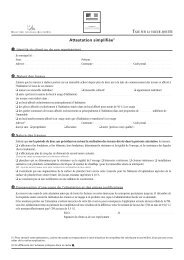
14 - SCHEMA ELECTRIQUESCHEMA DE CABLAGE GENERALTableau de bordInterrupteur marche / arrêtRécepteur HFElectrodesTerreCarteélectroniqueVersRIF 5000230VManostat d’airTerreMoteur dev<strong>en</strong>tilateurTransformateurd'allumageSondedépartSécurité de surchauffeBloc gazSonde corps de chauffeCirculateurMoteur de Vannede régulationSondesanitaireCapteur depression d’eauDispositif de contrôle del’évacuation des produitsde la combustion(seulem<strong>en</strong>t sur modeles“tirage naturel”)OU22
15 - ANOMALIE : Aide au diagnostic16 - CARACTERISTIQUES TECHNIQUESTypeUnitéHYDROMOTRIXEVOLUTIONHYDROCONFORTEVOLUTIONPRESTIGEEVOLUTIONPuissance Maxi kW 25 32 4580 / 1202525 32 45Catégorie II 2Esi 3P II 2Esi 3P II 2Esi 3P II 2Esi 3P II 2Esi 3P II 2Esi 3P II 2Esi 3PDébit calorifique Maxi kW 26,30 33,70 47,5 26,30 26,30 33,70 47,5Débit gaz Lacq G20 (20mbar) m3/h 2,780 3,563 5,022 2,780 2,780 3,563 5,022Débit gaz Groningue G25 (25mbar) m3/h 3,234 4,144 5,841 2,956 3,234 4,144 5,841Débit gaz Propane G31 (37mbar) kg/h 2,042 2,616 3,687 2,042 2,042 2,616 3,687Débit ECS D 30K l/mn 12,5 15,5 19 20 / 24 12,5 15,5Pression Maxi ECS bar 10 10 10 7 10 10Température Maxi chauffage °C 85 85 85 85 85 85 85Alim<strong>en</strong>tation électrique V 230 230 230 230 230 230 230CapacitéVase l*Installation l111351215018220111351822018220Pression Maxi chauffage bar 3 3 3 3 3 3 3* Ces chiffres ne sont pas théoriques mais correspond<strong>en</strong>t à la réalité constatée sur les installations.23