

H57752-v00 Manuale Istruzioni VTNC - Rhoss
H57752-v00 Manuale Istruzioni VTNC - Rhoss
H57752-v00 Manuale Istruzioni VTNC - Rhoss
- No tags were found...

Create successful ePaper yourself
Turn your PDF publications into a flip-book with our unique Google optimized e-Paper software.
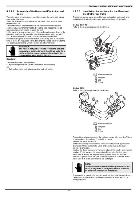
SECTION II: INST ALL ATION AND MAINTEN ANCEII.2.5.5 Assembly of the Motorised ElectrothermalValveThe unit c ontrol circuit makes it possi ble t o open t he motorised val ves(see wiring diagrams).When t he thermos tat c alls cold or hot, ter minal 1 and termi nal 2 arepowered at 230V.The control circuit undertakes t o run t he c ondens ation dr ain pumpcontinuously when the thermostat, by calling cold, keeps the chilledwater regulation valve open towards the coil.In the event of an anomalous rise in the condensation water level in thecollection tray (due, for example, t o a defecti ve drain, f ault y f an, etc .),this causes t he float K3 cont act t o open and the control circuitundertakes to operat e t he c ondensati on drain pump and, at t he s ametime, to cl ose the regulation valve, bloc king the c hilled wat er flow t o t hecoil and thus preventing further c ondens ation from f orming.II.2.5.6 Installation Instructions for the MotorisedElectrothermal ValveThe el ectrot hermal val ve ass embl y must be installed on t he unit af terinstallation, f ollowing the di agrams and on the basis of t he model.Models 26-36-46Refer to the di agram provided in the kit box.WA2A1ATTENTION !The valve is not j ust needed to control the ambienttemperature, but also to block the chil led water flo wto the coil in the case of an anomalous rise in thecondensation water level in the tray.RegulationThe wat er flow mus t be controlled:• by installing motorised valves supplied as an accessor yor:• by installed motorised valves supplied by the installerWA1A2A3Wat er connec tionRing nutSealFittingModels 60-85Refer to the di agram provided in the kit box.A2A1A3A2A1WWA1A2A3Wat er connec tionRing nutSealFittingConnect t he val ve assembl y t o t he coil and s ecure it by appl ying Teflonor, alter nati vel y, thread seal ( Loctit e®) or hemp.Insulate the val ve assembl y.Install the auxiliar y tray under the valve assembly, inserting the smalldrain pi pe i n the s pecific hole. Level and secur e it usi ng the threescrews (B) pr ovided.Insulate t he three screws and the lower edge of the tray by appl ying t heinsulant (F). As regards the connection of the s yst em's st eel pipes,make sure that t hey are aligned and supported so as not to placeanomal ous pressure on t he unit. When the s yst em is filled with wat er,make sure that all the connections are watertight.NOTE:The valve assembl y seal efficien cy is tested in thefactory. An y leaks in the system should thereforebe attributed to incorrect inst allation.To connec t the valve t o t he electric panel, run the cable through the unitcable gland and connect it t o t he termi nal boar d as illustr ated in thewiring diagrams.44


