

H57752-v00 Manuale Istruzioni VTNC - Rhoss
H57752-v00 Manuale Istruzioni VTNC - Rhoss
H57752-v00 Manuale Istruzioni VTNC - Rhoss
- No tags were found...

Create successful ePaper yourself
Turn your PDF publications into a flip-book with our unique Google optimized e-Paper software.
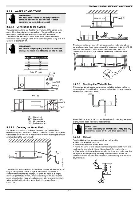
SECTION II: INST ALL ATION AND MAINTEN ANCEII.2.5WATER CONNECTIONSII.2.5.1IMPORTANT !The water connections are very important andparticular care should be dedicated to theseoperations b y specialist personnel.Connection to the SystemThe wat er connections are fixed to the struct ure of t he unit so as t oprevent breakage during t he c onnecti on of t he pipes. However, werecommend hol ding the connection in place wit h a spanner.The t op c oil connec tion has an air bl eed val ve, while t he bottomconnection has a drai nage valve which can be adjust ed using a 10 mmspanner or a screwdri ver.<strong>VTNC</strong>250<strong>VTNC</strong>IMPORTANT !The coil can only be partly drained. For completedrainage we recommend blowing air into the coil.The pi pes mus t be covered wit h anti-condensation material, s uch aspol yuret hane, propylene, neoprene or ot her expanded materials of 5- 10mm thic k. In the cas e of several units installed i n one r oom, thecondensation collection pipe must be installed as illustrated in thefigure.Model Ø connection s26 ¾”36 ¾”46 ¾”60 ¾”85 ¾”<strong>VTNC</strong><strong>VTNC</strong>26 - 36 - 46V1INOUTV2II.2.5.3 Creating the Water SiphonThe condens ation drai nage s yst em must i nclude a suitable si phon t oprevent odours from infiltrati ng the room. Instruc tions on how to createa wat er siphon are given bel ow.60 - 85V2INV1OUT50 mm100 mmINOUTV1V2Water inletWat er outletAir bleed val veDrainage val veII.2.5.2 Creating the Water DrainFor regular condensation drainage, the drain pipe must be tilt eddownwards by 2%, wit h no bottl enec ks . There shoul d also be a si phon,with access for ins pecti on, at l east 50 mm down in order t o prevent badsmells entering t he environment .<strong>VTNC</strong>2%Always include a cap at the bot tom of the siphon f or cleaning purposes ,or ens ure t hat it can be quic kl y disass embled.IMPORTANT !Position the drain pipe so that it does not place an ymechani cal stress on the unit drain connection.II.2.5.4 ChecksOnce installation has been completed, you will need to:• Bleed the air out of the circuit.• Make sure that t here are no water l eaks.• Cover the val ve (if pres ent) and connection pipes c arefull y with anticondensationmaterial of 10 mm thick or install the auxiliary trays.• Pour water int o t he c ondensati on c ollection trays and make sure thatthe liquid is drained properly, following its c ourse until it l eaves thecondens ation drai n. If this does not occur, c hec k the angle and look f orany bloc kages.50The wat er can be dr ained at a maximum of 250 mm above the unit, aslong as t he upwar ds stretc h of pi pe is vertical and positi oned incorrespondence to the drai n flange. To drain the wat er at a heightabove the per mitted 250 mm, install an auxiliary condensation drainpump with collecti on tr ay and l evel regulator. We rec ommend modelswith a s afety float to stop the water flow in the cause of pumpmalfunction.43


