

H57752-v00 Manuale Istruzioni VTNC - Rhoss
H57752-v00 Manuale Istruzioni VTNC - Rhoss
H57752-v00 Manuale Istruzioni VTNC - Rhoss
- No tags were found...

You also want an ePaper? Increase the reach of your titles
YUMPU automatically turns print PDFs into web optimized ePapers that Google loves.
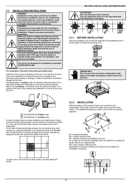
SECTION II: INST ALL ATION AND MAINTEN ANCEII.2INSTALLATION INSTRUCTIONSDANGER!Install ation must onl y b e carri ed out b y skil ledtechnicians, qualified to work on air conditioningand cooling syst ems. Incorr ect in stall ation couldcause the unit to run poorly, with a consequentnoticeabl e deter ioration in p erformance.DANGER!The personnel must install the unit according tonational or local regulations in force at the time ofinstall ation. Al ways u se p erson al protectiveequipment.Make sure that the voltage and frequ ency of theelectrical system meet requir ements and that theavailabl e in stall ed po wer is sufficient for theoperation of other domestic appliances connectedto the same po wer lines. Make sure that the po wersupply net work corresponds to current nation alsafet y standard s. Make sure that the unit iseffectivel y earthed.The unit's condensation drain pipe should only b eextended with a PVC pipe (not provided) of asuitable length and di ameter for instal lation, andshould be in sulated.The unit is not designed for installation in laundries(CEI EN 60335-2-40).II.2.1ATTENTION !Do not close mor e than 2 mouths.Do not restrict the air flo w in an y way other thanthat illustrated in the figure.BEFORE INSTALLATIONCarry the pac kaged unit as clos e as possi ble t o t he ins tallati on s pot . Itwill be easier to install the unit using a lift.<strong>VTNC</strong><strong>VTNC</strong>For installation, follo w the instructions provided b elo w:Install t he unit as clos e as possible to the room. T he direction of the airflow c an be adjusted by moving t he louver fi ns acc ording to theoperating mode (cooling or heating), in order t o opti mise air distributionthroughout the room.During operati on i n cooling mode, t he opti mal l ouver fin position (2) isthat which enables the outcoming air to br ush the ceiling (Coandaeffec t). During heating, on the ot her hand, the optimum position (1) ispoint ed at the floor, thus avoiding t he s tratificati on of hot air at the t op ofthe room.IMPORTANT !Do not move the unit by the condensation drainpipe or the water connections. Hold it b y the fourcorners.21 fin positioned for heating mode2 fin positioned for cooling modeIn order to enabl e quic k and eas y installation and maintenanc e, makesure that the false ceiling panels can be removed in the chosen positionor, in the case of brickwor k false ceilings, that access to the unit isguarant eed.In the case of plasterboard false ceilings, the unit housing area mustmeasure no more t han 660x660 mm ( models 26-36-46) and 900x900mm (models 60-85). In the cas e of damp environments , insul ate thehanging brac kets with specific self-adhesi ve ins ulants .1II.2.2INSTALLATIONMark t he position of t he s upport braces , the c onnection andcondens ation drai n pi pes, the power cables and any wired c ontrolcables. The cardboar d templat e, pr ovided, c an be usef ul during thisoperation.FCVF1F2D = cardboard t emplat eFC = central ref erenc e holeF1 = hol e for s ecuring the t emplat e t o t he unitV = screws for s ecuring the t emplat e t o the unit (M5X16 for models 26-36-46 / M6x16 for models 60-85)F2 = brace position r eference hol eDepending on the type of ceiling, the braces can be installed asillustrated in the figure.DTo close one or mor e of the air outl et mouths, us e the s pecific KIT(KCB).38


