

H57752-v00 Manuale Istruzioni VTNC - Rhoss
H57752-v00 Manuale Istruzioni VTNC - Rhoss
H57752-v00 Manuale Istruzioni VTNC - Rhoss
- No tags were found...

Create successful ePaper yourself
Turn your PDF publications into a flip-book with our unique Google optimized e-Paper software.
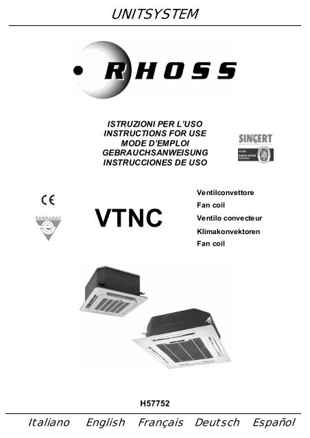
UNITSYSTEMISTRUZIONI PER L’USOINSTRUCTIONS FOR USEMODE D’EMPLOIGEBRAUCHSANWEISUNGINSTRUCCIONES DE USO<strong>VTNC</strong>VentilconvettoreFan coilVentilo convecteurKlimakonvektorenFan coil<strong>H57752</strong>Italiano English Français Deutsch Español
Dichiarazione di conformitàLa s ocietà RHOSS S.p.A.con s ede a Arquà Polesine (RO), via delle I ndustrie 211, dic hiara, s ott o lapropria esclusiva responsabilità, che i prodotti della serie<strong>VTNC</strong> 26-36-46-60-85sono conformi ai requisiti essenziali di sicurezza di cui alla DirettivaMacchine 2006/ 42/CE.------------La macc hina è inoltre c onf orme alle seguenti diretti ve:- 2006/95/CE (Bassa T ensione).- 2004/108/CE (Compatibilità Elettromagnetica).Statement of conformityRH OSS S.p.A.located in Arquà Polesine (RO), via delle Industrie 211, hereby states onits own exclusive responsibility that the products in the<strong>VTNC</strong> 26-36-46-60-85are compliant with the ess ential safet y r equirements as set f orth inMachine Directi ve 2006/42/CE.------------The mac hine is also c ompliant with the following direc tives:- 2006/95/CE (Low Voltage).- 2004/108/CE (Electromagnetic Compatibility).Déclaration de conformitéLa s ociété RHOSS S.p.A.dont le siège se tr ouve à Arquà Polesine (RO), via delle I ndustrie 211,déclare, sous sa r esponsabilité exclusive, que les produits de la série<strong>VTNC</strong> 26-36-46-60-85sont c onf ormes aux car actéristiques de s écurité requises par la Directi veMachines 2006/ 42/CE.------------L’appareil es t par ailleurs c onf orme aux directi ves sui vant es :- 2006/95/CE (Basse T ension).- 2004/108/CE (Compatibilité Electromagnétique).KonformitätserklärungDer Hersteller RHOSS S.p.A.mit Geschäftssitz in Arquà Polesine (RO), via delle I ndustrie 211, erklärteigenverantwortlich, dass die Geräte der Baureihe<strong>VTNC</strong> 26-36-46-60-85den grundsätzlichen Anforderungen an die Sic herheit in Übereinsti mmungmit der Maschinenrichtlini e 2006/42/EG entspr echen.------------Darüber hinaus entspricht di e Maschi ne f olgenden Richtlinien:- 2006/95/EG, (Nieder Spannung).- 2004/108/ EG (Elektromagnetische Verträglichkeit).Declaración de conformidadLa empresa RHOSS S.p.Acon s ede en Arquà Polesi ne (RO), via delle Industrie 211, declar a bajo s uúnica res ponsabilidad que los product os de la serie<strong>VTNC</strong> 26-36-46-60-85Se encuentr an en c onformi dad con los principales requisitos deseguridad i ndicados en la Directi va de máquinas 2006/ 42/C E.------------La máquina, además, s e encuentra en confor midad con las siguient esdirectivas:- 2006/95/CE, (Baja T ens òn).- 2004/108/C E (Compati bilidad elec tromagnétic a).Codroipo, lì 16 dicembre 2010Il direttor e generale / General manager / Directeur général / Generaldirektor / Direct or generalPierluigi Ceccolin
SEZIONE I: UTENTEINDICESIMBOLOGIA UTILIZZATAItaliano pagina 4English page 27Français page 50Deutsch Seite 73Español página 96I SEZIONE I: UTENTE ............................................................................... 5I.1 Descrizione................................................................................................5I.1.1 Condizioni di utilizzo previste...........................................................................5I.1.2 Identificazi one ..............................................................................................5I.1.3 Caratteristiche costruttive ...............................................................................5I.1.4 Limiti di funzionamento...................................................................................5I.1.5 Informazioni sugli usi non consentiti..................................................................5I.1.6 Informazioni sui rischi residui e pericoli che non possono essere eliminati.................5I.2 Accessori e ricambi .....................................................................................6I.2.1 Accessori e ricambi forniti di serie.....................................................................6I.2.2 Accessori e ricambi forniti separatamente ..........................................................6I.2.3 Coman di e contro lli forn iti di seri e .....................................................................6I.2.4 Coman di e contro lli forn iti separ atamente...........................................................6I.3 <strong>Istruzioni</strong> di utilizzazione..............................................................................6I.3.1 Telecomando ...............................................................................................7I.3.2 Impostazione dell’orologio...............................................................................8I.3.3 Accensione spegnimento dell’unità ...................................................................8I.3.4 Impostazione del modo di funzionamento...........................................................9I.3.5 Funzione economic running ............................................................................9I.3.6 Impostazione della temperatura desiderata ........................................................9I.3.7 Impostazione del deflettore .............................................................................9I.3.8 Impostazione della ventilazione........................................................................9I.3.9 Impostazione deI Timer..................................................................................9I.3.10 Blocco della tastiera ......................................................................................9I.3.11 Reset del telecomando...................................................................................9I.4 GUIDA RAPIDA AL FUNZIONAMENTO ......................................................... 10I.4.1 Funzionamento automatico ........................................................................... 10I.4.2 Funzione raffrescamento .............................................................................. 10I.4.3 Funzion e deum idific azio ne ............................................................................ 10I.4.4 Funzione riscaldamento ............................................................................... 10I.4.5 Funzione ventilazione .................................................................................. 10I.4.6 Funzioni di comfort ...................................................................................... 10I.4.7 Descrizi one d egl i ind icatori d ell ’un ita’ .............................................................. 11I.4.8 Unità in allarme .......................................................................................... 11I.5 Pulizia dell’unità........................................................................................ 11I.5.1 Pulizia del filtro aria ..................................................................................... 11I.6 Avvertenze e suggerimenti ......................................................................... 11I.6.1 Messa fuori servizio..................................................................................... 12I.6.2 Riavvio dopo lunga inattività.......................................................................... 12II SEZIONE II: INSTALLAZIONE E MANU TEN ZIONE ............................. 13II.1 <strong>Istruzioni</strong> di trasporto ................................................................................ 13II.1.1 Imballo, componenti .................................................................................... 13II.1.2 Indicazioni per la movimentazione .................................................................. 13II.1.3 Cond izio ni di imm agazz inam ento ................................................................... 13II.1.4 Spazi di ris petto, posizi onam ento ................................................................... 13II.2 <strong>Istruzioni</strong> di installazione............................................................................ 15II.2.1 Prima dell’installazione................................................................................. 15II.2.2 installazione............................................................................................... 15II.2.3 Montaggio dell’assieme cornice/griglia............................................................. 17II.2.4 Aria esterna d i rinn ovo e man data ari a trattata in local e attiguo (so lo per i mo del li 60- 85)............................................................................................................... 18II.2.5 Coll egam enti idr aul ici ................................................................................... 20II.2.6 Coll egam enti el ettrici ................................................................................... 22II.3 <strong>Istruzioni</strong> per l’avviamento ......................................................................... 25II.3.1 Controlli preliminari all’avviamento.................................................................. 25II.4 <strong>Istruzioni</strong> di manutenzione......................................................................... 25II.4.1 Manutenz ion e ordi nari a ................................................................................ 25II.4.2 Manutenz ion e straordi nari a ........................................................................... 26II.5 Indicazioni per lo smantellamento dell’unità e smaltimento sostanze dannose. 26ALLEGA TIA1A2A3Dati tecnici……………………………………………………………………...….…...119Dimens ioni…………………………………………………………………..….………124Schemi elettrici……………………………………………………………..……..……127SIMBOLOUNI EN 292UNI EN 294UNI EN 563UNI EN 1050UNI 10893EN 13133EN 12797EN 378-1PrEN 378-2CEI EN 60335-2-40UNI EN ISO 3744EN 50081-1:1992SIGNIFICAT OPERICOLO GENERICO!L’indicazion e PERICOLO GEN ERICO è u sata perinformare l’operatore ed il personale add etto allamanutenzione di rischi ch e possono comportare lamorte, danni fisici, malattie in qualsivoglia formaimmediat a o latente.PERICOLO COMPONENTI IN TENSION E!L’indicazion e PERICOLO COMPONENTI INTENSIONE è usata per informare l’operatore ed ilpersonale add etto alla manutenzione circa i rischidovuti alla presenza di tensione.PERICOLO SUPERFICI T AGLIENTI!L’indicazion e PERICOLO SUPERFICI TAGLIENTI èusata per informare l’op eratore ed il personaleaddetto alla manutenzione dell a pr esenz a disuperfici potenzialm ente per icolo se.PERICOLO SUPERFICI CALDE!L’indicazion e PERICOLO SUPERFICI CALDE èusata per informare l’op eratore ed il personaleaddetto alla manutenzione dell a pr esenz a disuperfici calde potenzi almente peri colose.PERICOLO ORGANI IN MOVIMENTO!L’indicazion e PERICOLO ORGANI IN MOVIMENTO èusata per informare l’op eratore ed il personaleaddetto alla manutenzione circa i rischi dovuti allapresenz a di org ani in movimento.AVVERTENZE IMPORT ANTI!L’indicazion e AVVERTENZE IMPORT ANTI è usataper rich iamare l’attenzione su azioni o pericoli ch epotrebbero creare danni all’unità o ai suoiequipaggiamenti.SALVAGUARDIA AMBIENTALE!L’indicazion e salvaguardia ambientale fornisceistruzioni per l’utilizzo d ella macchin a nel risp ettodell’ambiente.Riferimenti normativiSicurezza del macchinario. Concetti fondamentali,principi generali di progettazioneSicurezza del macchinario. Distanze di sicurezza perimpedire il raggiungimento di zone pericolose con gli artisuperiori.Sicurezza del macchinario. Temperature delle superficidi contatto. Dati ergonomici per stabilire i valori limiti ditemperatura per superfici calde.Sicurezza del macchinario. Principi per la valutazione delrischio.Documentazione tecnica di prodotto. <strong>Istruzioni</strong> per l’usoBrazing. Brazer approvalBrazing. Destructive tests of brazed jointsRefrigeration systems and heat pumps – safety andenvironmental requirements. Basic requirements,definitions, classification and selection criteriaRefrigeration systems and heat pumps – safety andenvironmental requirements. Design, construction,testing, installing, marking and documentationSicurezza degli apparecchi elettrici d’uso domestico esimilare. Parte 2: Norme particolari per le pompe dicalore elettriche, per i condizionatori d’aria e per ideumidificatori.Determinazione dei livelli di potenza sonora dellesorgenti di rumore mediante pressione sonora. Metodotecnico progettuale in un campo essenzialmente liberosu un piano riflettente.Electromagnetic compatibility - Generic emissionstandard Part 1: Residential, commercial and lightindustry4
SEZIONE I: UTENTEISEZIONE I: UTENTEI.1 DESCRIZIONE<strong>VTNC</strong> è una unit à ter minal e di tratt ament o aria (ventilconvettore), tipo“cassette”, per i nstallazione in c ontros offitt o, c on ripres a e mandat a ariadirettamente in ambiente.I.1.1 CONDIZIONI DI UTILIZZO PREVISTE<strong>VTNC</strong> è un ventilconvettore per il trattamento dell’aria (climatizzazioneestiva e inver nale) all’interno di ambienti ad uso domestico o similare.L’unità non é destinata all’installazione in locali ad uso lavanderia(norma CEI EN 60335-2-40).Le unità sono c onf ormi alle seguenti Diretti ve:- Direttiva macchine 2006/42/CE (MD);- Direttiva bass a t ensione 2006/95/CE (LVD);- Direttiva compatibilità elettromagnetica 2004/108/CE (EMC).PERICOLO!L’installazione d ell’unità è prevista solo all’interno,in ambienti ad uso dom estico e simi lari .PERICOLO!E’ vietato introdurre oggetti attraverso le bocche diaspir azione e mand ata aria.IMPORTANTE!Il corretto funzionamento dell’unità è subordinatoalla scrupolosa osservanza delle istruzioni d’uso, alrispetto degli spazi tecnici n ell’in stallazione e deilimiti di impiego riportati nel presente manuale.IMPORTANTEUn’installazione che non soddisfi gli spazi tecniciconsigliati causerà difficolt à di manutenzione e unariduzione delle prestazioni.I.1.2 IDENTIFICAZIONELe unità sono provviste di una targa matricola posta all’interno e visibileaprendo la griglia.I.1.4LIMITI DI FUNZIONAMENTOIMPORTANTE!Una installazione che non soddisfa i limiti difunzionamento indicati solleva RHOSS S.p.A. daogni responsabilità in caso di danni a co se o apersone.Circuito acqu a• Pressione massima lat o acqua: 1600 kPa ( 163 m c.a.)• Temperat ura minima acqua entrante: + 4°C• Temperat ura massi ma acqua entr ant e: + 75°CAri a ambi ente• Temperat ura minima: 5°C (1)• Temperat ura massi ma: 32°CNota: (1) Se si prevede che la temper atura amb ientepossa scendere sotto 0°C, si r accomanda disvuotare l'impianto acqua onde evitare possibilirotture da gelo (vedere paragrafo "Colleg amentiIdraulici").Alim entazione el ettrica unità• Tensione nominal e monof ase 230V ~ 50HzI.1.5I.1.6INFORMAZIONI SUGLI USI NON CONSENTITIIMPORTANTE!La macchina è stata progettata e costruita solo edesclusivamente per funzionare come unitàterminale per il trattamento dell’aria; ogni altro usodiverso da questo è espr essam ente vietato. E’vietata l’in stallazione d ella macchin a in ambienteesplosivo.INFORMAZIONI SUI RISCHI RESIDUI EPERICOLI CHE NON POSSONO ESSEREELIMINATIIMPORTANTE!Prestare l a m assima attenzione ai simboli e all eindicazioni posti sulla macchina.UNIT - <strong>VTNC</strong>COOLING CAPACITYHEATING CAPACITY 50°HEATING CAPACITY 70°V - PH - HZRATED INPUTCLASS: T1IPX0XX0,000,000,00230-1-50XXNel caso i n cui permangano dei rischi malgrado tutte le dis posizioniadottate, ovvero si tratti di rischi potenziali e non evi denti, sono stateapplicate s ulla macchi na delle targhet te adesive s econdo quantoindicato dalla norma ISO 3864.NNNNNNNNNNNNeI.1.3 CARATTERIS TICHE COSTRUTTIVE• Strutt ura autoportant e in lami era zinc ata completa di dispositi vo peril sollevamento della condensa dalla vaschetta al livello di scarico,plafonat ura di tamponamento c on alet te di mandat a mot orizzateorientabili (deflettori), griglia di ripresa e filtro rigenerabile.• Scambiat ore di calore a bat teria alett ata.• Ventilatore a tre velocità.• Vaschetta ausiliaria raccogli condensa.I.1.3.1 Versioni• <strong>VTNC</strong> Ventilconvettore a 2 t ubi5
SEZIONE I: UTENTEI.2 ACCESSORI E RICAMBIIMPORTANTE!Utilizzare solo ed esclusivamente r icambi eaccessori origin ali.RH OSS S.p.A. declina ogni responsabilità perdanni cau sati da manomissioni o interventi eseguitida person ale non autorizzato o per disfunzionidovute all’uso di ricambi o accessori non origin ali.IMPORTANTE!Qualora ci si trovi in pr esenz a di acqueparticolar mente r icch e di cal care è con sigli abilel’utilizzo di un decalcificatore.I.2.3 COMANDI E CONTROLLI FORNITI DI SERIE• TelecomandoTelecomando completo di pile di alimentazione. Per l’utilizzo fareriferiment o al paragraf o I. 3.1I.2.1ACCESSORI E RICAMBI FORNITI DI SERIEVA - Vaschetta ausiliaria raccoglicondensa.Per i modelli 26-36-46Per i modelli 60-85(Dimensioni 60 x 165 x 18 mm)I.2.4 COMANDI E CONTROLLI FORNITISEPARATAMENTE• KPFPannello comando a filo con display a cristalli liquidi, a 10 tasti, per laregolazione manuale di tutt e le funzioni dell’apparecchio in base allatemperatura ambiente prescelta. Il pannello è predisposto per il fissaggioa paret e.Per le istruzioni di montaggio e di utilizzo del pannello di comando fareriferimento alle istruzioni per l’uso f ornite con lo stesso.I.2.2ACCESSORI E RICAMBI FORNITISEPARATAMENTEKV3 - Elettrovalvola a 3 vie per impianti a 2 tubi (vaschetta ausiliariaraccoglicondensa present e di s erie su ogni unità).Modelli 26-36-46 (¾” – 30 Nm)WA2A1(Dimensioni 120 x 120 x 18 mm)Modelli 60-85 (¾” – 30 Nm)I.3 ISTRUZIONI DI UTILIZZAZIONETramite il tel ecom ando e/ o il pannello comando a filo (KPF) (vediistruzioni per l’uso f ornite con lo s tesso) è possibile eseguire le seguentioperazi oni:• Accensione/spegni mento dell’unità.• Scelta delle tre velocità del ventilatore.• Regolazione del ter most ato e mant enimento in ambient e dellatemperatura desiderat a.• Commut azione del ciclo di funzionamento:raffrescamento/riscaldamento.Sulla pl afonat ura dell’unit à s ono pres enti degli indicatori cheforniscono informazioni s ullo st at o dell’unità o eventuali segnalazi oni diallarme e, qualora non f osse t empor aneamente disponibile iltelecomando e/o il pannello comando (KPF) consentono, utilizzando iltasto MANUAL, di gestire l’unit à in modalità manuale.KCB – Chiusura bocchette di mandata (solo modelli 60-85).6
SEZIONE I: UTENTEI.3.1 TELECOMANDOIl telec omando permett e di i mpost are e visualizzare tut ti i parametri difunzionamento dell’unità, facilitando così tutte le oper azioni diprogrammazione.Il telec omando é ali mentat o c on 2 batt erie R03 size AAA da 1, 5 V.IMPORTANTE!E’ consigliab ile t estare il funzionamento deltelecomando per determinare la sua zona diricezion e.I.3.1.1Descrizione telecomando e relative funzioniN° TASTO FUNZIONE DESCRIZIONE1 /2 /34567891011Emettitore disegnaliDisplay acristalli liquidiAccensione/Spegni mentoSelezione delprogramma difunzionamentoImpostazionedellatemperaturaImpostazionevel ocità delventilatoreImpostazioneposizionedeflettoreSelezionedeflettoremotorizzatoFunzionamentoeconomicImpostazioneaccensi one/spegniment ocon ti merImpostazioneorari12 Confer ma13141516RegolazioneorologioBloccotelecomandoResettelecomandoCancellazionetimerTrasmet te i s egnali infrarossi alricevitore dell’unitàIndica gli stati e i modi difunzionamento dell’unitàPermette di accendere espegnere l’unità. Premer e iltasto per accendere, premerenuovamente per spegnerePermette di s elezionare il tipo difunzionamento desiderato(AUTO, COOL, DRY, HEAT,FAN)Questi tasti permett ono diimpos tare l a temperat uraambient e desiderata.la temperat ura richiest a vieneincrement ata fino a 30 °Cla temperat ura richiest a vienedecrementat a fi no a 17 °COgni pressione corrisponde unavariazi one di 1°CPremere quest o t asto perselezionare la velocità delventilatore. Quando si sel ezionaAUTO la vel ocità del ventilat oreviene regol ata automatic ament ea sec onda della t emperaturadell’ambiente. È possibileselezionare anche manualment ela velocità del ventilator escegliendo tra 3 regolazioni:LOW = MINIMA; MED = MEDIA;HIGH = MASSIMAPermette di s elezionare l’angolodi inclinazione del defl ett oreQuest o t asto per met te aldeflettore di oscillare in manieracostanteQuest a f unzione non èdisponibile nelle unità <strong>VTNC</strong>.Premere questi tasti perpredisporre lospegniment o/acc ensi onedell’unit à con ti merPermette di i mpos tare l’or ariodell’orologio e dei timerPremere quest o t asto perconf ermare gli orari sceltiPremere quest o t asto per piùsecondi per la regolazionedell’orologioPermette di bloccare ognifunzionalità del telec omandoPremere quest o pulsante perresettar e le i mpostazioni deltelecomandoPremere quest o t asto perannullare il f unzionamento contimer7
SEZIONE I: UTENTEI.3.1.2Descrizione del display1) Indicator e di trasmi ssioneAppare ogni volta c he si tras met te un s egnale all’unit à int erna.2) Visualizzazione d el programma di funzionamento (MODE)Indica il tipo di f unzionamento presc elto.3) Visu alizz azione ON/OFFIndica che l’unit à è i n f unzione.4) Visu alizz azione d ella temper atura (TEMP)Indica la t emperatura i mpostata (da 17 °C a 30 °C). Q uando si sceglie ilprogramma di funzionamento F AN non viene vis ualizzat a nessunatemperatura.5) Visu alizz azione d ell’orologioÈ sempre atti va, indica l’ora att ual e.6) Visu alizz azione d el timer (TIMER ON)Se si pr eme il tas to TIMER ON viene visualizzato l’orario di accensionecon ti mer.7) Visu alizz azione d el timer (TIMER OFF)Se si pr eme il tas to TIMER OFF viene visualizzato l’orario dispegniment o con ti mer.8) Visualizzazione di bloccoIndica che il telec omando è bloccato.9) Visu alizz azione ECONOMICIndica che la funzione ECONOMIC RUNNING è attiva (Questa funzionenon è gestit a nelle unit à <strong>VTNC</strong>).10) Visualizzazione della velo cità del ventilatore (FAN)Indica la vel ocità del ventilatore s elezionat a. Può ess ere visualizzatoAUTO o uno dei tre livelli di velocità: MINIMA (LOW), MEDIA (MED),MASSIMA (HIGH).I.3.1.3 Uso del telecomandoIl telec omando utilizza due batterie alcaline da 1,5 V del tipo R03 sizeAAA (fornite i n dotazi one).Per inserire le batterie, sfilare completamente il coperchio deltelecomando f acendolo slittar e verso la parte i nferiore. Ins erire lebatt erie nell’apposito alloggiamento rispett ando l e polarità i ndicat e.Riposizionare il coperchio e s elezionare le funzioni desi derat e. Stess aoperazi one deve essere fatta per la sostit uzione delle bat terie sc arichecon altre batt erie nuove. La durat a media delle bat terie é di circa unanno.Il telec omando é in grado di tras mett ere fi no ad una dist anz a di circa 8metri dal ricevitore.Evitare l’esposizione del telecomando all’umidità eccessiva, alla lucesolare diretta o ad altre f onti di cal ore ed evit are gli urti. Proteggere iltelecomando dall’acqua o altri liquidi.Se il ricevitore a raggi infrarossi dell’unità è esposto a luc e s olare direttao a l uce intensa di una l ampada oppure nelle vicinanz e è pres ent e unalampada fluorescente con acc ensione elet tronica, l’unit à potrebbepresentare anomalie di funzionamento o non funzionare.L’utilizzo di altri telec omandi nelle vicinanze o nello s tesso ambient e incui é ins tallat a l’unit à potrebbe infl uenz arne il regolare f unzionamento;evit are di rivolgere il trasmettit ore di altri tel ecomandi vers o il ricevit oredell’unit à.I.3.2 IMPOSTAZIONE DELL’OROLOGIOQuando si inseriscono l e batt erie nel tel ecomando, l’indicatore orariovisualizza 0:00 lampeggiant e.Nota: durante l’impostazione dell’orologio non rivolgere il telecomandovers o l’unit à.Si consiglia di regolare l’orologio sul telecomando prima di avviarel’unità; per la regolazione operare nel seguent e modo:premere il tas to TIME AD JUSTfinchè non viene vis ualizzat a l’oradesideratapremere OK per conf ermare l’oraimpostata (non dirigere iltelecomando vers o l’unit à)Per regolare nuovamente l’orario o eff ett uare una nuovaprogrammazione nel s eguente modo:I.3.3premere il tas to CLOCK per più ditre secondipremere il tas to TIME AD JUSTfinchè non viene vis ualizzat a l’oradesideratapremere OK per conf ermare l’oraimpostata (non dirigere iltelecomando vers o l’unit à)ACCENSIONE SPEGNIMENTO DELL’UNITÀPremere il tas to ON/OFF per accendere o spegnerel’unitàNel pass aggio da ON a OFF viene interrotto qualsiasi modo difunzionamento, cancellate le temporizzazioni i n corso, memorizzati ilmodo di funzionamento dell’appar ecchio e del ventilat ore ed il val ore ditemperatura i mpostato.Nel pass aggio da OFF a ON l’unità ripristina automaticamente tutte lemodalità di f unzionamento memorizzate prima dello spegniment o.Ad unità acces a s ul displ ay compare l’indic azione diunità acces a.La presenza di quest o simbol o sul display i ndica c he iltelecomando sta trasmettendo le impostazioni all’unità.Il telec omando rimane sempr e con il displ ay acc eso.Rimuovere le bat terie dal t elec omando s e si prevede di non utilizzarloper lunghi periodi.Il display del t elec omando vis ualizza s empre l’orario i ndipendentementedal f atto che l’unit à sia acces a o spent a.Rivolgere il telecomando verso il ricevitore dell’unità mentre sieffettuano le impostazioni (eccetto durante l’impostazione dell’orologio).Se i segnali vengono ricevuti correttamente, l’unità emetterà un segnaleacustico “beep”.8
SEZIONE I: UTENTEI.3.4IMPOSTAZIONE DEL MODO DIFUNZIONAMENTOPremendo più volt e il t asto Mode è possibile cambiar e ilmodo di funzionamento dell’unità. Sul display comparel’indicazione del modo di funzionament o s elezionat o:I.3.8IMPOSTAZIONE DELLA VENTILAZIONEPremendo più volt e il t asto FAN SPEED è possibileimpos tare l a velocit à del ventilat ore tr a le tr edisponibili, oppure attivare la funzione AUTO.Sul displ ay compare il modo di funzionamento:AUTO: funzionamento c omplet amente aut omaticoCOOL: funzione r affresc ament oDRY: funzione deumidific azioneHEAT: funzione riscaldament oFAN: funzi onament o sol o ventilazioneCon la sc elta del programma automatic o AUTO, l’unità può operare inRAFFRESCAMENTO ed in RISCALDAMENTO in base alla differenzadi temperatur a esist ent e tra la t emperatura ambiente e la temperat uraselezionata sul telecomando.Quando viene scelt o il pr ogramma di raffresc ament o COO L, l’unitàfunziona c on set di t emperatura libero, abbass ando la temperat ura inambient e.Quando viene scelt o il pr ogramma di deumidificazione DRY, l’unit àfunziona, con set di t emper atura libero, abbass ando c osìprogressivament e la t emper atura e l’umidit à in ambiente. Nelprogramma di deumidificazione DRY il tasto FAN SPEED non èutilizzabile.Quando viene scelt o il pr ogramma di riscaldamento HEAT, l’unitàfunziona, con set di t emper atura libero, alzando la t emper atura inambient e. Quando viene sc elto il programma di ventilazione F AN,l’unità f unziona senz a s et di temperat ura, ventilando l’ariadell’ambiente.I.3.9AUTO: funzionamento c omplet amente aut omaticoLOW: funzionamento velocità mini maMED: funzionamento velocità medi aHIGH: funzionamento velocit à massimaIMPOSTAZIONE DEI TIMERIMPORTANTE!Affinchè le impo stazioni d el timer abbiano effetto, iltelecomando deve essere SEMPRE posizion ato neipressi del l’unità (ad un a distanz a m assima d i 8metri) e rivolto verso la stessa.La f unzione TIMER non è ripetitiva e deve essere i mpostata ogniqualvolta si desidera utilizzarla.Quando viene sel ezionat a la f unzi one Timer ON-OFF, l'accensionedell'unità potrà avvenire c on un leggero ritardo rispett o all'orario ti merprogrammat o, ciò è da ritenersi del t utto normal e e rientra nel c orrettofunzionamento dell'unità.Premendo ques ti tas ti è possibile programmarel’orario di acc ensione e/o l’orario di s pegni mentodell’unit à.Il display vis ualizza le indic azioni TIMER ON e/ oTIMER OFF con parte dell’orario lampeggiante.IMPORTANTE!Il ventilatore dell’unità si ferma al raggiungimentodel valore di temperatura impostato per poiriattivarsi automaticamente alla velocità minima perevitare fenomenti d i stratificazion e del l’ar ia inprossimità dell’apparecchio.IMPORTANTE!Selezionando la funzione COOL DRY, il ventilatorepotrebbe non avviarsi subito perché presente lafunzione ANTI-HEATING (vedi paragrafo I.4.6.1).Selezionando la funzione HEAT, il ventilatorepotrebbe non avviarsi subito perché presente lafunzione ANTI-COOLING (vedi paragrafo I.4.6.2).TIME ADJUSTOrario di acc ensioneOrario di spegniment oPremendo ques to tast o è possibile modificarel’orario di acc ensione o di s pegni mento. Ad ognipressione del tas to l’orario viene increment ato odecrementat o di dieci minuti.L’orario di accensione o spegniment o impost ato,deve esser e confer mat o pr emendo il t asto OK.Il tasto CANCEL per mett e di disat tivare le funzioniTIMER ON e/o TIMER OFFI.3.5I.3.6FUNZIONE ECONOMIC RUNNINGQuest a f unzione non è disponi bile nelle unità <strong>VTNC</strong>.IMPOSTAZIONE DELLA TEMPERATURADESIDERATAPremendo ques ti tas ti nell e modalità AUTO, COOL,DRY, HEAT è possibile aumentar e o dimi nuire ilval ore della t emperatura desi derat a tra 17°C e 30°C. Ildisplay visualizza il valor e della temperaturaselezionato.I.3.7 IMPOSTAZIONE DEL DEFLETTOREPer ottenere una distribuzione ottimale dell’aria, regolar e la posizionedel deflet tore motorizzat o avendo cura c he il fl usso d’aria non inves tadirettamente le persone.Per il deflett ore mot orizzato agire nel modo seguent e:premendo più volte il t asto AIR DIRECTION èpossibile modificare l a posizione del deflet tore.Premendo il t asto SW ING è possi bile atti varel’oscillazione c ontinua del deflett ore.Una volt a impos tati gli orari di accensione espegniment o, il dis play visualizza l’oracorrente e le scritte TIMER ON e/ o TIMEROFF con i rel ati vi orari.I.3.10I.3.11BLOCCO DELLA TASTIERAPremendo c on un oggetto appuntito il t ast oBLOCCO/LOCK è possibile inibirecompletament e la tastier a del tel ecomandoevit ando usi indesiderati dello st esso(bambini, ecc.). Il display visualizzerà ilsimbol o riportato a fianco. Per rimuovere ilblocco della tasti era, premere nuovamentecon un oggetto appuntito il t astoBLOCCO/LOCK.RESET DEL TELECOMANDOPremendo c on un oggetto appuntito il t ast oRESET è possi bile riportare il tel ecomando alleimpos tazioni di f abbrica.PERICOLO!Muovere manualmente il deflettore motorizzatoquando l’unità è accesa potrebbe causare deiproblemi di funzionamento o danneggiare il sistemadi regolazione.9
SEZIONE I: UTENTEI.4 GUIDA RAPIDA AL FUNZIONAMENTOI.4.1 FUNZIONAMENTO AUTOMATICOCon la sc elta del programma automatic o AUTO l’unit à può operare inRAFFRESCAMENTO o in RISCALDAMENTO in bas e alla diff erenz a ditemperatura esistente tra la temperat ura ambient e e la t emper aturaselezionata sul telecomando.L’unità funzionerà in modo: Se:raffrescamento TA-TS > 1 °Cventilazione -1 °C ≤ TA-TS ≤ 1 °Criscaldament o TA-TS < -1 °CTA = temperatura ambient e TS = temperat ura sel ezionataI.4.2FUNZIONE RAFFRESCAMENTOPer impost are il funzionamento raffresc ament o COOL procedere comesegue:• selezionare il programma raf frescamento, agendo sul t ast o MODE(1), finché non appare s ul dis play la scritta COO L;• regolare la t emperatura desi derat a pr emendo i t asti TEMP (2) ildisplay indica valori da 17 °C a 30 °C;• regolare la vel ocità di ventilazione agendo s ul tas to FAN SPEED (3),scegliendo tra AUTO e le altre velocit à HIGH-MED-LOW;• rivolgere il tel ecomando verso il ricevit ore dell’unit à, e premere iltasto di acc ensi one ON/OFF (4);• regolare il flusso dell’aria secondo le esigenze utilizzando il tastoSWING (5) o AIR DIRECTION (6).Fatte l e regolazioni, ques te verranno ripropost e quando si riaccender àl’unità.Ogni segn ale trasmesso dal t elecomando, se ricevuto dall’unità,viene confermato da un doppio “beep”.I.4.3FUNZIONE DEUMIDIFICAZIONEPer impostare il funzionamento deumidificazione DRY procedere comesegue:• selezionare il programma deumidific azione, agendo sul tast o MODE(1), finché non appare s ul dis play la scritta DRY;• regolare la t emperatura desi derat a pr emendo i t asti TEMP (2) ildisplay indica valori da 17 °C a 30 °C;• rivolgere il tel ecomando verso il ricevit ore dell’unit à, e premere iltasto di acc ensi one ON/OFF (4);• regolare il flusso dell’aria secondo le esigenze utilizzando il tastoSWING (5) o AIR DIRECTION (6);Fatte l e regolazioni, ques te verranno ripropost e quando si riaccender àl’unità.Ogni segn ale trasmesso dal t elecomando, se ricevuto dall’unità,viene confermato da un doppio “beep”.Quando viene scelt o il pr ogramma di deumidificazione DRY, l’unit àfunziona c on set di t emperatura libero, abbass ando c osìprogressivament e la t emper atura e l’umidit à in ambiente.Nel programma di deumidificazione DRY, il tasto FAN SPEED non èutilizzabile.I.4.4 FUNZIONE RISCALDAMENTOPer impost are il funzionamento in riscaldament o HEAT pr ocedere c omesegue:• selezionare il programma riscaldament o, agendo s ul tas to MODE(1), finché non appare s ul dis play la scritta HEAT;• regolare la t emperatura desi derat a pr emendo i t asti TEMP (2): ildisplay indica valori da 17°C a 30°C;• regolare la vel ocità di ventilazione agendo s ul tas to FAN SPEED (3),scegliendo tra AUTO e le altre velocit à HIGH-MED-LOW;• rivolgere il tel ecomando verso il ricevit ore dell’unit à, e premere iltasto di acc ensi one ON/OFF (4);• regolare il flusso dell’aria secondo le esigenze utilizzando il tastoSWING (5) o AIR DIRECTION (6).Fatte l e regolazioni, ques te verranno ripropost e quando si riaccender àl’unità.Ogni segn ale trasmesso dal t elecomando, se ricevuto dall’unità,viene confermato da un doppio “beep”.I.4.5 FUNZIONE VENTILAZIONEPer impost are il funzionamento in ventilazione F AN proc edere comesegue:• selezionare il programma ventilazione, agendo sul t asto MODE (1),finché non appare s ul displ ay la scritt a FAN;• regolare la vel ocità di ventilazione agendo s ul tas to FAN SPEED (3),scegliendo tra AUTO e le altre velocit à HIGH-MED-LOW;• rivolgere il tel ecomando verso il ricevit ore dell’unit à, e premere iltasto di acc ensi one ON/OFF (4);• regolare il flusso dell’aria secondo le esigenze utilizzando il tastoSWING (5) o AIR DIRECTION (6);Fatte l e regolazioni, ques te verranno ripropost e quando si riaccender àl’unità.Ogni segn ale trasmesso dal t elecomando, se ricevuto, vieneconfermato da un suono “beep”.I.4.6FUNZIONI DI COMFORTI.4.6.1 ANTI-HEATINGPer i modi di funzionamento COOL e DRY è prevista l a f unzione ANTI-HEATING c he blocca l’avviamento del ventilatore s e la temperat uradell’acqua in ingresso allo scambiatore è al di sopra di 22°C per lavel ocità mini ma e 25°C per la velocità media e massima, evit ando i nquesto modo sgradevoli fl ussi di aria calda. Q ues ta sit uazione potrebbeverificarsi al primo avviament o dell’unità o dopo l unghe sost e. Con lafunzione ANTI-HEATING attiva, il LED rosso DEF./F AN è acc eso.I.4.6.2 ANTI-COOLINGPer il modo di f unzionament o HEAT è previst a la f unzi one ANTI-COOLING che blocc a l’avviamento del ventilator e se l a t emperat uradell’acqua in ingresso allo scambiatore è al di sotto di 28°C per lavel ocità mini ma e 32°C per la velocità media e massima, evit ando i nquesto modo sgradevoli fl ussi di aria fredda. Quest a situazionepotrebbe verificarsi al primo avviamento dell’unità o dopo lunghe s oste.Con la funzi one ANTI-COOLING attiva, il LED rosso DEF./F AN èacceso.I.4.6.3 MEMORYTELECOMANDODopo una manc anz a di tensione, un On/O ff da t elec omando o unallarme, l’apparecc hio riprender à a funzionare nel modo in cui sitrovava al momento in cui è avvenuta l’interruzione. Se prima dell’interruzione er a at tiva la funzione TIMER, questa viene dis atti vata.PANNELLO A FILODopo una manc anz a di tensione l’apparecc hio si pone nello s tat o di Off.Alla successi va riaccensione si posiziona sulla funzione Auto con setpoint 24°C. Dopo un On/O ff da pannello a filo o un allarme,l’apparecc hio riprenderà a funzionare nel modo i n cui si trovava almomento in cui è avvenuta l’interruzione. Se prima dell’ interruzione eraatti va l a funzione TIMER, questa viene disatti vata.IMPORTANTE!Il ventilatore d ell’unità si ferma al raggiungimentodel valore di temperatura impostato per poiriattivarsi automaticamente alla velocità minima perevitare fenomen i di stratificaz ione dell’ aria inprossimità dell’apparecchio.10
SEZIONE I: UTENTEI.4.7 DESCRIZIONE DEGLI INDICATORIDELL’UNITA’Gli indicat ori presenti sulla plaf onat ura dell’unità, f ornisconoinformazioni sullo stato dell’unità o eventuali segnalazioni di allarme.Inoltre, qualora non f osse temporaneamente possibile dis porre deltelecomando o del pannello di comando (KPF), tramite il tast oMANUAL, è possi bile gestire l’unit à in modalità manuale.Indicatori mod elli 26-36-461 3 4 2 5 6I.5 PULIZIA DELL’UNITÀPERICOLO!Togliere sempre la tensione prima di iniziare leoperazioni di pulizia o manutenzion e.Non spruzzare acqua sull’unità.E’ possibile pulire la parte est erna dell’unit à.Per la pulizia utilizzare un panno morbido leggermente imbevuto diacqua ed alcool. N on utilizzare acqua c alda, sost anz e abrasi ve ocorrosive, ne sol venti.MANUALOPERATION TIMER DEF./FAN ALARMIndicatori mod elli 60-852 3 4 7 5 6 1I.5.1 PULIZIA DEL FILTRO ARIAPer garantire una corretta aspirazione dell’aria il filtro deve essere pulitoalmeno un volta al mes e, o pi ù frequent ement e se l’unit à è i nstallata inambienti molto pol verosi. Per essere pulito, il filtro deve ess ere s emprerimosso dall’unit à.Il filtro dell’aria è in fibre acriliche lavabile conacqua.OPERATION TIMER DEF./FAN ALARM1. Ricevitor e a i nfrarossi.2. Tasto f unzi onament o manual e (MANUAL).3. LED OPERATION ( verde). I ndica c he l’unit à è acces a.4. LED TIMER (giallo). Indica che è stato impostato il TIMER.5. LED DEF./FAN (ross o). Indica c he è atti va l a f unzione ANTI-COOLING o ANTI-HEATING.6. LED ALARM (rosso). Indica che è attivo l’allarme “livelloacqua condens a”.7. Display temperatur a (solo per modelli 60-85). In modalitàAUTO, COOL e HEAT indic a la temperatur a impost ata.I.4.7.1 FUNZIONAMENTO MANUALE (senzatelecomando o pannello comando KPF)In cas o d’ emergenza ( per es empio quando il t elecomando o il pannellocomando s ono guasti) l’unit à può ess ere gestita tramite gli indicatoriprevisti sulla plafonatura dell’unità stessa.Premendo più volt e il t asto MANUAL è possibile c ambiare il modo difunzionamento dell’unità secondo lo sc hema seguent e:OFFAUTOCOOLHEATFUNZIONAMENTO TEMP. VENTILATORI DEFLETTORIOFF Unità spent aAUTO Automatico 24°C Velocità automatica SwingCOOL Raffrescamento 25°C Velocità media SwingHEAT Riscaldament o 22°C Velocità media SwingI.4.8UNITÀ IN ALLARMESe è pres ent e un allarme a c aus a di un guasto che impedisce ilfunzionamento dell’unità, l’accensione dei led consente di deter minar e iltipo di allarme.OPERAT ION(verde)TIMER(giallo)DEF./FAN(rosso)ALARM(rosso)--- BLINK --- ---BLINK --- --- ------ --- --- BLINKBLINK BLINK --- ---SignificatoSondatemperaturaambient eguastaSondatemperaturaacquaguastaLivelloacquacondens aEepromguastaResetAutomaticoAutomaticoAutomaticoNO1) Apertura della grigliaPer aprire la griglia, nei modelli 26-36-46 tirare verso l’interno le duelevette L oppure, nei modelli 60-85, premere i due pulsanti P:2) Estraz ione del filtro3) Pulizia del filtroPulire il filtro rimuovendone la pol vere con un as pirapolvere e poisciacquandolo c on acqua corrent e. Asciugare il filtro e reins erirlocorrettamente nella griglia.Prima di rimontare il filtro, assic urarsi che si a pulito e completament easciutt o. Se il filtro è danneggiato s ostituirlo c on un filtro originaleRH OSS S.p.A.I.6 AVVERTENZE E SUGGERIMENTIEvitare sempre di ostruire il flusso dell’aria. L’utilizzo di acqua o dibombol ett e spray in pr ossimità dell’unità poss ono causare scoss eelettriche e malf unzi onamenti.LP45°PL11
SEZIONE I: UTENTEI.6.1MESSA FUORI SERVIZIOIMPORTANTE!Il man cato utilizzo dell’unità nel periodo invernalepuò causare il congelamento dell’acquanell’impianto.Durante lunghi periodi di inutilizzo dell’unità, è nec essario is olareelettricamente l’unità stessa aprendo l’interruttore generaledell’impianto, predisposto dall’installatore.Il mancat o utilizzo dell’unità nel periodo i nvernale può causare ilcongelamento dell’acqua nell’impianto. Provveder e allo s vuotamentodel circuito acqua o, in alternativa, miscelare all’acqua un’ adeguataquantità di liquido antigelo.I.6.2 RIAVVIO DOPO LUNGA INATTIVITÀPrima del riavvio:• Pulire o sostituire il filtro dell’aria.• Pulire lo sc ambiat ore.• Pulire o liberare da possibili ostruzioni lo scarico della vaschettaraccolta c ondens a.• Sfiatar e l’aria dall’impianto idraulico.Si raccomanda di far funzionare l’unità alla massi ma velocità per alcuneore, verificandone il corrett o f unzionamento.12
WSEZIONE II: INST ALLAZIONE E M ANUTENZIONEIISEZIONE II: INSTALLAZIONE EMANUTENZIONEII.1 ISTRUZIONI DI TRASPORTOII.1.1 IMBALLO, COMPONENTIPERICOLO!NON APRIRE O MANOMETTERE L’IMBALLO FINOAL LUOGO DI INST ALLAZIONE.Gli interventi di movimentazione e so llevamentovanno eseguiti d a per sonal e sp eci alizz ato eaddestrato a tali operazioni.Controllare all’arrivo che l’unità non abbia subito danneggiamentidurante il tras porto e che la st essa sia completa nelle sue parti.Nel caso si presentassero danni visibili annotare immediatamente suldocument o di tr asporto il danno riscontrat o riportando la dicitura:“RITIRO CON RISERVA PER EVIDENTI DANNI ALL’IMBALLO”,riportando il numero di matricola s e si tr atta di più macc hine, in quant ola resa fr anco stabilimento comporta il risarcimento dei danni a c aricodell’assicurazione secondo quanto previsto dalla legge in vigore.II.1.4SPAZI DI RISPETTO, POSIZIONAMENTOIMPORTANTE!Il posizion amento o la non corretta installazion edell’unità po ssono causare un’amplificazione dellarumorosità o delle vibrazioni gen erate durante ilsuo funzionamento.Per il posizionamento dell’unità, utilizzare la di ma di fissaggio for nitacon la stess a.> 1000 mm> 1000 mm> 1000 mm> 1000 mm> 280 mm> 10 mmPer la rimoz ione dell’imb allo seguire le seguenti istruzioni:• Verificare la presenza di danni visibili;• Aprire l’imballo;• Verificare che all’interno ci sia la busta contenente il manuale d’usoe manutenzione;• Eliminare il materiale d’imballaggio rispett ando le vigenti normati ve,smalt endolo negli appositi c entri di raccolt a o di riciclaggio.> 2300 mm (*)> 2500 mm (**)MAX 3000 mmOUTINOUTSALVAGUARDIA AMBIENTALE!Smaltire i materiali d ell’imballo in conformità allalegislazione nazionale o locale vigente nel Vostropaese.(*) = modelli 26-36-46(**) = modelli 60-85PERICOLO!Non lasciare gli imballi a portata di b ambini.Modelli 26-36-46II.1.2 INDICAZIONI PER LA MOVIMENTAZIONEPERICOLO!La movimentazione dell’unit à deve essere eseguitacon cura onde evitare danni alla struttura estern a ealle parti meccaniche ed elettriche interne.Assicurarsi inoltre che non vi siano ostacoli opersone lungo il tragitto, onde evitare pericoli diurti, schiacciamento o ribaltamento del mezzo disollevamento. Usare sempre i mezzi di protezioneindividuale.Tutte l e operazi oni di s eguito riportat e devono esser e es eguite inconf ormità alle norme di sicurezza vigenti, sia per quant o riguarda leattrezzature usate, si a per quanto riguarda le modalit à operative. Primadi dar c orso ad oper azioni di moviment azione assicurarsi che lacapacit à di s ollevament o sia adeguat a al pes o dell’unità in ques tione.Le unità sono movimentabili/sollevabili manualmente o per mezzo di unapposito carrello. Se il peso dell’unità è superiore a 30 Kg, lamovi mentazione manuale deve ess ere eff ettuat a da due persone: siconsiglia tuttavia di utilizzare un carrello. Se devono esseremovi mentat e pi ù macchi ne c ontemporaneamente si c onsiglia di ins erirele macchine all’interno di un contenitor e ed il sollevamento deveavvenire mediante un carrello s ollevat ore o similare.II.1.3 CONDIZIONI DI IMMAGAZZINAMENTOLe unità imballate sono immagazzinabili sovrapponendo non più diquattro unità e devono essere stoccate all’asciutto.Modelli 60-85C680 mm840 mm880 mm950 mm780 mm840 mm880 mm950 mmC = scarico condensaW = attacchi idraulici13
SEZIONE II: INST ALLAZIONE E M ANUTENZIONEEvitare di ostruire la mandat a o ripresa dell'aria:Evitare l’installazione in ambienti con accentuata presenza di altefrequenz e.Evitare, in raffresc ament o, l'irraggiament o diret to (eventual mente tirarele tende delle finestre):Evitare l'isolament o parziale delle tubazioni e i nstallazi oni non in pi anopoichè sono c aus a di gocci olamenti.Evitare l’installazione in prossimità a fonti di calore che potrebberodanneggiare l’unit à:Evitare l’installazione in ambienti con presenza di vapori d'olio.Evitare trat ti asc endenti del tubo sc arico condens a lontani dall'unit à.Questi poss ono ess ere es eguiti sol o in prossimit à dell'unità c ondislivello massimo di 250 mm rispetto alla bas e superiore.<strong>VTNC</strong>250<strong>VTNC</strong>Evitare lo sc hiacciamento delle t ubazi oni di collegamento e del t ubo discarico condensa.Evitare t ubi di sc arico condens a, in scarico ci vile/f ognat ura, s enz asifone. Il sifone deve avere un'alt ezza i n relazione al batt ent edisponibile t ale da c ons entire una corret ta evac uazione della condensa.Evitare trat ti e c urve orizzont ali del tubo di scarico c ondens a che nonabbi ano una pendenza mi nima del 2%.<strong>VTNC</strong><strong>VTNC</strong>Evitare connessioni elet triche allent ate.14
SEZIONE II: INST ALLAZIONE E M ANUTENZIONEII.2ISTRUZIONI DI INSTALLAZIONEPERICOLO!L’install azione d eve essere eseguitaesclusivamente da tecnici esperti abilit ati adoperare su prodotti per il condizionamento e larefrigerazione. Un’installazione non corretta puòdeterminare un cattivo funzionamento dell’unitàcon conseguenti sensibili cali di rendimento.PERICOLO!È fatto obbligo al personale di seguire le normativelocali o nazion ali vigenti all’atto della messa inopera dell’unità. Usare sempre i mezzi di protezioneindividuale.Controllare ch e la tension e e la frequenzadell’impianto elettrico corrispondano a quellerichieste e che la potenza installata disponibile siasufficiente al funzionamento di altri elettrodomesticicolleg ati sull e stesse l inee el ettriche. Assicur arsiche l'imp ianto el ettrico di alim entazione si aconforme alle vigenti norme Nazionali per lasicurezza. Assicurarsi che sia disponibileun’efficace lin ea d i messa a terra.La prolunga del tubo di scarico della condensadell’unità d eve essere eseguito con un tubo in PVC(non fornito) di lunghezza e diametro adattiall’in stallazione e ad eguatamente isolatotermicamente.II.2.1ATTENZIONE!Al massimo è possibile chiudere 2 bocchette.Non limitare l’uscita d ell’aria diversamente dalleindicazioni in figura.PRIMA DELL’INSTALLAZIONETrasportare l'unità i mballata il più vicino possibile al luogod'installazione. L'installazione dell'unità sarà facilitata usando unelevat ore.<strong>VTNC</strong><strong>VTNC</strong>L’unità non é destinata all’installazione in locali aduso lavander ia (norma CEI EN 60335-2-40).Per l’installazion e seguire le indicazioni di seguito riportate:Installare l'unità in una posizione possibilmente centrale al locale. Ladirezione del flusso d'aria può ess ere regolata s post ando l e alettedeflettrici a sec onda del modo di f unzionamento (raffrescament o oriscaldament o), allo scopo di ot timizzare la distribuzione dell'aria nellocale.Durante il funzionament o in raffrescamento la posizione ottimale (2)delle alett e deflet trici è quella c he cons ente l’uscit a dell'aria aderente alsoffitto (effetto Coanda). In ri scaldam ento, invece, la loro posizioneottimale (1) è t ale da direzionare l'aria verso il pavi mento, evit ando c osìla stratificazione di aria calda nella parte alta del locale.IMPORTANTE!Non maneggiare l'unità mediante il tubo di scaricodella condensa o gli attacchi idraulici; afferrarla suiquattro angoli.21II.2.2 INSTALLAZIONESegnare l a posizione dei tiranti di s ostegno, delle t ubazioni dicollegament o e di scarico della condensa, dei cavi elettrici dialimentazione e dell’eventuale comando a filo. La dima in cartone,fornita a c orredo, può essere di ai uto in t ale oper azione.FC1 alett a posizionata per il f unzionament o in riscaldamento2 alett a posizionata per il f unzionament o in r affrescam entoPer consentire una rapida e agevol e inst allazione e manutenzione,controllare che nella posizione presc elta sia possibile rimuovere ipannelli del controsoffitto o, nel caso di controsoffittature in mur atura,sia comunque garantito l'acc esso all'unità.Nel caso di controsoffitt ature in c artongess o, la sede di alloggiamentodell'unità deve avere dimensioni non superiori a 660x660 mm ( modelli26-36- 46) e 900x900 mm (modelli 60-85). Nel caso di ambienti conumidit à el evat a, isol are le s taf fe di appensione c on gli appositi is olantiaut oadesi vi.VF1F2D = dima i n cartoneFC = foro centrale di riferimentoF1 = foro per il fissaggio della di ma all’unit àV = vite per fissaggio della dima all’unità (M5X16 per i modelli 26-36-46/ M6x16 per i modelli 60-85)F2 = foro di riferiment o della posizione dei tirantiIn relazione al tipo di soffitto, i tiranti poss ono ess ere ins tallati c omeindicato in figura.DPer chiudere una o due bocc het te di mandat a dell'aria, us are appositoKIT (KCB).15
SEZIONE II: INST ALLAZIONE E M ANUTENZIONEEsempio di fissaggio ad una s trutt ura in l egno:142341 Dado2 Strutt ura in l egno3 Tirante filettat o4 Rondella53 35116<strong>VTNC</strong>6Installati i quattro tiranti, avvit are i dadi s enz a serrarli, inser endo lerondelle come i ndicato in figura:Mettere i n bolla l'unit à utilizzando una li vella e regol ando i dadi e icontrodadi dei tiranti filettati, mantenendo una distanz a di 25÷30 mm trail corpo dell’unit à e l a superficie i nferiore del c ontrosof fitto.361<strong>VTNC</strong>5459213411 Dado2 Spazio per staf fa di appensione3 Tirante filettat o4 Rondella5 Profilato a TPosizionare pr eventivamente l e t ubazi oni di collegamento c omedescritto nel paragraf o I. 1.1. Sollevare c on cura l'unità (senza l acornice), afferrandol a sulle quattro staffe di appensione ( o sui quattroangoli) ed i nserirla nel c ontrosof fitto.3 Tirante filettat o6 Staff a di appensione8 Controsoffitto9 LivellaRimontare il profilato a T (qualora fosse stato rimosso).Allineare l'unitàai profilati a T, s errando dadi e c ontr odadi.83 3556 67<strong>VTNC</strong>3 Tirante filettat o5 Profilato a T6 Staff a di appensione7 Attacchi idrauliciNel caso i n cui non foss e possibile rimuovere un profilat o a T sarànecess ario inclinare l'unit à (tale operazione può ess ere eseguitasolament e in pres enza di c ontros offit tat ure di altezz a maggiore a 300mm).63 365<strong>VTNC</strong>5Infine, dopo aver es eguito i c ollegamenti delle tubazioni idrauliche e discarico condensa, controllare che l'unità si a rimasta in bolla.16
SEZIONE II: INST ALLAZIONE E M ANUTENZIONEII.2.3 MONTAGGIO DELL’ASSIEMECORNICE/GRIGLIADisimballare l'assieme cornice/griglia e controllare c he non abbi a subitodanni.IMPORTANTE!Per i l fissaggio della corni ce u sar e solo le vitifornite.II.2.3.1 Rimozione della griglia dalla cornice (pertutti i modelli)Per mont are l’assieme cornic e/griglia all’unità è nec essario, come primaoperazi one, rimuover e la griglia dalla cor nice come di s eguito descritto.Rimont are la griglia:Aprire la griglia tirando verso l’interno le due levette L (modelli 26-36-46) oppure premendo i due pulsanti P (modelli 60-85):45°LAprire la griglia fino ad un’inclinazione di 45° circa e, quindi, sganci arladalla cornice:II.2.3.3 Montaggio della cornice nei modelli 60-85Rimuovere i coperchi previsti ai quattro angoli della cornice:45°II.2.3.2 Montaggio della cornice nei modelli 26-36-46Allineare l a cornic e all’unit à ed avvitarla a ques t’ultima utilizzandoquattro viti M5x16 e rispetti ve rondelle. Eventualment e agire sullacornice regolando la s ua posizione per c entrarla perfett ament esull’unità. Fissare i cor dini di sicur ezza della c ornice al corpo dell’unit à:Allineare l a cornic e all’unit à ed agganciarla acc oppiando i quattro ganciprevisti sulla cornice alle corrispondenti staffe previste sull’unità stessa.Agire sulle quattro viti di regolazione dei ganci per fissare la cor nice.Event ual mente agire sulla c ornice regol ando la sua posizione percentrarla perfettamente sull’unità.Serrare le quattro viti finchè lo s pess ore della guarnizione in s pugna,prevista tr a la cornice ed il corpo dell’unità, si riduce a 4-6 mm ed ilcont orno della c ornice si porta sos tanzialment e in c ontatt o c on ilcontros offitt o (spazio minore di 5 mm):8U4-6 mmSerrare le quattro viti finchè lo s pess ore della guarnizione in s pugna,prevista tr a la cornice ed il corpo dell’unità, si riduce a 4-6 mm ed ilcont orno della c ornice si porta sos tanzialment e in c ontatt o c on ilcontros offitt o (spazio minore di 5 mm):C8U4-6 mmU = corpo dell’unit àC = cornice8 = controsoffittoCNel caso i n cui vi fosse ancora spazio tra la cornice ed il controsoffitto,questo deve ess ere ridotto agendo nuovamente sui dadi e c ontrodadidei tiranti:U = corpo dell’unit àC = cornice8 = controsoffitto17
SEZIONE II: INST ALLAZIONE E M ANUTENZIONENel caso i n cui vi fosse ancora spazio tra la cornice ed il controsoffitto,questo deve ess ere ridotto agendo nuovamente sui dadi e c ontrodadidei tiranti:II.2.4 ARIA ESTERNA DI RINNOVO E MANDATAARIA TRATTATA IN LOCALE ATTIGUO(SOLO PER I MODELLI 60-85)Le aperture laterali consentono la realizzazione separata di un condott odi aspirazione aria estern a di rinnovo (5) e di un condott o dimandata aria in un locale attiguo (6).Rimont are la griglia:6565 Presa aria est erna6 Distribuzione aria inlocale attiguo7 Membrana inpolistirolo7657745°Rimont are i c operc hi previsti ai quattr o angoli della c ornice,assicurandosi di fissare i rispetti vi cordi ni di sicur ezza:II.2.3.4Verifica del corretto montaggio dell’assiemecornice-griglia (per tutti i modelli)La c ornice non deve presentar e defor mazioni causat e da eccessi vatrazione; deve essere centrat a rispet to alla contros offitt atur a e,sopratt utt o, deve garantire la t enuta tra l'aspirazione e la mandat adell'aria. Nella figura s ono evi denziate le guarnizioni di tenut a (A-B) cheevit ano il by-pass d'aria (A) e la fuoriuscita d'aria trat tat a (B) all'internodel contros offitt o. Dopo il mont aggio dell'assieme, verificare che lospazio tra la c ornice ed il c ontr osoffit to si a inf eriore a 5 mm.Togliere l'isolante esterno anticondens a, delimit ato dalla fus tellat ura edasportare i pannelli in lamier a pre-tranciata utilizzando un punteruolo.Con una matita, tracciare il polistirolo i nterno (7), dopodichè, con untaglierino, t agliarlo avendo cura di non danneggiare la retrost ant ebatt eria di sc ambio termic o.II.2.4.1 Mandata aria in locale attiguo (solo per imodelli 60-85)La mandata d'aria vers o il locale at tiguo richiede la chius ura almenodella bocchett a corrispondente al condotto mediante apposit o kit KCB(ostruzione bocchette di mandata). Tra il locale climatizz ato (in cui èinstallat a l'unità) e quello attiguo, è necess ario applicare una griglia diripresa aria (possibilment e vicino al pavi mento). Non è consentitoutilizzare contemporaneament e le due aperture lat erali pre-tranciat epreviste s ull'unità.GWGWDWDGMuroPortaGriglia<strong>VTNC</strong>max 5 mmW DG<strong>VTNC</strong>WDGMuroPortaGrigliaIMPORTANTE!NON utilizzare kit filtri a carboni attivi oelettrostatici in pr esenz a di can alizzaz ione ver solocale attiguo.BA4-6 mmUtilizzare mat eriale idoneo al f unzionamento con temperat ure di 60 °Cin continuo. I condotti possono essere di tipo fl essibile in polies tere (conanima spiral ata i n acci aio) oppure in allumi nio c orrugato, ri vestitiesternament e c on materiale anticondensa (fibra di vetro 12 ÷ 25 mm dispessore).Ad inst allazione t erminat a, le superfici non c oibentate dei c ondottidevono essere rivestite c on isolante anticondensa (ad es empio,neoprene es panso di 6 mm di spessore).18
SEZIONE II: INST ALLAZIONE E M ANUTENZIONEIMPORTANTE!L'inosservanza di queste i struzioni può causaregocciolamenti dovuti alla condensa; il Costruttorenon risponde di eventuali danni.L'eventual e ventilat ore suppl ement are per l'aspirazione dell'aria es terna(a cura dell'installatore) deve essere collegato alla morsettiera come daschema di seguito riportato. Il funzionamento del ventilatore è inparallelo alla valvola elettr oter mica di r egolazione, in modo che siarresti alla chiusura della valvola.230V571L N 1 2564T
SEZIONE II: INST ALLAZIONE E M ANUTENZIONEII.2.5COLLEGAMENTI IDRAULICIII.2.5.1IMPORTANTE!I collegamenti idraulici sono operazioni moltoimportanti da farsi con particolare cura da parte dipersonal e sp eci alizz ato.Collegamento all’impiantoGli attacc hi idraulici sono fissati alla struttura dell’unità i n modo daevit are rotture dur ant e l’allacciamento delle tubazi oni; si c onsigliacomunque di t enere il raccordo fiss o con una c hiave.L’att acco s uperiore della batt eria è provvist o di valvola di sfogo aria,l’attacco inferiore è provvisto di valvola di drenaggio, sulle quali èpossibile agire con una c hiave da 10 mm o con un c acciavite.<strong>VTNC</strong>250<strong>VTNC</strong>IMPORTANTE!La batteria è solo parz ialm ente dr enabil e; per i lcompleto dren aggio si consig lia d i soffiar e ar ianella b atteria.È necessario rivestire le tubazioni con materiale anticondensa, adesempio poliuretano, polipr opilene, neoprene od espansi di 5-10 mm dispessore. Per più unit à inst allat e in un l ocale la t ubazione di racc oltacondens a deve esser e realizzata c ome in figura.Modello Ø attacchi26 ¾”36 ¾”46 ¾”60 ¾”85 ¾”<strong>VTNC</strong><strong>VTNC</strong>26 - 36 - 46V1 IN60 - 85OUTV2II.2.5.3 Creazione del sifone idraulicoIl sistema di sc arico della c ondens a deve prevedere un adeguato sifoneper prevenire l’infiltrazione di odori. Di s eguito vengono riportate leindicazioni per l a creazi one di un sif one idraulico.V2INV1OUT50 mm100 mmII.2.5.2IN Entrat a acquaOUT Uscita acquaV1 Val vola di sf ogo ariaV2 Val vola di drenaggioCreazione dello scarico condensaPer un regolare defl usso della condensa è necess ario che il t ubo discarico abbia una inclinazione vers o il bass o del 2%, senza strozzature.Prevedere, i noltre, un sifone is pezionabile e prof ondo almeno 50 mmper impedire cat tivi odori nell'ambiente.Prevedere s empre un t appo per la pulizia nella parte bassa del sifone orealizzarlo in modo da per met terne un vel oce s mont aggio.IMPORTANTE!Posizionare la tubazione di scarico in modo da nonsollecitar e meccanicamente l’attacco di scari codell’unità.<strong>VTNC</strong>E' consentit o scaricare l'acqua ad un li vello s uperiore all'unit à di 250mm (massi mo), purché il trat to di tubo ascendent e sia verticale eposizionato in c orrispondenz a della fl angia di sc arico. Per scaricarel'acqua ad un livello maggiore dei 250 mm c ons entiti, inst allare unapompa ausiliaria di scarico condensa con vaschetta di r accolta eregolatore di livello. Si r accomandano modelli con galleggiante disicurezza per l'arresto del flusso dell’acqua in caso di avaria dellapompa.2%50II.2.5.4VerificheAd installazione avvenuta è necessario:• Sfiatar e l’aria contenuta nel circuit o.• Assicurarsi che non vi siano perdit e d’acqua.• Rivestire c on c ura l’event uale val vol a ed i t ubi di collegamento c onmat eriale anticondens a di 10 mm di spess ore o inst allare le vaschett eausiliarie.• Versare acqua nelle vaschett e di racc olta condensa e verificare cheil liquido venga sc aricato regol arment e, seguendo il percorso finoall’uscita dello scarico condensa. In caso contrario controllare lapendenza e ricercare eventuali ostruzi oni.20
SEZIONE II: INST ALLAZIONE E M ANUTENZIONEII.2.5.5 Montaggio della valvola elettrotermicamotorizzataIl circuito di c ontrollo dell’unità per met te l’apertura delle val volemotorizzate (vedi sc hemi elettrici).Quando il termost ato c hiama freddo o c aldo, viene ali mentat o a 230V ilmorset to 1 ed il morset to 2.ll circuito di controllo provvede a f ar funzionare in continuazione lapompa di sc arico condensa quando il termostato, chiamando freddo,tiene aperta l a val vola di regolazione acqua refrigerat a verso la batt eria.Nel caso c he un anomalo innalzamento del li vello acqua di condens anella vaschetta di racc olta (dovuto per es empio ad event uale sc aricodifett oso, a ventilazi one non funzionant e, ecc.) provochi l’apertur a delcont atto del galleggiante K3, il circuito di controllo provvede sia a farfunzionare la pompa di sc arico condensa sia, c ont empor aneamente, afar chiudere l a val vola di r egolazione, bloccando il fluss o di acquarefrigerata verso l a batt eria ed evit ando c osì ulteriore formazione dicondens a.II.2.5.6 <strong>Istruzioni</strong> per il montaggio della valvolaelettrotermica motorizzataIl gruppo val vola elet troter mica deve ess ere montat o s ull’unità dopo c hequesta è st ata i nstallata, seguendo gli schemi e i n funzione del modello.Modelli 26-36-46Fare riferimento allo sc hema inserito nella scatola del kit.WA2A1ATTENZIONE!La valvola è necessaria non solo per controllare latemperatura ambi ente, m a an che per bloccar e ilflusso del l’acqua r efriger ata alla b atteria nel caso diinnalzamento anomalo del livello acqua condensanella vasch etta.RegolazioneLa portata d'acqua deve ess ere c ontrollata:• montando val vol e mot orizzate fornit e come acc essoriooppure:• montando valvole motorizzate fornite dall'installatoreW Attacco idraulicoA1 GhieraA2 O-ringA3 RaccordoModelli 60-85Fare riferimento allo sc hema inserito nella scatola del kit.A2A1A3A2A1WW Attacco idraulicoA1 GhieraA2 O-ringA3 RaccordoCollegare il gruppo val vola alla bat teria e fissarlo applicando T eflon o, inalternativa, sigillante frenafilet ti (Loctit e®) o c anapa.Isolare il gruppo valvola.Montare la vaschetta ausiliaria sotto il gruppo valvole inserendo iltubetto di sc arico nell'apposit o f oro; metter e in bolla e fissarla mediantele tre viti (B) fornite.Isolare le tre viti ed il bordo inf eriore vasc hetta, applicando l'isolante (F)Per il collegamento dei tubi in acciaio dell’impianto, assicur arsi chesiano allineati e s upportati in modo da non esercitare s forzi anomalisull’unità. Quando l’impianto viene riempito con acqua, verificare latenuta di tutti i racc ordi.NOTA:L'efficienza d i tenuta del gruppo valvole è provatain fabbrica; eventuali p erdite sull’imp ianto sonoquindi da addeb itarsi ad una non correttainstall azione.Per collegare l a val vol a al quadro elet trico fac endo pass are il cavett oattravers o il pass acavo dell'unità e c ollegandolo alla morsettiera c omeda sc hemi elettrici.21
SEZIONE II: INST ALLAZIONE E M ANUTENZIONEII.2.5.7 Funzionamento della valv ola elettrotermicamotorizzataQuest a val vola a tre vi e è del tipo APERTA/CHIUSA c on escursionemolt o lenta. Non è una una val vola di modulazione, perciò non ha ilPTC. Questa val vola è c omandat a, c ome elemento s ensibile, daltermos tat o ambient e dell’unit à.La valvola elettrotermic a è normal mente chius a verso la batt eria edaperta verso la via di by- pass. Quando la temperat ura ambient e nonsoddisf a il ter most at o, una resistenza elettrica provoca il riscaldament odi un elemento ter most atico c he deter mina l a disc esa dello s telo; laval vola si apre i n circa tre minuti f acendo circolare acqua nella bat teria.Quando la t emperatura ambiente soddisfa il termost ato o quandol'aliment azione el ettrica e stata disinserita, la val vola si c hiude in circatre minuti verso la bat teria e si apre verso il by-pass.DDVal vola1 Testa elettrotermic a2 Corpo val vola1In caso di emergenza la valvola può essere ap ertamanualmente togliendo l'attuatore elettrico,svitando la ghiera. Ad emergenza finita, ricordarsidi ripristin are il funzionamento automatico dellavalvola, riposizionando l'attuatore elettrico; ilmancato ripristino può provocare condensa per ilpassaggio d’acqua, anche senza tensione.II.2.5.8 <strong>Istruzioni</strong> da seguire nel caso di utilizzo divalvole fornite dall’installatoreCollegamenti idrauliciInstallare le valvole seguendo le istruzioni del costr uttor e.Isolare accurat amente l e tubazi oni, i gruppi val vol a e gli attacc hibatt eria (lato acqua fredda) onde evitare che la c ondens a che sipotrebbe for mare su di essi poss a gocciolare s ul contros offitt o.Collegamenti elettriciCollegare il comando ambiente seguendo le istruzioni relative alcomando utilizzato.ATTENZIONE!Far passar e i cavi attraverso i passacavi d ell'unità.2II.2.5.9Protezione antigeloIMPORTANTE!Con l’unità messa fuori servizio, bisogn a prevederein tempo lo svuotamento dell’intero contenutod’acqua d el circu ito.IMPORTANTE!La miscelazione dell’acqu a con il glicole modifica leprestazioni d ell’unit à. Prestare attenzione alleindicazioni di sicurezza rigu ardanti il glicoleriportate sulla confezione.Il mancat o utilizzo dell’unità nel periodo i nvernale può causare ilcongelamento dell’acqua nell’impianto. Bisogna prevedere in tempo losvuotamento del circuito acqua. Se l’operazione di scarico dell’acquaviene ritenuta onerosa, può essere miscelata all’acqua un’adeguataquantità di liquido antigelo.II.2.6COLLEGAMENTI ELETTRICIIMPORTANTE!Il coll egam ento el ettrico del l’unità deve essereeseguito da personale compet ente in materia e nelrispetto dell e normative vigenti n el p aese diinstallazione d ell’unità. Un allacciamento elettriconon conforme solleva RHOSS S.p.A. daresponsabilità p er danni alle cose ed alle persone.PERICOLO!Install are sempr e in zon a protetta ed in vicinanz adell’unità un interruttore automatico generale concurva caratteri stica ritard ata, di adeguat a portata epotere d’interruzion e e con dist anza min ima diapertura d ei contatti di 3 mm .Il coll egam ento a terr a dell’unità è obblig atorio perlegge e salvaguarda la sicurezza dell’utente conl’unità in funzione.Controllare che la tensione e la frequenza dell’impianto elettricocorrispondano a 230V (±10%) monofas e a 50 Hz; che la potenz ainstallat a disponi bile sia s ufficiente al f unzionamento e c he i c avi dellalinea d’aliment azione siano di sezione adeguat a alla corrente massi marichiesta.Assicurarsi che l’impianto elettrico di alimentazione sia conforme allevigenti nor me nazionali per la sic urezza.Gli allacciamenti devono ess ere eseguiti rispettando gli schemi forrniticon l’unità. Per il collegamento dell’unità alla rete elettrica utilizzarecavo fl essibile doppio isol amento bipol are + terra, sezione 1, 5 mm² deltipo H07RN-F.Modello 26 36 46 60 85Alimentazione230V – 1ph – 50 HzSezione cavo (mm 2 ) 3x1, 5 3x1, 5 3x1, 5 3x1, 5 3x1, 5Il condutt ore di terra (giallo/ ver de) deve essere più lungo degli altricondutt ori in modo che esso si a l’ultimo a tendersi in cas o diallent ament o del dis positi vo di fissaggio del cavo.10 100Collegare le valvole secondo le seguenti istr uzioni, utilizzando glischemi elettrici riportati.Devono essere utilizzate valvole che in mancanza di tensioned'alimentazione chiudano l'entrata d'acqua nell'unità.Valvole con tension e 230V a due posizioni (ON-OFF)In quest o c aso la val vol a acqua fredda/cal da deve ess ere pilotat a dalsegnale on-of f a 230V uscent e dal morsett o 1 e 2 della morsettiera.Valvole con tension e diversa da 230V a due posizioni (ON-OFF)10120Installare un relé a 230V ai morsetti 1 e 2, c he c omanderà l'aperturadella valvola.L N 1 2COLD/HOT10 100Eseguire i collegamenti el ettrici alla morsettiera s econdo lo sc hemaelettrico e bl occare i c avi con apposlti parastrappi.IMPORTANTE!Eseguir e il coll egam ento di messa a terra prima deicolleg amenti elettriciCOLD/HOT Val vola freddo/c aldo o r elè val vola freddo/cal do22
SEZIONE II: INST ALLAZIONE E M ANUTENZIONEII.2.6.1 Collegamenti elettrici nei modelli 26-36-46Per i modeli 26-36-46, il quadro el ettrico è acc essibile t ogliendo ilcoperchi o alla scat ola met allica posta su un lato esterno dell’unità.II.2.6.1.1 Collegamento elettrico d ell’unit àIndi viduare l a morsetti era XT 1 e collegare i c ondut tori di alimentazi onemonof ase 230V – 50 Hz.Per maggiori dettagli cons ultar e anche lo sc hema elet trico riportatonegli allegati di ques to manuale.II.2.6.1.2Collegamento elettrico d ella plafonaturaVedere Istr uzioni di mont aggio H51312.Per maggiori dettagli cons ultar e anche lo sc hema elet trico riportatonegli allegati di ques to manuale.T4 TrasformatoreXT1 MorsettieraMB Scheda elettr onica- - - Collegamento a cura dell’installatoreXT1L N 1 2IGL N230V - 1 ph - 50 Hz23
SEZIONE II: INST ALLAZIONE E M ANUTENZIONEII.2.6.2 Collegamenti elettrici nei modelli 60-85Per i modelli 60-85, il quadro elettrico è accessibile aprendo la griglia erimuovendo il coperchio in lamiera.II.2.6.2.1 Collegamento elettrico d ell’unit àIndi viduare l a morsetti era XT 1 e collegare i c ondut tori di alimentazi onemonof ase 230V – 50 Hz.Per maggiori dettagli cons ultar e anche lo sc hema elet trico riportatonegli allegati di ques to manuale.II.2.6.2.2Collegamento elettrico d ella plafonaturaVedere Istr uzioni di mont aggio H51312.Per maggiori dettagli cons ultar e anche lo sc hema elet trico riportatonegli allegati di ques to manuale.T4 TrasformatoreXT1 MorsettieraMB Scheda elettr onica- - - Collegamento a cura dell’installatoreXT1L N 1 2IGL N230V - 1 ph - 50 Hz24
SEZIONE II: INST ALLAZIONE E M ANUTENZIONEII.3ISTRUZIONI PER L’AVVIAMENTOIMPORTANTE!La messa in funzione o primo avviamento dell’unità(dove previsto) deve essere eseguitoesclusivamente da p ersonale abilit ato ad operaresu questa tipologia di prodotti.PERICOLO!Prima d ell a messa in funzione assi curar si ch el’installazione ed i collegamenti elettrici siano statieseguiti conformemente a quanto riportato nelpresente manuale. Assi curar si inoltre ch e non visiano persone non autorizzate nei pressi dell’unitàdurante le suddette operazioni.II.3.1 CONTROLLI PRELIMINARI ALL’AVVIAMENTOPrima d ell’ avviamento dell ’unità assicur arsi che:1. l’unità sia posizionata in modo corret to;2. le tubazioni di mandata e ritorno dell’impianto idraulico sianocorrettamente collegat e e c oibent ate;3. le tubazioni siano state pulite e scaricate dall’aria;4. la pendenz a dell’unità verso l o scarico ed il sifone siano c orretti;5. gli scambiatori siano puliti;6. i collegamenti elettrici siano corretti;7. le viti c he fissano i c ondutt ori siano ben s errate;8. la tensione di aliment azione sia quella richiest a;9. l’assorbimento dell’elettroventilatore o della resistenza elettrica siacorretto e non superi quello massi mo c ons entit o;10. la griglia di aspirazione non sia occlus a da mat eriale resi duodall’installazione e che il filtro sia pulito e posizionato correttamente.Si raccomanda di f ar funzionare l’unità alla massima velocità p eralcune ore.II.4II.4.1ISTRUZIONI DI MANUTENZIONEPERICOLO!Gli interventi manutentivi vanno eseguiti d a tecniciesperti, abil itati a operar e su prodotti per ilcondizionamento e la refrigerazione. Utilizzareidonei guanti di lavoro.PERICOLO!E’ vietato introdurre oggetti appuntiti attraverso legriglie di asp irazion e/mand ata aria.PERICOLO!Agire sempre sull’interruttore generale per isolarel’unità dalla rete prima di qu alunque operazionemanutentiva su di essa anche se a car atterepuramente ispettivo. Verificare che nessunoalimenti accidentalmente l’unità, blo ccarel’interruttore generale in posizione di zero.MANUTENZIONE ORDINARIAII.4.1.1 Mensile○ Verifica dello st ato di pulizia dei filtri aria.I filtri dell’aria sono in fibra lavabile con acqua. Lo stato di pulizia dei filtrideve esser e controllato all’inizio della stagione di funzionamento e dinorma mensil mente.II.4.1.2 Ogni sei mesi○ Verifica dello st ato di pulizia dello scambiatore e dello scaricocondensa.A unit à s penta, controllare lo stato dello sc ambiat ore e dello scaricocondens a. Se necess ario:• asportare dalla s uperficie alettat a qualsiasi c orpo estraneo chepossa ostruire il passaggio dell’aria;• eliminare la pol vere deposit at a medi ant e un gett o d’ aria compress a;• effettuare un blando l avaggio con acqua, unito ad un leggerospazzol ament o;• effettuare l’asciugat ura c on aria compr essa;• controllare che lo sc arico condensa non presenti os truzioni c hepossano impedire il normale deflusso dell’acqua.○ Verifica dell’assenza d i aria n ell’impianto acqua.1. avviare l’impianto per alcuni minuti;2. fermar e l’impianto;3. allent are la vit e di s fiat o sul c ollett ore d’ingresso e s fiatar e;Ripetere l’operazi one pi ù volt e fino a quando non f uoriesc e più ariadall’impianto.II.4.1.3A fine stagione○ Svuotamento impianto acqua (per tutte le batterie).Per evit are rott ure dovute al congelamento ad ogni fine st agione èconsigliabile scaricare l’acqua dell’impianto.II.4.1.4 Circuito elettricoPer la manut enzione del circuito elettrico s ono raccomandat e leseguenti operazioni:• verifica dell’assorbimento elettrico dell’unità mediante pinzaamperometrica e confronto del valor e con quelli riportati sulladocument azione.• ispezione e verifica s erraggio contatti el ettrici e relativi morsetti.25
II.4.2MANUTENZIONE STRAORDINARIAII.4.2.1 Sostituzione del ventilatoreIn caso di guasto del motore elettrico del ventilatore è necessaria lasostituzione.○ Per rimuovere il ventilatore seguire le seguenti operazioni:• Rimuovere l’assieme cornice svitando le viti;• Scollegare i cavi elettrici di collegamento;• Rimuovere la vaschett a di sc arico condens a (vedi s ott o);• Rimuovere la vent ola;• Rimuovere il motor e ventilatore;• Per rimontare il ventilatore operare i n mani era inversa.II.4.2.2 Sostituzione dello scambiatore○ Per rimuovere lo scambiatore seguire le seguenti operazioni:○ Rimuovere l’assieme cornice svitando le viti;○ Scollegare i cavi elettrici di collegamento;○ Rimuovere la vaschett a di sc arico condens a (vedi s ott o);○ Intercettare mandata e ritorno dell’acqua;○ Scollegare la batteria dall’impianto;○ Rimuovere le viti c he fissano la batteria alla struttura dell’unità s uentrambi i lati;○ Estrarre lo sc ambiat ore.• Per rimontare lo sc ambiat ore operar e in maniera i nversa.II.5 INDICAZIONI PER LO SMANTELLAMENTODELL’UNITÀ E SMALTIMENTO SOSTANZEDANNOSESALVAGUARDIA AMBIENTALE!RH OSS S.p.A. da sempre è sensib ile allasalvaguardia dell’ambiente.E’ importante che le indicazioni seguenti venganoscrupolosamente seguite da chi effettuerà losmantell amento dell’unità.Lo s mantellament o dell’unità va eseguit o solo da parte di ditt aaut orizzata al ritiro di pr odotti/ macc hine i n obsolesc enz a.L’unità nel suo complesso è costituita da materiali trattabili come MPS(materia prima sec ondaria), con l’obbligo di rispettar e le prescrizioniseguenti:• Se l’impianto è addizionato con liquido antigelo, quest’ultimo non vascaricato liberamente, perché inqui nante.• Deve ess ere racc olto ed opportunament e s maltit o;• La c omponentistica elettronica (condens atori el ettrolitici) è daconsiderarsi rifiuto s peciale, come tal e va cons egnat a ad un ent eaut orizzato alla racc olta;• Il materiale di isolamento dei tubi, in gomma poliuretanic a es pansa,in polietilene es pans o reticolat o,in poliuretano espanso e la spugnafonoassor bente c he ri ves te l a pannellat ura, devono ess ere rimossi etrattati come rifiuti assimilabili agli urbani.Il quadro elettrico è f acilment e acc essibile rimuovendo il pannello dicopertura. L'ispezione o la s ostituzi one dei componenti i nterniquali:mot oventilat ore, bat teria di scambio ter mico, pompa scaricocondens a, microgalleggiante di sicurezza, richiedono la rimozione dellavasc hetta di raccolt a c ondens a.Rimozione vasch etta di scarico condensaDurante le oper azioni di rimozi one della vasc het ta di raccolt a condens aproteggere con un f oglio di pl astica il pavimento s ott ostante l'unità,dall'acqua di c ondensa c he accident alment e potrebbe cadere.Rimuovere l'assieme cornice-griglia svitando le viti;scaricare l'acqua di c ondensa c ont enut a nella vasc het ta tramit eapposito sc arico con t appo i n gomma, in un secchi o di almeno 10 litri dicapacit à.Svit are le 4 viti di fissaggio ai lati e rimuovere la vaschett a di sc aricocondens a con caut ela.26
CONTENTSCONTENTSKEY TO SYMBOLSItaliano pagina 4English page 27Français page 50Deutsch Seite 73Español página 96I SECTION I: USER................................................................................. 28I.1 Description............................................................................................... 28I.1.1 Conditions of Use........................................................................................ 28I.1.2 Identificatio n .............................................................................................. 28I.1.3 Construction Features.................................................................................. 28I.1.4 Operating Limits ......................................................................................... 28I.1.5 Information on Improper Use ......................................................................... 28I.1.6 Information on Residual and Irremovable Risks................................................. 28I.2 Accessories and Spare Parts...................................................................... 29I.2.1 Accessories a nd Spar e Parts Suppl ied as stan dard ............................................ 29I.2.2 Accessories a nd Spar e Parts Suppl ied L oose ................................................... 29I.2.3 Controls supplied as standard........................................................................ 29I.2.4 Controls Supplied Loose............................................................................... 29I.3 Instructions for Use................................................................................... 29I.3.1 Remote Control .......................................................................................... 30I.3.2 Setting the Clock......................................................................................... 31I.3.3 Switchin g the Unit On and Off........................................................................ 31I.3.4 Setting the Operating Mode........................................................................... 32I.3.5 Economic R unn ing Mo de .............................................................................. 32I.3.6 Setting the Desired Temperature.................................................................... 32I.3.7 Setting the Louv er ....................................................................................... 32I.3.8 Setting the fan............................................................................................ 32I.3.9 Setting the Timer ........................................................................................ 32I.3.10 Keypad L ock .............................................................................................. 32I.3.11 Resetting the Remote Control........................................................................ 32I.4 RAPID OPERATING GUIDE......................................................................... 33I.4.1 Automatic Mode.......................................................................................... 33I.4.2 Cooling Mode............................................................................................. 33I.4.3 Dehum idific ation Mo de ................................................................................. 33I.4.4 Heating Mode............................................................................................. 33I.4.5 Fan Mode.................................................................................................. 33I.4.6 Comfort Functions....................................................................................... 33I.4.7 Description of the unit indicators..................................................................... 34I.4.8 Unit alarm.................................................................................................. 34I.5 Cleaning the Unit....................................................................................... 34I.5.1 Cleaning the Air Filter .................................................................................. 34I.6 Precautions and Recommendations............................................................ 34I.6.1 Prepari ng for Perio ds Out of Use.................................................................... 35I.6.2 Start-up After Periods Out of Use................................................................... 35II SECTION II: INSTA LLA TION AND MAIN TEN ANCE............................. 36II.1 Transport Instructions............................................................................... 36II.1.1 Packaging, Components............................................................................... 36II.1.2 Handling Instructions ................................................................................... 36II.1.3 Storage Co nditions ...................................................................................... 36II.1.4 Clearances and Positioning........................................................................... 36II.2 Installation Instructions............................................................................. 38II.2.1 Before Installation ....................................................................................... 38II.2.2 Installation................................................................................................. 38II.2.3 Installin g the Frame/Grille Assem bly ............................................................... 40II.2.4 External ren ewa l air an d treated air o utlet in an a djac ent room (for mode ls 60-8 5 only)............................................................................................................... 41II.2.5 Water Connections ...................................................................................... 43II.2.6 Electrical Connections.................................................................................. 45II.3 Start-Up Instructions................................................................................. 48II.3.1 Checks Prior to Start-Up............................................................................... 48II.4 Maintenance Instructions........................................................................... 48II.4.1 Ordinary Maintenance.................................................................................. 48II.4.2 Specia l Maintenanc e ................................................................................... 49II.5 Instructions for Dismantling the Unit and Disposing of Hazardous Substances 49SYMBOLUNI EN 292UNI EN 294UNI EN 563UNI EN 1050UNI 10893EN 13133EN 12797EN 378-1PrEN 378-2CEI EN 60335-2-40UNI EN ISO 3744EN 50081-1:1992MEANINGGENERIC DANGER!The GENERIC D ANGER sign warn s the operatorand mainten ance personn el about risks that maycause death, ph ysical injury, or immediate or latentillnesses of an y kind.DANGER: LIVE COMPONENTS!The DANGER: LIVE COMPONENTS sign warns theoperator and maintenan ce p ersonnel about risksdue to the presence of live voltage.DANGER: SHAR P EDGES!The DANGER: SH ARP EDGES sign warns theoperator and maintenan ce p ersonnel about thepresen ce of potential l y d angerous sharp edges.DANGER: HOT SURFACES!The DANGER: HOT SURFACES sign warns theoperator and maintenan ce p ersonnel about thepresen ce of potential l y d angerous hot surfaces.DANGER: MOVING PARTS!The DANGER: MOVING PARTS sign warns theoperator and maintenan ce p ersonnel about risksdue to the presence of moving parts.IMPORTANT W ARNING!The IMPORTANT W ARNING sign draws attention toactions or h azard s that could d amag e the unit or itsequipment.ENVIRONMENTAL PROT ECTION !The environmental protection sign providesinstructions for using the machine in an ecofriendlyfashion.Reference standardsSicurezza del macchinario. Concetti fondamentali,principi generali di progettazioneSicurezza del macchinario. Distanze di sicurezza perimpedire il raggiungimento di zone pericolose con gliarti superiori.Sicurezza del macchinario. Temperature dellesuperfici di contatto. Dati ergonomici per stabilire ivalori limiti di temperatura per superfici calde.Sicurezza del macchinario. Principi per la valutazionedel rischio.Documentazione tecnica di prodotto. <strong>Istruzioni</strong> perl’usoBrazing. Brazer approvalBrazing. Destructive tests of brazed jointsRefrigeration systems and heat pumps – safety andenvironmental requirements. Basic requirements,definitions, classification and selection criteriaRefrigeration systems and heat pumps – safety andenvironmental requirements. Design, construction,testing, installing, marking and documentationSicurezza degli apparecchi elettrici d’uso domestico esimilare. Parte 2: Norme particolari per le pompe dicalore elettriche, per i condizionatori d’aria e per ideumidificatori.Determinazione dei livelli di potenza sonora dellesorgenti di rumore mediante pressione sonora. Metodotecnico progettuale in un campo essenzialmente liberosu un piano riflettente.Electromagnetic compatibility - Generic emissionstandard Part 1: Residential, commercial and lightindustryENCLOSED DOCUMEN TSA1 Technical data……………………………………………………………………...…120A2 Dimens ions…………………………………………………………………………… 124A3 Wiring diagrams……………………………………………………………………… 12727
SECTION I: USERISECTION I: USERI.1 DESCRIPTION<strong>VTNC</strong> is a cass ette-type termi nal air handling unit (fan coil), f orinstallation in false ceilings, with direct air inlet and outlet in the room.I.1.1 CONDITIONS OF USE<strong>VTNC</strong> is a fan coil f or air handling (summer and winter use) in domesticenvironments or similar. The unit is not designed for inst allation inlaundries (CEI EN 60335- 2-40).The units c omply wit h t he following directi ves:- Machinery directive 2006/42/CE (MD);- Low volt age directi ve 2006/95/CE (LVD);- Electromagnetic compatibility directive 2004/108/CE (EMC).DANGER!The unit is only designed for installation indomestic and si milar environments.DANGER!Do not insert objects into the air inlet or outletgrilles.IMPORTANT !The unit will only function correctly if theinstructions for use are scrupulously followed, ifthe specified clearan ces ar e comp lied with duringinstallation and if the operating restrictionsindicated in this m anual are strictly adh ered to.IMPORTANT !Should the unit installation not comply with therecommended clearances, this will lead tomaintenance problems and reduced performance.I.1.2 IDENTIFICATIONThe units have a s erial number plate on the insi de, which c an beviewed by opening the grille.I.1.4OPERATING LIMITSIMPORTANT !If the unit is not installed in keeping with theoperating limit s, RHOSS S.p.A. is relieved of allresponsibilit y in the event of damage to propert y orpersonal injury.W ater circuit• Maxi mum wat er side press ure: 1600 kPa (163 m w.c .)• Minimum incoming wat er temperat ure: + 4°C• Maxi mum inc oming water t emperat ure: + 75°CAmbient air• Minimum temperat ure: 5°C (1)• Maxi mum t emperat ure: 32°CNote: (1) If the ambient temperature is likely to fallbelo w 0°C, we recommend empt ying the watersystem in order to prevent frost damage (see"W ater Connections" paragraph).Unit Main Supply• Nominal single-phas e voltage 230V ~ 50HzI.1.5I.1.6INFORMATION ON IMPROPER USEIMPORTANT !The mach ine has been designed and constru ctedsolel y and exclusivel y for use as a term inal unit forair handling. An y other u se is strictly prohibited. Donot install the m achin e in an explosiveenvironment.INFORMATION ON RESIDUAL ANDIRREMOVABLE RISKSIMPORTANT !Pay careful attention to the signs and symbols onthe machin e.If there are any remaini ng risks in s pite of the provisions adopt ed, or ifthere are any pot ential or hidden ris ks, s tickers are att ached to t hemac hine i n compliance wit h st andard ISO 3864.UNIT - <strong>VTNC</strong>COOLING CAPACITYHEATING CAPACITY 50°HEATING CAPACITY 70°V - PH - HZRATED INPUTCLASS: T1XX0,000,000,00230-1-50XXIPX0NNNNNNNNNNNNeI.1.3 CONSTRUCTION FEATURES• Self-supporting struc ture i n gal vanis ed s heet met al compl ete wit h adevice for raising the condens ation from t he pan t o t he drain level, airsuppl y panel with motorised adjust able outlet fins (louvers), inlet grilleand renewable filter.• Heat exchanger wit h fi nned c oil.• Three-speed fan.• Auxiliary condensation collection pan.I.1.3.1Versions• <strong>VTNC</strong> 2-pipe fan coil unit28
SECTION I: USERI.2 ACCESSORIES AND SPARE PARTSIMPORTANT !Onl y use origin al spare parts and accessories.RH OSS S.p.a. shall not be h eld liable for damag ecaused b y tampering or work carr ied out b yunauthorised personnel or malfunctions caused b ythe use of non-original spare part s or accessories.I.2.3 CONTROLS SUPPLIED AS STANDARD• Remote controlRemote c ontrol c omplete with batteries . For instr uctions , pl ease refer toparagraph I. 3.1IMPORTANT !In places where the water is particularly h ard, it isadvisable to use a water softener.I.2.1ACCESSORIES AND SPARE PARTSSUPPLIED AS STANDARDVA - Auxiliary condensation collection tray.For models 26-36-46For models 60-85(Dimensions 60 x 165 x 18 mm)I.2.4 CONTROLS SUPPLIED LOOSE• KPFWired c ontrol panel with LCD displ ay and 10 keys, for t he manualregulation of all the appliance func tions on the basis of the s electedambient temperat ure. T he panel is designed to be wall-mount ed.For instructions on how to install and use the control panel, please referto t he ins tructions f or use provided wit h t he s ame.I.2.2ACCESSORIES AND SPARE PARTSSUPPLIED LOOSEKV3 - 3- ways solenoid valve for 2-pipe-systems (auxiliary condensationcollection tray s upplied as st andard on ever y unit).Models 26-36-46 (¾” –30 Nm)Models 60-85 (¾” – 30 Nm)WA2A1(Dimensions 120 x 120 x 18 mm)I.3 INSTRUCTIONS FOR USEThe f ollowi ng operations can be c arried out using the remote controland/or t he wired control panel (KPF) see the instruc tions for useprovided with the same):• Switc hing the unit on/off.• Selection of t he three f an s peeds.• Adjusting t he thermos tat and maintaini ng the desired ambienttemperature.• Switc hing between t he c ooling/heati ng operating c ycle.The unit panel hous es a number of indicators which pr ovideinformation on t he unit s tat us or alarm signals. If the remot e controland/or control panel (KPF) ar e t emporarily unavailable, they can beused to operat e the unit i n manual mode using the MANUAL key.KCB – Outlet mouth clos ure (onl y for models 60-85).29
SECTION I: USERI.3.1 REMOTE CONTROLThe remot e c ontrol c an be us ed t o s et and display all t he unit operatingparameters, facilitating all the programming operations.The remot e c ontrol is power ed by t wo 1. 5 V AAA R03 batteries .IMPORTANT !It is advisable to test the remote control in order toestabli sh its reception zone.I.3.1.1Description of the Remote Control andRelative FunctionsNo. KEY FUNCTION DESCRIPTION1 / Signal emitter2 /Liquid crystaldisplay3 On / Off45678910Operati ngprogrammeselectionTemperat uresettingSetting t he fanspeedSetting t helouver positionMotorisedlouverselectionEconomicmodeSetting t heon/off ti mer11 Clock s etting12 Confirm13141516Clockadjust mentRemotecontrol lockRemotecontrol resetTimercancellationTransmits the infrared signals t othe unit r ecei verIndicates t he unit status andoperating modesMakes it possible to switch theunit on and of f. Pr ess the keyonce to s witc h it on, press itagain to switc h it offMakes it possible to select thedesired operating mode (AUTO,COOL, DRY, H EAT, FAN)These keys make it possible toset t he desired ambienttemperature.the request ed temperatur e isincreased up to 30 °Cthe request ed temperatur e isdecreas ed down t o 17 °CEvery time t he key is pr essedcorresponds t o a change of 1°CPress this key to sel ect the fanspeed. When you s elect AUTO,the fan speed is automaticallyregulated on the basis of theambient temperat ure. I t is als opossible to s elect the f an s peedmanuall y, c hoosing bet ween 3settings: LOW = MINIMUM;MED = MEDIUM; HIGH =MAXIMUMMakes it possible to s et thelouver angleThis key enables the louver toswing in a constant f ashi onThis func tion is not availabl e inthe <strong>VTNC</strong> units.Press these keys t o set t he uniton/off ti merMakes it possible to s et theclock and t he timersPress this key to confirm the settimesPress this key for sever alseconds to set the clockMakes it possible to l ock all theremot e c ontrol func tionsPress this button to reset theremot e c ontrol s ettingsPress this key to cancel thetimer30
I.3.1.2Description of the DisplaySECTION I: USERIf the unit's infrared rec eiver is exposed t o direc t sunlight or strongartificial light, or if a fluorescent lamp with electronic switc h is pl acednearby, t he unit c ould be subject to operating anomalies or may notwor k at all.The us e of other remote controls in the vicinit y or in the same room asthe unit c oul d af fect its operation. Do not poi nt other remote controltransmit ters at t he unit rec ei ver.I.3.2 SETTING THE CLOCKWhen you place the batt eries in the remot e control, t he cloc k indicat ordisplays a flas hing 00:00.Note: when set ting the cloc k do not point the remot e control at t he unit.We rec ommend adjusting t he cl oc k on t he remote c ontr ol beforestarting the unit. To adjust it, proc eed as follows:1) Transmission indicatorAppears whenever a signal is transmitt ed to the int ernal unit.2) Operating mod e disp lay (MODE)Indicates the selected mode.3) ON/OFF displayIndicates t hat the unit is i n operati on.4) Temper ature di splay (TEMP)Indicates t he set temperat ure (from 17 °C t o 30 °C). When t he FANoperating mode is selec ted, no t emper ature is displayed.5) Clock di splayAlways acti ve. I ndicat es t he c urrent time.6) Timer display (TIMER ON)If you press the TIMER ON key, t he timer on time is dis played.7) Timer display (TIMER OFF)If you press the TIMER OFF key, t he timer off time is dis played.8) Lock di splayIndicates that the remote c ontr ol is loc ked.9) ECONOMIC displayIndicates that the ECONOMIC RUNNING function is active (thisfuncti on is not available i n <strong>VTNC</strong> units).10) Fan speed displ ay (F AN)Indicates t he select ed fan speed. I t may be displayed as AUTO or oneof t he t hree speeds : MINIMUM (LOW), MEDIUM (MED), MAXIMUM(HIGH).I.3.1.3 Using the Remote ControlThe remot e c ontrol uses two 1.5 V, R 03 t ype AAA batt eries (provided).To insert the batteries , remove the c over compl etel y from the remotecontrol by sliding it downwards . I nsert t he batteries i n t he rel ati vehousi ng, making sure you r espec t t he polarities i ndicated. Replace thecover and s elect the desired func tions . Follow t he s ame st eps whenreplacing flat batteries wit h new batt eries. O n average t he bat teries las tfor around one year.press the TIME ADJU ST ke y untilthe desired time is displayedpress OK to confirm the set time (donot point t he remote c ontrol at theunit)To adj ust t he time again or t o repr ogramme proceed as f ollows :I.3.3press the CLOCK key for over thr eesecondspress the TIME ADJU ST ke y untilthe desired time is displayedpress OK to confirm the set time (donot point t he remote c ontrol at theunit)SWITCHING THE UNI T ON AND OFFPress the ON/OFF key to switch the unit on or off.When switching from ON to OFF the oper ating mode is int errupt ed andcurrent ti me del ays are canc elled, while the applianc e and fan operatingmodes and the s et t emperature value are memorised.When switching from OFF to ON, t he mac hine automaticall y rest ores allthe operating modes memorised before it was switc hed off.When t he unit is on, t he unit on s ymbol appears on thedisplay.The pr esenc e of t his s ymbol on the displ ay indicatesthat the remot e control is tr ans mitting t he s ettings t othe unit.The remot e c ontrol display is always on.Remove t he bat teries fr om the remot e control if you expect not to use itfor a long period of ti me.The remot e c ontrol display always s hows t he time, whether the unit ison or off .Point the remote control towards the unit recei ver when setting thevarious f uncti ons (exc ept when s etting t he cloc k).If the signals are received correctly, the unit will emit a "beep" .The remot e c ontrol is able to trans mit up to a dist anc e of around 8metres from the rec ei ver.Do not expos e the remote c ontr ol to excessi ve damp, direct sunlight orother heat s ources, and do not subject it to knoc ks . Prot ect the remot econtrol fr om water and ot her liquids.31
SECTION I: USERI.3.4SETTING THE OPERATING MODEBy pressing t he Mode key several ti mes it is possible tochange the unit operating mode. The sel ected operatingmode s ymbol appears on t he display.I.3.8SETTING THE FANBy pressing t he F AN SPEED key several ti mes it ispossible to adj ust t he fan speed bet ween t he threeavailabl e speeds, or to acti vat e t he AUTO mode.The operating mode appears on t he display:AUTO: completel y aut omatic operationCOOL: cooling modeDRY: dehumidific ation modeHEAT: heating modeFAN: fan only modeWhen t he automatic programme AUTO is sel ected, t he unit mayoperate i n COOLING or HEATING mode depending on t he temperaturedifference i n plac e bet ween the ambient temperat ure and thetemperature s elect ed on the remot e control.When t he c ooling pr ogramme COO L is s elected, the unit operat es witha free temperat ure setting, lowering the ambient t emperature.When t he dehumidification programme DRY is selec ted, t he unitoperates wit h a free temperat ure setting, progressi vel y lowering theambient temperat ure and humidit y. When t he dehumidificati onprogramme DRY is in operati on, the FAN SPEED button cannot beused.When t he heating programme HEAT is selec ted, t he unit operates wit ha free temperat ure setting, raising t he ambient t emperat ure. When thefan programme F AN is selec ted, t he unit operat es without temperaturesettings, simpl y bl owi ng air through the environment.I.3.5IMPORTANT !The unit fan stops when the set temperature isreach ed and is then automaticall y reactivated atminimum sp eed to prevent air str atificationphenomena in the vicinit y of the appliance.IMPORTANT !When the COOL DRY mode i s sel ected, the fan m aynot start up straight away because the ANTI-HEATING mod e is present (see paragraph I.4.6.1).When the HEAT mod e is selected, the fan may notstart up straight away because the ANTI-COOLINGmode is present (see paragraph I.4.6.2).ECONOMIC RUNNING MODEThis func tion is not availabl e in t he <strong>VTNC</strong> units .I.3.9AUTO: completel y aut omatic operationLOW: minimum s peed operationMED: medium s peed operationHIGH: maximum speed operati onSETTING THE TIMERIMPORTANT !In order for the timer settings to have an effect, theremote control mu st ALW AYS b e position ed nearthe unit (at a maximum di stance of 8 metres) and bepointed toward s the sam e.The TIMER f uncti on is not repetiti ve and must be set whenever youwish t o use it.When t he Ti mer ON-OFF f uncti on is s elect ed, the unit may be s witc hedon with a slight delay wit h res pect to the programmed ti mer ti me. Thisshoul d be consider ed c omplet el y normal and does not mean t hat theunit is not operating correctl y.Pressing thes e keys makes it possible toprogramme t he unit on and/ or of f time.The dis play s hows t he TIMER ON and/ or TIMEROFF symbols with part of t he flashi ng time.TIME ADJUSTSwitc h-on timeSwitc h-off timePressing this key makes it possible t o modif y t heswitch-on or s witc h-off time. Whenever the key ispressed, t he ti me is put f orwar d or bac k by t enminutes.The set on or off time must be c onfirmed by pressingthe OK ke y.The CANCEL key makes it possibl e to deacti vatethe TIMER ON and/ or TIMER OFF f unctionsI.3.6SETTING THE DESIRED TEMPERATUREBy pressing t hes e keys i n t he AUTO, COOL, DRY andHEAT modes, it is possible t o increase or reduce thedesired temperatur e bet ween 17°C and 30°C. T hedisplay s hows t he s elect ed temperatur e.Once the on and off times have been s et, thedisplay s hows t he right ti me and t he wordsTIMER ON and/or TIMER OFF wit h t herelative ti mes.I.3.10KEYPAD LOCKI.3.7 SETTING THE LOUVERIn order to obtain optimal air distribution, adjust the motorised louver,making sur e that the air flow is not directl y pointed at anyone.For the motorised louver, proceed as f ollows :by pressing t he AIR DIRECTION ke y s e veral times itis possible to modif y t he positi on of the deflect or.By pressing t he SW ING key it is possi ble t o acti vat econtinuous louver s wing mode.DANGER!Moving the motorised louver manuall y when theunit is on could cause operating problems ordamage the adj ustment system.I.3.11By using a shar p object to press t he LOCKkey it is possible to prevent use of theremot e c ontrol keypad c omplet el y, meaningthat it can be pr otect ed from us e bychildren etc. The display will show thesymbol illustrated here. To remove thekeypad loc k, us e a s harp object to pressthe LOCK key again.RESETTING THE REMOTE CONTROLBy using a shar p object to press t he R ESET key, itis possible to r estore the f actor y s ettings t o t heremote control.32
SECTION I: USERI.4 RAPID OPERATING GUIDEI.4.1 AUTOMATIC MODEWhen t he automatic programme AUTO is selected, the unit mayoperate i n COOLING or HEATING mode depending on t he temperaturedifference i n plac e bet ween the ambient temperat ure and thetemperature s elect ed on the remot e control.The unit will op erate in mode: If:cooling AT-ST > 1 °Cfan -1 °C ≤ AT-ST ≤ 1 °Cheating AT-ST < 1 °CAT = ambient t emperature ST = selec ted temperat ureI.4.2COOLING MODETo set the cooling mode COOL, proceed as f ollows :• select t he c ooling pr ogramme by pressi ng the MODE key (1) untilthe word COO L appears on t he display;• adjust the desired temperatur e by pressing t he TEMP keys (2). Thedisplay s hows val ues from 17 °C t o 30 °C;• adjust the fan s peed by pr essing the FAN SPEED key (3), c hoosingbet ween AUTO and the other s peeds HI GH-MED-LOW;• point the remot e control at t he unit recei ver and press the ON/OFFkey ON/OFF (4);• adjust the air flow i n keepi ng with requirements by using the SWINGkey (5) or AIR DIRECTION key ( 6).Once these adjustments have been made, they will be offered when theunit is s witched bac k on.If received b y the unit, ever y sign al tran smitted b y the remotecontrol is confirmed b y a double "beep”.I.4.3DEHUMIDIFICATION MODETo set the dehumidific ation mode DRY, proceed as f ollows:• select t he dehumidification programme by pressing the MODE key(1) until t he wor d DRY appears on t he display;• adjust the desired temperatur e by pressing t he TEMP keys (2). Thedisplay s hows val ues from 17 °C t o 30 °C;• point the remot e control at t he unit recei ver and press the ON/OFFkey ON/OFF (4);• adjust the air flow i n keepi ng with requirements by using the SWINGkey (5) or AIR DIRECTION key ( 6);Once these adjustments have been made, they will be offered when theunit is s witched bac k on.If received b y the unit, ever y sign al tran smitted b y the remotecontrol is confirmed b y a double "beep”.When t he dehumidification programme DRY is selec ted, t he unitoperates wit h a free temperat ure setting, progressi vel y lowering theambient temperat ure and humidit y.When t he dehumidification programme DRY is in operation, t he F ANSPEED button cannot be used.I.4.4 HEATING MODETo set the heati ng mode HEAT, proc eed as follows:• select t he heating programme by pressi ng the MODE key ( 1) untilthe word HEAT appears on the display;• adjust the desired temperatur e by pressing t he TEMP keys (2). Thedisplay s hows val ues from 17 °C t o 30 °C;• adjust the fan s peed by pr essing the FAN SPEED key (3), c hoosingbet ween AUTO and the other s peeds HI GH-MED-LOW;• point the remot e control at t he unit recei ver and press the ON/OFFkey ON/OFF (4);• adjust the air flow i n keepi ng with requirements by using the SWINGkey (5) or AIR DIRECTION key ( 6).Once these adjustments have been made, they will be offered when theunit is s witched bac k on.If received b y the unit, ever y sign al tran smitted b y the remotecontrol is confirmed b y a double "beep”.I.4.5 FAN MODETo set the fan mode F AN, proc eed as follows:• select t he fan programme by pressing t he MODE key (1) until t heword FAN appears on t he display;• adjust the fan s peed by pr essing the FAN SPEED key (3), c hoosingbet ween AUTO and the other s peeds HI GH-MED-LOW;• point the remot e control at t he unit recei ver and press the ON/OFFkey ON/OFF (4);• adjust the air flow i n keepi ng with requirements by using the SWINGkey (5) or AIR DIRECTION key ( 6);Once these adjustments have been made, they will be offered when theunit is s witched bac k on.If received b y the unit, ever y sign al tran smitted b y the remotecontrol is confirmed b y a "beep” sound.I.4.6COMFORT FUNCTIONSI.4.6.1 ANTI-HEATINGThe ANTI-HEATING function is envisaged for t he COOL and DRYoperating modes. It prevents the f an from starting up if the inlet watertemperature at t he exchanger is above 22°C for t he mini mum speedand 25°C for t he medium and maximum speed, t hus preventingunpl easant hot air flows. T his situation could occur t he first time the unitis started or after long periods out of use. When the ANTI-HEATINGfuncti on is acti ve, the red DEF./F AN LED is on.I.4.6.2 ANTI-COOLINGThe ANTI-COOLING function is envisaged for the HEAT operati ngmode. It prevents the fan from starting up if the i nlet water temperatureat t he exchanger is below 28°C f or the minimum speed and 32°C for t hemedium speed and maxi mum s peed, thus preventi ng unpleas ant coldair flows . This sit uation c ould occur t he first time t he unit is started orafter long periods out of use.When t he ANTI-COOLING func tion is acti ve, t he red DEF./FAN LED ison.I.4.6.3 MEMORYREMOTE CONTROlAfter a power cut, ON/OFF from the remote control or an alar m, theappliance will recommence operation in the mode in which it wasoperating at the moment t he power c ut occurred. If the TIMER f unctionwas acti ve before the power cut, this function is deacti vated.W IRED CONTROL PANELAfter a power cut , t he applianc e is in O ff st ate. When it is t urned onagain, it res tarts in Auto mode with set point 24°C.After On/Off from the wired control panel or an alarm the appliance willrecommence operation in the mode in which it was operating at themoment t he power cut occurred. If the TIMER f uncti on was acti vebef ore t he power c ut, this f uncti on is deacti vat ed.IMPORTANT !The unit fan stops wh en the set temperature isreach ed and is then automaticall y reactivated atminimum sp eed to prevent air str atificationphenomena in the vicinit y of the appliance.33
SECTION I: USERI.4.7 DESCRIPTION OF THE UNI T INDICATORSThe indicat ors found on t he unit panel provide infor mati on on the unitstatus or any al arm signals.Moreover, if it is temporarily not possible to use the remot e control orthe c ontr ol panel (KPF), the MANUAL key c an be used t o operate theunit in manual mode.Indicators for mod els 25- 30-501 3 4 2 5 6I.5 CLEANING THE UNI TDANGER!Always disconnect from the po wer supply b eforestarting cleaning or mainten ance work.Do not spray water onto the unit.It is possible to clean the unit exterior.To clean it, use a s oft cloth dampened wit h wat er and alcohol. Do notuse hot water, abrasi ve or c orrosive subst ances , or s olvents.MANUALOPERATION TIMER DEF./FAN ALARMIndicators for mod els 60- 852 3 4 7 5 6 1I.5.1 CLEANING THE AIR FILTERTo ens ure c orrect air suc tion, the filt er must be cleaned at l east onc e amonth, or even more often if t he unit is inst alled i n a ver y dust yenvironment. T he filter must always be removed from the unit forcleaning purpos es.The air filter is mad e from acrylic fibre that can bewashed in water.OPERATION TIMER DEF./FAN ALARM1. Infrared recei ver.2. Manual operation key (MANUAL).3. OPERATION LED (green). Indic ates that t he unit is on.4. TIMER LED ( yellow). I ndicat es t hat the TIMER has been s et.5. DEF./FAN LED (red). Indicat es t hat the ANTI-COO LING orANTI-HEATING function is ac tive.6. ALARM LED (red). I ndicat es t hat the "condens ation wat erlevel" alar m is active.7. Temperat ure dis play (only for models 60-85). I ndicat es t heset t emperat ure in AUTO, CO OL and HEAT mode.I.4.7.1 MANUAL OPERATION (w ithout remotecontrol or control panel KPF)In the event of an emergency (for example, when the remote control orcontrol panel ar e broken) t he unit can be operated using t he i ndicat orsenvisaged on the panel of t he unit its elf.By pressing t he MANUAL key sever al times, it is possi ble t o change theunit oper ating mode in keeping wit h t he following outline:OFFAUTOCOOLHEATOPERATION TEMP. FANS LOUVERSOFF Unit offAUTO Automatic 24°C Automatic speed SwingCOOL Cooling 25°C Medium speed SwingHEAT Heating 22°C Medium speed SwingI.4.8 UNIT ALARMIf an alar m has been triggered by a fault that prevents t he applianc efrom operating, t he LEDs make it possibl e to est ablish the t ype ofalarm.OPERAT ION(green)TIMER(yello w)DEF./FAN(red)ALARM(red)MeaningReset--- BLINK --- ---Ambi enttemperature Automaticprobe fault yBLINK --- --- ---Wat ertemperature Automaticprobe fault yCondensation--- --- --- BLINKAutomaticwater levelBLINK BLINK --- --- Eeprom faulty NO1) Opening the grilleTo open the grille, pull the two levers L towards the inside in models 26-36-46, or press t he two butt ons P in models 60- 85:2) Extracting the filter3) Cleaning the filterClean t he filter by r emoving the dust wit h a vacuum and t hen rinsing itunder running water. Dry the filter and replace it correctly in the grille.Befor e repl acing the filter, make s ure t hat it is clean and completel y dry.If the filter is damaged, replace it with an original RHOSS S.p.A. filter.I.6 PRECAUTIONS AND RECOMMENDATIONSNever obs truct t he air flow. T he use of water or spray c anist ers near theunit c ould c aus e el ectric shoc ks and malf unc tions.LP45°PL34
SECTION I: USERI.6.1PREPARING FOR PERIODS OUT OF USEIMPORTANT !Failure to u se the unit during the winter period maycause the water contained in the system to freez e.During long periods out of us e, t he unit should be disconnected fromthe electricit y suppl y by opening the s yst em main s witch, prepared bythe i nstaller.Failure to use the unit during the wint er period may c aus e t he watercont ained in the s ystem t o fr eeze. Empt y the water circuit or,alternativel y, mi x the water with a suitabl e quantity of antifreeze.I.6.2 START-UP AFTER PERIODS OUT OF USEBefor e starti ng up:• Clean or replac e t he air filter.• Clean t he exchanger.• Clean or unbloc k t he condensation c ollection tray drain.• Bleed the air from the water sys tem.We rec ommend running the unit at maxi mum speed f or a f ew hours inorder to ensure that it is in good working order.35
SECTION II: INST ALL ATION AND MAINTEN ANCEIIII.1II.1.1SECTION II: INSTALLATION ANDMAINTENANCETRANSPORT INSTRUCTIONSPACKAGING, COMPONENTSDANGER!DO NOT OPEN OR T AMPER W ITH THEPACKAGING UNTIL IT IS IN THE PLAC E OFINSTALL ATION.The units should only be moved and lifted byspecialist personnel trained in these operations.Upon rec eipt , make sure that t he unit has not been damaged duringtransport and that it is c omplete.In t he c ase of visible damage, rec ord t he damage s traight away on t hetransport document using the words: "RECEIPT WITH RESERVE DUETO EVIDENT DAMAGE TO THE PACKAGING", indicating the serialnumber i n the c ase of s everal mac hines , inasmuch as t he ex wor ksdelivery entails compensation for damage covered by the insurancepursuant to c urrent l aw.II.1.4CLEARANCES AND POSITIONINGIMPORTANT !Incorrect positioning or in stallation of the unit mayamplif y noise levels and vibrations generatedduring operation.To positi on the unit, us e t he fi xture templ ate provided wit h the s ame.> 1000 mm> 1000 mm> 1000 mm> 1000 mm> 280 mmOUTINOUT> 10 mmFollow the instruction s belo w when r emoving the packag ing:• Chec k f or visibl e damage;• Open the pac kaging;• Make sure that t he envelope c ont aining t he use and maint enanc emanual is present;• Dispose of t he pac kaging mat erial in keeping wit h current legislation,delivering it to specific collection or recycling centres.ENVIRONMENTAL PROT ECTION !Dispose of the p ackaging m ateri als in compl iancewith the n ational or local legislation in force in yourcountry.DANGER!Do not leave the packaging within reach of children.Models 26-36-46> 2300 mm (*)> 2500 mm (**)MAX 3000 mm(*) = models 26- 36-46(**) = models 60-85II.1.2HANDLING INSTRUCTIONSDANGER!The unit should be moved with care, in order toavoid damage to the ext ernal structure and to theinternal mechanical and electrical components.Also make sure that ther e are no obst acl es orpeople blocking the route, to avoid the danger ofcollision, cru shing or the lifting-gear overturning.Always use personal protective equipment.All the above operations must be performed i n compliance wit h currentsafet y standards, bot h as regards t he equipment us ed, and t heoperating methods. Before moving the unit, make sur e that the liftingcapacit y is suitable for t he weight of the unit in question.The units c an be moved/lifted manuall y or by means of a for klift truc k. I fthe unit weights more t han 30 Kg, it must be lift ed by t wo people.However, we r ecommend usi ng a f orklift truc k. If several mac hinesneed t o be moved at t he same time, we rec ommend placi ng them i n acont ainer and lifting it with a f orklift truc k or similar.Models 60-85WCII.1.3 STORAGE CONDITIONSThe pac kaged units ar e st ored by pl acing no more t han f our units oneon t op of the ot her. T hey must be st ored in a dr y pl ace.680 mm840 mm880 mm950 mm780 mm840 mm880 mm950 mmC = condens ation drai nW = wat er connecti ons36
SECTION II: INST ALL ATION AND MAINTEN ANCEAvoid bloc king t he air outlet or inlet :Avoid installation i n environments with a mar ked presence of highfrequencies .Avoid direct s unlight in c ooling mode (dr aw the curtains if nec essar y):Avoid partial i nsulation of the pipes and non-level i nstallati on si nce t hiscan c ause leaks .Avoid installation near heat s ourc es that c ould damage the unit:Avoid installation i n environments where oil vapours are pres ent.Avoid uphill sections of the condens ation dr ain pi pe far from t he unit .These may only be created in t he proxi mit y of the unit, wit h a maximumheight dif ference of 250 mm wit h respect to t he top of the base.<strong>VTNC</strong>250<strong>VTNC</strong>Avoid crushing t he c onnection pipes and t he c ondensati on drain pipe.Avoid condensati on drainage pipes, in a public drain/s ewer, without asiphon. The siphon must be of a s ufficient height in rel ation to the flap topermit correct evacuation of the condensation.Avoid horizontal s tretches and bends in t he c ondensati on drain pipethat do not ac hieve a mini mum angle of 2% .<strong>VTNC</strong><strong>VTNC</strong>Avoid loos e elec trical connec tions .37
SECTION II: INST ALL ATION AND MAINTEN ANCEII.2INSTALLATION INSTRUCTIONSDANGER!Install ation must onl y b e carri ed out b y skil ledtechnicians, qualified to work on air conditioningand cooling syst ems. Incorr ect in stall ation couldcause the unit to run poorly, with a consequentnoticeabl e deter ioration in p erformance.DANGER!The personnel must install the unit according tonational or local regulations in force at the time ofinstall ation. Al ways u se p erson al protectiveequipment.Make sure that the voltage and frequ ency of theelectrical system meet requir ements and that theavailabl e in stall ed po wer is sufficient for theoperation of other domestic appliances connectedto the same po wer lines. Make sure that the po wersupply net work corresponds to current nation alsafet y standard s. Make sure that the unit iseffectivel y earthed.The unit's condensation drain pipe should only b eextended with a PVC pipe (not provided) of asuitable length and di ameter for instal lation, andshould be in sulated.The unit is not designed for installation in laundries(CEI EN 60335-2-40).II.2.1ATTENTION !Do not close mor e than 2 mouths.Do not restrict the air flo w in an y way other thanthat illustrated in the figure.BEFORE INSTALLATIONCarry the pac kaged unit as clos e as possi ble t o t he ins tallati on s pot . Itwill be easier to install the unit using a lift.<strong>VTNC</strong><strong>VTNC</strong>For installation, follo w the instructions provided b elo w:Install t he unit as clos e as possible to the room. T he direction of the airflow c an be adjusted by moving t he louver fi ns acc ording to theoperating mode (cooling or heating), in order t o opti mise air distributionthroughout the room.During operati on i n cooling mode, t he opti mal l ouver fin position (2) isthat which enables the outcoming air to br ush the ceiling (Coandaeffec t). During heating, on the ot her hand, the optimum position (1) ispoint ed at the floor, thus avoiding t he s tratificati on of hot air at the t op ofthe room.IMPORTANT !Do not move the unit by the condensation drainpipe or the water connections. Hold it b y the fourcorners.21 fin positioned for heating mode2 fin positioned for cooling modeIn order to enabl e quic k and eas y installation and maintenanc e, makesure that the false ceiling panels can be removed in the chosen positionor, in the case of brickwor k false ceilings, that access to the unit isguarant eed.In the case of plasterboard false ceilings, the unit housing area mustmeasure no more t han 660x660 mm ( models 26-36-46) and 900x900mm (models 60-85). In the cas e of damp environments , insul ate thehanging brac kets with specific self-adhesi ve ins ulants .1II.2.2INSTALLATIONMark t he position of t he s upport braces , the c onnection andcondens ation drai n pi pes, the power cables and any wired c ontrolcables. The cardboar d templat e, pr ovided, c an be usef ul during thisoperation.FCVF1F2D = cardboard t emplat eFC = central ref erenc e holeF1 = hol e for s ecuring the t emplat e t o t he unitV = screws for s ecuring the t emplat e t o the unit (M5X16 for models 26-36-46 / M6x16 for models 60-85)F2 = brace position r eference hol eDepending on the type of ceiling, the braces can be installed asillustrated in the figure.DTo close one or mor e of the air outl et mouths, us e the s pecific KIT(KCB).38
SECTION II: INST ALL ATION AND MAINTEN ANCEExample of fi xt ure t o a wooden struc ture:142341 Nut2 Wooden structure3 Threaded brace4 Washer53 35116<strong>VTNC</strong>6Once you have inst alled the f our br aces, tighten the nuts wit hout loc kingthem, and insert the washers as illustrated in the figure:Level the unit using a spirit level and adjus ting the nuts and loc k nuts onthe threaded braces, keeping a distances of 25÷30 mm between t hebody of the unit and the inner surface of the false ceiling.361<strong>VTNC</strong>5459213411 Nut2 Spac e f or hanging brac ket3 Threaded brace4 Washer5 T-sectionPosition the connection pi pes i n advance, as described in paragraphI.1. 1. Lif t t he unit c aref ully ( without the frame), hol ding it by the fourbrackets ( or the four corners) and place it in the false ceiling.83 Threaded brace6 Hanging brac ket8 False ceiling9 Spirit levelReplace the T-section (if it had been removed). Align t he unit wit h t he T-sections , tightening the nuts and loc k nuts.3 3556 67<strong>VTNC</strong>3 Threaded brace5 T-section6 Hanging brac ket7 Wat er connec tionsIf it is not possible to remove a T-section, it will be necessar y to tilt theunit (this operation can only be carried out if the false ceiling is over 300mm high).3 3665<strong>VTNC</strong>5Lastl y, aft er havi ng made the wat er and c ondensation drainconnections, make sure that the unit is still level.39
SECTION II: INST ALL ATION AND MAINTEN ANCEII.2.3 INSTALLING THE FRAME/GRILLE ASSEMBLYUnpac k the frame/grille assembly and make sure it is not damaged.If there is still a gap between the frame and the false ceiling, it shouldbe reduc ed by wor king on t he brace nuts and l oc k nuts again:IMPORTANT !Onl y use the scr ews provided to secure the frame.II.2.3.1 Removing the Grille from the Frame (for allmodels)To install the frame/grille assembly on the unit, you should begin byremoving the grille from the frame as described below.Open the grille by turning the two levers L towards the inside (models26-36- 46) or by pressi ng the t wo buttons P ( models 60-85):Replace the grille:LOpen the grille to an angle of approximately 45° and then disconnect itfrom the frame:45°45°II.2.3.3 Installing the Frame in Models 60-85Remove t he c overs in plac e at t he f our c orners of t he frame:II.2.3.2 Installing the Frame in Models 26-36-46Align the frame with the unit and screw it t o the latter using four M5x16screws and the res pecti ve washers. If necessar y, work on the frameand adj ust it position t o c entre it perfectl y on the unit. Secure the framesafet y cords to t he body of t he unit :Align the frame with the unit and secur e it, c oupling the four hooks onthe frame with the corresponding brac kets on the unit itself. Work on thefour hook adj ust ment screws t o sec ure t he frame. If necess ar y, wor k onthe frame and adj ust it positi on t o c entre it perfectl y on the unit.Tighten t he f our screws until t he thic kness of t he s ponge seal, pl acedbet ween the frame and t he body of t he unit, has been reduced to 4-6mm and t he edge of the frame is s ubs tantially in c ont act with the f alseceiling (a gap of under 5 mm):8U4-6 mmTighten t he f our screws until t he thic kness of t he s ponge seal, pl acedbet ween the frame and t he body of t he unit, has been reduced to 4-6mm and t he edge of the frame is s ubs tantially in c ont act with the f alseceiling (a gap of under 5 mm):C8U4-6 mmU = body of the unitC = frame8 = false ceilingCU = body of the unitC = frame8 = false ceiling40
SECTION II: INST ALL ATION AND MAINTEN ANCEIf there is still a gap between the frame and the false ceiling, it shouldbe reduc ed by wor king on t he brace nuts and l oc k nuts again:II.2.4 EXTERNAL RENEWAL AIR AND TREATEDAIR OUTLE T IN AN ADJACENT ROOM (FORMODELS 60-85 ONLY)The side openings made it possible to creat e a separat e externalrenewal air inlet duct (5) and an air outlet duct in an adjacent room(6).Replace the grille:6565 External air inletAir distribution in6adjac ent r oomPol yst yrene7membrane76545°77Replace the covers at the f our cor ners of the frame, making sur e thatyou secure the respecti ve safety cor ds:II.2.3.4Checking the Correct Installation of theFrame-Grille Assembly (for all models)The frame must not show signs of def ormit y c aus ed by excessi vetraction. It must be centred with respect to the false ceiling and, aboveall, it must guarant ee an airtight seal bet ween t he air inlet and outlet.The figure s hows t he airtight seals (A-B), which prevent the air bypass(A) and treat ed air leakage (B) inside t he false c eiling. After installingthe assembl y, chec k that t he gap bet ween the frame and t he falseceiling is under 5 mm.Remove t he exter nal anti-condensation i nsulation, delimited by thepunc hing, and r emove the pre-cut sheet metal panels using a punch.Use a pencil t o draw round the int ernal pol yst yrene (7), then c ut it wit h acutter, taking car e not t o damage t he heat exchange c oil behind it.II.2.4.1 Air Outlet in Adjacent Room (for models 60-85 only)An air outlet in an adj acent room r equires the clos ure of at leas t themouth c orrespondi ng to t he duct usi ng the specific kit KCB ( bloc kingoutlet mouths). An air recover y grille should be installed between the airconditi oned room (where t he unit is inst alled) and the adjacent room(near t he fl oor if possibl e). Do not use the t wo pre-cut side openi ngs onthe unit at the same time.GWGWDWDGWallDoorGrille<strong>VTNC</strong><strong>VTNC</strong>max 5 mmW DGWDGWallDoorGrilleIMPORTANT !Do NOT use active carbon or electrostatic filt er kitsin the presence of ducts to the adj acent room.BA4-6 mmUse material s uitabl e f or operation at a constant t emperature of 60 °C.The ducts may be made from fl exible pol yester ( with a spiral st eel c ore)or corrugated alumini um, clad ext ernall y with anti-condens ation mat erial(fibreglass of 12 ÷ 25 mm thick).Once i nstallati on is c omplet ed, the unins ulat ed s urfaces of the ductsmust be covered wit h anti-condensati on ins ulati on (for exampl e,expanded neoprene of 6 mm thic k).IMPORTANT !Failure to observe these in structions m ay cau sedripping due to condensation. The manufacturermay not be h eld liable for an y damage.41
SECTION II: INST ALL ATION AND MAINTEN ANCE1Any suppl ement ary fan f or the suc tion of ext ernal air (to be fitt ed by t heinstaller) must be c onnect ed t o t he ter minal board in keeping wit h t hediagram below. T he fan operates in parallel to the el ectrot hermalregulation val ve, s o t hat it st ops when the val ve clos es.230V567L N 1 2541701553373641 Access connection5 External air inlet6 Air distribution in adjac ent room7 Pol yst yrene membraneII.2.4.2 External renewal airUse material s uitabl e f or operation at a constant t emperature of 60 °C.The ducts may be made from fl exible pol yester ( with a spiral st eel c ore)or corrugated alumini um, clad ext ernall y with anti-condens ation mat erial(fibreglass of 12 ÷ 25 mm thick).Once i nstallati on is c omplet ed, the unins ulat ed s urfaces of the ductsmust be covered wit h anti-condensati on ins ulati on (for exampl e,expanded neoprene of 6 mm thic k).T
SECTION II: INST ALL ATION AND MAINTEN ANCEII.2.5WATER CONNECTIONSII.2.5.1IMPORTANT !The water connections are very important andparticular care should be dedicated to theseoperations b y specialist personnel.Connection to the SystemThe wat er connections are fixed to the struct ure of t he unit so as t oprevent breakage during t he c onnecti on of t he pipes. However, werecommend hol ding the connection in place wit h a spanner.The t op c oil connec tion has an air bl eed val ve, while t he bottomconnection has a drai nage valve which can be adjust ed using a 10 mmspanner or a screwdri ver.<strong>VTNC</strong>250<strong>VTNC</strong>IMPORTANT !The coil can only be partly drained. For completedrainage we recommend blowing air into the coil.The pi pes mus t be covered wit h anti-condensation material, s uch aspol yuret hane, propylene, neoprene or ot her expanded materials of 5- 10mm thic k. In the cas e of several units installed i n one r oom, thecondensation collection pipe must be installed as illustrated in thefigure.Model Ø connection s26 ¾”36 ¾”46 ¾”60 ¾”85 ¾”<strong>VTNC</strong><strong>VTNC</strong>26 - 36 - 46V1INOUTV2II.2.5.3 Creating the Water SiphonThe condens ation drai nage s yst em must i nclude a suitable si phon t oprevent odours from infiltrati ng the room. Instruc tions on how to createa wat er siphon are given bel ow.60 - 85V2INV1OUT50 mm100 mmINOUTV1V2Water inletWat er outletAir bleed val veDrainage val veII.2.5.2 Creating the Water DrainFor regular condensation drainage, the drain pipe must be tilt eddownwards by 2%, wit h no bottl enec ks . There shoul d also be a si phon,with access for ins pecti on, at l east 50 mm down in order t o prevent badsmells entering t he environment .<strong>VTNC</strong>2%Always include a cap at the bot tom of the siphon f or cleaning purposes ,or ens ure t hat it can be quic kl y disass embled.IMPORTANT !Position the drain pipe so that it does not place an ymechani cal stress on the unit drain connection.II.2.5.4 ChecksOnce installation has been completed, you will need to:• Bleed the air out of the circuit.• Make sure that t here are no water l eaks.• Cover the val ve (if pres ent) and connection pipes c arefull y with anticondensationmaterial of 10 mm thick or install the auxiliary trays.• Pour water int o t he c ondensati on c ollection trays and make sure thatthe liquid is drained properly, following its c ourse until it l eaves thecondens ation drai n. If this does not occur, c hec k the angle and look f orany bloc kages.50The wat er can be dr ained at a maximum of 250 mm above the unit, aslong as t he upwar ds stretc h of pi pe is vertical and positi oned incorrespondence to the drai n flange. To drain the wat er at a heightabove the per mitted 250 mm, install an auxiliary condensation drainpump with collecti on tr ay and l evel regulator. We rec ommend modelswith a s afety float to stop the water flow in the cause of pumpmalfunction.43
SECTION II: INST ALL ATION AND MAINTEN ANCEII.2.5.5 Assembly of the Motorised ElectrothermalValveThe unit c ontrol circuit makes it possi ble t o open t he motorised val ves(see wiring diagrams).When t he thermos tat c alls cold or hot, ter minal 1 and termi nal 2 arepowered at 230V.The control circuit undertakes t o run t he c ondens ation dr ain pumpcontinuously when the thermostat, by calling cold, keeps the chilledwater regulation valve open towards the coil.In the event of an anomalous rise in the condensation water level in thecollection tray (due, for example, t o a defecti ve drain, f ault y f an, etc .),this causes t he float K3 cont act t o open and the control circuitundertakes to operat e t he c ondensati on drain pump and, at t he s ametime, to cl ose the regulation valve, bloc king the c hilled wat er flow t o t hecoil and thus preventing further c ondens ation from f orming.II.2.5.6 Installation Instructions for the MotorisedElectrothermal ValveThe el ectrot hermal val ve ass embl y must be installed on t he unit af terinstallation, f ollowing the di agrams and on the basis of t he model.Models 26-36-46Refer to the di agram provided in the kit box.WA2A1ATTENTION !The valve is not j ust needed to control the ambienttemperature, but also to block the chil led water flo wto the coil in the case of an anomalous rise in thecondensation water level in the tray.RegulationThe wat er flow mus t be controlled:• by installing motorised valves supplied as an accessor yor:• by installed motorised valves supplied by the installerWA1A2A3Wat er connec tionRing nutSealFittingModels 60-85Refer to the di agram provided in the kit box.A2A1A3A2A1WWA1A2A3Wat er connec tionRing nutSealFittingConnect t he val ve assembl y t o t he coil and s ecure it by appl ying Teflonor, alter nati vel y, thread seal ( Loctit e®) or hemp.Insulate the val ve assembl y.Install the auxiliar y tray under the valve assembly, inserting the smalldrain pi pe i n the s pecific hole. Level and secur e it usi ng the threescrews (B) pr ovided.Insulate t he three screws and the lower edge of the tray by appl ying t heinsulant (F). As regards the connection of the s yst em's st eel pipes,make sure that t hey are aligned and supported so as not to placeanomal ous pressure on t he unit. When the s yst em is filled with wat er,make sure that all the connections are watertight.NOTE:The valve assembl y seal efficien cy is tested in thefactory. An y leaks in the system should thereforebe attributed to incorrect inst allation.To connec t the valve t o t he electric panel, run the cable through the unitcable gland and connect it t o t he termi nal boar d as illustr ated in thewiring diagrams.44
SECTION II: INST ALL ATION AND MAINTEN ANCEII.2.5.7 Operation of the Motorised ElectrothermalValveThis three-way val ve is an OPEN/CLOSED type with ver y slowexc ursion. It is not a modul ation val ve, because it does not have PTC.This val ve is c ontrolled, as a sensitive element, by the unit's ambientthermostat.The el ectrot hermal val ve is normall y clos ed towards t he c oil and opentowards t he bypass. When the ambi ent temperat ure does not satisf y thethermost at, an electric heat er heats a ther most atic element that c aus esthe s haf t t o descend. T he val ve opens i n around t hree minutes , allowingwat er to circulate in t he c oil.When t he ambient t emperature satisfies the t hermost at or when themain suppl y has been disconnect ed, the val ve clos es in around threeminutes t owards the coil and opens towards t he bypass.II.2.5.8W ater connectionsDDVal ve1 Electrot hermal head2 Val ve body1In the event of an emergen cy, the valve can b eopened manually by removing the electric actuatorand unscrewing the ring nut. W hen the emergen cyis over, r ememb er to restore automatic valveoperation, replacing the electric actuator. Failure todo so may cause condensation to form in the waterpassage, even when disconnected from the po wersupply.Instructions to be Followed When UsingValves Supplied by the InstallerInstall t he val ves following the manuf actur er's instructions .Insulate t he pipes, t he val ve assemblies and t he coil connections(chilled water si de) carefull y in order t o prevent c ondens ation fromforming on them and dripping onto the false ceiling.Electrical connectionsConnect t he ambient control by f ollowi ng the instructi ons rel ati ve to t hecontrol used.2II.2.5.9Antifreeze ProtectionIMPORTANT !When the unit is out of servi ce, dr ain all the watercontents from the circuit as soon as possib le.IMPORTANT !Mixing the wat er with gl ycol modifies theperformance of the unit. Read the gl ycol safet yprecautions provided on the packag ing.Failure to use the unit during the wint er period may c aus e t he watercont ained in the s ystem t o fr eeze. The wat er circuit needs to beemptied in ti me. If the wat er drainage operation is felt to be too muchwor k, the wat er can be mi xed with a s uitable quantit y of antifr eeze fluid.II.2.6 ELECTRICAL CONNECTIONSIMPORTANT !Electrical connection of the unit must be carried outby personn el skilled in the matter and incomplian ce with the regul ations in effect in thecountry where the unit is inst alled . Non-compliantelectrical connections relieve RHOSS S.p.A. of allliabilit y for damage to propert y and personal injury.DANGER!Always install a general automatic swit ch in aprotected ar ea n ear the appli ance with acharacteri stic d elayed curve, sufficient capacit y andbreaking po wer. There should be a minimumdistance of 3 mm bet ween the contacts.Earth connection is compulsory b y law andsafeguard s the user wh ile the machine is in use.Make sure that t he voltage and frequenc y of the elec tricity net workcorrespond t o 230V (± 10%) single-phas e at 50 Hz; t hat the inst alledpower availabl e is suf ficient for operation and that t he power line wireshave a s ection suit able for t he maximum c urrent .Make sure that t he power suppl y net wor k c orresponds to c urrentnational s afet y standards.The connections must be made in keeping wit h t he diagrams providedwith the unit. When c onnecti ng the unit to the el ectricity network, us eflexi ble, double insulation, bi polar wire + earth, section 1.5 mm², t ypeH07RN-F.Model 26 36 46 60 85Supply230V – 1ph – 50 HzWire section (mm 2 ) 3x1.5 3x1.5 3x1.5 3x1.5 3x1.5The earth c onduct or (yellow/green) mus t be longer than t he ot herconductors i n order to ens ure that in the event of the cable clampi ngdevice becoming slack, it will be the last to come under strain.10 100ATTENTION !Run the cables through the unit cable gland.Connect t he val ves by f ollowi ng the instructi ons below, using t he wiringdiagrams provided.You must us e valves t hat close the unit wat er inlet when t here is nopower.230V t wo position (ON-OFF) valvesIn this case, the c old/hot water val ve mus t be piloted by the on/off signalat 230V coming from t erminal 1 and 2 of the t erminal board.Other voltage t wo position (ON-OFF) valvesInstall a 230V relay on terminals 1 and 2, which will control the valveopening.L N 1 2COLD/HOT1012010 100Make the electrical connections t o the t erminal board i n keeping withthe wiring diagram and loc k the wires int o pl ace using suit able flexiblecouplings.IMPORTANT !Make the earth connection before the electricalconnectionsCOLD/HOT Cold/hot val ve or c old/ hot val ve r elay45
SECTION II: INST ALL ATION AND MAINTEN ANCEII.2.6.1 Electrical Connections in Models 26-36-46For models 25-30-50, the el ectric panel c an be acc essed by removingthe lid from the metal box on the outside of the unit.II.2.6.1.1 Unit Electrical ConnectionIdentif y t erminal board XT1 and connect t he 230V - 50 Hz si ngle-phas epower suppl y c onduct ors.For more details, c ons ult the wiring diagram i n t he annexes to thismanual.II.2.6.1.2 Electrical Connection of the PanellingRefer to Assembly Instr uctions code H 51312.For more details, c ons ult the wiring diagram i n t he annexes to thismanual.T4 TransformerXT1 Terminal boardMB Electronic board- - - Connection to be made by the inst allerXT1L N 1 2IGL N230V - 1 ph - 50 Hz46
SECTION II: INST ALL ATION AND MAINTEN ANCEII.2.6.2 Electrical Connections in Models 60-85For models 60-85, t he electrical panel c an be access ed by opening thegrille and removing the s heet met al cover.II.2.6.2.1 Unit Electrical ConnectionIdentif y t erminal board XT1 and connect t he 230V - 50 Hz si ngle-phas epower suppl y c onduct ors.For more details, c ons ult the wiring diagram i n t he annexes to thismanual.II.2.6.2.2 Electrical Connection of the PanellingRefer to Assembly Instr uctions code H 51312.For more details, c ons ult the wiring diagram i n t he annexes to thismanual.T4 TransformerXT1 Terminal boardMB Electronic board- - - Connection to be made by the inst allerXT1L N 1 2IGL N230V - 1 ph - 50 Hz47
SECTION II: INST ALL ATION AND MAINTEN ANCEII.3II.3.1START-UP INSTRUCTIONSIMPORTANT !The commissioning or first start-up of the machine(where envisaged) must only be carried out bypersonnel qualified to work on this t ype of product.DANGER!Before starting up, m ake sur e that the in stall ationand electrical connections conform with theinstructions in thi s manu al. Al so make sure thatthere are no unauthorised persons in the vicinit y ofthe machin e during the above operations.CHECKS PRIOR TO START-UPBefore starting up the unit, make sure that:1. the unit is c orrectl y positioned;2. the water s yst em outlet and inl et pi pes are c orrectly connec ted andinsulated;3. the pipes have been cl eaned and t he air has been bled out of them;4. the unit sl opes correctl y t owards the drai n and si phon;5. the exchangers are clean;6. the electrical c onnections are correct ;7. the screws hol ding the conductors are tightl y f astened;8. the power s upply volt age is correct;9. the motor-driven fan or electric heat er absorpti on is c orrect and doesnot exceed the maximum per mitted level;10. the suction grille is not blocked by residual installation material andthe filter is clean and correctly positioned.W e recommend running the unit at maximum speed for severalhours.II.4II.4.1MAINTENANCE INSTRUCTIONSDANGER!Scheduled mainten ance must be carried out b yskil led technici ans, qualified to work onconditioning and cooling product s. Use suit ablegloves.DANGER!Do not introduce pointed objects through the airinlet or outlet grilles.DANGER!Al ways use the m ains switch to i solat e the unitfrom the mains before carrying out an ymaintenance work on the unit, even if it is forinspection purposes only. Make sure that no oneaccidentally supplies po wer to the mach ine, lockthe mains swit ch in the OFF po sition.ORDINARY MAINTENANCEII.4.1.1 Monthly○ Check the cl eanlin ess of the ai r filter s.The air filt ers are made from fibre that c an be washed with water. Thecleanliness of the filters mus t be c hec ked at t he s tart of t he operatingseason and on a mont hly basis as st andard.II.4.1.2 Every Six Months○ Check the cl eanlin ess of the exchang er and the conden sationdrain.With the unit switc hed off, c hec k the condition of the exchanger and thecondens ation drai n. If necess ary:• remove any f oreign bodies from the fi nned s urface which mayobstruct the air fl ow;• clean off the dust with a j et of compr essed air;• was h with water and brus h gently;• dry wit h a j et of compressed air.• make sure that t he c ondensati on drain does not c ont ain anybloc kages t hat could hinder the normal wat er flow.○ Make sure that ther e i s no air in the water system.1. start up t he s yst em for a f ew mi nut es;2. stop the system;3. loosen the bleed screws on t he inlet line and bleed;Repeat t he operation several ti mes until no mor e air comes out of t hesystem.II.4.1.3End of Season○ Empty the water system (for all the coil s).In order to prevent damage caused by frost, we recommend draining allthe water from the s ystem at t he end of each seas on.II.4.1.4 Electrical CircuitWe rec ommend carryi ng out the f ollowing electrical circuit mai ntenanceoperations :• chec k t he electrical abs orption of the unit using an ammet er andcompare the value with that indicat ed i n the document ation.• inspect and c hec k t he tightness of the electrical c ont acts andterminals.48
SECTION II: INST ALL ATION AND MAINTEN ANCEII.4.2SPECIAL MAINTENANCEII.4.2.1 Replacing the FanIf the fan electric motor breaks, it will need to be replaced.○ To remove the fan, pro ceed as follows:• Remove t he frame ass embl y by unscrewing the screws;• Disconnec t the electrical connection wires;• Remove t he c ondensati on drain tr ay (see bel ow);• Remove t he fan;• Remove the fan motor;• To replac e t he fan, proc eed in reverse order.II.4.2.2Replacing the Exchanger○ To remove the exch anger, proceed as follows:○ Remove t he frame ass embl y by unscrewing the screws;○ Disconnec t the electrical connection wires;○ Remove t he c ondensati on drain tr ay (see bel ow);○ Intercept the water outlet and inlet;○ Disconnec t the c oil from the s yst em;○ Remove the screws that secure the coil to the structure of the unit onbot h sides ;○ Extract t he exchanger.• To replac e t he exchanger, proceed i n reverse order.II.5 INSTRUCTIONS FOR DISMANTLING THE UNITAND DISPOSING OF HAZARDOUSSUBSTANCESENVIRONMENTAL PROT ECTION !RH OSS S.p.A. has al ways b een awar e of theimportance of protecting the environment.When the unit is dismantled, it is important toadhere scrupulou sly to the follo wing procedures.The unit s houl d onl y be dis mantled by a fir m authorised for t he dispos alof scrap machiner y/products .The unit as a whole is composed of materials which can be tr eat ed asSRM (secondar y raw mat erials) and the f ollowing conditions must beobser ved:• if the applianc e cont ains antifreeze, this s hould not j ust be dispos edof freely, as it causes polluti on.• It must be c ollected and disposed of in a suit abl e manner;• The el ectronic c omponents (el ectrol ytic condens ers) should beconsidered as special ref use. As s uch, they s houl d be handed over toan aut horised collecti on body;• The pi pe i nsulati on material, i n foamed polyuret hane rubber, inreticulated f oamed pol yet hylene, i n f oamed polyuret hane andsoundproof sponge, which covers the panelling, must be removed andtreated as normal urban ref use.The el ectrical panel is eas y to acc ess by r emoving the cover panel. Theinspecti on or replac ement of the internal components, such as themot or-driven f an, the heat exc hange coil, t he condensati on drain pumpand the safet y micro-float, require the removal of the condensationcollection tray.Removing the condensation collection trayWhen removi ng the condensation c ollection tray, us e a plastic s heet t oprotect the floor under the unit from accidental c ondensati on leaks.Remove the frame-grille assembly by unscrewing the screws;drain t he c ondensati on water cont ained in the tray by means of aspecific drai n with rubber cap, into a 10-litre or bigger buc ket.Unscrew the 4 fixture screws on the sides and r emove the drain traycarefull y.49
SOMMAIRESOMMAIRESYMBOLES ADOPTÉSItaliano pagina 4English page 27Français page 50Deutsch Seite 73Español página 96I SECTION I : U TILISA TEUR .................................................................. 51I.1 Description............................................................................................... 51I.1.1 Conditions d'utilisation prévues...................................................................... 51I.1.2 Identificatio n .............................................................................................. 51I.1.3 Caractéristiques d e fabrication ....................................................................... 51I.1.4 Limites de fonctionnement ............................................................................ 51I.1.5 Informations conc erna nt les utilis ations n on adm ises .......................................... 51I.1.6 Informations conc erna nt les risqu es résid uels et les d ang ers qui n e peuv ent pas êtreéliminés .................................................................................................... 51I.2 Accessoires et pièces détachées ................................................................ 52I.2.1 Accessoires et pi èces détac hées four nis de sér ie .............................................. 52I.2.2 Accessoires et pi èces détac hées four nis sép aréme nt ......................................... 52I.2.3 Commandes et contrôles fournis de série......................................................... 52I.2.4 Commandes et contrôles fournis séparément ................................................... 52I.3 Mode d'emploi.......................................................................................... 52I.3.1 Télécommande........................................................................................... 53I.3.2 Configuration de l'horloge ............................................................................. 54I.3.3 Mise en marche/arrêt de l'unité ...................................................................... 54I.3.4 Config uratio n du mod e de fonctio nnem ent ....................................................... 55I.3.5 Fonction economic running ........................................................................... 55I.3.6 Configuration de la température souhaitée ....................................................... 55I.3.7 Configuration du déflecteur ........................................................................... 55I.3.8 Configuration de la ventilation........................................................................ 55I.3.9 Configuration du Timer................................................................................. 55I.3.10 Blocage du clavier....................................................................................... 55I.3.11 Réarmement de la télécommande .................................................................. 55I.4 GUIDE RAPIDE DE FONCTIONNEMENT ....................................................... 56I.4.1 Fonctionnement automatique ........................................................................ 56I.4.2 Fonction rafraîchissement ............................................................................. 56I.4.3 Fonction de déshumidication ......................................................................... 56I.4.4 Fonction chauffage...................................................................................... 56I.4.5 Fonction ventilation ..................................................................................... 56I.4.6 Fonctions de confort .................................................................................... 56I.4.7 Description des indicateurs de l'unité .............................................................. 57I.4.8 Unité en alarme .......................................................................................... 57I.5 Nettoyage de l'unité................................................................................... 57I.5.1 Nettoyage d u filtre de l' air ............................................................................. 57I.6 recommandations et conseils..................................................................... 57I.6.1 Mise hors service........................................................................................ 58I.6.2 Remise e n marche a près un e lon gue i nactivité.................................................. 58II SECTION II: INSTA LLA TION ET EN TRE TIEN ...................................... 59II.1 Instructions pour le transport..................................................................... 59II.1.1 Emball age, comp osants ............................................................................... 59II.1.2 Indicatio ns concer nant la ma nutention ............................................................. 59II.1.3 Conditions de stockage ................................................................................ 59II.1.4 Distances de sécurité, positionnement............................................................. 59II.2 Instructions d'installation........................................................................... 61II.2.1 Avant l'installation ....................................................................................... 61II.2.2 Installation................................................................................................. 61II.2.3 Montage d u grou pe cadr e/gril le ...................................................................... 63II.2.4 Air externe de re nouv ell ement et refoul ement de l 'air traité d ans un e pièc e adj acente(uniq ueme nt pour les mo dèl es 60-8 5) ............................................................. 64II.2.5 Raccordements hydrauliques ........................................................................ 66II.2.6 Branchem ents électri ques ............................................................................. 68II.3 Instructions pour la mise en marche............................................................ 71II.3.1 Contrôles à effectuer avant la mise en marche.................................................. 71II.4 Instructions d'entretien.............................................................................. 71II.4.1 Entretien ordinaire....................................................................................... 71II.4.2 Entretien extraordinaire ................................................................................ 72II.5ANNEXESA1A2A3Indications pour la mise au rebut de l’unité et l'élimination des substancesnocives.................................................................................................... 72Données techniques……………………………………………………………….…121Dimens ions…………………………………………………………….………………124Schémas électriques……………………………………………………….…………127SYMBOLEUNI EN 292UNI EN 294UNI EN 563UNI EN 1050UNI 10893EN 13133EN 12797EN 378-1PrEN 378-2CEI EN 60335-2-40UNI EN ISO 3744EN 50081-1:1992DÉFINITIONDANGER !L'indication DANGER est utilisée pour informerl'opérateur et le p ersonnel ch argé d e l'entretien etde la mainten ance, de la présence de risquespouvant entraîner la mort, provoquer des blessuresou des pathologies, d e quelqu e nature qu e ce so it,aussi bien immédi ates que l atentes.DANGER COMPOSANTS SOUS TENSION !L'indication DANGER COMPOSANTS SOUSTENSION est utilisée pour informer l'opérateur et lepersonnel charg é de l'entretien et de lamaintenance, d es r isques dus à l a pr ésen ce d etension électrique.DANGER SURFACES COUPANTES !L'indication DANGER SURFACES COUPANTES estutilisée pour informer l'opérateur et le personnelchargé d e l' entretien et de la maintenance, d e laprésen ce d e surfaces potentiel lem ent danger euses.DANGER SURFACES CHAUDES !L'indication DANGER SURFACES CHAUDES estutilisée pour informer l'opérateur et le personnelchargé d e l' entretien et de la maintenance, d e laprésen ce d e surfaces ch audes potentiell ementdangereuses.DANGER ORGANES EN MOUVEMENT !L'indication DANGER ORGANES EN MOUVEMENTest utilisée pour informer l'op érateur et le personnelchargé d e l' entretien et de l a m aintenance, d esrisques dus à la présence d'organ es enmouvement.RECOMMANDATIONS IMPORTANTES !L'indication RECOMMANDATIONS IMPORT ANTESest utilisée pour attirer l'attention des opérateurssur les actions et sur les risqu es qui pourraientendommager l'unité et/ou ses équip ements.PROTECTION DE L'ENVIRONNEMENT !L’indication protection de l'environnement fournides in structions utiles pour utiliser l'appareil dansle respect de l'environnement.Références normativesSicurezza del macchinario. Concetti fondamentali,principi generali di progettazioneSicurezza del macchinario. Distanze di sicurezza perimpedire il raggiungimento di zone pericolose con gli artisuperiori.Sicurezza del macchinario. Temperature delle superficidi contatto. Dati ergonomici per stabilire i valori limiti ditemperatura per superfici calde.Sicurezza del macchinario. Principi per la valutazione delrischio.Documentazione tecnica di prodotto. <strong>Istruzioni</strong> per l’usoBrazing. Brazer approvalBrazing. Destructive tests of brazed jointsRefrigeration systems and heat pumps – safety andenvironmental requirements. Basic requirements,definitions, classification and selection criteriaRefrigeration systems and heat pumps – safety andenvironmental requirements. Design, construction,testing, installing, marking and documentationSicurezza degli apparecchi elettrici d’uso domestico esimilare. Parte 2: Norme particolari per le pompe dicalore elettriche, per i condizionatori d’aria e per ideumidificatori.Determinazione dei livelli di potenza sonora dellesorgenti di rumore mediante pressione sonora. Metodotecnico progettuale in un campo essenzialmente liberosu un piano riflettente.Electromagnetic compatibility - Generic emissionstandard Part 1: Residential, commercial and lightindustry50
SECTION l: UTILISATEURISECTION I : UTILISATEURI.1 DESCRIPTION<strong>VTNC</strong> est une unit é t erminale de traitement de l'air (ventilo-c onvec teur),type “boîti ers”, pour installation sur f aux-plafond, avec reprise etrefoulement de l'air directement dans l'espac e ambi ant .I.1.1 CONDITIONS D'UTILISATION PREVUES<strong>VTNC</strong> est un ventilo-convect eur pour le trait ement de l'air (climatisationété et hiver) de pièc es à us age résidentiel ou analogue. L’unité n'estpas destinée à l'installation dans les locaux à us age de blanchiss erie(norme CEI EN 60335-2-40).Les unités sont conf ormes aux Directives s uivant es :- Directive mac hines 2006/42/CE (MD) ;- Directive bass e tension 2006/95/CE (LVD);- Directive compatibilité électromagnétique 2004/108/CE (EMC);DANGER !L’installation de l'unité est uniquement prévue àl'intérieur d e pièces à usage résidentiel et analogue.DANGER !Il est formellement interdit d'introduire des objets àtravers les bouches d'aspiration et de refoulementde l'air.IMPORTANT !Le bon fonctionnement de l'unité dépend de lastricte observation du mode d'emploi, du respectdes di stances techniques lors d e l'in stall ation etdes limites d'utilisation reportées dan s ce manuel.IMPORTANTToute installation ne respectant pas les espacestechniques conseillés pourrait causer desdifficultés d'entretien et une réduction d esperformances.I.1.2 IDENTIFICATIONUne pl aquett e signalétique es t apposée à l'int érieur des unités et estvisible en ouvr ant la grille.I.1.4LIMITES DE FONCTIONNEMENTIMPORTANT !Une install ation qui ne respecte pas les li mites defonctionnement indiquées dégag e la Sté RHOSSS.p.A. de toute responsabilité en cas de dommagesaux cho ses ou au x per sonnes.Circuit d'eau• Pression maxi mal e côt é eau : 1600 kPa (163 m c .e.)• Températ ure minimale de l'eau en entr ée : + 4°C• Températ ure maxi male de l'eau en entrée : + 75°CAir ambiant• Températ ure minimale : 5°C (1)• Températ ure maxi male : 32°CRemarque : (1) Si l'on prévoit une températureambiante en dessous de 0°C, il est recom mandé d evider l'installation d'eau afin d'éviter des rupturesdues au g el (voir par agraphe "Raccordementshydrauliques").Alimentation électrique de l'unité• Tension nominale monophasée 230V ~ 50HzI.1.5I.1.6INFORMATIONS CONCERNANT LESUTILISATIONS NON ADMISESIMPORTANT !L'appareil a été conçu et réalisé uniquement etexclusivement pour fonctionner comme unitéterminale pour le traitement de l'air ; toute autreutilisation est expressément interdite. Il est interditd'installer l'appareil dans un lieu à risqued'explosion.INFORMATIONS CONCERNANT LESRISQUES RESIDUELS ET LES DANGERS QUINE PEUVENT PAS ETRE ELIMINESIMPORTANT !Prêter la plu s grand e attention au x symboles et auxindications figurant sur l' appareil.UNIT - <strong>VTNC</strong>COOLING CAPACITYHEATING CAPACITY 50°HEATING CAPACITY 70°V - PH - HZRATED INPUTCLASS: T1IPX0XX0,000,000,00230-1-50XXEn cas de persistanc e de risques malgré tout es les dispositi onsadoptées, à savoir s'il s'agit de risques potentiels et non immédiat ementévi dents, des adhésifs d'avertissement ont ét é apposés sur l'appareilconf ormément à la nor me ISO 3864.NNNNNNNNNNNNeI.1.3 CARACTERIS TIQUES DE FABRICATION• Structure autoportant e en t ôle gal vanisée équipée de dispositif pourle soul èvement de la condensation du bac au ni veau d'évac uation,plafonnage de t amponnement avec ailet tes de refoulement mot oriséesorientables (déflecteurs), grille de reprise et filtre r égénérable.• Échangeur de chaleur à bat terie à ailet tes.• Ventilateur à trois vit esses .• Bac de récupération de la condensation auxiliaire.I.1.3.1Versions• <strong>VTNC</strong> Ventilo-c onvec teur à 2 tuyaux51
SECTION l: UTILISATEURI.2 ACCESSOIRES ET PIÈCES DÉTACHÉESIMPORTANT !N'utiliser que des pièces détachées et desaccessoires d'origine.RH OSS S.p.A. décline toute respon sabil ité en casde dommages causés par des interventions nonprévues et/ou effectuées par du personnel nonautorisé, ain si qu'en cas de m auvaisfonctionnement dû à l'utilisation de piècesdétachées et/ou d'accessoir es qui ne ser aient p asd'origine.I.2.3 COMMANDES ET CONTROLES FOURNIS DESERIE• TélécommandeTélécommande équipée de piles d'alimentation. Pour l’utiliser, seréférer au paragraphe I. 3. 1IMPORTANT !En présence d'eau x particuli èrem ent rich es encal cair e, i l est conseill é d'utili ser un d écalcificateur .I.2.1ACCESSOIRES ET PIECES DETACHEESFOURNIS DE SERIEVA - Bac auxiliaire de récupération de la condensation.Pour les modèl es 26-36-46Pour les modèl es 60-85(Dimensions 60 x 165 x 18 mm)I.2.4 COMMANDES ET CONTROLES FOURNISSEPAREMENT• KPFPanneau de c ommande à fil avec écr an à cristaux liquides, à 10touc hes, pour le réglage manuel de toutes les f oncti ons de l'appareilselon l a températ ure ambiante s électionnée. Le panneau est pr évupour la fi xati on au mur.Pour les instructions de montage et d'utilisation du panneau decommande, se référ er au mode d'empl oi fourni avec cel ui-ci.I.2.2 ACCESSOIRES ET PIECES DETACHEESFOURNIS SEPAREMENTKV3 - Électr ovanne à 3 voi es pour ins tallations à 2 tuyaux (bacauxiliaire de récupération de la condens ation pr ésente de s érie surchaque unit é).Modèles 25-30-50 (¾” – 30 Nm)Modèles 60-85 (¾” – 30 Nm)WA2A1(Dimensions 120 x 120 x 18 mm)I.3 MODE D'EMPLOIMoyennant la télécom mande et/ou le pann eau de commande à fil(KPF) (voir mode d'emploi four ni avec celui-ci) il est possible d'ef fect uerles opérations sui vant es :• Mise en marche/arrêt de l'unité.• Choix des trois vit esses du ventil ateur.• Réglage du t her most at et maintien de la t empérature s ouhait ée dansl'espace ambiant.• Commut ation du c ycle de fonctionnement :rafraîchissement/c hauff age.Sur le plafonnage de l'unit é sont présents des indicat eurs quifournissent des i nfor mati ons s ur l'état de l'unité ou d'évent uellessignalisations d'alarme et qui, au cas où la télécommande et ou lepanneau de c ommande (KPF) ne seraient t empor airement pasdisponibles permett ent , moyennant la t ouc he MANUAL, de gérer l'unit éen mode manuel.KCB – Fermeture des bouches de ref oul ement (uniquement pourmodèles 60-85).52
I.3.1 TELECOMMANDELa t élécommande permet de c onfigurer et d'af ficher t ous lesparamètres de fonctionnement de l'unité, en facilitant ainsi toutes lesopérations de programmation.La t élécommande est alimentée avec 2 batteries R 03 size AAA de 1,5V.IMPORTANT !Il est conseillé de t ester le fonctionnement de latélécommande afin de déterminer sa zone deréception.I.3.1.1Description de la télécommande etfonctions correspondantesN° TOUCHE1 /2 /3456FONCTIONÉmetteur designauxÉcran àcristauxliquidesMise enmarche/ ArrêtSélection duprogramme defoncti onnementConfigurationde latempératureConfigurationdu ventilat eurConfiguration7de la positi ondu déflec teurSélection du8déflec teurmotoriséFonctionnemen9t economicConfiguration10marche/ arrêtavec ti mer11Configurationdes heur es12 Confirmation13141516Réglage del'horlogeBlocage de latélécommandeRéarmementde latélécommandeEffac ement dutimerSECTION l: UTILISATEURDESCRIPTIONTransmet les signauxinfrarouges au rec eveur del'unitéIndique l es états et l es modesde f oncti onnement de l'unit éPermet de mettre en marche etarrêter l'unité. Appuyer sur latouc he pour mettre en marche etappuyer de nouveau pouréteindrePermet de s électionner le t ypede f oncti onnement souhaité(AUTO, COOL, DRY, HEAT,FAN)Ces touches permettent deconfigurer la t empér atureambiant e s ouhaitée.la températ ure requise peutêtre augment ée jusqu'à 30 °Cla températ ure requise peutêtre di minuée jusqu'à 17 °CChaque pression correspond àune variation de 1°CAppuyer sur c ett e t ouche poursélectionner l a vitess e duventilat eur. Lorsque AUTO es tsélectionné, la vitesse duventilat eur s e règleaut omatiquement sel on l atempérature ambiante Il estégalement possi ble desélectionner manuellement lavitess e du ventilateur enchoisissant parmi 3 réglages :LOW = MINIMALE ; MED =MOYENNE ; HIGH =MAXIMALEPermet de sélectionner l'angled'inclinaison du déflect eurCette touc he per met audéflecteur d'osciller de manièreconst ant eCette fonc tion n'est pasdisponible sur les unités <strong>VTNC</strong>.Appuyer sur c es t ouc hes pourprédisposer l'arrêt/ marche del'unité avec ti merPermet de c onfigurer l'heure del'horloge et des ti merAppuyer sur c ett e t ouche pourconfirmer les heures choisiesAppuyer sur c ett e t ouchependant quelques sec ondespour le réglage de l'horlogePermet de bloquer t out efoncti onnalité de l atélécommandeAppuyer sur c ett e t ouche pourréarmer les configurations de latélécommandeAppuyer sur c ett e t ouche pourannuler le fonc tionnement avectimer53
SECTION l: UTILISATEURI.3.1.2Description de l'écran1) Indicat eur de tr ansmi ssionApparaît chaque fois qu'est transmis un signal à l'unité interne.2) Affichag e du programme de fonctionnement (MODE)Indique l e t ype de fonctionnement prédéfini.3) Affichag e ON/OFFIndique que l'unit é es t en marche.4) Affichag e de la t empér ature (TEMP)Indique l a t empérat ure c onfigurée (de 17 °C à 30 °C). Lorsque es tchoisi le programme de fonc tionnement F AN, aucune t empér ature nes'affiche.5) Affichag e de l'horlogeElle est toujours acti ve et indique l'heure actuelle.6) Affichage du timer (TIMER ON)En appuyant s ur la t ouc he TIMER ON, apparaît l'heure de mise enmarche du timer.7) Affichag e du timer (TIMER OFF)En appuyant s ur la t ouc he TIMER OFF, apparaît l'heure d'arrêt avectimer.8) Affichag e de blocag eIndique que la téléc ommande est bloquée.9) Affichag e ECONOMICIndique que la fonction ECONOMIC RUNNING est active (Cettefoncti on n'est pas gérée sur les unités <strong>VTNC</strong>).10) Affichage d e l a vitesse du ventil ateur (FAN)Indique l a vitess e du ventilateur s électionnée. AUTO ou un des troisniveaux de vitesse s'affiche : MINIMALE (LOW), MOYENNE (MED),MAXIMALE (HIGH).I.3.1.3 Utilisation de la télécommandeLa télécommande utilise deux batteries alcalines de 1,5 V du type R03size AAA (four nies).Pour ins érer les bat teries, retirer complètement le c ouvercle de latélécommande en le faisant glisser vers la partie i nférieure. Insérer l esbatt eries dans l e logement prévu à cet effet en respectant l es polaritésindiquées. Repositionner l e couvercle et s électionner les f onctionssouhaitées. Effec tuer l a même opération pour rempl acer les bat teriesusées avec les batt eries nouvelles. La durée moyenne des bat teries estd'environ un an.La t élécommande est en mesur e de transmettre jusqu'à une distanced'environ 8 mètr es du receveur.Évit er l'expositi on de l a tél écommande à l'humidit é exc essi ve, à lalumière directe du soleil ou à d'autres s ourc es de chaleur et éviter leschocs. Protéger la tél écommande c ontre l'eau ou autres liquides .Si le receveur à rayons infr arouges de l'unité est exposé à la l umièr edirecte du s oleil ou à une lumière int ense ou bien si à proxi mité estprésente une lampe fluorescent e avec allumage électr onique, l'unitépourrait présenter des anomalies de fonc tionnement ou ne pasfoncti onner.L’utilisation d'autres télécommandes à proximité ou dans la même pièceque l'unité pourrait en infl uenc er le bon f onctionnement ; éviterd'orienter l'émet teur d'autres t élécommandes vers le rec eveur de l'unité.I.3.2 CONFIGURATION DE L'HORLOGELorsque s ont i nsérées les batteries dans la téléc ommande, l'indicateurde l'heure affiche 00:00 en clignot ant.Remarque : durant la c onfiguration de l'horloge, ne pas orient er latélécommande vers l'unit é.Il est conseillé de régler l'horloge sur la télécommande avant de mettr een marche l'unit é ; pour le réglage proc éder de la manière s ui vante :appuyer s ur la t ouche TIMEADJUST jusqu'à ce qu'appar aissel'heure souhaitéeappuyer s ur OK pour confirmerl'heure configurée (ne pas diriger latélécommande vers l'unit é)Pour régler de nouveau l'heur e ou effec tuer une nouvelleprogrammation pr océder de la manière sui vante :I.3.3appuyer s ur la t ouche CLOCKpendant plus de trois s econdesappuyer s ur la t ouche TIMEADJUST jusqu'à ce qu'appar aissel'heure souhaitéeappuyer s ur OK pour confirmerl'heure configurée (ne pas diriger latélécommande vers l'unit é)MISE EN MARCHE/ARRET DE L'UNI TEAppuyer sur la touche ON/OFF pour mettre en marcheou arrêter l'unit éLors du passage de ON à OFF tout mode de fonctionnement estinterrompu, les t emporisati ons en cours s ont ef facées, l e mode defoncti onnement de l'appareil et du ventilat eur et la valeur detempérature c onfigurée sont mémorisés.Lors du passage de OFF à ON l'unité r établit automatiquement toutesles modalit és de f oncti onnement mémorisées avant l'arrêt.Lorsque l'unit é es t en marche, s ur l'écran apparaîtl'indication d'unit é en marche.La présence de c e s ymbole s ur l'écran indique que latélécommande est en train de trans mettre l esconfigurations à l'unité.La t élécommande a toujours l'écran allumé.Retirer les batteries de la t éléc ommande si l'on prévoit de ne pasl'utiliser pendant de longues périodes.L'écran de l a tél écommande affic he t ouj ours l'heure indépendammentdu f ait que l'unité s oit en marche ou à l'arrêt.Orienter la téléc ommande vers le rec eveur de l'unité l orsque sonteffec tuées les configurations (sauf durant la configuration de l'horloge).Si les signaux sont correct ement reçus , l'unité émettra un signal s onore“bip”.54
SECTION l: UTILISATEURI.3.4CONFIGURATION DU MODE DEFONCTIONNEMENTEn appuyant plusieurs fois s ur la t ouche Mode il estpossible de changer le mode de fonctionnement del'unité. Sur l'écran apparaî t l'indicati on du mode defoncti onnement sél ectionné :I.3.8CONFIGURATION DE LA VENTILATIONEn appuyant plusieurs fois s ur la t ouche FANSPEED, il est possibl e de configurer la vit esse duventilat eur parmi l es trois disponibles ou d'acti ver lafoncti on AUTO.Sur l'écran, apparaît le mode de fonctionnement :AUTO : fonctionnement entièrement aut omatiqueCOOL : fonc tion r afraîc hissementDRY : foncti on dés humidificati onHEAT : f onction c hauffageFAN : fonctionnement uniquement en mode ventilationAvec le c hoi x du programme automatique AUTO, l’unité peut opérer enmode RAFRAÎCHISSEMENT et en mode CHAUFFAGE en fonc tion dela diff érenc e de t empérat ure présente entre la températ ure ambi ant e etla températur e sélec tionnée sur l a tél écommande.Lorsque est choisi le programme de r afraîc hissement COOL, l’unit éfoncti onne avec une val eur de réglage de la températur e libre, enbaissant la températur e dans l'es pace ambi ant.Lorsque est choisi le programme de dés humidification DRY, l’unit éfoncti onne, avec une valeur de réglage de la températ ure libre, enbaissant pr ogressivement l a t empérat ure et l'humidit é dans l'es pac eambiant . Avec le programme de déshumidific ation DRY la t ouc he F ANSPEED n'est pas utilisable.Lorsque est choisi le programme de c hauff age HEAT, l’unité fonctionne,avec une valeur de réglage de la température libre, en augment ant latempérature dans l'espace ambiant. Lorsque est c hoisi le programmede ventilati on F AN, l’unit é f oncti onne s ans valeur de réglage de l atempérature, en ventilant l'air de l'espace ambiant.I.3.5I.3.6IMPORTANT !Le ventilateur d e l'unité s'arrête une fois atteinte lavaleur de température configurée pour ensuite seréactiver automatiquem ent à l a vitesse minimale,ceci afin d'éviter des phénomèn es d e stratificationde l'air en pro ximité d e l' appareil.IMPORTANT !En sélectionnant la fonction COOL DRY, leventilateur pourrait ne pas se mettre en marche toutde suite car est présente la fonction ANTI-HEATING(voir paragraphe I.4.6.1).En sélectionnant la fonction HEAT, le ventilateurpourrait ne pas se mettre en marche tout de suit ecar est présente la fonction ANTI-COOLING (voirparagraph e I. 4.6.2).FONCTION ECONOMIC RUNNINGCette fonc tion n'est pas disponibl e sur les unités<strong>VTNC</strong>.CONFIGURATION DE LA TEMPERATURESOUHAITEEEn appuyant s ur ces t ouc hes en modalité AUTO,COOL, DRY, HEAT, il es t possible d'augment er ou dediminuer la valeur de l a t empérature s ouhait ée entre17°C et 30°C. L'écran affic he l a valeur de latempérature s électionnée.I.3.7 CONFIGURATION DU DEFLECTEURPou obtenir une distribution optimale de l'air, régler la position dudéflecteur motorisé en veillant à ce que le flux de l'air n'aille pasdirectement sur l es personnes.Pour le déflect eur mot orisé, agir de la manière s ui vante :en appuyant plusieurs fois s ur la t ouc he AIRDIRECTION, il est possible de modifi er la position dudéflec teur.En appuyant sur la touche SW ING, il est possi bled'activer l'oscillation continue du déflecteur.DANGER !Bouger manuellement le déflecteur motorisélorsque l'unité est en marche pourrait causer desproblèmes de fonctionnement ou mêmeendommager le système de r églag e.I.3.9AUTO : fonctionnement entièrement aut omatiqueLOW : fonctionnement de la vit esse mini maleMED : fonctionnement de la vit esse moyenneHIGH : foncti onnement de la vitess e maximaleCONFIGURATION DU TIMERIMPORTANT !Afin que les configurations du timer fassent effet, latélécommande doit TOUJOURS être positionnéeprès de l'unité (à un e dist ance maximale d e 8mètres) et tournée ver s cell e-ci.La f oncti on TIMER ne se répète pas et doit être c onfigurée si l'onsouhaite l'utiliser.Lorsque est sél ectionnée la fonction Timer ON-OFF, la mise en marc hede l'unit é pourra s'effect uer avec un l éger retard par rapport à l'heure dutimer pr ogrammé, c eci est tout à f ait normal et fait partie du correctfoncti onnement de l'unit é.En appuyant s ur ces t ouc hes, il est possibl e deprogrammer l'heur e de mise en marche et/ou l'heured'arrêt de l'unité.L'écran affiche les i ndications T IMER ON et /ouTIMER OFF avec une partie de l'heure clignot ante.TIME ADJUSTHeure de mise en marc heHeure d'arrêtEn appuyant s ur cett e t ouc he, il est possibl e demodifier l'heure de mis e en marche ou d'arrêt . Àchaque pression de la touche, l'heure augment e oudiminue de di x mi nut es.L'heure de mis e en marche ou d'arrêt configurée doitêtre confirmée en appuyant sur la touche OK.La t ouc he CANCEL permet de dés acti ver lesfoncti ons TIMER ON et/ ou TIMER OFFUne f ois configurées les heures de mise enmarche et d'arrêt, l'écran affiche l'heurecourante et les indic ations TIMER ON et/ouTIMER OFF avec l es heurescorrespondant es.I.3.10I.3.11BLOCAGE DU CLAVIEREn appuyant avec un objet pointu sur latouc he BLOCAGE/LOCK, il est possi blede désac tiver compl ètement l e clavier de latélécommande en évitant des utilisationsnon souhait ées de celle-ci (enfants, etc.).L'écran affichera le s ymbole reporté cicontre.Pour élimi ner le bloc age du clavier,appuyer de nouveau avec un obj et point usur la touche BLOCAGE/LOCK.REARMEMENT DE LA TELECOMMANDEEn appuyant avec un obj et point u s ur la t ouc heRÉARMEMENT, il est possi ble de rét ablir lesconfiguration f aites en usine de la téléc ommande.55
SECTION l: UTILISATEURI.4 GUIDE RAPIDE DE FONCTIONNEMENTI.4.1 FONCTIONNEMENT AUTOMATIQUEAvec le c hoi x du programme automatique AUTO, l’unit é peut opérer enmode RAFRAÎCHISSEMENT ou en mode CHAUFFAGE en fonction dela diff érenc e de t empérat ure présente entre la températ ure ambi ant e etla températur e sélec tionnée sur l a tél écommande.L’unité fonctionnera en mode : Si :rafraîchissement TA-TS > 1 °Cventilati on -1 °C ≤ TA-TS ≤ 1 °Cchauffage TA-TS < -1 °CTA = température ambiant e TS = t empér ature sélecti onnéeI.4.2FONCTION RAFRAICHISSEMENTPour c onfigurer le fonc tionnement en mode rafraîc hissement COOLprocéder comme s uit :• sélectionner l e programme rafraîchissement, en appuyant sur latouc he MODE ( 1), jusqu'à ce qu'apparaisse s ur l'écran l'indic ationCOOL ;• régler la température s ouhait ée en appuyant sur les touches TEMP(2), l'écran indique les valeurs de 17 °C à 30 °C ;• régler la vit esse de ventilation en appuyant sur la touche FANSPEED (3) et en c hoisissant entre AUTO et les autres vitess es HIGH-MED-LOW ;• orienter l a tél écommande vers le rec eveur de l'unité et appuyer surla touche de mis e en marche ON/OFF ( 4) ;• régler le flux de l'air selon les exigences en utilisant les touchesSWING (5) ou AIR DIRECTION (6).Une f ois eff ect ués les réglages, ceux-ci seront de nouveau propos éslorsque l'unité s era remise en marche.Chaque signal transmis p ar l a tél écomm ande, si reçu par l'unité,est confirmé par un double “bip”.I.4.3 FONCTION DE DESHUMIDICATIONPour c onfigurer le fonc tionnement en mode déshumidific ation DRY,procéder comme s uit :• sélectionner l e programme de déshumidication, en appuyant sur latouc he MODE ( 1), jusqu'à ce qu'apparaisse s ur l'écran l'indic ation DRY;• régler la température s ouhait ée en appuyant sur les touches TEMP(2), l'écran indique les valeurs de 17 °C à 30 °C ;• orienter l a tél écommande vers le rec eveur de l'unité et appuyer surla touche de mis e en marche ON/OFF ( 4) ;• régler le flux de l'air selon les exigences en utilisant la toucheSWING (5) ou AIR DIRECTION (6) ;Une f ois eff ect ués les réglages, ceux-ci seront de nouveau propos éslorsque l'unité s era remise en marche.Chaque signal transmis p ar l a tél écomm ande, si reçu par l'unité,est confirmé par un double “bip”.Lorsque est choisi le programme de dés humidification DRY, l’unit éfoncti onne, avec une valeur de réglage de la températ ure libre, enbaissant pr ogressivement l a t empérat ure et l'humidit é dans l'es pac eambiant .Avec le programme de déshumidific ation DRY la touc he FAN SPEEDn'est pas utilisable.I.4.4 FONCTION CHAUFFAGEPour c onfigurer le fonc tionnement en mode chauff age HEAT, procédercomme s uit :• sélectionner l e programme chauffage, en appuyant sur la toucheMODE (1), jusqu'à ce qu'apparaisse s ur l'écran l'indication H EAT ;• régler la température s ouhait ée en appuyant sur les touches TEMP(2) : l'écran indique les valeurs de 17 °C à 30 °C ;• régler la vit esse de ventilation en appuyant sur la touche FANSPEED (3) et en c hoisissant entre AUTO et les autres vitess es HIGH-MED-LOW ;• orienter l a tél écommande vers le rec eveur de l'unité et appuyer surla touche de mis e en marche ON/OFF ( 4) ;• régler le flux de l'air selon les exigences en utilisant les touchesSWING (5) ou AIR DIRECTION (6).Une f ois eff ect ués les réglages, ceux-ci seront de nouveau propos éslorsque l'unité s era remise en marche.Chaque signal transmis p ar l a tél écomm ande, si reçu par l'unité,est confirmé par un double “bip”.I.4.5FONCTION VENTILATIONPour c onfigurer le fonc tionnement en mode ventilation FAN, procédercomme s uit :• sélectionner l e programme ventilati on, en appuyant sur la toucheMODE (1), jusqu'à ce qu'apparaisse s ur l'écran l'indication F AN ;• régler la vit esse de ventilation en appuyant sur la touche FANSPEED (3) et en c hoisissant entre AUTO et les autres vitess es HIGH-MED-LOW ;• orienter l a tél écommande vers le rec eveur de l'unité et appuyer surla touche de mis e en marche ON/OFF ( 4) ;• régler le flux de l'air selon les exigences en utilisant la toucheSWING (5) ou AIR DIRECTION (6) ;Une f ois eff ect ués les réglages, ceux-ci seront de nouveau propos éslorsque l'unité s era remise en marche.Chaque signal transmis p ar l a tél écomm ande, si reçu , est confirmépar un “bip”.I.4.6FONCTIONS DE CONFORTI.4.6.1 ANTI-HEATINGPour les modes de fonctionnement COOL et DRY est prévue lafoncti on ANTI-HEAT ING qui bloque la mise en marche du ventilateur sila températur e de l'eau en entrée à l'échangeur es t supérieur e à 22°Cpour la vitess e mi nimale et à 25°C pour la vit esse moyenne etmaxi male et évite ainsi les dés agréabl es flux d'air chaud. Cet te sit uati onpourrait s e vérifier lors de l a première mis e en marche de l'unit é ouaprès de l ongs arrêts. Avec la f oncti on ANTI-HEATING ac tive, leVOYANT LUMINEUX rouge DEF ./FAN est allumé.I.4.6.2ANTI-COOLINGPour le mode de fonctionnement HEATest prévue la fonction ANTI-COOLING qui bloque la mise en marc he du ventilateur si latempérature de l'eau en entrée à l'échangeur est i nférieure à 28°C pourla vit esse mini mal e et à 32°C pour la vit esse moyenne et maxi mal e etévit e ainsi les dés agréables flux d'air froid. C ett e situation pourrait s evérifier lors de l a première mis e en marche de l'unit é ou après de l ongsarrêts. Avec la fonc tion ANTI-COOLING active, le VOYANT LUMINEUXrouge DEF./F AN est allumé.I.4.6.3MEMORYPANNEAU DE COMMANDE A FILAprès une absenc e de c ourant, un On/Off depuis la téléc ommande ouune alar me, l’appareil reprendra à fonc tionner s ur le mode s électionnéavant la c oupure de c our ant. Si, avant la c oupure de courant , l’appareilfoncti onnait en mode T IMER, ces fonctions seront alors désacti vées.TELECOMMANDEAprès une coupur e de courant, l’appar eil se met en Off . Q uand il es tredémarré l’appar eil fonc tionne en mode Auto avec consigne 24°C.Après un O n/O ff depuis le panneau de commande ou une alarme,l’appareil reprendra à fonctionner sur le mode sélec tionné avant lacoupure de c ourant. Si, avant la c oupure de c ourant, l’appareilfoncti onnait en mode T IMER, ces fonctions seront alors désacti vées.IMPORTANT !Le ventilateur d e l'unité s'arrête une fois atteinte lavaleur de température configurée pour en suite seréactiver automatiquem ent à l a vitesse minimale,ceci afin d'éviter des phénomèn es d e stratificationde l'air en pro ximité d e l' appareil.56
SECTION l : UTILISATEURI.4.7 DESCRIPTION DES INDICATEURS DEL'UNI TELes indicat eurs pr ésents sur l e plafonnage de l'unité fournissent desinformations sur l'ét at de l'unit é ou d'éventuelles signalisations d'al arme.Par ailleurs, au cas où il ne s erait t emporairement pas possi ble dedispos er de la t élécommande ou du panneau de c ommande (KPF), ilest possible, moyennant l a t ouc he MANUAL, de gérer l'unit é en modemanuel.Indicateur s des modèl es 25- 30-501 3 4 2 5 6I.5 NETTOYAGE DE L'UNITÉDANGER !Couper toujours la tension avant de commencer lesopérations de netto yage ou d'entretien.Ne pas vapori ser d'eau sur l'unité.Il est possible de nett oyer la partie ext erne de l'unité.Pour le nettoyage utiliser un chiffon humide légèrement imbibé d'eau etd'alcool. N'utiliser ni eau chaude, ni substances abrasives ou corrosives, ni sol vants.MANUALOPERATION TIMER DEF./FAN ALARMIndicateur s des modèl es 60- 852 3 4 7 5 6 1I.5.1 NETTOYAGE DU FILTRE DE L'AIRAfin de garantir une correct e aspiration de l'air, le filtre doit êtr e nett oyéau moins une f ois par mois, ou plus fréquemment si l'unité est ins tallédans une pièce très poussi éreus e. Pour être propre, le filtre doittoujours être retiré de l'unit é.e filtre d e l'air est en fibr es acr yliques l avable avecde l'eau.OPERATION TIMER DEF./FAN ALARM1. Receveur à infrarouges2. Touche de f oncti onnement manuel (MANUAL).3. LED OPERATION ( vert). I ndique que l'unit é est en marche.4. LED TIMER (jaune). I ndique que l e TIMER a ét é configuré.5. LED DEF./FAN (rouge). Indique qu'est acti ve la f oncti onANTI-COOLING ou ANTI-HEAT ING.6. LED ALARM (rouge). Indique qu'est acti ve l'alarme “ni veaud'eau de la c ondens ation”.7. Écran de la températ ure (uniquement pour modèles 60-85).En modalité AUTO, COO L et HEAT, il indique la t empératureconfigurée.I.4.7.1 FONCTIONNEMENT MANUEL (sanstélécommande ou panneau de commandeKPF)En cas d'urgenc e (par exemple lorsque la tél écommande ou l e panneaude c ommande sont en panne), l'unité peut être gérée moyennant lesindicat eurs prévus s ur le pl afonnage de l'unit é.En appuyant plusieurs fois s ur la t ouche MANUAL, il est possi ble dechanger le mode de f oncti onnement de l'unit é sel on le schéma sui vant :OFFAUTOCOOLHEATFONCTIONNEMENT TEMP. VENTILATEURS DÉFLECTEURSOFF Unité éteint eAUTO Automatique 24°C Vitesse automatique SwingCOOL Refroidissement 25° C Vitesse moyenne SwingHEAT Chauf fage 22°C Vitesse moyenne SwingI.4.8 UNITE EN ALARMESi une al arme est présent e suit e à une panne qui empêche lefoncti onnement de l'unit é, l'allumage des voyants lumineux per met dedét erminer le t ype d'alarme.OPERATION(vert)TIMER(jaune)DEF./FAN(rouge)ALARM(rouge)--- BLINK --- ---BLINK --- --- ------ --- --- BLINKBLINK BLINK --- ---SignificationRéarmementSonde detempératureAutomatiqueambiant e enpanneSonde detempératureAutomatiquede l'eau enpanneNiveau d'eaude la Automatiquecondens ationEeprom enNONpanne571) Ouverture de la grillePour ouvrir la grille, sur les modèles 26-36-46 tirer vers l'intérieur lesdeux leviers L ou, sur les modèles 60-85, appuyer s ur les deux touchesP :2) Extraction du filtre3) Nettoyage du filtr eNettoyer le filtre en éliminant la poussi ère avec un aspirat eur, puis enrinçant avec de l'eau c ourante. Ess uyer le filtre et le réi nsérercorrectement dans la grille.Avant de remonter le filtre, veiller à ce qu'il soit propr e et bien sec. Si lefiltre est endommagé, le remplac er avec un filtre original RHOSSS.p.A.I.6 RECOMMANDATIONS ET CONSEILSÉviter toujours de boucher le flux de l'air. L’utilisation d'eau ou denébulisateurs à proximit é de l'unit é peuvent causer des s ecoussesélectriques et de mauvais f oncti onnements.LP45°PL
SECTION l : UTILISATEURI.6.1MISE HORS SERVICEIMPORTANT !La non utilisation de l'unité p endant l'hiver p eutprovoquer la congélation de l'eau dansl'installation.Durant les longues périodes de non utilisation de l'unité, il estnécess aire d'isoler électriquement l'unit é en ouvrant l'interrupt eurgénéral de l'installati on, prévu par l'installateur.La non utilisation de l'unité pendant l'hiver peut provoquer lacongélation de l'eau dans l'installation. Vider le circuit de l'eau oumélanger à l'eau une quantité adéquat e de liquide antigel.I.6.2 REMISE EN MARCHE APRES UNE LONGUEINAC TIVITEAvant la remise en marche :• Nettoyer et remplacer le filtre de l'air.• Nettoyer l'échangeur.• Nettoyer ou dégager de toute obstr uction l'évacuation du bac derécupér ation de la c ondensation.• Purger l'air de l'installation hydraulique.Il est rec ommandé de f aire f oncti onner l'unité à l a vitess e maximalependant quelques heures , en en contrôlant l e correct fonctionnement.58
WSECTION II : INSTALL ATION ET ENTRETIENIISECTION II: INSTALLATION ETENTRETIENII.1 INSTRUCTIONS POUR LE TRANSPORTII.1.1 EMBALLAGE, COMPOSANTSDANGER !NE PAS OUVRIR NI ALTÉR ER L'EMBALLAGEAVANT SON ARRIVÉE À DESTINATION.Les opérations de manutention et de levage doiventêtre confiées à d es technici ens form és etspécialisés pour ce t ype d'opérations.Contrôler lors de l'arrivée que l'unit é n'ait s ubi auc un endommagementdurant le trans port et que celle-ci soit i ntac te.En cas d'endommagements visibles , reporter t out de suit e sur ledocument de trans port le dommage vérifié : “RETRAIT AVECRÉSERVE POUR ÉVIDENTS DOMMAGES DE L'EMBALALGE”, eninscrivant le numér o de matricule s'il s'agit de plusi eurs appareils. Leretour franco ét ablissement c omportera le rembours ement desdommages de la part de l'ass uranc e comme prévu par la loi en vigueur.II.1.4DISTANCES DE SECURITE,POSITIONNEMENTIMPORTANT !Un positionnement ou une in stallation incorrects d el'unité peuvent contribuer à amplifier le bruit émiset/ou les vibrations produites lors de sonfonctionnement.Pour le positionnement de l'unité, utiliser le gabarit de fixation fourniavec celle-ci.> 1000 mm> 1000 mm> 1000 mm> 1000 mm> 280 mm> 10 mmPour les opér ations de d ébal lage, suivre les in structions su ivantes:• Vérifier l'absence de dommages visibles ;• Déballer ;• Contrôler qu'à l'intérieur il y ait l'enveloppe contenant le manueld'utilisation et d'entretien ;• Éliminer le matériau d'emballage en res pect ant les normes envigueur et en l'amenant dans un centre de r écolte ou de rec yclageprévu à cet ef fet .> 2300 mm (*)> 2500 mm (**)MAX 3000 mmOUTINOUTSAUVEGARDE DE L'ENVIRONNEMENT !Éliminer les m atéri aux d'emball age en respectantles di spositions lég ales, lo cal es et nationales envigueur dans le pays où l'unité est installée.Modèles 26-36-46(*) = modèles 26-36- 46(**) = modèles 60-85DANGER !Ne pas lai sser l' embal lage à l a portée des enfants.II.1.2 INDICATIONS CONCERNANT LAMANUTENTIONDANGER !La manutention de l'unité doit être effectuée avecsoin en veillant à ne p as endommager la structureextéri eure et/ou les parties mécaniques etélectriques internes.Veill er égal ement à ce qu'il n' y ait ni obstacles nipersonnes sur le trajet afin de prévenir tout risquede choc, d'écr asement et de r enversement dumoyen de levage. Utiliser toujours les mo yens d eprotection individuelle.Toutes les opér ations reportées ci-dess ous doi vent être eff ectuéesconf ormément aux nor mes de s écurit é en vigueur, aussi bien en ce quiconcerne les équipements qu'en c e qui concerne les modalit ésopérationnelles Avant de c ommencer l es opérati ons de manutention,s'assurer que la c apacité de levage s oit adéquate au poids de l'unit é enquestion.Les unités peuvent être manutentionnées/soulevées manuellement oumoyennant un chariot prévu à c et effet. Si l e poids de l'unit é estsupérieure à 30 Kg, la manutention manuelle doit être eff ect uée pardeux personnes : il est toutefois conseillé d'utiliser un chariot. Si doiventêtre manut enti onnés plusieurs appareils en même temps , il estconseillé d'insérer les appareils à l'intérieur d'un conteneur et le levagedoit être effec tué moyennant un chariot él évat eur ou analogue.Modèles 60-85C680 mm840 mm880 mm950 mmII.1.3 CONDITIONS DE STOCKAGELes unités emballées doi vent être s toc kées en ne s uperpos ant pas plusde quatre unités et dans un endroit sec .780 mm840 mm880 mm950 mmC = évacuation de la condensationW = raccords hydr auliques59
SECTION II : INSTALL ATION ET ENTRETIENÉviter de boucher le ref oul ement ou la reprise de l'air :Éviter l’installation dans des pièces ayant une présence accentuée dehautes fr équenc es.Éviter, en mode rafraîchissement, le rayonnement direct (tirer sinécessaire les rideaux des fenêtres) :Éviter l'isolation partielle des tuyaux et l es inst allations non à niveauafin de prévenir les égoutt ements .Éviter l’installation à proximité de sources de chaleur qui pourraientendommager l'unité :Éviter l’installation dans des espaces ambiants avec présence devapeurs d'huile.Éviter la prés enc e de s ections asc endantes du tuyau d'évac uation dela condensati on loi n de l'unit é. Celles-ci ne peuvent être effect uées qu'àproximité de l'unité avec déni vellement maxi mal de 250 mm par rapportà la base supérieure.<strong>VTNC</strong>250<strong>VTNC</strong>Éviter l'écrasement des tuyaux de raccordement et du tuyaud'évacuation de la condensation.Éviter que les tuyaux d'évac uation de l a condensation, vers uneévacuation ci vile/égouts, ne soit s ans si phon. La hauteur du siphondevra dépendre de l a pressi on disponible afin de permettre unecorrecte évacuation de la condensation.Éviter la prés enc e de s ections et de coudes horizont aux du tuyaud'évacuation de la c ondensati on s ans une inclinaison mini mal e de 2% .<strong>VTNC</strong><strong>VTNC</strong>Éviter les connexions élec triques dess errées.60
II.2INSTRUCTIONS D'INSTALLATIONDANGER !L'installation doit être effectuée exclusivement pardes technici ens agréés, autorisés à intervenir surdes app areils de conditionnement et deréfrigération. Une inst allation incorrecte p eut être àl'origine du mauvais fonctionnement de l'unité etpar conséquent de baisses sensibles de rendement.DANGER !Le personn el est formell ement tenu à r especter lesdispositions légales locales ou nationales envigueur au moment de l'installation de l'unité.Utiliser touj ours les mo yens d e protectionindividuelle.Contrôler que la tension et la fréquence del'installation électrique correspondent à cellesrequises et que la puissance installée disponiblesoit suffisante au fonctionnement d'autresélectroménagers br anchés sur les m êmes lign esélectriques. S'assur er que l'installation électriqued'alimentation soit conforme aux norm es envigueur pour la sécurité dan s le pays d'in stallation.S'assurer que soit disponible une efficace lign e demise à l a terr e.La rallonge du tuyau d'évacuation de lacondensation de l'unité doit être effectuée avec untuyau en PVC (non fourni) de longueur et dediamètre adaptés à l'installation et adéqu atementisolé thermiquement.L’unité n'est pas destinée à l'instal lation dan s l eslocaux à u sage de bl anchi sserie (norme CEI EN60335-2-40).II.2.1SECTION II : INSTALL ATION ET ENTRETIENATTENTION !Il est possible de fermer au maximum 2 bouches.Ne pas limiter la sortie de l' air différemment d esindications reportées sur la figure.AVANT L'INSTALLATIONTransporter l'unité emballée la plus près possibl e du lieu d'inst allation.L'installation de l'unité ser a facilitée en utilisant un élévateur.<strong>VTNC</strong><strong>VTNC</strong>IMPORTANT !Ne pas manipuler l'unité mo yennant le tu yaud'évacuation de la condensation ou les raccord shydrauliques ; la saisir par les quatre côtésPour l'instal lation, suivre l es indication s reportées ci-dessous :Installer l'unit é dans une position si possible centrale par rapport aulocal. La direc tion du flux de l'air peut être réglée en déplaçant lesailettes déflectrices s elon le mode de fonctionnement (rafraîchissementou c hauffage), afin d'optimiser la distribution de l'air dans le loc al.Durant le fonctionnement en mode r afraîch issement, l a positionopti male ( 2) des ailett es défl ectrices es t celle qui per met l a sortie de l'airadhérent au pl afond ( effet Coanda). En mode chauffage, par c ontre,leur positi on opti mal e (1) permet d'orienter l'air vers le s ol, évitant ai nsila stratificati on de l'air chaud dans l a partie haute du local.II.2.2INSTALLATIONMarquer la positi on des tirants de support, des tuyaux de raccordementet d'évacuation de la c ondensati on, des câbl es él ectriquesd'alimentati on et de l'évent uelle c ommande à fil. Le gabarit en carton,fourni, eut aider à eff ect uer cette opération.FC211 ailette positi onnée pour le fonctionnement en mode chauffageailette positi onnée pour le fonctionnement en mode2rafraîch issementAfin de permettre une rapide et facile i nstallation ou maint enance,contrôler que dans l a position choisie il soit possibl e de retirer lespanneaux du faux-plaf ond ou, en c as de contre-pl afond en maçonnerie,soit garanti l'accès à l'unité.En cas de contre-plafond en placoplâtre, le l ogement de l'unité doitavoir des di mensi ons non supérieures à 660x660 mm (modèles 26-36-46) et à 900x900 mm (modèl es 60-85). En cas de pièces avec unehumidité élevée, is oler les brides de s uspension avec les isolants aut o-adhésifs pr évus à cet ef fet .VF1F2D = gabarit en cartonFC = trou central de réf érenc eF1 = trou pour la fi xation du gabarit à l'unit éV = vis pour la fi xation du gabarit à l'unit é (M5X16 pour les modèles 26-36-46 / M6x16 pour les modèles 60- 85)F2 = trou de référence de la position des tirantsEn f oncti on du t ype de pl afond, les tirants peuvent être inst allés commeindiqué à la figure.DPour fermer une ou deux bouches de refoulement de l'air, utiliser le KITprévu à cet ef fet (KCB).61
SECTION II : INSTALL ATION ET ENTRETIENExemple de fixation à une s tructure en bois :142341 Écrou2 Structure en bois3 Tirant filet é4 Rondelle53 35116<strong>VTNC</strong>6Une f ois installés les quatre tirants, viss er les écrous s ans les serrer, eninsérant les rondelles comme sur figure :Mettre à niveau l'unité en utilisant un niveau, en réglant les écrous etles contre-écrous des tirants filet és et en maint enant une distance de25÷30 mm entre l e corps de l'unité et la surface i nférieure du f auxplafond.365145<strong>VTNC</strong>92134181 Écrou2 Espac e pour bride de s uspension3 Tirant filet é4 Rondelle5 Profilé en TPositionner auparavant les t uyaux de raccor dement comme décrit auparagraphe I .1. 1. Soul ever avec s oin l'unit é (sans le c adre), en l asaisissant par les quatre brides de sus pensi on (ou par les quatreangles) et l'insérer dans le faux- plafond.3 Tirant filet é6 Bride de sus pension8 Faux-plafond9 NiveauRemonter l e profilé en T (au cas où il aurait ét é enlevé). Aligner l'unitéaux profilés en T, en serrant les écrous et l es contre-écrous.3 3556 67<strong>VTNC</strong>3 Tirant filet é5 Profilé en T6 Bride de sus pension7 Raccords hydrauliquesAu cas où il ne serait pas possible de retirer un profilé en T, il seranécess aire d'incliner l'unité (cette opération ne peut être effec tuée qu'enprésenc e de c ontre- plaf onds de haut eur s upérieure à 300 mm).3 3665<strong>VTNC</strong>562Enfin, après avoir eff ectué les raccordements des t uyaux hydrauliqueset d'évacuation de la condensation, contrôler que l'unité soit remise àniveau.
SECTION II : INSTALL ATION ET ENTRETIENII.2.3 MONTAGE DU GROUPE CADRE/GRILLEDéballer le groupe cadr e/grille et contrôler qu'il ne soit pas endommagé.IMPORTANT !Pou la fixation du cadre n'utiliser que les visfournies.II.2.3.1 Retrait de la grille du cadre (pour tous lesmodèles)Pour monter le groupe cadre/grille sur l'unité, il est nécessaire, commepremièr e opération, de retirer la grille du cadr e comme décrit cidessous.Remonter la grille :Ouvrir la grille en tirant vers l'intérieur les deux leviers L ( modèles 26-36-46) ou en appuyant sur les deux t ouc hes P (modèles 60-85) :45°LOuvrir la grille jusqu'à une i nclinaison de 45° environ et la décroc her ducadre :II.2.3.3 Montage du cadre sur les modèles 60-85Retirer les couvercles prévus aux quatre angles du c adre :45°II.2.3.2 Montage du cadre sur les modèles 26-36-46Aligner la corniche à l'unité et la visser à cette dernière en utilisantquatre vis M5x16 et les r ondelles c orrespondant es. Si néc essaire, agirsur le cadre en réglant sa positi on pour le centrer parfait ement surl'unité. Fi xer les cordes de séc urité du c adre au corps de l'unité :Aligner le cadr e à l'unité et l'accroc her en acc ouplant les quatrecrochets prévus sur le c adre aux brides corres pondantes prévues s url'unité. Agir sur les quatre vis de réglage des cr ochets pour fi xer lecadre. Si nécess aire, agir sur le c adre en réglant s a position pour lecentrer parfait ement sur l'unit é.Serrer les quatr e vis afi n que l'épaisseur du joint en éponge, pr évuentre l e cadre et le c orps de l'unité, s e réduise à 4-6 mm et le cont ourdu c adre entr e en cont act avec le faux-plaf ond (espace i nférieur à 5mm) :8U4-6 mmSerrer les quatr e vis afi n que l'épaisseur du joint en éponge, pr évuentre l e cadre et le c orps de l'unité, s e réduise à 4-6 mm et le cont ourdu c adre entr e en cont act avec le faux-plaf ond (espace i nférieur à 5mm) :C8U4-6 mmU = corps de l'unitéC = cadre8 = faux-plafondCAu cas où il y aurait encore de l'espac e entre le c adre et le fauxplafond,celui-ci doit être réduit en agissant de nouveau s ur les écrouset les c ontr e-écrous des tirants :U = corps de l'unitéC = cadre8 = faux-plafond63
SECTION II : INSTALL ATION ET ENTRETIENAu cas où il y aurait encore de l'espac e entre le c adre et le fauxplafond,celui-ci doit être réduit en agissant de nouveau s ur les écrouset les c ontr e-écrous des tirants :II.2.4 AIR EXTERNE DE RENOUVELLEMENT ETREFOULEMENT DE L'AIR TRAITE DANS UNEPIECE ADJACENTE (UNIQUEMENT POURLES MODELES 60-85)Les ouvertures latérales permettent la réalisati on s éparée d'un c onduitd'aspiration de l'air extern e de renouvellement (5) et d'un conduit derefoulement de l'air dans une pièce adjacente (6).Remonter la grille :6565 Prise d'air ext erneDistribution de l'air6 dans la pi èceadjac ent eMembrane en7pol yst yrène76545°77Remonter les couvercles prévus aux quatre angles du cadre, en veillantà bien fi xer l es cordes de s écurité c orrespondantes :II.2.3.4Contrôle du correct montage du groupecadre-grille (pour tous les modèles)Le c adre ne doit pas prés ent er de défor mati ons c aus ées par uneexc essi ve traction ; il doit être c entré par rapport au f aux-pl afond et doitsurtout garantir l'étanchéité entre l'aspiration et le r efoulement de l'air.Sur la figure s ont mis en évidenc e les joi nts d'étanchéité (A-B) quiévit ent le by-pass de l'air (A) et la s ortie de l'air traité (B) à l'intérieur dufaux-plafond. Après le montage du groupe, contrôler que l'espac e entrele cadre et le f aux-plafond s oit inf érieur à 5 mm.Enlever l'isolant externe d'anti-condensati on, déli mité par le déc oupageet enlever les panneaux en tôle pré-découpée en utilisant un poinçon.Avec un crayon, tracer le polys t yrène int erne (7) et avec un cut ter, lecouper en prenant s oin de ne pas endommager la bat terie d'échangethermique située derrière.II.2.4.1 Refoulement de l'air dans une pièceadj acente (uniquement pour les modèles 60-85)Le ref oul ement de l'air vers une pi èce adj acente néc essite au moins dela fermet ure de la bouche corres pondant au c onduit moyennant le kitKCB prévu à cet eff et (obstructi on des bouches de ref oulement). Il fautappliquer une grille de reprise d'air (si possible pr ès du sol) entre lapièce cli matisée (où es t inst allée l'unité) et la pièce adjacente. Il n'es tpas permis d'utiliser en même temps les deux ouvertures latérales prédécoupéesprévues s ur l'unité.GWGWDWDGMurPorteGrille<strong>VTNC</strong><strong>VTNC</strong>max 5 mmW DWDGMurPorteGrilleG4-6 mmIMPORTANT !NE PAS utiliser d e kit de filtres à ch arbons actifs ouélectrostatiques en pr ésen ce d e canalisation vers l apièce adj acente.BAUtiliser un matériau adéquat au fonctionnement à des t empératures de60 °C en c ontinu. Les conduits peuvent être de t ype flexi ble enpol yst yrène (avec âme à s pirale en acier) ou en alumini um plissé,revêtus à l'ext érieur de mat ériau anti-condens ation (fibre de verre de 12÷ 25 mm d'épaisseur). Une f ois ter minée l'installati on, les surfaces nonisolées des c onduits doi vent être revêt ues avec un is olant anticondensation (par exempl e, néoprène expansé de 6 mm d'épaisseur).64
SECTION II : INSTALL ATION ET ENTRETIENIMPORTANT !La non-observation de ces instructions peutprovoquer des égouttements dus à lacondensation: la Fabricant déclinera touteresponsabilité en cas de dommage.L'éventuel ventilateur supplémentaire pour l'aspiration de l'air ext erne(au soin de l'installat eur) doit êtr e raccordé au borni er comme sur leschéma reporté ci-dess ous. Le fonctionnement du ventilateur estparallèle à la vanne élec trothermique de réglage, de mani ère à ce c eluicis'arrête lorsque la vanne se ferme.230V571L N 1 2564T
SECTION II : INSTALL ATION ET ENTRETIENII.2.5RACCORDEMENTS HYDRAULIQUESII.2.5.1IMPORTANT !Les r accord ements h ydraul iques sont desopérations très importantes et doivent êtreeffectuées avec soin par un personnel spécialisé.Raccordement à l'installationLes racc ords hydrauliques sont fi xés à l a struct ure de l'unit é de manièreà évit er toute r upt ure durant le r accordement des tuyaux ; il est danstous l es cas conseillé de fixer le raccord avec une clé.Le racc ord supérieur de la bat terie est équi pé d'une soupaped'évacuation d'air et le racc ord inférieur est équipé d'un clapet dedrainage, sur lesquels il est possibl e d'agir avec une clé de 10 mm ouavec un tournevis.IMPORTANT !La batterie est uniquement et partiellementdrainable ; pour un drainage complet, il estconseillé d e souffler l'air dans la batterie.<strong>VTNC</strong>250<strong>VTNC</strong>Il est nécess aire de revêtir les t uyaux avec un mat ériau anticondensation, par exemple pol yur éthane, pr opylène, néoprène ouexpansés de 5-10 mm d'épaisseur. Pour plusi eurs unités i nstalléesdans une pièce, les t uyaux de réc upération de la c ondensation doi ventêtre réalisés comme sur figure.Modèle Ø raccords26 ¾”36 ¾”46 ¾”60 ¾”85 ¾”<strong>VTNC</strong><strong>VTNC</strong>26 - 36 - 46V1INOUTV2II.2.5.3 Création du siphon hydrauliqueLe s yst ème d'évacuation de la condensation doit prévoir un si phonadéquat afin de prévenir l'infiltration d'odeurs. Ci-dess ous s ontreportées les i ndications pour la création d'un siphon hydraulique.60 - 85INV150 mm100 mmV2OUTINOUTV1V2Entrée d'eauSortie d'eauSoupape d'évac uation d'airClapet de drainageII.2.5.2 Création de l'évacuation de la condensationPour un écoulement régulier de la condensation, il est nécessaire quele tuyau d'évac uation ait une i nclinaison vers l e bas de 2%, sansétranglements. Pr évoir, en outre, un siphon qui peut être c ontr ôlé etavec une prof ondeur d'au moins 50 mm afin d'empêc her de mauvaisesodeurs dans l'espace ambiant.<strong>VTNC</strong>2%Prévoir toujours un bouchon pour le nett oyage dans la partie bass e dusiphon ou le réaliser de manière à permettre un démontage rapide.IMPORTANT !Positionner les tu yaux d'évacu ation de manière àne pas solliciter mécaniquement le raccordd'évacuation de l'unité.II.2.5.4 ContrôlesUne fois ter minée l'installation :• Purger l'air contenue dans l e circuit.• Contrôler qu'il n'y ait as de pertes d'eau.• Revêtir avec soin l'éventuelle vanne et les tuyaux de raccordementavec un matériau anti-condens ation de 10 mm d'épaisseur ou inst allerles bacs auxiliaires.• Verser de l'eau dans les bacs de récupération de la condensation etcontrôler que le liquide soit r égulièrement vidangé, en s uivant leparcours j usqu'à la s ortie de l'évac uati on de l a condens ation. En cascontraire, contrôler l'inclinaison et rechercher les évent uellesobstructi ons.50Il est permis de vi danger l'eau à un ni veau supérieur à l'unit é de 250mm (maxi mum), à condition que l a sec tion du tuyau ascendant soitvertic al et positi onné à haut eur de l a bride d'évacuation. Pour vidangerl'eau à un ni veau s upérieur aux 250 mm per mis, inst aller une pompeauxiliaire d'évacuation de la condensation avec un bac de récupérationet un régulat eur de ni veau. Sont rec ommandés des modèles avecflottant de s écurité pour l'arrêt du flux de l'eau en cas de panne de lapompe.66
SECTION II : INSTALL ATION ET ENTRETIENII.2.5.5 Montage de la vanne électrothermiquemotoriséeLe circuit de c ontr ôle de l'unit é permet l'ouverture des vannesmot orisées ( voir sc hémas électriques).Lorsque le thermos tat néc essite de froid ou de chaud, sont aliment és à230V la borne 1 et la borne 2.Le circuit de c ontr ôle pour voit à faire f onc tionner en c ontinu la pomped'évacuation de la c ondensati on l orsque le t her most at, en néc essitantde froi d, laiss e ouverte la vanne de réglage de l'eau réfrigérée vers labatt erie.Au cas où une augmentation anor male du ni veau d'eau decondens ation dans l e bac de réc upération (dû par exempl e à uneéventuelle évacuation défect ueuse, à une ventilation qui ne f onc tionnepas, etc.) provoquer ait l'ouverture du c ont act du flott ant K3, le circuit decontrôle pour voit aussi bien à faire f oncti onner la pompe d'évacuationde la condensati on que, en même temps, à faire fermer la vanne deréglage, en bloquant le flux de l'eau réfrigérée vers la batterie et évitantainsi une ultérieur e for mati on de condensati on.II.2.5.6 Instructions pour le montage de la vanneélectrothermique motoriséeLe groupe de l a vanne él ectrot hermique doit êtr e monté s ur l'unitéaprès que celle-ci a ét é inst allée, en sui vant l es schémas et en f oncti ondu modèle.Modèles 26-36-46Se réf érer au schéma ins éré dans la boî te du kit .WA2A1ATTENTION !La vanne est nécessaire non seulement pourcontrôler la température ambiante, mais aussi pourbloquer le flux de l'eau réfrigérée à la batterie encas d'augmentation anormale du niveau d'eau d econdensation dans le bac.RéglageLe débit d'eau doit être c ontr ôlé :• en montant des vannes motorisées fournies c omme acc essoireou :• en montant des vannes motorisées fournies par l'installateurWA1A2A3Raccord hydrauliqueBagueJointManchonModèles 60-85Se réf érer au schéma ins éré dans la boî te du kit .A2A1A3A2A1WWA1A2A3Raccord hydrauliqueBagueJointManchonRaccorder le groupe vanne à l a batt erie et le fi xer en appliquant duTeflon ou bien de la c olle fr ein filet (Loctit e®) ou du chanvre.Isoler le groupe vanne.Monter le bac auxiliaire sous le groupe des vannes en insérant le tuyaud'évacuation dans l e trou prévu à cet ef fet ; met tre à ni veau et la fi xermoyennant les tr ois vis (B) fournies.Isoler les tr ois vis et l e bord inférieur du bac , en appliquant l'isolant (F).Pour le raccordement des tuyaux en acier de l'installation, veiller à cequ'ils soient alignés et s upportés de mani ère à ne pas exercer d'ef fortsanor maux sur l'unit é. Lorsque l'inst allation est remplie avec de l'eau,contrôler l'ét anc héit é de t ous les raccords .REMARQUE :L'efficacité de l' étanch éité du groupe des vannesest testée en usin e ; toute perte sur l'in stall ation estdonc à attribuer à un e mauvaise installation.67Pour racc order la vanne au tableau électrique en f aisant passer le câbleà travers l e passe-câble de l'unit é et en le raccordant au bornier commesur schémas électriques.
SECTION II : INSTALL ATION ET ENTRETIENII.2.5.7 Fonctionnement de la vanne motoriséeCette vanne à trois voies est de t ype OUVERT/FERMÉE avec uneexc ursion très lente. Ce n'est pas une vanne de modulati on, elle n'adonc pas le PTC. Cett e vanne es t commandée, en tant qu'élémentsensible, par le t hermost at ambiant de l'unit é.La vanne électrot her mique es t normalement fer mée vers la batterie etouverte vers la voie de by-pass. Lorsque la t empérature ambiante nesatisfait pas l e t hermostat, une résistance électrique provoque lechauffage d'un élément t her most atique qui dét ermine la desc ent e de latige ; la vanne s'ouvr e en environ trois mi nut es en f aisant circuler l'eaudans la batt erie.Lorsque la températ ure ambiant e s atisfait l e t hermostat et lorsquel'aliment ation élec trique a été coupée, l a vanne se ferme en environtrois minutes vers la batterie et s'ouvre vers le by-pass.II.2.5.8DDVanne1 Tête électrot her mique2 Corps de la vanne1En cas d'urgence, la vanne peut être ouvertemanuellement en enlevant l'actionneur électrique,en dévissant la bague. Une fois passée l'urgence,ne pas oublier de rétablir le fonctionnementautomatique de la vanne, en repositionnantl'actionneur électrique ; le non rét ablissement peutprovoquer de la condensation due au passaged'eau, m ême san s tension.Instructions à suivre en cas d'utilisation devannes fournies par l'installateurRaccordements h yd rauliqu esInstaller les vannes en sui vant l es instruc tions du fabricant .Isoler soigneusement les tuyaux, les groupes de l a vanne et lesraccords de la batterie (côté eau froi de) afin d'évit er que l acondens ation qui pourrait s e for mer s ur ceux-ci ne goutte sur le fauxplafond.Branchem ents él ectriqu esRaccorder la commande ambiante en sui vant les instructi onscorrespondant à la commande utilisée.ATTENTION !Faire p asser les câbles à travers les passe- câbl esde l'unité.2II.2.5.9Protection antigelIMPORTANT !Lorsque l'unité est mise hors service, vider entemps utile le circuit de toute l'eau qu'il contient.IMPORTANT !L'ajout de glycol à l'eau modifie les performancesde l'unité. Faire attention aux indications desécur ité con cernant l e gl ycol reportées sur l a boîte.La non utilisation de l'unité pendant l'hiver peut provoquer lacongélation de l'eau dans le circuit. Vider en temps utile l e circuit d'eau.Si l’opération d'évac uati on de l'eau est c onsidérée comme c hère, il estpossible de mélanger à l'eau une adéquat e quantité de liquide antigel.II.2.6BRANCHEMENTS ELECTRIQUESIMPORTANT !Le branch ement électrique de l'unité doit êtreeffectué par un personn el sp éci ali sé etconformément au x dispo sitions légales en vigueurdans le pays où l'unité est installée. En cas debranchement électrique non conforme, RHOSSS.p.A. décline toute respon sabilité pour dommag esaux cho ses et aux personnes.DANGER !Dans un endroit protégé et à proximité de l'unité,installer toujours un interrupteur généralautomatique à courbe d e ret ardem ent, avec uneportée et un pouvoir de coupure appropriés etayant un écart d'ouverture entre l es contacts de 3mm minimum.La mise à la terre de l'unité est obligatoire selon laloi et garantit la sécurité d e l'utilisateur p endant lefonctionnement de l'unité.Contrôler que la t ension et la fréquence de l'inst allation élec triquecorrespondent à 230V (± 10%) monophas ée à 50 Hz ; que l a puissanc einstallée disponibl e soit s uffis ant e pour le fonctionnement et que lescâbles de l a ligne d'ali mentati on aient une section adapt ée au c ourantmaxi mal requis.S'assurer que l'inst allation élec trique d'aliment ation soit conforme auxnormes en vigueur pour la s écurité dans le pays d'installation.Les branc hements doi vent être effec tués en respect ant l es schémasfournis avec l'unité. Pour le br anchement de l'unit é au rés eauélectrique, utiliser un câble flexible double isolation bipolaire + terre,section 1, 5 mm² du t ype H07RN-F.Modèle 26 36 46 60 85Alimentation230V – 1ph – 50 HzSection du câble (mm 2 ) 3x1,5 3x1,5 3x1,5 3x1,5 3x1,5Le c âble c onduct eur de terre (jaune/ vert) doit être pl us long que lesautres c onduct eurs, de manièr e à être l e dernier à se tendre en c as derelâchement du dispositif de fi xation du câbl e.10 100Raccorder les vannes selon les instructions suivantes, en utilisant lesschémas électriques reportées.Utiliser des vannes qui en cas de coupur e de t ension d'ali mentati onferment l'entrée d'eau dans l'unité.Vanne avec ten sion de 230V à deux positions (ON-OFF)Dans ce cas la vanne d'eau fr oide/c haude doit être pilotée par le signalon-off à 230V s ortant des bornes 1 et 2 du bornier.10120Vannes avec tension différente de 230V à deux positions (ON-OFF)Installer un rel ais à 230V aux bornes 1 et 2, qui commanderal'ouverture de l a vanne.L N 1 2COLD/HOT10 100Effect uer les branchements élec triques au bornier selon le schémaélectrique et bloquer les c âbles avec des amortisseurs prévus à ceteffet.IMPORTANT !Effectuer l e bran chement d e mi se à l a terr e avantles br anchements électriquesCOLD/HOT Vanne froid/c haud ou rel ais vanne froid/c haud68
SECTION II : INSTALL ATION ET ENTRETIENII.2.6.1Branchements électriques sur les modèles26-36-46Pour les modèles 25-30- 50, le t ableau électrique est accessibl e enretirant le couvercle du boîtier métallique situé sur un côté externe del'unité.II.2.6.1.1 Branchement électrique d e l'unitéLocaliser le bornier XT1 et brancher les conducteurs d'aliment ationmonophas és 230V – 50 Hz.Pour plus de dét ails, consult er aussi l e schéma él ectrique reporté dansles annexes de ce manuel.II.2.6.1.2Branchement électrique du plafonnageConsult er Instruc tions de mont age H51312.Pour plus de dét ails, consult er aussi l e schéma él ectrique reporté dansles annexes de ce manuel.T4 Transformat eurXT1 BornierMB Carte élec tronique- - - Branchement devant être effectué par l'installateurXT1L N 1 2IGL N230V - 1 ph - 50 Hz69
SECTION II : INSTALL ATION ET ENTRETIENII.2.6.2 Branchements électriques sur les modèles60-85Pour les modèles 60-85, le tableau él ectrique est acc essible en ouvrantla grille et en retirant le couvercle en tôle.II.2.6.2.1 Branchement électrique d e l'unitéLocaliser le bornier XT1 et brancher les conducteurs d'aliment ationmonophas és 230V – 50 Hz.Pour plus de dét ails, consult er aussi l e schéma él ectrique reporté dansles annexes de ce manuel.II.2.6.2.2Branchement électrique du plafonnageConsult er Instruc tions de mont age H51312.Pour plus de dét ails, consult er aussi l e schéma él ectrique reporté dansles annexes de ce manuel.T4 Transformat eurXT1 BornierMB Carte élec tronique- - - Branchement devant être effectué par l'installateurXT1L N 1 2IGL N230V - 1 ph - 50 Hz70
SECTION II : INSTALL ATION ET ENTRETIENII.3INSTRUCTIONS POUR LA MISE EN MARCHEIMPORTANT !La mise en service ou la pr emi ère m ise en m arch ede l'unité (lorsque prévue) doit exclusivement êtreeffectuée p ar un personnel autorisé à intervenir surce t yp e d'appar eil s.DANGER !Avant la m ise en service, s'assur er que l'instal lationet les branch ements él ectriques aient ét é effectuésconformément aux indications reportées dans cemanuel. Veiller également à ce qu'au cune p ersonnenon autorisée ne se trouve à proximité de l'unitépendant les opérations susmentionnées.II.3.1 CONTROLES A EFFECTUER AVANT LA MISEEN MARCHEAvant la mise en march e de l'unité, s'assurer que :1. l’unité s oit positionnée de manière c orrecte ;2. les tuyaux de refoulement et de ret our de l'installation hydrauliquesoient correctement r accordés et isolés ;3. les tuyaux aient ét é net toyés et purgés ;4. l'inclinaison de l'unit é vers l'évac uation et l e siphon soit c orrecte ;5. les échangeurs soient propres ;6. les branc hements électriques s oient corrects ;7. les vis qui fixent les c onduct eurs soi ent bien serrées ;8. la tension d'aliment ation soit c elle requise ;9. l’absorption de l'électr oventilateur ou de la r ésistanc e électrique soitcorrecte et ne dépasse pas celle admise;10. la grille d'aspiration ne soit pas bouchée par un matériau résiduel del'installation et que le filtre soit propre et c orrectement positi onné.Il est recommandé d e faire fonctionner l'unité à la vitessemaximale pendant quelqu es heures.II.4II.4.1INSTRUCTIONS D'ENTRETIENDANGER !Les opérations d'entretien doivent être effectuéespar des techni cien s qual ifiés et habi lités àintervenir sur d es appareils de climatisation et deréfrigération. Utiliser des gants d e travail ad équats.DANGER !Il est formellement interdit d'introduire des objetspointus à travers les gril lesd'aspiration/refoulement d'air.DANGER !Avant toute opération d'entretien et demaintenance, toujours utiliser l'interrupteur généralpour isoler l'unité du secteur, même d ans le casd'une simpl e insp ection de routine. veil ler à ce qu epersonne n e puisse mettre involontairement l'unitésous tension ; pour ce faire, bloquer l'interrupteurgénéral sur la position O.ENTRETIEN ORDINAIREII.4.1.1 Mensuel○ Contrôle de la propreté d es filtres d'air.Les filtres de l'air sont en fibre lavabl e avec de l'eau. La propreté desfiltres doit être contrôlée au début de chaque saison de fonctionnementet en général tous les mois.II.4.1.2 Tous les six mois○ Contrôle de la propreté d e l'échangeur et de l'évacu ation de lacondensation.Lorsque l'unit é es t éteint e, c ontr ôler l'état de l'échangeur et del'évac uati on de l a condensation. Si néc essaire :• débarrasser la s urfac e à ailett es de t out corps étranger susceptibl ed'entraver le passage de l'air ;• éliminer la poussière dépos ée à l'aide d'un jet d'air comprimé ;• effec tuer un l éger lavage à l'eau acc ompagné d'un léger br ossage ;• sécher avec de l'air compri mé.• contrôler que l'évac uation de la condensation ne prés ent e aucuneobstructi on pouvant entraver le normal éc oulement de l'eau.○ Contrôle de l'ab sence d'air dan s l'inst allation d' eau.1. met tre en marche l'installati on pendant quelques minutes ;2. arrêter l'installation ;3. desserre l a vis de purge prés ent e sur l e collect eur d'entrée et purge;Répét er l'opération plusieurs fois j usqu'à ne sorte pl us d'air del'installation.II.4.1.3En fin de saison○ Vidange d e l'in stallation d'eau (pour toutes les b atteries).Pour éviter toute rupture due à la congélation, il est conseillé de viderl'eau de l'installati on en fin de s aison.II.4.1.4 Circuit électriquePour l'entretien du circuit él ectrique sont rec ommandées les opér ationssuivant es :• contrôle de l'absor ption élec trique de l'unité moyennant une pi nceampérométrique et c omparais on de la val eur avec c elles reportées surla doc umentation.• inspecti on et c ontrôl e du serrage des c ontacts et des bornesélectriques.71
SECTION II : INSTALL ATION ET ENTRETIENII.4.2ENTRETIEN EXTRAORDINAIREII.4.2.1 Remplacement du ventilateurEn cas de panne du moteur électrique du ventilateur, il est néc essairede le remplacer.○ Pour retirer le ventilateur, effectuer les opérations suivantes :• Retirer le groupe cadre en dévissant les vis ;• Débranc her les c âbl es élec triques de raccor dement ;• Retirer le bac d'évacuation de la condensation (voir ci-dessous) ;• Retirer le ventilateur ;• Retirer le moteur du ventilateur ;• Pour remonter l e ventilat eur, opérer dans el sens inverse.II.4.2.2 remplacement de l'échangeur○ Pour retirer l'échangeur, effectuer les opérations suivantes :○ Retirer le groupe cadre en dévissant les vis ;○ Débranc her les c âbl es élec triques de raccor dement ;○ Retirer le bac d'évacuation de la condensation (voir ci-dessous) ;○ Arrêter le ref oul ement et l e ret our de l'eau ;○ Débranc her la batterie de l'installation ;○ Retirer les vis qui fi xent la bat terie à la s tructur e de l'unit é sur lesdeux côtés ;○ Extraire l'échangeur.• Pour remonter l'éc hangeur, opérer de l a mani ère sui vant e.Le t ableau électrique est facilement accessible en retirant le panneaude c ouverture. Pour l'inspection et le remplacement des c ompos antsinternes tels que : motoventilateur, batterie d'échange ther mique,pompe d'évacuation de la c ondens ation, micro flottant de s écuritéretirer le bac de récupération de la c ondens ation.II.5 INDICATIONS POUR LA MISE AU REBUT DEL’UNITE ET L'ELIMINATION DES SUBSTANCESNOCIVESSAUVEGARDE DE L'ENVIRONNEMENT !RH OSS S.p.A. accord e depui s touj ours unegrande importan ce à la protection del'environnement.Il est essentiel que le ou l es responsabl es d e l amise au r ebut de l'unité r esp ectentscrupuleu sement les recommand ations suivantes.La mise au rebut de l'unit é doit être effec tuée exclusi vement par uneentreprise agréée, s pécialisée dans le retrait des machi nes et desproduits destinés à l a démolition.L'unité dans s on ens emble est constit uée de mat ériaux pouvant êtrerecyclés , comme les MPS ( matièr es premières secondaires) et estsoumise aux dispositions s uivantes :• Si le circuit contient un liquide antigel, ne pas éli miner c e derniercomme un déc het ordi naire c ar il s'agit d'une s ubs tanc e polluant e.• Il faudra le récupérer et l'éliminer de manière adéquate ;• Les c ompos ants électroniques (condens eurs él ectrol ytiques) doi ventêtre considérés comme des déc hets spéciaux et doi vent être c ollect éspar des opérateurs agrées ;• Le mat ériau d'isolation des t uyaux, en c aoutchouc pol yuréthaneexpansé, polyéthyl ène expansé tramé, pol yuréthane expans é etéponge phono-absorbant e qui revêt les panneaux, doit être retiré ettraité comme des déc hets urbains.Retrait du bac d'évacuation d e la conden sationDurant les opérati ons de r etrait du bac de r écupération de lacondensation, pr otéger avec une feuille en plastique le sol sous-jacentcontre l'eau de c ondensati on qui pourrait accident ellement tomber.Retirer le groupe cadre-grille en dévissant les vis ;vider l'eau de condensati on c ont enue dans le bac moyennantl'évac uati on prévue à cet eff et avec l e bouc hon en caoutc houc, dans unseau d'une c apacit é d'au moi ns 10 litres.Dévisser l es 4 vis de fi xation présentes sur les c ôtés et retirer le bacd'évacuation de condens ation avec pr écaution.72
NHALTINHALTVERWENDETE SYMBOLEItaliano pagina 4English page 27Français page 50Deutsch Seite 73Español página 96I ABSCHNITT I: BENU TZER ................................................................... 74I.1 Beschreibung........................................................................................... 74I.1.1 Vorgesehene Einsatzbedingungen ................................................................. 74I.1.2 Kennu ng ................................................................................................... 74I.1.3 Bauei gensc haften ....................................................................................... 74I.1.4 Einsatzgrenzen........................................................................................... 74I.1.5 Informatione n über n icht zuläss ige n Gebrauc h .................................................. 74I.1.6 Hinweise zur Restgefährdung........................................................................ 74I.2 Zubehör und Ersatzteile............................................................................. 75I.2.1 Serienm ässig g eli efertes Zubeh ör und Ersatztei le .............................................. 75I.2.2 Getrennt geli efertes Zubeh ör und Ersatztei le .................................................... 75I.2.3 Serienm ässig g eli eferte Bedi ene leme nte und Steu erun gen .................................. 75I.2.4 Getrennt geli eferte Bedi ene leme nte und Steu erun gen ........................................ 75I.3 Gebrauchsanweisungen............................................................................. 75I.3.1 Fernbed ien ung ........................................................................................... 76I.3.2 Einstell ung d er Uhr ...................................................................................... 77I.3.3 Einschalten und Ausschalten der Einheit.......................................................... 77I.3.4 Einstell ung d er Betriebs art ............................................................................ 78I.3.5 Funktion Economic Running.......................................................................... 78I.3.6 Einstell ung d er gew ünschten Temperatur ......................................................... 78I.3.7 Einstell ung d er Lüftungsk lap pe ...................................................................... 78I.3.8 Einstell ung d er Lüftung ................................................................................. 78I.3.9 Einstell ung d es Timers ................................................................................. 78I.3.10 Tastensperre.............................................................................................. 78I.3.11 Rücksetzung der Fernbedienung.................................................................... 78I.4 KURZE BETRIEBSANLEITUNG ................................................................... 79I.4.1 Automatikbetrieb......................................................................................... 79I.4.2 Kühlbetrieb ................................................................................................ 79I.4.3 Entfeuchtungs betrie b ................................................................................... 79I.4.4 Heizfunktion............................................................................................... 79I.4.5 Lüftungsb etrieb ........................................................................................... 79I.4.6 Komfortfunktionen....................................................................................... 79I.4.7 Beschreibung der anzeigen der einheit ............................................................ 80I.4.8 Einheit im alarmzustand ............................................................................... 80I.5 Reinigung der Einheit................................................................................ 80I.5.1 Reinigung des Luftfilters............................................................................... 80I.6 Hinweise und Empfehlungen...................................................................... 80I.6.1 Außerbetriebnahme..................................................................................... 81I.6.2 Wiederi nbetri ebn ahme n ach lä nger em Stillstan d ............................................... 81II ABSCHNITT II: INSTALLA TI ON UND WAR TUNG................................ 82II.1 Transportanweisungen.............................................................................. 82II.1.1 Verpackung, Bauteile................................................................................... 82II.1.2 Anweisungen für das Handling....................................................................... 82II.1.3 Lager bed ing ung en ...................................................................................... 82II.1.4 Freiräume , Aufstellung ................................................................................ 82II.2 Installationsanweisung.............................................................................. 84II.2.1 Vor der Installation ...................................................................................... 84II.2.2 Installation................................................................................................. 84II.2.3 Montage d er Gruppe R ahme n/Gitter ............................................................... 86II.2.4 Frischluft und Zufuhr der b eha nde lten Luft in an grenz end es Loka l (nur für die Mo del le60-85)....................................................................................................... 87II.2.5 Wasseranschlüsse ...................................................................................... 89II.2.6 Elektrische Anschlüsse ................................................................................ 91II.3 Anweisungen für den Start......................................................................... 94II.3.1 Kontroll en vor der Inb etrieb nahm e .................................................................. 94II.4 Wartungsanweisungen.............................................................................. 94II.4.1 Regelmäßige Wartung ................................................................................. 94II.4.2 Außerordentliche Wartung ............................................................................ 95II.5 Hinweise zur Verschrottung der Einheit und zur Schadstoffentsorgung........... 95ANLAGENA1A2A3Technische Daten………………………………………………………….…….……122Abmessungen………………………………………………………………….………124Elektrische Schaltpläne………………………………………….…………………...127SYMBOLUNI EN 292UNI EN 294UNI EN 563UNI EN 1050UNI 10893EN 13133EN 12797EN 378-1PrEN 378-2CEI EN 60335-2-40UNI EN ISO 3744EN 50081-1:1992BEDEUTUNGALLGEMEINE GEF AHR !Die W arnung ALLGEMEINE GEFAHR weist dieBedienung und das W artungspersonal auf Gefahrenhin, die zum Tode, zu Verletzungen und zudauernden oder latenten Krankheiten führen können.GEFAHR BAUTEILE UNTER SPANNUNG!Die W arnung GEFAHR BAUTEIL E UNTERSPANNUNG weist die Bedienung und dasW artungspersonal auf Gefährdung durch unterSpannung stehende Maschinenteile hin.GEFAHR SCHARFE OBERFLÄCHEN!Die W arnung GEFAHR SCHARFE OBERFLÄCHENweist die Bedienung und das W artungspersonal aufRisiken durch potentiell gefährliche Oberflächen hin.GEFAHR HEISSE OBERFLÄCHEN!Die W arnung HEISSE OBERFLÄCHEN weist dieBedienung und das W artungspersonal aufGefährdung durch potentiell heiß e Oberfläch en hin.GEFAHR MASCHINENTEILE IN BEW EGUNG!Die W arnung MASCHINENTEILE IN BEW EGUNGweist die Bedienung und das W artungspersonal aufGefahren hin , die durch sich b eweg endeMaschinenorg ane entstehen können.W ICHTIGER W ARNHINW EIS!Die Angabe W ICHTIGER W ARNHINW EIS lenkt dieAufmerksamkeit der Bedienung und des Personalsauf Eingriffe oder Gefahren hin, die zu Schäd en ander Maschine od er ihrer Ausrüstung führen können.UMW ELTSCHUTZ!Der Umweltschutz gibt Anweisungen für den Einsatzder Maschine mit nur geringen Auswirkungen.BezugsnormenSicurezza del macchinario. Concetti fondamentali,principi generali di progettazioneSicurezza del macchinario. Distanze di sicurezza perimpedire il raggiungimento di zone pericolose con gli artisuperiori.Sicurezza del macchinario. Temperature delle superficidi contatto. Dati ergonomici per stabilire i valori limiti ditemperatura per superfici calde.Sicurezza del macchinario. Principi per la valutazione delrischio.Documentazione tecnica di prodotto. <strong>Istruzioni</strong> per l’usoBrazing. Brazer approvalBrazing. Destructive tests of brazed jointsRefrigeration systems and heat pumps – safety andenvironmental requirements. Basic requirements,definitions, classification and selection criteriaRefrigeration systems and heat pumps – safety andenvironmental requirements. Design, construction,testing, installing, marking and documentationSicurezza degli apparecchi elettrici d’uso domestico esimilare. Parte 2: Norme particolari per le pompe dicalore elettriche, per i condizionatori d’aria e per ideumidificatori.Determinazione dei livelli di potenza sonora dellesorgenti di rumore mediante pressione sonora. Metodotecnico progettuale in un campo essenzialmente liberosu un piano riflettente.Electromagnetic compatibility - Generic emissionstandard Part 1: Residential, commercial and lightindustry73
ABSCHNITT I: BENUTZERIABSCHNITT I: BENUTZERI.1 BESCHREIBUNG<strong>VTNC</strong> ist eine Inneneinheit für di e Luft auf bereit ung (Einheit z urLufterneuerung), in Kastenfor m, für die Ins tallation in derZwischendec ke mit Luf tabs augung und -zuf uhr direkt im Raum.I.1.1 Vorgesehene Einsatzbedingungen<strong>VTNC</strong> ist ein Kli makonvektor zur Luf taufbereitung (Sommer- undWinter klimatisierung) in privaten Wohnbereichen oder ähnlichem. DieEinheit kann nicht R äumen, die als Wäsc herei dienen, ei ngesetztwerden (Nor m CEI EN 60335-2-40).Die Einheiten entsprec hen f olgenden Richtlinien:- Maschinenrichtlinie 2006/42/EG (MD);- Niederspannungsrichtlinie 2006/ 95/ EG (LVD);- Richtlinie zur elektromagnetischen Verträglichkeit 2004/108/ EG (EMC).I.1.2GEFAHR !Die Installation der Einheiten ist nur inWohnräumen und Räumen mit ähnlichem Gebrauchvorgesehen.GEFAHR !Es ist verboten, spitze Geg enstände in dasLuftansauggitter und das Luftaustrittsgittereinzuführen.W ICHTIG!Die ein wandfreie Arbeitsweise der Einheit hängtvon der gewissenhaften B eachtung derGebrauch sanweisungen im vorliegendenHandbuch, der Einhaltung der für die Aufstellungvorgesehenen Fr eiberei che und des zulässigenEinsatzber ei chs ab.W ICHTIGEine In stallation, die den empfohlenen Raumbedarfnicht erfüllt, führt zu W artungsschwierig keit en undLeistungsminderung.KennungDie Einheiten verfügen über ein T ypenschild i m I nner en, das durc hÖffnen des Gitters einsehbar ist.I.1.4EinsatzgrenzenW ICHTIG!Eine In stallation, die nicht den angegeb enenEinsatzgrenz en entspr icht, enthebt RHOSS S.p.A.von jeglicher Haftung im Falle von Sach- oderPerson ensch äden.W asserkreisl auf• Maximaler wasserseitiger Druck: 1600 kPa (163 m WS)• Mindestt emperatur Wasserei ntritt: + 4°C• Höchsttemperatur Wasserei ntritt: + 75°CRaumluft• Mindestt emperatur: 5°C (1)• Höchstt emperat ur: 32°CHinweis: (1) W enn vorausgesehen wird, dass dieRaumtemperatur unter 0°C sinken kann, wirdempfohlen, die W asser anlage zu entleeren , ummögliche Gefrierbrüche zu vermeid en (sieheAbschnitt "W asser anschlüsse").Stromversorgung der Einheit• Nenns pannung einphasig 230V ~ 50HzI.1.5I.1.6Informationen über nicht zulässigenGebrauchW ICHTIG!Die Maschine wu rde einzig und allein für denBetrieb als Inn eneinheit für die Luftaufbereitungentwickelt und herg estellt. Jeder andere Gebrauchist ausdrü cklich verboten. Die Aufstellung d esGerätes in explo sionsgef ährdeter Atmosphäre iststrikt untersagt.Hinweise zur RestgefährdungW ICHTIG!Symbole und Hin weise an der Maschineaufmerksam b eachten.In allen Fällen, in denen tr otz aller Schutz vorrichtungen R estrisikenoder pot enti elle und nicht of fensic htliche Gef ahren best ehen, wurdenauf der Masc hine selbst kl ebende Warnsc hilder gemäß der Nor m ISO3864 angebrac ht.UNIT - <strong>VTNC</strong>COOLING CAPACITYHEATING CAPACITY 50°HEATING CAPACITY 70°V - PH - HZRATED INPUTCLASS: T1XX0,000,000,00230-1-50XXIPX0NNNNNNNNNNNNeI.1.3 Baueigenschaften• Selbsttr agender Rahmen aus verzinktem Blech einsc hließlichVorrichtung f ür das Ansteigen des Kondens ats aus der Wanne bis aufdie Höhe des Ablaufs, Abdec kung mit verstellbaren motor betriebenenZuluft klappen (Lüft ungsklappen), Sauggitter und regenerierbarem Filter.• Wärmetauscher mit Lamellenregister.• Ventilator mit drei Drehzahlbereic hen.• Zusätzliche Kondens at wanne.I.1.3.1Ausführungen• <strong>VTNC</strong> Klimakonvektor mit 2-Rohr-System74
ABSCHNITT I: BENUTZERI.2 ZUBEHÖR UND ERSATZTEILEW ICHTIG!Ausschließlich Originalersatzteile undOriginalzubehör benutzen.RH OSS S.p.A. übernimmt keinerlei Haftung fürSchäden durch Beschädigung bzw. Eingriffe durchnicht autorisi ertes Per sonal oder fürBetriebsstörungen durch die Benutzung von nichtoriginalen Ersatz- und Zubehörteilen.I.2.3 Serienmässig gelieferte Bedienelemente undSteuerungen• FernbedienungFernbedienung ei nschließlich Bat terien. Für den Gebrauc h sieheAbschnitt I .3. 1W ICHTIG!Falls d as W asser besonders kalkhältig ist, wird d erGebrauch ein es Entkal ker s empfohlen.I.2.1 Serienmässig geliefertes Zubehör undErsatzteileVA -Zus ätzliche Kondens at wanne.Für die Modelle 25-30-50Für die Modelle 60-85(Maße 60 x 165 x 18 mm)I.2.4 Getrennt gelieferte Bedienelemente undSteuerungen• KPFBedient afel mit Kabel und LCD-Display, mit 10 Tast en für di e manuelleoder aut omatische Steuerung aller Gerätef unkti onen auf der Gr undl ageder vorei ngestellten Raumtemperatur. Die Bedientafel ist f ür dieWandbefes tigung vorgerüstet.Für die Montage- und Gebrauc hsanweisungen der Bedient afel siehemit derselben gelief erte Gebrauc hsanweisungen.I.2.2Getrennt geliefertes Zubehör und ErsatzteileKV3 - Dreiwege-Magnet ventil für 2-Rohranlagen (z usätzlicheKondensat wanne s erienmäßig an j eder Einheit vorhanden).Modelle 25-30- 50 (¾” –30 Nm)WA2A1(Maße 120 x 120 x 18 mm)Modelle 60-85 (¾” – 30 Nm)I.3 GEBRAUCHSANWEISUNGENMit der Fernbedienung und/ oder der Bedientafel mit Kabel (KPF)(siehe mit derselben gelief erte Gebrauc hsanweisungen) können di efolgenden Oper ationen ausgeführt werden:• Einschalt en/Aussc halt en der Einheit.• Aus wahl der drei Drehz ahlbereiche der Ventilat oren.• Einstellung des T her most ats und Erhaltung der gewünscht enTemperat ur im Raum.• Umschalt en des Betriebsz yklus: Kühlbetrieb/H eizbetrieb.Auf der Abdec kung der Ei nheit befinden sich Anzeig en, dieInfor mati onen über den Zus tand der Einheit oder event uelleAlarmmeldungen liefern und die es, f alls die F ernbedienung und/oderdie Bedientafel (KPF) vorübergehend nicht verfügbar sind, gestat ten,die Einheit mit der T aste MANUAL in manueller Betriebs art zu s teuern.KCB – Verschluss der Luf tausnblase (nur f ür Modelle 60-85).75
ABSCHNITT I: BENUTZERI.3.1 FernbedienungDie Fernbedienung gestatt et die Ei nstellung und Anzeige allerBetriebs parameter der Einheit und erleichtert s o alleProgrammi eroperationen.Die Fernbedienung wird mit 2 Batterien R03 Size AAA 1,5 V gespeist.W ICHTIG!Es wird empfohlen, den Betrieb der Fernbedienungzu prüfen, um ihren Empfangsbereich zubestimmen.I.3.1.1Beschreibung der Fernbedienung und ihrerFunktionenNR.TASTE FUNKTION BESCHREIBUNG1 / Signalsender2 / LCD-Display34567891011Einschalt en/Ausschalt enAus wahl desBetriebs programmsEinstellung derTemperat urEinstellung derVentilatordrehzahlEinstellung derPosition derLüft ungs klappe.Aus wahl dermotorbetriebenenLüft ungs klappe.BetriebsartEconomicEinstellung derEinschalt ung /Ausschaltungmit TimerEinstellung derUhrzeiten12 Bestätigen131415Einstellung derUhrSperre derFernbedienungResetFernbedienung16 Timer LöschenÜberträgt die Infrar otsignale anden Empf änger der EinheitZeigt den St atus und dieBetriebs art der Einheit anErmöglicht das Ei n- undAusschalten der Einheit. Di eTaste drüc ken, umeinzusc halten, erneut drüc ken,um ausz uschaltenErmöglicht di e Auswahl dergewünscht en Betriebsart(AUTO, COOL, DRY, HEAT,FAN)Diese Tast en ermöglichen dieEinstellung der gewünscht enRaumtemperatur.die gewünscht e Temperat urwird bis 30 °C erhöhtdie gewünscht e Temperat urwird bis 17 °C verringert.Jeder T astendruc k entsprichteiner Variation von 1°CDiese Tast e drüc ken, um dieVentilatordrehzahl auszuwählen.Wenn AUTO ausgewählt wird,wird di e Ventilat ordrehzahlaut omatisch ents prechend derRaumtemperatur geregelt. DieVentilatordrehzahl kann auc hmanuell aus den 3 Einst ellungenausgewählt werden: LO W =MINIMUM; MED = MITTEL;HIGH = MAXIMUMErmöglicht di e Auswahl desNeigungswinkels derLüft ungs klappe.Diese Tast e er möglicht es derLüft ungs klappe, konstant z uschwenkenDiese Funktion ist bei denEinheit en <strong>VTNC</strong> nicht verfügbar.Diese Tast en drüc ken, um dasAusschalten/Einschalten derEinheit mit Timer z uprogrammi erenErmöglicht di e Eins tellung derUhrzeit und der TimerDiese Tast e drüc ken, um diegewählten Uhrzeiten z ubest ätigenDiese Taste ei nige Sekundenlang drüc ken, um die U hreinzust ellenErmöglicht di e Sperre allerFunktionen der FernbedienungDiesen Knopf drüc ken, um dieEinstellungen derFernbedienung zur üc kzus etzenDiese Tast e drüc ken, um denBetrieb mit Ti mer aufz uheben76
I.3.1.2Beschreibung des DisplaysABSCHNITT I: BENUTZERWenn die Signal e korrekt empf angen werden, gibt die Einheit einAkusti ksignal ("Bip") aus.Die Fernbedienung kann bis zu einem Abstand von zirka 8 Meter vomEmpfänger senden.1) ÜbertragungsanzeigeErscheint jedes Mal, wenn ein Signal an die I nnenei nheit gesendet wird.2) Anzeige d es Betri ebsprogr amms (MODE)Zeigt die gewählt e Betriebsart an.3) Anzeige ON/OFFZeigt an, dass die Anlage in Betrieb ist.4) Anzeige d er Temp eratur (TEMP)Zeigt die ei ngestellte Temperatur an ( von 17 °C bis 30 °C). Wenn dasBetriebs programm FAN ausgewählt wird, wird kei ne T emperaturangezeigt.5) Anzeige d er UhrIst immer akti viert, z eigt die aktuelle Uhrzeit an.6) Anzeige d es Timers (TIMER ON)Wenn die Tas te TIMER ON gedrüc kt wird, wird die Einschaltzeit mitTimer angezeigt.7) Anzeige d es Timers (TIMER OFF)Wenn die Tas te TIMER OFF gedrüc kt wird, wird die Absc haltz eit mitTimer angezeigt.8) Anzeige d er Sp erreZeigt an, dass die F ernbedienung gesperrt ist.9) Anzeige ECONOMICZeigt an, dass die Funktion ECONOMIC RUNNING aktiviert ist (DieseFunktion existi ert nicht bei den Einheiten <strong>VTNC</strong>).10) Anzeige der Ventilatordrehzahl (FAN)Zeigt die ausgewählt e Ventilatordrehzahl an. Es kann AUTO oder ei nerder drei Drehzahlbereic he angez eigt wer den: MINIMUM (LOW),MITTEL (MED), MAXIMUM (HIGH).I.3.1.3 Gebrauch der FernbedienungDie Fernbedienung funktioni ert mit zwei Al kalibatt erien 1,5 V T yp R03Size AAA (werden mitgeliefert).Um die Batterien einz usetzen, den Dec kel der Fernbedienungvollkommen abnehmen, indem man ihn nach unten gleiten lässt. DieBatt erien ents prechend der angegebenen Polarität i n das Batt eriefac heinlegen. Den Dec kel wieder sc hließen und die gewünscht enFunktionen auswähl en. Der gleiche Vorgang muss f ür den Aust auschder leer en Batt erien ausgeführt werden. Die durchsc hnit tlicheLebens dauer der Batterien beträgt zir ka ein J ahr.Die Fernbedienung nicht übermäßiger Feuchtig keit, direkt erSonnenbes trahlung oder anderen Wär mequellen auss etzen und St ößever meiden. Die Fernbedienung vor Wass er oder anderen Flüssigkeit enschütz en.Wenn der I nfrarot empfänger der Einheit direkter Sonnenbestrahl ungoder st ar kem künstlichem Licht ausges etzt wird, oder sich eineLeuc htst offlampe mit el ektronisc her Zündung in s einer N ähe befindet,könnten Betriebst örungen an der Einheit auftret en oder dies e nichtfunkti onieren.Der Gebrauch anderer F ernbedienungen in der Nähe oder im gleichenRaum, in dem die Einheit installiert ist, könnte den ordnungsgemäßenBetrieb beeinträc htigen. Den Sender ander er Fernbedienungen nichtgegen den Empfänger der Einheit richten.I.3.2 Einstellung der UhrWenn die Batt erien in die Fernbedi enung eingelegt werden, zeigt dieUhranzeige 00: 00 an und blinkt.Hinweis: Während der Eins tellung der Uhr die Fer nbedienung nichtgegen die Einheit richt en.Es wird empf ohlen, die Uhr an der F ernbedienung vor dem Start derEinheit einz ustellen. F ür die Einst ellung wie f olgt vorgehen:die Tast e TIME ADJU ST drüc ken,bis die gewünschte Uhrz eitangezeigt wird.OK drüc ken, um die eingest ellteUhrzeit zu best ätigen (di eFernbedienung nic ht gegen dieEinheit richten)Um die Uhrzeit erneut ei nzust ellen oder eine neue Pr ogrammi erungauszuführ en, wie folgt vorgehen:die Tast e CLOCK mehr als dreiSekunden lang drüc kendie Tast e TIME ADJU ST drüc ken,bis die gewünschte Uhrz eitangezeigt wird.OK drüc ken, um die eingest ellteUhrzeit zu best ätigen (di eFernbedienung nic ht gegen dieEinheit richten)I.3.3Einschalten und Ausschalten der EinheitDie Taste ON/OFF drüc ken, um die Ei nheit ein- oderauszusc halt en.Beim Ü bergang von ON auf OFF werden alle Betriebs artenunt erbrochen, die l auf enden Zeitsc halt ungen gelöscht , die Betriebsartdes G eräts und des Ventilators und der eingest ellte Temperat urwertgespeichert.Beim Ü bergang von OFF auf ON stellt die Masc hine automatisch allevor dem Abschalten gespeicherten Betriebsarten wieder her.Bei eingesc halt eter Einheit ersc heint auf dem Displaydie Anzeige daf ür, dass di e Einheit eingeschaltet ist.Das Display der Fernbedi enung blei bt i mmer eingesc haltet.Die Batt erien aus der F ernbedienung entfernen, falls sie längere Z eitnicht benutzt wird.Das Display der Fernbedi enung zeigt immer die Uhrz eit an, unabhängigdavon, ob die Einheit ei n- oder ausgeschalt et ist .Die Fernbedienung in Richtung Empf änger der Einheit richt en, währ endman die Einst ellungen ausf ührt (ausgenommen während derEinstellung der Uhr).Das Vorhandensein dies es Symbols auf dem Displayzeigt an, dass die F ernbedi enung die Einst ellungen andie Einheit sendet.77
ABSCHNITT I: BENUTZERI.3.4Einstellung der BetriebsartDurch mehrmaliges Drücken der T aste Mode kann dieBetriebs art der Einheit geändert wer den. Auf demDisplay erschei nt die Anzeige der gewähltenBetriebs art:I.3.8Einstellung der LüftungDurch mehrmaliges Drücken der T aste FAN SPEEDkann die Ventilat ordrehz ahl unt er den dreiverfügbaren ausgewählt , oder die Funktion AUTOaktivi ert werden.Auf dem Display erschei nt die Betriebs art:AUTO: voll kommen automatisc her BetriebCOOL: Kühlf unkti onDRY: Entfeuchtungsf unktionHEAT: HeizfunktionFAN: nur Lüft ungsbetriebMit der Aus wahl des aut omatischen Programms AUTO kann die Ei nheitim KÜHLBETRIEB und im HEIZBETRIEB arbeit en, abhängig vomTemperat urunt erschied z wischen der vorhandenen Raumt emperaturund der an der F ernbedienung ausgewählten Temperat ur.Wenn das Kühl programm COO L ausgewählt wird, arbeitet die Einheitmit freiem Temperatursollwert und verringert die Raumtemperatur.Wenn das Entf euc htungsprogramm DRY ausgewählt wird, ar beitet di eEinheit mit freiem Temperat ursollwert und verringert so nach und nachdie Raumt emper atur und die Feuc htigkeit im Raum. ImEntfeuc htungsprogramm DRY kann die T aste FAN SPEED nichtbenutzt werden.Wenn das Heiz programm HEAT ausgewählt wird, arbeit et die Ei nheitmit freiem Temperatursollwert und erhöht die Raumtemperatur. Wenndas Lüft ungsprogramm F AN ausgewählt wird, arbeitet die Einheit ohneTemperatursollwert und ventiliert die Raumluft.I.3.5I.3.6W ICHTIG!Der Ventilator der Einheit hält bei Erreichen deseingestellten Temperatur werts an, um d annautomatisch m it minim aler Drehzahl wied er zustarten, um die Bildung von Luftschichten in derNähe des Geräts zu vermeiden.W ICHTIG!Bei Au swah l der Funktion COOL DRY könnte d erVentilator nicht sofort starten, da die FunktionANTI-HEATING vorhanden ist (siehe AbschnittI.4.6.1).Bei Au swah l der Funktion HEAT könnte derVentilator nicht sofort starten, da die FunktionANTI-COOLING vorhanden ist (siehe AbschnittI.4.6.2).Funktion Economic RunningDiese Funktion ist bei den Einheiten <strong>VTNC</strong> nic htverfügbar.Einstellung der gew ünschten TemperaturDurch Drücken dies er Tast en in den BetriebsartenAUTO, COOL, DRY, HEAT kann der gewünschteTemperat urwert zwisc hen 17°C und 30°C erhöht oderverringert werden. Das Display zeigt denausgewählt en Temper atur wert an.I.3.7 Einstellung der LüftungsklappeUm eine opti male Luft verteilung zu erzielen, di e Position dermot orbetriebenen Lüft ungsklappe einst ellen. Dabei darauf ac hten, dassder Luftstrom nicht direkt auf Pers onen gericht et wird.Für die mot orbetriebene Lüftungskl appe wie folgt vorgehen:durch mehrmaliges Drücken der Tas te AIRDIRECTION kann die Positi on der Lüf tungsklappegeändert werden.I.3.9AUTO: voll kommen automatisc her BetriebLOW: Betrieb mit minimaler Drehz ahlMED: Betrieb mit mittlerer DrehzahlHIGH: Betrieb mit maxi mal er DrehzahlEinstellung des TimersW ICHTIG!Damit die Einstellungen des Timers wirksamwerden, muss sich die Fernbedienung IMMER in derNähe der Einheit b efinden (in einer maximalenEntfernung von 8 Metern) und gegen dieselb egerichtet sein.Die Funktion TIMER wird nicht wiederholt und muss jedes Mal neueingestellt wer den, wenn si e benutzt wer den soll.Wenn die Funktion Timer ON-OFF ausgewählt wird, kann dasEinschalt en der Einheit mit ei ner geringen Verspätung gegenüber derprogrammi erten Timerz eit erfolgen. Dies ist als vollkommen normal zubetrac hten und ist Teil des korrekten Betriebs der Ei nheit .Durch Drücken dies er Tast en kann di e Einsc haltund/oderAbschaltz eit der Ei nheit programmiertwerden.Das Display zeigt di e Anzeigen TIMER ON und/ oderTIMER OFF an, wobei ein Teil der Uhrzeit blinkt.TIME ADJUSTEinschaltz eitAbschaltzeitDurch Drücken dies er Tast e kann die EinschaltoderAbschaltzeit geändert werden. Bei jedemTastendruc k wird die Zeit um 10 Minuten erhöhtoder verringert.Die eingestellt e Einsc halt- oder Absc haltz eit mussdurch Drüc ken der Tas te OK bes tätigt werden.Die Taste CANCEL er möglicht die Deakti vierung derFunktionen TIMER ON und/oder TIMER OFFWenn die Ei nschalt- und Abschaltzeit eneingestellt wur den, zeigt das Display dieaktuelle Uhrzeit und di e Sc hriften TIMER ONund/oder TIMER OFF mit denents prechenden Zeiten an.I.3.10TastensperreDurch Drücken der T aste SPERRE/LOCKmit ei nem spitz en Gegens tand kann dasTastenfeld der F ernbedienung vollkommengesperrt werden, um unerwünsc htesBetätigen derselben z u verhindern (Kinder,usw.). Das Display zeigt dasnebenst ehende Symbol an. Um dieTastens perre aufz uheben, die Tast eSPERRE/LOCK er neut mit einem spitz enGegenst and drüc ken.Durch Drücken der T aste SW ING kann daskontinuierliche Schwenken der Lüft ungskl appeaktivi ert werden.GEFAHR !Das manu ell e Bewegen der motorbetrieb enenLüftungsklappe bei eingeschalteter Einheit kann zuBetriebsproblemen führen oder das Regelsystembesch ädigen.I.3.11Rücksetzung der FernbedienungDurch Drücken der T aste RESET mit einemspitzen Gegenstand kann di e Fernbedienung aufdie Wer kseinst ellungen zurüc kges etzt werden.78
ABSCHNITT I: BENUTZERI.4 KURZE BETRIEBSANLEI TUNGI.4.1 AutomatikbetriebBei Auswahl des aut omatisc hen Programms AUTO kann die Einheit i mKÜHLBETRIEB oder im HEIZBETRIEB arbeit en, abhängig vomTemperat urunt erschied z wischen der vorhandenen Raumt emperaturund der an der F ernbedienung ausgewählten Temperat ur.Die Einheit arbeitet in der Betrieb sart: Wenn:Kühlung TA-TS > 1 °CLüft ung -1 °C ≤ TA-TS ≤ 1 °CHeizung TA-TS < - 1 °CTA = Raumtemperat ur TS = ausgewählt e Temperat urI.4.2KühlbetriebUm den Kühl betrieb COOL einzus tellen, wie f olgt vorgehen:• Das Kühlprogramm aus wählen, indem man die Tast e MODE (1)bet ätigt, bist auf dem Displ ay di e Sc hrift COOL erscheint;• die gewünsc ht e Temperat ur einst ellen, indem man die T asten TEMP(2) drüc kt. Das Display z eigt Werte von 17 °C bis 30 °C an;• die Ventilatordrehzahl eins tellen, indem man die Taste FAN SPEED(3) bet ätigt und z wischen AUTO und den anderen dreiDrehzahlbereichen HI GH-MED-LOW wählt;• die Fernbedienung gegen den Empfänger der Ei nheit richten und dieEinschalt tast e ON/OFF ( 4) drüc ken;• den Luftstrom ents prechend der Bedürfnisse regeln, dazu die T asteSWING (5) oder AIR DIRECTION (6) benutz en.Nach erfolgten Einstellungen werden di ese erneut angebot en, wenn di eEinheit wi eder eingeschalten wird.Jedes von der Fern steuerung gesend ete Signal wird mit einemdoppelten "Bip" bestätigt, wenn es von der Einheit empfangenwi rd.I.4.3 EntfeuchtungsbetriebUm den Entf euc htungsbetrieb DRY einzus tellen, wie f olgt vorgehen:• Das Ent feucht ungsprogramm aus wählen, indem man die Tast eMODE (1) bet ätigt, bist auf dem Display die Sc hrift DRY erscheint;• die gewünsc ht e Temperat ur einst ellen, indem man die T asten TEMP(2) drüc kt. Das Display z eigt Werte von 17 °C bis 30 °C an;• die Fernbedienung gegen den Empfänger der Ei nheit richten und dieEinschalt tast e ON/OFF ( 4) drüc ken;• den Luftstrom ents prechend der Bedürfnisse regeln, dazu die T asteSWING (5) oder AIR DIRECTION (6) benutz en;Nach erfolgten Einstellungen werden di ese erneut angebot en, wenn di eEinheit wi eder eingeschalten wird.Jedes von der Fern steuerung gesend ete Signal wird mit einemdoppelten "Bip" bestätigt, wenn es von der Einheit empfangenwi rd.Wenn das Entf euc htungsprogramm DRY ausgewählt wird, ar beitet di eEinheit mit freiem Temperat ursollwert und verringert so nach und nachdie Raumt emper atur und die Feuc htigkeit im Raum.Im Entfeuc htungsprogramm DRY kann die Taste FAN SPEED nichtbenutzt werden.I.4.4 HeizfunktionUm den Heizbetrieb HEAT ei nzust ellen, wi e f olgt vorgehen:• Das Heizprogramm aus wählen, indem man die Tast e MODE (1)bet ätigt, bist auf dem Displ ay di e Sc hrift HEAT erschei nt;• die gewünsc ht e Temperat ur einst ellen, indem man die T asten TEMP(2) drüc kt: Das Display z eigt Werte von 17 °C bis 30 °C an;• die Ventilatordrehzahl eins tellen, indem man die Taste FAN SPEED(3) bet ätigt und z wischen AUTO und den anderen dreiDrehzahlbereichen HI GH-MED-LOW wählt;• die Fernbedienung gegen den Empfänger der Ei nheit richten und dieEinschalt tast e ON/OFF ( 4) drüc ken;• den Luftstrom ents prechend der Bedürfnisse regeln, dazu die T asteSWING (5) oder AIR DIRECTION (6) benutz en.Nach erfolgten Einstellungen werden di ese erneut angebot en, wenn di eEinheit wi eder eingeschalten wird.Jedes von der Fern steuerung gesend ete Signal wird mit einemdoppelten "Bip" bestätigt, wenn es von der Einh eit empfang enwi rd.I.4.5LüftungsbetriebUm den Lüf tungsbetrieb FAN ei nzust ellen, wi e folgt vorgehen:• Das Lüftungsprogramm auswähl en, indem man die T aste MODE (1)bet ätigt, bis auf dem Display die Schrift FAN erscheint;• die Ventilatordrehzahl eins tellen, indem man die Taste FAN SPEED(3) bet ätigt und z wischen AUTO und den anderen dreiDrehzahlbereichen HI GH-MED-LOW wählt;• die Fernbedienung gegen den Empfänger der Ei nheit richten und dieEinschalt tast e ON/OFF ( 4) drüc ken;• den Luftstrom ents prechend der Bedürfnisse regeln, dazu die T asteSWING (5) oder AIR DIRECTION (6) benutz en;Nach erfolgten Einstellungen werden di ese erneut angebot en, wenn di eEinheit wi eder eingeschalten wird.Jedes von der Fern steuerung gesend ete Signal wird mit einemdoppelten "Bip" bestätigt, wenn es von der Einh eit empfang enwi rd.I.4.6KomfortfunktionenI.4.6.1 ANTI-HEATINGFür die Betriebs arten COOL und DRY ist die Funktion ANTI-HEATINGvorgesehen, die den Ventilat orstart s perrt, wenn die Wass ertemperat uram Wär met ausc hereintritt für die mini male Drehzahl über 22°C und f ürdie mittlere und maximale Drehzahl über 25°C liegt, und so einenunangenehmen Warmluftstrom verhindert. Dies e Sit uation könnte beider ersten Inbetriebnahme der Einheit oder nach längerem Stillstandeintret en. Wenn die Funktion ANTI-HEATING akti viert ist, l euchtet dierote LED DEF./F AN.I.4.6.2ANTI-COOLINGFür die Betriebs art HEAT ist die Funktion ANTI-COOLING vorgesehen,die das Anfahren des Ventilators sperrt, wenn die Wassertemperaturam Wär met ausc hereintritt für die mini male Drehzahl unter 28°C und f ürdie mittlere und maxi male Drehzahl unter 32°C liegt, und s o einenunangenehmen Kaltlufts trom verhindert. Diese Situation könnt e bei derersten Inbetriebnahme der Einheit oder nach längerem Stillstandeintret en. Wenn die Funktion ANTI-COOLING akti viert ist, leuc htet di erote LED DEF./F AN.I.4.6.3MEMORYFERNBEDIENUNGNach ei nem Str omausfall, dem On/Off über Fernbedi enung oder ei nemAlarm läuft das Gerät in der Betriebs art wieder an, in der es sich z umZeitpunkt der Unt erbrechung bef and. Si nd i m Moment derUnterbrec hung die Betriebs arten TIMER aktiv, werden diese deakti viert.BEDIENTAFEL MIT K ABELNach ei nem Stromaus fall, das G erät sc halt et auf . An die nächst e st artdas Gerät läuft in der Auto-Betriebsart mit 24°C Sollwert wieder anAlarm läuft das Gerät in der Betriebs art wieder an, in der es sich z umZeitpunkt der Unt erbrechung bef and. Si nd i m Moment derUnterbrec hung die Betriebs arten TIMER aktiv, werden diese deakti viert.W ICHTIG!Der Ventilator der Einheit h ält bei Erreichen deseingestellten Temperatur werts an, um d annautomatisch m it minim aler Drehzahl wied er zustarten, um die Bildung von Luftschichten in derNähe des Geräts zu vermeid en.79
ABSCHNITT I: BENUTZERI.4.7 Beschreibung der anzeigen der einheitDie Anzeigen auf der Abdec kung der Ei nheit liefern Informationen überden Zust and der Einheit oder eventuelle Al armmeldungen.Außerdem kann die Ei nheit mit der Taste MANUAL in manuellerBetriebs art gesteuert werden, f alls man moment an nicht über dieFernbedienung oder die Bedi ent afel (KPF) verfügt.Anzeig en Modell e 25-30-501 3 4 2 5 6MANUALI.5 REINIGUNG DER EINHEITGEFAHR !Die Einheit vor Beginn der Reinigungs- oderW artungsarbeiten immer von der Spannungtrennen.Kein W asser auf die Einheit spritzen.Der Außenteil der Einheit kann gereinigt werden.Für die Rei nigung einen f euc hten leic ht mit Wasser und Al koholgetränkten Lappen benutzen. Kein warmes Wasser, scheuernde oderkorrosi ve Subst anzen oder Lös ungsmit tel benutzen.OPERATION TIMER DEF./FAN ALARMAnzeig en Modell e 60-852 3 4 7 5 6 1I.5.1Reinigung des LuftfiltersUm eine korrekt e Ansaugung der Luft z u gewährleist en, muss der Filtermindestens einmal im Monat gereinigt werden, häufiger, f alls die Einheitin sehr staubigen Räumen installiert ist. Für die Reinigung muss derFilter immer aus der Einheit entf ernt werden.OPERATION TIMER DEF./FAN ALARM1. Infrarot empf änger.2. Taste manueller Betrieb (MANUAL).3. LED OPERATION (grün). Zeigt an, dass die Anlageeingeschalt en ist.4. LED TIMER (gelb). Zeigt an, dass der TIMER eingestelltwurde.5. LED DEF./FAN (rot). Zeigt an, dass di e Funktion ANTI-COOLING oder ANTI-HEATING aktivi ert ist.6. LED ALARM (rot). Zeigt an, dass der Al arm“Kondens wass erni veau” aktivi ert ist.7. Temperat urdisplay ( nur f ür Modelle 60-85). In denBetriebs arten AUTO, CO OL und HEAT z eigt es dieeingestellte Temperatur an.I.4.7.1 MANUELLER BETRIEB (ohneFernsteuerung oder Bedientafel KPF)Im Notfall (zum Beispiel, wenn die Fernst euerung oder die Bedi ent afeldef ekt sind) kann die Ei nheit mit den Anzeigen gesteuert werden, di esich auf der Abdec kung der Einheit befi nden.Durch mehrmaliges Drücken der T aste MANUAL kann die Betriebsartder Einheit gemäß des folgenden Sc hemas geändert werden:OFFAUTOCOOLHEATBETRIEB TEMP. VENTILATOREN LÜFTUNGSKLAPPEOFF Einheit ausgeschalteAUTO Automatisch 24°C Automatische Drehzahl SwingCOOL Kühlung 25°C Mittlere Drehzahl SwingHEAT Heizung 22°C Mittlere Drehzahl SwingI.4.8Einheit im alarmzustandFalls aufgrund ei ner Störung ein Al arm auftritt, di e den Betrieb desGeräts verhindert, z eigt das Aufleuc hten der Leds die Alarmart an.OPERATI ON(grün)TI ME R(gelb)DEF./FAN(rot)ALARM(rot)BedeutungReset--- BLINK --- ---RaumtemperaturfühlerdefektAutomatischBLINK --- --- ---Wassertemperatur-Automatischfühler defekt--- --- --- BLINKKondenswasserniveauAutomatischBLINK BLINK --- --- Eeprom defekt NEINDer Luftfilter ist au s Acr ylfasern, di e mit W assergewaschen werden können.1) Öffnen des GittersUm das Gitt er zu öff nen, bei den M odellen 26-36-46 die beidenLaschen L nach innen ziehen und bei den Modellen 60-85 die beidenKnöpfe P drüc ken:2) Entnahme d es Fi lters3) Reinigung des FiltersDen Filter reinigen, indem man den Staub mit einem Staubs augerabsaugt und den Filter dann unter l auf endem Wasser abs pült. D enFilter abtroc knen und i hn korrekt in das Gitter einsetzen.Vor der Wiedermontage des Filters sic herstellen, dass er sauber undvoll kommen troc ken ist . Wenn der Filter beschädigt ist, diesen durcheinen Originalfilter von RHOSS S.p.A. ers etzen.I.6 HINWEISE UND EMPFEHLUNGENImmer ver meiden, den Luf tstrom zu behindern. Der Gebrauc h vonWasser oder Spraydos en i n der Nähe der Einheit kann z uStromsc hlägen oder Betriebsst örungen f ühren.LP45°PL80
ABSCHNITT I: BENUTZERI.6.1AußerbetriebnahmeW ICHTIG!Der Stillstand der Einheit während der W intersaisonkann zum Einfrieren des in der Anlage vorhandenenW assers führen.Bei längerem Stillstand der Einheit muss sie elektrisch isoliert werden,indem man den H auptschalter der Einheit, der vom Ins tallat eureingerichtet wurde, öf fnet.Der Stillstand der Einheit während der Wintersaison kann zumEinfrieren des in der Anlage vor handenen Wassers f ühren. D enWasser kreislauf entleeren oder alt ernativ dazu dem Wasser eineangemessene M enge Frostsc hutzmitt el beimengen.I.6.2 Wiederinbetriebnahme nach längeremStillstandVor der Inbetriebnahme:• Den Luftfilt er reinigen oder ersetz en.• Den Wärmetauscher reinigen.• Den Abfluss der Kondensat wanne rei nigen oder von möglichenVerstopfungen befrei en.• Die Wass eranlage entlüft en.Es wird empf ohlen, die Ei nheit ei nige Stunden l ang mit maximalerDrehzahl lauf en z u lass en und den ordnungsgemäßen Betrieb z uprüfen.81
WABSCHNITT II: INSTALLATION UND W ARTUNGIIABSCHNITT II: INSTALLATION UNDWARTUNGII.1 TRANSPORTANWEISUNGENII.1.1 Verpackung, BauteileGEFAHR !DIE VERPACKUNG NICHT ÖFFNEN ODERBESCHÄDIGEN, BEVOR SICH DAS GERÄT AMAUFSTELLUNGSORT BEFINDET.Das Bewegen und Anheben der Maschine darf nurvon ausgebildet em und für diese Arbeitqualifiziertem Fachpersonal ausgeführt werden.Bei der Ankunft kontrollieren, dass die Ei nheit während des Trans portskei ne Besc hädigung erlitten hat, und dass sie vollständig ist.Falls Schäden sicht bar sind, den f estgestellt en Schaden sofort auf demTransportsc hein notieren und den Satz beifügen: “ANNAHME UNTERVORBEHALT WEGEN OFFENSICHTLICHER SCHÄDEN AN DERVERPACKUNG”. Weit ers die Seriennummer angeben, wenn es sichum mehrere Masc hinen handelt, da die Li eferung frei Wer k denSchadenersatz zu Last en der Versicher ung gemäß des geltendenGesetz es vorsieht.II.1.4Freiräume , AufstellungW ICHTIG!Die Aufst ellung oder eine nicht ordnungsgemäßeInstallation der Maschin e können d asBetriebsgeräusch und die erzeugtenMaschinen sch wingungen verstärken.Für die Aufstellung der Einheiten die Befestigungsschablone benutzen,die im Lief erumfang enthalten ist.> 1000 mm> 1000 mm> 1000 mm> 1000 mm> 280 mmOUTINOUT> 10 mmFür die Entfernung der Verpackung die folgenden Anweisungenbefolgen:• Auf Vorhandens ein sic htbarer Schäden prüf en;• Die Verpac kung öffnen;• Sicherstellen, dass sic h der Beut el mit dem Betriebs- undWartungshandbuch in der Verpac kung befindet.• Das Verpac kungsmat erial entf ernen. Es unter Beac htung dergeltenden Besti mmungen an den dafür vorgesehenen Sammelstellenoder Rec yclingst ellen ents orgen.UMW ELTSCHUTZ!Entsorgen Sie das Verpackungsmaterialentsprech end der geltenden nationalen oderlokal en Um weltschutzgesetze Ihr es L andes.GEFAHR !Lassen Sie das Verpackungsmaterial nicht inReich weite von Kindern.> 2300 mm (*)Modelle 26-36- 46> 2500 mm (**)MAX 3000 mm(*) = Modelle 26-36-46(**) = Modelle 60-85II.1.2Anweisungen für das HandlingGEFAHR !Die Einheit immer sehr vorsichtig handhaben, umBeschäd igungen der Verkleidung sowie der innenliegenden mechanischen und elektrischen Bauteilezu vermeiden.Vergewissern Sie si ch, dass längs der Streckekeine Personen oder Hindernisse vorhanden sind,die durch Stöße oder Umkippen des Hub- undTransportmittels verletzt oder gequetscht werdenkönnten. Immer Personenschutzmittel benutzen.Alle in der Folge angef ührten Arbeiten müss en ents prechend dergeltenden Sicherheitsbedi ngungen ausgef ührt werden, s owohl was diebenutzt en Wer kzeuge als auc h die Arbeitsausführung betrifft . VorBeginn des Transports sicherst ellen, dass das Hubvermögen demGewic ht der betreffenden Ei nheit angemessen ist.Die Einheiten können manuell oder mit Hilfe eines Hubwagenstransportiert/angehoben wer den. Wenn das G ewicht der Ei nheit über 30kg liegt, muss der manuelle Trans port durch z wei Personen erfolgen: eswird trotz dem empfohlen, ei nen Hubwagen z u benutzen. Wennmehrere G eräte gleichzeitig trans portiert werden müssen, wirdempfohlen, die Geräte i n ei nen Behält er zu s etzen und das Heben miteinem G abelstapl er oder ähnlichem ausz uf ühren.Modelle 60-85C680 mm840 mm880 mm950 mmII.1.3LagerbedingungenDie verpac kt en Einheiten können bis z u maximal vier St üc küberei nander gest apelt werden und müss en troc ken gelagert werden.780 mm840 mm880 mm950 mmC = Kondens at ablaufW = Wasseranschlüsse82
ABSCHNITT II: INSTALLATION UND W ARTUNGVermeiden, den Luft aus blas oder die Saugung zu behi ndern:Die Inst allation in Räumen mit s tar kem Vorhandens ein von hohenFrequenzen vermeiden.Im Kühl betrieb direkt e Sonnenbestrahl ung vermeid en (event uell dieVorhänge der Fens ter zuzi ehen):Die teilweise Isolierung der Leitungen und nicht ebene Installationenvermeiden, da sie Ursache von Tropfenbildung sind.Die Inst allation in der Nähe von Wär mequellen vermeiden, die dieEinheit beschädigen könnten:Die Installation in Räumen vermeid en, in denen Öldämpf e vorhandensind.Ansteigende Absc hnit te der Kondensat ablaufleit ung entf ernt von derEinheit vermeid en. Diese dürfen nur in der Nähe der Einheit mit einermaxi malen St eigung von 250 mm im Bez ug zur oberen Grundlinieausgeführt werden.<strong>VTNC</strong>250<strong>VTNC</strong>Das Quetschen der Anschl ussleitungen und derKondensat ablaufleit ung vermeiden.Kondensatablaufleitungen ohne Siphon in Hausabflüsse/Kanalisationvermeiden. Die Höhe des Siphons muss im Verhältnis zumverfügbaren G efälle s tehen, um einen korrekten Abl auf des Kondens atszu ermöglichen.Horizontale Absc hnit te und Kurven der Kondensat abl aufleit ung, diekei ne Mindest neigung von 2% auf weis en, vermeiden.<strong>VTNC</strong><strong>VTNC</strong>Lockere elektrische Anschl üsse vermeiden.83
ABSCHNITT II: INSTALLATION UND W ARTUNGII.2INSTALLATIONSANWEISUNGGEFAHR !Die Installation darf ausschli eßli ch von erfahren enTechnikern au sgeführt werd en, die nach wei sli ch zuArbeit en an Kälte- und Klimaanlagen befähigt sind.Eine fal sch e Inst allation kann Ur sach e für einenschlechten Betrieb der Einheit mit erheblichemLeistungsabfall sein.GEFAHR !Das Personal ist verpflichtet, alle zum Zeitpunkt derAufstellung geltenden lokalen und nationalenBestimmungen einzuhalten. ImmerPerson enschutzmittel benutzen.Sicherstellen, dass die Spannung und die Frequenzder Stromanlage den geforderten entsprechen unddass d ie verfügbare installierte Leistungausreichend für den Betrieb andererHaushaltsg eräte ist, di e an dieselb enStromleitungen angesch lossen sind. Si cher stell en,dass d ie elektrische Anl age für di eStromversorgung den geltenden nationalenSicherh eitsbestimmungen entspricht. Sicherstellen,dass eine wir kungsvolle Erdungsleitung vorhandenist.Die Verlängerung der Kondensatablaufleitung derEinheit muss mit einem PVC-Rohr (nichtmitgeliefert) mit für die Inst allation geeigneterLänge und Durchmesser und ausreichenderW ärmeisolation au sgeführt werden .Um eine oder z wei Luftausblas e z u schließ en den vorgesehenenBAUSATZ (KCB) benutz en.ACHTUNG!Es könn en maximal 3 Au sblase g eschlossenwerden.Den Luftaustritt nicht anders als nach den Angab enauf der Abbildung ein schränken.II.2.1 Vor der InstallationDie verpac kt e Ei nheit so nahe wi e möglich an den I nst allations orttransportieren. Die I nstallation der Einheit ist einf acher, wenn ei nGabelstapl er benutzt wird.<strong>VTNC</strong><strong>VTNC</strong>Die Einheit kann n icht in Räum en, di e als W äschereidienen, eingesetzt werd en (Norm CEI EN 60335-2-40).Für die Inst allation die folgenden Anweisungen befolgen:Die Einheit in möglichst zentr aler Position im Raum installieren. DieRichtung des Luftstr oms kann geregelt wer den, indem man dieLüft ungs klappen ents prechend der Betriebsart (Kühlung oder Heizung)versc hiebt , um die Luft verteilung im Raum zu opti mieren.Währ end des Kühlbetrieb s ist die opti male Positi on (2) derLüft ungs klappen di e, die den Luftaustritt nahe an der Dec ke gestattet(Coanda-Eff ekt). Bei Heizbetrieb hi ngegen ist i hre opti male Position (1)die, die di e Luft gegen den Boden richtet, und so die Bildung vonWarml uftschichten im oberen Teil des Raums vermeidet.W ICHTIG!Die Einheit nicht über d as Konden satabflussrohroder die W asseran schlüsse bewegen, sie an d envier Ecken fassen.21II.2.2 InstallationDie Position der Zugbolz en, der Ansc hlussleitungen und desKondensat ablaufs, der Stromkabel f ür die Speisung und die eventuelleBedient afel mit Kabel kennz eichnen. Die mitgelieferte Kartonsc hablonekann bei dies er Arbeit helfen.FC1 Klappe f ür den Heizbetrieb positioniert2 Klappe f ür den Kühlbetrieb positioniertUm eine schnelle und einf ache Ins tallation und Wartung z ugewährleisten, sicherst ellen, dass es in der gewählt en Position möglichist, die Paneel e der Zwisc hendec ke z u entf ernen, oder i m Falle vongemauerten Zwischendecken in jedem Fall der Zugang zur Einheitgewährleistet ist.Im Falle von Zwisc hendec ken aus Gips karton dürfen die Abmess ungendes Sitz es der Einheit nicht über 660x660 mm (Modelle 26-36-46) und900x900 mm (Modelle 60-85) betragen. Im Falle von Räumen mit hoherFeuchtig keit die Halt ebügel mit dem dafür vorgesehenenselbst klebenden Is olierband is olieren.VF1F2D = KartonschabloneFC = Mittlere BezugsbohrungF1 = Bohrung f ür die Bef estigung der Schabl one an der EinheitV = Befestigungsschraube der Schabl one an der Einheit (M5X16 für di eModelle 26-36-46 / M6x16 f ür die Modelle 60-85)F2 = Bez ugsbohr ung für die Position der Zugbolz enJe nach Art der Decke können die Zugbolzen wie auf der Abbildungdargestellt installiert werden.D84
ABSCHNITT II: INSTALLATION UND W ARTUNGBefestigungsbeispiel an einem Holzrahmen:142341 Mutter2 Holzrahmen3 Gewi ndebolz en4 Unterlegscheibe53 35116<strong>VTNC</strong>6Wenn die vier Zugbolzen installiert sind, die Muttern anschrauben abernicht f estziehen und die U nterlegschei ben wie auf der Abbildungdargestellt einlegen:Die Einheit mit einer Libelle ausricht en und di e Mutt ern undKont ermutt ern der Gewindebolzen einstellen. D abei einen Abst and von25÷30 mm z wischen dem G ehäuse der Einheit und der unterenOberfläc he der Z wischendec ke einhalt en.361<strong>VTNC</strong>5459213411 Mutter2 Raum für den Haltebügel3 Gewi ndebolz en4 Unterlegscheibe5 T-ProfilDie Anschl ussleitungen z uvor wie i m Abschnitt I .1. 1 beschriebenpositionieren. Die Ei nheit vorsichtig anheben (ohne Rahmen), sie dabeian den vier Haltebügel n fass en (oder an den vier Ec ken) und sie i n dieZwischendec ke einsetzen.83 Gewi ndebolz en6 Haltebügel8 Zwischendecke9 LibelleDas T-Profil wieder montieren (falls es entf ernt wur de). Die Einheit mitden T-Profilen ausricht en und die Mut tern und Kont ermutt ern anziehen.3 35576 6<strong>VTNC</strong>3 Gewi ndebolz en5 T-Profil6 Haltebügel7 Wasser anschl üsseFalls es nicht möglich sein sollte, ein T-Profil zu ent fernen, muss di eEinheit geneigt werden (diese Arbeit darf nur bei Vorhandensein vonZwischendec ken mit einer Höhe von mehr als 300 mm ausgef ührtwerden).3 3665<strong>VTNC</strong>585Nachdem die Ansc hlüsse der Wass erleitungen und desKondensatablaufs ausgeführt wurden, kontrollieren, ob die Ei nheitweit erhin ausgericht et ist.
ABSCHNITT II: INSTALLATION UND W ARTUNGII.2.3 Montage der Gruppe Rahmen/GitterDie Gruppe Rahmen/Gitter aus pac ken und sicherstellen, dass sie keineSchäden erlitten hat.W ICHTIG!Für die Befestigung des R ahmens nur diemitgeliefert en Schrauben benutzen.II.2.3.1 Entfernung des Gitters v om Rahmen (füralle Modelle)Um die Gruppe R ahmen/Gitt er an der Einheit z u montieren, musszuerst das Git ter vom Rahmen entf ernt werden, wie in der F olgebeschrieben.Das Gitter wieder montieren:Das Gitter öff nen, indem man die beiden Laschen L nach innen zi eht(Modelle 26-36-46) oder di e beiden Knöpf e P drüc kt (Modelle 60-85):45°LDas Gitter bis zu einer N eigung von zirka 45° öffnen und es dann vomRahmen aus hängen:II.2.3.3 Montage des Rahmens bei den Modellen 60-85Die vorgesehenen Abdec kungen an den vier Ec ken des Rahmensentf ernen:45°II.2.3.2 Montage des Rahmens bei den Modellen 26-36-46Den Rahmen mit der Ei nheit ausrichten und mit dem vier SchraubenM5x16 und ihren Unt erlegscheiben festsc hrauben. Event uell auf denRahmen einwirken und sei ne Position regeln, um ihn perfekt an derEinheit zu z entrieren. Die Sicherheitssc hnüre des Rahmens amGehäuse der Einheit bef estigen:Den Rahmen an der Einheit ausrichten und ihn einhängen, i ndem mandie vier Haken am Rahmen mit den entsprec henden Bügeln an derEinheit verbindet. Auf die vier R egelschrauben der Haken ei nwir ken,um den Rahmen z u bef estigen. Eventuell auf den R ahmen ei nwir kenund seine Position regeln, um ihn perfekt an der Ei nheit zu z entrieren.Die vier Schrauben anziehen, bis die Dicke der Schaumgummidic htung,die z wischen dem Rahmen und dem Gehäuse der Ei nheit vorgesehenist, sich auf 4-6 mm verringert und der Rand des R ahmens inBerührung mit der Z wischendec ke kommt (Abs tand geringer als 5 mm).8U4-6 mmDie vier Schrauben anziehen, bis die Dicke der Schaumgummidic htung,die z wischen dem Rahmen und dem Gehäuse der Ei nheit vorgesehenist, sich auf 4-6 mm verringert und der Rand des R ahmens inBerührung mit der Z wischendec ke kommt (Abs tand geringer als 5mm).8U4-6 mmCU = Gehäuse der EinheitC = Rahmen8 = ZwischendeckeCFalls noch Raum z wischen dem Rahmen und der Z wischendec kevor handen sei n sollt e, muss dies er verringert werden, indem manerneut auf die Mut tern und Kontermutt ern der Zugbolz en einwirkt .U = Gehäuse der EinheitC = Rahmen8 = Zwischendecke86
ABSCHNITT II: INSTALLATION UND W ARTUNGFalls noch Raum z wischen dem Rahmen und der Z wischendec kevor handen sei n sollt e, muss dies er verringert werden, indem manerneut auf die Mut tern und Kontermutt ern der Zugbolz en einwirkt .II.2.4 Frischluft und Zufuhr der behandelten Luft inangrenzendes Lokal (nur für die Modelle 60-85)Die seitlichen Öff nungen ges tatt et die getrennte Ausf ührung einerLeitung für di e Ansaugung der Frischluft (5) und einer Leitung für dieZufuhr der Luft in einen angrenzenden R aum (6).665 Frischluftkl appeLuft verteilung im6Nebenraum7 PolystyrolmembranDas Gitter wieder montieren:57657745°Die vorgesehenen Abdec kungen an den vier Ec ken des Rahmenswieder montieren. Dabei sichergehen, dass man di e entsprec hendenSicherheitsschnüre befestigt hat.II.2.3.4Kontrolle der korrekten Montage GruppeRahmen-Gitter (für alle Modelle)Der Rahmen darf keine Verformungen durch über mäßigen Z ugauf weis en, muss zentral zur Z wischendec ke sein und vor allem di eDichtigkeit z wischen Luf tans augung und Luft aus blasung garantieren.Auf der Abbildung sind die Dichtungen (A-B) gekennz eichnet, die dieAbleitung der Luf t (A) und den Austritt der aufbereiteten Luft (B) in derZwischendec ke verhindern. Nach der Mont age der Gruppesicherstellen, dass der Abstand z wischen dem R ahmen und derZwischendec ke unt er 5 mm beträgt.Die externe Is olierung gegen Kondens atbildung entf ernen, di e von derStanz ung begrenzt wird, und die Paneele aus vorgestanztem Blech mitHilfe einer Ahle abtrennen.Mit einem Bleistif t das int erne Pol yst yr ol (7) vorzeichnen, danach miteinem Stanl eymesser ausschnei den. Dabei darauf achten, den dahi nterliegenden Wärmetauscher nicht zu besc hädigen.II.2.4.1 Luftzufuhr in angrenzenden Raum (nur fürdie Modelle 60-85)Die Luf tzuf uhr in den angrenzenden R aum verlangt zumindest dieSchließung des Aus blases an der Leit ung mit dem dafür vorgesehenenBaus atz KC B (Schließ ung der Luftausblas e). Z wischen demklimatisiertem Raum (in dem die Einheit installiert wurde) und demNebenraum muss ein Sauggitter montiert werden (möglichst inBodennähe). Es dürfen nicht gleichzeitig bei de vorgestanz ten seitlichenÖffnungen benutzt werden, die an der Einheit vorgesehen sind.GWGWDWDGMauerTürGitter<strong>VTNC</strong><strong>VTNC</strong>max 5 mmW DGWDGMauerTürGitterW ICHTIG!KEINE Aktivkohlefilterb ausätze oderelektrostatische Filt erbausätze bei Vorh andenseineiner K analisierung in ein en angrenzenden R aumbenutzen.BA4-6 mmMaterial benutzen, das f ür den Betrieb mit andauer nden Temperat urenvon 60 °C geeignet ist . Es können flexi ble Pol yäst herleitungen ( mitStahls piralkern) oder Leitungen aus gewelltem Aluminium benutz twerden, die ext ern mit Is olierung gegen Kondensatbildung ver kleidetsind (Glasfaser 12 ÷ 25 cm Dicke).Am Ende der I nstallati on müss en die nicht wärmeisolierten O berfläc hender Leitungen mit ei ner Is olierung gegen Kondensatbildung (zumBeispiel 6 mm s tar ker Neoprenschaum) ver kleidet wer den.W ICHTIG!Die Nichtbeachtung dieser An weisungen kann zuTropfenbildung durch das Konden sat führen. DerHersteller haftet nicht für eventuelle Schäden.87
ABSCHNITT II: INSTALLATION UND W ARTUNG1Der eventuelle Zus atz ventilat or für die Ansaugung der Auß enluf t (durc hden Inst allat eur auszuf ühr en) muss gemäß dem in der F olgeabgebildeten Sc halt plan an die Klemmenl eiste angesc hlossen werden.Der Betrieb des Ventilators ist parallel zum elektrothermischen Ventil,so dass er beim Schließ en des Ventils anhält.230V567L N 1 251701554337364T
ABSCHNITT II: INSTALLATION UND W ARTUNGII.2.5WasseranschlüsseII.2.5.1W ICHTIG!Die W asser anschlü sse sind sehr wi chtige Arbeit en,die mit besonderer Sorgfalt durch Fachpersonaldurchgeführt werden müssen.Anschluss an die AnlageDie Wass eransc hlüsse sind an der Strukt ur der Einheit bef estigt, umBrüche während des Ansc hluss es der Leit ungen zu vermeiden. Es wirdtrotzdem empf ohlen, den Anschluss mit einem Schlüss el fes t zu halt en.Der ober e Anschluss des Wärmetauschers verfügt über einEntlüf tungsventil, der unt ere Anschluss verfügt über ein Ablauf ventil.Auf die Ventile kann mit einem 10 mm Sc hlüssel oder einemSchraubenzieher eingewir kt werden.W ICHTIG!Der W ärmetauscher kann nur teil wei se entleertwerden, für einen vollständigen Ablauf wirdempfohlen, Luft in den W ärmetauscher zu blasen.<strong>VTNC</strong>250<strong>VTNC</strong>Die Leit ungen müssen mit Isolier ung gegen Kondensat bildung, zumBeispiel Pol yurethan, Pol ypr opylen, Neopren oder Schaum mit 5-10mm Stärke, verkleidet werden. Für mehrere in einem Raum installierteEinheit en muss di e Kondens ats ammelleit ung wie auf der Abbildungausgeführt werden.Modell Ø An schlüsse26 ¾”36 ¾”46 ¾”60 ¾”85 ¾”<strong>VTNC</strong><strong>VTNC</strong>26 - 36 - 46V1INOUTV2II.2.5.3Herstellung des WassersiphonsDas Kondensatablaufsystem muss einen ausreichenden Siphon für dieVermeidung von Geruc hsinfiltrati onen vorsehen. In der Folge werdendie Anweisungen f ür die Herstellung eines Wassersiphons gegeben.60 - 85INV150 mm100 mmV2OUTINOUTV1V2Wasser eintrittWasser austrittEntlüftungsventilAblaufventilII.2.5.2 Herstellung des KondensatablaufsFür einen or dnungsgemäß en Abfl uss des Kondensats muss dieAbflussleit ung um 2% nac h unten geneigt sein, und darf keineDrosselungen aufweisen. Außerdem einen i nspizierbaren undmindestens 50 mm tief en Siphon vorsehen, um unangenehme Ger ücheim Raum z u ver meiden.<strong>VTNC</strong>2%50Immer ei nen St utzen f ür die R einigung der Unters eite des Siphonsvors ehen oder diesen s o ausführen, dass ei ne sc hnelle Demontagemöglich ist.II.2.5.4W ICHTIG!Die Ab laufleitungen so positionieren, dass derAbflussanschluss der Einheit ni cht mechanischbelast et wird.TestsNach erfolgter Installation muss:• Der Kreislauf entlüft et werden.• Sichergestellt wer den, dass keine Wass erlec ks vor handen sind.• Das eventuelle Ventil und di e Anschlussl eitungen mit ei ner 10 mmstarken Isolierung gegen Kondens at bildung verklei den oderZusatzwannen installieren.• Wasser i n die Kondens at wannen gießen, und prüf en, ob di eFlüssigkeit or dnungsgemäß abl äuf t. Dabei dem Verlauf bis zum Austrittdes Kondensat abl aufs verfolgen. Ander nfalls di e Neigung kontrollierenund event uelle Verstopf ungen suchen.Es ist gestattet , das Wasser auf einer Höhe von ( maximal) 250 mmüber der Ei nheit abzuleit en, sof ern der ansteigende Absc hnit t derLeitung verti kal ist und an den Abl auffl ansc hen positioniert ist. Um dasWasser auf einer Höhe über den zul ässigen 250 mm abzul assen, ei neHilfspumpe für den Kondensatablauf mit Sammelwanne undNiveauregler installieren. Es werden Modelle mit Sicher heitsschwi mmerfür das Anhalt en des Wasserstroms im Falle einer Pumpenst örungempfohlen.89
ABSCHNITT II: INSTALLATION UND W ARTUNGII.2.5.5 Montage des motorbetriebenenelektrothermischen VentilsDer Steuer kreis der Einheit gest att et die Ö ffnung der motorbetriebenenVentile (siehe Schaltpl äne).Wenn das T hermostat Kälte oder Wärme verlangt, werden di e Klemme1 und die Kl emme 2 mit 230V ges peist.Der Steuer kreis lässt die Kondensatablauf pumpe kontinuierlicharbeiten, wenn das Thermos tat bei Kühlanforderung das Regel ventildes Kühl wass ers in Richt ung Wärmetauscher geöff net hält.Falls eine abnor me Erhöhung des Ni veaus des Kondens wass ers in derAuff angwanne (zum Beispi el aufgrund eines event uell def ekten Ablaufs,nicht f unkti onierender Lüft ung, us w.) die Ö ffnung des Kont akts desSchwimmers K3 ver ursacht , lässt der Steuer kreis sowohl dieKondensat ablauf pumpe als auc h gleichzeitig das Regel ventil arbeit en,und sperrt s o den Z ufluss des Kühlwassers in den Wär met ausc her,wodurch die weitere Bildung von Kondensat verhi ndert wird.II.2.5.6 Anweisungen für die Montage desmotorbetriebenen elektrothermischenVentilsDie elektrot her mische Ventilgruppe muss an der Ei nheit monti ertwerden, nachdem diese installiert wurde. Dabei den Schemen je nachModell folgen.Modelle 26-36- 46Siehe Schema in der Schacht el des Baus atzes .WA2A1ACHTUNG!Das Ventil ist nicht nur für die Kontrolle derRaumtemperatur sondern auch für die Sperre desZuflusses des Kühl wasser s zum W ärmetau scher imFalle eines abnormen Anstieg es d es Niveaus d esKondenswassers in der W anne notwendig.EinstellungDer Wasserdurchsatz muss kontrolliert werden:• durch die Montage von motor betriebenen Ventilen, di e als Z ubehörgeliefert werdenoder:• durch die Montage von motor betriebenen Ventilen, di e vomInstallateur bereit gestellt wer denWA1A2A3Wasser anschl ussNutmutteDichtungAnschlussModelle 60-85Siehe Schema in der Schacht el des Baus atzes .A2A1A3A2A1WWA1A2A3Wasser anschl ussNutmutteDichtungAnschlussDie Ventilgruppe am Wärmetauscher ansc hließen und si e durch di eAnwendung von Teflon oder alternati v mit G ewi ndekl eber (Loctit e®)oder Hanf bef estigen.Die Ventilgruppe is olieren.Die Zusatz wanne unt er der Ventilgruppe montier en, i ndem man dasAblaufrohr in die entsprechende Bohrung einführt. Nivellieren und siemit den drei mitgelieferten Schrauben (B) bef estigen.Die drei Sc hrauben und den unter en Rand der Wanne isolieren, indemman Isolierst off (F) anbringt. F ür den Anschl uss der St ahlrohre derAnlage sicherstellen, dass sie ausgerichtet und so befestigt sind, dasssie keinen abnormen Druc k auf di e Einheit aus üben. Wenn die Anl agemit Wasser gef üllt wird, di e Dichtigkeit aller Ansc hlüsse prüf en.HINW EIS:Die W irksamkeit der Dichtigkeit der Ventil e wi rd imW erk geprüft. Eventuelle Lecks sind daher auf ein enicht korrekte In stall ation zurückzuführen.Um das Ventil an den Schaltkasten anzuschließen, das Kabel durchden Kabeldurchgang der Einheit führen und es gemäß denSchalt plänen an die Klemmenl eiste ansc hließen.90
ABSCHNITT II: INSTALLATION UND W ARTUNGII.2.5.7 Betrieb des motorbetriebenenelektrothermischen VentilsDieses Dreiwegeventil ist vom T yp GEÖFFNET/GESCHLOSSEN mitsehr langsamer Öffnung. Es ist kein Modulati ons ventil, da es kei nenPTC hat. Dieses Ventil wird als sensibles Element vomRaumther most at der Ei nheit gesteuert.Das elektrothermische Ventil ist normaler weise in Richt ungWärmetauscher geschloss en und in Richtung Bypass geöff net. Wenndie Raumt emper atur das T hermost at nic ht befriedigt, führt einelektrischer Widerst and zur Heiz ung eines Thermostatelements, dasdas Absenken des Schafts bewirkt. Das Ventil öffnet sich in zirka dreiMinuten und läss t Wasser i m Wärmetauscher zirkulieren.Wenn die Raumtemperatur die T hermostateins tellung erreicht oderwenn die Stromversorgung unter brochen wur de, sc hließt sich das Ventilin zirka drei Minuten in Richt ung Wärmet auscher und öff net sich inRichtung Bypass.DDVentil1 Elektrot hermisc her Kopf2 Ventilgehäus e1Im Notfall kann das Ventil manuell geöffnet werden,indem der elektrische Stelltrieb durch Abschraub ender Nutmutter entfernt wird. Am Ende des Notfallsdaran den ken, den Automatikbetrieb des Ventilswi eder herzustellen, indem man den el ektri schenStelltrieb wieder positioniert. Das nichterfolgteW iederherstellen kann durch den W asserdurchflussauch ohne Spannung Kondensat erzeugen.II.2.5.8 Anleitungen, die im Falle von v omInstallateur gelieferten Ventilen zu befolgensindW asseranschlüsseDie Ventile entspr echend der Anweisungen des Herstellers installierenDie Leit ungen, die Ventilgruppe und die Ansc hlüsse desWärmetauschers angemessen isolieren, um zu ver hindern, dass dasKondensat, das sich darauf bilden könnt e, in die Zwischendec ke tropfenka nn.Elektri sch e Ansch lüsseDie Raumsteuerung ents prec hend der Anweisungen f ür die benutzteSteuerung anschließ enACHTUNG!Die Kabel durch die Kabeldurchführungen derEinheit führen.2II.2.5.9FrostschutzW ICHTIG!Vor der Außerb etriebnahme der Maschinerechtzeitig d as W asser au s dem gesamten Kr eisl aufablassen.W ICHTIG!Der Zusatz von Glykol ändert die ph ysikalischenEigenschaften des W asser s und infolgedessen dieLeistungen der Einheit. Auf die Sicherh eitshin weisebezüglich Glyko l auf der Verpackung achten.Der Stillstand der Einheit während der Wintersaison kann zumEinfrieren des in der Anlage vor handenen Wassers f ühren. D erWasser kreislauf muss z eitgerecht entleert werden. Wenn dieEntleerung des Wassers als auf wändig anges ehen wird, kann ei neangemessene M enge Frostsc hutzmitt el beigemengt werden.II.2.6Elektrische AnschlüsseW ICHTIG!Der el ektri sche An schlu ss d er Einheit darf nur vonnach weislich befäh igten und spezialisiertenFachkräften und unter Beachtung der einschlägigengültigen Bestimmungen im Aufstellungsland desGeräts ausg eführt werden. Ein ni cht konformerelektrisch er Anschluss enthebt RHOSS S.p.A. vonder Haftung für Sach- oder Personenschäd en.GEFAHR !An geschützter Stelle und in Maschinennäh e immereinen Hauptschalter mit verzögerter Kennlinie,ausreichend er Belastungsfähig keit undUnterbrechungsleistung und mitMindestkontaktöffnung von 3 mm installieren.Die Erdung der Maschine ist gesetzlichvorgeschrieb en und dient zum Schutz desBenutzers während des Maschinenb etriebs.Sicherstellen, dass die Spannung und die Frequenz der elektrischenAnlage 230V (± 10%) einphasig 50 Hz entsprec hen, dass dieverfügbare installierte Leistung für den Betrieb ausreichend ist und dassdie Str omversorgungskabel einen für den geforderten Maximalstromgeeigneten Querschnitt auf weis en.Sicherstellen, dass die elektrische Anlage f ür die Stromversorgung dengeltenden nati onalen Sicherheits besti mmungen entspricht .Die Anschl üsse müss en unter Beac htung der mit der Ei nheit geliefertenSchalt pläne ausgef ührt werden. Für den Ansc hluss der Ei nheit an dasStromnetz ein flexibles Kabel mit doppelter Is olierung z weipolig +Erdung 1,5 mm² vom T yp H07RN-F benutzen.Modell 26 36 46 60 85Stromversorgung230V – 1ph – 50 HzKabelquerschnitt (mm 2 ) 3x1, 5 3x1, 5 3x1, 5 3x1, 5 3x1, 5Der Erdungsleit er (gelb/grün) muss länger s ein als alle anderen Leiter,so dass er bei ei ner Loc ker ung der Kabelbefes tigung als letz tergespannt wird.10 100Die Ventile gemäß der folgenden Anweisungen ansc hließen. Dabei dieabgebildeten Sc halt pläne benutz en.Es müssen Ventile benutz t werden, die bei Spannungsausfall denWasser eintritt in die Einheit sc hließen.Ventile mit Spannung von 230V mit zwei Stellungen (ON-OFF)In di esem Fall muss das Kalt-/Warmwasser ventil vom Signal on- off230V vorgest euert werden, das von den Kl emmen 1 und 2 derKlemmenleiste austritt.Ventile mit anderer Spannung als 230V mit zwei Stellungen (ON-OFF)Ein 230V-Rel ais, das di e Öff nung des Ventils st euert an den Klemmen1 und 2 installieren.L N 1 2COLD/HOT1012010 100Die elektrischen Anschl üsse an der Klemmenleist e entspr echend desSchalt plans aus führen und di e Kabel mit den vorgesehenen el astischenKupplungen bl oc kieren.W ICHTIG!Den Erdungsan schluss vor den elektrischenAnschlüssen au sführen.COLD/HOT Kalt-/Warmwasserventil oder Relais Kalt-/Warmwasserventil91
ABSCHNITT II: INSTALLATION UND W ARTUNGII.2.6.1Elektrische Anschlüsse bei den Modellen26-36-46Bei den Modelle 25- 30-50 ist der Sc halt kasten zugänglich, indem manden Dec kel vom Metallgehäus e abni mmt, das sich an einer Auß ens eiteder Einheit befindet.II.2.6.1.1 Elektrisch er Anschluss der EinheitDie Klemmenleist e XT 1 bestimmen und die Leiter f ür die einphasigeSpeisung 230V – 50 Hz ansc hließen.Für weit ere Details auch den Sc halt plan eins ehen, der i n den Anlagendieses H andbuc h zu finden ist.II.2.6.1.2Elektrisch er Anschluss der AbdeckungSiehe Mont ageanleitung H51312.Für weit ere Details auch den Sc halt plan eins ehen, der i n den Anlagendieses H andbuc h zu finden ist.T4 TransformatorXT1 KlemmenleisteMB Steuerplati ne- - - vom Installateur auszuführender AnschlussXT1L N 1 2IGL N230V - 1 ph - 50 Hz92
ABSCHNITT II: INSTALLATION UND W ARTUNGII.2.6.2 Elektrische Anschlüsse Modelle 60-85Für die Modelle 60-85 ist der Sc halt kasten z ugänglich, indem man dasGitter öf fnet und das Abdec kblec h abni mmt .II.2.6.2.1 Elektrisch er Anschluss der EinheitDie Klemmenleist e XT 1 bestimmen und die Leiter f ür die einphasigeSpeisung 230V – 50 Hz ansc hließen.Für weit ere Details auch den Sc halt plan eins ehen, der i n den Anlagendieses H andbuc h abgebildet ist.II.2.6.2.2Elektrisch er Anschluss der AbdeckungSiehe Mont ageanleitung H51312.Für weit ere Details auch den Sc halt plan eins ehen, der i n den Anlagendieses H andbuc h zu finden ist.T4 TransformatorXT1 KlemmenleisteMB Steuerplati ne- - - vom Installateur auszuführender AnschlussXT1L N 1 2IGL N230V - 1 ph - 50 Hz93
ABSCHNITT II: INSTALLATION UND W ARTUNGII.3ANWEISUNGEN FÜR DEN STARTW ICHTIG!Die Inbetriebnahme oder das erste Anfahren derEinheit (fall s vorgeseh en) darf au sschließl ich vonzur Arbeit an dieser Produkt art befähigtem Personalausgeführt werd en.GEFAHR !Vergewissern Sie si ch vor der Inb etriebnahm e, dassdie Installation und die elektrischen Anschlüssegemäß der Anweisungen in diesem Handbuchausgeführt wurden. Sorgen Sie außerd em dafür,dass si ch keine unbefugten Personen währenddieser Arbeiten in Maschinennähe aufhalten.II.3.1 Kontrollen vor der InbetriebnahmeVor dem Anfahren der Einheit sich erstel len, d ass:1. die Einheit korrekt positioniert ist;2. die Zuleit ung und Rüc klaufleitung der Wass eranl age korrektangeschloss en und wär meisoliert sind;3. die Leitungen gerei nigt und entlüf tet wurden;4. die Neigung der Einheit i n Richt ung Abl auf und Si phon korrekt ist;5. die Wärmetauscher sauber sind;6. die el ektrischen Anschlüsse korrekt sind;7. die Sc hrauben, di e di e Leiter bef estigen, gut angezogen sind;8. die Versorgungsspannung die erforderliche ist;9. die Str omauf nahme des El ektroventilat ors oder des elektrischenWiderst ands korrekt ist und die maxi mal z ulässige nicht überschreit et;10. das Sauggitter nicht durch Material verst opf t wird, das von derInstallation z urüc kgeblieben ist, und der Filter sauber und korrektpositioniert ist.Es wird empfohlen, die Einheit einige Stunden lang aufHöchstgesch windigkeit laufen zu lassen .II.4II.4.1WARTUNGSANWEISUNGENGEFAHR !Die W artungsarbeiten dürfen au sschließ lich durchFachpersonal mit Au sbildung in Klima- undKältetechni k erfolgen . GeeigneteArbeit shandschuhe tragen .GEFAHR !Es ist verboten, spitze Geg enstände in dasLuftansauggitter und das Luftaustrittsgittereinzuführen.GEFAHR !Vor all en W artungsarbeiten, selbst vor einfachenSichtprüfungen, die Maschin e immer zu erst mitdem Hauptsch alter vom Netz trennen . Si cher stell en,dass n iem and zufällig die Maschin e ein sch altenkann; den Hauptschalter in Nullst ellung blockieren.Regelmäßige WartungII.4.1.1 Monatlich○ Prüfung des Reinigungszu stands d er LuftfilterDie Luf tfilter bestehen aus mit Wass er waschbarer Fas er. DerReinigungszustand der Filter muss am Beginn der Betriebssais on undnach Vorschrift monatlich gepr üft wer den.II.4.1.2 Alle sechs Monate○ Prüfung des Reinigungszu stands d es W ärmetauschers und desKondensatablaufs.Bei ausgeschalt et er Einheit den Zust and des Wärmetauschers und desKondensat ablaufs prüf en. F alls notwendig:• von der gerippt en Oberfläche alle Fremdkörper entfernen, die denLufts trom behindern könnten;• den abgel agerten St aub mit Druckl uft ent fernen;• vorsichtig mit Wasser abwasc hen, dabei leicht abbürsten;• mit Druc kluft troc knen;• kontrollieren, ob der Kondensatablauf Verstopfungen aufweist, dieden nor malen Ablauf des Wass ers verhindern könnt en.○ sicherstel len, d ass keine Luftein schlü sse in der W asser anlagevorhanden sind.1. die Anlage ei nige Minut en l ang anfahren;2. die Anlage anhalten;3. die Entlüftungsschraube am Eintrittssammelrohr lockern undentlüften;Den Vorgang mehrmals wi ederholen, bis keine Luft mehr aus derAnlage austritt.II.4.1.3Am Saisonende○ Entleerung der W asser anlage (für all e W ärmetausch er).Um Gefrierbrüche zu vermeiden, wird empfohlen, das Wass er derAnlage am Saisonende immer auszulassen.II.4.1.4 StromkreisFür die Wartung des Stromkreises werden die f olgenden Vorgängeempfohlen:• Prüfung der Stromauf nahme mit einer Stromz ange und Vergleichdes Mess werts mit den Werten in den Unterlagen.• Inspektion und Prüfung der elektrischen Kontakte und Klemmen auffesten Sitz .94
ABSCHNITT II: INSTALLATION UND W ARTUNGII.4.2Außerordentliche WartungII.4.2.1 Austausch des VentilatorsIm Falle eines Def ekts des Elektromotors des Ventilators muss dies erersetzt wer den.○ Um den Ventilator zu entfernen, die folgenden Arbeitenausführen:• Den Rahmen komplet t entf ernen, indem man di e Sc hraubenausdreht;• Die elektrischen Anschlusskabel abtrennen;• Die Kondensat wanne ent fernen (siehe unt en);• Das Gebläse entfernen;• Den Mot or des Ventilat ors entf ernen;• Um den Ventilator wieder zu montieren, die Schritte in umgekehrterReihenfolge ausführen.II.4.2.2 Austausch des Wärmetauschers○ Um den W ärmetauscher zu entfernen, die folgenden Arbeit enausführen:○ Den Rahmen komplet t entf ernen, indem man di e Sc hraubenausdreht;○ Die elektrischen Anschlusskabel abtrennen;○ Die Kondensat wanne ent fernen (siehe unt en);○ Wasserz u- und Wasserrüc klauf unt erbrec hen;○ Den Wärmetauscher von der Anl age abtrennen;○ Die Schrauben entf ernen, die den Wärmetauscher am Rahmen derEinheit an beiden Seiten bef estigen;○ Den Wärmetauscher her ausnehmen.• Um den Wär met ausc her wieder zu montier en, die Schritte inumgekehrter Rei henfolge ausf ühren.II.5HINWEISE ZUR VERSCHROTTUNG DEREINHEIT UND ZURSCHADSTOFFENTSORGUNGUMW ELTSCHUTZ!RH OSS S.p.A. ist seit jeher auf Umweltschutzbedacht.Es ist wichtig, dass die Verant wortlich en für dieEntsorgung der Einh eit gewissenhaft die folgend enAn weisungen b efolgen.Die Maschine darf nur von einem zur Annahme und Entsorgungderartiger Produkte/Geräte autorisierten Betrieb verschrottet wer den.Die Maschine besteht vorrangig aus wieder ver wertbaren Rohst off en.Bei der Entsorgung sind folgende Vorschrift en z u beac ht en:• Falls die Anlage Frostsc hutz mitt el enthält, darf dass elbe nicht freiabgelassen werden, da es umwelt versc hmutzend ist .• Es muss aufgef angen und ents prechend entsorgt werden;• Die elektronischen Baut eile (el ektrol ytische Kondens ator en) sind alsSondermüll zu betr acht en und ei ner aut orisierten Sammelstelle z uübergeben.• Die Isoliermateriale der Rohre aus Pol yurethansc haum, vernetzt emPol yet hylensc haum, Polyuret hanschaum und dem sc halldämmendemSchaums toff , mit dem die Ver kleidung überzogen ist, müssen entfer ntund mit dem Stadt müll entsorgt werden.Der Schalt kasten ist l eicht z ugänglich, indem man das Abdec kpaneelabni mmt. Die Inspektion oder der Aust ausch der internen Komponent enwie Ventilator, Wär met ausc her, Kondensatablauf pumpe, Mi kro-Sicherheitsschwimmer erfordern di e Entfernung der Kondensatwanne.Entfernung der Kondensat wanneWähr end der Ent fernung der Kondens at wanne den Boden unter derEinheit mit einer Plasti kf olie vor dem Kondens wasser sc hütz en, dassungewollt heruntertropfen könnte.Die Gruppe Rahmen-Gitt er entf ernen, indem man di e Sc hraubenabschraubt;das Kondenswasser in der Wanne mit Hilfe des vorgesehenen Ablaufsmit G ummistopfen in einen Eimer mit mindest ens 10 Lit erFassvermögen entleeren.Die 4 Befestigungsschrauben an den Seiten abschrauben, und dieKondensatwanne vorsichtig entfernen.95
INDICEINDICESÍMBOLOS UTILIZADOSItaliano pagina 4English page 27Français page 50Deutsch Seite 73Español página 96I SECCIÓN I: USUARIO.......................................................................... 97I.1 Descripción.............................................................................................. 97I.1.1 Condiciones de uso previstas ........................................................................ 97I.1.2 Identificaci ón .............................................................................................. 97I.1.3 Características de fabricación........................................................................ 97I.1.4 Límites de funcionamiento ............................................................................ 97I.1.5 Información sobre los usos no permitidos......................................................... 97I.1.6 Información so bre ries gos resi dua les y pel igros q ue no p ued en ser el imin ados ........ 97I.2 Accesorios y recambios............................................................................. 98I.2.1 Accesorios y recambios suministrados de serie................................................. 98I.2.2 Accesorios y recambios suministrados por separado.......................................... 98I.2.3 Mandos y contro les sumi nistrad os de seri e ...................................................... 98I.2.4 Mandos y contro les sumi nistrad os por sep arad o ............................................... 98I.3 Instrucciones de uso................................................................................. 98I.3.1 Mando a d istanci a ....................................................................................... 99I.3.2 Configuración del reloj ................................................................................100I.3.3 Encendido/ apagado de la unidad..................................................................100I.3.4 Config uraci ón de l modo d e funcio nami ento .....................................................101I.3.5 Función ec onom ic runn ing ...........................................................................101I.3.6 Configuración de la temperatura deseada .......................................................101I.3.7 Configuración del deflector...........................................................................101I.3.8 Configuración de la ventilación .....................................................................101I.3.9 Config uraci ón de l temporiz ador .....................................................................101I.3.10 Bloqueo del teclado....................................................................................101I.3.11 Restablecimiento del mando a distancia .........................................................101I.4 GUÍA RÁPIDA DE FUNCIONAMIENTO .........................................................102I.4.1 Funcionamiento automático .........................................................................102I.4.2 Funcionamiento en enfriamiento ...................................................................102I.4.3 Funcionamiento de deshumidificación ............................................................102I.4.4 Funcionamiento en calefacción.....................................................................102I.4.5 Funcionamiento en ventilación......................................................................102I.4.6 Funciones de confort ..................................................................................102I.4.7 Descripción de los indicadores de la unidad ....................................................103I.4.8 Unidad en estado de alarma.........................................................................103I.5 Limpieza de la unidad...............................................................................103I.5.1 Limpieza del filtro de aire.............................................................................103I.6 Advertencias y sugerencias.......................................................................103I.6.1 Puesta fuera de servicio ..............................................................................104I.6.2 Puesta en marcha después de prolongada inactividad.......................................104II SECCIÓN II: INSTALACIÓN Y MAN TENI MIEN TO ............................. 105II.1Instrucciones de transporte.......................................................................105II.1.1 Embala je, compo nentes ..............................................................................105II.1.2 Indicaci ones p ara el d espl azami ento..............................................................105II.1.3 Condiciones de almacenamiento...................................................................105II.1.4 Espacio necesario, colocación......................................................................105II.2Instrucciones de instalación......................................................................107II.2.1 Antes de la instalación ................................................................................107II.2.2 Instalación................................................................................................107II.2.3 Montaje del conjunto marco/rejilla..................................................................109II.2.4 Aire exterior d e renov ació n e impu lsió n de air e tratado a ha bitaci ón contigua (so lo par alos modelos 60-85).....................................................................................110II.2.5 Conex ion es hidr ául icas ...............................................................................112II.2.6 Conex ion es eléctric as .................................................................................114II.3Instrucciones para la puesta en marcha......................................................117II.3.1 Compro baci ones pr evias a l a puesta e n marcha ...............................................117II.4Instrucciones de mantenimiento................................................................117II.4.1 Mantenimiento ordinario ..............................................................................117II.4.2 Mantenimiento extraordinario .......................................................................118II.5ANEXOSA1A2A3Indicaciones para el desmantelamiento de la unidad y la eliminación desustancias dañinas...................................................................................118Datos técnicos……………………………………………………………...….………123Dimens iones……………………………………………………………………...……124Esquemas e léctricos……………………………………………………………….…127SÍMBOLOUNI EN 292UNI EN 294UNI EN 563UNI EN 1050UNI 10893EN 13133EN 12797EN 378-1PrEN 378-2CEI EN 60335-2-40UNI EN ISO 3744EN 50081-1:1992SIGNIFICADOPELIGRO GENÉRICOLa indicación d e PELIGRO GENÉRICO se utiliz apara informar al operador y al personal en cargadodel mantenimiento acerca d e lo s riesgos quepueden conllevar la muert e, daño s físicos,enfermedad es b aj o cualqui er forma inmedi ata olatente.PELIGRO COMPON ENTES EN T ENSIÓNLa indicación d e PELIGRO COMPONENTES ENTENSIÓN se utiliz a para informar al op erador y alpersonal encargado d el mantenimiento acerca delos ri esgos d ebidos a l a presen cia d e ten sión.PELIGRO SUPERFICIES CORTANTESLa indicación d e PELIGRO SU PERFICIESCORTANTES se utiliz a para informar al operador yal personal encargado del manten imiento acerca dela presen cia d e sup erfici es poten cialmentepeligrosas.PELIGRO SUPERFICIES CALIENTESLa indicación d e PELIGRO SU PERFICIESCALIENTES se utiliza para informar al operador y alpersonal encargado d el mantenimiento acerca de lapresen cia de superfici es calientes potencialm entepeligrosas.PELIGRO ÓRGANOS EN MOVIMIENTOLa indicación d e PELIGRO ÓRGANOS ENMOVIMIENTO se utiliz a para informar al op erador yal personal encargado del manten imiento acerca delos ri esgos d ebidos a l a presen cia d e órgano s enmovimiento.ADVERTENCIAS IMPORTANTESLa indicación ADVERTENCIAS IMPORT ANTES seutiliza para llamar la aten ción sobre accion es opeligros qu e pueden cau sar d años a la unidad o asus equip ami entos.PROTECCIÓN MEDIO AMBIENTELa indicación protección d el medio ambiente ofrecelas instrucciones necesarias p ara la utiliz ación dela máquin a respetando el medio ambiente.Referencias normativasSicurezza del macchinario. Concetti fondamentali,principi generali di progettazioneSicurezza del macchinario. Distanze di sicurezza perimpedire il raggiungimento di zone pericolose con gli artisuperiori.Sicurezza del macchinario. Temperature delle superficidi contatto. Dati ergonomici per stabilire i valori limiti ditemperatura per superfici calde.Sicurezza del macchinario. Principi per la valutazione delrischio.Documentazione tecnica di prodotto. <strong>Istruzioni</strong> per l’usoBrazing. Brazer approvalBrazing. Destructive tests of brazed jointsRefrigeration systems and heat pumps – safety andenvironmental requirements. Basic requirements,definitions, classification and selection criteriaRefrigeration systems and heat pumps – safety andenvironmental requirements. Design, construction,testing, installing, marking and documentationSicurezza degli apparecchi elettrici d’uso domestico esimilare. Parte 2: Norme particolari per le pompe dicalore elettriche, per i condizionatori d’aria e per ideumidificatori.Determinazione dei livelli di potenza sonora dellesorgenti di rumore mediante pressione sonora. Metodotecnico progettuale in un campo essenzialmente liberosu un piano riflettente.Electromagnetic compatibility - Generic emissionstandard Part 1: Residential, commercial and lightindustry96
SECCIÓN I: USUARIOISECCIÓN I: USUARIOI.1 DESCRIPCIÓN<strong>VTNC</strong> es una unidad termi nal de tratamiento de aire ( ventiloconvec tor),de ti po “cass ett e”, para inst alación en f also techo, c on toma e i mpulsiónde aire direct ament e en el ambi ent e.I.1.1 CONDICIONES DE USO PREVISTAS<strong>VTNC</strong> es un ventiloconvect or para el trat amient o del aire (climatizaciónpara verano e invierno) en el interior de ambi ent es de uso doméstic o ysimilares. La unidad no est á destinada a s u ins talación en loc ales delavandería (norma CEI EN 60335-2- 40).Las unidades son conf ormes a las siguient es directi vas:- Directiva de máqui nas 2006/ 42/C E (MD);- Directiva de baja tensión 2006/95/CE (LVD);- Directiva de c ompatibilidad elec tromagnétic a 2004/108/C E (EMC).PELIGROLa instalación de la unidad se prevé solo eninteriores, en ambi entes d e uso dom éstico ysimilares.PELIGROEstá prohibido introducir objetos a través de lasbocas d e aspiración e impul sión del air e.IMPORTANTEEl correcto funcionamiento de la unidad quedasubordinado al escrupuloso cumplimiento de lasinstruccion es d e uso, al r esp eto de lo s espaciostécnicos en l a in stalación y de los l ímites de empleoindicados en este m anual .IMPORTANTEUna instal ación qu e no respete los espaciostécnicos recomendado s causará dificultades demantenimiento y una reducción de lasprestaciones.I.1.2 IDENTIFICACIÓNLas unidades est án provist as de una plac a de matríc ula c olocada en elinterior y visible abriendo la rejilla.I.1.4LÍMITES DE FUNCIONAMIENTOIMPORTANTEUna instal ación qu e no respete los l ímites defuncionamiento indicados exime a RHOSS S.p.A.de cualquier responsabilid ad en caso de d años apersonas o co sas.Circuito de agu a• Presión máxi ma lado de agua: 1600 kPa (163 m c .a.)• Temperat ura míni ma agua entrant e: + 4°C• Temperat ura máxi ma agua entr ant e: + 75°CAire del ambiente• Temperat ura míni ma: 5°C (1)• Temperat ura máxi ma: 32°CNota: (1) Si se prevé que la t emper atura ambientepuede descend er por deb aj o de los 0°C, serecomi enda vaciar la instal ación d e agu a par a evitarposibles roturas por congelación (vea el apart ado"Conexiones hidr áuli cas").Alimentación eléctrica de la unidad• Tensión nominal monofásica 230V ~ 50HzI.1.5I.1.6INFORMACIÓN SOBRE LOS USOS NOPERMITIDOSIMPORTANTELa máquina ha sido diseñad a y f abricada única yexclusivamente para funcionar como unidadterminal p ara el tr atamiento de air e; cu alquier otrouso diferente qu eda expresamente prohibido. Seprohíbe la instalación d e la máquin a en unambiente explo sivo.INFORMACIÓN SOBRE RIESGOSRESIDUALES Y PELIGROS QUE NO PUEDENSER ELIMINADOSIMPORTANTEPreste la máxima atención a los símbolos eindicaciones colo cados en la máquin a.UNIT - <strong>VTNC</strong>COOLING CAPACITYHEATING CAPACITY 50°HEATING CAPACITY 70°V - PH - HZRATED INPUTCLASS: T1IPX0XX0,000,000,00230-1-50XXPor si persisten algunos riesgos a pes ar de todas l as dis posicionesadoptadas , o si existen riesgos pot encial es y no evidentes , la máquinalleva pegadas unas placas adhesi vas según lo prescrito por la nor maISO 3864.NNNNNNNNNNNNeI.1.3 CARACTERÍS TICAS DE FABRICACIÓN• Estructura autoportant e de chapa gal vanizada con dis positi vo par ala elevación de la condens ación desde la bandej a hasta el ni vel dedesagüe, plafón de ci erre con aletas de i mpulsión motorizadasorientables (deflectores), rejilla de toma y filtro regenerable.• Intercambiador de calor de batería de aletas.• Ventilador de tres vel ocidades.• Bandeja auxiliar de recogida de condensación.I.1.3.1Versiones• <strong>VTNC</strong> Ventiloc onvector de 2 t ubos97
SECCIÓN I: USUARIOI.2 ACCESORIOS Y RECAMBIOSIMPORTANTEUtilice úni ca y exclusivam ente recamb ios yaccesorio s origin ales.RH OSS S.p.A. declina toda responsabilidad pordaños debidos a manipulaciones o intervencionesrealizadas por personal no autorizado o porfuncionamientos anómalos debidos al uso derecambios o accesorios no or iginal es.I.2.3 MANDOS Y CONTROLES SUMINISTRADOSDE SERIE• Mando a distan ciaMando a distancia c on pilas de alimentaci ón. Para su uso, cons ulte elapartado I. 3.1IMPORTANTECuando se usen aguas especialmente ricas en cal,se recomienda utiliz ar un d escalcificador.I.2.1ACCESORIOS Y RECAMBIOSSUMINISTRADOS DE SERIEVA - Bandeja auxiliar de r ecogida de condensación.Para los mod elos 26-36-46Para los mod elos 60-85(Dimensiones 60 x 165 x 18 mm)I.2.4 MANDOS Y CONTROLES SUMINISTRADOSPOR SEPARADO• KPFPanel de control a ras con display de crist al líquido, con 10 botones,para la regulación manual de todas las funciones del aparato, enfunción de la temperat ura ambient e elegida. El panel est á preparadopara s u fijación a pared.Para las instrucciones de mont aje y uso del panel de c ontrol, consult elas instrucciones de uso que s e suministran con él.I.2.2ACCESORIOS Y RECAMBIOSSUMINISTRADOS POR SEPARADOKV3 - Electr ovál vula de 3 vías para inst alaciones de 2 t ubos (bandejaauxiliar de recogida de la condens ación de serie en todas l asunidades).Modelos 25-30-50 (¾” – 30 Nm)WA2A1(Dimensiones 120 x 120 x 18 mm)Modelos 60-85 (¾” – 30 Nm)I.3 INSTRUCCIONES DE USOMediant e el mando a distan cia y/o el pan el de control a ras (KPF)(vea las ins trucciones de uso s uministradas con este) s e puedenrealizar las siguient es oper aciones:• Encendido/apagado de la unidad.• Selección de las tres vel ocidades del ventilador.• Regulación del t ermostat o y mant eni mient o de la temperat uradeseada para el ambiente.• Conmutaci ón del ciclo de funcionamient o: enfriamiento/calef acción.En el plaf ón de la unidad hay unos indicadores que proporcionaninformación acerc a del est ado de la uni dad o posi bles indicaciones dealarma y, si el mando a dist anci a y/o panel de control (KPF) noestuviesen disponibles temporalmente, per miten, utilizando el botónMANUAL, gestionar la unidad en modalidad manual.KCB – Cierre de las boquillas de impulsión (solo para modelos 60-85).98
SECCIÓN I: USUARIOI.3.1 MANDO A DISTANCIAEl mando a dist ancia per mite c onfigurar y vis ualizar t odos losparámetros de funcionamiento de la unidad, facilitando así todas lasoperaci ones de programación.El mando a dist ancia est á ali mentado c on 2 pilas R03 tamaño AAA de1,5 V.IMPORTANTESe recomienda probar el funcionamiento del mandoa distan cia para determ inar su zona d e recep ción.I.3.1.1Descripción del mando a distancia yfuncionesN° BOTÓN FUNCIÓN DESCRIPCIÓN1 /2 /3456Emisor deseñal esDisplay decristal líquidoEncendido/ApagadoSelección delprograma defuncionamientoConfiguraciónde latemperaturaConfiguraciónde lavel ocidad delventiladorConfiguración7de la posicióndel deflect orSelección de8deflec tormotorizadoFuncionamient9o economicConfiguraciónde encendi do/10apagadomediant etemporizador11Configuraciónde horas12 Confirmar13 Ajuste del rel oj141516Bloqueo delmando adistanci aRestablecimiento mando adistanci aCancelaci óndeltemporizadorTransmite las señales infr arrojasal receptor de la uni dadIndica los es tados y modos defuncionamiento de la unidadPermit e encender y apagar launidad. Pulse el bot ón paraencender; vuelva a pulsarlo paraapagarPermit e selecci onar el tipo defuncionamiento des eado (AUTO ,COOL, DRY, H EAT, FAN)Estos bot ones permit enconfigurar la t emper aturaambient e deseada.la temperat ura requeridaaumenta hast a los 30 °Cla temperat ura requeridadisminuye hast a los 17 °CCada vez que se pulsa seproduc e una variación de 1°CPulse este botón paraseleccionar la velocidad delventilador. Cuando s eselecciona AUTO, la velocidaddel ventilador se r egulaaut omáticamente en función dela temperatur a ambi ent e.Tambi én s e puede s eleccionarmanual mente la velocidad delventilador, eligiendo entre 3regulaciones : LO W = MÍNIMA;MED = MEDIA; HIGH =MÁXIMAPermit e selecci onar el ángulo deinclinación del deflectorEste bot ón per mite que eldeflec tor oscile de maneraconst ant eEsta f unci ón no está disponi bleen las uni dades <strong>VTNC</strong>.Pulse estos botones paraprogramar elapagado/ enc endido de la unidadmediant e t emporizadorPermit e configurar la hora delreloj y de los t emporizadoresPulse este botón para c onfirmarlas horas elegidasPulse este botón durante variossegundos para ajust ar el relojPermit e bloquear t odas lasfunciones del mando a dist anciaPulse este botón pararestablec er la c onfiguración delmando a distanciaPulse este botón para c ancel arel funcionami ent o contemporizador99
SECCIÓN I: USUARIOI.3.1.2Descripción del display1) Indicador de tran smisiónAparec e cada vez que se trans mite una s eñal a la unidad int erna2) Visualización d el programa de funcionamiento (MODE)Indica el tipo de f unci onamient o elegido.3) Visu aliz ación ON/ OFFIndica que la uni dad es tá en funci onamient o.4) Visu aliz ación d e la temper atura (TEMP)Indica la t emperatura fijada (de 17 °C a 30 °C). Cuando se elige elprograma de funcionami ent o FAN, no se muestra ninguna t emperatura.5) Visu aliz ación d el r elojEstá siempre ac tiva, indica l a hora actual.6) Visu aliz ación d el temporiz ador (TIMER ON)Si se pulsa el botón TIMER ON, se muestra l a hora de enc endi domediant e t emporizador.7) Visu aliz ación d el temporiz ador (TIMER OFF)Si se pulsa el botón TIMER OFF, se muestra l a hora de apagadomediant e t emporizador.8) Visualización d e bloqueoIndica que el mando a dist anci a est á bloqueado.9) Visu aliz ación ECONOMICIndica que la función ECONOMIC RUNNING está activa (Esta funciónno s e gestiona en l as unidades <strong>VTNC</strong>).10) Visualización de la velocidad del ventilador (FAN)Indica la vel ocidad del ventilador sel eccionada. Puede aparecer AUTOo uno de l os tres ni veles de veloci dad: MÍNIMA (LO W), MEDIA (MED),MÁXIMA (HIGH).I.3.1.3 Uso del mando a distanciaEl mando a dist ancia usa dos pilas alcalinas de 1,5 V del tipo R03tamaño AAA (suministradas).Para introducir las pilas, extraiga c omplet amente la tapa del mando adistanci a deslizándolo haci a la parte inf erior. Introduzca las pilas en s ualojamient o res pet ando l as polaridades i ndicadas. Vuel va a col ocar latapa y sel eccione las funciones deseadas. Debe r ealizarse l a mis maoperaci ón para la sus titución de las pilas desc argadas por otrasnuevas. La duraci ón media de l as pilas es de aproxi madamente unaño.El mando a dist ancia puede transmitir hast a una distancia deaproximadamente 8 metros del receptor.No exponga el mando a distancia a una humedad exc esiva, a la l uzdirecta del s ol o a otras f uentes de calor, y evite los golpes. Pr oteja elmando a distancia del agua y demás líquidos.Si el receptor de r ayos infrarrojos de la unidad se expone a la luzdirecta del s ol o a la l uz int ens a de una lámpara, o si cerca de él hayuna lámpara fluorescente con encendido elec trónico, la unidad podríapresentar anomalí as de f unci onamient o o no funcionar.El uso de otros mandos a dist anci a cerca o en el mis mo lugar en el queestá i nstalada la unidad podría influir sobr e su funcionami ent o normal;evit e dirigir el transmisor de otros mandos a distancia hacia el rec ept orde la uni dad.I.3.2 CONFIGURACIÓN DEL RELOJCuando s e introduc en las pilas en el mando a distancia, el indicador dela hora muestr a 00:00 de manera inter mitente.Nota: durante la c onfiguración del reloj, no dirija el mando a distanciahacia la unidad.Se rec omienda aj ustar el reloj del mando a distancia ant es de poner enmarcha la unidad; para el ajust e, proceda de est a manera:pulse el botón TIME ADJUST has taque aparezca la hora des eadapulse OK par a confirmar l a horaelegida (no dirija el mando adistanci a hacia la uni dad)Para volver a ajust ar la hora o efect uar una nueva programación,proceda de la siguient e manera:I.3.3pulse el botón CLOCK durant e másde tres segundospulse el botón TIME ADJUST has taque aparezca la hora des eadapulse OK par a confirmar l a horaelegida (no dirija el mando adistanci a hacia la uni dad)ENCENDIDO/ APAGADO DE LA UNIDADPulse el botón ON/OFF para encender o apagar launidadAl pas ar de ON a OFF, se int errumpe c ualquier modo defuncionamiento, se borran las t emporizaci ones en curso y sememorizan el modo de funcionamient o del aparato y del ventilador, asícomo el valor de t emperat ura fij ado.Al pas ar de OFF a ON, la uni dad rest ablec e automáticamente todas lasmodalidades de funcionamiento memorizadas antes del apagado.Con la unidad enc endida, en el display aparec e laindicación de unidad enc endi da.La presencia de este s ímbol o en el display i ndica queel mando a dist ancia est á transfiriendo laconfiguración a l a unidad.El display del mando a dist ancia per manec e siempre enc endido.Extraiga las pilas del mando a distancia si prevé no utilizarlo durantelargos periodos.El display del mando a dist ancia muestra siempre l a hora,independientement e de si la unidad est á encendida o apagada.Dirija el mando a distancia hacia el recept or de la unidad mientras s eefect úa l a configuración (excepto durant e la c onfiguración del reloj).Si las señales se reci ben correct ament e, l a unidad emitirá una señalacústica “bip”.100
SECCIÓN I: USUARIOI.3.4CONFIGURACIÓN DEL MODO DEFUNCIONAMIENTOPulsando varias veces el botón Mode es posiblecambiar el modo de funcionami ent o de la uni dad. En eldisplay apar ece la indic ación del modo defuncionamiento s eleccionado.I.3.8CONFIGURACIÓN DE LA VENTILACIÓNPulsando varias veces el botón F AN SPEED sepuede s eleccionar la veloci dad del ventilador entrelas tres dis ponibles, o bien acti var l a función AUTO.En el display aparece el modo de funcionami ent o:AUTO: funcionami ent o completament e aut omáticoCOOL: funcionamiento de enfriami ent oDRY: funcionamiento de des humidificaci ónHEAT: funcionamient o de c alef acciónFAN: funcionamiento de solo ventilaciónCuando s e elige el programa aut omático AUTO, la uni dad puedefuncionar en ENFRIAMIENTO y en CALEFACCIÓN, en función de ladiferenci a de t emperatura existente entre la temperat ura ambi ent e y latemperatura s eleccionada en el mando a distancia.Cuando s e elige el programa de enfriamiento CO OL, l a unidad f uncionacon punto de c onsigna de t emperat ura libre, dis minuyendo l atemperatura del ambiente.Cuando s e elige el programa de deshumidificación DRY, la unidadfunciona c on punt o de consigna de temperatura libre, disminuyendo asíprogresivament e la t emper atura y la humedad del ambi ent e. En elprograma de des humidificaci ón DRY, el bot ón F AN SPEED no s epuede utilizar.Cuando s e elige el programa de c alefacci ón HEAT, la uni dad funcionacon punto de c onsigna de t emperat ura libre, aument ando l atemperatura del ambiente. Cuando se elige el programa de ventilaciónFAN, la unidad f unciona sin punto de c onsigna de temperat ura,ventilando el aire del ambient e.I.3.5I.3.6IMPORTANTEEl ventilador d e la unidad se d etiene al alcanzar seel valor d e temper atura fij ado; después se r eactivaautomáticam ente a la velocid ad mínim a par a evitarfenómenos de estr atificación del air e cer ca d elaparato.IMPORTANTECuando se selecciona la función COOL DRY, elventilador podría no ponerse en marchainmediatam ente si está activada la función ANTI-HEATING (vea el apartado I.4. 6. 1).Cuando se selecciona la función HEAT, elventilador podría no ponerse en marchainmediatam ente si está activada la función ANTI-COOLING (vea el apartado I. 4.6. 2).FUNCIÓN ECONOMIC RUNNINGEsta f unci ón no está disponi ble en las uni dades<strong>VTNC</strong>.CONFIGURACIÓN DE LA TEMPERATURADESEADAPulsando est os botones en las modalidades AUTO,COOL, DRY, HEAT se puede aumentar o dis minuir elval or de la t emperatura des eada entre 17°C y 30°C. Eldisplay mostr ará el valor de la temperat uraseleccionado.I.3.7 CONFIGURACIÓN DEL DEFLECTORPara c onseguir una distribuci ón ópti ma del aire, ajust e la posición deldeflec tor mot orizado, cui dando de que el flujo de aire no i ncidadirectamente s obre las personas.Para el deflect or motorizado, proc eda de la siguiente maner a:pulsando varias veces el botón AIR DIRECTION sepuede modificar la posición del deflec tor.Pulsando el bot ón SW ING se puede acti var laoscilación c onti nua del deflect or.PELIGROSi se mueve manual mente el deflector motoriz adocuando la unidad está encendida, se podríancausar problemas de funcionamiento o dañar elsistem a de regul ación.I.3.9AUTO: funcionami ent o completament e aut omáticoLOW: funcionami ent o a veloci dad míni maMED: funcionamient o a veloci dad medi aHIGH: funcionamiento a vel ocidad máxi maCONFIGURACIÓN DEL TEMPORIZADORIMPORTANTEPara que la configuración del temporizador tengaefecto, el mando a distancia deb e estar situadoSIEMPRE cer ca d e l a unidad (a una di stanci amáxima de 8 metros) y d irigido hacia ella.La f unción TIMER no s e repite por sí sola, debe configurarse cada vezque se desea utilizarla.Cuando s e sel ecciona la función Ti mer ON-OFF, puede que elencendido de la unidad se produzc a con un ligero retras o respect o a l ahora de temporizador programada. Est o debe c onsiderarsecompletament e normal, y es parte del f uncionamiento correcto de launidad.Pulsando est os botones , es posi ble programar lahora de enc endido y/o de apagado de la uni dad.El display muestra las indicaciones TIMER ON y/oTIMER OFF con parte de la hora int ermitent e.TIME ADJUSTHora de encendidoHora de apagadoPulsando est e botón es posible modificar la hor a deencendido o de apagado. Cada vez que s e pulsa elbot ón, l a hora aumenta o disminuye en diezminutos.La hora de enc endido o apagado fijada debeconfirmarse pulsando el bot ón OK.El bot ón CANCEL permit e desac tivar las f unci onesTIMER ON y/o TIMER OFFUna vez fijadas las horas de encendido yapagado, el dis play muestra l a hora ac tual ylos mensaj es TIMER ON y/ o TIMER OFF c onlas horas correspondientes.I.3.10I.3.11BLOQUEO DEL TECLADOPulsando con un objet o punti agudo elbot ón BLOQUEO/LOCK es posi bledeshabilitar completamente el teclado delmando a distancia, evitando us os nodeseados de és te (por ej emplo, por partede niños). El displ ay mostrará el sí mboloque se indica al lado. Para canc elar elbloqueo del teclado, vuel va a pulsar con unobjet o puntiagudo el bot ónBLOQUEO/LOCK.RESTABLECIMIENTO DEL MANDO ADISTANCIAPulsando con un objet o punti agudo el bot ónRESET se puede rest ablec er la c onfiguración defábrica del mando a distancia.101
SECCIÓN I: USUARIOI.4 GUÍA RÁPIDA DE FUNCIONAMIENTOI.4.1 FUNCIONAMIENTO AUTOMÁTICOCuando s e elige el programa aut omático AUTO, l a unidad puedefuncionar en ENFRIAMIENTO o en C ALEF ACCIÓN, en f unción de ladiferenci a de t emperatura existente entre la temperat ura ambi ent e y latemperatura s eleccionada en el mando a distancia.La unidad funcionará en modo: Si:enfriamiento TA-TS > 1 °Cventilación -1 °C ≤ TA-TS ≤ 1 °Ccalefacci ón TA-TS < -1 °CTA = temperatura ambient e TS = t emperatura s eleccionadaI.4.2 FUNCIONAMIENTO EN ENFRIAMIENTOPara c onfigurar el funci onami ent o en enfriamiento COOL proc eda de lasiguiente manera:• seleccione el programa de enfriamiento mediante el botón MODE(1), hast a que aparezca en el display el mens aje CO OL;• regule la t emperat ura des eada pulsando los bot ones TEMP ( 2); eldisplay indica valores entre 17 °C y 30 °C;• regule la vel ocidad de ventilación mediante el botón FAN SPEED(3), eligiendo entre AUTO y las demás velocidades HIGH-MED-LOW;• dirija el mando a dist ancia hacia el receptor de la unidad y pulse elbot ón de enc endido ON/OFF (4);• regule el flujo del aire según se necesite utilizando el botón SWING(5) o AIR DIRECTION ( 6).Una vez ter minados l os ajus tes, la unidad vol verá a pr oponerlos c on elpróximo encendido.Cada señal transmitid a desde el mando a distancia y recibida porla unidad es confirmad a con un doble “bip”.I.4.3FUNCIONAMIENTO DE DESHUMIDIFICACIÓNPara c onfigurar el funci onami ent o de deshumi dificación DRY proc edade la siguient e manera:• seleccione el programa de deshumidificación medi ant e el botónMODE (1), has ta que aparezc a en el display el mensaje DRY;• regule la t emperat ura des eada pulsando los bot ones TEMP ( 2); eldisplay indica valores entre 17 °C y 30 °C;• dirija el mando a dist ancia hacia el receptor de la unidad y pulse elbot ón de enc endido ON/OFF (4);• regule el flujo del aire según se necesite utilizando el botón SWING(5) o AIR DIRECTION ( 6).Una vez ter minados l os ajus tes, la unidad vol verá a pr oponerlos c on elpróximo encendido.Cada señal transmitid a desde el mando a distancia y recibida porla unidad es confirmad a con un doble “bip”.Cuando s e elige el programa de deshumidificación DRY, la unidadfunciona c on punt o de consigna de temperatura libre, disminuyendo asíprogresivament e la t emper atura y la humedad del ambi ent e.En el programa de deshumidificación DRY, el botón FAN SPEED no sepuede utilizar.I.4.4 FUNCIONAMIENTO EN CALEFACCIÓNPara c onfigurar el funci onami ent o en cal efacci ón HEAT proceda de l asiguiente manera:• seleccione el programa de c alefacci ón mediante el botón MODE (1),hast a que aparezca en el display el mens aje HEAT;• regule la t emperat ura des eada pulsando los bot ones TEMP ( 2): eldisplay indica valores entre 17°C y 30°C;• regule la vel ocidad de ventilación mediante el botón FAN SPEED(3), eligiendo entre AUTO y las demás velocidades HIGH-MED-LOW;• dirija el mando a dist ancia hacia el receptor de la unidad y pulse elbot ón de enc endido ON/OFF (4);• regule el flujo del aire según se necesite utilizando el botón SWING(5) o AIR DIRECTION ( 6).Una vez ter minados l os ajus tes, la unidad vol verá a pr oponerlos c on elpróximo encendido.Cada señal transmitid a desde el mando a distancia y recibida porla unidad es confirmad a con un doble “bip”.I.4.5 FUNCIONAMIENTO EN VENTILACIÓNPara c onfigurar el funci onami ent o en ventilación FAN proceda de l asiguiente manera:• seleccione el programa de ventilación mediante el botón MODE (1),hast a que aparezca en el display el mens aje FAN;• regule la vel ocidad de ventilación mediante el botón FAN SPEED(3), eligiendo entre AUTO y las demás velocidades HIGH-MED-LOW;• dirija el mando a dist ancia hacia el receptor de la unidad y pulse elbot ón de enc endido ON/OFF (4);• regule el flujo del aire según se necesite utilizando el botón SWING(5) o AIR DIRECTION ( 6).Una vez ter minados l os ajus tes, la unidad vol verá a pr oponerlos c on elpróximo encendido.Cada señal transmitid a por el mando a dist ancia, si es recibid a, seconfirma con un sonido “bip”.I.4.6FUNCIONES DE CONFORTI.4.6.1 ANTI-HEATINGPara los modos de funcionamiento COOL y DRY, s e pr evé la funciónANTI-HEATING, que bloquea la puest a en marcha del ventilador si latemperatura del agua a la entrada del int ercambiador est á por encimade los 22°C, para la velocidad mínima, o los 25°C, para las velocidadesmedia y máxi ma, evit ando así desagradabl es flujos de aire c alient e.Esta sit uación podría darse durante la pri mera puesta en marcha de launidad o cuando s e use des pués de largos periodos de inac tivi dad.Con la funci ón ANTI-HEATING ac tiva, el LED r ojo DEF./FAN estáencendido.I.4.6.2 ANTI-COOLINGPara el modo de f uncionamiento HEAT s e prevé l a función ANTI-COOLING, que bloquea la puest a en marcha del ventilador si latemperatura del agua a la entrada del int ercambiador est á por debajode los 28°C, para la velocidad mínima, o los 32°C, para las velocidadesmedia y máxi ma, evit ando así desagradabl es flujos de aire frío. Estasituación podría darse durante l a primera pues ta en marcha de l aunidad o cuando s e use des pués de largos periodos de inac tivi dad.Con la funci ón ANTI-COOLING acti va, el LED rojo D EF./F AN est áencendido.I.4.6.3 MEMORYMANDO A DISTANCIADespués de una falt a de t ensión, un On/O ff desde el mando a dist anci ao una alarma, el aparat o vol verá a funcionar en el modo en el queestaba c uando tuvo lugar la interrupción. Si ant es de la i nterrupciónestaba acti va l a función TIMER o SLEEP, és ta s e desacti va.PANEL DE CONTROL A RASDespués de una falt a de t ension, el aparat o vol verà a funsionar en elmodo Auto set point 24°C. Después un On/Off des de el mando adistanci a o una al arma, el aparat o vol ver á a funcionar en el modo en elque est aba cuando tuvo lugar la interrupción. Si antes de la int errupciónestaba acti va l a función TIMER o SLEEP, és ta s e desacti va.IMPORTANTEEl ventilador d e la unidad se d etiene al alcanzar seel valor d e temper atura fij ado; después se r eactivaautomáticam ente a la velocid ad mínim a par a evitarfenómenos de estr atificación del air e cer ca d elaparato.102
SECCIÓN I: USUARIOI.4.7 DESCRIPCIÓN DE LOS INDICADORES DE LAUNIDADLos indicadores sit uados en el pl afón de la uni dad proporcionaninformación acerc a del est ado de la uni dad o posi bles indicaciones dealarma.Además , si no es tuvies en temporalment e dis ponibles el mando adistanci a o el panel de control (KPF), mediante el bot ón MANUAL sepuede ges tionar la unidad en modalidad manual.Indicadores modelos 25-30-501 3 4 2 5 6I.5 LIMPIEZA DE LA UNIDADPELIGROCorte siempr e l a tensión antes de comenzar l asoperacion es d e limp ieza o mantenimiento.No rocíe agua sobre la unidad.Puede li mpiarse la parte ext erna de la unidad.Para la limpieza, utilice un paño suave ligeramente empapado conagua y alcohol. No utilice agua caliente, sustancias abrasivas ocorrosivas, ni disol ventes.MANUALOPERATION TIMER DEF./FAN ALARMIndicadores modelos 60-852 3 4 7 5 6 1I.5.1 LIMPIEZA DEL FILTRO DE AIREPara garantizar una c orrecta as piración del aire, debe limpiarse el filtroal menos una vez al mes , o con mayor fr ecuencia si l a unidad es táinstalada en ambientes muy pol vorientos. Para limpiar el filtro, debeextraerse siempre de l a unidad.El filtro de air e es de fibr as acr íli cas, y puedelavarse con agua.OPERATION TIMER DEF./FAN ALARM1. Recept or de infrarrojos .2. Botón de f unci onamient o manual (MANUAL).3. LED OPERATION ( verde). I ndica que la uni dad est áencendida.4. LED TIMER (amarillo). Indica que se ha configurado elTEMPORIZADOR.5. LED DEF./FAN (rojo). Indica que est án acti vas las f uncionesANTI-COOLING o ANTI-HEATING.6. LED ALARM (rojo). Indica que est á acti va l a alar ma “ nivel deagua de c ondens ación”.7. Display de temperat ura (solo par a modelos 60-85). En lasmodalidades AUTO, COO L y HEAT, indica l a temperat urafijada.I.4.7.1 FUNCIONAMIENTO MANUAL (sin mando adistancia o panel de control KPF)En cas o de emergencia (por ejemplo cuando el mando a distancia o elpanel de control están averiados), la unidad puede gestionarsemediant e los indicadores coloc ados en el plaf ón de la unidad.Pulsando varias veces el botón MANUAL, se puede cambi ar el modode f uncionamiento de la unidad s egún el siguient e esquema:OFFAUTOCOOLHEATFUNCIONAMIENTO TEMP. VENTILADORES DEFLECTORESOFF Unidad apagadaAUTO Automático 24°C Velocidad aut omática SwingCOOL Enfriamient o 25°C Velocidad media SwingHEAT Calefacción 22°C Velocidad media SwingI.4.8UNIDAD EN ESTADO DE ALARMASi se da una alar ma producida por una avería que i mpida elfuncionamiento de la unidad, el encendido de los leds per mitedet erminar el tipo de alarma.OPERATION(verde)TIMER(amarillo)DEF./FAN(rojo)ALARM(rojo)--- BLINK --- ---BLINK --- --- ------ --- --- BLINKBLINK BLINK --- ---SignificadoSonda detemperaturaambient eaveriadaSonda detemperaturade aguaaveriadaNivel de aguadecondens aciónEepromaveriadaRestablecimientoAutomáticoAutomáticoAutomáticoNO1031) Apertura de la rejillaPara abrir la rejilla, en los model os 26-36- 46, tire hacia dentro de lasdos palanquitas L; en l os modelos 60-85, pulse l os dos bot ones P:2) Extracción d el filtro3) Limpiez a del filtroLimpi e el filtro eliminando el pol vo c on una as piradora y des puésaclárelo c on agua c orrient e. Seque el filtro y vuel va a i ntroducirlocorrectamente en la rejilla.Antes de vol ver a montar el filtro, asegúres e de que est é limpi o ycompletament e sec o. Si el filtro est á dañado, sus titúyal o por un filtrooriginal RH OSS S.p.A.I.6 ADVERTENCIAS Y SUGERENCIASEvit e siempre obstruir el fluj o del aire. El us o de agua o de bot es despray cerca de la unidad puede causar descargas eléctricas yfuncionamientos defect uos os.LP45°PL
SECCIÓN I: USUARIOI.6.1PUESTA FUERA DE SERVICIOIMPORTANTESi la unidad no se utiliz a durante el invierno, elagua de la instalación puede congelarse.Durante largos periodos de inac tivi dad de la unidad, es nec esario aislareléctricamente la unidad abriendo el int errupt or general de l ainstalación dis puesto por el inst alador.Si la unidad no se utiliza dur ante el invierno, el agua de la instalaciónpuede c ongelars e. Vací e el circuit o del agua, o, como alter nati va,mezcle en el agua una cantidad adecuada de líquido anticongelant e.I.6.2 PUESTA EN MARCHA DESPUÉS DEPROLONGADA INACTIVIDADAntes de la puesta en marcha:• Limpi e o s ustit uya el filtro del aire.• Limpi e el intercambi ador.• Limpi e o libere de posibl es obstrucciones el desagüe de la bandejade rec ogida de la condensaci ón.• Purgue el aire de la inst alación hidráulica.Se recomienda hacer funcionar la unidad a la máxima velocidaddurante algunas horas, c omprobando que funcione c orrectamente.104
WSECCIÓN II: INST AL ACIÓN Y M ANTENIMIENTOIISECCIÓN II: INSTALACIÓN YMANTENIMIENTOII.1 INSTRUCCIONES DE TRANSPORTEII.1.1 EMBALAJE, COMPONENTESPELIGRONO ABRA NI MANIPULE EL EMBALAJE HASTALLEGAR AL PUNTO DE INST ALACIÓN.Las oper acion es d e desplaz amiento y elevacióndeben ser ef ectuadas por personal especializado einstruido para tal fin.Compruebe, en el momento de la entrega, que la uni dad no hayasufrido daños durante el transporte y que no f alte ninguna de s uspartes.En cas o de que se detect aran daños visibles, anote i nmediatamente enel doc umento de trans porte el daño encontrado, escribiendo además elmensaje: “RETIRADA CON RESERVAS POR DAÑOS EVIDENTES ENEL EMBALAJ E”, indicando el número de l a matrícul a si se trat a devarias máquinas. Est o se debe a que la entr ega en franco desti noimplica el resarcimient o por daños a c argo de la aseguradora, s egún l oprevisto por la l ey vigent e.II.1.4ESPACIO NECESARIO, COLOCACIÓNIMPORTANTELa colocación o la instal ación incorr ecta d e l aunidad pueden causar una amplificación del ruido ode las vibraciones generadas durante sufuncionamiento.Para la colocación de la unidad, utilice la plantilla de fijaciónsuministrada con ella.> 1000 mm> 1000 mm> 1000 mm> 1000 mm> 280 mmOUTINOUT> 10 mmPara quitar el embalaje, siga estas instrucciones:• Compruebe que no haya daños visibl es;• Abra el embalaje;• Compruebe que en su i nterior esté el sobre que contiene el manualde uso y mant eni mient o;• Elimine el mat erial de embalaje r espetando las normas vigent es,depositándolo en c entros de recogida o de r eciclaje adec uados.PROTECCIÓN DEL MEDIO AMBIENTEElimine los materiales d el embalaje conforme a lalegislación nacional o local vigente en el país deutilización.> 2300 mm (*)Modelos 26-36-46> 2500 mm (**)MAX 3000 mm(*) = modelos 26-36- 46(**) = modelos 60-85PELIGRONo dej e los emb alaj es al al can ce d e los niños.II.1.2INDICACIONES PARA EL DESPLAZAMIENTOPELIGROEl desplazamiento de la unidad debe efectuarse conespecial cuid ado par a evitar d años a l a estructuraexterior y a l as p artes internas mecáni cas yeléctricas.Compruebe también que no haya ob stáculo s nipersonas a lo largo del trayecto para evitar riesgosde impactos, aplastamiento o vuelco del vehículode el evación. U se siempre el equipami ento deprotección individual .Todas l as operaci ones que s e indican a c onti nuaci ón deben realizarsede acuer do c on l as normas de seguridad vigentes, tanto por lo que s erefiere al equipamiento us ado como por lo que s e refier e a l asmodalidades operati vas . Antes de comenzar oper aciones dedespl azamiento, asegúres e de que la c apacidad de el evación seaadec uada al peso de la unidad en c uesti ón.Las unidades pueden desplaz arse/ elevarse manualmente o por mediode una carretilla adec uada. Si el pes o de la unidad supera los 30 Kg, eldespl azamiento manual debe ser llevado a c abo por dos personas: detodos modos se recomienda utilizar una carretilla. Si se debendespl azar varias máquinas al mis mo tiempo, s e recomienda introducirla máquina en un contenedor. La elevaci ón debe realizarse medianteuna carretilla elevadora o similar.Modelos 60-85C680 mm840 mm880 mm950 mmII.1.3 CONDICIONES DE ALMACENAMIENTOLas unidades embaladas pueden almac enarse apilando no más decuatro uni dades, en un lugar sec o.780 mm840 mm880 mm950 mmC = desagüe de la condensaciónW = conexiones hidráulicas105
SECCIÓN II: INST AL ACIÓN Y M ANTENIMIENTOEvite obstr uir la impulsión o l a t oma del aire:Evite la inst alación en ambient es c on gran presencia de altasfrecuencias.Evite, en enfriami ent o, la exposición direct a a la luz del s ol (si esneces ario, baje l as persianas de las ventanas):Evite el aislamiento parcial de l as t uberías e inst alaciones noniveladas, ya que provocan goteos.Evite la inst alación cerca de fuentes de c alor que puedan dañar launidad:Evite la inst alación en ambient es que pres ent en vapores de aceit e.Evite tramos asc endentes del tubo de des agüe de l a condens aciónlejos de la unidad. Est os sol o pueden est ar cerca de la unidad, con undesni vel máximo de 250 mm res pect o a la base superior.<strong>VTNC</strong>250<strong>VTNC</strong>Evite el aplast amient o de las tuberías de conexión y del t ubo dedesagüe de la condensación.Evite los tubos de desagüe de la c ondens ación, a desagüesciviles/alc ant arillado, sin sifón. El sifón debe t ener una alt ura basada enla presión dis poni ble, para permitir una c orrecta evac uación de lacondens ación.Evite tramos y c urvas horizont ales del tubo de des agüe de lacondens ación que no tengan una inclinación míni ma del 2%.<strong>VTNC</strong><strong>VTNC</strong>Evite conexiones el éctricas fl ojas.106
SECCIÓN II: INST AL ACIÓN Y M ANTENIMIENTOII.2INSTRUCCIONES DE INSTALACIÓNPELIGROLa instal ación debe ser efectuada úni ca yexclusivamente por técnicos expertos y habilitadospara operar con productos para la climatización y elenfriami ento. Una instalación incorr ecta puedecausar un funcionamiento defectuoso de la unidady comportar fuertes reducciones de rendimiento.PELIGROEl personal cumplir obligatoriamente lasnormativas local es y nacional es vigentes en elmomento de la instalación de la unidad. Usesiempre el equipamiento de protección individual.Compruebe que la tensión y la frecuencia de lainstalación eléctrica coin cidan con las r equerid as, yque la poten cia instalada disponible sea suficientepara el funcionamiento de otros electrodomésticosconectados a las mismas líneas el éctri cas.Asegúrese de que la instalación eléctrica dealimentación sea conforme a l as norm as nacionalesvigentes en m ateri a de segurid ad. Asegúrese d eque haya disponible una línea de puesta a tierraeficaz.La prolongación del tubo de desagüe de lacondensación de la unidad debe realizarse con untubo de PVC (no suministrado) de longitud ydiámetro aptos para la instal ación, y conaisl ami ento térmico adecuado.II.2.1ATENCIÓNComo máximo se pu eden cerrar 2 boquillas.No limite la salid a del aire de manera dif erente a laindicada en la figura.ANTES DE LA INSTALACIÓNTrasporte l a unidad embalada lo más c erca posible del lugar deinstalación. La i nstalaci ón de la unidad s erá más fácil si se usa unelevador.<strong>VTNC</strong><strong>VTNC</strong>La unidad no está d estinad a a su in stalación enlocal es d e l avandería (norma CEI EN 60335-2-40).Para la instal ación, sig a l as indi caciones que se dan acontinuación:IMPORTANTENo coja la unidad por el tubo de desagüe d e lacondensación o por las conexiones hidráulicas;cójala por lo s cu atro ángulos.Si es posible, inst ale la unidad en una posición c entral de l a habit ación.La dirección del fl ujo de aire puede regul arse desplaz ando l as al etasdeflec toras en función del modo de funcionamiento (enfriamient o ocalefacci ón), para opti mizar la distribuci ón de aire en la habitación.Durante el f uncionamiento en enfri amiento, la posición ópti ma ( 2) delas alet as deflec toras es aquella que permite la salida del aire pegadoal tec ho (efect o Coanda). En c ambio, en calefacción, su posiciónópti ma (1) es la que dirige el aire hacia el suel o, evitando así l aestratificación de aire caliente en la parte alt a de la habitación.21II.2.2 INSTALACIÓNMarque la posición de l os tirantes de soporte, de las t uberías deconexi ón y de des agüe de la c ondens ación, de los c abl es eléc tricos dealimentación y del control a ras, en su caso. La plantilla de cartón,suministrada, puede s er útil para esta operación.FC1 aleta coloc ada para el funcionami ent o en cal efacción2 aleta coloc ada para el funcionami ent o en enfriami entoPara permitir una instal ación y un mantenimiento rápidos y fáciles,compruebe que en la posición el egida sea posible retirar los panelesdel f also t echo o que, en c aso de fals os tec hos de albañilería, quedegarantizado el acces o a la unidad.En cas o de f alsos techos de c artón-yeso, el al ojamient o de la unidaddebe t ener unas di mensiones no s uperiores a 660x660 mm (modelos26-36- 46) o 900x900 mm (modelos 60-85). En cas o de ambient es c onelevada humedad, aísle las bridas de sus pensión c on los aislant esaut oadhesi vos adec uados.VF1F2D = plantilla de cartónFC = orificio central de r eferenciaF1 = orificio para la fijación de la plantilla a la unidadV = tornillo para la fijación de la plantilla a la unidad (M5X16 par a losmodelos 26-36-46 / M6x16 para los modelos 60- 85)F2 = orificio de referencia de la posición de los tirantesDependiendo del tipo de t echo, los tirant es pueden inst alarse c omo seindica en la figura.DPara cerrar una o dos boquillas de impulsión del aire, use el KIT (KCB)correspondiente.107
SECCIÓN II: INST AL ACIÓN Y M ANTENIMIENTOEjemplo de fijaci ón a una estruc tura de madera:14234111 TuercaEstructura de2madera3 Tirante c on rosc a4 Arandela53 36<strong>VTNC</strong>65Una vez instal ados los c uatr o tirantes, enrosque las tuercas sinapret arlas, intr oduci endo l as arandelas c omo se indica en la figura:Nivele la unidad utilizando un nivel y regulando las tuercas ycontrat uercas de los tirantes con rosca, manteniendo una dist ancia de25÷30 mm entre el cuerpo de la unidad y la superficie inferior del f alsotecho.365145<strong>VTNC</strong>21341981 Tuerca2 Espacio para brida de suspensión3 Tirante c on rosc a4 Arandela5 Perfil en TColoque pr eviamente las tuberías de conexi ón c omo se describe en elapartado I. 1.1. Levante con cuidado la unidad (sin el marco), asiéndol apor las c uatro bridas de sus pensión (o por los c uatro ángul os) eintrodúzc ala en el f also t echo.3 Tirante c on rosc a6 Brida de sus pensión8 Falso tec ho9 NivelVuel va a mont ar el perfil en T (si se hubi ese retirado). Alinee la uni dada los perfiles en T, apr etando las tuerc as y contrat uercas .3 3556 6<strong>VTNC</strong>73 Tirante c on rosc a5 Perfil en T6 Brida de sus pensión7 Conexiones hidráulicasSi no fuese posibl e retirar un perfil en T, s erá neces ario inclinar l aunidad (es ta operación solo puede realizarse con f alsos t echos dealtura s uperior a los 300 mm).3 3665<strong>VTNC</strong>5108Por últi mo, tras haber realizado l as conexiones de las t uberíashidráulicas y de desagüe de la condensación, compruebe que la unidadpermanezca nivelada.
SECCIÓN II: INST AL ACIÓN Y M ANTENIMIENTOII.2.3 MONTAJE DEL CONJUNTO MARCO/REJILLADesembale el conjunto marco/rejilla y compruebe que no haya sufridodaños.IMPORTANTEPara la fijación del marco, use solo los tornillossuministrado s.II.2.3.1 Extracción de la rejilla del marco (paratodos los modelos)Para montar el conjunto marco/rejilla en la unidad, es necesario, enprimer lugar, extraer la rejilla del marco como se describe acontinuación.Vuelva a montar la rejilla:Abra la rejilla tirando de las dos palanquitas L hacia adentro ( modelos26-36- 46) o puls ando l os dos botones P (modelos 60-85):45°LAbra la rejilla hasta una inclinación de apr oximadamente 45° y despuésdesengánc hela del marco:II.2.3.3 Montaje del marco en los modelos 60-85Retire las t apas coloc adas en los cuatro ángulos del marco:45°II.2.3.2 Montaje del marco en los modelos 26-36-46Alinee el marco c on l a unidad y at orníllelo a ella us ando c uatro tornillosM5x16 c on s us ar andelas c orrespondi ent es. En s u cas o, regule laposición del marco para c entrarlo perfectament e sobre la uni dad. Fijelos cordones de seguridad del marco al cuerpo de la unidad:Alinee el marco c on l a unidad y engánchelo ac opl ando los cuatroganchos c oloc ados en el marc o a l as bridas corres pondientescolocadas en la unidad. Actúe sobre los cuatro tornillos de regulaciónde los ganchos para fij ar el marco. En su c aso, regule la posición delmarco para centrarlo perfect amente s obre la unidad.Apriete los cuatro tornillos hasta que el grosor de la junta de esponja,situada entre el marco y el cuerpo de la unidad, se r eduzc a a 4-6 mm yel contorno del marco entre en contac to s ustancialmente c on el fals otecho (espacio menor de 5 mm):8U4-6 mmApriete los cuatro tornillos hasta que el grosor de la junta de esponja,situada entre el marco y el cuerpo de la unidad, se r eduzc a a 4-6 mm yel contorno del marco entre en contac to s ustancialmente c on el fals otecho (espacio menor de 5 mm):8U4-6 mmCU = cuerpo de la unidadC = marco8 = falso tec hoCSi aún quedas e es pacio entre el marco y el fals o tec ho, est e debereducirse volvi endo a act uar s obre las t uercas y contrat uercas de l ostirantes:U = cuerpo de la unidadC = marco8 = falso tec ho109
SECCIÓN II: INST AL ACIÓN Y M ANTENIMIENTOSi aún quedas e es pacio entre el marco y el fals o tec ho, est e debereducirse volvi endo a act uar s obre las t uercas y contrat uercas de l ostirantes:II.2.4 AIRE EXTERIOR DE RENOVACIÓN EIMPULSIÓN DE AIRE TRATADO AHABI TACIÓN CONTIGUA (SOLO PARA LOSMODELOS 60-85)Las aberturas laterales permiten la r ealización por separado de unconducto de aspiración de aire exterior de renovación (5) y de unconducto de impulsión de aire a una habit ación contigua (6).Vuel va a montar la rejilla:6565 Toma de aireexterior6 Distribución del aireen habit acióncontigua7 Membrana depoliestireno76545°77Vuel va a mont ar las t apas en los c uatr o ángulos del marco,asegurándos e de fijar los cordones de seguridad c orrespondient es:II.2.3.4Comprobación del correcto montaje delconjunto marco-rejilla (para todos losmodelos)El marc o no debe pres entar def ormaci ones causadas por una tracciónexc esi va; debe est ar centrado con res pect o al falso tec ho y, sobre t odo,debe garantizar la estanqueidad entre la aspiración y l a impulsión delaire. En la figura s e res altan las j unt as de es tanqueidad (A-B) queevit an la des viación del aire (A) y la s alida del aire trat ado (B) hacia elinterior del falso tec ho. Tras el mont aje del conjunto, compruebe que elespaci o entre el marco y el fals o t echo sea inf erior a los 5 mm.Retire el aislant e ext erno anticondensaci ón, deli mitado por eltroquelado, y extraiga los panel es de chapa pr e-cortada utilizando unpunz ón. Con un lápiz, marque el polies tireno inter no (7), y después,con un c utt er, córtel o con c uidado de no dañar la batería deintercambio tér mico situada detrás .II.2.4.1 Impulsión de aire a habitación contigua(solo para los modelos 60-85)La i mpulsión de aire hacia la habitaci ón c ontigua requiere el cierre de almenos la boquilla correspondiente al conducto mediante el kit KCB(obstrucción de boquillas de impulsión). Entre la habitación climatizada(en la c ual está i nstal ada la unidad) y l a contigua, es neces ario inst alaruna rejilla de toma de aire (si es posible, cerca del suelo). No estápermitido utilizar al mismo tiempo las dos aberturas later ales pr e-cortadas de la uni dad.GWGWDWDGParedPuertaRejilla<strong>VTNC</strong>W DWDGParedPuerta<strong>VTNC</strong>max 5 mmGRejillaIMPORTANTENO utilice kits de filtros de carbón activo oelectrostáticos si hay una canalización hacia unahabitación contigua.BA4-6 mmUtilice material idóneo para el funcionamiento con temper aturas de 60°C de manera continuada. Los c onduct os pueden ser flexibles depoliést er (con alma en es piral de ac ero) o de aluminio corrugado,revestidos por fuera con mat erial anticondensaci ón (fibra de vidrio de12 ÷ 25 mm de espesor). Una vez ter minada l a inst alación, lassuperficies no aisladas de l os conductos deben reves tirse con aislanteanticondens ación ( por ej emplo, neopreno expandido de 6 mm deespes or).110
SECCIÓN II: INST AL ACIÓN Y M ANTENIMIENTOIMPORTANTEEl incumpl imiento de estas instrucciones puedecausar goteos debidos a la condensación; elFabricante no se responsabiliza de posibles daños.El posible ventilador adicional para la aspiración del aire exterior (acargo del ins talador) debe conect arse a la bornera según el esquemaque se da a continuaci ón. El funcionamiento del ventilador es enparalelo a l a vál vul a el ectrot érmica de regulación, para que se det engacuando s e cierre l a vál vul a.230V157L N 1 2564T
SECCIÓN II: INST AL ACIÓN Y M ANTENIMIENTOII.2.5CONEXIONES HIDRÁULICASII.2.5.1IMPORTANTELas con exion es hidr áuli cas son oper aciones mu yimportantes que deben ser realizadas con especialcuidado por part e de personal especializado.Conexión a la instalaciónLas c onexi ones hidr áulicas s e fijan a la es tructur a de la unidad par aevit ar rot uras durante el ac oplamiento de las t uberías; de todos modosse recomienda mant ener el empal me fijo con una llave.La c onexi ón s uperior de la bat ería está dotada de una vál vula de aliviode aire, y la conexión inf erior est á dotada de una válvula de drenaje,sobre las que s e puede act uar medi ant e una llave de 10 mm o con undest ornillador.IMPORTANTELa baterí a so lo puede dr enar se p arcialm ente; par ael dren aje completo se recomienda introducir aire apresión en la batería.<strong>VTNC</strong>250<strong>VTNC</strong>Es nec esario r evestir las tuberías c on material antic ondens ación, comopoliuretano, polipropileno, neopreno o expandidos de 5-10 mm deespes or. Cuando s e inst alen varias unidades en una habitaci ón, l atubería de rec ogida de l a condensaci ón debe realizarse c omo en lafigura.Modelo Ø conexiones26 ¾”36 ¾”46 ¾”60 ¾”85 ¾”<strong>VTNC</strong><strong>VTNC</strong>26 - 36 - 46V1INOUTV2II.2.5.3 Creación del sifón hidráulicoEl sistema de des agüe de l a condensaci ón debe i ncluir un sifónadec uado para evit ar la filtración de ol ores. A continuación se dan lasindicaciones para l a creaci ón de un sifón hidr áulico.60 - 85INV150 mm100 mmV2OUTINOUTV1V2Entrada de aguaSalida de aguaVál vula de ali vio de aireVál vula de drenajeII.2.5.2 Creación del desagüe de la condensaciónPara que se dé un flujo nor mal de l a condensaci ón, es nec esario que eltubo de desagüe t enga una inclinaci ón desc endente del 2%, sinestrangulamientos . Ins tale además un sif ón inspeccionable y con unaprofundidad de al menos 50 mm, para evitar mal os olor es en elambient e.<strong>VTNC</strong>2%Instal e siempre un tapón para la limpiez a en la parte baja del sif ón orealícelo de manera que sea posible des montarlo r ápidament e.II.2.5.4IMPORTANTEColoque la tubería de desagüe d e man era qu e no sesometa a esfuerzos mecánico s l a con exión d edesagüe de la unidad .ComprobacionesUna vez ef ectuada la i nstal ación, es nec esario:• Purgar el aire c ont enido en el circuito.• Asegurarse de que no haya pér didas de agua.• Revestir cuidadosamente la posible válvula y los tubos de conexióncon mat erial anticondensaci ón de 10 mm de espesor o instal ar lasbandejas auxiliares.• Verter agua en las bandejas de r ecogida de l a condens ación ycomprobar que el líqui do s e evacúe correct amente, siguiendo elrecorrido hasta la salida del desagüe de la condensación. De no serasí, c ompruebe l a inclinaci ón y busque posibles obstrucciones.50Se puede evac uar agua a un ni vel 250 mm por enci ma de la unidad(como máximo), siempre que el tr amo de t ubo asc endente s ea verticaly esté coloc ado coinci diendo con la brida de des agüe. Para evac uaragua a un ni vel s uperior a l os 250 mm permitidos, ins tale una bombaauxiliar de desagüe de la condens ación con bandeja de recogida yregulador de nivel. Se rec omi endan los modelos c on flot ador deseguridad para la int errupción del fluj o de agua en c aso de avería de labomba.112
SECCIÓN II: INST AL ACIÓN Y M ANTENIMIENTOII.2.5.5 Montaje de la válvula electrotérmicamotorizadaEl circuito de control de l a unidad permit e la apertura de las vál vulasmot orizadas (vea los esquemas eléctricos).Cuando el ter most ato requiere frío o calor, se s umi nistra ali mentaciónde 230V al borne 1 y al bor ne 2.El circuito de control hac e funcionar de manera c ontinua la bomba dedesagüe de la c ondensación c uando el t ermos tat o, requiriendo frío,mantiene abierta la válvula de regulación de agua enfriada hacia labat ería.En cas o de que una s ubi da anómala del ni vel del agua decondens ación en la bandej a de rec ogida (debida por ejempl o a undesagüe defec tuoso, falt a de f uncionamiento de la ventilación, etc.)provoque la apertura del cont acto del flotador K3, el circuito de controlhace funcionar la bomba de desagüe de la condensación y, al mismotiempo, hac e que se cierre l a vál vula de regulaci ón, bloqueando el fluj ode agua enfriada hacia la bat ería, c on lo que se evita l a for mación demás condensación.II.2.5.6 Instrucciones de montaje de la válvulaelectrotérmica motorizadaEl grupo de válvula electrotérmic a debe montarse en l a unidad tras lainstalación de esta, siguiendo los esquemas y en f unción del modelo.Modelos 26-36-46Consult e el esquema c onteni do en l a caj a del kit.WA2A1ATENCIÓNLa válvula es necesaria no solo para controlar latemperatura ambiente, sino también para bloquearel flujo del agua enfriada hacia la batería en caso deuna subida anómala del nivel del agua decondensación en la bandeja.RegulaciónEl caudal de agua debe c ontr olarse:• montando vál vul as mot orizadas suministradas c omo accesorioo bien:• montando vál vul as mot orizadas suministradas por el instal adorWA1A2A3Conexión hi dráulicaAnilloJunt aEmpalmeModelos 60-85Consult e el esquema c onteni do en l a caj a del kit.A2A1A3A2A1WWA1A2A3Conexión hi dráulicaAnilloJunt aEmpalmeConect e el grupo de vál vula a la batería y fíj elo aplicando T eflon o,como alt ernati va, s ellant e fijador de rosc a (Loc tite®) o cáñamo.Aísle el grupo de válvula.Monte la bandeja auxiliar bajo el grupo de válvulas, introduciendo eltubit o de desagüe en el orificio correspondiente; ni vélel a y f íjela pormedio de los tres tornillos (B) suministrados.Aísle los tres tornillos y el borde inferior de la bandeja, aplicando elaislant e (F). Para la conexi ón de l os t ubos de ac ero de la instal ación,asegúrese de que estén alineados y soportados de manera que no sesometa l a unidad a esf uerz os anómalos . Cuando s e llene de agua lainstalación, c ompruebe l a es tanqueidad de todos los empalmes .NOTA:La eficiencia d e estanqueidad del grupo d e válvulasse prueb a en fábrica; así pues, las posiblespérdidas del circuito deben atribuirse a unainstalación in correcta.Para c onec tar la vál vula al c uadr o eléc trico, pase el cable a través delpasac ables de la unidad y conéct elo a la bornera s egún los esquemaseléctricos.113
SECCIÓN II: INST AL ACIÓN Y M ANTENIMIENTOII.2.5.7 Funcionamiento de la válv ula electrotérmicamotorizadaEsta válvula de tres ví as es de tipo ABIERTA/CERRADA condespl azamiento muy lent o. N o es una válvula de modul ación, por loque no tiene PTC. Est a vál vula es controlada, como elemento s ensi ble,por el t ermostato ambiente de la unidad.La válvula electrot érmica est á normalment e cerrada hacia la bat ería yabierta hacia la vía de by-pass. Cuando la temperat ura ambient e nosatisfac e los requisitos del ter most ato, una r esistenci a el éctrica provocael calentamiento de un element o t ermos tático que c aus a el desc ensodel vás tago; l a vál vul a se abre en unos tres minutos, haci endo circularagua hacia l a batería.Cuando la temperat ura ambiente s atisfac e los r equisitos del ter most at oo cuando la aliment ación eléc trica ha sido desacti vada, la vál vula s ecierra en unos tres minutos hacia la batería y se abr e hacia el by-pass.DDVál vula1 Cabez al electr otér mico2 Cuerpo de la vál vula1En caso de emergencia, la válvula puede abrirsemanualmente retirando el actuador eléctrico,desenro scando el anillo. Una vez con cluida lasituación d e em ergen cia, recuerd e restabl ecer elfuncionamiento automático de la válvula, volviendoa colo car el actuador eléctrico; de no hacerse, sepuede provocar condensación por el paso del agu a,aun sin ten sión.II.2.5.8 Instrucciones para el uso de válvulassuministradas por el instaladorConexiones hidráulicasInstal e las válvulas siguiendo las i nstrucciones del f abricante.Aísle cui dadosament e las tuberías , los grupos de vál vula y l asconexi ones de la bat ería (lado de agua fría) para evitar que lacondens ación que s e pudies e f ormar en ellos got ee s obre el f alsotecho.Conexiones el éctri casConect e el c ontrol de ambi ent e siguiendo l as instrucci onescorrespondientes del control utilizado.ATENCIÓNPase los cables a través de los pasacables de launidad.Conect e las vál vulas según las siguientes i nstrucciones, utilizando losesquemas eléctricos proporcionados .Deben utilizarse válvulas que, en ausencia de tensión de alimentación,cierren la entrada de agua a l a unidad.Válvulas con ten sión de 230V de dos posiciones (ON-OFF)En es te c aso, la válvula de agua fría/c alient e debe es tar controlada porla señal on-off a 230V procedente de l os bornes 1 y 2 de la bornera.Válvulas con ten sión diferente de 230V de dos posiciones (ON-OFF)Instal e un relé de 230V en los bornes 1 y 2, que c ontrol ará la aperturade la vál vula.L N 1 22COLD/HOTCOLD/HOT Vál vula frío/c alor o r elé de válvula frío/c alorII.2.5.9Protección anti-hieloIMPORTANTECuando la unidad está fuera d e servicio, esnecesario vaci ar compl etam ente y con antelacióntoda el agu a contenid a en el cir cuito.IMPORTANTEAl mezclar el agua con g licol se modifican lasprestaciones de la unidad. Preste atención a lasindicaciones de segurid ad acerca d el glicolpresentes en el embalaj e.Si la unidad no se utiliza dur ante el invierno, el agua de la instalaciónpuede c ongelars e. Es necesario realizar con ant elación el vaciado delcircuito del agua. Si la operación de desagüe de la i nstal ación r esultademasiado c ompleja, puede mezcl arse en el agua una c antidadadec uada de líqui do antic ongelante.II.2.6CONEXIONES ELÉCTRICASIMPORTANTELa conexión eléctrica de la unidad d ebe serefectuada por per sonal competente en l a materia yconforme a las normas vigentes en el país d einstalación de la unid ad. Una conexión eléctrica noconforme exime a RHOSS S.p.A. de cualquierresponsabilidad por daños a las p erson as o acosas.PELIGROInstale si empre, en zona protegida y cer ca d e launidad, un interruptor automático general concurva caract erística retrasada, de cap acid ad ypoder de interrup ción ad ecuado s, con unadistanci a mínim a de apertura de los contactos d e 3mm.La toma de tierra de la unidad es obligatoria por leyy garantiza la seguridad d el usu ario durante elfuncionamiento de la unid ad.Compruebe que la t ensión y l a frec uenci a de la i nstal ación eléctrica s ecorrespondan a 230 V (±10%) monof ásicos a 50 Hz; que la pot enciainstalada disponible sea suficiente para el funcionamiento y que loscables de l a línea de aliment ación tengan una secci ón adecuada parala corrient e máxima demandada.Asegúrese de que la inst alación eléc trica de alimentación sea conf ormea las normas nacionales vigentes en materia de seguridad.Las c onexi ones deben realizarse res pet ando l os esquemassuministrados con la unidad. Par a la c onexión de la unidad a la redeléctrica, utilice un cable flexible con doble aislamiento bipolar + tierra,con s ección de 1, 5 mm² del ti po H 07RN-F.Modelo 26 36 46 60 85Alim entación230V – 1ph – 50 HzSección del cable (mm 2 ) 3x1, 5 3x1, 5 3x1, 5 3x1, 5 3x1, 5El conductor de tierra (amarillo verde) debe ser más largo que los otr osconductor es para que ést e sea el último en t ens arse si s e afl oja eldispositi vo de fijación del cable.10 1001012010 100Realice las c onexiones el éctricas a la bornera según el esquemaeléctrico y fije los c ables c on amortiguadores adecuados.IMPORTANTEReali ce l a conexión a tierra antes de l as conexioneseléctricas114
SECCIÓN II: INST AL ACIÓN Y M ANTENIMIENTOII.2.6.1 Conexiones eléctricas en los modelos 25-30-50En los model os 25-30-50, puede acc ederse al c uadro eléctricoretirando la tapa de la caja metálica situada en un lado exterior de launidad.II.2.6.1.1 Conexión eléctrica d e la unidadLocalice la borner a XT1 y conec te los conduc tores de aliment aciónmonof ásica 230V – 50 Hz.Para más detalles, c ons ulte tambi én el esquema eléc trico contenido enlos anexos de est e manual.II.2.6.1.2Conexión eléctrica d el plafónConsult e Ins trucciones de mont aje H51312.Para más detalles, c ons ulte tambi én el esquema eléc trico contenido enlos anexos de est e manual.T4 TransformadorXT1 BorneraMB Tarjeta electrónica- - - Conexión a cargo del inst aladorXT1L N 1 2IGL N230V - 1 ph - 50 Hz115
SECCIÓN II: INST AL ACIÓN Y M ANTENIMIENTOII.2.6.2 Conexiones eléctricas en los modelos 60-85En los model os 60-85, puede accederse al cuadro eléctrico abriendo larejilla y retirando la tapa de chapa.II.2.6.2.1 Conexión eléctrica d e la unidadLocalice la borner a XT1 y conec te los conduc tores de aliment aciónmonof ásica 230V – 50 Hz.Para más detalles, c ons ulte tambi én el esquema eléc trico contenido enlos anexos de est e manual.II.2.6.2.2Conexión eléctrica d el plafónConsult e Ins trucciones de mont aje H51312.Para más detalles, c ons ulte tambi én el esquema eléc trico contenido enlos anexos de est e manual.T4 TransformadorXT1 BorneraMB Tarjeta electrónica- - - Conexión a cargo del inst aladorXT1L N 1 2IGL N230V - 1 ph - 50 Hz116
SECCIÓN II: INST AL ACIÓN Y M ANTENIMIENTOII.3INSTRUCCIONES PARA LA PUESTA ENMARCHAIMPORTANTELa puesta en funcionamiento o el primer arranquede la unid ad (cuando previsto) debe ser efectuadoexclusivamente por personal cualificado paratrabajar con este tipo de productos.PELIGROAntes d e l a puesta en funcionami ento, asegúresede que l a inst alación y las con exiones eléctricashayan sido ef ectuadas conforme a lo indicado eneste manual. Compruebe también que no hayapersonas no autorizadas cerca de la unidad durantedichas operaciones.II.3.1 COMPROBACIONES PREVIAS A LA PUESTAEN MARCHAAntes de la puesta en marcha de la unidad, asegúrese de que:1. la uni dad est é col ocada de maner a correct a;2. las tuberías de impulsión y ret orno de la ins talación hidráulica est éncorrectamente conectadas y aisladas;3. se hayan limpi ado las t uberías y purgado el aire de s u int erior;4. la inclinación de la uni dad hacia el desagüe y el sif ón s ea c orrecta;5. los intercambiadores es tén limpi os;6. las conexiones eléctricas sean correctas;7. los tornillos que fijan los conductores estén bien apretados;8. la tensión de aliment ación sea la requerida;9. la abs orción del electroventilador o de la r esistenci a el éctrica seacorrecta y no supere el máximo permitido;10. la rejilla de aspiración no esté obstruida por material resi dual de lainstalación y que el filtro est é limpio y c olocado correctament e.Se recomienda hacer que la unidad funcione a la máximavelocidad durante unas horas.II.4II.4.1INSTRUCCIONES DE MANTENIMIENTOPELIGROLas operacion es d e manten imiento deb en serefectuadas por técnico s expertos, habilit ados paratrabajar con productos p ara la climatización y elenfriamiento. Utilice guantes de trab ajo adecu ados.PELIGROEstá prohibido introducir objetos puntiagudos através de las rejillas d e aspiración e impulsión delaire.PELIGROAísle siempre la unidad de la red mediante elinterruptor general antes de efectuar en ellacualquier operación d e mantenimiento, in cluidaslas op eraciones de in spección. Compru ebe quenadie suministr e al imentación accid entalm ente a launidad: bloquee el interruptor gen eral en posiciónde cero.MANTENIMIENTO ORDINARIOII.4.1.1 Mensual○ Comprobación del estado d e limpiez a de los filtros del aire.los filtros del aire s on de fibra l avabl e en agua. El est ado de limpieza delos filtros debe comprobarse al c omi enzo de la estaci ón defuncionamiento y, como norma, cada mes.II.4.1.2 Cada seis meses○ Comprobación del estado d e limpieza del intercambiador y d eldesagüe de la condensación.Con la unidad apagada, c ompruebe el es tado del int ercambiador y deldesagüe de la condensación. En caso necesario:• retire de la superficie c on aletas c ualquier cuerpo extraño que puedaobstruir el pas o del aire;• elimine el pol vo deposit ado medi ant e un chorro de aire comprimido;• efectúe un lavado suave con agua, cepillando ligeramente;• efect úe el sec ado con aire comprimi do;• compruebe que el des agüe de l a condensaci ón no present eobstrucciones que puedan i mpedir el fluj o normal del agua.○ Comprobación de l a ausen cia de aire el la instal ación d e agu a.1. ponga en marcha l a inst alación durante algunos minut os;2. det enga la instal ación;3. afloje el tor nillo de purga del colector de entrada y purgue el aire;Repita l a operación varias vec es hasta que deje de salir aire de lainstalación.II.4.1.3Al final de la estación○ Vaci ado de la instal ación d e agu a (para todas l as baterí as).Para evitar rot uras debi das a la c ongelaci ón, se rec omi enda evac uar elagua de la instal ación al fi nal de c ada est ación.II.4.1.4 Circuito eléctricoPara el mant eni miento del circuit o eléc trico se r ecomiendan es tasoperaci ones:• comprobación de la absorción el éctrica de la uni dad medi ant e unapinza amperimétrica y c ompar ación del valor con los indicados en ladocument ación;• inspección y c omprobación del apriete de l os contac tos eléctricos yrespecti vos bornes.117
SECCIÓN II: INST AL ACIÓN Y M ANTENIMIENTOII.4.2MANTENIMIENTO EXTRAORDINARIOII.4.2.1 Sustitución del ventiladorEn cas o de avería del motor eléctrico del ventilador, es neces ariosustituirlo.○ Para extr aer el ventil ador, r eal ice estas op eraciones:• Retire el conjunto del marco desenroscando los tornillos;• Desconecte l os cables eléctricos de c onexión;• Extraiga la bandeja de desagüe de la condensación (vea másabaj o);• Extraiga el ventilador;• Extraiga el motor del ventilador;• Para volver a mont ar el ventilador, proceda de manera inversa.II.4.2.2 Sustitución del intercambiador○ Para extr aer el intercambiador, reali ce estas oper acion es:○ Retire el conjunto del marco desenroscando los tornillos;○ Desconecte l os cables eléctricos de c onexión;○ Extraiga la bandeja de desagüe de la condensación (vea másabaj o);○ Cierre la impulsión y el retorno del agua;○ Desconecte l a batería de la inst alación;○ Extraiga los tornillos que fijan la batería a la estructur a de la unidaden ambos l ados ;○ Extraiga el int ercambiador.• Para volver a mont ar el int ercambiador, proceda de manera inversa.II.5 INDICACIONES PARA ELDESMANTELAMIENTO DE LA UNIDAD Y LAELIMINACIÓN DE SUSTANCIAS DAÑINASPROTECCIÓN DEL MEDIO AMBIENTERH OSS S.p.A. desde siempr e se pr eocupa porproteger el medio ambiente.Es importante que quien efectúa la eliminación dela unidad se aj uste meticulosamente a l asindicaciones sigui entesEl des mantel ami ent o de la uni dad debe ser efect uado s ólo por unaempresa aut orizada para la retirada de productos o máquinasobsol etas.En su conjunt o, l a unidad está c ompuest a por materiales trat ablescomo MPS ( mat eria prima s ecundaria), c on la obligación de res petarlas siguientes instrucciones:• Si al equipo se le ha añadido liquido antic ongelante, no se debedescargar libremente, ya que es una s ustancia c ont ami nante.• Debe rec ogerse y eliminarse adec uadamente.• Los c omponentes electrónicos (los c ondensadores electrolí ticos)deben tratars e como residuos especi ales y, como tales, se debenentregar a un organismo autorizado para su recogida.• El material de aislamient o de los tubos, de goma poliuretánicaexpandida, de polietileno expandido reticul ado y de poliuret anoexpandido, así c omo la esponj a fonoabs orbente que revist e lospaneles, deben quitarse y trat arse c omo residuos asimilables a losurbanos.Puede accederse fácilmente al cuadro eléctrico retirando el panel decobertura. La i nspecci ón o la sustit ución de los c omponentes i nternoscomo: mot oventilador, batería de intercambi o tér mico, bomba dedesagüe de la condensación o microflotador de seguridad, requieren laextracción de la bandeja de rec ogida de la condensación.Extracción de la bandeja de desagüe de la condensaciónDurante las oper aciones de extracción de la bandeja de rec ogida de lacondens ación, proteja con una lona de plás tico el pavi mento que rodeala uni dad, contra el agua de condens ación que pueda caeraccidental mente.Retire el conjunto marco-rejilla desenroscando los tornillos;evacúe el agua de condensaci ón c ont enida en la bandeja, mediant e eldesagüe con t apón de goma correspondiente, a un c ubo de al menos10 litros de c apacidad.Desenrosque los 4 tornillos de fijación de los lados y extraiga labandeja de desagüe de la condensación con cuidado.118
ALLEGATI / ENCOLSED DOCUMENTS / ANNEXES / ANLAGEN / ANEXOSA1DATI TECNICIModello 26 36 46 60 85MIN 2,17 2,69 2,96 4,04 6,04Potenzialità frigorifera nominale (cal ore t otal e) (*)kW MED 2,54 3,05 3,50 4,86 6,94MAX 2,91 3,59 4,37 6,2 7,83MIN 1,69 2,15 2,37 3,42 4,92Potenzialità frigorifera nominale (cal ore sensibile) (*) kW MED 2,03 2,47 2,7 3,95 5,63MAX 2,4 3 3,55 5,04 6,26MIN 373 463 509 695 1039Portat a acqua (*)l/h MED 437 525 602 836 1194MAX 501 617 752 1066 1347MIN 7 8 9 26, 7 31, 8Perdite di carico acqua (*)kPa MED 11 11 12 28 34, 2MAX 14 15 16 28, 9 35MIN 2,98 3,73 3,97 4,1 7,77Potenzialità ter mica nominale (acqua entrant e 50°C) (**) kW MED 3,4 4,2 4,66 5,21 8,37MAX 3,88 4,95 5,82 6,89 9,42MIN 373 463 509 695 1039Portat a acqua (**)l/h MED 437 525 602 836 1194MAX 501 617 752 1066 1347MIN 6 7 8 9,9 12, 4Perdite di carico acqua (**)kPa MED 9 10 11 10, 8 14, 2MAX 12 13 15 10, 8 14, 6MIN 5,5 6,7 7,3 7,22 10, 5Potenzialità ter mica nominale (acqua entrante 70°C) (***) kW MED 6,3 7,7 8,6 8,6 12, 03MAX 7,25 9,2 10, 8 9,8 14, 1MIN 473 576 628 621 903Portata acqua (***)l/h MED 542 662 740 740 1035MAX 624 791 929 843 1213MIN 12, 5 12, 4 13, 5 14, 7 17, 1Perdite di carico acqua (***)kPa MED 14, 3 14, 2 15, 9 17, 5 19, 6MAX 16, 5 17 20 20 23MIN 380 440 470 460 10441Portat a aria m 3 /h MED 490 540 570 733 1228MAX 560 690 840 1024 1460Ventilatori n° 1 1 1 1 1MIN 41 46 48 45 56Potenza sonoradB(A) MED 47 52 56 51 58MAX 54 59 63 56 64MIN 33 38 40 37 48Pressione sonora (*** *)dB(A) MED 39 44 48 43 50MAX 46 51 55 48 56Filtro rigenerabile (a x b) cm 37x39 37x39 37x39 50x55 50x55Contenut o acqua bat teria l 0,77 0,87 0,98 1,21 1,76Pressione es ercizio batteria bar 16 16 16 16 16Alimentazione elet trica V-ph-Hz 230-1- 50MIN 30 40 40 70 120Potenza assor bitaW MED 40 50 50 80 140MAX 50 70 90 100 170Potenza massima assorbita W 50 70 90 100 170Corrente massi ma assor bita A 0,24 0,33 0,43 0,49 0,84(*) Alle seguenti condizioni: temperat ura ambiente 27°C B.S. , 19°C B.U.; t emperatura acqua entr ant e 7°C con ∆t 5°C.(**) Alle seguenti condizioni: t emperat ura ambiente 20°C; temperat ura acqua entrante 50°C con portat a acqua come nelle condizioni (*).(***) Alle seguenti condizioni: temperatura ambiente 20°C; temperatura acqua entrante 70°C con ∆t 10°C.(****) Livello di pressione s onora in dB(A) misurato a 1 m dal punto di uscita dell’aria con fattor e di direzionalità pari a 2.119
ALLEGATI / ENCOLSED DOCUMENTS / ANNEXES / ANLAGEN / ANEXOSA1TECHNICAL DATAModello 26 36 46 60 85MIN 2,17 2,69 2,96 4,04 6,04Nominal cooling c apacit y (tot al heat) (*)kW MED 2,54 3,05 3,50 4,86 6,94MAX 2,91 3,59 4,37 6,2 7,83MIN 1,69 2,15 2,37 3,42 4,92Nominal cooling c apacit y (sensi ble heat) (*)kW MED 2,03 2,47 2,7 3,95 5,63MAX 2,4 3 3,55 5,04 6,26MIN 373 463 509 695 1039Water flow (*)l/h MED 437 525 602 836 1194MAX 501 617 752 1066 1347MIN 7 8 9 26, 7 31, 8Water pressure drops (*)kPa MED 11 11 12 28 34, 2MAX 14 15 16 28, 9 35MIN 2,98 3,73 3,97 4,1 7,77Nominal heating capacit y (inlet water 50°C) (**)kW MED 3,4 4,2 4,66 5,21 8,37MAX 3,88 4,95 5,82 6,89 9,42MIN 373 463 509 695 1039Water flow (**)l/h MED 437 525 602 836 1194MAX 501 617 752 1066 1347MIN 6 7 8 9,9 12, 4Wat er press ure drops (**)kPa MED 9 10 11 10, 8 14, 2MAX 12 13 15 10, 8 14, 6MIN 5,5 6,7 7,3 7,22 10, 5Nominal heating capacity (inlet water 70°C) (***)kW MED 6,3 7,7 8,6 8,6 12, 03MAX 7,25 9,2 10, 8 9,8 14, 1MIN 473 576 628 621 903Water flow (***)l/h MED 542 662 740 740 1035MAX 624 791 929 843 1213MIN 12, 5 12, 4 13, 5 14, 7 17, 1Water press ure drops (***)kPa MED 14, 3 14, 2 15, 9 17, 5 19, 6MAX 16, 5 17 20 20 23MIN 380 440 470 460 10441Air flow m 3 /h MED 490 540 570 733 1228MAX 560 690 840 1024 1460Fans n° 1 1 1 1 1MIN 41 46 48 45 56Sound power l eveldB(A) MED 47 52 56 51 58MAX 54 59 63 56 64MIN 33 38 40 37 48Sound pressure (****)dB(A) MED 39 44 48 43 50MAX 46 51 55 48 56Restorabl e filter (a x b) cm 37x39 37x39 37x39 50x55 50x55Coil water content l 0,77 0,87 0,98 1,21 1,76Coil operating press ure bar 16 16 16 16 16Power suppl y V-ph-Hz 230-1- 50MIN 30 40 40 70 120Absorbed powerW MED 40 50 50 80 140MAX 50 70 90 100 170Maximum absorbed power W 50 70 90 100 170A 0,24 0,33 0,43 0,49 0,84(*) In the f ollowi ng conditions : ambi ent temperatur e 27°C D.B. , 19°C W.B. ; inlet wat er temperatur e 7°C wit h ∆t 5°C.(**) In the f ollowi ng conditions : ambi ent temperat ure 20°C; inl et water t emperat ure 50°C wit h wat er flow as in c onditi ons (*).(***) In the following conditions: ambient temperature 20°C; i nlet water temperature 70°C with ∆t 10°C.(****) Sound pressure level i n dB(A) meas ured at 1 m from the air outlet with directionality factor of 2.120
ALLEGATI / ENCOLSED DOCUMENTS / ANNEXES / ANLAGEN / ANEXOSA1DONNEES TECHNIQUESModello 26 36 46 60 85MIN 2,17 2,69 2,96 4,04 6,04Puissanc e frigorifique nominale (c haleur tot ale) (*) kW MED 2,54 3,05 3,50 4,86 6,94MAX 2,91 3,59 4,37 6,2 7,83MIN 1,69 2,15 2,37 3,42 4,92Puissanc e frigorifique nominale (c haleur sensi ble) (*) kW MED 2,03 2,47 2,7 3,95 5,63MAX 2,4 3 3,55 5,04 6,26MIN 373 463 509 695 1039Débit d'eau (*)l/h MED 437 525 602 836 1194MAX 501 617 752 1066 1347MIN 7 8 9 26, 7 31, 8Pertes de c harge eau (*)kPa MED 11 11 12 28 34, 2MAX 14 15 16 28, 9 35MIN 2,98 3,73 3,97 4,1 7,77Puissance thermique nominale (eau en entrée 50°C) (**) kW MED 3,4 4,2 4,66 5,21 8,37MAX 3,88 4,95 5,82 6,89 9,42MIN 373 463 509 695 1039Débit d'eau (**)l/h MED 437 525 602 836 1194MAX 501 617 752 1066 1347MIN 6 7 8 9,9 12, 4Pertes de c harge eau (**)kPa MED 9 10 11 10, 8 14, 2MAX 12 13 15 10, 8 14, 6MIN 5,5 6,7 7,3 7,22 10, 5Puissanc e ther mique nomi nale (eau en entrée 70°C) (***) kW MED 6,3 7,7 8,6 8,6 12, 03MAX 7,25 9,2 10, 8 9,8 14, 1MIN 473 576 628 621 903Débit d'eau (***)l/h MED 542 662 740 740 1035MAX 624 791 929 843 1213MIN 12, 5 12, 4 13, 5 14, 7 17, 1Pertes de c harge eau (***)kPa MED 14, 3 14, 2 15, 9 17, 5 19, 6MAX 16, 5 17 20 20 23MIN 380 440 470 460 10441Débit d'air m 3 /h MED 490 540 570 733 1228MAX 560 690 840 1024 1460Ventilateurs n° 1 1 1 1 1MIN 41 46 48 45 56Puissanc e s onor edB(A) MED 47 52 56 51 58MAX 54 59 63 56 64MIN 33 38 40 37 48Pression s onore (****)dB(A) MED 39 44 48 43 50MAX 46 51 55 48 56Filtre régénérabl e (a x b) cm 37x39 37x39 37x39 50x55 50x55Capacit é eau bat terie l 0,77 0,87 0,98 1,21 1,76Pression d'exercice bat terie bar 16 16 16 16 16Alimentati on électrique V- ph-Hz 230-1- 50MIN 30 40 40 70 120Puissanc e absor béeW MED 40 50 50 80 140MAX 50 70 90 100 170Puissanc e maxi male abs orbée W 50 70 90 100 170Courant maximum abs orbé A 0,24 0,33 0,43 0,49 0,84(*) Aux conditions sui vant es : températur e ambi ant e 27 °C B.S. , 19 °C B.U.; t empérature eau en entrée 7 °C avec ∆t 5 °C.(**) Aux conditions sui vant es : températ ure ambi ant e 20 °C; températ ure eau en entrée 50 °C avec débit d'eau comme aux conditions (*).(***) Aux conditions s uivantes : température ambiante 20 °C; température eau en entrée 70 °C avec ∆t 10 °C.(****) Niveau de pression sonore en dB(A) mes uré à 1 m du poi nt de s ortie de l'air avec facteur de directionnalité égal à 2.121
ALLEGATI / ENCOLSED DOCUMENTS / ANNEXES / ANLAGEN / ANEXOSA1TECHNISCHE DATENModello 26 36 46 60 85MIN 2,17 2,69 2,96 4,04 6,04Nennkühlleistung (Gesamt wär me) (*)kW MED 2,54 3,05 3,50 4,86 6,94MAX 2,91 3,59 4,37 6,2 7,83MIN 1,69 2,15 2,37 3,42 4,92Nennkühlleistung (fühl bare Wär me) (*)kW MED 2,03 2,47 2,7 3,95 5,63MAX 2,4 3 3,55 5,04 6,26MIN 373 463 509 695 1039Wasser durchfl ussmenge (*)l/h MED 437 525 602 836 1194MAX 501 617 752 1066 1347MIN 7 8 9 26, 7 31, 8Wasserseitige Druckverluste (*)kPa MED 11 11 12 28 34, 2MAX 14 15 16 28, 9 35MIN 2,98 3,73 3,97 4,1 7,77Nennheizleistung (Wass ereintritt 50°C) (**)kW MED 3,4 4,2 4,66 5,21 8,37MAX 3,88 4,95 5,82 6,89 9,42MIN 373 463 509 695 1039Wasser durchfl ussmenge (**)l/h MED 437 525 602 836 1194MAX 501 617 752 1066 1347MIN 6 7 8 9,9 12, 4Wasserseitige Druckverluste (**)kPa MED 9 10 11 10, 8 14, 2MAX 12 13 15 10, 8 14, 6MIN 5,5 6,7 7,3 7,22 10, 5Nennheizleistung (Wass ereintritt 70°C) (***)kW MED 6,3 7,7 8,6 8,6 12, 03MAX 7,25 9,2 10, 8 9,8 14, 1MIN 473 576 628 621 903Wasser durchfl ussmenge (***)l/h MED 542 662 740 740 1035MAX 624 791 929 843 1213MIN 12, 5 12, 4 13, 5 14, 7 17, 1Wasserseitige Druckverluste (***)kPa MED 14, 3 14, 2 15, 9 17, 5 19, 6MAX 16, 5 17 20 20 23MIN 380 440 470 460 10441Luftmenge m 3 /h MED 490 540 570 733 1228MAX 560 690 840 1024 1460Ventilatoren n° 1 1 1 1 1MIN 41 46 48 45 56SchallleistungspegeldB(A) MED 47 52 56 51 58MAX 54 59 63 56 64MIN 33 38 40 37 48Schalldruc kpegel (****)dB(A) MED 39 44 48 43 50MAX 46 51 55 48 56Regenerierbar er Filter (a x b) cm 37x39 37x39 37x39 50x55 50x55Wasserinhalt H auptregister l 0,77 0,87 0,98 1,21 1,76Betriebs druc k Register bar 16 16 16 16 16Stromversorgung V-Ph-Hz 230-1- 50MIN 30 40 40 70 120Leistungsauf nahmeW MED 40 50 50 80 140MAX 50 70 90 100 170Maxi male Leist ungsaufnahme W 50 70 90 100 170Maxi male Stromaufnahme A 0,24 0,33 0,43 0,49 0,84(*) Unter den f olgenden Bedingungen: Raumtemperatur 27°C T. K., 19°C F.K.; Wassereintrittstemperat ur 7°C mit ∆t 5°C.(**) Unter den f olgenden Bedingungen: Raumtemperatur 20°C; Wassereintrittstemperat ur 50°C mit Wass erdurc hfluss menge wi e unt er denBedingungen (*).(***) Unter den folgenden Bedingungen: Raumtemperatur 20°C; Wasserei ntrittstemperatur 70°C mit ∆t 10°C.(****) Schalldruc kpegel in dB(A) gemeß en i m Abstand von 1 m vom Luftaustrittspunkt mit Richtungsfaktor 2.122
ALLEGATI / ENCOLSED DOCUMENTS / ANNEXES / ANLAGEN / ANEXOSA1DATOS TÉCNICOSModello 26 36 46 60 85MIN 2,17 2,69 2,96 4,04 6,04Potencia frigorífica nominal (calor total) (*)kW MED 2,54 3,05 3,50 4,86 6,94MAX 2,91 3,59 4,37 6,2 7,83MIN 1,69 2,15 2,37 3,42 4,92Potencia frigorífica nominal (calor sensible) (*)kW MED 2,03 2,47 2,7 3,95 5,63MAX 2,4 3 3,55 5,04 6,26MIN 373 463 509 695 1039Caudal de agua (*)l/h MED 437 525 602 836 1194MAX 501 617 752 1066 1347MIN 7 8 9 26, 7 31, 8Pérdidas de carga de agua (*)kPa MED 11 11 12 28 34, 2MAX 14 15 16 28, 9 35MIN 2,98 3,73 3,97 4,1 7,77Potencia térmic a nomi nal (agua entrante 50°C) (**) kW MED 3,4 4,2 4,66 5,21 8,37MAX 3,88 4,95 5,82 6,89 9,42MIN 373 463 509 695 1039Caudal de agua (**)l/h MED 437 525 602 836 1194MAX 501 617 752 1066 1347MIN 6 7 8 9,9 12, 4Pérdidas de carga de agua (**)kPa MED 9 10 11 10, 8 14, 2MAX 12 13 15 10, 8 14, 6MIN 5,5 6,7 7,3 7,22 10, 5Potencia térmic a nomi nal (agua entrante 70°C) (***) kW MED 6,3 7,7 8,6 8,6 12, 03MAX 7,25 9,2 10, 8 9,8 14, 1MIN 473 576 628 621 903Caudal de agua (***)l/h MED 542 662 740 740 1035MAX 624 791 929 843 1213MIN 12, 5 12, 4 13, 5 14, 7 17, 1Pérdidas de carga de agua (***)kPa MED 14, 3 14, 2 15, 9 17, 5 19, 6MAX 16, 5 17 20 20 23MIN 380 440 470 460 10441Caudal de aire m 3 /h MED 490 540 570 733 1228MAX 560 690 840 1024 1460Ventiladores n° 1 1 1 1 1MIN 41 46 48 45 56Potencia sonoradB(A) MED 47 52 56 51 58MAX 54 59 63 56 64MIN 33 38 40 37 48Presión s onora (****)dB(A) MED 39 44 48 43 50MAX 46 51 55 48 56Filtro regenerabl e (a x b) cm 37x39 37x39 37x39 50x55 50x55Contenido de agua de la batería l 0,77 0,87 0,98 1,21 1,76Presión de funcionami ent o de la batería bar 16 16 16 16 16Alimentación el éctrica V-ph-Hz 230-1- 50MIN 30 40 40 70 120Potencia abs orbidaW MED 40 50 50 80 140MAX 50 70 90 100 170Potencia máxi ma abs orbida W 50 70 90 100 170Corriente máxi ma abs orbida A 0,24 0,33 0,43 0,49 0,84(*) En las siguientes c ondiciones: temperatura ambient e 27°C B. S., 19°C B.U.; temperat ura del agua entrante 7°C con ∆t 5°C.(**) En las siguientes c ondiciones: t emper atura ambiente 20°C; t emperatura del agua entrant e 50°C con c audal de agua como en las condiciones (*).(***) En las siguientes condiciones: temperatura ambiente 20°C; temperatura del agua entr ante 70°C con ∆t 10°C.(****) Nivel de presión sonora en dB(A) medido a 1 m desde el punto de salida del aire c on factor de direccionalidad equivalente a 2.123
ALLEGATI / ENCOLSED DOCUMENTS / ANNEXES / ANLAGEN / ANEXOSA2DIMENSIONI/DIMENSIONS/DIMENSIONS/ABMESSUNGEN/DIMENSIONES<strong>VTNC</strong> 26 – 36 – 46575Øe 25903062 2505031026024521241902134151647647Legenda:1. Assieme cornice-griglia (Plafonatura)2. Staffa di montaggio3. Vaschetta ausiliaria (accessorio KVA)4. Attacchi idraulici – entrata5. Attacchi idraulici – uscita6. Tubo di scarico condensa7. KV3 - Elettrovalvola a 3 vie647575545Key:1. Frame and grille assembly (air supply panel)2. Hanging bracket3. Auxiliary tray (KVA accessory)4. Water connections - inlet5. Water connections - outlet6. Condensation drain pipe7. KV3 - 3-ways solenoid valve647575523Légende :1. Ensemble cadre-grille (Plafonnage)2. Bride de suspension3. Bac auxiliaire (accessoire KVA)4. Raccords hydrauliques – entrée5. Raccords hydrauliques – sortie6. Tube d'évacuation de la condensation7. KV3 - Électrovanne à 3 voies90Zeichenerklärung:1. Rahmen-Gitter montiert (Abdeckung)2. Haltebügel3. Zusätzliche Kondensatwanne(Zubehör KVA)4. Wasseranschlüsse – Eintritt5. Wasseranschlüsse – Austritt6. Kondensatablaufschlauch7. KV3 - Dreiwege-MagnetventilLeyenda:1. Conjunto marco-rejilla (plafón)2. Brida de suspensión3. Bandeja auxiliar (accesorio KVA)4. Conexiones hidráulicas - entrada5. Conexiones hidráulicas - salida6. Tubo de desagüe de la condensación7. KV3 - Electroválvula de 3 vías160 390 25Modello/Model/Modele/Modell/Modelo 26 36 46Unità/Unit/Unité/Gerät/Unid ad Kg 18 18 18Cornice/Frame/G rill e/Rahm en/Bastidor Kg 3 3 373124
ALLEGATI / ENCOLSED DOCUMENTS / ANNEXES / ANLAGEN / ANEXOS<strong>VTNC</strong> 60840133710Øe 3040 23071356217045123502706201950950Legenda:1. Assieme cornice-griglia (Plafonatura)2. Staffa di montaggio3. Vaschetta ausiliaria (accessorio KVA)4. Attacchi idraulici – entrata5. Attacchi idraulici – uscita6. Tubo di scarico condensa7. Distribuzione aria in locale attiguo8. KV3 - Elettrovalvola a 3 vieKey:1. Frame and grille assembly (air supply panel)2. Hanging bracket3. Auxiliary tray (KVA accessory)4. Water connections - inlet5. Water connections - outlet6. Condensation drain pipe7. Air distribution in adjacent room8. KV3 - 3-ways solenoid valveLégende :1. Ensemble cadre-grille (Plafonnage)2. Bride de suspension3. Bac auxiliaire (accessoire KVA)4. Raccords hydrauliques – entrée5. Raccords hydrauliques – sortie6. Tube d'évacuation de la condensation7. Distribution air dans la pièce adjacente8. KV3 - Électrovanne à 3 voies4535655547808409508680840950985Zeichenerklärung:1. Rahmen-Gitter montiert (Abdeckung)2. Haltebügel3. Zusätzliche Kondensatwanne(Zubehör KVA)4. Wasseranschlüsse – Eintritt5. Wasseranschlüsse – Austritt6. Kondensatablaufschlauch7. Luftverteilung im Nebenraum8. KV3 - Dreiwege-MagnetventilModello/Model/Modele/Modell/Modelo 60Unità/Unit/Unité/Gerät/Unid ad Kg 29Cornice/Frame/G rill e/Rahm en/Bastidor Kg 6Leyenda:1. Conjunto marco-rejilla (plafón)2. Brida de suspensión3. Bandeja auxiliar (accesorio KVA)4. Conexiones hidráulicas - entrada5. Conexiones hidráulicas - salida6. Tubo de desagüe de la condensación7. Distribución del aire en local contiguo8. KV3 - Electroválvula de 3 vías125
ALLEGATI / ENCOLSED DOCUMENTS / ANNEXES / ANLAGEN / ANEXOS<strong>VTNC</strong> 85840133710Øe 308645040 3007135219051433406201950950Legenda:1. Assieme cornice-griglia (Plafonatura)2. Staffa di montaggio3. Vaschetta ausiliaria (accessorio KVA)4. Attacchi idraulici – entrata5. Attacchi idraulici – uscita6. Tubo di scarico condensa7. Distribuzione aria in locale attiguo8. Presa aria esterna9. KV3 - Elettrovalvola a 3 vie565680840950985Key:1. Frame and grille assembly (air supply panel)2. Hanging bracket3. Auxiliary tray (KVA accessory)4. Water connections - inlet5. Water connections - outlet6. Condensation drain pipe7. Air distribution in adjacent room8. External air inlet9. KV3 - 3-ways solenoid valveLégende :1. Ensemble cadre-grille (Plafonnage)2. Bride de suspension3. Bac auxiliaire (accessoire KVA)4. Raccords hydrauliques – entrée5. Raccords hydrauliques – sortie6. Tube d'évacuation de la condensation7. Distribution air dans la pièce adjacente8. Prise air externe9. KV3 - Électrovanne à 3 voiesZeichenerklärung:1. Rahmen-Gitter montiert (Abdeckung)2. Haltebügel3. Zusätzliche Kondensatwanne(Zubehör KVA)4. Wasseranschlüsse – Eintritt5. Wasseranschlüsse – Austritt6. Kondensatablaufschlauch7. Luftverteilung im Nebenraum8. Frischluftklappe9. KV3 - Dreiwege-Magnetventil453780840950554Modello/Model/Modele/Modell/Modelo 85Unità/Unit/Unité/Gerät/Unid ad Kg 35Cornice/Frame/G rill e/Rahm en/Bastidor Kg 69Leyenda:1. Conjunto marco-rejilla (plafón)2. Brida de suspensión3. Bandeja auxiliar (accesorio KVA)4. Conexiones hidráulicas - entrada5. Conexiones hidráulicas - salida6. Tubo de desagüe de la condensación7. Distribución del aire en local contiguo8. Toma de aire exterior9. KV3 - Electroválvula de 3 vías126
1ALLEGATI / ENCOLSED DOCUMENTS / ANNEXES / ANLAGEN / ANEXOSA3 SCHEMI ELETTRICI / CONNECTION WIRING DIAGRAMS / SCHÉMAS ÉLECTRIQUES /SCHALTPLÄNE / ESQUEMAS ELÉCTRICOS<strong>VTNC</strong> 25-30-50: COLLEGAMENTO ELETTRICO STANDARD / S TANDARD ELECTRICAL CONNECTION /BRANCHEMENT ÉLECTRIQUE STANDARD / ELEKTRISCHER ANSCHLUSS STANDARD / CONEXIÓN ELÉCTRICASTANDARDColore cavi / Cabl es colourWXS3XP3XS4XP4202080491103BLT1 T1XS5XP5T2-CEEROR REMOTEOUTPUT CONTROLXT2CN13CN7BLCN17ONSW3SW2ONONWP83 2 1OFF1 2P5Y/GY/GPCN14P4MBP3MCN12P2NXP2XS2BLRLP1CN11K3XT1XP1XS1CN10CN3T4CN2IRXS7XP7WHITECN20P7HHP6HCN16XS6XP6Y/GFAN1WHITECAP1KPFBL (*) BN (**)BN (*) BL (**)12SWITCH FUNCTIONONREMOTE CONTROLON11ON1SWITCHON1 2REMOTE CONTROLOFFFUNCTIONOBLIGATEBL Nero Blac kW Bianco WhiteBN Marrone BrownR Rosso RedBE Blu BlueY Giallo YellowG Verde GreenY/G Giallo-verde Yellow/GreenColours des fils / VerdrahtungsfarbenBL Noir SchwarzW Blanc WeissBN Marron BraunR Rouge RotBE Bleu BlauY Jaune GelbG Vert GrünY/G Jaune/Vert Gelb/GrünColores de los cabl esN L230V - 1 ph - 50 HzBLWBNRBEYGY/GNegroBlancoMarrónRojoAzul marinoAmarilloVerdeAmarillo/VerdeLegenda schema collegamento elettrico standard / Wiring diagram legend / Légende branchement électriquestandard / Schaltschema legende elektrischer anschluss standard / Leyenda conexión eléctrica standardIT EN FR DE ESCAP1Condensatore delFan condens erCondenseur duKondensator des Condensador delventilatoreventilat eurVentilatorsventiladorFAN Ventilatore Fan Ventilateur Ventilator VentiladorPUMP Pompa scarico c ondens aCondensation drain Pompe d'évac uation deKondensatablaufpumpeBomba de desagüe depumpla condensationla condensaciónK3 Interruttore livello acqua Water level switchInterrupteur de ni veauSchalt er Wasserni veauInterruptor de nivel deld'eauaguaT4 Trasformatore Transformer Transformat eur Transformator TransformadorXT1 Morsettiera Terminal board Bornier Klemmenleiste BorneraXP - XS Connettori Connectors Connecteurs Stec kver binder Conect oresT1Sens ore t emperatura Ambi ent temperat ure Capteur de températ ureRaumtemperaturfühlerSens or de temperat uraambient esensorambiant eambient eT2-CSens ore t emperatura Wat er temperat ure Capteur de températ ureWassertemperaturfühlerSens or de temperat uraacquasensorde l'eaudel aguaGM Motore alett e Fin motor Moteur des ailett es Motor der Klappen Motor de las alet asIR Scheda ricevit ore Receiver card Carte du receveur Empfängerkarte Tarjeta del rec ept orMB Scheda elettr onica Electronic board Carte élec tronique Steuerplati ne Tarjeta electrónicaKPFPannello di comando a Wall-mount ed control Panneau de c ommande Bedient afel f ür die Panel de control deparet epanelmuralWandmontagepared- - -Collegamento a cura Connection to be madeRaccordement devant vom InstallateurConexión a cargo deldell’installatoreby the inst allerêtre effec tué parauszuführ enderinstaladorl'installateurAnschluss127
ALLEGATI / ENCOLSED DOCUMENTS / ANNEXES / ANLAGEN / ANEXOS<strong>VTNC</strong> 60-85: COLLEGAMENTO ELETTRICO S TANDARD / STANDARD ELECTRICAL CONNECTION /BRANCHEMENT ÉLECTRIQUE STANDARD / ELEKTRISCHER ANSCHLUSS STANDARD / CONEXIÓN ELÉCTRICASTANDARDK3XP1XS1IR + DISPLAYXS4XP4KPFColore cavi / Cabl es colourMBCN10CN11CN20CN8CN5 CN7 CN3 CN2CN12CN1CN14CN15CN16P1CHP2HBNBLBL Nero Blac kW Bianco WhiteBN Marrone BrownR Rosso RedBE Blu BlueY Giallo YellowG Verde GreenY/G Giallo-verde Yellow/GreenColours des fils / VerdrahtungsfarbenRT2XS5XP5RT1T4XP2 XP3XS2 XS3GM GMRBEPUMPY/GFANY/GBL Noir SchwarzW Blanc WeissBN Marron BraunR Rouge RotBE Bleu BlauY Jaune GelbG Vert GrünY/G Jaune/Vert Gelb/GrünXT1R YBLL N 1 2 3 4BN Y/GBEWCAP1WColores de los cabl esBLNegroWBlancoBNMarrónRRojoBE Azul marinoYAmarilloGVerdeY/G Amarillo/VerdeN L230V - 1 ph - 50 HzLegenda schema collegamento elettrico standard / Wiring diagram legend / Légende branchement électriquestandard / Schaltschema legende elektrischer anschluss standard / Leyenda conexión eléctrica standardIT EN FR DE ESCAP1Condensatore delFan condens erCondenseur du Kondensator des Condensador delventilatoreventilat eurVentilatorsventiladorFAN Ventilatore Fan Ventilateur Ventilator VentiladorPUMP Pompa scarico c ondens aCondensation drain Pompe d'évac uation Kondensatablaufpump Bomba de desagüe depumpde la condensati on ela condensaciónK3 Interruttore livello acqua Water level switchInterrupteur de ni veauSchalt er Wasserni veauInterruptor de nivel deld'eauaguaT4 Trasformatore Transformer Transformat eur Transformator TransformadorXT1 Morsettiera Terminal board Bornier Klemmenleiste BorneraXP - XS Connettori Connectors Connecteurs Stec kver binder Conect oresRT1Sens ore t emperatura Ambi ent temperat ure Capteur deRaumtemperaturfühlerSens or de temperat uraambient esensortempérature ambianteambient eRT2Sens ore t emperatura Wat er temperat ure Capteur deWassertemperaturfühle Sens or de temperat uraacquasensortempérature de l'eau rdel aguaGM Motore alett e Fin motor Moteur des ailett es Motor der Klappen Motor de las alet asIR + DISPLAYScheda ricevit ore + Receiver board + Carte du receveur + Empfängerkarte + Tarjeta del rec ept or +displaydisplayécranDisplaydisplayMB Scheda elettr onica Electronic board Carte élec tronique Steuerplati ne Tarjeta electrónicaKPFPannello di comando a Wall-mount ed control Panneau deBedient afel f ür die Panel de control deparet epanelcommande mural Wandmontagepared- - -Collegamento a cura Connection to be madeBranchement devant vom InstallateurConexión a cargo deldell’installatoreby the inst allerêtre effec tué par auszuführ enderinstaladorl'installateurAnschluss128
NOTE………………………………………………………………………………………………………………………………………………………………………………………………………………………………………………………………………………………………………………………………………………………………………………………………………………………………………………………………………………………………………………………………………………………………………………………………………………………………………………………………………………………………………………………………………………………………………………………………………………………………………………………………………………………………………………………………………………………………………………………………………………………………………………………………………………………………………………………………………………………………………………………………………………………………………………………………………………………………………………………………………………………………………………………………………………………………………………………………………………………………………………………………………………………………………………………………………………………………………………………………………………………………………………………………………………………………………………………………………………………………
NOTE………………………………………………………………………………………………………………………………………………………………………………………………………………………………………………………………………………………………………………………………………………………………………………………………………………………………………………………………………………………………………………………………………………………………………………………………………………………………………………………………………………………………………………………………………………………………………………………………………………………………………………………………………………………………………………………………………………………………………………………………………………………………………………………………………………………………………………………………………………………………………………………………………………………………………………………………………………………………………………………………………………………………………………………………………………………………………………………………………………………………………………………………………………………………………………………………………………………………………………………………………………………………………………………………………………………………………………………………………………………………
<strong>VTNC</strong> 26…85RHOSS S.p.A.Via Oltre Ferrovia - 33033 Codroipo (UD) Italy - tel. 0432.911611 - fax 0432.911600 - rhoss@rhoss.it www.rhoss.it - www.rhoss.com<strong>H57752</strong> 12.10 - PS/LL-RM


