Manuale utente_Owner's manual_Manuel d ... - Husqvarna
Manuale utente_Owner's manual_Manuel d ... - Husqvarna
Manuale utente_Owner's manual_Manuel d ... - Husqvarna

Create successful ePaper yourself
Turn your PDF publications into a flip-book with our unique Google optimized e-Paper software.
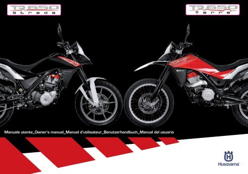
<strong>Manuale</strong> <strong>utente</strong>_Owner’s <strong>manual</strong>_<strong>Manuel</strong> d’utilisateur_Benutzerhandbuch_Manual del usuario
HUSQVARNA MOTORCYCLES S.R.L. declina qualsiasi responsabilità per eventuali erroriin cui può essere incorsa nella compilazione del presente <strong>manual</strong>e e si riserva il diritto di apportarequalsiasi modifica richiesta dallo sviluppo evolutivo dei propri prodotti. Le illustrazioniriportate sono indicative e potrebbero non corrispondere esattamente al particolare trattato.É vietatala riproduzione anche parziale della presente pubblicazione senza autorizzazionescritta.To the best knowledge of HUSQVARNA MOTORCYCLES S.R.L. the material containedherein is accurate as of the date this pubblication was approved for printing. HUSQVARNAMOTORCYCLES S.R.L. reserves the right to change specifications, equipment, or designs atany time without notice and without incurring obligation. Illustrations in this <strong>manual</strong> are merelyfor demonstration purposes and could not exactly match the detail described. No part of this<strong>manual</strong> can be reproduced without permission in writing of the copyright holder.HUSQVARNA MOTORCYCLES S.R.L. décline toute résponsabilité pour erreurs évuntuellescommises pendant la rédaction du manuel et question et se réserve le droit d’apporter tous lesperfectionnements nécessaires sans avis préalable. Les illustrations gravées dans ce manuelne sont qu’à titre idicatif et pourraient ne pas correspondre au détail traité. Le copiage partielou totale de ce manuel sans autorisation écrite est strictement interdit.Die HUSQVARNA MOTORCYCLES S.R.L. lehnt jegliche Verantwortung für eventuelleFehler ab, welche bei der Zusammenstellung dieses Handbuches entstanden sein könnenund behält sichferner das Recht vor, alles, was sich an Änderungen durch die Weiterentwicklungihrer Produkte ergeben sollte, in diesem Hendbuch anzuführen. Die wiedergegebenenDarstellungen sind indikativ und Könnten nicht genau dem betreffenden Teil entsprechen.Die Reproduktion, auch teilweise, der vorliegenden Harausgabe ohne vorheriger schriftlicherGenehmigung ist untersagt.HUSQVARNA MOTORCYCLES S.R.L. no se responsabiliza por los errores debidos a lacompilación del presente <strong>manual</strong> y se reserva el derecho de aportar toda modificación necesariapara el desarrollo evolutivo de sus productos. Las ilustraciones presentadas sonindicativas y pueden no corresponderse exactamente con la pieza tratada. Se prohibe lareproducción, también parciel, de la presente publicación sin autorización por escrito.
ITTR 650 TERRA MY13TR 650 STRADA MY13Ed. 07-2012 - Rev. 02Dove non diversamente specificato, i dati e le prescrizioni si riferiscono a tutti i modelli.CARATTERISTICHE - USO - MANUTENZIONEIT - 1
SOMMARIOPag.PRESENTAZIONE...........................................................3AVVERTENZE IMPORTANTI.............................................3DEFINIZIONE DI IMPIEGO..............................................4AVVERTENZE GENERALI.................................................4DATI PER L’IDENTIFICAZIONE.........................................7DATI TECNICI................................................................8TABELLA DI LUBRIFICAZIONE, RIFORNIMENTI.................9VISTA GENERALE MOTO...............................................10COMANDI...................................................................12STRUMENTO COMBINATO............................................13ISTRUZIONI PER L’USO DEL MOTOCICLO............................20FUSIBILI.....................................................................42APPENDICE.................................................................43OPERAZIONI DI PRECONSEGNA....................................45INDICE ALFABETICO.....................................................46MANUTENZIONE PERIODICA....................... APPENDICE ANotel Le indicazioni di destra e sinistra si riferiscono ai duelati del motociclo rispetto al senso di marcia.l Z:n° dentil A: AustriaAUS: AustraliaB: BelgioBR: BrasileCDN: CanadaCH: SvizzeraD: GermaniaE: SpagnaF: FranciaFIN: FinlandiaGB: Gran BretagnaI: ItaliaJ: GiapponeUSA: Stati Uniti d’Americal Dove non diversamente specificato, i dati e le prescrizionisi riferiscono a tutte le Nazioni.IT - 2CARATTERISTICHE - USO - MANUTENZIONE
PRESENTAZIONEBenvenuti nella famiglia motociclistica <strong>Husqvarna</strong>!La Vostra nuova motocicletta <strong>Husqvarna</strong> é stata progettatae costruita per essere la migliore della suacategoria. Le istruzioni di questo <strong>manual</strong>e sono statepreparate per fornire una guida semplice e chiara allamanutenzione del motociclo. Per ottenere da esso lemigliori prestazioni, si raccomanda di seguire attentamentequanto riportato su questo <strong>manual</strong>e. In esso sonoracchiuse le istruzioni per effettuare le necessarie operazionidi manutenzione. Le riparazioni o le manutenzionipiù specifiche o di maggiore entità richiedono il lavorodi meccanici esperti e l’uso di apposite attrezzature. IlVostro Concessionario <strong>Husqvarna</strong> ha i ricambi originali,l’esperienza e tutte le attrezzature necessarie per renderViun ottimo servizio.Ricordare infine che il “<strong>Manuale</strong> di usoe manutenzione” deve considerarsiparte integrante del motociclo e cometale rimanere allegato allo stesso anchein caso di rivendita.Questo motociclo utilizza componenti progettati e realizzatigrazie a sistemi e tecnologie d’avanguardia esperimentati nelle competizioni.Nelle motociclette da competizione ogni particolare éverificato dopo ogni gara al fine di garantire sempre lemigliori prestazioni.Per il corretto funzionamento del motociclo é necessarioattenersi alla tabella di controllo e manutenzione riportatanell’appendice A.AVVERTENZE IMPORTANTI1) I modelli TR650 STRADA e TR 650 TERRAsono motocicli per impiego STRADALE garantiti esenti dadifetti e coperti da garanzia legale, a condizione che VEN-GA MANTENUTA LA CONFIGURAZIONE DI SERIE e rispettatala tabella di manutenzione riportata nell’appendice A.2) I motocicli partecipanti a competizionidi qualunque genere sono esclusi daogni garanzia, in tutte le loro parti.ITCARATTERISTICHE - USO - MANUTENZIONEIT - 3
IMPORTANTEPer mantenere la “Garanzia di Funzionamento”del veicolo, il Cliente deveseguire il programma di manutenzioneindicato sul libretto di uso e manutenzioneeseguendo i tagliandi presso leofficine autorizzate HUSQVARNA.Il costo per la sostituzione dei pezzi eper la manodopera necessaria per rispettareil piano di manutenzione è acarico del Cliente.NOTA: la garanzia DECADE in caso di noleggiodel motociclo.ATTENZIONE*:Ricordare SEMPRE che i motocicli partecipantia competizioni di qualunque generesono esclusi da OGNI GARANZIA, intutte le loro parti e che modifiche allaconfigurazione di serie comportano laNON CONFORMITÀ DEL VEICOLO AL TIPOOMOLOGATO rendendolo non idoneo allacircolazione su strade pubbliche e quindiutilizzabile solo in “CIRCUITI CHIUSI”da parte di soggetto in possesso dellenecessarie autorizzazioni/ abilitazionidi guida.Premessa importanteLeggere attentamente il presente <strong>manual</strong>e prestandoparticolare attenzione alle note precedute dalle seguentiavvertenze:IT - 4ATTENZIONE*:l Parcheggiare il veicolo dove non possaessere facilmente urtato o danneggiato.CARATTERISTICHE - USO - MANUTENZIONEATTENZIONE*:Indica la possibilità di subire gravi lesionipersonali fino al rischio di decessoin caso di inosservanza delle istruzioni.AVVERTENZA*:Indica la possibilità di subire lesionipersonali o provocare danni al veicoloin caso di inosservanza delle istruzioni.Nota*:Fornisce ulteriori utili informazioni.Sostituzione dei particolariIn caso di sostituzione dei particolari, usare unicamenteparticolari ORIGINALI <strong>Husqvarna</strong>.ATTENZIONE*: Dopo una caduta ispezionareattentamente il motociclo. Assicurarsiche il comando del gas, i freni, lafrizione e tutti gli altri principali comandie componenti non siano stati danneggiati.Guidare un motociclo danneggiatopuò provocare gravi incidenti.ATTENZIONE*: Non avviare o operaresul motociclo senza aver indossato unadeguato abbigliamento protettivo. Indossaresempre casco, stivali, guanti,occhiali protettivi ed altro abbigliamentoappropriato.PRECAUZIONI PER I BAMBINIUrti anche involontari possono provocarela caduta del veicolo con conseguentepericolo per le persone, inmodo particolare per i bambini.l Per evitare cadute accidentali del veicolo,non parcheggiarlo mai su terrenomolle o irregolare né sull’asfaltoreso rovente dal sole.l Poiché il motore e l’impianto di scaricopossono divenire molto caldi,parcheggiare la motocicletta in luoghidove i pedoni o i bambini non possanofacilmente toccarli.l Non lasciare il veicolo incustodito conil motore acceso o la chiave inseritanel commutatore di accensione.DEFINIZIONE DI IMPIEGOQuesta moto è stata costruita in modo da resistere allenormali sollecitazioni dell’impiego stradale.AVVERTENZE GENERALILeggere attentamente le presenti avvertenze generaliprima di utilizzare il veicolo.Borse e baulettiATTENZIONE*:Il sovraccarico ed il carico non uniformepossono pregiudicare la stabilità dimarcia della moto.Non superare il peso totale ammesso eprestare attenzione alle avvertenze sulcarico.- Adattare la regolazione del precarico molle, dell'ammortizzatoree della pressione di gonfiaggio degli
pneumatici al peso totale.- Verificare che il peso sia ripartito uniformemente asinistra e a destra.- Gli oggetti più pesanti devono essere sistemati inbasso e all'interno.- Prestare attenzione al carico massimo e alla velocitàmassima, riportati sulla targhetta di avvertenza delleborse.- Prestare attenzione al carico massimo e alla velocitàmassima, riportati sulla targhetta di avvertenza delbauletto.Immobilizzatore elettronicoL'elettronica della moto rileva, tramite un'antenna adanello posizionata nell'interruttore di accensione, idati registrati nella chiave del veicolo. Solo se la chiaveviene riconosciuta, la centralina consente di avviareil motore.- Custodire la chiave di riserva sempre separatamentedalla chiave di accensione.- Chiavi di riserva e chiavi di accensione sono reperibilisolo presso i concessionari HUSQVARNA. Ilconcessionario sarà tenuto a verificare la legittimitàdell'acquisto, poiché le chiavi fanno parte di un sistemadi sicurezza.Monossido di carbonioFar funzionare il motore esclusivamente in un luogo apertoo in un locale ben ventilato. Se si opera in spazi chiusi utilizzareun'adeguato sistema di aspirazione fumi.ATTENZIONE*:I fumi di scarico contengono monossidodi carbonio che, se inalato, può provocarela perdita di conoscenza e anche lamorte.Parti del veicolo che si riscaldanoPrima di operare sul motore e sul gruppo di scaricoattendere che si raffreddino; questi componenti, duranteil funzionamento del veicolo si riscaldano moltoe rimangono caldi per un certo periodo dopo lo spegnimentodel motore.AVVERTENZA*:Pericolo di scottature, operare con cautelase necessario utilizzare adeguatimezzi di protezione individuale.CombustibileATTENZIONE*:Il carburante utilizzato per la propulsionedei motori a scoppio è altamenteinfiammabile ed esplosivo.Effettuare il rifornimento con il motorespento e in zone ventilate; nonfumare, evitare il contatto tra il carburantee fiamme libere, scintille ecc.potrebbero causarne l'esplosione.Non disperdere il carburante nell'ambiente.Tenere lontano dalla portata dei bambini.AVVERTENZA*:Non inclinare eccessivamente il veicolopotrebbe verificarsi una fuoriuscitadi carburante.Liquido refrigeranteIl liquido refrigerante in alcuni casi può diventare infiammabile,bruciando produce una fiamma invisibileche tuttavia causa ustioni.ATTENZIONE*:Non versare liquido refrigerante sulleparti calde come motore tubo di scaricoecc.. potrebbe incendiarsi.Durante le operazioni di manutenzioneutilizzare guanti in lattice.Non lasciare mai il liquido refrigerantein contenitori aperti e in posizioni accessibilisia per bambini che animali inquanto è tossico.Con motore caldo NON rimuovere il tappodel radiatore; il liquido è sotto pressionee potrebbe causare bruciature.Olio motoreAVVERTENZA*:Non disperdere l'olio nell'ambiente èaltamente inquinante.Tenere lontano dalla portata dei bambini.Utilizzare guanti in lattice, il contattoprolungato con la pelle può causare seridanni.Conferire l'olio usato in appositi centridi recupero autorizzati come previstodalle norme in vigore nel paese di utilizzodel veicolo.CARATTERISTICHE - USO - MANUTENZIONEIT - 5IT
DATI PER L’IDENTIFICAZIONEIl numero di identificazione del motore è stampigliatosulla parte inferiore destra del carter motore, mentreil numero di matricola del motociclo è stampigliato sulcannotto di sterzo del telaio.Riferite sempre, annotandolo anche sul presente libretto,il numero stampigliato sul telaio quandoordinate i ricambi o chiedete informazioni sul vostromotociclo.TERRA USAZKH0H12A#DV000001(l) (▲) (♦)STRADA USA1ITNUMERO TELAIOZKH0H12B#DV000001(l) (▲) (♦)NUMERO DI IDENTIFICAZIONE DEL MOTOCICLOIl numero di serie composto da 17 caratteri si trova sul latodestro del cannotto di sterzo.(l) = Tipo modello(▲) = Anno modello (2013)(♦) = N° progressivo2(■)ZKH0H11A#DV000001Versione(■)AModelloTR 650 Terra (43 kW)1. Matricola telaio2. Matricola motore(l) (▲) (♦)CDTR 650 Terra (43 kW - ABS)TR 650 Terra (35 kW - ABS)ETR 650 Strada (43 kW - ABS)FTR 650 Strada (35 kW - ABS)CARATTERISTICHE - USO - MANUTENZIONEIT - 7
DATI TECNICIMOTOREMonocilindrico a 4 tempi e quattro valvoleRaffreddamento ......... a liquido ed elettroventolaAlesaggio ............................mm 100Corsa ................................mm 83Cilindrata ............................ cm 3 652Rapporto di compressione .................12,3:1Avviamento .......................... elettricoTipo di combustibile ....benzina verde senza piombo95ROZ/RONDISTRIBUZIONEDoppio albero a camme in testa; comandato da catena;4 valvoleGioco valvole (a motore freddo)Aspirazione .....................0,23 ÷ 0,28 mmScarico ........................0,38 ÷ 0,43 mmLUBRIFICAZIONEA carter secco con serbatoio integrato nel telaio, filtroolio a cartuccia.ACCENSIONEElettronica con anticipo variabile a controllo digitaleTipo candela .................“NGK” MAR9A-J-G06Distanza elettrodi candela .......0,6 mm (± 0,1 mm)ALIMENTAZIONEAd iniezione elettronicaTRASMISSIONE PRIMARIAIngranaggio conduttore su albero motore .......Z 37Ingranaggio condotto su campana frizione ......Z 72Rapporto di trasmissione ..................1,946FRIZIONEMultidisco in bagno d’olio con comando meccanicoCAMBIO VELOCITÁA innesti frontali sempre in presaRapporti di trasmissione1a velocità ......................2,750 (33/12)2a velocità ......................1,750 (28/16)3a velocità ......................1,313 (21/16)4a velocità ......................1,045 (23/22)5a velocità ......................0,875 (21/24)TRASMISSIONE SECONDARIAPignone uscita cambio .....................Z 16Corona sulla ruota. . . . . . . . . . . . . . . . . . . . . . . . . Z 47Rapporto di trasmissione ...................2,938Dimensioni catena di trasmissione . 520KR0 112 maglieRAPPORTI TOTALI DI TRASMISSIONEin 1a velocità ..........................15,722in 2a velocità ..........................10,005in 3a velocità ...........................7,506in 4a velocità ...........................5,974in 5a velocità ...........................2,898TELAIOMonotrave, in tubi a sezione circolare, rettangolare, ellissoidale,in acciaio; telaietto posteriore in acciaioSOSPENSIONE ANTERIORETipo forcella teleidraulica a steli rovesciati...........................steli ø 46 mmEscursione ruota . ......................190 mmSOSPENSIONE POSTERIOREMonoammortizzatore idraulico (regolazione del precaricomolla e freno idraulico di estensione)Escursione ruota . ......................190 mmFRENO ANTERIOREA disco fisso Ø 300 mm con comando idraulico e pinzaflottanteFRENO POSTERIOREA disco flottante Ø240 mm con comando idraulico e pinzaflottanteRUOTETR 650 STRADAAnteriore ................in lega leggera: 2,5”x19”Posteriore ............... in lega leggera: 3”x17”TR 650 TERRAAnteriore .. a raggi con cerchio in alluminio: 1,85”x21”Posteriore. . . . .a raggi con cerchio in alluminio: 3”x18” (no ABS). . . . . . .a raggi con cerchio in alluminio: 3”x17” ( ABS)IT - 8CARATTERISTICHE - USO - MANUTENZIONE
PNEUMATICITR 650 STRADAAnteriore .................110/80 R19” M/C 59 VPosteriore ................140/80 R17” M/C 59 VPressione di gonfiaggio a freddo (solo pilota)Anteriore ..................2,2 kg/cm 2 (31.29 psi)Posteriore .................2,0 kg/cm 2 (28.45 psi)Pressione di gonfiaggio a freddo (pilota e passeggero)Anteriore ..................2,2 kg/cm 2 (31.29 psi)Posteriore .................2,5 kg/cm 2 (35.56 psi)TR 650 TERRAAnteriore ............90/90 21” M/C 54 H TL (ABS)90/90 21” M/C 54 S (no ABS)Posteriore ............140/80 17” M/C 59 H (ABS)140/80 18” M/C 70 S (no ABS)Pressione di gonfiaggio a freddo (solo pilota)Anteriore ..................2,0 kg/cm 2 (28.45 psi)Posteriore .................2,5 kg/cm 2 (35.56 psi)Pressione di gonfiaggio a freddo (pilota e passeggero)Anteriore ..................2,0 kg/cm 2 (28.45 psi)Posteriore .................2,8 kg/cm 2 (39.82 psi)Peso, senza carburante (STRADA). ...........kg 177Peso, senza carburante. (TERRA) ............kg 174Capacità serbatoio carburante compresa la riserva ...l 14Riserva carburante ....................circa l 2,5Capacità circuito di raffreddamento ..........l 1,160Sostituzione olio e filtro ....................l 2,0Rabbocco olio tra livello minimo e livello massimo . l 0,25TABELLA DI LUBRIFICAZIONE, RIFORNIMENTIOlio lubrificazione motore, cambio, trasmissione primaria..............CASTROL POWER1 RACING SAE 10W-50Liquido refrigerante motore ..CASTROL MOTORCYCLE COOLANTLiquido impianti frenanti ..CASTROL RESPONSE SUPER DOT 4Lubrificazione a grasso ......... CASTROL LM GREASE 2Lubrificazione catena trasmissione secondaria............... CASTROL CHAIN LUBE RACINGProtettivo contatti elettrici............. CASTROL METAL PARTS CLEANERITDIMENSIONI, PESO, CAPACITÀInterasse ...........................mm 1500Lunghezza totale (STRADA) .............mm 2248Lunghezza totale (TERRA) ...............mm 2267Larghezza massima ....................mm 885Altezza massima (STRADA) ..............mm 1205Altezza massima (TERRA) ...............mm 1223Altezza sella (STRADA) ..................mm 860Altezza sella (TERRA) ........mm 875 (no ABS - 18”)mm 865 (ABS - 17”)Altezza minima da terra (STRADA) .........mm 250Altezza minima da terra (TERRA).mm 266 (no ABS 18”)mm 257 (ABS 17”)CARATTERISTICHE - USO - MANUTENZIONEIT - 9
VISTA GENERALE MOTO1971381116141221181715109226203234N54321215IT - 10CARATTERISTICHE - USO - MANUTENZIONE
LEGENDA1. Ruota anteriore2. Disco freno anteriore3. Pinza freno anteriore4. Forcella anteriore5. Pedale comando cambio (si innesta la prima marciaspingendo in basso la leva; per tutte le altremarce spingerla in alto. La posizione di “folle” sitrova tra la prima e la seconda marcia)6. Cavalletto laterale7. Corona8. Ruota posteriore9. Portatarga10. Indicatori di direzione posteriori11. Fanale posteriore12. Sella13. Specchietti retrovisori14. Indicatori di direzione anteriori15. Fanale anteriore16. Pedale comando freno posteriore17. Pompa freno posteriore18. Disco freno posteriore19. Pinza freno posteriore20. Pedane passeggero21. Maniglie passeggero22. Silenziatori di scarico23. Radiatore24. Tappo serbatoio carburante25. Strumento digitale26. Interruttore di accensione27. Commutatore destro28. Pulsante ENGINE STOP (arresto di emergenza del ..motore)29. Pulsante avviamento motore30. Leva comando freno anteriore31. Manopola comando gas32. Leva comando frizione33. Commutatore sinistro34. Commutatore ABS (ove previsto)2526242829323127303334ITCARATTERISTICHE - USO - MANUTENZIONEIT - 11
COMANDIRIFORNIMENTO DI CARBURANTEUtilizzare esclusivamente benzina SENZA PIOMBO a 95ottani o superiore.AVVERTENZA*:L'utilizzo di benzina con piombo causadanni irreversibili al catalizzatore cheperde la sua efficacia.ATTENZIONE*:La benzina è estremamente infiammabilee può diventare esplosiva in particolaricondizioni. Spegnere sempre ilmotore, non fumare o avvicinare fiammeo scintille nell’area dove si effettuail rifornimento o si conserva il carburante.ATTENZIONE*:Non riempire il serbatoio oltre il limiteinferiore del bocchettone di carico. Dopoil rifornimento, accertarsi della correttachiusura del tappo (3) del serbatoio.- Sollevare la linguetta (1), introdurre la chiave (2),ruotarla in senso antiorario e rimuovere il tappo serbatoio(3).- Introdurre completamente l'erogatore (4) dellapompa benzina nel serbatoio prima di effettuare ilrifornimento (vedi figura).- Effettuato il rifornimento rimontare il tappo (3)agendo in senso inverso allo smontaggio.3241CAVALLETTO LATERALEOgni motociclo è fornito di un cavalletto laterale (1).Per abbassarlo agire con il piede sull’appiglio (2).ATTENZIONE*:Il cavalletto è progettato per supportareil SOLO PESO DEL MOTOCICLO. Non sedersisul veicolo utilizzando il cavallettocome supporto; potrebbero verificarsidelle rotture con conseguenti gravi lesionipersonali.ATTENZIONE*:Il cavalletto non è dotato di ritorno automatico.Il cavalletto è dotato di un'interruttorerotativo che spegne il motore nel caso siinserisca una marcia con il cavalletto inposizione abbassata.Controllare periodicamente il cavalletto laterale (vedi“Scheda di manutenzione periodica”); verificare che lemolle non siano danneggiate e che il cavalletto si muovaliberamente. Nel caso il cavalletto fosse rumoroso, lubrificaree controllare il perno (A) di fissaggio.21AIT - 12CARATTERISTICHE - USO - MANUTENZIONE
STRUMENTO COMBINATOITIl motociclo è equipaggiato con uno strumento combinatosuddiviso nelle seguenti zone:1. Spie di segnalazione (vedi “ Descrizione spie disegnalazione”).2. Display multifunzione (vedi “ Descrizione displaymultifunzione”).3. ContagiriIndica il numero di giri del motore.4. Spia sistema antifurto (optional)(colore ROSSO).5. Tasto “MODE”6. Tasto “SET”Permette di visualizzare le varie funzioni deldisplay multifunzione vedi “ Descrizione displaymultifunzione”.7. Tasto “LAMPEGGIO EMERGENZA (HAZARD)”Premuto si illuminano lampeggiando contemporaneamentegli indicatori di direzione, la spiae la spia .Ripremere per disattivare il lampeggio di emergenza.5167432CARATTERISTICHE - USO - MANUTENZIONEIT - 13
DESCRIZIONE SPIE DI SEGNALAZIONEABS Spia "ABS"Portando la chiave in posizione "ON" la spialampeggia, e continua a lampeggiare, fino ache il veicolo inizia a muoversi in avanti. Se ilsistema funziona correttamente la spia si spegne;se l'autodiagnosi del sistema verifica unaanomalia, o se il sistema viene disattivato, laspia rimane accesa.IT - 14Spia indicatori di direzione (colore VERDE)Si illumina lampeggiando quando sono inseritigi indicatori di direzione o è stato premuto iltasto “HAZARD”.Spia abbagliante (colore BLU)Si illumina fissa quando si inserisce la luce abbagliante.Spia folle (colore VERDE)Si illumina fissa quando è inserita la marciafolle.Spia Engine Diagnosi (colore ARANCIO)Si illumina fissa quando la centralina del motoreha diagnosticato una anomalia di funzionamento.Esistono due stati di anomalia:- Anomalia grave: il motore si spegne ed ènecessario rivolgersi ad un concessionarioHUSQVARNA.- Anomalia con funzionamento di emergenza:il motore funziona con prestazioniridotte in modo da potersi recare presso ilpiù vicino concessionario HUSQVARNA per ilcontrollo dell’anomalia.1 2 3CARATTERISTICHE - USO - MANUTENZIONESpia “HAZARD” (colore ROSSO)Si illumina lampeggiando in contemporaneacon la spia e con gli indicatori di direzionequando è stato premuto l’interruttore .Spia riserva carburante (colore ARANCIO)Si illumina quando il livello del carburante haraggiunto un livello tale, per cui nel serbatoiosono rimasti circa 3 litri di carburante.E’ necessario effettuare il rifornimento.Nota *:La spia riserva carburante normalmente si spegnequalche tempo dopo aver effettuato il rifornimento.7456DESCRIZIONE DISPLAY MULTIFUNZIONE1. Indicatore “ICE”:Appare quando la temperatura esterna è inferiorea 3°C o 37,4°F2. Indicatore “SERVICE”:Appare indicando il raggiungimento dell’intervallodi manutenzione.Rivolgersi al concessionario HUSQVARNA per leoperazioni di manutenzione periodica.3. Indicazione scala contachilometri km/h o mp/h(vedi “impostazione unità di misura”)4. Indicatore di velocità5. Parametri di visualizzazione:In questo campo si possono impostare singolarmentei seguenti parametri che verranno visualizzatinel campo 6.ODO = Contachilometri / Contamiglia totaleTRIP = Contachilometri / Contamiglia parziale(per impostare la funzione vedi “Impostazioneparametri”)TEMP = Temperatura aria (AIR BOX) / Temperaturaliquido di raffreddamentoCON = Consumo effettivo di carburante / Consumomedio.CLOCK = Orologio ( Vedi “Regolazione orologio”).6. Visualizza il valore del parametro impostato nelcampo (5).7. Si illumina in sequenza da sinistra verso destracon l’aumento della temperatura del liquido diraffreddamento.In caso di sovratemperatura, la spia si illuminafissa e la barra (7) lampeggia.
REGOLAZIONE OROLOGIOL’impostazione dell’orologio deve essere effettuata conmoto ferma e chiave in posizione ON.L’impostazione dell’orologio è 24 ore.- Premere il tasto “S” (1) fino a visualizzare la scritta“CLOCK” sul display.oppure dopo 10 secondi l’impostazione viene memorizzataautomaticamente.IMPOSTAZIONE UNITÀ DI MISURAL’impostazione delle unità di misura deve essere effettuatacon moto ferma e chiave in posizione ON.- Premere il tasto “S” (1) fino a visualizzare la scritta“ODO” o “TEMP” sul display.> 4”IT1> 4”- Premere il tasto “S” per più di 4 secondi, sul displaylampeggiano le ore.- Il valore delle ore aumenta di una unità ad ogni pressionebreve del tasto “S”.- Il valore delle ore diminuisce di una unità ad ogni pressionebreve del tasto “M”.> 4”1- Premere il tasto “S” per più di 4 secondi, sul display sivisualizza la scritta “SET” e sul display appare l’unitàdi misura attualmente in uso.- Premere una volta il tasto “S” per variare l’unità dimisura, scelta l’unità di misura premere il tasto “S”per più di 4 secondi per confermare il dato impostato epassare all’impostazione della scala successiva.> 4”4”
IMPOSTAZIONE PARAMETRICon cruscotto alimentato, premere il tasto “S” (1) pervisualizzare le varie funzioni del display:ODO ; TRIP ; TEMP ; CON ; CLOCKFunzione CON:Con abilitata questa funzione è possibile premendo iltasto “S” per un tempo superiore a 4 secondi azzeraree avviare un nuovo conteggio dei litri / Gall che si consumerannodal momento dell’azzeramento e resettare ilconsumo medio (L/100 Km).1Le funzioni “ODO”, “TEMP”, e “CLOCK” sono solo di visualizzazione.Funzione TRIP:Con abilitata questa funzione, è possibile premendo iltasto “S” per un tempo superiore a 4 secondi, azzerareed avviare un nuovo conteggio parziale dei chilometri /miglia successivamente percorsi.Con questa funzione impostata dopo l’illuminazione dellalampada della riserva carburante e premendo il tasto“S” (1) per un tempo superiore a 4 secondi è possibilevisualizzare il consumo del carburante (in litri o Gallonia seconda dell’unità di misura scelta) dal momento chesi è entrati in riserva in poi.1IT - 16CARATTERISTICHE - USO - MANUTENZIONE
COMANDO GASLa manopola (1) del gas è situata sul lato destro delmanubrio. La posizione del comando sul manubrio puòessere regolata allentando le due viti di fissaggio (2).AVVERTENZA*:Non dimenticare di stringere le viti (2)dopo la regolazione.COMANDO FRENO ANTERIORELa leva (1) del freno è situata sul lato destro del manubrio.La posizione del comando sul manubrio può essereregolata allentando le due viti di fissaggio (2).ATTENZIONE*:A regolazione avvenuta, ruotare il manubrioverso destra fino a finecorsa, econtrollare che la leva non tocchi la carrozzeria.Un interruttore di stop, all'atto della frenata, provocal'accensione della lampada del fanale posteriore.AVVERTENZA*:Non dimenticare di stringere le viti (2)dopo la regolazione.INTERRUTTORE DI ACCENSIONEL’interruttore di accensione consta di tre posizioni:Posizione "OFF":Posizione di estrazione chiave e spegnimento motorePosizione "ON":Dalla posizione OFF ruotare in senso orario la chiave (1)in posizione ON; si avranno inseriti l’accensione, le luci diposizione e gli utilizzatori e si potrà avviare il motociclo;Posizione “ ”:Posizione bloccasterzo (Vedi bloccasterzo)IT211ONOFFPUSH122CARATTERISTICHE - USO - MANUTENZIONEIT - 17
BLOCCASTERZOIl motociclo è fornito di un bloccasterzo posto sul blocchettodi avviamento.Per bloccare lo sterzo, operare nel modo seguente:COMMUTATORE DESTRO SUL MANUBRIOIl commutatore destro ha i seguenti comandi:1) Pulsante avviamento motore2) Interruttore di EMERGENZA arresto motore.5) Avvisatore acustico.- Ruotare il manubrio verso sinistra fino a finecorsa.- Introdurre la chiave nel blocchetto (1), premerela chiave verso il basso e ruotarla dalla posizione“OFF” alla posizione “ ” quindi estrarla.- Per sbloccare lo sterzo agire inversamente al bloccaggio.21COMMUTATORE SINISTRO SUL MANUBRIOIl commutatore sinistro ha i seguenti comandi:1) Flash abbagliante (ritorno automatico).12) Comando selezione luce abbagliante.IT - 181OFFPUSHCARATTERISTICHE - USO - MANUTENZIONEONComando selezione luce anabbagliante.3) Attivazione indicatori di direzione sinistri.Attivazione indicatori di direzione destri.Per disattivare l’indicatore, premere sulla levetta di comandouna volta che è ritornata al centro.4) Commutatore ABS (ove previsto)- Premendo il pulsante per più di 3 secondi si inserisceo si disinserisce il sistema di frenata assistita“ABS”.253ABS4
COMANDO FRIZIONELa leva (1) di comando della frizione è situata sul latosinistro del manubrio.La posizione del comando frizione sul manubrio può essereregolata allentando le viti (2) di fissaggio.ATTENZIONE*:A regolazione avvenuta, ruotare il manubrioverso sinistra fino a finecorsa,e controllare che la leva non tocchi lacarrozzeria.Sul comando frizione è presente un'interruttore di"STOP" che consente l'avviamento della moto con marciainserita e leva della frizione tirata (il cavalletto deveessere in posizione sollevata)AVVERTENZA*:Non dimenticare di stringere le viti (2)dopo la regolazione.COMANDO FRENO POSTERIOREIl pedale (1) di comando del freno posteriore si trova sullato destro del motociclo.Un interruttore di stop, all’atto della frenata, provocal’accensione della lampada del fanale posteriore.COMANDO CAMBIOLa leva (1) è posta sul lato sinistro del motore. Il pilota,ad ogni cambio di velocità, deve lasciare libero il pedaleche tornerà nella sua posizione centrale; la posizione di“folle” (N) si trova tra la prima e la seconda marcia.Si innesta la prima marcia spingendo in basso la leva;per tutte le altre marce spingerla in alto.La posizione della leva (1) sull’albero può essere variata.Per effettuare questa operazione occorre allentare lavite (2), togliere la leva e porla in una nuova posizionesull’albero.Bloccare la vite ad operazione effettuata.ATTENZIONE*: Evitare di inclinare eccessivamentela leva verso il basso!AVVERTENZA*: Non cambiare le marcesenza disinnestare la frizione e chiudereil gas. Il motore potrebbe andare“fuorigiri” e subire danni.ATTENZIONE*: Non rallentare scalando lemarce quando ci si trova ad una velocitàche potrebbe portare il motore “fuorigiri”oppure far perdere aderenza allaruota posteriore, se si selezionasse lamarcia immediatamente inferiore.IT1N321214 5 IT - 1912CARATTERISTICHE - USO - MANUTENZIONE
ISTRUZIONI PER L’USO DEL MOTOCICLONOTA*: Se non avete confidenza colfunzionamento del motociclo, prima diguidarlo, leggete attentamente le istruzionicontenute nel paragrafo “COMAN-DI”.CONTROLLI PRELIMINARIOgniqualvolta si intende usare il motociclo si deve effettuareun controllo generale procedendo alle seguentiverifiche:- controllare il livello del carburante e dell’olio motore;- controllare il livello del fluido freni;- controllare lo sterzo girando il manubrio a fondo corsain entrambi i sensi;- controllare la pressione dei pneumatici e il loro stato diusura;- la tenuta di strada della moto può non essere ottimalegià al raggiungimento della scolpitura minima delbattistrada prescritta per legge. Sostituire i pneumaticiquando si raggiunge la scolpitura minima.- controllare la tensione della catena;- controllare ed eventualmente registrare il comandogas;- ruotare la chiave dell’interruttore di accensione in posizioneON: verificare l’illuminazione del display dellostrumento;- verificare l'accensione delle luci di posizione, anabbagliante,abbagliante e l'accensione della relativa spia;- azionare gli indicatori di direzione, e verificare l’accensionedella spia;- verificare l’accensione della luce dello stop posteriore.IT - 20CARATTERISTICHE - USO - MANUTENZIONEIl rodaggio del motore è fondamentale per garantirne lasuccessiva durata ed il corretto funzionamento.Percorrere, se possibile, strade con molte curve e/o collinose,dove il motore, le sospensioni ed i freni vengonosottoposti ad un rodaggio più efficace.Ricordare che anche i pneumatici nuovi hanno la necessitàdi essere rodati per ottenere la massima aderenza;guidare con cautela per i primi 100 km (62,5 mi).Variare la velocità di guida durante il rodaggio.In questo modo si consente di "caricare" il lavoro deicomponenti e successivamente "scaricare", raffreddandole parti del motore.Sebbene sia importante sollecitare i componenti delmotore durante il rodaggio, fare molta attenzione a noneccedere.Soltanto dopo i primi 1000 km (625 mi)di rodaggio è possibile ottenere le miglioriprestazioni in accelerazione delveicolo.Attenersi alle seguenti indicazioni:non accelerare bruscamente e completamente quando ilmotore sta funzionando ad un regime di giri basso, siadurante che dopo il rodaggio.Durante i primi 100 km (62 mi) agire con cautela suifreni, ed evitare brusche e prolungate frenate.Ciò per consentirne un corretto assestamento del materialed'attrito delle pastiglie sui dischi freno.Durante i primi 1000 km (625 mi) di percorrenza, nonsuperare mai 5000 giri/min (rpm) (vedi tabella).Dopo i primi 1000 km (625 mi) di funzionamento,eseguire i controlli previstinella scheda di manutenzione periodica,al fine di evitare danni a sé stessi,agli altri e/o al veicolo.Dopo i 1000 km (625 mi) si possono pretendere dal motoremaggiori prestazioni, senza tuttavia fare girare ilmotore oltre il regime di giri massimo consentito.Massimi numeri di giri del motore raccomandati:percorrenza Km (mi) giri/min (rpm)0-1000 (0-625)......................................................5000
INDIVIDUAZIONE DEGLI INCONVENIENTI DI FUNZIONA-MENTOIl seguente elenco di eventuali inconvenienti di funzionamentoserve, in linea generale, per individuarne l’origineed attuarne il rimedio.Rivolgersi comunque ad un concessionario ufficiale <strong>Husqvarna</strong>che ha l'esperienza e le necessarie competenzeper fornirvi tutta l'assistenza di cui potreste avere bisogno.Il motore non si avvia.- Inadeguata tecnica d’avviamento: attenersi a quantoriportato al paragrafo “Avviamento del motore”.- Cavalletto abbassato: sollevare il cavalletto.- Mancanza carburante: effettuare il rifornimento di carburante.- Batteria scarica / difettosa: controllare/caricare la batteria.- Motorino d’avviamento difettoso: riparare o sostituire.- Pulsante d’avviamento difettoso: sostituire il commutatore.Il motore stenta ad avviarsi.- Candela sporca o in cattive condizioni: pulire o sostituire.- Batteria scarica: caricare.Il motore é carente di potenza.- Filtro aria sporco: pulire.- Cambiare la candela.- Gioco valvole non corretto: regolare.- Compressione insufficiente: verificarne la causa.- Corpo farfallato non regolato correttamente: regolare.Il motore batte in testa.- Forte deposito di carbonio sul cielo del pistone o nellacamera di scoppio: pulire.- Candela difettosa o con grado termico errato: sostituire.- Carburante non adeguato; utilizzare solo benzina senzapiombo con 95 ottani o superiore.L’alternatore non carica o carica insufficientemente.- Cavi sul regolatore di tensione mal collegati o in cortocircuito: collegare correttamente o sostituire.- Bobina alternatore difettosa: sostituire.- Rotore smagnetizzato: sostituire.- Regolatore di tensione difettoso: sostituire.La batteria si surriscalda.- Regolatore di tensione difettoso: sostituire.Difficoltà ad innestare le marce.- Frizione non regolata correttamente : regolare la frizione.- Presenza aria nell'impianto: spurgare l'aria.- Livello olio basso: ripristinare il livello.ITIl motore si surriscalda.- Ostruzioni al flusso d’aria sul radiatore: pulire.- Ventola di raffreddamento non parte: controllare/sostituireil termointerruttore.- Ventola difettosa: sostituire.- Insufficiente quantità di liquido nel radiatore: rabboccare.- Insufficiente quantità di olio: rabboccare.La frizione slitta.- Carico molle insufficiente: sostituire.- Dischi frizione consumati: sostituire.I freni non funzionano adeguatamente.- Pastiglie consumate: sostituire.CARATTERISTICHE - USO - MANUTENZIONEIT - 21
SALITA /DISCESA PILOTA E PASSEGGERONorme generaliLeggere attentamente le indicazioni riportate di seguitoin quanto forniscono informazioni importanti al finedella sicurezza del pilota e del passeggero e per evitaredanni a cose al motociclo.La salita e la discesa dal motociclo deve essere effettuatasempre dalla parte sinistra della moto, con le mani libere,senza impedimenti e con cavalletto abbassato.Il pilota deve essere il primo a salire e l'ultimo a scenderedal motoveicolo e deve governare la stabilità della motodurante la salita e la discesa del passeggero.Non scendere dal veicolo saltando o allungando la gamba,scendere sempre eseguendo le operazioni descrittenel relativo paragrafo.Salita del pilotaCon moto posizionata sul cavalletto laterale effettuare leseguenti operazioni:- Dalla parte sinistra impugnare correttamente con entrambele mani il manubrio quindi sollevare la gambadestra e oltrepassare la sella.- Sedersi sulla moto e appoggiare entrambe i piedi aterra raddrizzando il veicolo senza caricare il propriopeso sul cavalletto laterale.AVVERTENZA*:Nel caso non si riesca ad appoggiareentrambe i piedi a terra appoggiare ilpiede destro tenendo il sinistro prontoall'appoggio.- Avviare la moto come descritto nel relativo paragrafo.- Con il piede sinistro fare rientrare completamente ilcavalletto.Salita del passeggeroSalire prima il pilota come descritto nel relativo paragrafosenza avviare la moto.- Fare estrarre dal passeggero le pedane (1) poggiapiediAVVERTENZA*:Il pilota nella posizione di guida nondeve assolutamente estrarre o tentaredi estrarre i poggiapiedi posteriori delpasseggero, potrebbe comprometterel'equilibrio del veicolo.1IT - 22CARATTERISTICHE - USO - MANUTENZIONE
Appoggiare la mano sinistra sulla spalla del pilota, ilpiede sinistro sulla pedana appoggiapiedi quindi saliresulla moto sollevando la gamba destra muovendosicon cautela per non sbilanciare il veicolo e il pilota.- Con le mani tenersi alle apposite maniglie (2).- Avviare la moto come descritto nel relativo paragrafo- Con il piede sinistro fare rientrare completamente ilcavalletto.Discesa dalla moto- Arrestare il veicolo e spegnere il motore.AVVERTENZA*:Accertarsi che la zona dove si deve parcheggiareil veicolo sia stabile e in piano.- Appoggiare entrambe i piedi a terra.- Con il piede sinistro estrarre completamente il cavalletto.- Scendere prima il passeggero dalla parte sinistra delveicolo appoggiando il piede sulla pedana sinistra esollevando la gamba destra.- Inclinare la moto verso sinistra fino ad appoggiarla sulcavalletto.- Spegnere la moto come descritto nel relativo paragrafo- Con le mani ben salde sul manubrio scendere dallamoto dalla parte sinistra sollevando la gamba destra.IT2CARATTERISTICHE - USO - MANUTENZIONEIT - 23
AVVIAMENTO DEL MOTOREON1) Porre la chiave (1) dell’interruttore accensione inposizione ON e attendere la fine del CHECK dellostrumento;2) tirare la leva (2) della frizione;3) mettere il pedale (3) del cambio in folle;4) controllare che il comando gas (4) sia completamentechiuso.Nota*:L’unità di controllo del motore è dotatadi strategia di avviamento cheentra in funzione solo se il comandogas è completamente chiuso.5) Controllare che il pulsante (5) sia in posizioneestratta, quindi premere il pulsante avviamento(6).6) Rilasciare la leva (2) della frizione.1OFFPUSHN3Nota *:Sul supporto della leva frizione è montato un interruttoredi sicurezza che consente di effettuare l’avviamentoSOLO con il cambio in folle o con la marcia inserita e laleva frizione tirata.24Sul cavalletto laterale è presente un interruttore che spegneil motore al rilascio della frizione con marcia inseritae cavalletto laterale abbassato.IMPORTANTENON ESEGUIRE MAI L’AVVIAMENTO SENEL CIRCUITO NON È INSERITA LA BAT-TERIA.NOTA IMPORTANTE IN CASO DI AVVIAMENTO A FREDDO ABASSE TEMPERATURESi raccomanda di effettuare un breve riscaldamentoal minimo.In tale modo l’olio, circolando, raggiungerà tutti i puntiche richiedono lubrificazione ed il liquido refrigerantearriverà alla temperatura necessaria al correttofunzionamento del motore.Evitare di effettuare un riscaldamento troppo prolungatodel motore.65IT - 24CARATTERISTICHE - USO - MANUTENZIONE
GUIDA DELLA MOTOATTENZIONE*:Prima della partenza accertarsi che:- il cavalletto laterale sia completamentesollevato;- in assenza di passeggero le pedaneposteriori siano chiuse;- il passeggero sia correttamente istruitosulle modalità di comportamentodurante il viaggio per evitare difficoltàdurante le manovre.1) Avviare la moto come descritto nel relativo paragrafo.2) Regolare gli specchietti retrovisori in funzione allaposizione di guida in modo da garantire una correttavisibilità.Nota *:Selezionare la marcia più appropriata in funzione allavelocità desiderata; la velocità è proporzionale alla rotazionedella manopola del gas, quindi ruotare la manopoladel gas in modo graduale senza superare il numerodi giri consigliato.5) Per passare alle marce superiori agire come segue:Rilasciare la manopola gas (1), tirare la leva dellafrizione (2), sollevare la leva (3) del cambio e rilasciarela leva (2) della frizione e contemporaneamenteaccelerare.21ITATTENZIONE*:I veicoli visualizzati negli specchiettiretrovisori sembrano più lontani diquanto siano in realtà, questo è dovutoalla particolare forma degli specchiretrovisori; familiarizzare con l'usodegli specchietti per una guida correttae sicura.N32133) Con la manopola (1) del gas chiusa ed il motoreal minimo, tirare la leva (2) della frizione quindispingere verso il basso la leva (3) del cambio perselezionare la prima marcia.4) Rilasciare lentamente la leva (2) della frizione econtemporaneamente accelerare ruotando moderatamentela manopola del gas (1);il veicolo comincerà a muoversi.4 5 IT - 251CARATTERISTICHE - USO - MANUTENZIONE
GUIDA SICURADi seguito elenchiamo alcuni principi di base per unaguida sicura della vostra moto.- RicordateVi che la Vostra sicurezza e la sicurezzadel passeggero viene prima di tutto. Arrivare sanie salvi alla fine del viaggio deve essere l'obbiettivoprincipale.- Il pilota e il passeggero devono indossare adeguatiindumenti di protezione quali tute guanti scarpe cascoadeguati per un uso motociclistico.- La posizione del pilota sulla moto deve essere taleda avere la più ampia visuale possibile della stradache si sta percorrendo.- Guidare la moto con prudenza, impostare la velocitàin funzione al traffico e al tipo di conformazione dellastrada.Una guida fluida permette di valutare i pericoli e diimpostare le traiettorie in curva in modo più preciso.- Prestare sempre attenzione ai cartelli segnaleticie modulate la velocità in funzione alle indicazioniriportate.- Rispettate sempre i limiti di velocità.- Valutate sempre le condizione del fondo stradale emodulate la velocità in funzione dello stesso.- Limitare la velocità in caso di pioggia e soprattuttoin caso di presenza di pozzanghere sull'asfalto.- Quando si procede su superfici bagnate o su superficicon scarsa aderenza (neve, ghiaccio, fango, ecc..)mantenere una velocità moderata evitando frenatebrusche e manovre improvvise.- Mantenere le distanze di sicurezza dai veicoli che Viprecedono.- Prima di effettuare un sorpasso verificare che nonvi siano ostacoli davanti al veicolo che dovete sorpassaree controllate sempre tramite gli specchiettiretrovisori che non vi siano altri veicoli che sopraggiungonoda dietro.- Frenare utilizzando contemporaneamente sia il frenoanteriore che quello posteriore: ciò contribuisce amantenere la stabilità del veicolo.- Rilasciare in modo graduale al frizione quando siscalano le marce.- Se avvertite stanchezza o sonnolenza fermatevi ariposare.- Scalare le marce nei seguenti casi:Nei tratti di discesa e nelle frenate per aumentarel'azione frenante tramite la compressione del motore;l'utilizzo dei soli freni in discesa potrebbe provocareil surriscaldamento delle pastiglie dei frenilimitando l'azione frenante;Nei tratti in salita o in pianura quando la marcia nonè adeguata alla velocità della moto (marcia lunga ebassa velocità);ATTENZIONE*:Scalare una marcia per volta; il passaggioalla marcia inferiore scalandopiù di una marcia per volta potrebbecausare un fuorigiri del motore e/oil blocco della ruota posteriore.- Non spegnere il motore quando si procede in discesa.- Quando viaggiate con il passeggero aumentate ledistanze di sicurezza dai veicoli che Vi precedono etenete conto del suo peso quando frenate e quandodovete effettuare una curva od un sorpasso.- Non utilizzate lacci corde ecc... per fissare il bagaglio,utilizzate solo borse omologate adatte per iltipo di moto che utilizzate.IT - 26CARATTERISTICHE - USO - MANUTENZIONE
ARRESTO DEL MOTOCICLO E DEL MOTORE- Chiudere completamente la manopola (1) del gas inmodo da far decelerare il motociclo.- Frenare sia anteriormente (2) che posteriormente(3) mentre si scalano le marce (per una forte decelerazione,agire in modo deciso contemporaneamentesulla leva del freno anteriore e pedale del frenoposteriore).- Tirare la leva frizione (4) e porre la leva (5) delcambio in posizione di folle, quindi arrestare completamenteil motociclo.3- Ruotare la chiave di avviamento (6) in posizioneOFF (posizione di estrazione chiave) per spegnereil motore.6OFFPUSHONIT4ATTENZIONE*:In alcune condizioni può essere utilel’uso indipendente del freno anterioreo di quello posteriore. Usare il frenoanteriore con prudenza, specialmentesu terreni sdrucciolevoli. L’uso scorrettodei freni può causare gravi incidenti.2N15CARATTERISTICHE - USO - MANUTENZIONEIT - 27
ARRESTO DEL MOTORE IN EMERGENZA- In caso di “EMERGENZA” premere il pulsante rosso(1) per arrestare il motore.1ATTENZIONE*:Utilizzare questo pulsante solo in casodi “EMERGENZA” con estrema cautelasoprattutto con motociclo in velocità.ATTENZIONE*:In caso di bloccaggio del gas in posizioneaperta o di altro malfunzionamento chefacesse girare il motore in modo incontrollabile,tirare IMMEDIATAMENTE la levadella frizione e premere il pulsante arrestomotore.Mantenere il controllo del motociclo con ilnormale uso dei freni e dello sterzo mentresi preme il pulsante di arresto.MARMITTA CATALITICA- Questo motoveicolo è dotato di un impianto di scaricocontenente un catalizzatore; tale dispositivoossida i gas di scarico (monossido di carbonio e gliidrocarburi incombusti) convertendoli in anidridecarbonica e vapore acqueo.AVVERTENZA*:La marmitta catalitica raggiunge, durantel'uso della moto, temperature moltoelevate quindi evitare di parcheggiarela moto in prossimità di sterpaglie secche,pericolo di incendio.AVVERTENZA*:Non modificare e/o rimuovere la marmittacatalitica o componenti di essa; larimozione di tali componenti comportanola NON CONFORMITÀ DEL VEICOLOAL TIPO OMOLOGATO rendendolo nonidoneo alla circolazione su strade pubbliche.- Controllare che l'impianto di scarico non abbia segnidi ruggine o fori e che il sistema di scarico funzionicorrettamente; se il rumore prodotto dal sistema discarico aumenta sensibilmente rivolgersi a un concessionarioufficiale HUSQVARNA.CONTROLLO LIVELLO OLIOIl livello dell’olio deve essere controllato con il veicolo inposizione verticale su terreno piano.- Avviare la moto e riscaldare il motore fino all’avviamentodella ventola di raffreddamento; attendere ulteriori3 minuti quindi spegnere il motore.- Verificare il livello nel seguente modo:- Svitare il tappo (1) con asta graduata (2) e rimuoverlodal telaio.- Pulire l’asta graduata (2) con un panno.- Inserire l’asta graduata (2) nel foro (3) senza avvitareil tappo.- Estrarre l’asta (2) dal foro (3) e verificare che illivello si trovi compreso tra le due tacche MIN eMAX.- Per effettuare l’eventuale rabbocco, introdurre l’olionel foro (3); per il tipo di olio vedi paragrafo “Datitecnici”.AVVERTENZA*:Non superare mai il livello massimo.1MAXMAXMINMIN23IT - 28CARATTERISTICHE - USO - MANUTENZIONE
CONTROLLO FILTRO ARIANota *:Pulire la zona filtro prima di smontare il coperchio.- Svitare le viti (1) e rimuovere il coperchio (2) completodi filtro (3);- rimuovere il filtro (3) e controllare che non sia intasato/sporco;se necessario sostituirlo;AVVERTENZA*:Prima di rimontare il filtro controllareche superfici di contatto del filtro con lacassa filtro e il coperchio siano perfettamentepulite.321- al rimontaggio controllare che filtro (3) sia inseritocorrettamente nell'apposita sede (4).4323IT - 30CARATTERISTICHE - USO - MANUTENZIONE
CONTROLLO LIVELLO FLUIDO FRENO ANTERIOREIl livello del fluido nel serbatoio della pompa non devemai trovarsi al di sotto del valore minimo visibile dall’oblò(1) ricavato lateralmente sul corpo pompa (2).Un eventuale abbassamento del livello del fluido puòpermettere l’ingresso di aria nell’impianto con conseguenteallungamento della corsa della leva.ATTENZIONE*:Se la leva del freno risulta troppo “morbida”,si è in presenza di aria nella tubazioneo di un difetto dell’impianto.Essendo pericoloso guidare il motocicloin queste condizioni, fare immediatamentecontrollare l’impianto frenantepresso il Concessionario <strong>Husqvarna</strong>.AVVERTENZA*:Non versare fluido freni su superfici verniciateo lenti (es. fanali).AVVERTENZA*:Non mischiare due tipi di fluido diversi.Se si sceglie di impiegare una diversamarca di fluido, eliminare completamentequello esistente.AVVERTENZA*:Il fluido freni può causare irritazioni.Evitare il contatto con la pelle e gli occhi.In caso di contatto, pulire completamentela parte colpita e, qualora si trattassedegli occhi, chiamare un medico.2MIN132REGISTRAZIONE CORSA A VUOTO FRENO POSTERIOREIl pedale (1) di comando del freno posteriore, deve avereuna corsa a vuoto (B) pari a 5-10 mm (0,196 - 0,39 in)prima di iniziare l’azione frenante.Qualora ciò non si verificasse, procedere alla registrazionenel modo seguente:- allentare il dado (2);- agire sull’astina comando pompa (3) per aumentare odiminuire la corsa a vuoto;- a operazione effettuata serrare nuovamente il dado(2).ATTENZIONE *:La mancanza della corsa a vuoto prescrittaprovocherà la rapida usura dellepastiglie freno con il conseguente rischiodi arrivare alla TOTALE INEFFICIENZA DELFRENO.1BITCARATTERISTICHE - USO - MANUTENZIONEIT - 31
CONTROLLO LIVELLO FLUIDO FRENO POSTERIOREIl livello del fluido nel serbatoio della pompa non devemai trovarsi al di sotto del valore minimo (1) indicato sulserbatoio trasparente (2).Un eventuale abbassamento del livello del fluido puòpermettere l’ingresso di aria nell’impianto con conseguenteallungamento della corsa del pedale.ATTENZIONE*:Se il pedale del freno risulta troppo“morbido”, si è in presenza di aria nellatubazione o di un difetto dell’impianto.Essendo pericoloso guidare il motocicloin queste condizioni, fare immediatamentecontrollare l’impianto frenantepresso il Concessionario <strong>Husqvarna</strong>.AVVERTENZA*:Non versare fluido freni su superfici verniciateo lenti (es. di fanali)AVVERTENZA*:Non mischiare due tipi di fluido diversi.Se si sceglie di impiegare una diversamarca di fluido, eliminare completamentequello esistente.AVVERTENZA*:Il fluido freni può causare irritazioni.Evitare il contatto con la pelle e gli occhi.In caso di contatto, pulire completamentela parte colpita e, qualora si trattassedegli occhi, chiamare un medico.REGOLAZIONE DISTANZA LEVA COMANDO FRIZIONELa leva (1) può essere regolata su tre posizioni, a secondadella dimensione della mano del pilota.Per regolare la posizione della leva (1) spingerla versol'esterno quindi selezionare la posizione desiderata tramiteil registro (2).1MAXIT - 32MIN12CARATTERISTICHE - USO - MANUTENZIONE2
REGOLAZIONE CORSA A VUOTO LEVA FRIZIONELa corsa a vuoto (A) deve essere pari a 5-10 mm (0,196- 0,39 in).- Spostare il soffietto (1) in gomma;- agire sul registro (2) e il controregistro (3) per ottenerela corsa a vuoto indicata.- al termine dell'operazione assicurarsi che il controregistro(3) sia correttamente serrato quindi riposizionareil soffietto in gomma (1).SOSPENSIONIIl veicolo esce dalla fabbrica con una taratura standarddelle sospensioni anteriore e posteriore, in grado di soddisfarela maggior parte delle esigenze.Sulla forcella anteriore non è possibile effettuare nessunaregolazione, sull'ammortizzatore posteriore è possibileregolare il precarico della molla e il freno idraulicoin estensione.REGISTRAZIONE PRECARICO MOLLA AMMORTIZZATORE- Tramite la chiave in dotazione agire sulla ghiera (1);ruotando verso sinistra "A" il precarico aumenta;ruotando verso destra "B" il precarico diminuisce.ATTENZIONE*: Fare attenzione a non toccareil tubo di scarico caldo quando siregistra l’ammortizzatore.IT1A1321AB1CARATTERISTICHE - USO - MANUTENZIONEIT - 33
REGOLAZIONE FRENO IDRAULICO AMMORTIZZATORE INESTENSIONEL’ammortizzatore è regolabile per la corsa di estensione.B) ESTENSIONE - Taratura standard:- 11 scatti(registro 1)Qualora si dovesse ripristinare la taratura standard,ruotare il registro inferiore (1) in senso orario sino allaposizione di tutto chiuso, quindi tornare indietro degliscatti sopracitati.Per ottenere una frenatura più dolce, ruotare il registroin senso antiorario; agire inversamente per ottenere unafrenatura più dura.1REGOLAZIONE TENSIONE CATENALa catena deve essere controllata, registrata e lubrificatain accordo con la “Tabella di manutenzione”, questo permotivi di sicurezza e per prevenire una usura eccessiva.Se la catena si consuma eccessivamente o risulta nonregistrata correttamente, cioè, se è allentata o eccessivamentetesa, può fuoriuscire dalla corona o rompersi.- Posizionare la moto sul cavalletto laterale in modo chela catena non sia sollecitata e caricata;- in corrispondenza della vite (1) sollevare verso l'alto lacatena (2) e misurare la corsa della catena.- il valore corretto deve essere 45 mm (1.77 in).Se così non risulta agire in questo modo:- accertarsi che la moto sia in posizione verticale su appositocavalletto di sostegno posteriore (optional).- allentare sul lato destro il dado (3) di fissaggio delperno ruota;- allentare i controdadi (4) su entrambi i tendicatena;- agire, sulle viti di registro (5) per ottenere il valoredi tensione corretto controllando che, da ambo i lati, ipattini (6) di centraggio ruota siano posizionati nellastessa posizione della scala graduata ricavata nellesedi dei pattini tendicatena sui bracci forcellone;- effettuata la regolazione serrare i controdadi (4) ed ildado perno ruota (3).Dopo la regolazione, controllare sempre che la distanza"A" sia di 45 mm (1.77 in).63412A45 mm4556IT - 34CARATTERISTICHE - USO - MANUTENZIONE
CONTROLLO USURA CATENA, PIGNONE CORONAControllare che la catena non presenti rulli danneggiati,perni allentati, maglie secche e arruginite e che non siaeccessivamente usurata.Controllare che il pignone e/o la corona non siano eccessivamenteusurati e non abbiano denti mancanti.In caso di sostituzione è necessario sostituire corona pignonee catena contemporaneamente.LUBRIFICAZIONE CATENALubrificare la catena attenendosi alle istruzioni che seguono.AVVERTENZA*:Non usare mai grasso per lubrificare lacatena. Il grasso causa l’accumulo di polveree fango che agiscono come abrasiviprovocando l’usura rapida della catena,del pignone e della corona.AVVERTENZA*:Non lavare la catena con getti d'acquaad alta pressione , non utilizzare detergenticon solventi aggressivi o ad altogrado di infiammabilità.- Dopo avere lavato la catena con specifici detergentiasciugarla e lubrificarla utilizzando idonei lubrificantispray.AVVERTENZA*:Il lubrificante della catena NON devevenire a contatto con il pneumatico o ildisco freno posteriori.PNEUMATICIAbbiate cura di tenere i pneumatici gonfiati sempre allagiusta pressione che deve corrispondere a quella indicatanella tabella “Dati Tecnici” presente nella parte inizialedel <strong>manual</strong>e.La misurazione della pressione deve essere effettuatacon pneumatico freddo, se viene misurata con pneumaticocaldo non è corretta.ATTENZIONE*:La corretta pressione e il corretto statodei pneumatici non solo aumentanoil confort di guida ma evitano perditedi aderenza del veicolo sulla strada conconseguenti sbilanciamenti e possibilicadute.Se i pneumatici sono vecchi, anche senon completamente consumati, devonoessere comunque sostituiti in quanto siinduriscono e possono non garantire piùla corretta aderenza.SISTEMA ABSL’ ABS è un sistema elettro-meccanico di ausilio alla frenata:impedisce il bloccaggio delle ruote in fase di frenata, contribuendoa mantenere la stabilità del veicolo, in presenzadi fondo stradale sdrucciolevole, bagnato, o sporco.In condizioni di scarsa aderenza, il sistema può intervenireallungando lo spazio di frenata (ad es. presenza dipietrisco o fondo sdrucciolevole), ma garantisce in ognicaso lo spazio minimo per quel particolare fondo stradale.Quando, durante la frenata, entra in funzione il sistema,si avvertono delle pulsazioni sulla leva del freno: questasensazione non deve indurre ad allentare la pressionesulla leva, in quanto si annullerebbe l’azione del sistema.Peraltro, la presenza del sistema ABS non deve indurrea comportamenti o a condotte di guida che eccedono leconsuete norme di prudenza.ITCARATTERISTICHE - USO - MANUTENZIONEIT - 35
FRENII principali componenti dei due impianti sono: la pompafreno con relativa leva (anteriormente) o pedale (posteriormente),la tubazione, la pinza ed il disco.2LEGENDA1. Leva comando freno anteriore2. Pompa freno anteriore con serbatoio olio3. Tubazione anteriore4. Pinza freno anteriore5. Disco freno anteriore6. Serbatoio olio freno posteriore7. Tubazione posteriore8. Pinza freno posteriore9. Disco freno posteriore10. Pompa freno posteriore11. Pedale comando freno posteriore12. Ruota fonica anteriore (versione ABS)13. Ruota fonica posteriore11254786133119101154IT - 36CARATTERISTICHE - USO - MANUTENZIONE
CONTROLLO USURA PASTIGLIE FRENIControllo pastiglie pinze anteriori.- Posizionare la moto sul cavalletto.- Controllare visivamente lo stato delle pastiglie freno(1) dalla parte posteriore della pinza;Controllo pastiglie pinza posteriore.- Controllare visivamente lo stato delle pastiglie freno(2) dalla parte posteriore della pinza;USURA PASTIGLIEControllare l’usura delle pastiglie.Il limite di servizio”A” é: 1 mm (0.04 in) .Se detto limite é stato superato, oppure se anche unosolo degli indicatori di usura non è più visibile, sostituirele pastiglie in coppia.IT1 2PULIZIA PASTIGLIEAccertarsi che non ci siano tracce di fluido freni o di oliosulle pastiglie o sui dischi. Pulire le pastiglie o i dischida eventuali tracce di fluido o olio con alcool. Sostituirele pastiglie se non é stato possibile pulirle in modosoddisfacente.A = 1 mmA = 1 mmCARATTERISTICHE - USO - MANUTENZIONEIT - 37
RIMOZIONE SELLAPer rimuovere la sella agire come segue:- Inserire la chiave nella serratura (1) posizionata nellaparte posteriore della moto;- ruotare la chiave in senso orario per sganciare la sella(2), quindi sollevarla e sfilarla verso la parte posterioresganciandola dall'aggancio anteriore.Per rimontare la sella agganciarla anteriormente quindipremere la parte posteriore fino a sentire il "Click" diaggancio.IT - 3812CARATTERISTICHE - USO - MANUTENZIONEBATTERIALa batteria, di tipo sigillato, non necessita di manutenzione.Qualora si riscontrassero perdite di elettrolita oinconvenienti all’impianto elettrico, rivolgetevi al ConcessionarioHUSQVARNA.Nel caso il veicolo debba rimanere inutilizzato per lunghiperiodi, si consiglia di scollegare la batteria dall’impiantoelettrico e conservarla al riparo dall’umidità.- Dopo un uso intensivo della batteria, è consigliabileun ciclo di carica lenta1A per 10 ore per batteria 12V-10Ah.- La ricarica rapida è consigliata solo in situazioni diestrema necessità in quanto si riduce drasticamentela vita degli elementi in piombo.6A per 1 ora per batteria 12V-10Ah.RICARICA BATTERIAPer accedere alla batteria, è necessario:- Accertarsi che l'interruttore d'accensione sia in posizioneOFF e che la chiave di avviamento sia estratta;- togliere la sella come descritto nel relativo paragrafo;- rimuovere per primo il cavo negativo NERO o BLUpoi quello positivo ROSSO (in fase di rimontaggio,collegare per primo il cavo positivo ROSSO poi quellonegativo NERO o BLU);- sganciare l'elastico (1);- estrarre la batteria (2) dal proprio alloggiamento.Verificare, con l’ausilio di un voltmetro, che la tensionedella stessa non sia inferiore a 12.5V.In caso contrario, la batteria necessita di un ciclo di ricarica.Utilizzando un caricabatteria a tensione costante, collegareper primo il cavo positivo ROSSO al morsetto positivodella batteria poi quello negativo NERO o BLU almorsetto negativo della stessa.La tensione di riposo si regola su un valore costante solodopo alcune ore, pertanto si consiglia di NON misurarlasubito dopo aver caricato o scaricato la batteria.Verificare sempre lo stato di carica della batteria prima direinstallarla sul veicolo.La batteria deve essere tenuta pulita ed i terminali ingrassaticon grasso neutro o di vaselina.AVVERTENZA*:La batteria in caso di inutilizzo devecomunque essere ricaricata con ciclo dicarica lenta almeno ogni 3 settimane.ATTENZIONE*:Durante la rimozione della batteria evitareogni contatto tra i poli della batteriae parti metalliche del veicolo (es. telaio)per evitare il rischio di cortocircuiti.21
SOSTITUZIONE LAMPADINE FANALE ANTERIOREPer accedere alle lampadine del proiettore, occorre procederenel modo seguente:- Svitare le viti (1) e rimuovere il cupolino (2);- svitare le due viti (4) laterali di fissaggio fanale;4- scollegare il connettore (6);IT2671- svitare completamente la vite superiore (3) di regolazionefanale;- sfilare il fanale (5) ruotandolo verso il basso (vedi figura);- togliere la cuffia in gomma (7) e sganciare la molletta difermo (8) e rimuovere la lampadina (9);Nota*:La lampada (9) del proiettore anteriore è di tipo alogeno;durante la sostituzione occorre prestare attenzione anon toccare con le mani nude la parte in vetro.5389CARATTERISTICHE - USO - MANUTENZIONEIT - 39
Per sostituire la lampada della luce di posizione agirecome segue:- Sfilare il portalampada (10) e rimuovere la lampadina(11).Effettuata la sostituzione, procedere al rimontaggio agendoinversamente quindi effettuare la regolazione del fascioluminoso come descritto nel relativo paragrafo.SOSTITUZIONE LAMPADINE INDICATORI DI DIREZIONE- Svitare, con un cacciavite a stella, la vite (1);- rimuovere il trasparente (2) e sostituire la lampadina (3)spingendola verso l'interno e ruotandola per estrarla;Effettuata la sostituzione, procedere al rimontaggioagendo inversamente.FANALE POSTERIOREIl fanale posteriore (1) è del tipo a LED; in caso di nonfunzionamento deve essere sostituito.11110213IT - 40CARATTERISTICHE - USO - MANUTENZIONE
SOSTITUZIONE LAMPADA LUCE TARGA- Svitare la vite (1) e staccare la luce targa (2) dal parafango;- estrarre il portalampada (3) con la lampadina (4) dalsuporto;- tirare la lampadina (4) per sfilarla dal portalampada;Effettuata la sostituzione, procedere inversamente per ilrimontaggio.REGOLAZIONE FANALE ANTERIOREPer controllare se il fanale è orientato nel modo correttomettere il motociclo, con in pneumatici gonfiati alla giustapressione e con una persona seduta in sella, perfettamenteperpendicolare con il suo asse longitudinale.Di fronte ad una parete o ad uno schermo, distante daesso 10 metri (32,8 ft), tracciare una linea orizzontalecorrispondente all’altezza del centro del fanale ed unaverticale in linea con l’asse longitudinale del veicolo.L’eventuale rettifica dell’orientamento si può effettuareagendo come segue:- Agire sulla vite (1) di regolazione posta sulla parte superioredel gruppo faro;avvitando il fascio luminoso si alza;svitando il fascio luminoso si abbassa.IT2Effettuare il controllo possibilmente nella penombra.Accendendo la luce abbagliante il limite superiore di demarcazionetra la zona oscura e la zona illuminata deverisultare ad una altezza non superiore a 9/10 dell’altezzada terra del centro del proiettore.1341CARATTERISTICHE - USO - MANUTENZIONEIT - 41
FUSIBILIIn caso di cattivo funzionamento dei fusibili, si potrebberoverificare inconvenienti al motociclo. Per accedere aifusibili procedere nel modo seguente:Fusibile generale (1) - 30ADue fusibili posizionati nella parte posteriore della motosul teleruttore di avviamento, di cui uno di riserva.1= Fusibile generale.2= Fusibile di riserva.21Fusibili ausiliari (3)Posizionati nella parte posteriore della moto sotto lasella.Fusibile 1 = 7,5 AQuadro strumentiIndicatori di direzioneControllo motoreTeleruttore di avviamentoPresa diagnosiFusibile 2 = 15 AAvvisatore acusticoLuce targaLuce faro (anabbagliante e abbagliante)Luce stopPresa accessoriFusibile 3 = 15 AAccensioneIniettoriPompa benzinaFusibile 4 = 7,5 ASonda LambdaValvola lavaggio canisterFusibile 5 = 10 AVentola radiatoreFusibile 6 = 7,5 AQuadro strumentiAntifurtoPresa diagnosiFusibile 7 = 4 ALuci di posizioneABS (ove presente)Fusibile 8 = 10 AControllo motorePer evitare cortocircuiti, prima di operare sui fusibili, porrel’interruttore di accensione in posizione OFF.3• Non utilizzare un fusibile di capacitàdiversa da quella dell’originale.IT - 42CARATTERISTICHE - USO - MANUTENZIONE
APPENDICEINATTIVITA’ PROLUNGATADovendo lasciare inattivo il motociclo per un certo periododi tempo, effettuare la seguente preparazione:- Pulire completamente il motociclo.- Scaricare il carburante dal serbatoio.- Riempire il serbatoio con carburante miscelato ad unostabilizzatoreATTENZIONE *:Non disperdere il carburante eliminatonell’ambiente e far girare il motoreall’aria aperta, non in ambienti chiusi.- Lubrificare la catena della trasmissione secondaria etutte le trasmissioni flessibili.- Per evitare la formazione di ruggine spruzzare oliosu tutte le superfici metalliche non verniciate. Evitareche le parti in gomma o i freni entrino a contatto conl’olio.- Porre il motociclo su un supporto o un cavalletto inmodo che entrambe le ruote siano sollevate da terra(nel caso non si potesse procedere in questo modo,mettere delle assi sotto le ruote per evitare che i pneumaticirimangano a contatto con l’umidità).- Mettere una busta di plastica sopra il tubo di scaricoper evitare che entri umidità.- Coprire il motociclo per proteggerlo da polvere e sporcizia.PULIZIALa pulizia del veicolo è molto importante soprattutto se ilveicolo viene utilizzato in zone o in condizioni particolariquali:- zone marine con elevata salinità;- periodi invernali in zone dove vengono utilizzati prodottichimici antighiaccio e/o sale sulle strade;- zone con presenza di piante resinose;- zone particolarmente polverose.Evitare che sulla carrozzeria rimangano insetti morti,macchie di catrame, escrementi di uccelli, ecc...AVVERTENZA *:Prima del lavaggio del motociclo, è necessario:- che il motore sia freddo;- proteggere opportunamente dall’acqua,chiudendo le aperture con straccio sacchetti di plastica le seguenti parti:1) Apertura posteriore degli scarichi;2) Presa d’aria della scatola filtroaria.3) Componenti elettrici / elettronicisensibili.2- Lavare la moto con un getto d'acqua a bassa pressioneper togliere i residui di polvere e fango, le parti di carrozzeriadevono essere pulite con una spugna morbidae con una soluzione di acqua e shampoo specifico percarrozzerie.- Dopo il lavaggio risciacquare abbondantemente con acquacorrente a bassa pressione.3ITPer rimettere in attività il motociclo, procedere comesegue:- Riempire il serbatoio carburante.- Controllare tutti i punti richiamati nella sezione “Controllie Registrazioni” (Appendice A).- Lubrificare tutti i punti richiamati nella sezione “Lubrificazione”(Appendice A).CARATTERISTICHE - USO - MANUTENZIONE1IT - 43
AVVERTENZA *:EVITARE DI USARE GETTI D’ACQUA O D’A-RIA AD ALTA PRESSIONE sulle PARTI ELET-TRICHE e sull’IMPIANTO DI ALIMENTAZIO-NE AD INIEZIONE, sul cruscotto comandi(3), sul radiatore (4), sul corpo farfallato(5), sui commutatori (6) e (7).- Lavare la sella con detergenti neutri non aggressivi easciugare bene dopo il lavaggio.Dopo il lavaggio:- Lubrificare la catena di trasmissione, i vari comandi aleva e a pedale, il cavo frizione.- Effettuare un breve riscaldamento del motore.ATTENZIONE*:Non lubrificare o passare cera sui dischifreno per non provocare una perdita diefficienza dell’impianto frenante conconseguente rischio di incidente. Pulireil disco con solventi tipo acetone.Dopo il lavaggio, a causa della presenzadi acqua sulle superfici di attrito deidischi e delle pastiglie dell'impianto frenantel'efficienza della frenata potrebbeessere momentaneamente compromessaquindi, calcolare una maggior lunghezzadi frenata e azionare ripetutamente ifreni fino alla completa asciugatura dellesuperfici di attrito.36745IT - 44CARATTERISTICHE - USO - MANUTENZIONE
OPERAZIONI DI PRECONSEGNADESCRIZIONE OPERAZIONE PRECONSEGNAOlio motoreControllo livelloLiquido di raffreddamentoControlloImpianto di raffreddamentoControllo perditeElettroventolaControllo funzionamentoFluido freniControllo livelloFreniControllo funzionalitàComando acceleratoreControllo funzionalità / GiocoTrasmissioni e com. fless.Controllo / RegolazioneCatena di trasmissioneControllo / RegolazionePneumaticiControllo pressioneCavalletto lateraleControllo funzionalitàInterruttore cavalletto lateraleControllo funzionalitàStrumentazioneControllo funzionalitàLuci / segnali visiviControllo funzionalitàAvvisatore acusticoControllo funzionalitàFanale anterioreControllo funzionalità / RegolazioneInterruttore accensioneControllo funzionalitàInterruttori di sicurezzaControllo funzionalitàBatteriaEffettuare una completa caricaCavalletto lateraleControllo libertà di movimentoCollaudo generaleCARATTERISTICHE - USO - MANUTENZIONE IT - 45IT
INDICE ALFABETICOPaginaAAPPENDICE......................................................................................43ARRESTO DEL MOTOCICLO E DEL MOTORE.........................................27ARRESTO DEL MOTORE IN EMERGENZA.............................................28AVVERTENZE IMPORTANTI..................................................................3AVVIAMENTO DEL MOTORE...............................................................24BBLOCCASTERZO................................................................................18BATTERIA.........................................................................................38CCAVALLETTO LATERALE.....................................................................12COMANDI........................................................................................12COMANDO CAMBIO..........................................................................19COMANDO FRENO ANTERIORE..........................................................17COMANDO FRENO POSTERIORE........................................................19COMANDO FRIZIONE........................................................................19COMANDO GAS................................................................................17COMMUTATORE DESTRO SUL MANUBRIO .........................................18COMMUTATORE SINISTRO SUL MANUBRIO .......................................18CONTROLLI PRELIMINARI.................................................................20CONTROLLO FILTRO ARIA.................................................................30CONTROLLO LIVELLO FLUIDO FRENO ANTERIORE ..............................31CONTROLLO LIVELLO FLUIDO FRENO POSTERIORE.............................32CONTROLLO LIVELLO LIQUIDO DI RAFFREDDAMENTO.........................29CONTROLLO LIVELLO OLIO................................................................28CONTROLLO USURA CATENA, PIGNONE CORONA...............................35CONTROLLO USURA PASTIGLIE FRENI................................................37DDATI PER L’IDENTIFICAZIONE..............................................................7DATI TECNICI.....................................................................................8DESCRIZIONE DISPLAY MULTIFUNZIONE............................................14DESCRIZIONE SPIE DI SEGNALAZIONE...............................................14FFANALE POSTERIORE........................................................................40FRENI..............................................................................................36FUSIBILI..........................................................................................42IT - 46CARATTERISTICHE - USO - MANUTENZIONEGGUIDA DELLA MOTO.........................................................................25GUIDA SICURA.................................................................................26IINATTIVITA’ PROLUNGATA ...............................................................43INDIVIDUAZIONE DEGLI INCONVENIENTI DI FUNZIONAMENTO............21IMPOSTAZIONE PARAMETRI..............................................................16IMPOSTAZIONE UNITÀ DI MISURA.....................................................15INTERRUTTORE DI ACCENSIONE........................................................17ISTRUZIONI PER L’USO DEL MOTOCICLO...........................................20LLUBRIFICAZIONE CATENA.................................................................35MMARMITTA CATALITICA.....................................................................28OOPERAZIONI DI PRECONSEGNA.........................................................45PPNEUMATICI....................................................................................35PRESENTAZIONE................................................................................3PULIZIA...........................................................................................43PULIZIA PASTIGLIE...........................................................................37RREGISTRAZIONE CORSA A VUOTO FRENO POSTERIORE.......................31REGISTRAZIONE PRECARICO MOLLA AMMORTIZZATORE.....................33REGOLAZIONE CORSA A VUOTO LEVA FRIZIONE.................................33REGOLAZIONE DISTANZA LEVA COMANDO FRIZIONE..........................32REGOLAZIONE FANALE ANTERIORE...................................................41REGOLAZIONE FRENO IDRAULICO AMMORTIZZATORE IN ESTENSIONE.....34REGOLAZIONE OROLOGIO................................................................15REGOLAZIONE TENSIONE CATENA ....................................................34RICARICA BATTERIA..........................................................................38RIFORNIMENTO CARBURANTE...........................................................12RIMOZIONE SELLA...........................................................................38SSALITA /DISCESA PILOTA E PASSEGGERO..........................................22SISTEMA ABS...................................................................................35SOMMARIO........................................................................................2SOSPENSIONI .................................................................................33SOSTITUZIONE LAMPADA LUCE TARGA..............................................41SOSTITUZIONE LAMPADINE FANALE ANTERIORE................................39SOSTITUZIONE LAMPADINE INDICATORI DI DIREZIONE......................40STRUMENTO COMBINATO.................................................................13UUSURA PASTIGLIE............................................................................37VVISTA GENERALE MOTO....................................................................10
ENTR 650 TERRA MY13TR 650 STRADA MY13Ed. 07-2012 - Rev. 02Unless specified, data and prescription are referred to all the models.SPECIFICATIONS - OPERATION - MAINTENANCE EN - 1
SUMMARYPagePRESENTATION.............................................................3IMPORTANT NOTICES....................................................3INTENDED USE..............................................................4GENERAL RECOMMENDATIONS......................................4IDENTIFICATION DATA...................................................7TECHNICAL DATA...........................................................8TABLE FOR LUBRICATION, SUPPLIES...............................9MOTORCYCLE OVERALL VIEW ......................................10CONTROLS..................................................................12COMBINED DASHBOARD.............................................13RIDING........................................................................20FUSES.........................................................................42APPENDIX...................................................................43PRE-DELIVERY INSPECTION..........................................45ALPHABETICAL INDEX..................................................46SCHEDULED MAINTENANCE........................... APPENDIX ANotel References to the “left” or “right” of the motorcycleare considered from the point of view of a person facingforward.l Z:number of teethl A: AustriaAUS: AustraliaB: BelgiumBR: BrazilCDN: CanadaCH: SwitzerlandD: GermanyE: SpainF: FranceFIN: FinlandGB: Great BritainI: ItalyJ: JapanUSA: United States of Americal Unless otherwise specified, all the data and the instructionsrefer to all Countries.EN - 2SPECIFICATIONS - OPERATION - MAINTENANCE
PRESENTATIONWelcome to the <strong>Husqvarna</strong> motorcycling family!Your new <strong>Husqvarna</strong> motorcycle is designed and manufacturedto be the best in its field. The instructions inthis book have been prepared to provide a simple andunderstandable guide for your motorcycle’s operationand care. Follow the instructions carefully to obtainmaximum performance and your personal motorcyclingpleasure. Your owner’s <strong>manual</strong> contains instructionsfor owner care and maintenance. The main repair ormaintenance work requires the attention of a skilledmechanic and the use of special tools and equipment.Your <strong>Husqvarna</strong> Dealer has the facilities, experience andoriginal parts necessary to properly render this valuableservice.This “Owner’s Manual” is part andparcel of the motorcycle, hence, it shallremain with the motorcycle even whensold to another user.This motorcycle uses components designed thanks tosystems and state-of-the-art technologies which arethereafter tested in competitions.In racing motorcycles, every detail is verified after eachrace in order to guarantee better performance at alltimes.To ensure trouble-free operation of the motorcycle, themaintenance and inspection table found under AppendixA must be complied with.IMPORTANT NOTICES1) TR650 STRADA and TR 650 TERRAmodels are designed for ROAD use, guaranteed free fromfaults, and covered by legal warranty provided that NOCHANGE IS MADE TO THE STANDARD SETTING and thatthe intervals specified in maintenance table of AppendixA are complied with.2) All the motorcycles and any of theirparts used in competitions of any typeare excluded from the warranty.ENSPECIFICATIONS - OPERATION - MAINTENANCE EN - 3
IMPORTANTIn order to maintain the vehicle’s “Guaranteeof Functionality”, the client mustfollow the maintenance programme indicatedin the user’s <strong>manual</strong> by carryingout maintenance inspections at authorisedHUSQVARNA dealers.The cost for replacing parts and the labourrequired to comply with the maintenanceplan is charged to the Client.NOTE: the warranty is NULL AND VOID ifthe motorcycle is rented.WARNING*:ALWAYS remember that all the motorcyclesand their parts used in competitionsof any type are excluded from thewarranty and that all modifications tostandard configuration cause THE VE-HICLE NON COMPLIANCE WITH TYPE-AP-PROVAL REQUIREMENTS and it is henceunsuitable for circulating on publicroads: consequently it may be used onlyin “CLOSED CIRCUITS” by authorisedsubjects holding the relevant driving licenceor authorisation.WARNING*:Indicates the possibility of severe personalinjury or death if instructions arenot followed.CAUTION*:Indicates the possibility of personal injuryor vehicle damage if instructionsare not followed.Note*:Gives helpful information.Parts ReplacementWhen parts replacement is required, use only <strong>Husqvarna</strong>ORIGINAL parts.WARNING*: After a crash, inspect themotorcycle carefully. Make sure thatthe throttle control, brake, clutch and allother systems are undamaged. Ridingwith a damaged motorcycle can lead toa serious accident.WARNING*: Never attempt to start oroperate your motorcycle unless you arewearing appropriate protective clothing.Always wear a motorcycle helmet,boots, gloves, goggles and other appropriateprotective clothing.Important NoticeRead this <strong>manual</strong> carefully and pay special attention toPRECAUTIONS FOR CHILDRENstatements preceded by the following words:WARNING*:l Park the vehicle where it is unlikelyto be bumped into or damaged.Even slight or involuntary bumps cancause the vehicle to tip over, with sub-EN - 4 SPECIFICATIONS - OPERATION - MAINTENANCEsequent risk of serious harm to peopleor children.l To prevent the vehicle from tippingover, never park it on soft or unevenground, nor on asphalt strongly heatedby the sun.l Engine and exhaust pipes becomevery hot during riding. Always parkyour motorcycle where people or childrencan not easily reach these parts,in order to avoid serious scalds.l Do not leave the vehicle unattendedwith the engine running or the key inthe ignition.INTENDED USEThis motorcycle has been manufactured so as to withstandstandard road stresses.GENERAL RECOMMENDATIONSRead these general recommendations carefully beforeusing the vehicle.Pannier and top boxesWARNING*:Overloading and lack of loading uniformitycan jeopardise the running stabilityof the motorcycle.Do not exceed indicated total weightand keep to the load warnings.- Adapt the adjustment of the spring preload, of theshock absorber and of the tyre pressure to totalweight.- Make sure the weight is uniformly shared out to theleft and right.
- The heavier objects must be positioned at the bottomand internally.- Keep to the max. load and top speed shown on thepannier warning plate.- Keep to the max. load and top speed shown on thetop box warning plate.Electronic immobiliserBy means of a loop antenna on the ignition switch, themotorcycle electronics read the data recorded in thevehicle key. The control unit only allows starting theengine if the key has been recognised.- Always keep the spare key separate from the ignitionkey.- The spare key and the ignition key are availableonly from HUSQVARNA dealers. The dealer must determinethe legitimacy of the purchase because thekeys are part of a security system.Carbon monoxideOnly run the engine in an open or very well ventilatedarea. If you do work in an enclosed area, make sureyou use a fume extraction system.WARNING*:Exhaust emissions contain carbon monoxide,a poisonous gas which can causeloss of consciousness and even death ifinhaled.Parts of the vehicle that become hotBefore working on the engine and the exhaust unit,wait for them to cool down; while the vehicle is running,these parts become very hot and remain hot forsome time after turning off the engine.CAUTION*:Risk of burns - work with caution andwear suitable PPE if necessary.FuelWARNING*:The fuel used to power internal combustionengines is highly flammableand explosive.Refuel in ventilated areas with theengine switched off; do not smokeand avoid contact between the fueland naked flames, sparks, etc. thatmay cause an explosion.Do not dispose of fuel in the environment.Keep out of reach of children.CAUTION*:Do not tilt the vehicle excessivelysince this may cause fuel to leak.EngineIn some cases, coolant may become inflammable andif burnt, produce invisible flames which cause burns.WARNING*:Do not spill coolant onto hot componentslike the engine or exhaust pipe,etc. since it may ignite.During maintenance work, wear latexgloves.Never leave the coolant in open containersin areas accessible to children andanimals since it is toxic.DO NOT remove the radiator cap whenthe engine is hot; the coolant is pressurisedand may cause scalding.Engine oilCAUTION*:Do not dispose of oil in the environmentsince it is highly polluting.Keep out of reach of children.Wear latex gloves since prolonged contactwith the skin can cause seriousdamage.Send used oil to special authorisedrecyclers in accordance with the legalrequirements in force in the countrywhere the vehicle will be used.ENSPECIFICATIONS - OPERATION - MAINTENANCE EN - 5
Brake fluidWARNING*:Brake fluid is highly corrosive and maydamage the rubber and painted parts ofthe vehicle.While performing maintenance work,protect your eyes by wearing specialgoggles and wear protective gloves.In the event of accidental contact withthe eyes, rinse them with plenty ofclean, running water and seek medicaladvice immediately.Keep out of reach of children.BatteryWARNING*:Recharge the battery in well ventilatedareas since the battery produces toxic,highly inflammable gases when beingrecharged; do not smoke or use nakedflames or sparks.If it comes into contact with the eyes,rinse thoroughly with clean, runningwater and if swallowed accidentally,drink plenty of water or milk.In all cases, seek medical advice immediately.The battery liquid is corrosive andshould not be poured onto the paintedor rubber parts.The battery liquid is highly polluting.DO NOT dispose in the environment;at the end of its service life, take thebattery to the special authorised recyclingcentres in accordance with the legalrequirements in force in the countrywhere the vehicle will be used.Keep out of reach of children.The liquid in the battery is highly corrosive.If it comes into contact with theskin, rinse thoroughly with running water.It is extremely important to protectyour eyes because even a small amountof liquid can cause irreversible damageto the eyes.EN - 6SPECIFICATIONS - OPERATION - MAINTENANCE
IDENTIFICATION DATAThe engine identification number is stamped on the bottomRH side of the crankcase whereas the motorcycle serialnumber is stamped on the steering tube.Always quote the number stamped on theframe when ordering spare parts or requesting furtherdetails about your vehicle and note it on this booklet.TERRA USAZKH0H12A#DV000001(l) (▲) (♦)1ENSTRADA USACHASSIS NUMBERZKH0H12B#DV000001(l) (▲) (♦)VEHICLE IDENTIFICATION NUMBER (V.I.N.)The full 17-digit serial, or Vehicle Identification Number, isstamped on the steering tube (R.H. side).(l) = Model designation(▲) = Model Year (2013)(♦) = Progressive no.2(■)ZKH0H11A#DV000001Version(■)AModelTR 650 Terra (43 kW)1. Chassis serial number2. Engine serial number(l) (▲) (♦)CDTR 650 Terra (43 kW - ABS)TR 650 Terra (35 kW - ABS)ETR 650 Strada (43 kW - ABS)FTR 650 Strada (35 kW - ABS)SPECIFICATIONS - OPERATION - MAINTENANCE EN - 7
EN - 8TECHNICAL DATAENGINESingle cylinder, 4 stroke engine with four valvesCooling ....................liquid and electric fanBore ........................3,937 in (100 mm)Stroke ........................3,268 in (83 mm)Displacement ................39,787 in 3 (652 cm 3)Compression ratio .......................12,3:1Starting ..............................electricType of fuel ............unleaded fuel 95ROZ/RONTIMING SYSTEMDouble overhead camshaft chain operated; 4 valvesValve clearance (with engine cold)Intake ..........0,009 ÷ 0,011 in (0,23 ÷ 0,28 mm)Exhaust ......... 0,015 ÷ 0,017 in (0,38 ÷ 0,43 mm)LUBRICATIONDry sump with tank integrated in the chassis and cartridgeoil filter.IGNITIONElectronic with adjustable advance (digital control)Spark plug type ..............“NGK” MAR9A-J-G06Spark plug electrode gap ......0,024 in (± 0,004 in)0,6 mm (± 0,1 mm)FUEL SYSTEMElectronic injection feedSPECIFICATIONS - OPERATION - MAINTENANCEPRIMARY DRIVEDrive gear on crankshaft ....................Z 37Driven gear on clutch housing ................Z 72Transmission ratio .......................1.946CLUTCHMultidisc in oil bath with mechanical controlTRANSMISSIONWith front couplings always engagedTransmission ratio1st gear ........................2.750 (33/12)2nd gear ........................1.750 (28/16)3rd gear ........................1.313 (21/16)4th gear ........................1.045 (23/22)5th gear ........................0.875 (21/24)SECONDARY DRIVETransmission sprocket .....................Z 16Rear wheel sprocket .......................Z 47Transmission ratio .......................2.938Drive chain dimensions ...........520KR0 112 linksFINAL RATIOS1st gear ..............................15.7222nd gear ..............................10.0053rd gear ..............................7.5064th gear ...............................5.9745th gear ...............................2.898CHASSISSingle frame, in round, rectangular and ellipsoidal steelpipes; rear steel chassisFRONT SUSPENSIONUpside down type hydraulic fork .................. . . . . . . . . . . . . . . . . . . . . ø 1.81 in (46 mm) fork legsWheel travel . ..................7.48 in (190 mm)REAR SUSPENSIONHydraulic monoshock (adjustment of spring preload andrebound hydraulic damping)Wheel travel . ..................7.48 in (190 mm)FRONT BRAKEØ 11,811 in (300 mm) fixed disc with hydraulic controland floating calliperREAR BRAKEØ 9,449 in (240 mm) floating wave disc with hydrauliccontrol and floating calliperWHEELSTR 650 STRADAFront .....................in light alloy: 2.5”x19”Rear ......................in light alloy: 3”x17”TR 650 TERRAFront .....with spokes and aluminium rim: 1.85”x21”Rear. . . . .with spokes and aluminium rim: 3”x18” (no ABS). . . . . . with spokes and aluminium rim: 3”x17” ( ABS)TYRESTR 650 STRADAFront .................... 110/80 R19” M/C 59 VRear .................... 140/80 R17” M/C 59 V
Cold tyre pressure (Rider only)Front .....................2.2 kg/cm 2 (31.29 psi)Rear .....................2.0 kg/cm 2 (28.45 psi)Cold tyre pressure (Rider and passenger)Front .....................2.2 kg/cm 2 (31.29 psi)Rear .....................2,5 kg/cm 2 (35.56 psi)TR 650 TERRAFront ...............90/90 21” M/C 54 H TL (ABS)90/90 21” M/C 54 S (no ABS)Rear ................140/80 17” M/C 59 H (ABS)140/80 18” M/C 70 S (no ABS)Cold tyre pressure (Rider only)Front .....................2.0 kg/cm 2 (28.45 psi)Rear .....................2.5 kg/cm 2 (35.56 psi)Cold tyre pressure (Rider and passenger)Front .....................2,0 kg/cm 2 (28.45 psi)Rear .....................2,8 kg/cm 2 (39.82 psi)DIMENSIONS, WEIGHT, CAPACITYWheelbase .................55,055 in (1500 mm)Total length (STRADA) ....... 88,504 in (2248 mm)Total length (TERRA) ......... 89,252 in (2267 mm)Overall width ................34,843 in (885 mm)Max. height (STRADA) ........ 47,441 in (1205 mm)Max. height (TERRA) .......... 48,15 in (1223 mm)Saddle height (STRADA) ........33,858 in (860 mm)Saddle height (TERRA) .........................34,449 in (875 mm) (no ABS - 18”)34,055 in (865 mm) (ABS - 17”)Minimum height off ground (STRADA) .............9,843 in (250 mm)Minimum height off ground (TERRA) ...............10,472 in (mm 266) (no ABS 18”)10,118 in (257 mm) (ABS 17”)Weight, without fuel (STRADA). ...390,218 lb (177 kg)Weight without fuel. (TERRA) .......383,604 (174 kg)Fuel tank capacity including reserve ...3,08 Imp. Gall.3,698 U.S. Gall.l 14Fuel reserve ...............approx. 0,55 Imp. Gall.0,66 U.S. Gall.2.5 lCoolant tank capacity .............0,255 Imp. Gall.0,306 U.S. Gall.1.16 lOil and oil filter replacement ......... 0,44 Imp. Gall.0,528 U.S. Gall.2.0 lTopping up oil between minimum and max. level .....0,055 Imp. Gall.0,066 U.S. Gall.l 0.25TABLE FOR LUBRICATION, SUPPLIESEngine, gearbox and primary drive lubricating oil............ CASTROL POWER1 RACING SAE 10W-50Engine coolant .........CASTROL MOTORCYCLE COOLANTBrake fluid ..........CASTROL RESPONSE SUPER DOT 4Grease lubrication ............. CASTROL LM GREASE 2Secondary drive chain lubrication....................CASTROL CHAIN LUBE RACINGElectric contact protection............. CASTROL METAL PARTS CLEANERSPECIFICATIONS - OPERATION - MAINTENANCE EN - 9EN
MOTORCYCLE OVERALL VIEW1971381116141221181715109226203234N54321215EN - 10SPECIFICATIONS - OPERATION - MAINTENANCE
LEGEND1. Front wheel2. Left-hand front brake disc3. Right-hand front brake calliper4. Front fork5. Gear shift pedal (the first gear is engaged bypushing lever downwards; for other gears push itupwards. The neutral gear is between the first andsecond gear)6. Side stand7. Rear sprocket8. Rear wheel9. Number plate holder10. Rear turning indicators11. Tail light12. Saddle13. Rear-view mirrors14. Front turning indicators15. Headlight16. Rear brake control pedal17. Rear brake master cylinder18. Rear brake disc19. Rear brake calliper20. Passenger footrests21. Passenger grab handles22. Exhaust silencers23. Radiator24. Fuel tank filler cap25. Digital dashboard26. Ignition switch27. Right-hand switch28. ENGINE STOP button (emergency stop)29. Engine start button30. Front brake control lever31. Throttle twistgrip32. Clutch control lever33. Left-hand switch34. ABS switch (where fitted)2526242829323127303334ENSPECIFICATIONS - OPERATION - MAINTENANCE EN - 11
CONTROLSREFUELLINGUse UNLEADED petrol with octane rating of 95 orhigher only.CAUTION*:Using leaded fuel causes permanentdamage to the catalytic converterwhich loses its effectiveness.WARNING*:Fuel is extremely flammable and can beexplosive under certain conditions. Alwaysstop the engine and do not smokeor allow flames or sparks in the areawhere the motorcycle is refuelled orfuel is stored.WARNING*:Do not overfill the tank. Refer to thelower mark on filler. After refuelling,make sure the tank cap (3) is closed securely.3241SIDE STANDA side stand (1) is supplied with every motorcycle.To lower it, operate on the grip with your foot (2).WARNING*:The stand is designed to support theWEIGHT of the MOTORCYCLE ONLY. Donot sit astride the motorcycle using thestand for support as this could causestructural failure to the stand resultingin serious injury.WARNING*:The stand does NOT have automatic retraction.The stand has a rotary type switch thatturns off the engine if a gear is engagedwhen the stand is lowered.Periodically check the side stand (see “Scheduled MaintenanceChart”); make sure that the springs are notdamaged and the side stand freely moves. If the stand isnoisy, lubricate and check the retention pin (A).- Lift the flap (1), insert the key (2), turn it counterclockwiseand remove the tank cap (3).- Fully insert the fuel pump nozzle (4) in the tankbefore refuelling (see figure).- After refuelling, replace the cap (3) turning it theopposite way from when it was removed.1A2EN - 12SPECIFICATIONS - OPERATION - MAINTENANCE
COMBINED DASHBOARDThe motorcycle has a combined dashboard divided intothe following areas:1. Warning lights (see “ Description of warninglights”).2. Multifunction display (see “ Description of multifunctiondisplay”).3. Rev meterIndicates the engine rpm.4. Alarm system warning light (optional) (RED).5. “MODE” button6. “SET” buttonThis displays the various functions of the multifunctiondisplay (see “Description of multifunctiondisplay”).7. “HAZARD” buttonWhen this is pressed, the turning indicators,warning light and warning light flashat the same time.Press it again to deactivate the hazard warninglights.5167432ENSPECIFICATIONS - OPERATION - MAINTENANCE EN - 13
DESCRIPTION OF WARNING LIGHTSABS “ABS” warning light.When turning the key to the “ON” position, thewarning light starts blinking and keeps on blinkinguntil the vehicle starts moving forward. Ifthe system works properly, the warning lightturns off; if the self-diagnosis finds a failure inthe system, or if the system is deactivated, thewarning light stays on.Turning indicator warning light (GREEN)This flashes when the turning indicators havebeen turned on or the “HAZARD” button hasbeen pressed.High beam warning light (BLUE)This lights up permanently when the high beamis on.Neutral warning light (GREEN)This lights up permanently when the motorcycleis in neutral.Engine diagnosis warning light (ORANGE)This lights up permanently when the engineECU has diagnosed malfunctioning.There are two types of fault:- Critical fault: the engine switches off andyou must contact your HUSQVARNA dealer.- Fault with emergency operating: the engineoperates with reduced performance to allowyou to reach the nearest HUSQVARNA dealerto have the fault checked.1 2 3“HAZARD” warning light (RED)This flashes together with the warning lightEN - 14 SPECIFICATIONS - OPERATION - MAINTENANCEand the turning indicators when switchhas been pressed.Fuel reserve warning light (ORANGE)This comes on when there are approximately 3litres of fuel left in the tank.You need to refuel.Note *:the fuel light normally switch off a few time afterthe fuel refilling operation.7456DESCRIPTION OF MULTIFUNCTION DISPLAY1. “ICE” indicator:This appears when the external temperature islower than 3°C or 37.4°F2. “SERVICE” indicator:This indicates that it is time for a service.Contact your HUSQVARNA dealer to have scheduledmaintenance work carried out.3. km/h or mp/h odometer scale indicator (see“setting units of measurement”)4. Speed indicator5. Display parameters:This field is used to individually set the parametersbelow that will be displayed in (6).ODO = Odometer / Total mileageTRIP = Odometer / Partial mileage(to set the functions, see “Setting parameters”)TEMP = Air temperature (AIR BOX) / CoolanttemperatureCON = Actual fuel consumption / Average consumption.CLOCK = Clock ( see “Clock adjustment”).6. This displays the parameter set in (5).7. This lights up in sequence from left to right as thecoolant temperature increases.In case of overheating, the indicator lightsup steady and the bar (7) flashes.
CLOCK ADJUSTMENTThe clock must be set when the motorcycle is stationaryand the key is set to ON.The clock is set to 24 hours.- Press the “S” button (1) until the word “CLOCK” appearson the display.is automatically memorised after 10 seconds.SETTING UNITS OF MEASUREMENTThe units of measurement must be set when the motorcycleis stationary and the key is set to ON.- Press the “S” button (1) until the word “ODO” or“TEMP” appears on the display.> 4”EN1> 4”- Press the “S” button for more than 4 seconds and thehours will flash on the display.- The value of the hours increases by one unit each timeyou press the “S” button.- The value of the hours decreases by one unit each timeyou press the “M” button.> 4”1- Press the “S” button for more than 4 seconds. The word“SET” appears on the display and the unit of measurementcurrently in use.- Press the “S” button once to change the unit of measurement.Once you have selected the unit of measurement,press the “S” button” for more than 4 seconds toconfirm the set data and go onto the next scale.> 4”4”
SETTING PARAMETERSWith the dashboard on, press the “S” button (1) to displaythe various display functions:ODO ; TRIP ; TEMP ; CON ; CLOCKCON function:When this function is activated, press the “S” button formore than 4 seconds to reset and start a new count of thelitres/ gallons consumed from when average consumption(L/100 km) has been reset.1The “ODO”, “TEMP” and “CLOCK” functions are for displaypurposes only.TRIP function:When this function is activated, press the “S” button formore than 4 seconds to reset and start a new partialcount of the kilometres /miles subsequently travelled.When this function is set after the fuel reserve light hascome on, press the “S” button “S” (1) for more than 4seconds to display fuel consumption (in litres or gallonsdepending on the unit of measurement you have selected)from when you go onto fuel reserve.1EN - 16SPECIFICATIONS - OPERATION - MAINTENANCE
THROTTLE CONTROLThe throttle twistgrip (1) is located on the right-hand sideof the handlebar. The position of the control on the handlebarcan be adjusted by loosening the two retainingscrews (2).CAUTION*:Do not forget to tighten the screws (2)after adjusting.FRONT BRAKE CONTROLThe brake control lever (1) is located on the right-handside of the handlebar. The position of the control on thehandlebar can be adjusted by loosening the two retainingscrews (2).WARNING*:After adjustment, turn the handlebar asfar as possible to the right and makesure that the lever does not touch thebodywork.A stop switch, during the braking action, causes the stoplight on the tail light to come on.CAUTION*:Do not forget to tighten the screws (2)after adjusting.IGNITION SWITCHThe ignition switch has three positions:"OFF" position:Key removal and engine stop positions"ON" position:From the OFF position, turn the key (1) clockwise to theON position; the ignition, parking lights and utilities areactivated and the engine can be started;“ ” position:Steering lock position (see steering lock)EN211ONOFFPUSH122SPECIFICATIONS - OPERATION - MAINTENANCE EN - 17
STEERING LOCKThe motorcycle has a steering lock on the ignition.To lock it, proceed as follows:- Turn the handlebar as far as possible to the left .- Insert the key in the ignition (1), press the keydown, turn it from the “OFF” position to the “ ”position and then remove it.- To unlock the steering, follow the steps for locking inreverse order.RIGHT-HAND HANDLEBAR SWITCHThe right-hand switch features the following controls:1) Engine start button2) Engine KILL SWITCH.25) Horn.1L.H. HANDLEBAR SWITCHThe left-hand handlebar switch contains the followingcommands:1) High beam flasher (self-cancelling).2) High beam switch.1OFFONLow beam switch.ABSPUSH3) Left-hand turning indicators.Right-hand turning indicators .To deactivate the turning indicators, press the controllever after it is returned to the centre.14) ABS switch (where fitted)By pressing the button for over 3 seconds, the“ABS” antilock braking system is engaged or disengaged.EN - 18 SPECIFICATIONS - OPERATION - MAINTENANCE2534
CLUTCH CONTROLThe clutch control lever (1) is located on the left-handside of the handlebar.The position of the clutch control on the handlebar can beadjusted by loosening the retaining screws (2).WARNING*:After adjustment, turn the handlebaras far as possible to the left and makesure that the lever does not touch thebodywork.A "STOP" switch on the clutch lever support allows youto start the engine when the motorcycle is in gear or theclutch lever is pulled (the stand must be off the ground).CAUTION*:Do not forget to tighten the screws (2)after adjusting.REAR BRAKE CONTROLThe rear brake control (1) is placed on the right-handside of the motorcycle.A stop switch, during the braking action, causes the stoplight on the tail light to come on.GEAR SHIFT CONTROLThe lever (1) is placed on the left-hand side of the engine.The operator must release the lever after each gearchange to allow it to return to its central position. Neutralposition (N) is between the first and second gears.First gear is engaged by pushing the lever downwards;for other gears push it upwards.The position of the gear shift lever (1) on the shaft canbe varied. To do this, loosen the screw (2), pull the leverout and place the lever in a new position on the shaft.Tighten the screw once operation is completed.WARNING*: Do not push the lever toofar down!CAUTION*: Do not shift gears withoutdisengaging the clutch and closing thethrottle. The engine could be damagedby overspeed.WARNING*: Do not downshift whentravelling at a speed that would forcethe engine to overrev in the next lowergear, or cause the rear wheel to losegrip.EN1N4 53212112SPECIFICATIONS - OPERATION - MAINTENANCE EN - 19
INSTRUCTIONS FOR USING THE MO-TORCYCLENOTE*: If you are not familiar with operatinga motorcycle, read the instructionsin the “CONTROLS” section beforeriding this motorcycle.PRE-RIDE CHECKSAny time you ride your motorcycle, make a general inspectionfirst and proceed to check the following:- check fuel level and engine oil level;- check brake fluid level;- check the steering by turning the handlebar both ways,fully home;- check the pressure of the tyres and their state of wear;- motorcycle road holding may already not be perfectonce the minimum tread thickness required by the lawis reached. Replace the tyres once the minimum treadthickness is reached.- check the chain tension;- check the throttle control and adjust it, if necessary;- turn the ignition switch to ON position: check dashboarddisplay lighting;- check that parking lights, low beam and high beamcome on, as well as the relevant warning light;- operate the turning indicators and check that the warninglight comes on;- check if the rear stop light is functioning.Vary your riding speed during the running in period.This ensures that components operate in "loaded" conditionsand then "unloaded" conditions, allowing theengine components to cool.Although it is important to stretch engine componentsduring run-in, make sure you do not overdo it.Optimum performance during accelerationis only obtained after the first1000 km (625 mi) of running in.Follow these guidelines:do not fully open the throttle grip abruptly at low enginespeeds, either during or after the running in period.During the first 100 Km (62 miles) use the brakes gently,avoiding sudden or prolonged braking.This allows the brake pad friction material to bed in correctlywith the brake discs.During the first 1000 km (625 miles), never exceed 5000rpm (see table).After the first 1000 km (625 mi), havethe checks indicated in the ScheduledMaintenance Chart performed to avoidcausing injury to yourself or others and/or damage to the vehicle.After 1000 km (625 miles) you can expect better engineperformance but without exceeding the maximum rpmallowed.Recommended maximum engine rpm:km (mi) coveredrpm0-1000 (0-625)......................................................5000Running the engine in correctly is essential for ensuringengine longevity and functionality.Bendy roads and gradients are ideal for running in theengine, brakes and suspension effectively.Remember that new tyres need running in as well inorder to ensure best road-holding characteristics; drivecautiously for the first 100 km (62.5 mi).EN - 20 SPECIFICATIONS - OPERATION - MAINTENANCE
TROUBLESHOOTINGThe following list is used for troubleshooting and to findthe necessary remedies.In any case, contact your authorised <strong>Husqvarna</strong> dealerwho has the experience and expertise required to provideyou with all the assistance you need.The engine does not start.- the starting procedures are not correctly followed: followthe instructions given in the section “Starting theengine”.- Stand down: raise the stand.- No fuel: refuel.- Flat / faulty battery: check/charge the battery.- Faulty starter motor: repair or replace.- Faulty start button: replace the switch.The engine has starting problems.- Dirty or worn out spark plug: clean or replace.- Flat battery: charge.The engine overheats.- Obstructions to air flow on radiator: clean.- Cooling fan does not start up: check/replace thermalswitch.- Faulty fan: replace.- Insufficient amount of fluid in radiator: top up.- insufficient quantity of oil: top up.The engine knocks.- Excessive carbon deposit on the piston crown, or in thecombustion chamber: clean.- Faulty spark plug or wrong heat rating: replace.- Unsuitable fuel; only use unleaded 95-octane+ petrol.The alternator fails to charge or its charge is insufficient.- The cables on the voltage regulator are badly connected,or in short-circuit: connect correctly or replace.- Faulty alternator coil: replace.- Demagnetised alternator rotor: replace.- Faulty voltage regulator: replace.The battery overheats.- Faulty voltage regulator: replace.Difficulty in shifting gears.- Clutch not regulated correctly: regulate clutch.The clutch slips.- Insufficient spring load: replace.- Worn-out clutch plates: replace.Faulty brakes.- Worn-out pads: replace.- Air in the system: bleed.- Low oil level: top up.ENThe engine lacks power.- Dirty air filter: clean.- Change the spark plug.- Incorrect valve clearance: adjust.- Insufficient compression: identify cause.- Throttle body not regulated correctly: adjust.SPECIFICATIONS - OPERATION - MAINTENANCE EN - 21
MOUNTING/DISMOUNTING OF RIDER AND PASSENGERGeneralRead the following section carefully since it provides importantinformation on the rider's and passenger's safetyand avoids causing damage to the motorcycle.The motorcycle must always be mounted or dismountedfrom the left-hand side with your hands free, no obstaclesin the way and with the stand down.The rider must be the first to get on and the last to getoff the motorcycle and must control the stability of themotorcycle while the passengers mounts and dismounts.Do not get off the vehicle by jumping or extending yourlegs and always dismount by following the instructionsgiven in the relevant section.Mounting of riderWith the motorcycle on the side stand, do the following:- From the left side, hold the handlebar correctly withboth hands and extend your right leg over the saddle.- Sit on the motorcycle and place both feet on theground. Balance the vehicle without putting all yourweight on the side stand.CAUTION*:If you are unable to place both feet onthe ground, put your right leg downwith your left leg poised.- Start the motorcycle as described in the relevant section.- Using your left leg, fully retract the stand.Mounting of passengerGet the rider to mount first as described in the relevantsection without starting the engine.- Get the passenger to put the passenger footrests (1)downCAUTION*:When in a riding position, the ridermust not pull out or attempt to pull outthe rear passenger footrests since thismay unbalance the vehicle.1EN - 22SPECIFICATIONS - OPERATION - MAINTENANCE
Place your left hand on the rider's shoulder, your leftfoot on the footrest and then mount the motorcycle bylifting your right leg and moving carefully to avoidunbalancing the vehicle and the rider.- Hold onto the special handles (2).- Start the motorcycle as described in the relevant section- Using your left leg, fully retract the stand.Dismounting the motorcycle- Stop the vehicle and switch off the engine.CAUTION*:Make sure that the area where youwant to park the vehicle is stable andlevel.- Place both feet on the ground.- Using your left leg, fully extend the stand.- Get the passenger to dismount first from the left-handside of the vehicle by placing their foot on the left-handfootrest and raising their right leg.- Tilt the motorcycle to the left until it rests on the stand.- Switch off the motorcycle as described in the relevantsection- Firmly grasp the handlebar and dismount on the lefthandside by lifting your right leg.EN2SPECIFICATIONS - OPERATION - MAINTENANCE EN - 23
STARTING THE ENGINEON1) Turn key (1) in the ignition switch to ON and waituntil the dashboard CHECK has finished;2) pull clutch lever (2);3) shift gear pedal (3) to neutral;4) check that the throttle control (4) is fully closed.Note*:The engine control unit has a startupstrategy that only works if thethrottle control is fully closed.5) Check that button (5) is in the out position and thenpress the start button (6).6) Release the clutch lever (2).1OFFPUSHN3Note*:A safety switch is mounted on the clutch lever supportthat allows you to start the engine ONLY when the gearboxis in neutral or when the gear is engaged and theclutch lever pulled.There is a switch on the side stand that turns off the enginewhen the clutch is released with the gear engagedand the side stand lowered.24IMPORTANTNEVER START ENGINE WITH BATTERY DIS-CONNECTED FROM CIRCUIT.IMPORTANT NOTE IN CASE OF COLD START AT LOW TEM-PERATURESWe recommend idling for a short time to warm up theengine.This allows oil to reach all points that need lubricatingand coolant to warm up to regular operating temperature.Avoid warming up the engine for too long.56EN - 24SPECIFICATIONS - OPERATION - MAINTENANCE
RIDING YOUR MOTORCYCLEWARNING*:Before setting off make sure that:- the side stand is fully up;- the rear footrests are closed if thereis no passenger;- the passenger knows what to dowhile riding to avoid problems whenmanoeuvring.5) To go to the higher gears, do the following:Release the throttle (1), pull the clutch lever (2),lift the gear lever (3), release the clutch lever (2)and accelerate at the same time.1EN1) Start the motorcycle as described in the relevantsection.2) Adjust the rear-view mirrors to the riding position toensure correct visibility.WARNING*:Vehicles seen in the rear-view mirrorsappear to be further away than theyreally are due to the special shapeof the rear-view mirrors; get familiarwith using your mirrors to ensure correctand safe riding.3) With the throttle (1) closed and the engine idling,pull the clutch lever (2) and push the gear lever (3)down to select the first gear.4) Slowly release the clutch lever (2) and, at the sametime, slightly accelerate by turning the throttletwistgrip (1);the vehicle will start to move.N24 532131Note*:Select the best gear for the desired speed; speed changesin proportion with turning the throttle. Therefore, turnthe throttle gradually without exceeding the recommendednumber of revs.SPECIFICATIONS - OPERATION - MAINTENANCE EN - 25
SAFE RIDINGHere are some basic principles for riding your motorcyclesafely.- Remember that your safety and the safety of yourpassenger come first. Reaching your destinationsafely must be your main aim.- The rider and passenger must wear suitable protectiveclothing including overalls, gloves, shoes and ahelmet suitable for motorcyling.- The rider must be seated on the motorcycle in a positionthat gives the best possible visibility of the roadahead.- Ride the motorcycle carefully and set the speed accordingto traffic and the type of road.Smooth riding helps you to assess danger and enterbends more precisely.- Always observe road signs and adjust your speed accordingly.- Always observe speed limits.- Always assess the road conditions and adjust yourspeed accordingly.- Reduce speed if it is raining and especially if thereare puddles of water on the road.- When riding on wet or low grip surfaces (snow, ice,mud, etc.) keep a moderate speed and avoid suddenbraking and manoeuvres.- Keep a safe distance from the vehicles in front ofyou.- Before overtaking, check there are no obstacles infront of the vehicle you want to overtake and alwayscheck in the rear-view mirrors that there are no vehiclescoming up from behind.- Brake using both the front and the rear brake at thesame time: this helps to maintain the stability of thevehicle.EN - 26 SPECIFICATIONS - OPERATION - MAINTENANCE- Release the clutch gradually when downshifting.- If you feel tired or sleepy, take a break.- Downshift in the following instances:When going downhill and when braking to increasethe braking action through engine compression; usingonly brakes when going downhill could causethe brake pads to overheat and reduce the brakingaction;When going uphill or on the flat when the gear doesnot match the speed of the motorcycle (high gearand low speed);WARNING*:Downshift one gear at a time; downshiftingmore than one gear at atime may cause the engine to overrevand/or block the rear wheel.- Do not switch off the engine when going downhill.- When you ride with a passenger, increase the distancefrom the vehicles in front of you and bar inmind your weight when you brake and when youhave to round a bend or overtake.- Do not use straps, cords, etc. to fasten luggage. Onlyuse approved panniers suitable for the type of motorcycleyou are using.
STOPPING THE MOTORCYCLE AND THE ENGINE- Close the throttle (1) completely so that the enginewill help slow down the motorcycle.- Apply both front (2) and rear (3) brakes while downshifting(for fast deceleration, press firmly on thefront brake lever and the rear brake pedal simultaneously).- Pull the clutch lever (4), put the gear lever (5) intoneutral and then stop the motorcycle completely.3- To stop the engine, turn key (6) to OFF (key removalposition).6OFFPUSHONEN4WARNING*:Independent use of the front or rearbrake may be advantageous under certainconditions. Be careful when usingthe front brake, especially on slipperysurfaces. Improper use of the brakescan lead to a serious crash.2N15SPECIFICATIONS - OPERATION - MAINTENANCE EN - 27
STOPPING THE ENGINE IN AN EMERGENCY- In an “EMERGENCY” press the red button (1) to stopthe engine.1WARNING*:Only use this button in an “EMERGEN-CY” and use it with extreme caution especiallyif the motorcycle is moving atspeed.WARNING*:In the event of a stuck throttle or othermalfunction that causes the engine to rununcontrollably, pull the clutch lever IMME-DIATELY and press the engine stop switch.Control the motorcycle by normal use ofthe brakes and steering while holding theengine stop button down.CATALYTIC CONVERTER- This motorcycle has an exhaust system with a catalyticconverter; this oxidises the exhaust fumes (carbonmonoxide and unburned hydrocarbons) andconverts them into carbon dioxide and water vapour.CAUTION*:The catalytic converter reaches very hightemperatures while the motorcycle is inuse. You should therefore avoid parkingthe motorcycle on dry grass becausethere is a risk it will catch fire.CAUTION*:Do not tamper with and/or remove thecatalytic converter or its components;removal of these components leads toVEHICLE NON COMPLIANCE WITH TYPE-APPROVAL REQUIREMENTS making it unsuitablefor use on public roads.- Make sure there are no signs of rust or holes in theexhaust system and that the exhaust system workscorrectly; if the noise generated by the exhaust systemincreases significantly, contact an authorisedHUSQVARNA Dealer.OIL LEVEL CHECKThe oil level must be checked with the vehicle in verticalposition on a flat surface.- Start the motorcycle and heat the engine until thecooling fan starts; wait for another 3 minutes andswitch off the engine.- Check the level as follows:- Undo the cap (1) with the dipstick (2) and removeit from the frame.- Clean the dipstick (2) with a cloth.- Place the dipstick (2) in the hole (3) withoutscrewing the cap on.- Remove the dipstick (2) from the hole (3) andcheck that the level is between the two MIN andMAX marks.- To top up, pour oil into the hole (3); for the type ofoil, see the section “Technical data”.CAUTION*:Never exceed max. level.1MAXMAXMINMIN23EN - 28SPECIFICATIONS - OPERATION - MAINTENANCE
COOLANT LEVELWhen the engine is cold, check that the coolant level isbetween the two MIN and MAX marks on the expansiontank (1) on the left side of the vehicle.If topping up is necessary, do the following:ENWARNINGDo not remove the radiator cap sinceall the liquid in the expansion tank(1) will flow out.- Remove the cap (2) and add the fluid needed to restorethe level to the expansion tank (1).( for the type of liquid to use, see the section “Technicaldata”.Note*:Difficulties may arise in eliminating coolant from paintedsurfaces. If this occurs, wash off with water.CAUTION*:Never exceed max. level.MAXMIN21SPECIFICATIONS - OPERATION - MAINTENANCE EN - 29
AIR FILTER CHECKNote*:Clean the filter area before removing the cover.- Loosen the screws (1) and remove the cover (2) completewith filter (3);- remove the filter (3) and make sure it is notblocked/dirty; if necessary, change it;CAUTION*:Before refitting the filter, check that thecontact surfaces between the filter, thefilter box and the cover are completelyclean.321- when fitting back on, make sure the filter (3) isproperly fitted in its housing (4).4323EN - 30SPECIFICATIONS - OPERATION - MAINTENANCE
CHECK THE FRONT BRAKE FLUID LEVELThe level of the fluid in the master cylinder reservoirmust never be below the minimum level visible throughthe inspection sight glass (1) on the side of the mastercylinder (2) body.A decrease of the fuel level will let air into the sustem, hence anextension of the level stroke.WARNING*:If the brake lever feels mushy whenpulled, there may be air in the brakelines or the brake may be defective.Since it is dangerous to operate the motorcycleunder such conditions, have thebrake system immediately checked bythe <strong>Husqvarna</strong> Dealer.2MIN1REAR BRAKE PEDAL FREE PLAY ADJUSTMENTBefore starting braking action, the rear brake controlpedal (1) must have free play (B) of 5-10 mm (0.196- 0.39 in).Should this not happen, operate as follows:- Loosen the nut (2);- Operate the master cylinder linkage (3) to increase ordecrease free play;- tighten nut (2) at the end of the operation.WARNING*:When the free play requirement is notmet, the brake pads will be subjectedto an early wear that may lead to TOTALBRAKE INEFFECTIVENESS.ENCAUTION*:Do not spill brake fluid onto any paintedsurface or lenses (for example lightslenses).CAUTION*:Do not mix two brands of fluid. Completelychange the brake fluid in thebrake system if you wish to switch toanother fluid brand.31CAUTION*:Brake fluid may cause irritation. Avoidcontact with skin or eyes. In case of contact,flush thoroughly with water andcall a doctor if your eyes were exposed.2BSPECIFICATIONS - OPERATION - MAINTENANCE EN - 31
REAR BRAKE FLUID LEVEL CHECKThe fluid level in the master cylinder tank shall never bebelow the minimum level (1) shown on the transparentreservoir (2).A decrease in the fluid level will let air into the systemand increase the lever stroke.WARNING*:If the brake pedal feels mushy whenpulled, there may be air in the brakelines or the brake may be defective.Since it is dangerous to operate the motorcycleunder such conditions, have thebrake system immediately checked bythe <strong>Husqvarna</strong> Dealer.CAUTION*:Do not spill brake fluid onto any paintedsurface or light lens.CAUTION*:Do not mix two brands of fluid. Completelychange the brake fluid in thebrake system if you wish to switch toanother fluid brand.CAUTION*:Brake fluid may cause irritation. Avoidcontact with skin or eyes. In case of contact,flush thoroughly with water andcall a doctor if your eyes were exposed.CLUTCH CONTROL LEVER DISTANCE ADJUSTMENTThe lever (1) can be adjusted (3 settings available) tosuit the rider's hand sizeTo regulate the position of the lever (1) push it outwardsand then select the required position by means of theadjuster screw (2).1MAXMIN122EN - 32SPECIFICATIONS - OPERATION - MAINTENANCE
CLUTCH LEVER FREE PLAY ADJUSTMENTFree play (A) must be 5 -10 mm (0.196 - 0.39 in).- Move the rubber gaiter (1);- regulate the adjuster screws (2) and the counter adjusterscrew (3) to obtain the indicated free play.- after completing the operation, make sure the counteradjuster screw (3) is properly tightened and then replacethe rubber gaiter (1).SUSPENSIONThe vehicle leaves the factory with standard settings forthe front and rear suspension that meet most requirements.The front fork cannot be regulated in any way. On therear shock absorber, the spring preload and the reboundhydraulic damping can be regulated.SHOCK ABSORBER SPRING PRELOAD ADJUSTMENT- Adjust the ring nut (1) using the spanner provided; byturning left “A”, the preload increases;by turning right “B” the preload decreases.WARNING*: Be careful not to touch hotexhaust pipe while adjusting the shockabsorber.EN1A1321AB1SPECIFICATIONS - OPERATION - MAINTENANCE EN - 33
REBOUND SHOCK ABSORBER HYDRAULIC DAMPINGADJUSTMENTIt is possible to adjust the rebound travel of the shockabsorber.B) REBOUND - Standard setting:- 11 clicks(adjuster 1)To reset the standard setting, turn lower adjuster (1)clockwise until reaching fully closed position. Then turn itback the number of clicks specified above.In order to obtain a smooth braking action, turn the adjustercounter clockwise. Vice versa to obtain a harderbraking action.1CHAIN TENSION ADJUSTMENTChain should be checked, adjusted and lubricated as perthe Maintenance Chart to ensure safety and prevent excessivewear.If the chain becomes badly worn or is adjusted incorrectly(i.e., it is too loose or too tight), it could jump out of thesprocket or break.- Position the motorcycle on the side stand so the chain isnot stressed and loaded;- where the screw (1) is located, lift the chain (2) upwardsand measure the chain travel.- the correct setting must be 45 mm (1.77 in).If this is not the case, proceed as follows:- make sure that the motorcycle is fully upright on thespecial rear support stand (optional).- on the right side, loosen the locking nut (3) of thewheel axle;- loosen the check nuts (4) on both chain tensioners;- turn the adjuster screws (5) to obtain the correct tensionand check on both sides that the wheel centringsliders (6) are in the same position as the markings inthe chain tensioner slider seats on the swinging arms;- once adjusted, tighten the check nuts (4) and the wheelaxle nut (3).After adjusting, always check that distance "A" is 45mm (1.77 in).63412A45 mm4556EN - 34SPECIFICATIONS - OPERATION - MAINTENANCE
CHECKING CHAIN AND SPROCKETS FOR WEARCheck that the chain does not have damaged rollers,loose pins or dry, rusty links and is not excessively worn.Check that the front and/or rear sprocket are not excessivelyworn and do not have missing teeth.If replaced, the sprockets and chain must be replaced atthe same time.LUBRICATING THE CHAINLubricate the chain following these instructions.CAUTION*:Never use grease to lubricate the chain.Grease helps to accumulate dust andmud, which act as abrasive and helpto rapidly wear out the chain, the frontand rear sprockets.CAUTION*:Do not wash the chain with high-pressurewater jets and do not use harsh orhighly flammable solvents.TYRESCare should be taken to keep the tyres properly inflated.See "Technical data" chart at the beginning of the <strong>manual</strong>for correct tyre inflation pressure.Tyre pressure must be measured when the tyres are cold.Warm tyres will give an incorrect reading.WARNING*:The correct pressure and correct state ofthe tyres not only enhances riding comfortbut also avoids loss of grip on theroad with loss of balance and possiblefalls.If tyres are old but not completely worn,they must be replaced because theyharden and do not guarantee the correctgrip.ABS SYSTEMThe ABS is an electromechanical braking-aid system:it prevents the wheels from locking during braking andhelps keep the vehicle stable whenever the road surfaceis slippery, wet or dirty.When road-holding conditions are bad, the system canoperate to extend the braking distance (e.g., wheneverthere is gravel on the road or the road surface is slippery).In any case, it provides the minimum distancerequired for that particular road surface.When the system operates during braking, pulsations arefelt on the brake lever: this feeling should not cause therider to reduce pressure on the lever, as this would cancelout the action of the system.Nor should the fact that an ABS system is fitted provokecareless riding. The rider should always take every careon the road.EN- After washing the chain using special detergent, dry itand lubricate with suitable spray grease.CAUTION*:The chain lubricant must NOT come intocontact with the tyres or the rear brakedisc.SPECIFICATIONS - OPERATION - MAINTENANCE EN - 35
BRAKESThe key components of the braking systems are: brakemaster cylinder with its lever (front) or pedal (rear),brake lines, calliper assembly and disc.2LEGEND1. Front brake control lever2. Front brake master cylinder with fluid reservoir3. Front brake line4. Right-hand front brake calliper5. Right-hand front brake disc6. Rear brake fluid reservoir7. Rear brake line8. Rear brake calliper9. Rear brake disc10. Rear brake master cylinder11. Rear brake control pedal12. Front phonic wheel (ABS version)13. Rear phonic wheel11254786133119101154EN - 36SPECIFICATIONS - OPERATION - MAINTENANCE
CHECKING BRAKE PADS FOR WEARChecking front brake calliper pads.- Place the motorcycle on the stand.- Visually inspect the state of the brake pads (1) from therear of the calliper;Checking rear brake calliper pads.- Visually inspect the state of the brake pads (2) from therear of the calliper;PAD WEARCheck brake pad wear.Service limit “ A” is: 1 mm (0.04 in).If this limit has been exceeded or even if one of the wearindicators is no longer visible, replace both brake pads.EN1 2PAD CLEANINGBe careful that no brake fluid or any oil gets on brakepads or discs. Clean off with alcohol any fluid or oil thatinadvertently gets on the pads or disc. Replace the padswith new ones if they cannot be cleaned satisfactorily.A = 1 mmA = 1 mmSPECIFICATIONS - OPERATION - MAINTENANCE EN - 37
REMOVING THE SADDLETo remove the saddle proceed as follows:- Insert the key in the lock (1) positioned in the rearpart of the motorcycle;- turn the key clockwise to release the saddle (2), andthen lift it and pull it out towards the rear, releasing itfrom the front fastener.To fit the saddle back on, fasten it at the front and thenpress the rear until the fastening "Click" is heard.2BATTERYThe sealed battery does not require any maintenance.When electrolyte leaks, or other failure of the electricalsystem is detected, apply to the HUSQVARNA Dealer.If the vehicle remains unused for long periods, it is recommendedto disconnect the battery from the electricalsystem and store it in a dry place.- After extensive use, battery should be allowed to runa slow charging cycle1A for 10 hours for 12V-10Ah battery.- Battery quick charging is only recommended underextremely urgent conditions, as lead elements lifewill be greatly reduced.6A for 1 hour for 12V-10Ah battery.BATTERY CHARGERTo gain access to the battery:- Make sure that the ignition switch has been turned toOFF and that the key has been removed;- remove the saddle as described in the specific paragraph;- first remove the BLACK or BLUE negative cable, thenthe RED positive cable (when reassembling, first connectthe RED positive cable, then the BLACK or BLUEnegative cable);- release the elastic (1);- remove the battery (2) from its housing.The voltage reaches a constant value only after a fewhours, therefore it is suggested NOT to measure it immediatelyafter having charged or discharged the battery.Always check the battery charge before reinstalling it onthe vehicle.The battery should be kept clean and the terminalscoated with neutral grease or petroleum jelly.CAUTION*:Even if not used, the battery shall berecharged with a slow charging cycle atleast every 3 weeks.WARNING*:When removing the battery, avoid allcontact between the battery terminalsand the metal parts of the vehicle (e.g.chassis) to prevent short-circuiting.2EN - 381SPECIFICATIONS - OPERATION - MAINTENANCECheck, using a voltmeter, that battery voltage is not lessthan 12.5 V.If it is not so, the battery needs to be charged.Using a battery charger with a constant voltage, first connectthe RED positive cable to the battery positive terminalthen the BLACK or BLUE negative cable to the batterynegative terminal.1
FRONT HEADLAMP BULB REPLACEMENTProceed as follows to reach the headlamp bulbs:- Loosen the screws (1) and remove the front fairing (2);- loosen the two side headlight retention screws (4);- disconnect the connector (6);EN42671- completely loosen the top headlight adjustment screw(3);- remove the headlight (5) by turning it downwards (seeillustration);- remove the rubber hood(7), release the retainer clip (8)and remove the light bulb (9);Note*:Headlamp bulb (9) is of the halogen type; be carefulwhen replacing it since the glass part shall not betouched with bare hands.5389SPECIFICATIONS - OPERATION - MAINTENANCE EN - 39
To replace the parking light bulb:- Detach the bulb holder (10) and remove the light bulb (11).After making replacement, proceed to fit back on in thereverse sequence and then regulate the light beam asdescribed in the specific paragraph.TURNING INDICATOR BULB REPLACEMENT- Loosen screw (1) using a Phillips screwdriver;- remove lens (2) and replace bulb (3) pushing it inside,and turning it to remove it;Once the bulb has been replaced, reverse the above procedureto reassemble.TAIL LIGHTThe tail light (1) is a LED light; if it does not work properly,it must be replaced.11110213EN - 40SPECIFICATIONS - OPERATION - MAINTENANCE
REPLACING THE NUMBER PLATE BULB- loosen screw (1) and remove the number plate bulb(2) from the mudguard;- take bulb holder (3) and bulb (4) out of the support;- pull the bulb (4) to detach it from bulb holder.Once the bulb has been replaced, reverse the above procedureto reassemble.HEADLIGHT ADJUSTMENTWhen checking the proper aiming of the headlight beam:inflate tyres at the right pressure, have a person sitastride the motorcycle and set the motorcycle perpendicularto its longitudinal axisIn front of a wall or a screen positioned at a distance of10 metres (32.8 ft), draw a horizontal line correspondingto headlight centre height, and a vertical line alignedwith vehicle longitudinal axis.Beam height can be adjusted as follows:- Regulate the setscrew (1) on the upper part of the lightunit;by tightening, the light beam is raised;by loosening, the light beam is lowered.EN2If possible, execute this operation in a shaded place.When the low beam is on, the upper edge between darkand lit zone should be at 9/10th of headlight centre fromground.1341SPECIFICATIONS - OPERATION - MAINTENANCE EN - 41
FUSESPlease note that a fuse malfunction can adversely affectmotorcycle operation. To gain access to fuses, proceedas follows:General fuse (1) - 30ATwo fuses positioned in the rear part of the motorcycleon the solenoid starter, one of which is spare.1= General fuse.2= Spare fuse.21Auxiliary fuses (3)Located at the rear of the motorcycle under the saddle.Fuse 1 = 7.5 AInstrument panelTurning indicatorsEngine controlSolenoid starterDiagnosis socketFuse 2 = 15 AHornNumber plate lightHeadlight (high beam and low beam)Stop lightAccessories socketFuse 3 = 15 AIgnitionInjectorsFuel pumpFuse 4 = 7.5 ALambda sensorCanister washing valveFuse 5 = 10 ARadiator fanFuse 6 = 7.5 AInstrument panelAntitheftDiagnosis socketFuse 7 = 4 AParking lightsABS (where fitted)Fuse 8 = 10 AEngine control3• Never replace a fuse with anotherfuse with a different rating.EN - 42To avoid possible short circuits, set the ignition switch toOFF before servicing the fuses.SPECIFICATIONS - OPERATION - MAINTENANCE
APPENDIXLONG PERIOD OF INACTIVITYWhen the motorcycle is to be stored for a certain period,it should be prepared for storage as follows:- clean the entire motorcycle thoroughly.- Drain all fuel from the tank.- Fill the tank with fuel added with a stabiliserWARNING*:Never release fuel into the environmentor let the engine run indoors.CLEANINGCleaning the vehicle is very important especially if it isused in special areas or conditions such as:- coastal areas with a high salt level;- winter periods in areas where de-icing chemicals and/orsalt are used on the roads;- areas where resinous plants grow;- especially dusty areas.Make sure that all dead insects, tar spots, bird droppings,etc. are removed from the bodywork.- Wash the motorcycle with a low-pressure water jet to removeany dust and mud. The bodywork must be cleanedwith a soft sponge and a water and bodywork shampoosolution.- After cleaning, rinse thoroughly with low pressure runningwater.EN- Lubricate the final drive chain and all the cables.- Spray oil on all unpainted metal surfaces to preventrusting. Avoid getting oil on rubber parts or brakes.- Set the motorcycle on a support or stand so that bothwheels are raised off the ground (if this cannot bedone, put boards under the wheels to keep moistureaway from the tyres).- Tie a plastic bag over the exhaust pipe to prevent moisturefrom entering.- Put a cover over the motorcycle to keep dust and dirtfrom collecting on it.CAUTION*:Before washing the motorcycle:- the engine must be cold;- you must carefully protect the followingparts from water by covering the openingswith cloths or plastic bags:1) Rear exhaust opening;2) Air box air intake.3) Sensitive electrical/electronic components.23To set the motorcycle back ready for use after storage:- Fill the fuel tank.- Check all the points listed under the inspection andAdjustment Section (Appendix A).- Lubricate all the points listed under the "Lubrication"Section (Appendix A).1SPECIFICATIONS - OPERATION - MAINTENANCE EN - 43
CAUTION*:AVOID USING HIGH-PRESSURE WATER ORAIR JETS on the ELECTRICAL COMPONENTSand on the FUEL INJECTION SYSTEM, thedashboard (3), the radiator (4), thethrottle body (5) and switches (6) and(7).- Wash the saddle with mild, non-aggressive detergent anddry thoroughly after washing.After washing:- Lubricate the drive chain, the lever and pedal controlsand the clutch cable.- Briefly warm up the engine.WARNING*:Never wax or lubricate the brake discssince this could lead to a loss of brakingefficiency and could cause an accident.Clean the disc with a solvent such as acetone.After washing, braking efficiency couldbe temporarily reduced due to the presenceof water on the friction surfaces ofthe brake discs and pads. You shouldtherefore calculate a longer braking distanceand repeatedly use the brakes untilthe friction surfaces have completelydried.36745EN - 44SPECIFICATIONS - OPERATION - MAINTENANCE
PRE - DELIVERY INSPECTIONDESCRIPTION OPERATION PRE-DELIVERYEngine oilCheck levelCoolantCheckCooling systemCheck for leakageElectric fansCheck operationBrakes fluidCheck levelBrakesCheck operationThrottle controlCheck operation / ClearanceFlexible controls and transm.Check / AdjustDrive chainCheck / AdjustTyresCheck pressureSide standCheck operationSide stand switchCheck operationInstrument panelCheck operationLights / Visual signalsCheck operationHornCheck operationHeadlightCheck operation / AdjustIgnition switchCheck operationSafety switchesCheck operationBatteryFully chargeSide standCheck freedom of movementGeneral testENSPECIFICATIONS - OPERATION - MAINTENANCE EN - 45
ALPHABETIC INDEXPageAABS SYSTEM....................................................................................35AIR FILTER CHECK............................................................................30APPENDIX........................................................................................43BBATTERY..........................................................................................38BATTERY CHARGER...........................................................................38BRAKES...........................................................................................36CCATALYTIC CONVERTER ....................................................................28CHAIN TENSION ADJUSTMENT...........................................................34CHECKING BRAKE PADS FOR WEAR...................................................37CHECKING CHAIN AND SPROCKETS FOR WEAR...................................35CHECK THE FRONT BRAKE FLUID LEVEL ............................................31CLEANING........................................................................................43CLOCK ADJUSTMENT........................................................................15CLUTCH CONTROL............................................................................19CLUTCH CONTROL LEVER DISTANCE ADJUSTMENT..............................32CLUTCH LEVER FREE PLAY ADJUSTMENT............................................33COMBINED DASHBOARD..................................................................13CONTROLS.......................................................................................12COOLANT LEVEL...............................................................................29DDESCRIPTION OF MULTIFUNCTION DISPLAY.......................................14DESCRIPTION OF WARNING LIGHTS..................................................14FFRONT BRAKE CONTROL...................................................................17FRONT HEADLAMP BULB REPLACEMENT............................................39FUSES.............................................................................................42IIDENTIFICATION DATA........................................................................7IGNITION SWITCH............................................................................17IMPORTANT NOTICES.........................................................................3INSTRUCTIONS FOR USING THE MOTORCYCLE....................................20LLONG PERIOD OF INACTIVITY ...........................................................43L.H. HANDLEBAR SWITCH.................................................................18LUBRICATING THE CHAIN..................................................................35MMOTORCYCLE OVERALL VIEW............................................................10MOUNTING/DISMOUNTING OF RIDER AND PASSENGER ....................22OOIL LEVEL CHECK.............................................................................28PPAD CLEANING................................................................................37PAD WEAR.......................................................................................37PRE - DELIVERY INSPECTION.............................................................45PRE-RIDE CHECKS............................................................................20PRESENTATION..................................................................................3RREAR BRAKE CONTROL.....................................................................19REAR BRAKE FLUID LEVEL CHECK......................................................32REAR BRAKE PEDAL FREE PLAY ADJUSTMENT....................................31REBOUND SHOCK ABSORBER HYDRAULIC DAMPING ADJUSTMENT.....34REFUELLING....................................................................................12REMOVING THE SADDLE...................................................................38REPLACING THE NUMBER PLATE BULB...............................................41RIDING YOUR MOTORCYCLE.............................................................25RIGHT-HAND HANDLEBAR SWITCH ...................................................18STEERING LOCK...............................................................................18STOPPING THE ENGINE IN AN EMERGENCY........................................28STOPPING THE MOTORCYCLE AND THE ENGINE..................................27SUMMARY.........................................................................................2SUSPENSION ..................................................................................33TTAIL LIGHT.......................................................................................40TECHNICAL DATA................................................................................8THROTTLE CONTROL.........................................................................17TROUBLESHOOTING.........................................................................21TURNING INDICATOR BULB REPLACEMENT........................................40TYRES.............................................................................................35GGEAR SHIFT CONTROL......................................................................19HHEADLIGHT ADJUSTMENT ................................................................41EN - 46SPECIFICATIONS - OPERATION - MAINTENANCESSAFE RIDING...................................................................................26SETTING PARAMETERS......................................................................16SETTING UNITS OF MEASUREMENT....................................................15SHOCK ABSORBER SPRING PRELOAD ADJUSTMENT............................33SIDE STAND.....................................................................................12STARTING THE ENGINE.....................................................................24
FRTR 650 TERRA MY13TR 650 STRADA MY13Ed. 07-2012 - Rev. 02Lorsque non différemment indiqué, les donneé et les instructions se réfèrent à tous les modèles.CARACTERISTIQUES - UTILISATION - ENTRETIEN FR - 1
SOMMAIREPagePRÉSENTATION.............................................................3AVERTISSEMENTS IMPORTANTS......................................3DÉFINITION D'EMPLOI.................................................. 4AVERTISSEMENTS GÉNÉRAUX.........................................4DONNÉES POUR L'IDENTIFICATION................................7DONNÉES TECHNIQUES.................................................8TABLEAU DE GRAISSAGE, RAVITAILLEMENTS...................9VUE GÉNÉRALE DE LA MOTO .......................................10COMMANDES..............................................................12INSTRUMENT COMBINÉ ..............................................13INSTRUCTIONS POUR L'UTILISATION DU MOTOCYCLE............20FUSIBLES.....................................................................42TABLEAUX RÉCAPITULATIFS RÉGLAGESANNEXE......................................................................43OPÉRATIONS DE PRÉLIVRAISON...................................45INDEX ALPHABÉTIQUE.................................................46ENTRETIEN PÉRIODIQUE .................................. ANNEXE ARemarquesl Les indications « droite » et « gauche » se réfèrentaux deux côtés du motocycle par rapport au sens demarche.l Z:l A :AUS :B :BR :CDN :CH :D :E :F :FIN :GB :I :J :USA :n° dentsAutricheAustralieBelgiqueBrésilCanadaSuisseAllemagneEspagneFranceFinlandeGrand BretagneItalieJaponÉtats-Unis d’Amériquel Sauf indication contraire, les données et les instructionssont valables pour tous les Pays.FR - 2CARACTERISTIQUES - UTILISATION - ENTRETIEN
PRÉSENTATIONBienvenus dans la famille motocycliste <strong>Husqvarna</strong> !Votre nouvelle moto <strong>Husqvarna</strong> a été projetée etconstruite pour être la meilleure dans son genre. Lesinstructions de service ci-incluses ont été préparées pourvous fournir un guide d’entretien et de fonctionnementsimple et clair. Afin d’obtenir les meilleures performancesde votre moto, veuillez suivre attentivementles instructions contenues dans ce manuel. Il contientles instructions nécessaires aux opérations d'entretien.Les réparations ou les entretiens plus spécifiques ouplus importants requièrent l’intervention de mécaniciensexperts et l’utilisation d’équipements spécifiques.Votre Concessionnaire <strong>Husqvarna</strong> dispose des pièces derechange originales, de l’expérience et de tous les outilsnécessaires afin de vous rendre un excellent service.Rappelez-vous en outre que le « Livretd’utilisation et d'entretien » fait partieintégrante du motocycle et doit doncrester joint même en cas de revente.Cette moto utilise des éléments projetés et réalisés grâceà des systèmes et technologies à l'avant-garde et expérimentésen compétition.Dans les motos de compétition, chaque détail est vérifiéaprès chaque course pour garantir les meilleures performances.Pour un fonctionnement correct de la moto, il est nécessairede suivre le tableau de contrôle et d'entretien dansl’Annexe A.AVIS IMPORTANT1) Les modèles TR650 STRADA - TR 650 TER-RA sont des motocycles à usage ROUTIER, garantis sansdéfauts et couverts par une garantie légale, à conditionque LA CONFIGURATION DE SÉRIE et le tableau d'entretiendans l'appendice A SOIENT RESPECTÉS.2) Les motocycles participant à des compétitionsen tous genres sont exclus detoute garantie, pour toutes les pièces.FRCARACTERISTIQUES - UTILISATION - ENTRETIEN FR - 3
IMPORTANTPour maintenir la « Garantie de Fonctionnement» du véhicule, le Client doitsuivre le programme d’entretien indiquésur le livret d’utilisation et d'entretienen exécutant les révisions dans lesateliers autorisés HUSQVARNA.Les frais de main-d'oeuvre et de réparationnécessaires pour respecter leplanning d'entretien sont à la charge duclient.REMARQUE : la garantie est NULLE encas de location du motocycle.ATTENTION* :N’oubliez pas que les motocycles participantà des compétitions sont exclusde TOUTE GARANTIE, quelle que soit lapièce et toutes les modifications à laconfiguration de série entraînent laNON-CONFORMITÉ DU VÉHICULE AU TYPEHOMOLOGUÉ, le rendant inadapté à lacirculation sur la voie publique et doncutilisable uniquement sur « CIRCUIT FER-MÉ » par une personne en possessiondes autorisations/permis de conduirenécessaires.Préambule importantLire attentivement le présent manuel en prêtant uneattention particulière aux remarques précédées des avertissementssuivants :FR - 4CARACTERISTIQUES - UTILISATION - ENTRETIENATTENTION* :Indique le risque de blessures gravesou mortelles si ces instructions ne sontpas observées.AVERTISSEMENT* :Indique le risque de blessures, ou dedommages au véhicule, si ces instructionsne sont pas observées.Remarque* :Fournit des informations supplémentairesRemplacement de piècesEn cas de remplacement de pièces, utiliser uniquementdes pièces ORIGINALES <strong>Husqvarna</strong>.ATTENTION* : Après une chute, inspectersoigneusement le motocycle. Assurezvousque la poignée des gaz, les freins,l’embrayage et toutes les autres commandeset composants principaux, nesoient pas endommagés. La conduited’un motocycle endommagé peut provoquerdes accidents graves.ATTENTION* : Ne jamais démarrer lemotocycle, ou effectuer des opérationsd’entretien, sans les vêtements de sécuritéadéquats. Porter en permanencecasque, bottes, gants, lunettes de protectionet tout autre vêtement approprié.PRÉCAUTIONS POUR LES ENFANTSATTENTION* :l Garer le véhicule dans un endroit oùil ne peut facilement être heurté ouendommagé.Les chocs, même involontaires,peuvent provoquer la chute du véhiculeentraînant un risque pour les personnes,en particulier les enfants.l Pour éviter des chutes accidentellesdu véhicule, ne le garer jamais sur unsol mou ou inégal ni sur un asphaltelfortement chauffé par le soleil.Étant donné que le moteur et lesystème d’échappement peuventatteindre des températures très élevées,garer la moto dans un endroitoù les piétons ou les enfants nepuissent pas la toucher facilement.l Ne pas laisser le véhicule sans surveillanceavec le moteur allumé ou laclé insérée dans le commutateur dedémarrage.DÉFINITION D'EMPLOICette moto a été construite de façon à résister aux sollicitationsnormales d'une utilisation sur route.AVERTISSEMENTS GÉNÉRAUXLire attentivement les présents avertissements générauxavant d'utiliser le véhicule.Sacs et coffresATTENTION* :La surcharge et la charge non uniforme
isquent de compromettre la stabilitéde marche de la moto.Ne pas dépasser le poids total admis etfaire attention aux notes concernant lacharge.- Adapter le réglage de la précontrainte des ressorts,de l’amortisseur et de la pression de gonflage despneus au poids total.- Vérifier si le poids est distribué uniformément àdroite et à gauche.- Les objets les plus lourds doivent être placés en baset vers l'intérieur.- Faire attention à la charge maximale et à la vitessemaximale, reportées sur la plaquette d'avertissementdes sacs.- Faire attention à la charge maximale et à la vitessemaximale, reportées sur la plaquette d'avertissementdu coffre.Système antivol électroniqueL’électronique de la moto détecte les données enregistréesdans la clé du véhicule, à travers une antenneen anneau placée dans l'interrupteur d'allumage. Lacentrale ne permet de démarrer le moteur que si laclé est reconnue.- Garder la clé de réserve toujours dans un endroitséparé de la clé de contact.- Les clés de réserve et les clés de contact ne sont disponiblesque chez les Concessionnaires HUSQVARNA.Le Concessionnaire sera tenu de vérifier la légitimitéde l'achat dans la mesure où les clés font partie d'unsystème de sécurité.Monoxyde de carboneFaire fonctionner le moteur exclusivement en extérieurou dans un local ventilé. En cas de fonctionnementdans des espaces fermés, adopter un systèmed'aspiration des fumée approprié.ATTENTION* :Les fumées d'échappement contiennentdu monoxyde de carbone pouvant causer,en cas d'inhalation, une perte deconnaissance voire la mort.Parties du véhicule qui chauffentAvant d'intervenir sur le moteur et sur le grouped'échappement, attendre qu'elles soient refroidies; pendant le fonctionnement du véhicule, ces composantsatteignent des températures très élevées etrestent chauds pendant un certain temps après l'arrêtdu moteur.AVERTISSEMENT* :Danger de brûlures, faire très attention,le cas échéant adopter des équipementsde protection individuelle.CarburantATTENTION* :Le carburant utilisé pour la propulsiondes moteurs à explosion est hautementinflammable et explosif.Effectuer le ravitaillement lorsquele moteur est éteint et dans des endroitsventilés ; ne pas fumer, évitertout contact entre le carburant et lesflammes libres, les étincelles, etc. susceptiblede le faire exploser.Ne pas jeter le carburant dans la nature.Garder hors de la portée des enfants.AVERTISSEMENT* :Ne pas trop incliner le véhicule dansla mesure où il pourrait se produireune fuite de carburant.Liquide de refroidissementDans certains cas, le liquide de refroidissement peutdevenir inflammable ; en brûlant il produit uneflamme invisible qui peut toutefois causer des brûles.ATTENTION* :Ne pas verser de liquide de refroidissementsur les parties chaudes telles quele moteur, le pot d’échappement, etc..elles pourraient s'incendier.Pendant les opérations d'entretien, porterdes gants en latex.Ne jamais laisser le liquide de refroidissementdans des récipients ouverts oudans des endroits accessibles aux enfantsou aux animaux car il est toxique.Lorsque le moteur est chaud, NE PASenlever le bouchon du radiateur ; leliquide est sous pression et pourraitcauser des brûlures.CARACTERISTIQUES - UTILISATION - ENTRETIEN FR - 5FR
Huile moteurAVERTISSEMENT* :Ne pas jeter l'huile dans la nature carelle est fortement polluante.Garder hors de la portée des enfants.Porter des gants en latex, le contactprolongé avec la peau peut causer degraves dommages.Déposer l'huile usagée dans des centresde collectes agréés conformément auxnormes en vigueur dans le pays d'utilisationdu véhicule.Liquide de freinATTENTION* :Le liquide de frein est hautement corrosif,il peut donc endommager les surfacespeintes du véhicule et les partiesen caoutchouc.Pendant l'entretien, porter des lunetteset des gants de protection.En cas de contact accidentel avec lesyeux, rincer abondamment à l'eau courantepropre et consulter immédiatementun médecin.Garder hors de la portée des enfants.BatterieATTENTION* :Effectuer les opérations de recharge dela batterie dans des locaux bien aéréscar pendant la recharge la batterie produitdes gaz toxiques et hautement inflammables; ne pas fumer, ne pas utiliserde flammes libres ou d'étincelles.Le liquide présent dans la batterie esthautement corrosif. En cas de contactavec la peau, se laver abondamment àl'eau courante. Il est très important dese protéger les yeux car même une petitequantité de liquide pourrait causerdes dommages irréversibles aux yeux.En cas de contact avec les yeux rincerabondamment à l'eau courante propre,en cas d'ingestion accidentelle boire unegrande quantité d'eau ou de lait.Dans tous les cas de contact, consulterimmédiatement un médecin.Le liquide de la batterie est corrosif. Nepas verser sur les parties peintes ou encaoutchouc.Le liquide de la batterie est fortementpolluant, ne pas le jeter dans la nature ;à la fin de la vie de la batterie, la déposerdans des centres de collectes agréésconformément aux normes en vigueurdans le pays d'utilisation du véhicule.Garder hors de la portée des enfants.FR - 6CARACTERISTIQUES - UTILISATION - ENTRETIEN
ÉLÉMENTS D’IDENTIFICATIONLe numéro d’identification du moteur est gravé en bas àdroite du carter moteur, tandis que le numéro de série dela moto est gravé sur la colonne de direction du châssis.Veuillez noter sur ce livret le numéro gravé surle châssis, auquel vous devez vous référer lors d’unecommande de pièces de rechange, ou lors d’une demanded’informations sur votre motocycle.TERRA USAZKH0H12A#DV000001(l) (▲) (♦)STRADA USA1FRNUMÉRO DU CHÂSSISZKH0H12B#DV000001(l) (▲) (♦)NUMÉRO D’IDENTIFICATION DU MOTOCYCLELe numéro de série se compose de 17 caractères et est placédu côté droit du tube de direction.(l) = Type du modèle(▲) = Année du modèle (2013)(♦) = N° progressif2(■)ZKH0H11A#DV000001Version(■)AModèleTR 650 Terra (43 kW)1. Numéro de série du châssis2. Numéro de série moteur(l) (▲) (♦)CDTR 650 Terra (43 kW - ABS)TR 650 Terra (35 kW - ABS)ETR 650 Strada (43 kW - ABS)FTR 650 Strada (35 kW - ABS)CARACTERISTIQUES - UTILISATION - ENTRETIEN FR - 7
DONNÉES TECHNIQUESMOTEURMonocylindre à 4 temps et quatre soupapesRefroidissement .....par liquide et électro-ventilateurAlésage ..............................mm 100Course ...............................mm 83Cylindrée ............................ cm 3 652Rapport volumétrique ....................12,3:1Démarrage .........................électriqueType de combustible .................essence vertesans plomb 95ROZ/RONDISTRIBUTIONDouble arbre à cames en tête ; commandé par chaîne ;4 soupapesJeu de soupapes (à moteur froid)Admission ......................0,23 ÷ 0,28 mmÉchappement ...................0,38 ÷ 0,43 mmLUBRIFICATIONÀ carter sec avec réservoir intégré et filtre à cartoucheALLUMAGEElectroniqueavec avance variable à commande numériqueType bougie .................“NGK” MAR9A-J-G06Distance électrodes bougie ......0,6 mm (± 0,1 mm)ALIMENTATIONInjection électroniqueTRANSMISSION PRINCIPALEEngrenage conducteur sur vilebrequin ..........Z 37Engrenage conduit sur cloche d’embrayage ......Z 72Rapport de transmission ...................1,946EMBRAYAGEMultidisque à bain d’huile avec commande mécaniqueBOÎTE DE VITESSESÀ embrayages frontaux toujours en priseRapports de transmission1ère vitesse ......................2,750 (33/12)2e vitesse .......................1,750 (28/16)3e vitesse .......................1,313 (21/16)4e vitesse .......................1,045 (23/22)5e vitesse .......................0,875 (21/24)TRANSMISSION SECONDAIREPignon sortie boîte de vitesses ................Z 16Couronne sur la roue .......................Z 47Rapport de transmission ...................2,938Dimensions chaîne de transmission ......520KR0 112maillonsRAPPORTS TOTAUX DE TRANSMISSION1ère vitesse ............................15,7222ème vitesse ...........................10,0053ème vitesse ............................7,5064ème vitesse ............................5,9745ème vitesse ...........................2,898CHÂSSISMonopoutre, en tubes à section circulaire, rectangulaire,ellipsoïdale, en acier ; sous-châssis arrière en acier.SUSPENSION AVANTType fourche téléhydraulique à tubes inversées. . . . . . . . . . . . . . . . . . . . . . . . . . . . . . . .tiges ø 46 mmExcursion roue ........................190 mmSUSPENSION ARRIÈREMonoamortisseur hydraulique (réglage de la précontraintedu ressort et frein hydraulique de détente)Excursion roue ........................190 mmFREIN AVANTÀ disque fixe de 300 mm, à commande hydraulique etétrier flottant.FREIN ARRIÈREÀ disque flottant de 240 mm, avec commande hydrauliqueet étrier flottantROUESTR 650 STRADAAvant ................ en alliage léger : 2,5”x19”Arrière ................. en alliage léger : 3”x17”TR 650 TERRAAvant ..à rayons avec jante en aluminium : 1,85”x21”Arrière. à rayons avec jante en aluminium : 3”x18” (sans ABS). . . . à rayons avec jante en aluminium : 3”x17” ( ABS)FR - 8CARACTERISTIQUES - UTILISATION - ENTRETIEN
PNEUSTR 650 STRADAAvant ...................110/80 R19” M/C 59 VArrière ..................140/80 R17” M/C 59 VPression de gonflage à froid (Conducteur uniquement)Avant ....................2,2 kg/cm 2 (31.29 psi)Arrière ...................2,0 kg/cm 2 (28.45 psi)Pression de gonflage à froid (Conducteur et passager)Avant ....................2,2 kg/cm 2 (31.29 psi)Arrière ...................2,5 kg/cm 2 (35.56 psi)TR 650 TERRAAvant ..............90/90 21” M/C 54 H TL (ABS)90/90 21” M/C 54 S (sans ABS)Arrière ..............140/80 17” M/C 59 H (ABS)140/80 18” M/C 70 S (sans ABS)Pression de gonflage à froid (Conducteur uniquement)Avant ....................2,0 kg/cm 2 (28.45 psi)Arrière ...................2,5 kg/cm 2 (35.56 psi)Pression de gonflage à froid (Conducteur et passager)Avant ....................2,0 kg/cm 2 (28.45 psi)Arrière ...................2,8 kg/cm 2 (39.82 psi)DIMENSIONS, POIDS, CAPACITÉEntraxe .............................mm 1500Longueur totale (STRADA) ..............mm 2248Longueur totale (TERRA) ................mm 2267Largeur maximale ......................mm 885Hauteur maximale (STRADA) .............mm 1205Hauteur maximale (TERRA) ..............mm 1223Hauteur selle (STRADA) .................mm 860Hauteur selle (TERRA) ......mm 875 (sans ABS 18”)mm 865 (ABS 17”)Garde au sol (STRADA) . .................mm 250Garde au sol (TERRA) .......mm 266 (sans ABS 18”)mm 257 (ABS 17”)Pois, sans carburant (STRADA). .............kg 177Pois, sans carburant. (TERRA) ..............kg 174Capacité réservoir de carburant, réserve comprise ..l 14Réserve de carburant environ ................l 2,5Liquide du circuit de refroidissement .........l 1,160Vidange d’huile et changement du filtre ........l. 2,0Appoint d’huile entre niveau minimum et niveau maximum..................................l 0,25TABLEAU DE GRAISSAGE, RAVITAILLEMENTSHuile de graissage du moteur, boîte de vitesses, transmissionprimaire............ CASTROL POWER1 RACING SAE 10W-50Liquide de refroidissement moteur................CASTROL MOTORCYCLE COOLANTLiquide des systèmes de freinage.............CASTROL RESPONSE SUPER DOT 4Lubrification par graisse .......... CASTROL LM GREASE 2Lubrification de la chaîne transmission secondaire....................CASTROL CHAIN LUBE RACINGProtection contacts électriques............. CASTROL METAL PARTS CLEANERCARACTERISTIQUES - UTILISATION - ENTRETIEN FR - 9FR
VUE GÉNÉRALE DE LA MOTO1971381116141221181715109226203234N54321215FR - 10CARACTERISTIQUES - UTILISATION - ENTRETIEN
LÉGENDE1. Roue avant2. Disque de frein avant gauche3. Étrier de frein avant droit4. Fourche avant5. Pédale sélecteur de vitesse (on enclenche la 1èrevitesse en poussant le levier vers le bas ; pourtoutes les autres vitesses le pousser vers le haut.La position de « point mort » se trouve entre lapremière et la deuxième vitesse).6. Béquille latérale7. Couronne8. Roue arrière9. Support de plaque d’immatriculation10. Clignotants arrière11. Feu arrière12. Selle13. Rétroviseurs14. Clignotants avant15. Phare avant16. Pédale de commande frein arrière17. Maître-cylindre de frein arrière18. Disque de frein arrière19. Étrier de frein arrière20. Marche-pieds passager21. Poignées passager22. Silencieux d’échappement23. Radiateur24. Bouchon réservoir carburant25. Instrument digital26. Commutateur d’allumage27. Commutateur droit28. Bouton ENGINE STOP (arrêt du moteur en cas d’urgence)29 . Bouton de démarrage du moteur30. Levier de commande frein avant31. Poignée des gaz32. Levier de commande embrayage33. Commutateur gauche34. Commutateur ABS (si prévu)2526242829323127303334FRCARACTERISTIQUES - UTILISATION - ENTRETIEN FR - 11
COMMANDESRAVITAILLEMENT EN CARBURANTUtiliser exclusivement de l'essence SANS PLOMB 95octanes ou supérieure.AVERTISSEMENT* :L’emploi d'essence avec plomb causedes dommages irréversibles au catalyseurqui perd son efficacité.ATTENTION* :L’essence est une matière très inflammablequi, en conditions particulières,peut devenir explosive. Toujourséteindre le moteur, ne pas fumer, ouapprocher de flammes ou étincelles dela zone de ravitaillement, ou dans leslieux où l'on conserve le carburant.ATTENTION* :Ne jamais remplir le réservoir au delàde la limite inférieure de la goulotte deremplissage. Assurez-vous que le bouchon(3) du réservoir soit bien fermé.- Soulever la languette (1), introduire la clé (2), latourner dans le sens inverse des aiguilles d'unemontre et enlever le bouchon du réservoir (3).- Introduire complètement l'embout du pistolet (4)de la pompe à carburant dans le réservoir avantd'effectuer le ravitaillement (voir figure).- Une fois que le ravitaillement est effectué, remettrele bouchon (3) en le tournant dans le sens desaiguilles d'une montre.3241BÉQUILLE LATÉRALEChaque motocycle est doté d’une béquille latérale (1).Pour la baisser, agir avec le pied sur l’ergot (2).ATTENTION* :La béquille a été projetée pour supporterSEULEMENT LE POIDS DU MOTOCYCLE.Ne jamais s’asseoir sur la moto en utilisantla béquille comme support ; celapourrait entraîner la rupture et desblessures graves.ATTENTION* :La béquille n'est pas équipée d'un dispositifde retour automatique.La béquille est munie d'un interrupteurà rotation qui éteint le moteur dans lecas où une vitesse serait enclenchéealors que la béquille est en positionbaissée.Contrôler la béquille latérale périodiquement (voir« Fiche d’entretien périodique ») ; vérifier que lesressorts ne soient pas endommagés et que la béquillelatérale s'articule librement. Si la béquille est bruyante,lubrifier et contrôler l'axe (A) de fixation.21AFR - 12CARACTERISTIQUES - UTILISATION - ENTRETIEN
INSTRUMENT COMBINÉLa moto est équipée d’un instrument combiné composédes zones suivantes :1. Voyants de signalisation (voir « Description desvoyants de signalisation »).2. Écran multifonction (voir « Description de l’écranmultifonction »).3. Compte-toursIndique le nombre de tours du moteur.4. Voyant système antivol (ROUGE) (Option).5. Bouton « MODE »6. Bouton « SET »Il permet d’afficher les différentes fonctions del’écran multifonction, voir à cet effet « Descriptionde l’écran multifonction »).7. Bouton « FEUX DE DETRESSE (HAZARD) »Si l’on appuie sur ce bouton, les clignotants, levoyant et le voyant s’allument et semettent à clignoter en même temps.Appuyer à nouveau pour désactiver les feux dedétresse.5167432FRCARACTERISTIQUES - UTILISATION - ENTRETIEN FR - 13
DESCRIPTION DES VOYANTS DE SIGNALISATIONABS Voyant « ABS ».En amenant la clé sur la position « ON » levoyant clignote, et continue à clignoter jusqu'àce que le véhicule ne commence à rouler. Sile système fonctionne correctement, le voyants'éteint ; si l'autodiagnostic du système trouveune anomalie, ou si le système est désactivé, levoyant reste allumé.FR - 14Voyant clignotants (VERT)Il clignote quand les clignotants sont activés ousi le bouton « HAZARD » a été pressé.Voyant feu de route (BLEU)Il s’allume de manière fixe quand on active lefeu de route.Voyant point mort (VERT)Il s’allume de manière fixe quand on enclenchele point mort.Voyant Diagnostic Moteur (ORANGE)Il s’allume de manière fixe quand la centraledu moteur a diagnostiqué une anomalie defonctionnement.Il existe deux états d’anomalie :- Anomalie grave : le moteur s’éteint, il fautalors s’adresser à un concessionnaire HUS-QVARNA.- Anomalie avec fonctionnement d’urgence :le moteur fonctionne avec des performancesréduites afin de pouvoir se rendre chez leconcessionnaire HUSQVARNA le plus prochepour le contrôle de l’anomalie.1 2 3CARACTERISTIQUES - UTILISATION - ENTRETIENVoyant « HAZARD » (ROUGE)Il clignote en même temps que le voyantet les clignotants quand on a appuyé sur l’interrupteur.Voyant de réserve carburant (ORANGE)Il s’allume quand la jauge de carburant a atteintun niveau indiquant qu’il ne reste que 3litres de carburant environ dans le réservoir.Il faut effectuer le ravitaillement.Remarque * :le témoin de carburant s’éteint normalementquelques instants après avoir effectué le plein.7456DESCRIPTION DE L’ÉCRAN MULTIFONCTION1. Indicateur « ICE » :Il s’affiche quand la température est inférieure à3°C ou 37,4°F2. Indicateur « SERVICE » :Il s’affiche pour indiquer qu’il faut effectuer unentretien programmé.S’adresser à un concessionnaire HUSQVARNApour les opérations d’entretien périodique.3. Indication de l’échelle compteur kilométriquekm/h ou mp/h (voir « configuration unités demesure »)4. Indicateur de vitesse5. Paramètres d’affichage :Dans ce champ il est possible de configurer individuellementles paramètres suivants qui s’afficherontdans le champ 6.ODO = Compteur kilométrique / Compteur demiles totalTRIP = Compteur kilométrique / Compteur demiles partiel(pour configurer la fonction voir « Configurationparamètres »”)TEMP = Température air (AIR BOX) / Températureliquide de refroidissementCON = Consommation effective de carburant /Consommation moyenne.CLOCK = Horloge ( Voir « Réglage horloge »).6. Il affiche la valeur du paramètre configuré dansle champ (5).7. Il s’allume5en séquence de gauche à droite aufur et à mesure que la température du liquide derefroidissement augmente.En cas de surchauffe, le voyant s’allumefixe et la barre (7) se met à clignoter.
RÉGLAGE HORLOGELa configuration de l'horloge doit être effectuée lorsquela moto est arrêtée et que la clé est sur la position ON.La configuration de l'horloge est de 24 heures.- Appuyer sur le bouton « S » (1) jusqu'à afficher le message« CLOCK » à l'écran.1- Appuyer sur le bouton « S » pendant plus de 4 secondes,les heures se mettent à clignoter à l'écran.- La valeur des heures augmente d'une unité à chaquepression brève du bouton « S ».- La valeur des heures diminue d'une unité à chaquepression brève du bouton « M ».> 4”4” 4”pour valider la donnée configurée et passer à la configurationde l'échelle suivante.Les unités de mesure configurables sont :Km / mp = à l'écran s'affichera :- la vitesse exprimée en « km/h » ou en « mp/h » ;- la distance totale parcourue en « km » ou « mp » ;- la distance partielle parcourue « TRIP » en « km » ou «mp ».Température = °C / °FQuantité de carburant :L = (litres) - UG = US/GAL - IG = IM/GAL- À la fin de la dernière configuration, pour quitter laphase « SET » appuyer pendant plus de 4 secondes surle bouton « S » autrement le programme se désactiveautomatiquement au bout de 10 secondes.CARACTERISTIQUES - UTILISATION - ENTRETIEN FR - 15FR
CONFIGURATION PARAMÈTRESLorsque le tableau de bord est allumé, appuyer sur lebouton « S » (1) pour afficher les différentes fonctionsde l'écran :ODO ; TRIP ; TEMP ; CON ; CLOCKFonction CON :Lorsque cette fonction est activée, si l'on appuie pendantplus de 4 secondes sur le bouton « S » il est possiblede réinitialiser et de démarrer un nouveau comptagedes litres / gallons qui seront consommés à partir de laremise à zéro ainsi que de réinitialiser la consommationmoyenne (l/100 Km).1Les fonctions « ODO », « TEMP » et « CLOCK » sont desimple affichage.Fonction TRIP :Lorsque cette fonction est activée, si l'on appuie pendantplus de 4 secondes sur le bouton « S » il est possible deréinitialiser et de démarrer un nouveau comptage partieldes kilomètres / miles qui seront parcourus.Si cette fonction est configurée après l'allumage duvoyant de réserve et si l'on appuie pendant plus de 4secondes sur le bouton « S » (1), il est possible d'afficherla consommation de carburant (en litres ou en Gallonssuivant l’unité de mesure sélectionnée) à partir du momentoù l'on est entrés en réserve.1FR - 16CARACTERISTIQUES - UTILISATION - ENTRETIEN
POIGNÉE DES GAZLa poignée (1) des gaz est placée à droite du guidon. Laposition de la commande sur le guidon peut être régléeen desserrant les deux vis de fixation (2).AVERTISSEMENT* :N’oubliez pas de serrer les vis (2) aprèsle réglage.COMMANDE FREIN AVANTLa manette (1) de commande du frein avant est placéeà droite du guidon. La position de la commande sur leguidon peut être réglée en desserrant les deux vis defixation (2).ATTENTION* :Une fois le réglage effectué, tourner leguidon vers la droite jusqu’au fin decourse, et contrôler si le levier ne touchepas la carrosserie.Lors du freinage, un interrupteur d’arrêt allume le feuarrière.AVERTISSEMENT* :N’oubliez pas de serrer les vis (2) aprèsle réglage.COMMUTATEUR DE DÉMARRAGELe commutateur de démarrage présente trois positions :Position « OFF » :Position d'extraction de la clé et arrêt moteurPosition « ON » :De la position OFF tourner la clé (1) dans le sens horaired'une montre sur la position ON ; l'allumage, les feuxde position et les utilisations sont insérés et il est alorspossible de démarrer la moto ;Position « » :Position du dispositif de blocage de la direction (Voirblocage de la direction).FR211ONOFFPUSH122CARACTERISTIQUES - UTILISATION - ENTRETIEN FR - 17
BLOCAGE DE LA DIRECTIONLa moto est équipée d'un dispositif de blocage de ladirection situé sur le bloc de démarrage.Pour bloquer la direction, procéder comme suit :- Tourner le guidon vers la gauche jusqu'en fin decourse.- Introduire la clé dans le bloc (1), pousser la clé versle bas et la tourner de la position « OFF » à la position« » puis l'enlever.- Pour débloquer la direction, agir dans le sens inverse.COMMUTATEUR DROIT SUR LE GUIDONLe commutateur droit dispose des commandes suivantes:1) Bouton de démarrage moteur2) Interrupteur d'URGENCE d'arrêt du moteur.125) Avertisseur sonore.COMMUTATEUR GAUCHE SUR LE GUIDONLe commutateur gauche dispose des commandes suivantes:1) Appel de phares (retour automatique).2) Commande de sélection du feu de route.1OFFONCommande de sélection feu de croisement.ABSPUSH3) Activation des clignotants gauches.Activation des clignotants droits.Pour désactiver le clignotant, appuyer sur le levier decommande une fois qu'il est retourné au centre.14) Commutateur ABS (si prévu)Le système de freinage assisté « ABS » s’active ouse désactive en appuyant sur le bouton pendantplus de 3 secondesFR - 18 CARACTERISTIQUES - UTILISATION - ENTRETIEN2534
COMMANDE DE L’EMBRAYAGELe levier (1) de commande de l'embrayage est situé surle côté gauche du guidon.La position de la commande de l'embrayage sur le guidonpeut être réglée en desserrant les vis (2) de fixation.ATTENTION* :Une fois le réglage effectué, tourner leguidon vers la gauche jusqu’au fin decourse, et contrôler si le levier ne touchepas la carrosserie.Sur la commande de l'embrayage se trouve un interrupteurd' « ARRÊT » qui permet de démarrer la moto avecla vitesse enclenchée et le levier d'embrayage tiré (labéquille doit se trouver en position relevée).AVERTISSEMENT* :N’oubliez pas de serrer les vis (2) aprèsle réglage.COMMANDE FREIN ARRIÈRELa pédale (1) de commande du frein arrière se trouve ducôté droit de la moto.Lors du freinage, un interrupteur d’arrêt allume le feuarrière.COMMANDE DE LA BOÎTE DE VITESSESLe levier (1) est placé sur le côté gauche du moteur. Àchaque changement de vitesse, le conducteur doit libérer lapédale qui retournera en position centrale. Le « point mort »(N) se trouve entre la première et la deuxième vitesse.On passe la première vitesse en poussant le levier vers lebas ; pour toutes les autres vitesses le pousser vers le haut.La position du levier (1) sur l’arbre peut être modifiée.Pour effectuer cette opération il faut desserrer la vis (2),enlever le levier et le placer dans une nouvelle positionsur l’arbre.Une fois l’opération terminée, serrer la vis.ATTENTION* : Éviter d’incliner excessivementle levier vers le bas !AVERTISSEMENT* : Ne jamais changer devitesse sans débrayer et sans fermer lapoignée des gaz. Autrement, le moteurpourrait « s’emballer » et donc, subirdes dommages.ATTENTION* : Ne pas ralentir en rétrogradantà une vitesse pouvant porterle moteur à s’emballer ou bien faireperdre l’adhérence à la roue arrière,si la vitesse immédiatement inférieuredevait être sélectionnée.FR1N4 53212112CARACTERISTIQUES - UTILISATION - ENTRETIEN FR - 19
INSTRUCTIONS POUR L’UTILISATION DE LAMOTOREMARQUE* : Si vous êtes peu familieravec le fonctionnement de votre moto,avant de la conduire, lisez attentivementles instructions du paragraphe« COMMANDES ».CONTRÔLES PRÉLIMINAIRESChaque fois que vous utilisez votre moto, effectuer uncontrôle général comme suit :- contrôler le niveau du carburant et celui de l’huile dumoteur ;- contrôler le niveau du liquide de freins ;- contrôler la direction en tournant le guidon en fin decourse dans les deux sens ;- contrôler la pression des pneus et leur état d'usure ;- la tenue de route de la moto pourrait ne pas êtreoptimale dès que les pneus atteignent la profondeurminimale réglementaire des sculptures de la bande deroulement. Remplacer les pneus dès qu'ils atteignentcette profondeur minimale des sculptures.- contrôler la tension de la chaîne ;- contrôler et régler s’il le faut la poignée des gaz ;- tourner la clef de l’interrupteur d’allumage sur ON :Vérifier l'éclairage de l'écran du tableau de bord ;- vérifier l'allumage des feux de position, de croisement,de route et l'allumage du témoin correspondant ;- actionner les indicateurs de direction et contrôler que levoyant s’allume ;- contrôler l’allumage du feu de stop arrière.Le rodage du moteur est fondamental pour garantir sadurée et son fonctionnement correct.Rouler, si possible, sur des routes tortueuses ou escarpéesoù le moteur, les suspensions et les freins sont soumis àFR - 20CARACTERISTIQUES - UTILISATION - ENTRETIENun rodage plus efficace.Il convient de rappeler que les pneus neufs aussi ontbesoin d'être rodés pour garantir le maximum d'adhérence; conduire avec prudence pendant les 100 premierskm (62,5 mi).Varier la vitesse de conduite pendant le rodage.ceci permet de « charger » le travail des composants puisde « décharger », en refroidissant les parties du moteur.Bien qu'il soit important de solliciter les composants dumoteur pendant le rodage, faire très attention de ne pasexagérer.Il n'est possible d'obtenir les meilleuresperformances en accélération du véhiculequ'après les 1000 premiers kilomètres(625 mi) de rodage .Suivre les indications reportées ci-après :ne pas accélérer brusquement et complètement quand lemoteur tourne au ralenti, aussi bien pendant qu'aprèsle rodage.Pendant les 100 premiers kilomètres (62 mi) agir avecprudence sur les freins, éviter les freinages brusques etprolongés.Ceci permet d'obtenir un tassement correct du matériaude frottement des plaquettes sur les disques de frein.Pendant les 1000 premiers kilomètres (625 mi), ne jamaisdépasser les 5000 tours/min (rpm) (voir tableau).Après les 1000 premiers kilomètres(625 mi) de fonctionnement, exécuterles contrôles prévus dans la fiche d’entretienpériodique, afin d'éviter toutdommage à soi-même, aux autres et/ou au véhicule.Après les 1000 km (625 mi) il est possible de prétendreun moteur aux performances plus élevées, sans toutefoisfaire tourner le moteur au-delà du régime de tours maximumautorisé.Nombre maximum de tours moteur recommandé:distance Km (mi) tours/min (rpm)0-1000 (0-625)......................................................5000
LOCALISATION DES PROBLÈMES DE FONCTIONNEMENTLa liste suivante des éventuels problèmes de fonctionnementsert, en général, à en trouver l’origine et la solution.Adressez-vous toutefois à un concessionnaire agréé <strong>Husqvarna</strong>qui dispose de l'expérience et des compétencesnécessaires pour vous fournir toute l'assistance dont vouspourriez avoir besoin.Le moteur ne démarre pas.- Technique de démarrage inappropriée : suivre les instructionsdu paragraphe « Démarrage du moteur ».- Béquille baissée : relever la béquille.- Manque de carburant : effectuer le ravitaillement encarburant.- Batterie déchargée / défectueuse : contrôler/chargerla batterie.- Démarreur défectueux : le réparer ou le remplacer.- Bouton de démarrage défectueux : remplacer le commutateur.Le moteur a du mal à démarrer.- Bougie sale ou en mauvaise état : la nettoyer ou laremplacer.- Batterie déchargée : la charger.Surchauffe du moteur.- Flux d’air obstrué sur le radiateur : le nettoyer.- L'électroventilateur ne s'active pas : contrôler/remplacerle thermointerrupteur.- Ventilateur défectueux : le remplacer.- Quantité insuffisante de liquide dans le radiateur :faire l'appoint.- Quantité d’huile insuffisante : faire l'appoint.Le moteur manque de puissance.- Filtre à air sale : le nettoyer.- Changer la bougie.- Jeu de soupapes incorrect : le régler.- Compression insuffisante : en déterminer la cause.- Corps à papillons mal réglé : le régler.Le moteur cogne.- Important dépôt de carbone sur la tête du piston oudans la chambre de combustion : la nettoyer.- Bougie défectueuse ou à degré thermique erroné : laremplacer.- Carburant non approprié ; utiliser exclusivement del'essence sans plomb 95 octanes ou supérieure.L’alternateur ne charge pas ou charge de manière insuffisante.- Les câbles sur le régulateur de tension sont mal connectésou en court circuit : les connecter correctement oules remplacer.- La bobine de l’alternateur est défectueuse : la remplacer.- Rotor démagnétisé : le remplacer.- Régulateur de tension défectueux : le remplacer.La batterie surchauffe.- Régulateur de tension défectueux : le remplacer.Difficulté à passer les vitesses.- Embrayage mal réglé : régler l'embrayage.L'embrayage patine.- Charge des ressorts insuffisante : les remplacer.- Disques embrayage usés : les remplacer.Les freins ne fonctionnent pas correctement.- Plaquettes usées : les remplacer.- Présence d'air dans l'installation : purger l'air.- Niveau d'huile trop bas : faire l'appoint.CARACTERISTIQUES - UTILISATION - ENTRETIEN FR - 21FR
MONTÉE /DESCENTE PILOTE ET PASSAGERRègles généralesLire attentivement les indications reportées ci-après carelles fournissent d'importantes informations en vue dela sécurité du pilote et du passager et permettent d'évitertout dommage aux choses et à la moto.La montée et la descente de la moto doivent toujours êtreeffectuées par le côté gauche du véhicule, avec les mainslibres, sans empêchements et avec la béquille baissée.Le pilote doit toujours être le premier à monter et ledernier à descendre de la moto, il doit gouverner la stabilitédu véhicule pendant la montée et la descente dupassager.Ne pas descendre du véhicule en sautant ou en allongeantla jambe, descendre toujours en exécutant les opérationsdécrites au paragraphe correspondant.Montée du piloteLorsque la moto est placée sur la béquille latérale, effectuerles opérations suivantes :- Par le côté gauche empoigner correctement le guidondes deux mains puis lever la jambe droite et la passerpar-dessus la selle.- S'asseoir sur la moto et poser les deux pieds par terre,redresser le véhicule sans charger son propre poids surla béquille latérale.AVERTISSEMENT* :Dans le cas où l'on ne réussirait pas àposer les deux pieds par terre, poser lepied droit en gardant le gauche prêt àl'appui.- Démarrer la moto comme indiqué au paragraphe correspondant.- À l'aide du pied gauche, rabattre complètement la béquille.Montée du passagerLe pilote doit monter en premier, comme indiqué auparagraphe correspondant, sans démarrer la moto.- Faire sortir les marche-pieds (1) par le passager.AVERTISSEMENT* :Lorsqu'il est en position de conduite, lepilote ne doit absolument pas sortir ouessayer de faire sortir les marche-piedsdu passager car cela pourrait compromettrel'équilibre du véhicule.1FR - 22CARACTERISTIQUES - UTILISATION - ENTRETIEN
Poser la main gauche sur l'épaule du pilote, le pied droitsur le marche-pieds puis monter sur la moto en levantla jambe droite et en faisant des mouvements prudentspour ne pas déséquilibrer le véhicule et le pilote.- Se tenir avec les mains aux poignées prévues à ceteffet (2).- Démarrer la moto comme indiqué au paragraphe correspondant.- À l'aide du pied gauche, rabattre complètement labéquille.Descente de la moto- Arrêter le véhicule et éteindre le moteur.AVERTISSEMENT* :Vérifier si l'endroit où l'on envisage degarer le véhicule est stable et plat.- Poser les deux pieds par terre.- À l'aide du pied gauche, extraire complètement labéquille.- Faire descendre d'abord le passager par le côté gauchedu véhicule en posant le pied sur le marche-piedsgauche et en levant la jambe droite.- Incliner la moto vers la gauche jusqu'à l'appuyer sur labéquille.- Éteindre la moto comme indiqué au paragraphe correspondant- Tenir fermement le guidon avec les mains et descendrede la moto par le côté gauche en levant la jambedroite.FR2CARACTERISTIQUES - UTILISATION - ENTRETIEN FR - 23
DÉMARRAGE DU MOTEURON1) Amener la clé (1) de l’interrupteur d’allumage enposition ON et attendre que le check du tableau debord soit terminé;2) tirer le levier (2) d’embrayage ;3) positionner la pédale (3) sélecteur de vitesse aupoint mort ;4) Contrôler si la commande des gaz (4) est complètementfermée.Remarque* :L’unité de contrôle du moteur disposed’une stratégie de démarragequi n’entre en fonction que si lacommande des gaz est complètementfermée.5) Contrôler si le bouton (5) est en position extraite,puis appuyer sur le bouton de démarrage (6).6) Relâcher le levier (2) d’embrayage.1OFFPUSHN3Remarque * :Sur le support du levier d’embrayage se trouve un interrupteurde sécurité qui permet d’effectuer le démarrageUNIQUEMENT avec la boîte de vitesses au point mort ouavec une vitesse enclenchée et le levier d’embrayage tiré.Sur la béquille latérale se trouve un interrupteur quiéteint le moteur dès que l'on relâche l'embrayage avecla vitesse enclenchée et la béquille latérale baissée.IMPORTANTNE JAMAIS FAIRE UN DÉMARRAGE SI LECIRCUIT EST SANS BATTERIE.2REMARQUE IMPORTANTE EN CAS DE DÉMARRAGE À FROIDÀ BASSES TEMPÉRATURESIl est recommandé de faire chauffer brièvement lemoteur au ralenti.De cette façon l'huile circulante peut atteindre tousles points qui doivent être lubrifiés et le liquide derefroidissement atteindra la température nécessaireau correct fonctionnement du moteur.Éviter d'effectuer un chauffage prolongé du moteur.654FR - 24CARACTERISTIQUES - UTILISATION - ENTRETIEN
CONDUITE DE LA MOTOATTENTION* :Avant le départ, vérifier si :- la béquille latérale est complètementrelevée ;- en l'absence de passager les marchepiedsarrière sont fermés ;- le passager est correctement informésur le comportement à tenir pendantle voyage pour éviter toute difficultépendant les manoeuvres.1) Démarrer la moto comme indiqué au paragraphecorrespondant.2) Régler les rétroviseurs en fonction de la positionde conduite de manière à garantir une visibilitécorrecte.ATTENTION* :Les véhicules visualisés par les rétroviseurssemblent plus loin qu'ils ne sonten réalité, ceci est dû à la forme particulièredes rétroviseurs ; se familiariseravec l'utilisation des rétroviseurspour une conduite correcte et sure.3) Lorsque la poignée de gaz (1) est fermée et quele moteur est au ralenti, tirer le levier (2) d'embrayagepuis pousser vers le bas le levier (3) dela boîte de vitesses pour sélectionner la premièrevitesse.4) Relâcher lentement le levier (2) d'embrayage et enmême temps accélérer en tournant modérément lapoignée de gaz (1) ;le véhicule commencera à rouler.Remarque * :Sélectionner la vitesse à passer la plus appropriée enfonction de la vitesse souhaitée ; la vitesse est proportionnelleà la rotation de la poignée de gaz, il est doncimportant de tourner progressivement la poignée de gazsans dépasser le nombre de tours conseillé.5) Pour passer aux vitesses supérieures procédercomme suit :Relâcher la poignée de gaz (1), tirer le levierd'embrayage (2), soulever le levier (3) de la boîtede vitesses, relâcher le levier (2) d'embrayage etaccélérer en même temps.N24 5321311FRCARACTERISTIQUES - UTILISATION - ENTRETIEN FR - 25
CONDUITE EN TOUTE SÉCURITÉNous reportons ci-après certains principes de basepour une conduite en toute sécurité de votre moto.- N'oubliez pas : votre sécurité et la sécurité du passageravant tout ! L'objectif principal doit être d'arriverà destination sains et saufs.- Le pilote et le passager doivent porter des vêtementsde protection appropriés tels que des combinaisons,des gants, des chaussures et un casque spécifiquespour l'utilisation de la moto.- La position du pilote sur la moto doit permettred'avoir la plus vaste visuelle possible de la routeparcourue.- Conduisez votre moto avec prudence, passez lavitesse en fonction de la circulation et du type deconformation de la route.Une conduite fluide permet d'évaluer les dangerset de définir des trajectoires plus précises dans lesvirages.- Faites toujours attention aux panneaux de signalisationet modulez la vitesse en fonction des indicationsreportées.- Respectez toujours les limites de vitesse.- Évaluez toujours la condition de la chaussée etmodulez la vitesse en fonction de celle-ci.- Limitez la vitesse en cas de pluie et surtout en présencede flaques d'eau sur l'asphalte.- En cas de chaussée mouillée ou à basse adhérence(neige, verglas, boue, etc..), gardez toujours unevitesse modérée, évitez les freinages brusques et lesmanoeuvres subites.- Respectez les distances de sécurité par rapport auxvéhicules qui vous précèdent.- Avant d'effectuer un dépassement, vérifiez l'absenceFR - 26CARACTERISTIQUES - UTILISATION - ENTRETIENd'obstacles devant le véhicule que vous devez dépasseret contrôlez toujours à travers les rétroviseursqu'aucun véhicule n'arrive par derrière.- Freinez en utilisant simultanément le frein avant etle frein arrière : ceci contribue à garder la stabilitédu véhicule.- Relâchez progressivement l'embrayage quand vousrétrogradez.- Si vous vous sentez fatigué ou si vous avez sommeil,arrêtez-vous et reposez-vous.- Rétrogradez dans les cas suivants :Dans les descentes et pendant les freinages pouraugmenter l'action de freinage à travers la compressiondu moteur ; tout emploi limité aux freinsen descente pourrait causer la surchauffe des plaquettesde freins et réduire leur action de freinage ;Dans les cotes ou en plaine, quand la vitesse passéen'est pas appropriée à la vitesse effective de la moto(vitesse élevée enclenchée et basse vitesse effective);ATTENTION* :Rétrogradez une vitesse à la fois ;le passage à la vitesse inférieure enrétrogradant plusieurs vitesses à lafois pourrait causer un emballementdu moteur et/ou le blocage de rouearrière.- N'éteignez pas le moteur quand vous roulez dansune descente.- En présence d'un passager, augmentez les distancesde sécurité par rapport aux véhicules qui vous précèdentet tenez compte de son poids quand vousfreinez et quand vous devez aborder un virage oueffectuer un dépassement.- N'employez pas de lacets, cordes, etc... pour fixerle bagage, utilisez uniquement les sacs homologuésindiqués pour le type de votre moto.
ARRÊT DE LA MOTO ET DU MOTEUR- Fermer complètement la poignée (1) de gaz defaçon à réduire la vitesse de la moto.- Freiner aussi bien à l’avant (2) qu’à l’arrière (3)tout en rétrogradant (pour une forte décélération,appuyer fermement aussi bien sur le levier du freinavant que sur la pédale du frein arrière).- Tirer le levier d’embrayage (4) et amener le levierde vitesses (5) au point mort, puis arrêter complètementla moto.3- Tourner la clé de contact (6) sur OFF (position deretrait de la clé) pour arrêter le moteur.6OFFPUSHONFR4ATTENTION* :Dans certaines conditions, il convientd'utiliser indépendamment le freinavant ou arrière. Sur les terrains glissants,utiliser le frein avant avec prudence.L’usage incorrect des freins peutcauser des accidents graves.2N15CARACTERISTIQUES - UTILISATION - ENTRETIEN FR - 27
ARRÊT DU MOTEUR EN CAS D’URGENCE- En cas d' « URGENCE », appuyer sur le bouton rouge(1) pour éteindre le moteur.1ATTENTION* :Utiliser ce bouton uniquement en cas d'« URGENCE » avec grande prudence surtoutsi la moto roule à grande vitesse.ATTENTION*:En cas de blocage de la poignée des gazen position ouverte, ou de tout autre dysfonctionnementoù le moteur tourne defaçon incontrôlable, tirer IMMÉDIATEMENTle levier d’embrayage et appuyer sur lebouton d’arrêt moteur.Tandis que ce bouton est pressé, garderle contrôle du motocycle, et utiliser doucementles freins et le guidon.POT D'ÉCHAPPEMENT CATALYTIQUE- Cette moto est équipée d'un système d'échappementcontenant un catalyseur ; ce dispositif oxyde les gazd'échappement (monoxyde de carbone et hydrocarburesimbrûlés) et les convertit en gaz carbonique eten vapeur d'eau.AVERTISSEMENT* :Pendant l'utilisation de la moto, le potd'échappement catalytique atteint destempératures très élevées, il faut doncéviter de garer le véhicule à proximitéde broussailles sèches pour empêchertout risque d'incendie.AVERTISSEMENT* :Ne pas modifier et/ou enlever le potd'échappement catalytique ni des composantsde celui-ci ; la dépose de cescomposants comporte la NON CONFOR-MITÉ DU VÉHICULE AU TYPE HOMOLOGUÉ,le rendant ainsi inapte à la circulationsur les voies publiques.- Contrôler si le système d'échappement ne présentepas de traces de rouille ou de trous et s'il fonctionnecorrectement ; si le bruit produit par le systèmed'échappement augmente sensiblement, s'adresserà un concessionnaire agréé HUSQVARNA.CONTRÔLE DU NIVEAU DE L’HUILELe niveau d’huile doit être contrôlé lorsque le véhiculese trouve en position verticale sur un sol plat.- Démarrer la moto et laisser chauffer le moteurjusqu’à l’activation du ventilateur de refroidissement; attendre encore 3 minutes puis éteindre lemoteur.- Vérifier l’huile de la façon suivante :- Dévisser le bouchon (1) à tige graduée (2) etl’enlever du châssis.- Nettoyer la tige graduée (2) à l’aide d’un chiffon.- Introduire la tige graduée (2) dans l’orifice (3)sans visser le bouchon.- Enlever la tige (2) de l’orifice (3) et vérifier si leniveau est compris entre les deux encoches MIN etMAX.- Pour effectuer éventuellement l’appoint, verserl’huile dans l’orifice (3) ; pour le type d’huile voirparagraphe « Données techniques ».AVERTISSEMENT* :Ne jamais dépasser le niveau maximum.1MAXMAXMINMIN23FR - 28CARACTERISTIQUES - UTILISATION - ENTRETIEN
CONTRÔLE DU NIVEAU DU LIQUIDE DE REFROIDISSEMENTContrôler, lorsque le moteur est froid, si le niveau duliquide de refroidissement est compris entre les deuxencoches MIN et MAX présentes sur le vase d’expansion(1) placé sur le côté gauche de la moto.Dans le cas où il faudrait faire l’appoint, procéder commesuit :FRATTENTIONNe jamais enlever le bouchon du radiateurcar le liquide présent dans levas d’expansion (1) s’écoulerait complètement.- Enlever le bouchon (2) et introduire dans le vased’expansion (1) le liquide nécessaire pour fairel’appoint.( pour le type de liquide à utiliser voir paragraphe «Données techniques »).Remarque * :En cas de difficultés lors de l’élimination du liquide surdes surfaces vernies, laver à l’eau.AVERTISSEMENT* :Ne jamais dépasser le niveau maximum.MAXMIN21CARACTERISTIQUES - UTILISATION - ENTRETIEN FR - 29
CONTRÔLE DU FILTRE À AIRRemarque* :Nettoyer la zone du filtre avant de démonter le couvercle.- Dévisser les vis (1) et déposer le cache (2) avec lefiltre (3)- déposer le filtre (3) et contrôler s'il est encrassé/sale ; le remplacer si nécessaire ;AVERTISSEMENT* :Avant de remonter le filtre, contrôler siles surfaces de contact du filtre avec leboîtier du filtre et le couvercle sont parfaitementpropres.321- lors du remontage contrôler si le filtre (3) est correctementinséré dans son logement (4).4323FR - 30CARACTERISTIQUES - UTILISATION - ENTRETIEN
CONTRÔLE DU NIVEAU DU FLUIDE FREIN AVANTLe niveau du liquide dans le réservoir de la pompe nedoit jamais se trouver en-dessous de la valeur minimumvisible par le hublot (1) qui est situé sur le côté du corpsde la pompe (2).L’abaissement du niveau d’huile permet l’entrée d’air dans lesystème; par conséquent, la course du levier sera plus longue.ATTENTION* :Si le levier du frein est trop « souple »,cela signifie qu’il y a de l’air dans latuyauterie, ou un défaut dans le système.Étant donné qu’il est dangereuxde conduire le motocycle dans ces conditions,faire contrôler le système defreinage chez le Concessionnaire <strong>Husqvarna</strong>.2MIN1RÉGLAGE DE LA COURSE À VIDE DU FREIN ARRIÈRELa pédale (1) de commande du frein arrière doit avoirune course à vide (B) de 5 -10 mm (0.196 - 0.39 in)avant de commencer le freinage.Dans le cas contraire, la régler de la façon suivante :- desserrer l’écrou (2) ;- agir sur la tige de commande pompe (3) pour augmenterou diminuer la course à vide ;- une fois le réglage effectué, serrer de nouveau l’écrou(2).ATTENTION* :L’absence de la course à vide prévuedonnera lieu à une usure rapidedes plaquettes de frein avec le risqued’INEFFICACITÉ TOTALE DU FREIN.FRAVERTISSEMENT* :Ne jamais verser le liquide de freins surdes surfaces vernies ou des glaces (ex.feux).AVERTISSEMENT* :Ne jamais mélanger deux types de liquidedifférents. Si on utilise une autremarque de liquide, éliminer d’abord leliquide existant.31AVERTISSEMENT* :Le liquide de freins peut causer desirritations. Éviter tout contact avec lapeau et les yeux. Nettoyer la partie encontact et, s’il s’agit des yeux, appelerun médecin.2BCARACTERISTIQUES - UTILISATION - ENTRETIEN FR - 31
CONTRÔLE DU NIVEAU DU LIQUIDE DE FREIN ARRIÈRELe niveau du liquide dans le réservoir du maître-cylindrene doit jamais se trouver en dessous de la valeur minimumvisible (1) indiquée sur le réservoir transparent (2).L’abaissement du niveau d’huile permet l’entrée d’airdans le circuit ; par conséquent, la course de la pédalesera plus longue.ATTENTION* :Si le levier du frein est trop « souple »,cela signifie qu’il y a de l’air dans latuyauterie, ou un défaut dans le système.Étant donné qu’il est dangereuxde conduire le motocycle dans ces conditions,faire contrôler le système defreinage chez le Concessionnaire <strong>Husqvarna</strong>.AVERTISSEMENT* :Ne jamais verser le liquide de freins surdes surfaces vernies ou des glaces (ex.de feux).AVERTISSEMENT* :Ne jamais mélanger deux types de liquidedifférents. Si on utilise une autremarque de liquide, éliminer d’abord leliquide existant.AVERTISSEMENT* :Le liquide de freins peut causer desirritations. Éviter tout contact avec lapeau et les yeux. Nettoyer la partie encontact et, s’il s’agit des yeux, appelerun médecin.RÉGLAGE DE LA DISTANCE DU LEVIER DE COMMANDE DEL’EMBRAYAGELe levier (1) peut être réglé sur trois positions selon la dimensionde la main du pilote.Pour régler la position du levier (1), le pousser vers l'extérieurpuis sélectionner la position souhaitée à l'aide duregistre (2).1MAXMIN122FR - 32CARACTERISTIQUES - UTILISATION - ENTRETIEN
RÉGLAGE DE LA COURSE À VIDE DU LEVIER D'EMBRAYAGELa course à vide (A) doit être de 5 -10 mm (0.196 - 0.39in).- Déplacer le soufflet (1) en caoutchouc ;- agir sur le registre (2) et le contre-registre (3) pourobtenir la course à vide indiquée.- à la fin de l'opération vérifier si le contre-registre (3)est correctement serré puis remettre en place le souffleten caoutchouc (1).SUSPENSIONSLe véhicule sort d'usine avec un tarage standard dessuspensions avant et arrière en mesure de satisfaire laplupart des exigences.Sur la fourche avant il n'est possible d'effectuer aucunréglage, sur l'amortisseur arrière il est possible de réglerla précontrainte du ressort et le frein hydraulique endétente.RÉGLAGE DE LA PRÉCONTRAINTE DU RESSORT AMORTIS-SEUR- À l'aide de la clé fournie, agir sur la bague (1) ; entournant vers la gauche « A » la précharge augmente ;en tournant vers la droite « B » la précharge diminue.ATTENTION* : Lors du réglage de l’amortisseur,veillez à ne jamais toucher untuyau d’échappement chaud.FR1A1321AB1CARACTERISTIQUES - UTILISATION - ENTRETIEN FR - 33
RÉGLAGE DU FREIN HYDRAULIQUE AMORTISSEUR ENDÉTENTEL’amortisseur est réglable pour la course de détente.B) DÉTENTE - Réglage standard :- 11 crans(élément de réglage 1)Pour rétablir le tarage standard, tourner le registre inférieur(1) dans le sens des aiguilles d'une montre jusqu’àce que la position tout fermé soit atteinte. Retournerensuite en arrière du nombre de crans cités ci-dessus.Pour obtenir un freinage plus souple, tourner le registredans le sens inverse des aiguilles d'une montre. Procéderinversement pour obtenir un freinage plus dur.1RÉGLAGE DE LA TENSION DE LA CHAÎNELa chaîne doit être contrôlée, réglée et lubrifiée conformémentau « Tableau d'entretien », pour des raisons desécurité et pour prévenir toute usure excessive.Une usure excessive ou un réglage incorrect de la chaîne(trop tendue ou jeu excessif), peut provoquer la sortie oula rupture de la couronne.- Placer la moto sur la béquille latérale de manière à ceque la chaîne ne soit ni contrainte ni chargée ;- au niveau de la vis (1) soulever la chaîne (2) vers lehaut et mesurer la course de la chaîne.- la valeur correcte doit être comprise entre 45 mm (1.77in).Dans le cas contraire, procéder de la façon suivante :- s'assurer que la moto est bien en position verticale sursa béquille de soutien arrière (option).- desserrer sur le côté droit l'écrou (3) de fixation dupivot de la roue ;- desserrer les contre-écrous (4) sur les deux tendeurs dechaîne ;- agir sur les vis de registre (5) pour obtenir la valeurde tension correcte en contrôlant si, des deux côtés, lespatins (6) de centrage de la roue son placés dans lamême position que l'échelle graduée située dans leslogements des patins tendeurs de chaîne sur les brasde la fourche arrière ;- une fois le réglage effectué, serrer les contre-écrous (4)et l’écrou de l'axe de roue (3).Après le réglage, contrôler toujours si la distance « A »est de 45 mm (1.77 in).634512A45 mm456FR - 34CARACTERISTIQUES - UTILISATION - ENTRETIEN
CONTRÔLE DE L'USURE DE LA CHAÎNE, DU PIGNON, DELA COURONNEContrôler si la chaîne ne présente pas de rouleaux endommagés,de goujons desserrés, de maillons secs ourouillés et si elle n'est pas excessivement usée.Contrôler si le pignon et/ou la couronne ne son pasexcessivement usés et s'ils ne présentent pas de dentsmanquantes.En cas de remplacement, il faut remplacer à la fois lacouronne, le pignon et la chaîne.LUBRIFICATION CHAÎNELubrifier la chaîne en suivant les instructions reportéesci-dessous.AVERTISSEMENT* :Ne jamais utiliser de la graisse pour lubrifierla chaîne car la graisse engendreune accumulation de poussière et deboue qui, en agissant comme agentsabrasifs, entraînent une usure rapidede la couronne, du pignon et de lachaîne.AVERTISSEMENT* :Ne pas laver la chaîne au jet d'eau àhaute pression, ne pas utiliser de détergentscontenant des solvants agressifsou hautement inflammables.AVERTISSEMENT* :Le lubrifiant de la chaîne NE DOIT JA-MAIS entrer en contact avec le pneu oule disque de frein arrière.PNEUSVérifier avec soin que les pneumatiques soient toujoursgonflés à la bonne pression devant correspondre à lapression reportée dans le tableau des « Données techniques» au début du manuel.Le mesurage de la pression doit être effectué lorsque lepneu est froid, si elle est mesurée alors que le pneu estchaud elle sera incorrecte.ATTENTION* :La pression correcte et l'état correctdes pneus augmentent le confort deconduite mais ils permettent aussi d'éviterdes pertes d'adhérence du véhiculesur la route susceptibles d'entraîner desdéséquilibres et des chutes possibles.Si les pneus sont vieux, même s'ils nesont pas complètement usés, ils doiventêtre remplacés dans la mesure où ilsdurcissent et pourraient ne plus garantirune bonne adhérence.SYSTÈME ABSL’ ABS est un système électro-mécanique d'aide au freinage:il empêche le blocage des roues en phase de freinage,contribuant ainsi à préserver la stabilité du véhicule, enprésence d'une chaussée glissante, mouillée ou sale.Dans des conditions de basse adhérence, le système peutintervenir en prolongeant la distance de freinage (parex. présence de gravillons ou chaussée glissante), mais ilgarantit en tout cas la distance minimale pour ce type dechaussée particulier.Quand le système s'active pendant le freinage, on perçoitdes pulsations sur le levier du frein : cette sensation nedoit pas inciter à relâcher la pression exercée sur le levierdans la mesure où cela annulerait l'action du système.Par ailleurs, la présence du système ABS ne doit pasencourager des comportements ou des styles de conduitequi excèdent les normes de prudence habituelles.FR- Après avoir lavé la chaîne avec des détergents spécifiques,l'essuyer et la graisser au moyen de lubrifiantsen spray appropriés.CARACTERISTIQUES - UTILISATION - ENTRETIEN FR - 35
FREINÉléments principaux des deux systèmes : maître-cylindrede frein avec levier (avant) ou pédale (arrière), tuyauterie,étrier et disque.2LÉGENDE1. Levier de commande frein avant2. Maître-cylindre du frein avant avec réservoir d'huile3. Durite avant4. Étrier de frein avant droit5. Disque de frein avant droit6. Réservoir d'huile frein arrière7. Durite arrière8. Étrier de frein arrière9. Disque de frein arrière10. Maître-cylindre de frein arrière11. Pédale de commande frein arrière12. Roue phonique avant (version ABS)13. Roue phonique arrière11254786133119101154FR - 36CARACTERISTIQUES - UTILISATION - ENTRETIEN
CONTRÔLE DE L'USURE DES PLAQUETTES DE FREINContrôle des plaquettes des étriersavant.- Placer la moto sur sa béquille.- Contrôler visuellement l'état des plaquettes de frein (1)à l'arrière de l'étrier ;1 2Contrôle des plaquettes de l'étrier arrière.- Contrôler visuellement l'état des plaquettes de frein (2)à l'arrière de l'étrier ;USURE DES PLAQUETTESContrôler l'usure des plaquettes.Limite de service « A » : 1 mm (0.04 in).Si cette limite a été dépassée, ou si ne serait-ce qu'unseul des indicateurs d'usure n'est plus visible, remplacerles plaquettes par paire.NETTOYAGE DES PLAQUETTESS’assurer qu’il n’y a pas de trace de liquide de freins oud’huile sur les plaquettes ou les disques. Si nécessaire,les nettoyer avec de l’alcool. Remplacer les plaquetteslorsqu’un nettoyage soigneux n’est pas possible.FRA = 1 mmA = 1 mmCARACTERISTIQUES - UTILISATION - ENTRETIEN FR - 37
DÉPOSE DE LA SELLEPour déposer la selle, procéder comme suit :- Introduire la clé dans la serrure (1) se trouvant àl'arrière de la moto ;- tourner la clé dans le sens horaire pour libérer la selle(2), puis la soulever et la dégager vers l'arrière pourla décrocher.Pour remonter la selle, l'accrocher par l'avant puis appuyersur la partie arrière jusqu'à percevoir le « déclic »d'enclenchement.2BATTERIELa batterie, de type scellé, n’a pas besoin d’entretien. Encas de perte d’électrolyte ou de problèmes du systèmeélectrique, s’adresser au Concessionnaire HUSQVARNA.Si la moto reste inutilisée pour de longues périodes, il estpréférable de déconnecter la batterie et de la conserver àl'abri de l’humidité.- Après avoir utilisé intensivement la batterie, il estconseillé d'effectuer un cycle de charge lente1A pendant 10 heures pour batterie 12V-10Ah.- La recharge rapide est conseillée seulement dans dessituations d'extrême nécessité car la durée de vie deséléments en plomb se réduit sensiblement.6A pendant 1 heure pour batterie 12V-10Ah.RECHARGE DE LA BATTERIEPour accéder à la batterie, il faut :- Vérifier si le commutateur d'allumage est sur la positionOFF et si la clé de contact a été enlevée ;- déposer la selle comme indiqué au paragraphe correspondant;- déposer d'abord le câble négatif NOIR ou BLEU, puisdéposer le câble positif ROUGE (durant la phase derepose, brancher d'abord le câble positif ROUGE puisle câble négatif NOIR ou BLEU) ;- décrocher l'élastique (1) ;- sortir la batterie (2) de son compartiment.borne négative de la batterie.La tension de repos de la batterie se règle sur une valeurconstante seulement après quelques heures, il est doncconseillé de ne PAS la mesurer immédiatement aprèsavoir chargé ou déchargé la batterie.Contrôler toujours l’état de charge de la batterie avant dela replacer sur le véhicule.La batterie doit toujours être propre et les cosses graisséesavec de la graisse neutre ou de vaseline.AVERTISSEMENT* :En cas de non-utilisation, la batterie doit toutefoisêtre rechargée par un cycle de chargelente au moins toutes les 3 semaines.ATTENTION* :Pendant la dépose de la batterie, évitertout contact entre les pôles de la batterieet les parties métalliques du véhicule(ex. châssis) pour éviter tout risquede court-circuit.2FR - 381CARACTERISTIQUES - UTILISATION - ENTRETIENVérifier, à l'aide d'un voltmètre, que la tension de la batteriene soit pas inférieure à 12,5V.Dans le cas contraire, la batterie a besoin d’un cycle derecharge.Utiliser un chargeur de batterie à tension constante etconnecter d'abord le câble positif ROUGE à la borne positivede la batterie puis le câble négatif NOIR ou BLEU à la1
REMPLACEMENT DES AMPOULES DU PHARE AVANTPour accéder à l’ampoule du phare, procéder commesuit :- Desserrer les vis (1) et déposer le nez de carénage (2) ;- desserrer les deux vis (4) latérales de fixation du phare ;- débrancher le connecteur (6) ;246FR71- desserrer complètement la vis supérieure (3) de réglagedu phare;- enlever le phare (5) en le tournant vers le bas (voirfigure) ;- enlever la coiffe en caoutchouc (7) et décrocher l'agrafede blocage (8) puis retirer l'ampoule (9) ;Remarque* :La lampe (9) du phare avant est de type halogène ; lorsdu remplacement, prêter attention à ne pas toucher lapartie en verre à mains nues.5389CARACTERISTIQUES - UTILISATION - ENTRETIEN FR - 39
Pour remplacer l'ampoule du feu de position, procédercomme suit :- Dégager la douille de lampe (10) et enlever l'ampoule(11).Une fois le remplacement terminé, procéder au remontageen effectuant les opérations dans le sens inversepuis régler le faisceau lumineux comme décrit au paragraphecorrespondant.REMPLACEMENT DES AMPOULES DES CLIGNOTANTS- Dévisser la vis (1) à l'aide d'un tournevis étoile ;- déposer le transparent (2) et remplacer l'ampoule (3)en la poussant vers l'intérieur et en la tournant pour lasortir;Un fois le remplacement effectué, procéder à la reposeen suivant dans l'ordre inverse la marche de dépose.FEU ARRIÈRELe feu arrière (1) est de type à diode ; en cas de mauvaisfonctionnement il faut la remplacer.11110213FR - 40CARACTERISTIQUES - UTILISATION - ENTRETIEN
REMPLACEMENT DE L’AMPOULE D’ÉCLAIRAGE DE LA PLA-QUE D’IMMATRICULATION- Dévisser la vis (1) et retirer le feu de la plaque (2) dugarde-boue ;- sortir du support la douille de lampe (3) avec l'ampoule(4) ;- tirer l'ampoule (4) pour la sortir de la douille delampe ;Un fois le remplacement effectué, pour la repose, suivredans l'ordre inverse la marche de dépose.2RÉGLAGE DU PHARE AVANTPour contrôler l'orientation correcte du phare, placer lamoto perpendiculaire à son axe longitudinal avec la justepression de gonflage des pneus et un passager assis surla selle.Devant une paroi ou un écran, à une distance de 10mètres (32.8 ft), tracer une ligne horizontale correspondantà la hauteur du centre du phare et une ligne verticalealignée sur l'axe longitudinal du véhicule.Ce réglage doit être effectué dans la pénombre.En allumant les feux de route, la limite supérieure dedémarcation entre le zone d’ombre et celle illuminée nedoit pas dépasser une hauteur de 9/10 de la hauteur dusol du centre du phare.Le réglage éventuel de l'orientation est réalisé de lamanière suivante :- Agir sur la vis (1) de réglage située sur la partie supérieurede l'ensemble phare ;en la vissant, le faisceau lumineux se lève ;en la dévissant, le faisceau lumineux se baisse.FR1341CARACTERISTIQUES - UTILISATION - ENTRETIEN FR - 41
FUSIBLESUn dysfonctionnement éventuel des fusibles pourraitcauser des inconvénients à la moto. Pour accéder auxfusibles, procéder comme suit :Fusible général (1) - 30ADeux fusibles situés à l’arrière de la moto sur le solénoïdede démarrage, dont un de réserve.1= Fusible général.2= Fusible de réserve.21Fusibles auxiliaires (3)Situés à l’arrière de la moto sous la selle.Fusible 1 = 7,5 ATableau de bordClignotantsContrôle moteurSolénoïde de démarragePrise de diagnosticFusible 2 = 15 AAvertisseur sonoreÉclairage plaque d’immatriculationFeu avant (de croisement, de route)Feu de stopPrise accessoiresFusible 3 = 15 AAllumageInjecteursPompe à carburantFusible 4 = 7,5 ASonde LambdaVanne de lavage canisterFusible 5 = 10 AVentilateur radiateurFusible 6 = 7,5 ATableau de bordAntivolPrise de diagnosticFusible 7 = 4 AFeux de positionABS (si présent)Fusible 8 = 10 AContrôle moteurPour éviter des court-circuits, avant d’opérer sur lesfusibles, positionner l’interrupteur d’allumage sur OFF.3• Ne pas utiliser de fusible de capacitédifférente de celle du fusible d’origine.FR - 42CARACTERISTIQUES - UTILISATION - ENTRETIEN
ANNEXELONGUES PÉRIODES D’INACTIVITÉAprès une longue période d’inactivité, préparer le motocyclecomme suit :- Nettoyage général du motocycle- Vidanger le carburant du réservoir.- Remplir le réservoir avec du carburant mélangé à unstabilisant .ATTENTION * :Ne pas jeter le carburant éliminé dansl'environnement et ne pas faire tournerle moteur dans des lieux clos mais seulementen plein air.- Lubrifier la chaîne de transmission secondaire et toutesles transmissions flexibles.- Enduire d’huile les surfaces en métal non vernies afind’éviter la formation de rouille. Éviter que les élémentsen caoutchouc, ou les freins entrent en contact avecl’huile.- Placer le motocycle sur un support ou un chevalet defaçon à soulever les roues du sol. (En cas d'impossibilité,placer des planches sous les roues pour souleverles pneus et ainsi éviter tout contact avec l’humidité).- Placer une enveloppe en plastique sur le tuyaud’échappement pour le protéger de l’humidité.- Recouvrir la moto pour la protéger de la poussière et dela salissure.NETTOYAGELe nettoyage du véhicule est très important notammentsi celui-ci est utilisé dans les zones ou des conditions particulièrestelles que :- les zones marines à taux élevé de salinité ;- l'hiver dans des zones où sont utilisés des produitschimiques anti-verglas et/ou du sel sur les routes ;- les zones caractérisées par la présence d'arbres résineux;- les zones particulièrement poussiéreuses.Éviter de laisser des insectes morts, des taches de goudron,des excréments d'oiseaux, etc... sur la carrosserie.AVERTISSEMENT* :Avant de laver la moto, il faut :- que le moteur soit froid ;- le protéger de l'eau de manière appropriéeen bouchant à l'aide de chiffonsou de sacs en plastique les parties suivantes:1) Ouverture arrière des échappements;2) Prise d’air du boîtier de filtre àair.3) Composants électriques / électroniquessensibles.2- Laver la moto au jet d'eau à basse pression pour éliminerles résidus de poussière et de boue, les parties de lacarrosserie doivent être nettoyées à l'aide d'une épongedouce et d'une solution d'eau et de shampooing spécifiquepour la carrosserie.- Après le lavage, rincer abondamment à l'eau courante àbasse pression.3FRPour remettre le motocycle en état de marche, opérercomme suit :- Remplir le réservoir carburant.- Contrôler tous les points indiqués dans la section« Contrôles et Réglages » (Annexe A).- Lubrifier tous les points indiqués dans la section « Lubrification» (Annexe A).CARACTERISTIQUES - UTILISATION - ENTRETIEN FR - 431
AVERTISSEMENT* :NE PAS UTILISER DE JETS D'EAU OU D'AIRÀ HAUTE PRESSION sur les PARTIES ÉLEC-TRIQUES et sur le CIRCUIT D'ALIMENTA-TION À INJECTION, sur le tableau de bord(3), sur le radiateur (4), sur le corps àpapillons (5), sur les commutateurs (6)et (7).- Laver la selle avec des détergents neutres non agressifset essuyer soigneusement après le lavage.Après le lavage :- Lubrifier la chaîne de transmission, les différentes commandesà levier et à pédale, le câble de l'embrayage..- Effectuer un bref chauffage du moteurATTENTION* :Ne jamais lubrifier ou cirer les disquesde frein pour ne pas provoquer uneperte d’efficacité du système de freinageentraînant des risques d’accident.Nettoyer le disque avec des solvants,type acétone.Après le lavage, en raison de la présenced'eau sur les surfaces des disques etdes plaquettes du système de freinage,l'efficacité du freinage pourrait être momentanémentcompromise. Il faut donccalculer une plus grande longueur defreinage et actionner plusieurs fois lesfreins jusqu'au séchage complet des surfacesde frottement.36745FR - 44CARACTERISTIQUES - UTILISATION - ENTRETIEN
OPERATIONS DE PRE - LIVRAISONDESCRIPTION OPERATION PREP. A LA ROUTEHuile moteurContrôle niveauLiquide de refroidissementContrôleCircuit de refroidissementContrôle des fuitesElectroventilateursContrôle fonctionnalitéLiquide des freinsContrôle niveauFreinsContrôle fonctionnalitéCommande d'accélérateurContrôle fonctionnalité / JeuTransmissions / Commandes souplesContrôle / RéglageChaîne de transmissionContrôle / RéglagePneumatiquesContrôle pressionBéquille latéraleContrôle fonctionnalitéContacteur béquilleContrôle fonctionnalitéAppareillage de bordContrôle fonctionnalitéEclairage / signaux visuelsContrôle fonctionnalitéAvertisseur acoustiqueContrôle fonctionnalitéPhare avantContrôle fonctionnalité / RéglageInterrupteur d'allumageContrôle fonctionnalitéInterrupteurs de sécuritéContrôle fonctionnalitéBatterieEffectuer une recharge complèteBéquille latéraleContrôle de la liberté de mouvementEssai sur routeFRCARACTERISTIQUES - UTILISATION - ENTRETIEN FR - 45
INDEX ALPHABETIQUEPageAANNEXE...........................................................................................43ARRÊT DE LA MOTO ET DU MOTEUR..................................................27ARRÊT DU MOTEUR EN CAS D’URGENCE............................................28AVIS IMPORTANT...............................................................................3BBATTERIE.........................................................................................38BÉQUILLE LATÉRALE.........................................................................12BLOCAGE DE LA DIRECTION..............................................................18CCOMMANDES...................................................................................12CONDUITE DE LA MOTO....................................................................25COMMANDE DE LA BOÎTE DE VITESSES..............................................19COMMANDE DE L’EMBRAYAGE..........................................................19COMMANDE FREIN ARRIÈRE.............................................................19COMMANDE FREIN AVANT................................................................17COMMUTATEUR DE DÉMARRAGE.......................................................17COMMUTATEUR DROIT SUR LE GUIDON ...........................................18COMMUTATEUR GAUCHE SUR LE GUIDON.........................................18CONDUITE EN TOUTE SÉCURITÉ.........................................................26CONFIGURATION PARAMÈTRES.........................................................16CONFIGURATION UNITÉS DE MESURE................................................15CONTRÔLE DE L'USURE DE LA CHAÎNE, DU PIGNON, DE LA COURONNE.........35CONTRÔLE DE L'USURE DES PLAQUETTES DE FREIN...........................37CONTRÔLE DU FILTRE À AIR..............................................................30CONTRÔLE DU NIVEAU DE L’HUILE....................................................28CONTRÔLE DU NIVEAU DU FLUIDE FREIN AVANT ...............................31CONTRÔLE DU NIVEAU DU LIQUIDE DE FREIN ARRIÈRE......................32CONTRÔLE DU NIVEAU DU LIQUIDE DE REFROIDISSEMENT.................29CONTRÔLES PRÉLIMINAIRES.............................................................20DDÉMARRAGE DU MOTEUR.................................................................24DÉPOSE DE LA SELLE........................................................................38DESCRIPTION DE L’ÉCRAN MULTIFONCTION.......................................14DESCRIPTION DES VOYANTS DE SIGNALISATION................................14DONNÉES TECHNIQUES......................................................................8FR - 46CARACTERISTIQUES - UTILISATION - ENTRETIENEÉLÉMENTS D’IDENTIFICATION.............................................................7FFEU ARRIÈRE...................................................................................40FREIN..............................................................................................36FUSIBLES.........................................................................................42IINSTRUCTIONS POUR L’UTILISATION DE LA MOTO.............................20INSTRUMENT COMBINÉ....................................................................13LLOCALISATION DES PROBLÈMES DE FONCTIONNEMENT......................21LONGUES PÉRIODES D’INACTIVITÉ ...................................................43LUBRIFICATION CHAÎNE....................................................................35MMONTÉE /DESCENTE PILOTE ET PASSAGER........................................22NNETTOYAGE.....................................................................................43NETTOYAGE DES PLAQUETTES...........................................................37OOPERATIONS DE PRE - LIVRAISON.....................................................45PPNEUS.............................................................................................35POIGNÉE DES GAZ...........................................................................17POT D'ÉCHAPPEMENT CATALYTIQUE..................................................28PRÉSENTATION..................................................................................3RRAVITAILLEMENT EN CARBURANT......................................................12RECHARGE DE LA BATTERIE..............................................................38RÉGLAGE DE LA COURSE À VIDE DU FREIN ARRIÈRE...........................31RÉGLAGE DE LA COURSE À VIDE DU LEVIER D'EMBRAYAGE................33RÉGLAGE DE LA DISTANCE DU LEVIER DE COMMANDE DE L’EMBRAYAGE.......32RÉGLAGE DE LA PRÉCONTRAINTE DU RESSORT AMORTISSEUR............33RÉGLAGE DE LA TENSION DE LA CHAÎNE............................................34RÉGLAGE DU FREIN HYDRAULIQUE AMORTISSEUR EN DÉTENTE..........34RÉGLAGE DU PHARE AVANT..............................................................41RÉGLAGE HORLOGE.........................................................................15REMPLACEMENT DE L’AMPOULE D’ÉCLAIRAGE DE LA PLAQUE D’IMMATRICULATION....41REMPLACEMENT DES AMPOULES DES CLIGNOTANTS..........................40REMPLACEMENT DES AMPOULES DU PHARE AVANT...........................39SSOMMAIRE........................................................................................2SUSPENSIONS .................................................................................33SYSTÈME ABS..................................................................................35UUSURE DES PLAQUETTES..................................................................37VVUE GÉNÉRALE DE LA MOTO.............................................................10
DETR 650 TERRA MY13TR 650 STRADA MY13Ed. 07-2012 - Rev. 02Wo nicht anders ausdrücklich angegeben, beziehen sich die Daten und die Vorschriften auf alle Modelle.MERKMALE - GEBRAUCH - WARTUNG DE - 1
INHALTSVERZEICHNISSeite.EINFÜHRUNG...............................................................3WICHTIGE HINWEISE.....................................................3DEFINITION DES EINSATZES...........................................4ALLGEMEINE HINWEISE.................................................4RAHMEN UND MOTORNUMMER.....................................7TECHNISCHE DATEN......................................................8TABELLE SCHMIERMITTEL, BETRIEBSFLÜSSIGKEITEN........9ALLGEMEINE ANSICHT DES MOTORRADS......................10SCHALTER UND BEDIENELEMENTE................................12KOMBIINSTRUMENT....................................................13BEDIENUNGSANLEITUNG FÜR DAS MOTORRAD ...................20SICHERUNGEN..............................................................42ZUSAMMENFASSENDE TABELLEN ZU DENANHANG.....................................................................43KONTROLLEN VOR AUSLIEFERUNG...............................45ALPHABETISCHES INHALTSVERZEICHNIS.......................46WARTUNGSPLAN............................................. ANHANG AAnmerkungenl Die Angaben rechts und links beziehen sich auf diebeiden Seiten des Motorrads in Bezug auf die Fahrtrichtung.l Z:Anzahl Zähnel A: ÖsterreichAUS: AustralienB: BelgienBR: BrasilienCDN: KanadaCH: SchweizD: DeutschlandE: SpanienF: FrankreichFIN: FinnlandGB: GroßbritannienI: ItalienJ: JapanUSA: Vereinigte Staaten von Amerikal Wo nicht anders angegeben, beziehen sich die Angabenund Vorschriften auf alle Nationen.DE - 2MERKMALE - GEBRAUCH - WARTUNG
EINFÜHRUNGWillkommen in der Familie der <strong>Husqvarna</strong>-Motorradfahrer!Ihr neues <strong>Husqvarna</strong>-Motorrad ist entworfen und hergestelltworden, um das beste aus seiner Klasse zu sein.Die Anleitungen in dieser Bedienungs- und Wartungsanleitungsind vorbereitet worden, um eine einfacheund klare Anleitung für die Wartung des Motorrads zugeben. Um vom Motorrad die besten Leistungswerte zuerhalten, wird empfohlen die Angaben aus der Bedienungs-und Wartungsanleitung genau einzuhalten. DieAngaben umfassen die Anleitungen für die Ausführungder benötigten Wartungsarbeiten. Speziellere oder umfangreichereReparatur- oder Wartungsarbeiten müssenvon Fachmechanikern und mit geeignetem Werkzeugvorgenommen werden. Ihr <strong>Husqvarna</strong>-Vertragshändlerhat Original-Ersatzteile, die nötigen Fachkenntnissesowie das erforderliche Werkzeug, um Sie bestens bedienenzu können.Bitte beachten Sie, dass die "Bedienungs-und Wartungsanleitung" Bestandteildes Motorrads ist, und daherauch bei einer Weiterveräußerung zusammenmit dem Motorrad übergebenwerden muss.Für dieses Motorrad werden Bauteile verwendet, die mitfortschrittlicher Technologie hergestellt und bei Wettrennengetestet worden sind.Bei den Rennmotorrädern werden alle Bauteile nachjedem Rennen überprüft, um stets beste Leistungswertezu garantieren.Für einen richtigen Betrieb des Motorrads muss dieKontroll- und Wartungstabelle aus dem Anhang A eingehaltenwerden.WICHTIGE HINWEISE1) Die Modelle TR650 STRADA - TR 650 TER-RA sind Motorräder für den Einsatz auf der STRASSE,die garantiert keinerlei Mängel aufweisen und über diegesetzliche Garantie verfügen, vorausgesetzt, DIE SERI-ENMÄSSIGE KONFIGURATION WIRD BEIBEHALTEN und derWartungsplan in Anhang A wird eingehalten.2) Die Motorräder, die an jeglicher Artvon Rennen teilnehmen, sind in allenTeilen von allen Garantieleistungenausgeschlossen.DEMERKMALE - GEBRAUCH - WARTUNG DE - 3
WICHTIGUm die "Betriebsgarantie" für das Fahrzeugzu erhalten, muss der Kunde dasin der Bedienungs- und Wartungsanleitungangegebene Wartungsprogrammeinhalten und die entsprechendenWartungscoupons in den autorisiertenHUSQVARNA-Werkstätten durchführenlassen.Die Kosten für den Austausch der Teileund die im Hinblick auf die Einhaltungdes Wartungsplans erforderliche Arbeitszeithat der Kunde zu tragen.ANMERKUNG: Die GarantieansprücheVERFALLEN, wenn das Motorrad vermietetwird.ACHTUNG*:Bitte STETS beachten, dass die Motorräder,die an jeglicher Art von Wettrennenteilnehmen, für alle Teile vonJEDER GARANTIE ausgeschlossen sind.Änderungen an der serienmäßigenKonfiguration führen dazu, dass DASFAHRZEUG NICHT MEHR KONFORM MITDEM ZUGELASSENEN FAHRZEUGTYP ISTund daher nicht mehr für das Fahrenauf öffentlichen Straßen geeignet ist. Esdarf dann nur noch auf "GESCHLOSSENENRENNSTRECKEN" von Personen gefahrenwerden, die die nötigen Fahr-Genehmigungen/Befähigungen haben.DE - 4ACHTUNG*: Ohne Schutzkleidung zu tragen,das Motorrad nicht starten oder Arbeitenam Motorrad vornehmen. Immereinen Sturzhelm, Stiefel, Handschuhe,Schutzbrille und andere geeignete Kleidungtragen.MERKMALE - GEBRAUCH - WARTUNGWichtige VorbemerkungDie vorliegende Bedienungs- und Wartungsanleitung aufmerksamlesen und speziell auf die Anmerkungen mitfolgenden Hinweisen achten:ACHTUNG*:Zeigt an, dass bei Nichtbeachtung derAnleitungen eine schwere VerletzungsoderLebensgefahr besteht.HINWEIS*:Zeigt an, dass bei Nichtbeachtung derAnleitungen eine Verletzungsgefahroder die Gefahr von Sachschäden amFahrzeug besteht.Anmerkung*:Gibt zusätzliche, nützliche Informationen.Wechseln von BauteilenBei einem Wechseln von Bauteilen ausschließlich ORIGI-NAL-Bauteile <strong>Husqvarna</strong> benutzen.ACHTUNG*: Nach einen Sturz muss dasMotorrad sorgfältig überprüft werden.Sicherstellen, dass der Gasgriff, dieBremsen, die Kupplung und alle anderenwichtigen Bedienelemente und Bauteilenicht beschädigt sind. Das Fahreneines beschädigten Motorrads kannschwere Unfälle verursachen.VORSICHTSMASSNAHMEN FÜR KINDERACHTUNG*:l Das Fahrzeug so parken, dass es nichtleicht angestoßen oder beschädigtwerden kann.Auch unbeabsichtigte Stöße könnenein Umkippen des Fahrzeugs verursachenund eine Gefahr für Personen,speziell für Kinder, darstellen.lUm ein unbeabsichtigtes Umkippendes Fahrzeugs zu vermeiden, niemalsauf weichem oder unebenem Untergrundbzw. auf durch Sonneneinstrahlungaufgeheiztem Asphalt parken.l Da der Motor und die Auspuffanlagesehr heiß werden können, das Motorradan Orten parken, wo es vonFußgängern oder Kindern nicht leichtberührt werden kann.l Das Fahrzeug nicht bei laufendem Motoroder bei im Zündschloss steckendemZündschlüssel unbeaufsichtigtlassen.DEFINITION DES EINSATZESDieses Motorrad wurde so gebaut, dass es den normalenBeanspruchungen bei Einsatz auf der Strassestandhält.ALLGEMEINE HINWEISELesen Sie aufmerksam diese allgemeinen Hinweisevor dem Gebrauch des Fahrzeugs durch.
Taschen und TopcasesACHTUNG*:Zuviel oder ungleichmäßig verteiltesGewicht kann die Fahrstabilität beeinträchtigen.Das zulässige Gesamtgewicht nichtüberschreiten und die Hinweise zur Beladungbeachten.- Die Feder- und Stoßdämpfervorspannung sowie derReifendruck sind dem Gesamtgewicht anzupassen.- Kontrollieren, ob das Gewicht gleichmäßig auf derlinken und der rechten Seite verteilt ist.- Schwerere Gegenstände müssen im unteren Bereichan der Innenseite verstaut werden.- Die auf dem Warnhinweisetikett der Taschen angegebeneMaximalbeladung und Höchstgeschwindigkeitbeachten.- Die auf dem Warnhinweisetikett des Topcases angegebeneMaximalbeladung und Höchstgeschwindigkeitbeachten.Elektronische WegfahrsperreDie Motorradelektronik erfasst die im Fahrzeugschlüsselgespeicherten Daten durch eine Ringantenne imZündschloss. Nur wenn der Schlüssel erkannt wird,erlaubt das Steuergerät, den Motor anzulassen.- Reserve- und Zündschlüssel immer separat aufbewahren.- Reserve- und Zündschlüssel sind ausschließlich beiHUSQVARNA-Vertragshändlern erhältlich. Da dieSchlüssel Teil eines Sicherheitssystems sind, hat derHändler den rechtmäßig erfolgten Fahrzeugkauf zuüberprüfen.KohlenmonoxidDen Motor nur im Freien oder in einem gut belüftetenRaum laufen lassen. Wenn in geschlossenen Räumengearbeitet wird, muss eine entsprechende Abgasabsauganlageverwendet werden.ACHTUNG*:Die Abgase enthalten Kohlenmonoxid,das bei Einatmung zu Bewußtlosigkeitund auch zum Tod führen kann.Fahrzeugteile, die sehr heiß werdenVor dem Arbeiten am Motor und an der Auspuffanlagewarten, bis diese abgekühlt sind, denn diese Teilewerden während des Fahrzeugbetriebs sehr heiß undbleiben nach dem Ausschalten des Motors noch füreinen gewissen Zeitraum heiß.HINWEIS*:Es besteht die Gefahr von Verbrennungen.Gehen Sie daher vorsichtig vor,und verwenden gegebenefalls eine entsprechendepersönliche Schutzkleidung.KraftstoffACHTUNG*:Der für den Antrieb der Verbrennungsmotorenverwendete Kraftstoffist hoch brennbar und explosiv.Den Tank nur bei ausgeschaltetemMotor und in gut belüfteter Umgebungbefüllen. Nicht rauchen und denKontakt zwischen Kraftstoff und offenenFlammen, Funken etc. vermeiden,die eine Explosion verursachen könnten.Darauf achten, dass kein Kraftstoffverschüttet wird und ins Erdreich gelangt.Von Kindern fernhalten.HINWEIS*:Das Fahrzeug nicht zu stark neigen.Dadurch könnte Kraftstoff austreten.KühlflüssigkeitDie Kühlflüssigkeit kann in einigen Fällen brennbarwerden und erzeugt beim Brennen eine unsichtbareFlamme, die jedoch auch Verbrennungen verursacht.ACHTUNG*:Es darf keine Kühlflüssigkeit auf dieheißen Fahrzeugteile, wie Motor, Auspuffrohretc. gelangen, denn es könntesich entzünden.Während den Wartungsarbeiten Latexhandschuheverwenden.Die Kühlflüssigkeit niemals in offenenBehältern und an Orten aufbewahren,die für Kinder oder Tiere zugänglichsind, da sie giftig ist.Bei warmem Motor NIEMALS den Kühlerdeckelabnehmen. Die Flüssigkeitsteht unter Druck und könnte Verbrennungenverursachen.MERKMALE - GEBRAUCH - WARTUNG DE - 5DE
MotorölHINWEIS*:Darauf achten, dass kein Öl verschüttetwird und ins Erdreich gelangt, denn esist sehr umweltschädigend.Von Kindern fernhalten.Latexhandschuhe verwenden, denn einlängerer Hautkontakt kann zu ernstenHautschäden führen.Das Altöl zu den entsprechenden autorisiertenSammelstellen bringen, wievon den geltenden Normen des Landesvorgeschrieben, in dem das Fahrzeugverwendet wird.BremsflüssigkeitACHTUNG*:Die Bremsflüssigkeit ist stark korrosivund kann daher die lackierten Flächendes Fahrzeugs und die Teile aus Gummibeschädigen.Während der Wartung die Augen miteiner entsprechenden Schutzbrille schützenund Schutzhandschuhe verwenden.Bei zufälligem Kontakt mit den Augen,diese gründlich unter fließendem Wasserausspülen und sofort einen Arzt hinzuziehen.Von Kindern fernhalten.BatterieACHTUNG*:Die Vorgänge zum Wiederaufladen der Batteriein gut belüfteten Räumen durchführen,da die Batterie während dem Wiederaufladengiftige und hoch brennbare Gase erzeugt.Nicht rauchen, keine offenen Flammenverwenden oder Funken erzeugen.Die in der Batterie enthaltene Flüssigkeitist stark korrosiv. Bei Hautkontaktmit reichlich Wasser abspülen, und besondersdie Augen schützen, da schoneine kleine Menge der Flüssigkeit zuirreversiblen Schäden am Auge führenkann.Bei Augenkontakt mit reichlich Wasserausspülen, am besten unter fließendemsauberen Wasser, und wenn die Flüssigkeitzufälligerweise verschluckt wird,reichlich Wasser oder Milch trinken.In allen Fällen ist sofort ein Arzt aufzusuchen.Die Batterieflüssigkeit ist korrosiv, dahernicht auf die lackierten Teile oderGummiteile des Fahrzeugs verschütten.Die Batterieflüssigkeit ist sehr umweltschädigendund darf NICHT ins Erdreichgelangen. Am Ende der Lebensdauerder Batterie muss sie zu den entsprechendenautorisierten Sammelstellengebracht werden, wie von den im Landder Verwendung des Fahrzeugs geltendenNormen vorgeschrieben.Von Kindern fernhalten.DE - 6MERKMALE - GEBRAUCH - WARTUNG
RAHMEN UND MOTORNUMMERDie Motor-Identifizierungsnummer ist in den unterenrechten Teil des Motorgehäuses eingeprägt, während dieRahmennummer des Motorrads auf dem Lenkrohr desRahmens eingeprägt ist.Die Rahmennummer sollte in die vorliegende Bedienungs-und Wartungsanleitung eingetragen werden. DieRahmennummer muss bei Ersatzteilbestellungenoder bei Anfragen nach Informationen immer angegebenwerden.RAHMENNUMMERTERRA USAZKH0H12A#DV000001(l) (▲) (♦)STRADA USAZKH0H12B#DV0000011DE(l) (▲) (♦)RAHMENNUMMERDie Seriennummer besteht aus 17 Zeichen und befindet sichrechts am Lenkrohr(l) = Modelltyp(▲) = Modell Baujahr (2013)(♦) = Fortlaufende Nummer2(■)ZKH0H11A#DV000001Ausführung(■)AModellTR 650 Terra (43 kW)1. Rahmennummer2. Motornummer(l) (▲) (♦)CDTR 650 Terra (43 kW - ABS)TR 650 Terra (35 kW - ABS)ETR 650 Strada (43 kW - ABS)FTR 650 Strada (35 kW - ABS)MERKMALE - GEBRAUCH - WARTUNG DE - 7
TECHNISCHE DATENMOTOREinzylinder 4-Taktmotor mit vier VentilenFlüssigkeitskühlung. . . . . . . . . . . . . . . mit KühlgebläseBohrung .............................mm 100Hub .................................mm 83Hubraum ............................ cm 3 652Verdichtungsverhältnis ....................12,3:1Elektrische StartvorrichtungArt des Kraftstoffs ..... bleifreies Benzin 95 ROZ/RONVENTILSTEUERUNGDoppelte oben liegende Nockenwelle; kettengesteuert;4 VentileVentilspiel (bei kaltem Motor)Einlass ........................0,23 ÷ 0,28 mmAuslass ........................0,38 ÷ 0,43 mmSCHMIERUNGTrockensumpf mit Rahmenbehälter und FilterpatroneZÜNDUNGElektronisch mit variabler Vorzündung und digitaler SteuerungZündkerzentyp ...............“NGK” MAR9A-J-G06Zündkerzen-Elektrodenabstand ...0,6 mm (± 0,1 mm)KRAFTSTOFF FORDERUNGMit elektronischer EinspritzungHAUPTANTRIEBAntriebs-Zahnrad auf der Kurbelwelle ..........Z 37Angetriebenes Zahnrad auf dem Kupplungskorb ..Z 72Übersetzungsverhältnis ...................1,946KUPPLUNGMehrscheiben Ölbadkupplung mit mechanischer BetätigungSCHALTGETRIEBEStändig greifendes KlauengetriebeÜbersetzungsverhältnisse1. Gang. . . . . . . . . . . . . . . . . . . . . . . . . 2,750 (33/12)2. Gang. . . . . . . . . . . . . . . . . . . . . . . . . 1,750 (28/16)3. Gang. . . . . . . . . . . . . . . . . . . . . . . . . 1,313 (21/16)4. Gang. . . . . . . . . . . . . . . . . . . . . . . . . 1,045 (23/22)5. Gang. . . . . . . . . . . . . . . . . . . . . . . . . 0,875 (21/24)NEBENANTRIEBGetriebe-Ausgangsritzel ....................Z 16Zahnkranz am Rad . . . . . . . . . . . . . . . . . . . . . . . . Z 47Übersetzungsverhältnis ....................2,938Maße Antriebskette ....... 520KR0 112 KettengliederGESAMT-ÜBERSETZUNGSVERHÄLTNISSEim 1. Gang . ...........................15,722im 2. Gang . ...........................10,005im 3. Gang . ............................7,506im 4. Gang . ............................5,974im 5. Gang . ............................2,898RAHMENEinrohrstahlrahmen mit rundem, rechteckigem und ovalemQuerschnitt; Stahl-HeckrahmenVORDERE RADAUFHÄNGUNGTyp hydraulische Upside-Down-Teleskopgabel . ........ . . . . . . . . . . . . . . . . . . . . . . . . . . . . . . . . . . . . . . . . . .. . . . . . . . . . . . . . . . . . . . . . . . . . . . . . Schaft-Ø 46 mmRadfederweg ..........................190 mmHINTERE RADAUFHÄNGUNGHydraulischer Einzelstoßdämpfer (Einstellung der Federvorspannungund der hydraulischen Dämpfung in derZugstufe)Radfederweg ..........................190 mmVORDERRADBREMSEFeststehende Scheibe, Ø 300 mm, mit hydraulischer Betätigungund schwimmend gelagertem BremssattelHINTERRADBREMSEMit schwimmend gelagerter Bremsscheibe, Ø 240 mm,mit hydraulischer Betätigung und schwimmend gelagertemBremssattelRÄDERTR 650 STRADAVorne ..........aus Leichtmetalllegierung: 2,5”x19”Hinten ........... aus Leichtmetalllegierung: 3”x17”TR 650 TERRAVorne .........Aluminium-Speichenräder: 1,85”x21”Hinten. . . . . . . Aluminium-Speichenräder: 3”x18” (ohne ABS). . . . . . . . . . . Aluminium-Speichenräder: 3”x17” (ABS)DE - 8MERKMALE - GEBRAUCH - WARTUNG
REIFENTR 650 STRADAVorne ...................110/80 R19” M/C 59 VHinten ...................140/80 R17” M/C 59 VKaltreifendruck (Nur Fahrer)Vorne ....................2,2 kg/cm 2 (31.29 psi)Hinten ....................2,0 kg/cm 2 (28.45 psi)Kaltreifendruck (Fahrer und Beifahrer)Vorne ....................2,2 kg/cm 2 (31.29 psi)Hinten ....................2,5 kg/cm 2 (35.56 psi)TR 650 TERRAVorne ..............90/90 21” M/C 54 H TL (ABS)90/90 21” M/C 54 H TL (ohne ABS)Hinten ...............140/80 17” M/C 59 H (ABS)140/80 18” M/C 70 S (ohne ABS)Kaltreifendruck (Nur Fahrer)Vorne ....................2,0 kg/cm 2 (28.45 psi)Hinten ....................2,5 kg/cm 2 (35.56 psi)Kaltreifendruck (Fahrer und Beifahrer)Vorne ....................2,0 kg/cm 2 (28.45 psi)Hinten ....................2,8 kg/cm 2 (39.82 psi)ABMESSUNGEN, GEWICHT, FÜLLMENGENRadstand ...........................1500 mmGesamtlänge (STRADA) ................2248 mmGesamtlänge (TERRA) ..................2267 mmGesamtbreite .........................885 mmGesamthöhe (STRADA) .................1205 mmGesamthöhe (TERRA) ..................1223 mmSitzbankhöhe (STRADA) .................860 mmSitzbankhöhe (TERRA) ......875 mm (ohne ABS - 18“)865 mm (ABS - 17”)Mindest-Bodenabstand (STRADA) ...........250 mmMindest-Bodenabstand (TERRA).mm 266 (ohne ABS 18”)mm 257 (ABS 17”)Trockengewicht (STRADA) .................177 kgTrockengewicht (TERRA) ..................174 kgTankinhalt einschließlich Reserve .............14 LKraftstoffreserve ....................... ca. 2,5 lFassungsvermögen Kühlkreislauf ...........1,160 lÖl- und Filterwechsel .......................2,0 lÖlnachfüllmenge zwischen Mindest- und Maximalpegel.. . . . . . . . . . . . . . . . . . . . . . . . . . . . . . . . . . . . . . 0,25 lTABELLE SCHMIERMITTEL,BETRIEBSFLÜSSIGKEITENSchmieröl Motor, Getriebe, Hauptantrieb............ CASTROL POWER1 RACING SAE 10W-50Motor- Kühlflüssigkeit ....CASTROL MOTORCYCLE COOLANTBrems- flüssigkeit ......CASTROL RESPONSE SUPER DOT 4Fett-Schmierung .............. CASTROL LM GREASE 2Schmieren der Kette Sekundärantrieb....................CASTROL CHAIN LUBE RACINGSchutzmittel für elektrische Kontakte............. CASTROL METAL PARTS CLEANERMERKMALE - GEBRAUCH - WARTUNG DE - 9DE
ALLGEMEINE ANSICHT DES MOTORRADS1971381116141221181715109226203234N54321215DE - 10MERKMALE - GEBRAUCH - WARTUNG
ZEICHENERKLÄRUNG1. Vorderrad2. Bremsscheibe Vorderradbremse links3. Bremssattel Vorderradbremse rechts4. Vordere Gabel5. Schaltpedal (der erste Gang wird eingelegt, indemdas Pedal nach unten gedrückt wird. Für alle anderenGänge muss das Pedal nach oben gezogenwerden. Die “Leerlauf”-Position befindet sich zwischendem 1. und dem 2. Gang)6. Seitenständer7. Zahnkranz8. Hinterrad9. Nummernschildhalter10. Hintere Blinker11. Rücklicht12. Sitzbank13. Rückspiegel14.Vordere Blinker15. Frontleuchte16. Bremspedal Hinterradbremse17. Hauptbremszylinder Hinterradbremse18. Bremsscheibe Hinterradbremse19. Bremssattel Hinterradbremse20. Beifahrer-Fussrasten21. Beifahrer-Handgriffe22. Abgasschalldämpfer23. Kühler24. Kraftstofftankdeckel25. Digitales Instrument26. Zündschloss27. Rechter Schalter28. Taste ENGINE STOP (Abstellen des Motors im Notfall)29. Motor-Anlassertaste30. Bremshebel Vorderradbremse31. Gasgriff32. Kupplungshebel33. Linker Schalter34. ABS-Schalter (falls vorgesehen)2526242829323127303334DEMERKMALE - GEBRAUCH - WARTUNG DE - 11
SCHALTER UND BEDIENELEMENTETANKENAusschließlich BLEIFREIES Benzin mit 95 Oktan odermehr verwenden.HINWEIS*:Der Gebrauch von verbleitem Benzinverursacht irreversible Schäden amKatalysator, der seine Wirksamkeitverliert.ACHTUNG*:Benzin ist äußerst leicht entzündbarund kann unter bestimmten Bedingungenexplosiv sein. Den Motor immerausschalten, nicht rauchen, offene Flammenund Funken beim Tanken und vomAufbewahrungsort des Kraftstoffs fernhalten.ACHTUNG*:Den Tank nicht über den unteren Randdes Einfüllstutzens füllen. Nach demTanken kontrollieren, ob der Tankdeckel(3) richtig geschlossen ist.3241SEITENSTÄNDERJedes Fahrzeug ist mit einem Seitenständer (1) ausgestattet.Zum Ausklappen den Fuß am Vorsprung (2) ansetzen.ACHTUNG*:Der Seitenständer ist so entwickeltworden, dass er NUR DAS FAHRZEUGGE-WICHT aushält. Nicht auf das Fahrzeugsetzen, wenn der Seitenständer als Stützeverwendet wird. Er könnte brechenund dabei schwere Verletzungen verursachen.ACHTUNG*:Der Seitenständer wird NICHT automatischeingeklappt.Am Seitenständer befindet sich einDrehschalter, der den Motor abstellt,wenn bei ausgeklapptem Seitenständerein Gang eingelegt wird.Den Seitenständer regelmäßig kontrollieren (siehe "Wartungsplan”).Prüfen, dass die Federn nicht beschädigtsind, und dass sich der Seitenständer frei bewegt. Ist derSeitenständer laut, den Befestigungsbolzen (A) schmierenund kontrollieren.- Den Schutzdeckel (1) anheben, den Schlüssel (2)einstecken, gegen den Uhrzeigersinn drehen undden Tankdeckel (3) abnehmen.- Den Rüssel der Zapfpistole (4) von der Tanksäulekomplett in den Tank einführen, bevor mit dem Betankenbegonnen wird (siehe Abbildung).- Nach dem Tanken den Tankdeckel (3) wieder anbringen,dazu in umgekehrter Reihenfolge des Abnehmensvorgehen.21ADE - 12MERKMALE - GEBRAUCH - WARTUNG
KOMBIINSTRUMENTDas Motorrad ist mit einem Kombiinstrument ausgestattet,dass in folgende Bereiche unterteilt ist:1. Kontroll- und Warnleuchten (siehe “Beschreibungder Kontroll- und Warnleuchten”).2. Multifunktionsdisplay (siehe Beschreibung desMultifunktionsdisplays”).3. DrehzahlmesserZeigt die Motordrehzahl an.4. Kontrollleuchte Diebstahlschutz (ROT)(optional).5. “MODE”-Taste6. “SET”-TasteErmöglicht die Anzeige der verschiedenen Funktionendes Multifunktionsdisplays (siehe “BeschreibungMultifunktionsdisplay”).7. Taste “HAZARD (WARNBLINKER)”Beim Drücken blinken gleichzeitig alle Blinkersowie die Kontrollleuchten und .Zum Ausschalten des Warnblinkers die Taste erneutdrücken.5167432DEMERKMALE - GEBRAUCH - WARTUNG DE - 13
BESCHREIBUNG DER KONTROLL- UND WARNLEUCHTENABS Warnleuchte “ABS”.Die Kontrollleuchte blinkt, wenn der Schlüssel auf“ON” gedreht wird. Das Blinken stoppt, sobaldsich das Fahrzeug nach vorne bewegt. Die Kontrollleuchteschaltet sich aus, wenn das Systemeinwandfrei funktioniert; sie brennt weiter, wenndie System-Eigendiagnose eine Störung feststelltoder wenn das System deaktiviert wird.DE - 14Kontrollleuchte Blinker (GRÜN)Leuchtet blinkend auf, wenn die Blinker eingeschaltetwerden oder wenn die Taste “HAZARD”gedrückt wird.Kontrollleuchte Fernlicht (BLAU)Leuchtet bei eingeschaltetem Fernlicht mit Dauerlicht.Leerlauf-Kontrollleuchte (GRÜN)Leuchtet mit Dauerlicht auf, wenn der Leerlaufeingelegt ist.Warnleuchte Motordiagnose (ORANGE)Leuchtet mit Dauerlicht auf, wenn das Motorsteuergeräteine Betriebsstörung diagnostiziert hat.Es gibt zwei Störungszustände:- Schwere Störung: der Motor geht aus undman muss sich an einen HUSQVARNA-Vertragshändlerwenden.- Störung mit Notbetrieb: der Motor funktioniertmit vermindertem Leistungsumfang,damit man sich zu einer Kontrolle der Störungbis zum nächstgelegenen HUSQVARNA-Vertragshändler begeben kann.MERKMALE - GEBRAUCH - WARTUNGKontrollleuchte “HAZARD” (ROT)Leuchtet blinkend zusammen mit der Kontrollleuchteund allen Blinker auf, wenn dieTaste gedrückt wird.Warnleuchte Kraftstoffreserve (ORANGE)Leuchtet auf, wenn der Kraftstoffstand soweitabgesunken ist, dass im Tank noch etwa 3 LiterKraftstoff verblieben sind.Ein Betanken ist erforderlich.Anmerkung *:Nach dem tanken davert es einige zeit bis diereservelampe erlischt.1 2 37456BESCHREIBUNG DES MULTIFUNKTIONSDISPLAYS1. Anzeige “ICE” (EIS):Erscheint, wenn die Außentemperatur unter 3 °Cbzw. 37,4 °F liegt2. Anzeige “SERVICE”:Erscheint zur Anzeige, dass ein Service-Intervallerreicht wurde.Sich zum HUSQVARNA-Vertragshändler begebenund den regelmäßigen Serviceumfang durchführenlassen.3. Anzeige der Tachoskala in km/h oder mph (siehe“Einstellen der Maßeinheiten”)4. Geschwindigkeitsanzeige5. Anzeigeparameter:In diesem Feld können einzeln die folgendenParameter eingestellt werden, die im Feld 6 angezeigtwerden.ODO = Gesamtkilometerzähler / GesamtmeilenzählerTRIP = Teilstreckenkilometerzähler / Teilstreckenmeilenzähler(zur Einstellung der Funktion siehe “Einstellender Parameter”)TEMP = Lufttemperatur (AIR BOX) / KühlflüssigkeitstemperaturCON = Tatsächlicher Kraftstoffverbrauch / DurchschnittsverbrauchCLOCK = Zeituhr (siehe “Einstellen der Zeituhr”)6. Zeigt den Wert des in Feld (5) eingestellten Parametersan.7. Segmente leuchten mit zunehmender Temperaturder Kühlflüssigkeit nacheinander von linksnach rechts auf.Bei Überhitzung leuchtet die Kontrolleuchtemit Dauerlicht auf und die Leiste (7) blinkt.
EINSTELLEN DER ZEITUHRDie Einstellung der Zeituhr muss bei abgestelltem Motorradund Schlüssel in Position ON (EIN) erfolgen.Die Anzeige der Uhrzeit erfolgt im 24-h-Format.- Die Taste “S” (1) drücken bis der Schriftzug “CLOCK”auf dem Display aufleuchtet.1- Die Taste “S” länger als 4 Sekunden gedrückt halten;auf dem Display blinken die Stunden.- Der Wert für die Stunden wird mit jedem kurzen Druckauf die Taste "S" um eine Einheit erhöht.- Der Wert für die Stunden wird mit jedem kurzen Druckauf die Taste "M" um eine Einheit verringert.> 4”4” 4”> 4”- Die Taste “S” länger als 4 Sekunden gedrückt halten;auf dem Display leuchtet der Schriftzug “SET” auf undes wird die momentan eingestellte Maßeinheit angezeigt.- Die Taste "S" einmal drücken, um die Maßeinheit zu> 4”verändern und nach der Auswahl der Maßeinheit dieTaste "S" länger als 4 Sekunden gedrückt halten, umdie Einstellung zu bestätigen und zur Einstellung dernächsten Maßeinheit zu wechseln.Folgende Maßeinheiten können eingestellt werden:km / mp = auf dem Display wird angezeigt:- die Geschwindigkeit in “km/h” oder “mph”;- die Gesamtfahrstrecke in“km” oder “mp”- die gefahrene Teilstrecke “TRIP” in “km” oder “mp”.Temperatur = °C / °FKraftstoffmenge:L = (Liter) - UG = US-Gallonen - IG = englische Gallonen- Um nach der letzten Einstellung die "SET"-Phase zuverlassen, die Taste "S" länger als 4 Sekunden gedrückthalten. Andernfalls wird nach 10 Sekunden dasProgramm automatisch verlassen.MERKMALE - GEBRAUCH - WARTUNG DE - 15DE
EINSTELLEN DER PARAMETERBei eingeschalteter Zündung die Taste “S” (1) drücken,um die verschiedenen Funktionen des Displays anzuzeigen:ODO TRIP TEMP CON CLOCKFunktion CON:Wenn diese Funktion aufgerufen ist, kann durch Drückender Taste "S" für mehr als 4 Sekunden die Berechnungdes Verbrauchs in Litern bzw. Gallonen auf Null zurückgestelltund ab dem Moment neu begonnen werden, abdem der Durchschnittsverbrauch (l/100 km) auf Nullzurückgestellt wird.1Die Funktionen “ODO”, “TEMP” und “CLOCK” dienen nurzur Anzeige.Funktion TRIP:Wird diese Funktion aufgerufen, kann durch Drücken derTaste "S" für mehr als 4 Sekunden der Teilstreckenzählerauf Null zurückgestellt und eine neue Zählung deranschließend gefahrenen Teilstrecke in Kilometern bzw.Meilen begonnen werden.Wenn diese Funktion aufgerufen ist, kann nach dem Aufleuchtender Kraftstoffreserveleuchte und durch Drückender Taste "S" (1) für mehr als 4 Sekunden der Kraftstoffverbrauch(je nach eingestellter Maßeinheit in Liternoder Gallonen) ab dem Moment angezeigt werden, alsdie Warnleuchte für Reserve aufleuchtete.1DE - 16MERKMALE - GEBRAUCH - WARTUNG
GASGRIFFDer Gasgriff (1) befindet sich rechts am Lenker. DurchLösen der beiden Befestigungsschrauben (2) kann diePosition des Gasgriffs am Lenker eingestellt werden.HINWEIS*:Nicht vergessen die Schrauben (2) nachder Einstellung wieder festzuziehen.BREMSHEBEL VORDERRADBREMSEDer Bremshebel (1) befindet sich rechts am Lenker. DurchLösen der beiden Befestigungsschrauben (2) kann die Positiondes Bremshebels am Lenker eingestellt werden.ACHTUNG *:Nach erfolgter Einstellung den Lenkerbis zum Anschlag nach rechts drehen,um zu kontrollieren, ob der Hebel nichtdie Karosserie berührt.Über einen Bremslichtschalter wird das Bremslicht beimBremsen eingeschaltet.ZÜNDSCHLOSSDas Zündschloss hat drei Positionen:Position "OFF":Position für das Herausziehen des Zündschlüssels undAusschalten des MotorsPosition "ON":Aus der Position OFF den Schlüssel (1) im Uhrzeigersinnin die Position ON drehen. Die Zündung, das Standlichtund die Verbraucher werden eingeschaltet und das Motorradkann gestartet werden.DEHINWEIS*:Nicht vergessen die Schrauben (2) nachder Einstellung wieder festzuziehen.Position “ ”:Position für das Lenkerschloss (Siehe Lenkerschloss)211ONOFFPUSH122MERKMALE - GEBRAUCH - WARTUNG DE - 17
LENKERSCHLOSSDas Motorrad wird mit einem Lenkerschloss geliefert,dass sich am Zündschloss befindet.Zum Blockieren des Lenkers wie folgt vorgehen:- Den Lenker bis zum Anschlag nach links drehen.- Den Schlüssel in das Zündschloss (1) einführen,den Schlüssel nach unten drücken, aus der Stellung"OFF" in die Stellung “ ” drehen und anschließendabziehen.- Zum Entsperren des Lenkers in umgekehrter Richtungdes Blockierens vorgehen.SCHALTER RECHTS AM LENKERAm rechten Wechselschalter befinden sich folgendeBedienungen:1) Motor-Anlasserschalter2) Schalter zum Abstellen des Motors im NOTFALL125) HupeSCHALTER LINKS AM LENKERAm linken Wechselschalter befinden sich folgende Bedienungen:1) Lichthupe (stellt sich automatisch zurück)2) Auswahl Fernlicht1OFFONAuswahl AbblendlichtABSDE - 181PUSH3) Aktivierung der linken BlinkerAktivierung der rechten BlinkerZum Ausschalten der Blinker auf den Schalter drücken,nachdem er sich auf die Mitte zurückgestellt hat.4) ABS-Schalter (falls vorgesehen)Den Schalter über 3 Sekunden lang drücken, umdas Antiblockiersystem (ABS) ein- bzw. auszuschalten.MERKMALE - GEBRAUCH - WARTUNG2534
KUPPLUNGSHEBELDer Hebel (1) zum Bedienen der Kupplung befindet sichauf der linken Seite des Lenkers.Durch Lösen der Befestigungsschrauben (2) kann diePosition des Kupplungshebels am Lenker eingestelltwerden.ACHTUNG *:Nach erfolgter Einstellung den Lenkerbis zum Anschlag nach links drehen, umzu kontrollieren, ob der Hebel nicht dieKarosserie berührt.Am Kupplungshebel ist ein "STOP"-Schalter angebracht,der das Starten des Motorrads mit eingelegtem Gang undgezogenem Kupplungshebel gestattet (der Ständer musshochgeklappt sein).HINWEIS*:Nicht vergessen die Schrauben (2) nachder Einstellung wieder festzuziehen.BREMSPEDAL HINTERRADBREMSEDas Bremspedal (1) für die Hinterradbremse befindetsich auf der rechten Seite des Motorrads.Über einen Bremslichtschalter wird das Bremslicht beimBremsen eingeschaltet.STEUERUNG SCHALTGETRIEBEDas Schaltpedal (1) befindet sich links am Motor. DerFahrer muss nach jedem Schaltvorgang das Pedal loslassen.Das Pedal stellt sich dann auf Mittelposition zurück.Die "Leerlauf"-Position (N) befindet sich zwischen dem1. und dem 2. Gang.Der erste Gang wird eingelegt, indem das Schaltpedalnach unten gedrückt wird. Für alle anderen Gänge mussdas Pedal nach oben gedrückt werden.Die Position des Schaltpedals (1) an der Schaltwelle kann geändertwerden. Für die Änderung der Pedalposition muss dieSchraube (2) gelockert, das Schaltpedal abgenommen und ineiner neuen Position an der Schaltwelle angebracht werden.Nach der Einstellung die Schraube wieder festziehen.ACHTUNG *: Eine zu starke Neigung desHebels nach unten vermeiden!HINWEIS*: Keinen Gangwechsel vornehmenohne die Kupplung zu ziehen und Gas wegzunehmen.Der Motor könnte "übertourig"laufen und beschädigt werden.ACHTUNG*: Nicht durch Runterschaltenbremsen, wenn mit einer Geschwindigkeitgefahren wird, bei der der Motor beim Runterschaltenin den nächstkleineren Gang"übertourig" laufen und die Straßenhaftungdes Hinterrads verloren gehen würde.DE1N4 53212112MERKMALE - GEBRAUCH - WARTUNG DE - 19
BEDIENUNGSANLEITUNG FÜR DAS MOTOR-RADAnmerkung*: Ist Ihnen der Betrieb desMotorrads noch nicht vertraut, müssenvorm Fahren aufmerksam die Anleitungenaus dem Absatz "SCHALTER UND BE-DIENELEMENTE" gelesen werden.KONTROLLEN VOR FAHRTANTRITTJedes Mal, wenn das Motorrad genutzt werden soll, musseine allgemeine Überprüfung mit folgenden Kontrollenvorgenommen werden:- Den Kraftstoffstand und den Motorölstand kontrollieren.- Den Bremsflüssigkeitsstand kontrollieren.- Die Lenkung kontrollieren, indem der Lenker in beideRichtungen bis zum Anschlag gedreht wird.- Reifendruck und -abnutzung kontrollieren;- bei Erreichen der gesetzlich vorgeschriebenen Mindestprofiltiefekönnte die Straßenlage des Motorrads nichtmehr optimal sein. Die Reifen müssen bei Erreichen derMindestprofiltiefe ersetzt werden.- Die Kettenspannung kontrollieren.- Den Gaszug kontrollieren und gegebenenfalls einstellen.- Den Schlüssel im Zündschloss auf Position ON drehen.Die Beleuchtung des Displays des Instruments prüfen;- Prüfen, ob das Standlicht, Abblendlicht, Fernlicht unddie entsprechende Kontrolllampe leuchten;- Die Blinker betätigen und prüfen, ob sich die entsprechendeKontrolllampe einschaltet.- Prüfen, ob sich das Bremslicht einschaltet.Das Einfahren des Motors ist wichtig, um seine nachfolgendeLebensdauer und korrekte Funktionsweise zugewährleisten.DE - 20MERKMALE - GEBRAUCH - WARTUNGWenn möglich auf Strassen mit vielen Kurven und/oderSteigungen fahren, wo der Motor, die Radaufhängungenund die Bremsen einem wirkungsvolleren Einfahren unterzogenwerden.Bitte beachten Sie außerdem, dass neue Reifen zur Erreichungder maximalen Haftung eingefahren werden müssen;die ersten 100 km (62,5 mi) vorsichtig zurücklegen.Die Fahrgeschwindigkeit während dem Einfahren variieren.Auf diese Weise wird ein "Belasten" der Komponentenund nachfolgendes "Entlasten" ermöglicht, wobei dieTeile des Motors abkühlen können.Auch wenn es wichtig ist, die Komponenten des Motorswährend dem Einfahren zu beanspruchen, gilt es eineÜberbeanspruchung zu vermeiden.Erst nach den ersten 1000 km (625 mi)des Einfahrens kann die Höchstleistungbeim Beschleunigen des Fahrzeugs erreichtwerden.Halten Sie sich hierzu an folgende Hinweise:Nicht abrupt und voll beschleunigen, wenn der Motor beiniedrigen Drehzahlen läuft, sowohl während als auchnach dem Einfahren.Während der ersten 100 km (62 mi) müssen die Bremsenvorsichtig betätigt werden, und plötzliches sowie längeresBremsen ist zu vermeiden.Dies ist nötig, um ein korrektes Einlaufen der Reibflächender Bremsbeläge an den Bremsscheiben zu ermöglichen.Während der ersten 1000 km (625 mi) des Einfahrensniemals die 5000 U/min (rpm) überschreiten (sieheTabelle).Nach den ersten 1000 km (625 mi) desFahrens die vom Wartungsplan vorgesehenKontrollen durchführen, um zu verhindern,dass weder der Fahrer selbst,noch andere Personen oder das Fahrzeugselbst Schaden nimmt.Nach 1000 km (625 mi) kann vom Motor eine höhereLeistung verlangt werden, ohne jedoch den Motor überdie höchstzulässige Drehzahl hinaus zu beanspruchen.Empfohlene Höchstdrehzahlen für denMotor:Gefahrene Strecke km (mi) U/min (rpm)0-1000 (0-625)......................................................5000
FESTSTELLEN VON BETRIEBSSTÖRUNGENDie folgende Liste eventueller Betriebsstörungen dientallgemein zur Feststellung der Ursachen und zur Abhilfe.Wenden Sie sicht trotzdem an einen offiziellen <strong>Husqvarna</strong>-Händler,der über die Erfahrung und die nötige Kompetenzverfügt, um Ihnen den eventuell erforderlichenService anbieten zu können.Der Motor startet nicht.- Falsche Start-Technik: die Angaben aus dem Absatz"Starten des Motors" beachten.- Ständer ausgeklappt: Ständer einklappen.- Kraftstoff fehlt: Kraftstoff tanken.- Batterie leer / defekt: die Batterie überprüfen / laden.- Anlassermotor defekt: reparieren oder auswechseln.- Anlasserschalter defekt: den Schalter auswechseln.Der Motor hat Schwierigkeiten beim Anlaufen.- Zündkerze schmutzig oder in schlechtem Zustand: reinigenoder wechseln.- Batterie leer: aufladen.Der Motor überhitzt sich.- Verstopfung des Luftflusses am Kühler: reinigen.- Kühlgebläse schaltet sich nicht ein: den Thermoschalterüberprüfen / auswechseln.- Lüfter defekt: auswechseln.- Ungenügende Flüssigkeitsmenge im Kühler: nachfüllen.- Unzureichende Ölmenge: nachfüllen.Der Motor hat wenig Leistung.- Luftfilter verschmutzt: reinigen.- Die Zündkerze auswechseln.- Falsches Ventilspiel: einstellen.- Unzureichende Verdichtung: die Ursache suchen.- Drosselkörper nicht richtig eingestellt: einstellen.Der Motor klopft.- Starke Kohleablagerung am Kolbenboden oder imBrennraum: reinigen.- Zündkerze defekt oder mit falschem thermischen Wirkungsgrad:auswechseln.- Nicht geeigneter Kraftstoff; ausschließlich bleifreiesBenzin mit 95 Oktan oder mehr verwenden.Die Lichtmaschine lädt nicht oder nur unzureichend.- Kabel am Spannungsregler schlecht angeschlossenoder kurzgeschlossen: richtig anschließen oder auswechseln.- Lichtmaschinen-Spule defekt: auswechseln.- Rotor entmagnetisiert: auswechseln.- Spannungsregler defekt: auswechseln.Die Batterie überhitzt sich.- Spannungsregler defekt: auswechseln.Schwierigkeiten beim Einlegen der Gänge.- Kupplung nicht richtig eingestellt: Kupplung einstellen.Die Kupplung rutscht.- Unzureichende Federspannung: auswechseln.- Verschlissene Kupplungsscheiben: auswechseln.DEDie Bremsen funktionieren nicht richtig.- Verschlissene Bremsbeläge: auswechseln.- Luft in der Anlage: entlüften.- Ölstand niedrig: Öl auffüllen.MERKMALE - GEBRAUCH - WARTUNG DE - 21
AUF- UND ABSTEIGEN VON FAHRER UND BEIFAHRERAllgemeine VorschriftenLesen Sie sorgfältig die nachfolgend aufgeführten Hinweisedurch, da sie wichtige Informationen für die Sicherheitdes Fahrers und Beifahrers liefern, und um Schädenam Motorrad oder andere Sachschäden zu verhindern.Das Auf- und Absteigen vom Motorrad muss immer vonlinks erfolgen, mit beiden Händen greifbereit, ohne Hindernisseund mit ausgeklappten Ständer.Der Fahrer muss der Erste beim Aufsteigen und der Letztebeim Absteigen vom Motorrad sein, und während demAuf- und Absteigen des Beifahrers für die Stabilität desMotorrads sorgen.Nicht durch Springen oder Ausstrecken des Beins vomFahrzeug absteigen, sondern immer die im entsprechendenAbschnitt beschriebenen Schritte befolgen.Aufsteigen des FahrersBei auf dem Seitenständer abgestellten Motorrad folgendermaßenvorgehen:- Von der linken Seite mit beiden Händen korrekt denLenker ergreifen, dann das rechte Bein anheben undüber den Sattel schwingen.- Auf das Motorrad setzen und beide Füße auf den Bodenstellen, dabei das Fahrzeug gerade richten, ohnemit dem eigenen Gewicht Druck auf den Seitenständerauszuüben.HINWEIS*:Für den Fall, dass die beiden Füße nichtden Boden erreichen, den rechten Fußabstellen und den linken zum Stützenbereithalten.- Den Motor, wie im entsprechenden Abschnitt beschrieben,starten.- Mit dem linken Fuß den Ständer vollständig einklappen.Aufsteigen des BeifahrersDer Fahrer steigt zuerst auf, wie im entsprechenden Abschnittbeschrieben, ohne den Motor zu starten.- Den Beifahrer die Fußrasten (1) ausklappen lassenHINWEIS*:Der Fahrer darf auf keinen Fall in derFahrposition die hinteren Fußrastenfür den Beifahrer ausklappen oder versuchensie auszuklappen, weil er dadurchdas Gleichgewicht verlieren könnte.1DE - 22MERKMALE - GEBRAUCH - WARTUNG
Die linke Hand auf die Schulter des Fahrers legen undden linken Fuß auf die Fußraste stützen und danndurch Heben des rechten Beins auf das Motorrad steigen.Dabei vorsichtig bewegen, um nicht das Fahrzeugund den Fahrer aus dem Gleichgewicht zu bringen.- Mit den Händen an den entsprechenden Griffen (2)festhalten.- Den Motor, wie im entsprechenden Abschnitt beschrieben,starten.- Mit dem linken Fuß den Ständer vollständig einklappen.Absteigen vom Motorrad- Das Fahrzeug zum Stehen bringen und den Motor ausschalten.HINWEIS*:Sicherstellen, dass der Bereich, wo dasFahrzeug geparkt werden soll, stabilund eben ist.- Beide Füße auf den Boden stellen.- Mit dem linken Fuß den Ständer vollständig ausklappen.- Zuerst den Beifahrer über die linke Seite des Fahrzeugsabsteigen lassen, indem er den Fuß auf die linke Fußrastestützt und das rechte Bein anhebt.- Das Motorrad nach links neigen und auf den Ständerabstützen.- Den Motor, wie im entsprechenden Abschnitt beschrieben,ausschalten.- Mit beiden Händen fest den Lenker haltend links vomMotorrad durch Anheben des rechten Beins absteigen.DE2MERKMALE - GEBRAUCH - WARTUNG DE - 23
STARTEN DES MOTORSON1) Den Zündschlüssel (1) im Zündschloss auf ON drehenDas Ende des Kontrollchecks des Kombiinstrumentsabwarten.2) Den Kupplungshebel (2) ziehen.3) das Schaltpedal (3) des Getriebes in den Leerlaufbringen;4) sicherstellen, dass der Gasgriff (4) vollständig geschlossenist.Anmerkung *:Das Motorsteuergerät verfügt übereine Anlassstrategie, die nur dannaktiviert wird, wenn der Gasgriffvollständig geschlossen ist.5) Kontrollieren, ob die Taste (5) herausgezogen ist,anschließend die Anlassertaste (6) drücken.6) Den Kupplungshebel (2) loslassen.1OFFPUSHN3Anmerkung *:An der Halterung des Kupplungshebels befindet sich einSchutzschalter, der das Starten NUR bei Getriebe im Leerlaufoder bei eingelegtem Gang und gezogenem Kupplungshebelermöglicht.24Am Seitenständer befindet sich ein Schalter, der den Motorabstellt, wenn die Kupplung bei eingelegtem Ganggelöst wird und der Seitenständer ausgeklappt ist.WICHTIGNIEMALS STARTEN, WENN DIE BATTERIENICHT AN DER ELEKTRISCHEN ANLAGEANGESCHLOSSEN IST.WICHTIGE ANMERKUNG IM FALL DES KALTSTARTS BEINIEDRIGEN TEMPERATURENEs wird empfohlen, den Motor im Leerlauf kurze Zeitwarmlaufen zu lassen.Auf diese Weise wird das Öl zu allen Punkten geleitet,die eine Schmierung benötigen, und die Kühlflüssigkeiterreicht die für einen richtigen Motorbetrieb benötigteTemperatur.Es sollte vermieden werden den Motor zu lange warmlaufenzu lassen.65DE - 24MERKMALE - GEBRAUCH - WARTUNG
FAHREN DES MOTORRADSACHTUNG*:Vor dem Starten sicherstellen, dass:- der Seitenständer vollständig eingeklapptist;- die hinteren Fußrasten eingeklapptsind, wenn kein Beifahrer vorgesehenist;- der Beifahrer korrekt auf die Verhaltensweisenwährend der Fahrt hingewiesenwurde, um Schwierigkeitenbeim Führen des Fahrzeugs zu vermeiden.1) Den Motor, wie im entsprechenden Abschnitt beschrieben,starten.2) Die Rückspiegel je nach Fahrposition so einstellen,dass sie eine optimale Sicht gewährleisten.ACHTUNG*:Die in den Rückspiegeln sichtbarenFahrzeuge erscheinen weiter entferntals sie in Wirklichkeit sind, was durchdie besondere Form der Rückspiegelverursacht wird. Daher ist eine Gewöhnungan die Spiegel für eine korrekteund sichere Führung des Fahrzeugswichtig.3) Bei geschlossenem Gasgriff (1) und Motor im Leerlauf,den Kupplungshebel (2) ziehen und dann denSchalthebel (3) nach unten drücken, um den erstenGang einzulegen.4) Nun den Kupplungshebel (2) langsam loslassenund gleichzeitig durch gemäßigtes Drehen des Gasgriffs(1) Gas geben.Das Fahrzeug beginnt sich fortzubewegen.Anmerkung *:Wählen Sie den Gang entsprechend der gewünschtenGeschwindigkeit. Die Geschwindigkeit ist proportionalzur Drehung des Gasgriffs, daher den Gasgriff nur stufenweisedrehen, ohne die empfohlene Drehzahl zuüberschreiten.5) Um in die höheren Gänge zu schalten, wie folgtvorgehen:Den Gasgriff (1) loslassen, den Kupplungshebel (2)ziehen, den Schalthebel (3) hochdrücken und dannden Kupplungshebel (2) loslassen und gleichzeitigGas geben.N24 5321311DEMERKMALE - GEBRAUCH - WARTUNG DE - 25
SICHERES FAHRENIm Folgenden werden einige Grundprinzipien zumsicheren Fahren Ihres Motorrads aufgelistet.- Denken Sie daran, dass Ihre Sicherheit und die desBeifahrers oberste Priorität hat. Ein sicheres Ankommenam Ende der Fahrt muss das Hauptziel sein.- Der Fahrer und der Beifahrer müssen eine angemesseneSchutzkleidung tragen, wie entsprechendeAnzüge, Handschuhe, Schuhe, Helme für Motorradfahrer.- Die Position des Fahrers auf dem Motorrad muss sosein, dass er eine ausreichende Sicht auf die Strassehat, die befahren werden soll.- Das Motorrad mit Vorsicht fahren und dabei die Geschwindigkeitdem Verkehr und der Beschaffenheitder Strasse anpassen.Ein flüssiges Fahren gestattet ein genaueres Einschätzender Gefahren und Bestimmen der Kurvenfahrten.- Stets auf die Verkehrsschilder achten und die Geschwindigkeitden Hinweisen entsprechend anpassen.- Stets die Geschwindigkeitsbegrenzungen beachten.- Stets die Strassenverhältnisse prüfen und die Geschwindigkeitentsprechend anpassen.- Bei Regen und besonders bei Pfützen auf dem Asphaltdie Geschwindigkeit begrenzen.- Wenn auf nasser Fahrbahn oder auf Untergründenmit geringer Haftung (Schnee, Eis, Schlamm etc.)gefahren wird, muss eine mäßige Geschwindigkeitbeibehalten und plötzliche Brems- und Lenkmanöververmieden werden.- Halten Sie die Sicherheitsabstände zu vorausfahrendenFahrzeugen ein.DE - 26MERKMALE - GEBRAUCH - WARTUNG- Vor dem Überholen prüfen, dass sich keine Hindernissevor dem zu überholenden Fahrzeug befindenund stets über die Rückspiegel kontrollieren, dasskeine anderen Fahrzeuge von hinten kommen.- Beim Bremsen die Vorderrad- und Hinterradbremsegleichzeitig betätigen: Das trägt dazu bei, das Fahrzeugstabil zu halten.- Die Kupplung stufenweise loslassen, wenn die Gängegeschaltet werden.- Wenn Müdigkeit oder Schläfrigkeit festgestellt wird,sofort anhalten und ausruhen.- Die Gänge in folgenden Fällen runterschalten:Auf abschüssigen Strecken und beim Abbremsen,um die Bremswirkung mit Hilfe der Motorverdichtungzu erhöhen, denn der alleinige Gebrauch derBremsen bei Gefälle konnte zu einem Überhitzender Bremsbeläge führen und die Bremswirkung vermindern.Bei ansteigenden oder geraden Strecken, wennder eingelegte Gang nicht der Geschwindigkeit desMotorrads entspricht (hoher Gang und niedrige Geschwindigkeit).ACHTUNG*:Immer nur in den nächstfolgendenGang schalten, da der Wechselin einen niedrigen Gang durch zuschnelles Runterschalten zu einemÜberdrehen des Motors oder zumBlockieren des Hinterrades führenkönnte.- Bei Fahren mit Gefälle nicht den Motor ausschalten.- Wenn Sie mit einem Beifahrer fahren, müssen Siedie Sicherheitsabstände zu den vorausfahrendenFahrzeugen erhöhen und an das zusätzliche Gewichtdes Beifahrers beim Bremsen, beim Kurvenfahrenund beim Überholen denken.- Keine Seile, Schnüre o.ä. zum Befestigen von Gepäckverwenden, sondern nur die für diesen Motorradtypzugelassenen und passenden Taschen.
ANHALTEN DES MOTORRADS UND ABSTELLEN DES MO-TORS- Den Gasgriff (1) vollständig schließen, so dass dasMotorrad Geschwindigkeit verliert.- Sowohl mit der Vorderradbremse (2) als auch mitder Hinterradbremse (3) bremsen und gleichzeitigdie Gänge herunterschalten (für eine starke Verzögerungden Bremshebel der Vorderradbremse unddas Bremspedal der Hinterradbremse gleichzeitigkräftig betätigen).- Den Kupplungshebel (4) ziehen und das Schaltpedal(5) auf Leerlaufposition stellen, dann das Motorradvollständig zum Anhalten bringen.3- Den Startschlüssel (6) in die OFF-Position drehen(die Stellung zum Herausziehen des Schlüssels), umden Motor auszuschalten.6OFFPUSHONDE4ACHTUNG*:Bei einigen Bedingungen kann eine unabhängigeBetätigung der VorderradundHinterradbremse nützlich sein. DieVorderradbremse, speziell auf rutschigemBoden, vorsichtig betätigen. Einefalsche Betätigung der Bremsen kannschwere Unfälle verursachen.2N15MERKMALE - GEBRAUCH - WARTUNG DE - 27
ABSTELLEN DES MOTORS IM NOTFALL- In einem “NOTFALL” zum Abstellen des Motors dierote Taste (1) drücken.1ACHTUNG*:Diese Taste ausschließlich in einem“NOTFALL” und mit äußerster Vorsichtverwenden, vor allem beim fahrendenMotorrad.ACHTUNG*:Bleibt der Gasgriff in geöffneter Positionblockiert oder bei anderen Fehlfunktionen,bei denen der Motor unkontrolliertdreht, SOFORT den Kupplungshebel ziehenund die Taste zum Abstellen des Motorsbetätigen.Die Kontrolle des Motorrades unter normalerBenutzung der Bremsen und derLenkung beim Drücken des Anhalt-Druckknopfesbehalten.AUSPUFFROHR MIT KATALYSATOR- Dieses Motorrad ist mit einer Auspuffanlage, die einenKatalysator enthält, ausgerüstet. Diese Vorrichtungoxidiert die Auspuffgase (Kohlenmonoxid undunverbrannte Kohlenwasserstoffe) und wandelt siein Kohlendioxid und Wasserdampf um.HINWEIS*:Das Auspuffrohr mit Katalysator erreichtwährend dem Gebrauch des Motorradssehr hohe Temperaturen, vermeidenSie daher ein Parken des Motorrads inder Nähe von trockenem Gestrüpp, daBrandgefahr besteht.HINWEIS*:Das Auspuffrohr mit Katalysator oderseine Komponenten nicht verändernoder entfernen, denn das Entfernen dieserKomponenten führt zu einer NICHT-ÜBEREINSTIMMUNG DES FAHRZEUGS MITDEM ZUGELASSENEN FAHRZEUGTYP, unddamit zu einer Nichteignung für den öffentlichenStrassenverkehr.- Kontrollieren Sie, ob die Auspuffanlage Roststellenoder Löcher aufweist und ob das Abgassystem richtigfunktioniert. Wenn sich das vom Abgassystemerzeugte Geräusch deutlich verstärkt, wenden Siesich bitte an einen offiziellen HUSQVARNA-Händler.KONTROLLE MOTORÖLSTANDDie Motorölstandkontrolle muss bei senkrecht auf ebenemBoden stehendem Fahrzeug erfolgen.- Das Motorrad anlassen und den Motor erwärmen,bis das Kühlgebläse anspringt; 3 Minuten wartenund den Motor ausschalten.- Den Ölstand wie folgt überprüfen:- Den Verschlussstopfen (1) mit dem Ölmessstab (2)herausdrehen und aus dem Rahmen nehmen- Den Ölmessstab (2) mit einem Lappen reinigen.- Den Ölmessstab (2) in die Bohrung (3) einsetzen,ohne den Verschlussstopfen einzudrehen.- Den Ölmessstab (2) aus der Bohrung (3) herausziehenund überprüfen, ob der Ölstand zwischenden beiden Markierungen für MIN und MAX liegt.- Bei einem eventuellen Nachfüllen, das Öl über dieBohrung (3) einfüllen; zum Typ des Öls siehe Abschnitt“Technische Daten”.HINWEIS*:Den maximalen Füllstand nie überschreiten.213MAXMAXMINMINDE - 28MERKMALE - GEBRAUCH - WARTUNG
KONTROLLE KÜHLFLÜSSIGKEITSSTANDBei kaltem Motor kontrollieren, ob der Kühlflüssigkeitsstandzwischen den beiden Markierungen MIN undMAX am Ausdehnungsgefäß (1) liegen, der sich linkenam Motorrad befindet.Falls ein Nachfüllen erforderlich ist, wie folgt vorgehen:HINWEISDen Verschluss des Kühlers nichtentfernen, weil sonst die im Ausdehnungsgefäß(1) vorhandene Flüssigkeitkomplett auslaufen würde.DE- Den Verschluss (2) entfernen und das Ausdehnungsgefäß(1) mit Flüssigkeit befüllen, bis der korrektePegel erreicht ist.(zum Typ der zu verwendenden Flüssigkeit sieheAbschnitt “Technische Daten”)Anmerkung *:Es könnte schwierig sein die Flüssigkeit von lackiertenOberflächen zu beseitigen. In diesem Fall muss mit Wasserabgespült werden.HINWEIS*:Den maximalen Füllstand nie überschreiten.MAXMIN21MERKMALE - GEBRAUCH - WARTUNG DE - 29
KONTROLLE LUFTFILTERAnmerkung *:Den Filterbereich vor einem Ausbau des Deckels reinigen.- Schrauben (1) abschrauben und den Deckel (2) gemeinsammit dem Filter (3) abnehmen;- Den Filter (3) entfernen und kontrollieren, ob erverstopft/dreckig ist; gegebenenfalls auswechseln.HINWEIS*:Vor dem Wiedereinsetzen des Filterskontrollieren, ob die Kontaktflächendes Filters mit dem Filterkasten unddem Deckel perfekt sauber sind.321- beim Wiedereinbau kontrollieren, ob der Filter (3)in seinem Sitz (4) fest eingebaut ist.4323DE - 30MERKMALE - GEBRAUCH - WARTUNG
KONTROLLE BREMSFLÜSSIGKEITSSTAND VORDERRADBREMSEDer Bremsflüssigkeitsstand im Hauptbremszylinder darfnie unter den Mindeststand absinken, der im seitlichenKontrollfenster (1) am Pumpengehäuse (2) sichtbar ist.Durch ein eventuelles Absinken des Fluessigkeitsstandes kannLuft in die Vorrichtung eintreten, was eine Verlaengerung desHebelhubes zur Folge hat.ACHTUNG*:Reagiert der Bremshebel zu "weich", istLuft in den Leitungen oder die Anlagedefekt. Da es gefährlich ist, das Motorradunter diesen Bedingungen zu fahren,muss die Bremsanlage sofort beieinem <strong>Husqvarna</strong>-Vertragshändler kontrolliertwerden.HINWEIS*:Keine Bremsflüssigkeit auf lackierteFlächen oder Gläser (z. B. Scheinwerfer,Rücklichter) verschütten.HINWEIS*:Niemals zwei unterschiedliche Artenvon Bremsflüssigkeiten mischen. Solleine andere Bremsflüssigkeits-Markebenutzt werden, muss die vorhandeneBremsflüssigkeit vollständig beseitigtwerden.2MIN1HINWEIS*:Die Bremsflüssigkeit kann Hautreizungenverursachen. Einen Kontakt mitHaut und Augen unbedingt vermeiden.Bei einem Kontakt den betroffenen Bereichvollständig reinigen. Sind die Augenbetroffen, muss ein Arzt aufgesuchtwerden.32EINSTELLUNG LEERHUB HINTERRAD-BREMSPEDALDas Hinterrad-Bremspedal (1) muss einen Leerhub (B)von 5 -10 mm (0.196 - 0.39 in) aufweisen, bevor derBremsvorgang beginnt.Andernfalls die Einstellung wie folgt vornehmen:- Die Mutter (2) lösen.- Die Betätigungsstange des Hauptbremszylinders (3)verstellen, um den Leerhub zu vergrößern oder zu verkleinern.- Nach der Einstellung die Mutter (2) wieder festziehen.ACHTUNG *:Fehlt der vorgeschriebene Leerhub,führt dies zu einem vorzeitigen Verschleißder Bremsbeläge und es bestehtdann die Gefahr einer VÖLLIG UNZUREI-CHENDEN BREMSLEISTUNG.1BDEMERKMALE - GEBRAUCH - WARTUNG DE - 31
KONTROLLE BREMSFLÜSSIGKEITSSTAND HINTER-RADBREMSEDer Flüssigkeitsstand im Behälter des Hauptbremszylindersdarf nie unter den Mindeststand (1) abfallen, deram transparenten Behälter (2) angegeben ist.Ein eventuelles Sinken des Flüssigkeitsstands kann zumEindringen von Luft in die Anlage und damit zu einerVerlängerung des Pedalweges führen.ACHTUNG*:Reagiert das Bremspedal zu "weich",ist Luft in den Leitungen oder die Anlagedefekt. Da es gefährlich ist, dasMotorrad unter diesen Bedingungen zufahren, muss die Bremsanlage sofortbei einem <strong>Husqvarna</strong>-Vertragshändlerkontrolliert werden.HINWEIS*:Keine Bremsflüssigkeit auf lackierteFlächen oder Gläser (z. B. Scheinwerfer,Rücklichter) verschütten.HINWEIS*:Niemals zwei unterschiedliche Arten vonBremsflüssigkeiten mischen. Soll eineandere Bremsflüssigkeits-Marke benutztwerden, muss die vorhandene Bremsflüssigkeitvollständig beseitigt werden.HINWEIS*:Die Bremsflüssigkeit kann Hautreizungenverursachen. Einen Kontakt mitHaut und Augen unbedingt vermeiden.Bei einem Kontakt den betroffenen Bereichvollständig reinigen. Sind die Augenbetroffen, muss ein Arzt aufgesuchtwerden.EINSTELLUNG KUPPLUNGSHEBELABSTANDDer Hebelabstand (1) kann auf drei verschiedene Positioneneingestellt werden, je nach Größe der Hand des Fahrers.Um die Position des Hebels (1) einzustellen, diesen nachAußen drücken und die gewünschte Stellung mit derStellvorrichtung (2) auswählen.1MAXMIN1DE - 322MERKMALE - GEBRAUCH - WARTUNG2
EINSTELLUNG KUPPLUNGSHEBEL-LEERHUBDer Leerhub (A) muss mindestens 5 -10 mm (0.196 -0.39 in) betragen.- Gummibalg (1) abziehen;- den angegebenen Leerhub mit dem Einstell-Gewindering(2) und dem Konter-Gewindering (3) einstellen.- sich nach dem Vorgang vergewissern, dass der Konter-Gewindering (3) richtig festgezogen ist und den Gummibalg(1) wieder anbringen.RADAUFHÄNGUNG/ FEDERUNGDas Fahrzeug verlässt das Werk mit einer Standard-Einstellungder Vorder- und Hinterradaufhängung, die in der Lageist, einen Großteil der Anforderungen zu erfüllen.An der Vorderradgabel kann keine Einstellung vorgenommenwerden, aber am Hinterrad-Stoßdämpfer könnendie Federvorspannung und die hydraulische Dämpfungin der Zugstufe eingestellt werden.EINSTELLUNG FEDERVORSPANNUNG STOSSDÄMPFER- den Gewindering mit dem Schlüssel im Lieferumfangdrehen (1); Drehen nach links (A) erhöht die Vorspannung;Drehen nach rechts (B) verringert die Vorspannung;ACHTUNG*: Bei der Stoßdämpfer-Einstellungdarauf achten, dass das heiße Auspuffrohrnicht berührt wird.DE1A1321AB1MERKMALE - GEBRAUCH - WARTUNG DE - 33
EINSTELLUNG DER HYDRAULISCHEN DÄMPFUNG DESSTOSSDÄMPFERS IN ZUGSTUFEDer Stoßdämpfer kann im Zugstufenhub reguliert werden.B) ZUGSTUFE – Standard-Einstellung:- 11 Rasten(Stellvorrichtung 1)Soll wieder auf die Standard-Einstellung zurückgestelltwerden, die untere Stellvorrichtung (1) im Uhrzeigersinnbis auf Position vollständig geschlossen drehen. Anschließendum die oben angegebenen Rasten zurückdrehen.Um eine weichere Dämpfung zu erhalten, die Stellvorrichtunggegen den Uhrzeigersinn drehen. Um einehärtere Dämpfung zu erhalten, die Stellvorrichtungen imUhrzeigersinn drehen.1EINSTELLUNG DER KETTENSPANNUNGDie Kette muss entsprechend der Angaben aus dem"Wartungsplan" kontrolliert, eingestellt und geschmiertwerden. Das erfolgt aus Sicherheitsgründen, und um einenvorzeitigen Verschleiß zu vermeiden.Verschleißt die Kette zu stark, oder ist sie nicht korrekteingestellt, d. h. zu locker oder zu stark gespannt, kannsie vom Zahnkranz springen oder kaputtgehen.- Das Motorrad so auf den Seitenständer stellen, dass dieKette weder belastet noch gespannt wird.- Kette (2) bei der Schraube (1) nach oben ziehen undKettendurchhang messen.- der korrekte Wert beträgt 45 mm (1.77 in).Andernfalls wie folgt vorgehen:- Sicherstellen, dass das Motorrad in senkrechter Positionauf dem entsprechenden Ständer zur hinterenAbstützung (optional) steht.- Auf der rechten Seite die Mutter (3) zur Befestigung derRadachse lockern;- Die Kontermuttern (4) bei beiden Kettenspannern lockern;- An den Einstellschrauben (5) drehen, um den korrektenWert der Spannung zu erhalten und kontrollieren, dassvon beiden Seiten die Kettenspannerauflagen (6) zurRadzentrierung an der gleichen Stelle der stufenweisenSkala, die in den Sitzen der Kettenspannerauflagen anden Schwingenarmen zu finden ist, positioniert sind;- Nach der Einstellung die Kontermuttern (4) und dieRadachsmutter (3) wieder festziehen.Nach erfolgter Einstellung stets kontrollieren, ob derAbstand "A" 45 mm (1.77 in) beträgt.634512A45 mm456DE - 34MERKMALE - GEBRAUCH - WARTUNG
VERSCHLEISSKONTROLLE KETTE, RITZEL UND ZAHNKRANZKontrollieren, ob die Kette beschädigte Rollen, lockereBolzen, trockene und verrostete Laschen aufweist und obsie nicht übermässig verschlissen ist.Kontrollieren, ob das Ritzel oder der Zahnkranz eventuellübermässig verschlissen sind und vielleicht Zähne fehlen.Bei einem Austausch müssen Zahnkranz, Ritzel und Kettezusammen ausgetauscht werden.SCHMIEREN DER KETTEBeim Schmieren der Kette die folgenden Anleitungenbeachten.HINWEIS*:Niemals Fett zum Schmieren der Ketteverwenden. Durch das Fett sammelnsich Staub und Schlamm, die wie Schleifmittelwirken und zu einem vorzeitigenVerschleiß der Kette, des Ritzels unddes Zahnkranzes führen.HINWEIS*:Nicht die Kette mit einem Hochdruckwasserstrahlwaschen und keine Reinigungsmittelverwenden, die agressivefettlösende Lösungsmittel enthaltenoder hochgradig brennbar sind.HINWEIS*:Das Ketten-Schmiermittel darf NICHT mitden Reifen oder der hinteren Bremsscheibein Berührung kommen.REIFENDarauf achten, dass die Reifen immer den richtigenReifendruck haben. Der Reifendruck muss den Angabenaus der Tabelle "Technische Daten" entsprechen, die sicham Anfang der Bedienungs- und Wartungsanleitung befindet.Das Messen des Reifendrucks muss bei kalten Reifenerfolgen, da ein Messen bei warmen Reifen keine korrektenMesswerte liefert.ACHTUNG*:Der richtige Reifendruck und der richtigeReifenzustand erhöhen nicht nur denFahrkomfort, sondern verhindern auch,dass das Fahrzeug die Haftung auf derStrasse verliert, mit daraus folgendemGleichgewichtsverlust und Sturzgefahr.Wenn die Reifen alt sind, müssen sie,auch wenn sie nicht vollständig abgefahrensind, trotzdem gewechselt werden,da sie sich verhärten und keine richtigeHaftung mehr gewährleisten können.ABS-VORRICHTUNGBeim ABS handelt es sich um eine elektro-mechanischeBremshilfevorrichtung:Sie verhindert ein Blockieren der Räder während desBremsens und verbessert die Straßenlage des Fahrzeugsauf rutschigen, nassen oder dreckigen Fahrbahnen.Auf Untergründen mit geringer Haftung kann der Einsatzder Vorrichtung zur Bremswegverlängerung führen (z. B.bei Schotterstraßen oder rutschiger Fahrbahn). Es wirdjedoch immer der kürzeste Bremsweg für die jeweiligeFahrbahn erzielt.Wenn sich die Vorrichtung beim Bremsen aktiviert, ist einRuckeln am Bremshebel zu spüren: Weiterhin am Bremshebelziehen, auch wenn man dieses Ruckeln spürt, umdie Wirkung der Vorrichtung nicht aufzuheben.Das Vorhandensein der ABS-Vorrichtung darf keinesfallszu einem Fahrverhalten ungeachtet der üblichen Vorsichtsregelnveranlassen.DE- Nach dem Waschen mit speziellen Reinigungsmittelndie Kette abtrocknen und mit geeigneten Schmiermittelspraysschmieren.MERKMALE - GEBRAUCH - WARTUNG DE - 35
BREMSENDie wichtigsten Bauteile der beiden Anlagen sind: DerHauptbremszylinder mit dem entsprechenden Bremshebel(Vorderradbremse) oder Bremspedal (Hinterradbremse),die Bremsleitungen, der Bremssattel und die Bremsscheibe.ZEICHENERKLÄRUNG1. Bremshebel Vorderradbremse2. Hauptbremszylinder Vorderradbremse mit Bremsflüssigkeitsbehälter3. Bremsleitung Vorderradbremse4. Rechter Bremssattel Vorderradbremse5. Rechte Bremsscheibe Vorderradbremse6. Bremsflüssigkeitsbehälter Hinterradbremse7. Bremsleitung Hinterradbremse8. Bremssattel Hinterradbremse9. Bremsscheibe Hinterradbremse10. Hauptbremszylinder Hinterradbremse11. Bremspedal Hinterradbremse12. Vorderes Tonrad (ABS-Ausführung)13. Hinteres Tonrad211254786133119101154DE - 36MERKMALE - GEBRAUCH - WARTUNG
VERSCHLEISSKONTROLLE BREMSBELÄGEKontrolle der Bremsbeläge der Vorderrad-Bremssättel.- Das Motorrad auf den Ständer stellen.- Den Zustand der Bremsbeläge (1) vom hinteren Bremssatteloptisch kontrollieren;1 2Kontrolle der Bremsbeläge des Hinterradbremssattels.- Den Zustand der Bremsbeläge (2) vom hinteren Bremssatteloptisch kontrollieren;VERSCHLEISS BREMSBELÄGEDen Verschleiß der Bremsbeläge kontrollieren.Der Abnutzungs-Grenzwert "A" ist: 1 mm (0.04 in) .Wenn dieser Grenzwert überschritten wurde, oder wennnur eine der Verschleißanzeigen nicht mehr sichtbar ist,die Bremsbeläge als Paar auswechseln.REINIGUNG BREMSBELÄGESicherstellen, dass sich an den Bremsbelägen und Bremsscheibenkeine Spuren von Öl oder Bremsflüssigkeitbefinden. Die Bremsbeläge oder die Bremsscheiben mitAlkohol von eventuellen Spuren von Öl oder Bremsflüssigkeitreinigen. Die Bremsbeläge müssen gewechseltwerden, wenn sie nicht zufriedenstellend gereinigt werdenkönnen.DEA = 1 mmA = 1 mmMERKMALE - GEBRAUCH - WARTUNG DE - 37
SITZBANKAUSBAUZum Entfernen der Sitzbank, wie folgt vorgehen:- Den Schlüssel in das Schloss (1) am Motorradheckeinstecken;- Den Schlüssel zum Aushaken der Sitzbank (2) imUhrzeigersinn drehen. Anschließend die Sitzbank anhebenund nach hinten ziehen, um sie vom vorderenVerankerungspunkt zu lösen.Zum Wiedereinbau die Sitzbank vorne einhaken und hinteneindrücken, bis sie hörbar einrastet.DE - 38BATTERIEDie Batterie ist versiegelt, d. h. sie ist wartungsfrei. SollteElektrolyt aus der Batterie austreten oder Störungen ander elektrischen Anlage auftreten, wenden Sie sich bittean einen HUSQVARNA-Vertragshändler.Sollte das Fahrzeug für längere Zeit nicht genutzt werden,wird empfohlen die Batterie von der elektrischenAnlage zu trennen und sie an einem, vor Feuchtigkeitgeschützten, Ort zu lagern.- Nach einer intensiven Nutzung der Batterie wird einlangsamer Ladezyklus der Batterie empfohlen.1A für 10 Stunden für Batterie mit 12V-10Ah.- Der Schnellladevorgang wird nur unter absolut extremenBedingungen angeraten, da sich die Lebensdauerder Bleibauteile drastisch reduziert.6A für 1 Stunde für Batterie mit 12V-10Ah.BATTERIELADUNGUm an die Batterie zu gelangen, wie folgt vorgehen:- Sicherstellen, dass der Zündschalter auf OFF gestellt2-ist und dass der Zündschlüssel abgezogen ist;Die Sitzbank gemäß Anleitung im entsprechendenAbsatz ausbauen;- Zuerst das SCHWARZE oder BLAUE Minuskabel unddann das ROTE Pluskabel abnehmen (beim Wiedereinbauzuerst das ROTE Pluskabel und dann dasSCHWARZE oder BLAUE Minuskabel anschließen).- das Gummiband (1) aushaken;- Die Batterie (2) aus ihrem Sitz nehmen.Mit einem Spannungsmesser prüfen, dass die Batteriespannungnicht weniger als 12,5V beträgt.Andernfalls benötigt die Batterie einen Ladezyklus.1Ein Batterieladegerät mit konstanter Spannung verwenden.Zuerst das ROTE Pluskabel an den Pluspol der Batterieund dann das SCHWARZE oder BLAUE Minuskabel anMERKMALE - GEBRAUCH - WARTUNGden Minuspol anschließen.Die Ruhespannung regelt sich erst nach ein paar Stundenauf einen konstanten Wert. Es wird daher empfohlen diesenWert NICHT sofort nach dem Laden oder Entladen derBatterie zu messen.Vor dem Wiedereinbau in das Fahrzeug immer denBatterie-Ladezustand kontrollieren.Die Batterie muss sauber gehalten und die Anschlüssemit neutralem Fett oder Vaseline eingefettet werden.HINWEIS*:Die Batterie muss bei Nichtgebrauchtrotzdem mindestens alle 3 Wochenüber einen langsamen Laderhythmusaufgeladen werden.ACHTUNG*:Während dem Ausbau der Batterie jeglichenKontakt mit den Batteriepolen undMetallteilen des Fahrzeugs (z.B. derRahmen) vermeiden, um Kurzschlüssezu verhindern.21
AUSWECHSELN DER FRONTSCHEINWERFERLAMPENUm an die Scheinwerferlampen gelangen zu können, wiefolgt vorgehen:- die Schrauben lösen (1) und die Windschutzscheibe (2)abnehmen;- die beiden Scheinwerfer-Befestigungsschrauben (4) lösen;4- den Kabelstecker (6) abklemmen;26DE71- die obere Scheinwerfer-Stellschraube (3) vollständig lösen;- den Scheinwerfer (5) durch Drehen nach unten herausziehen(siehe Abbildung);- die Gummikappe (7) abnehmen, die Sicherungsklammer(8) lösen und die Glühbirne (9) abnehmen;Anmerkung*:Die Lampe (9) im Scheinwerfer ist eine Halogenlampe.Beim Auswechseln darauf achten, dass das Glasteil derLampe nicht mit bloßen Fingern angefasst wird.3589MERKMALE - GEBRAUCH - WARTUNG DE - 39
Um die Lampe des Standlichts auszuwechseln, wie folgt vorgehen:- Die Lampenfassung (10) herausziehen und die Lampe(11) entfernen.Zum Wiedereinbau nach dem Auswechseln in umgekehrterReihenfolge vorgehen. Anschließend die Einstellungdes Scheinwerferstrahls gemäß Anleitung im entsprechendenAbschnitt vornehmen.AUSWECHSELN DER BLINKERLAMPEN- Mit einem Kreuzschlitzschraubendreher die Schraubelösen (1);- das Glas (2) entfernen und die Lampe (3) wechseln.Diese hierzu nach innen drücken und drehen, um sieherauszuziehen;Nach dem Auswechseln in umgekehrter Reihenfolge fürden Wiedereinbau verfahren.RÜCKLICHTDas Rücklicht (1) ist eine LED-Lampe. Wenn sie nichtfunktioniert, muss sie ausgewechselt werden.11110213DE - 40MERKMALE - GEBRAUCH - WARTUNG
WECHSELN DER LAMPE IN DER NUMMERNSCHILDBE-LEUCHTUNG- Die Schraube (1) abschrauben und die Nummernschildbeleuchtung(2) vom Kotflügel abnehmen.- Die Lampenfassung (3) mit der Lampe (4) aus der Halterungherausziehen.- Die Lampe (4) zum Ausbau aus der Lampenfassungherausziehen.Die Lampe auswechseln und zum Wiedereinbau in umgekehrterReihenfolge vorgehen.EINSTELLUNG DES FRONTSCHEINWERFERSZur Kontrolle der richtigen Scheinwerferausrichtung dasMotorrad mit richtigem Reifendruck und mit einer Personauf der Sitzbank richtig senkrecht zu seiner Längsachseaufstellen.Vor einer Wand oder vor einem Schirm in einem Abstandhiervon von 10 m (32.8 ft) eine horizontale Linie entsprechendder Höhe des Zentrums des Scheinwerfers undeine vertikale Linie in Übereinstimmung mit der Längsachsedes Fahrzeugs ziehen.Eine eventuelle Korrektur der Scheinwerferausrichtungkann wie folgt vorgenommen werden:- Die Stellschraube (1) an der Oberseite der Scheinwerfereinheitverstellen;der Scheinwerferstrahl wird durch Festziehen angehoben;durch Lösen wird der Scheinwerferstrahl abgesenkt.DE2Die Kontrolle möglichst im Halbschatten durchführen.Das Fernlicht einschalten. Die Hell-Dunkellinie darf nichthöher als 9/10 des Abstands zwischen Boden und Scheinwerfermitteliegen.1341MERKMALE - GEBRAUCH - WARTUNG DE - 41
SICHERUNGENWenn die Sicherungen schlecht funktionieren, könnenStörungen am Fahrzeug auftreten. Um an die Sicherungengelangen zu können, wie folgt vorgehen:Hauptsicherung (1) - 30 AZwei Sicherungen im hinteren Motorradbereich amAnlasser-Fernrelais, davon eine als Reserve.1= Hauptsicherung2= Reservesicherung21Zusatzsicherungen (3)Befinden sich im hinteren Bereich des Motorrads unterder Sitzbank.Sicherung 1 = 7,5 AInstrumententafelBlinkerMotorsteuerungAnlasser-FernrelaisDiagnosesteckdoseSicherung 2 = 15 AHupeNummernschildbeleuchtungScheinwerfer (Abblendlicht und Fernlicht)BremslichtZubehörsteckdoseSicherung 3 = 15 AZündungEinspritzdüsenBenzinpumpeSicherung 4 = 7,5 ALambdasondeKanister-ReinigungsventilSicherung 5 = 10 AKühlerventilatorSicherung 6 = 7,5 AInstrumententafelDiebstahlschutzDiagnosesteckdoseSicherung 7 = 4 AStandlichtABS (falls vorgesehen)Sicherung 8 = 10 AMotorsteuerungUm Kurzschluss zu vermeiden, muss vor Arbeiten an denSicherungen der Zündschalter auf OFF gestellt werden.3• Keine Sicherungen mit einer anderenStromstärke als die der Originalsicherungverwenden.DE - 42MERKMALE - GEBRAUCH - WARTUNG
ANHANGLÄNGERE NICHTBENUTZUNGSoll das Motorrad für längere Zeit stillgelegt werden,muss es wie folgt vorbereitet werden:- Das Motorrad vollständig reinigen.- Den Kraftstoff aus dem Tank ablassen.- Den Tank mit einem Kraftstoff-Stabilisator-Gemischfüllen.ACHTUNG *:Den abgelassenen Kraftstoff in die derUmwelt verschütten und den Motor imFreien, und nicht in geschlossenen Räumen,laufen lassen.- Die Sekundärantriebskette und alle Bowdenzügeschmieren.- Um Rostbildung zu vermeiden, Öl auf alle nicht lackiertenFlächen sprühen. Vermeiden, dass die Gummiteileoder die Bremsen mit Öl in Kontakt kommen.- Das Motorrad auf eine Halterung oder einen Ständerstellen, so dass beide Räder vom Boden angehobensind (ist das nicht möglich, müssen Bretter unter dieRäder gelegt werden, damit vermieden wird, dass dieReifen in Kontakt mit Feuchtigkeit bleiben).- Um zu vermeiden, dass Feuchtigkeit eindringt, einePlastiktüte über das Auspuffrohr ziehen.- Das Fahrzeug abdecken, um es vor Staub und Schmutzzu schützen.Zur Inbetriebsetzung des Motorrads, wie folgt vorgehen:- Den Kraftstofftank auffüllen.- Alle im Abschnitt "Kontrollen und Einstellungen" erwähntenPunkte kontrollieren (Anhang A).- Alle im Abschnitt "Schmierung" erwähnten Punkteschmieren (Anhang A).REINIGUNGDie Reinigung des Fahrzeugs ist sehr wichtig, besonders,wenn das Fahrzeug unter besonderen Bedingungen oderin speziellen Gebieten verwendet wird, wie:- Meeresgebiete mit erhöhtem Salzgehalt in der Luft;- Gebiete, in denen im Winter chemische oder salzhaltigeProdukte zum Enteisen von Straßen verwendet werden;- Gebiete mit harzhaltigen Pflanzen;- besonders staubige Gebiete.Vermeiden Sie das Verbleiben von toten Insekten, Teerflecken,Vogelkot etc. an der Karosserie.HINWEIS*:Vor einer Wäsche des Motorrads sicherstellen,dass:- der Motor abgekühlt ist- auf geeignete Weise folgende Teiledurch Verschließen der Öffnungendurch Lappen oder Kunststoffbeutel vorWasser geschützt werden:1) Hintere Auspufföffnung;2) Luftfiltergehäuse-Lufteinlass.3) Empfindliche elektrische / elektronischeBauteile.2- Das Motorrad mit einem Niederdruckreiniger waschen,um die Schmutz- und Staubrückstände zu entfernen,aber die Teile der Karosserie müssen mit einem weichenSchwamm und einer Lösung aus Wasser und speziellemKarosserieshampoo gereinigt werden.- Nach dem Waschen mit fließendem Wasser (Niederdruck)gründlich nachspülen.MERKMALE - GEBRAUCH - WARTUNG DE - 4331DE
HINWEIS*:VERMEIDEN SIE DIE ANWENDUNG VONHOCHDRUCK-WASSERSTRAHL- ODERDRUCKLUFTREINIGERN bei den ELEKTRI-SCHEN BAUTEILEN und bei der BENZIN-EINSPRITZANLAGE, beim Armaturenbrett(3), beim Kühler (4), beim Drosselkörper(5), bei den Schaltern (6) und (7).- Die Sitzbank mit neutralen nicht aggressiven Reinigernwaschen und danach gründlich abtrocknen.Nach dem Waschen:- Die Antriebskette, die verschiedenen Bedienhebel undPedale sowie das Kupplungsseil schmieren.- Den Motor kurz warmlaufen lassen.ACHTUNG*:ACHTUNG * : Die Bremsscheiben nichtschmieren oder wachsen, damit dieBremsanlage nicht die Bremsleistungverliert und Unfallgefahr besteht. DieScheiben mit einem Lösemittel z.B. Azetonreinigen.Nach dem Waschen könnte die Bremswirkungaufgrund von Wasser auf denReibflächen der Scheiben und Beläge derBremsanlage zeitweilig beeinträchtigtsein, kalkulieren Sie daher einen längerenBremsweg ein und betätigen Siemehrmals die Bremsen bis die Reibflächenwieder vollständig trocken sind.36745DE - 44MERKMALE - GEBRAUCH - WARTUNG
VORGÄNGE ZUR AUSLIEFERUNGBESCHREIBUNG ARBEIT VOR-AUSLIEFERUNGMotorölÖlstandkontrolleKühlflüssigkeitKontrolleKühlanlageKontrolle LecksGebläseFunktionskontrolleBremsflüssigkeitKontrolle FlüssigkeitsstandBremsenFunktionskontrolleGaszugkabelFunktionskontrolle / SpielBowdenzügeKontrolle / EinstellungAntriebsketteKontrolle / EinstellungReifenKontrolle ReifendruckSeitenständerFunktionskontrolleSeitenständerschalterFunktionskontrolleInstrumenteFunktionskontrolleBeleuchtung / BlinkerFunktionskontrolleHupeFunktionskontrolleScheinwerferFunktionskontrolle / EinstellungZündschloßFunktionskontrolleSicherheitsschalterFunktionskontrolleBatterieEine vollständige Aufladung vornehmenSeitenständerÜberprüfung der BewegungsfreiheitAbnahme MotorradDEMERKMALE - GEBRAUCH - WARTUNG DE - 45
ALPHABETISCHES INHALTSVERZEICHNISSeiteAABSTELLEN DES MOTORS IM NOTFALL...............................................28ABS-VORRICHTUNG..........................................................................35ALLGEMEINE ANSICHT DES MOTORRADS...........................................10ANHALTEN DES MOTORRADS UND ABSTELLEN DES MOTORS..............27ANHANG..........................................................................................43AUF- UND ABSTEIGEN VON FAHRER UND BEIFAHRER.........................22AUSPUFFROHR MIT KATALYSATOR....................................................28AUSWECHSELN DER BLINKERLAMPEN...............................................40AUSWECHSELN DER FRONTSCHEINWERFERLAMPEN...........................39BBATTERIE.........................................................................................38BATTERIELADUNG............................................................................38BEDIENUNGSANLEITUNG FÜR DAS MOTORRAD..................................20BESCHREIBUNG DER KONTROLL- UND WARNLEUCHTEN.....................14BESCHREIBUNG DES MULTIFUNKTIONSDISPLAYS...............................14BREMSEN........................................................................................36BREMSHEBEL VORDERRADBREMSE...................................................17BREMSPEDAL HINTERRADBREMSE....................................................19EEINFÜHRUNG....................................................................................3EINSTELLEN DER MASSEINHEITEN ....................................................15EINSTELLEN DER PARAMETER...........................................................16EINSTELLEN DER ZEITUHR................................................................15EINSTELLUNG DER HYDRAULISCHEN DÄMPFUNG DES STOSSDÄMPFERS IN ZUGSTUFE .34EINSTELLUNG DER KETTENSPANNUNG..............................................34EINSTELLUNG DES FRONTSCHEINWERFERS........................................41EINSTELLUNG FEDERVORSPANNUNG STOSSDÄMPFER........................33EINSTELLUNG KUPPLUNGSHEBELABSTAND .......................................32EINSTELLUNG KUPPLUNGSHEBEL-LEERHUB.......................................33EINSTELLUNG LEERHUB HINTERRAD-BREMSPEDAL.............................31FFAHREN DES MOTORRADS................................................................25FESTSTELLEN VON BETRIEBSSTÖRUNGEN...........................................21GGASGRIFF........................................................................................17KKONTROLLE BREMSFLÜSSIGKEITSSTAND HINTERRADBREMSE.............32KONTROLLE BREMSFLÜSSIGKEITSSTAND VORDERRADBREMSE ...........31KONTROLLE KÜHLFLÜSSIGKEITSSTAND.............................................29KONTROLLE LUFTFILTER...................................................................30KONTROLLE MOTORÖLSTAND...........................................................28KONTROLLEN VOR FAHRTANTRITT.....................................................20KOMBIINSTRUMENT.........................................................................13KUPPLUNGSHEBEL...........................................................................19IINHALTSVERZEICHNIS.........................................................................2LLÄNGERE NICHTBENUTZUNG ...........................................................43LENKERSCHLOSS..............................................................................18RRADAUFHÄNGUNG/ FEDERUNG ......................................................33RAHMEN UND MOTORNUMMER..........................................................7REIFEN............................................................................................35REINIGUNG.....................................................................................43REINIGUNG BREMSBELÄGE...............................................................37RÜCKLICHT......................................................................................40SSCHALTER LINKS AM LENKER............................................................18SCHALTER RECHTS AM LENKER ........................................................18SCHALTER UND BEDIENELEMENTE.....................................................12SCHMIEREN DER KETTE....................................................................35SEITENSTÄNDER...............................................................................12SICHERES FAHREN...........................................................................26SICHERUNGEN.................................................................................42SITZBANKAUSBAU............................................................................38STARTEN DES MOTORS.....................................................................24STEUERUNG SCHALTGETRIEBE..........................................................19TTANKEN...........................................................................................12TECHNISCHE DATEN...........................................................................8VVERSCHLEISS BREMSBELÄGE............................................................37VERSCHLEISSKONTROLLE BREMSBELÄGE...........................................37VERSCHLEISSKONTROLLE KETTE, RITZEL UND ZAHNKRANZ.................35VORGÄNGE ZUR AUSLIEFERUNG.......................................................45WWECHSELN DER LAMPE IN DER NUMMERNSCHILDBELEUCHTUNG.......41WICHTIGE HINWEISE..........................................................................3ZZÜNDSCHLOSS.................................................................................17DE - 46MERKMALE - GEBRAUCH - WARTUNG
ESTR 650 TERRA MY13TR 650 STRADA MY13Ed. 07-2012 - Rev. 02Donde no especificado, los datos y resenas se refieren a todos los modelos.CARACTERISTICAS - USO - MANTENIMIENTO ES - 1
SUMARIOPág.PRESENTACIÓN.............................................................3ADVERTENCIAS IMPORTANTES ......................................3DEFINICIÓN DE USO......................................................4ADVERTENCIAS GENERALES...........................................4DATOS PARA LA IDENTIFICACIÓN ..................................7FICHA TÉCNICA ............................................................8TABLA DE LUBRICACIÓN, REABASTECIMIENTOS ..............9VISTA GENERAL MOTO.................................................10MANDOS....................................................................12INSTRUMENTO COMBINADO........................................13INSTRUCCIONES PARA EL USO DE LA MOTOCICLETA.............20FUSIBLES.....................................................................42APÉNDICE...................................................................43OPERACIONES DE PREENTREGA...................................45ÍNDICE ALFABÉTICO.....................................................46MANTENIMIENTO PERIÓDICO ........................ APÉNDICE ANotasl Las indicaciones de derecho(a) e izquierdo(a) hacenreferencia a los dos lados de la moto con respecto alsentido de marcha.l Z:número de dientesl A: AustriaAUS: AustraliaB: BélgicaBR: BrasilCDN: CanadáCH: SuizaD: AlemaniaE: EspañaF: FranciaFIN: FinlandiaGB: Gran BretañaI: ItaliaJ: JapónUSA: Estados Unidosl Salvo especificación contraria, los datos y las prescripcionesse refieren a todos los Países.ES - 2CARACTERISTICAS - USO - MANTENIMIENTO
PRESENTACIÓN¡Bienvenidos a la familia motociclista <strong>Husqvarna</strong>!Su nueva motocicleta <strong>Husqvarna</strong> ha sido proyectada yfabricada para ser la mejor de su categoría. Las instruccionesde este <strong>manual</strong> pretenden ser una guía sencillay clara para el mantenimiento de la motocicleta. Paraobtener de la misma las mejores prestaciones, se recomiendaseguir atentamente todo lo que se explica eneste <strong>manual</strong>. Aquí se encuentran las instrucciones paraefectuar las operaciones necesarias de mantenimiento.Las reparaciones o los mantenimientos más específicoso de mayor entidad requieren el trabajo de mecánicosexpertos y el uso de herramientas y equipos adecuados.Su Concesionario <strong>Husqvarna</strong> tiene los recambios originales,la experiencia y todas las herramientas necesariaspara brindarle el mejor servicio.Por último, recordar que el “Manualde uso y mantenimiento” debe considerarseparte íntegra de la motocicletay como tal debe conservarse junto a lamisma incluso en caso de reventa.Esta motocicleta utiliza componentes diseñados y realizadosempleando tecnologías de vanguardia y experimentadosen competiciones.En las motocicletas de competición, después de cadacompetición se verifica cada detalle con el fin de garantizarsiempre las mejores prestaciones.Para el correcto funcionamiento de la motocicleta, esnecesario atenerse al cuadro de inspección y mantenimientorecogida en el Apéndice A.ADVERTENCIAS IMPORTANTES1) Los modelos TR650 STRADA e TR 650 TE-RRA son motocicletas para uso en CARRETERA, garantizadassin defectos y cubiertas por garantía legal, con lacondición de que SE MANTENGA LA CONFIGURACIÓN DESERIE y se respete la tabla de mantenimiento indicadaen el apéndice A.2) Las motocicletas que participan encompeticiones de cualquier género estánexcluidas de cualquier garantía, entodas sus piezas.ESCARACTERISTICAS - USO - MANTENIMIENTO ES - 3
IMPORTANTEPara mantener la “Garantía de Funcionamiento”del vehículo, el Cliente deberespetar el programa de mantenimientoindicado en el <strong>manual</strong> de uso y mantenimientoejecutando las revisionesindicadas en los talleres autorizadosHUSQVARNA.El coste para la sustitución de las piezasy para la mano de obra necesaria pararespetar el plan de mantenimiento correa cargo del Cliente.NOTA: La garantía QUEDA ANULADA en elcaso de alquiler de la motocicleta.ATENCIÓN*:SIEMPRE recuerde que las motocicletasque participan en competiciones decualquier clase están excluidas de CUAL-QUIER GARANTÍA, en todas sus piezas, ytodas las modificaciones de la configuraciónde serie supondrán la NO CONFOR-MIDAD DEL VEHÍCULO RESPECTO AL TIPOHOMOLOGADO, no resultando por tantoapto para la circulación por vías públicasde ningún tipo. Sólo conductores conla debida autorización y/o habilitaciónpara conducir pertinente podrán utilizarel vehículo en “CIRCUITOS CERRADOS”exclusivamente.ES - 4adecuada.CARACTERISTICAS - USO - MANTENIMIENTOPrerrequisito importanteLeer atentamente el presente <strong>manual</strong> prestando una especialatención a las notas precedidas por las siguientesadvertencias:ATENCIÓN*:Indica la posibilidad de sufrir graveslesiones personales, incluso hasta elpeligro de muerte en el caso de inobservanciade las instrucciones.ADVERTENCIA*:Indica la posibilidad de sufrir lesionespersonales o provocar daños al vehículoen caso de inobservancia de las instrucciones.Nota*:Proporciona informaciones útiles adicionales.Sustitución de las piezasEn caso de sustitución de las piezas, utilizar exclusivamenterecambios originales <strong>Husqvarna</strong>ATENCIÓN*: Tras una caída, inspeccionaratentamente la motocicleta. Asegurarsede que el mando del gas, los frenos, elembrague y todos los demás mandos ycomponentes principales no hayan sufridodaños. Conducir una motocicleta dañadapuede provocar accidentes graves.ATENCIÓN*: No poner en marcha nitrabajar sobre la motocicleta sin llevarpuesta indumentaria de protecciónadecuada. Llevar siempre casco, botas,gafas protectoras y otra indumentariaPRECAUCIONES PARA LOS NIÑOSATENCIÓN*:l Aparcar el vehículo donde no puedaser golpeado o dañado con facilidad.Los golpes, aunque sean involuntarios,puede provocar la caída delvehículo con el consiguiente peligropara las personas, especialmente losniños.l Para evitar caídas accidentales delvehículo, no aparcarlo nunca sobre unterreno blando o irregular ni sobreasfalto recalentado por el sol.l Puesto que el motor y el sistema deescape se pueden calentar excesivamente,aparcar la motocicleta en lugaresdonde ni los peatones ni los niñospuedan tocarlos con facilidad.l No dejar el vehículo sin vigilancia conel motor encendido y la llave metidaen el conmutador de encendido.DEFINICIÓN DE USOEsta moto se ha construido de manera que puedaresistir los esfuerzos normales del uso en carretera.ADVERTENCIAS GENERALESLeer atentamente estas advertencias generales antesde utilizar el vehículo.Alforjas y maleteroATENCIÓN*:La sobrecarga y la carga no uniformepueden perjudicar la estabilidad demarcha de la moto.
No superar el peso total admitido yprestar atención a las advertencias sobrela carga.- Adaptar la regulación de la precarga muelle, delamortiguador y de la presión de inflado de los neumáticosal peso total.- Verificar que el peso esté repartido uniformemente ala izquierda y a la derecha.- Los objetos más pesados deben colocar abajo y en elinterior.- Prestar atención a la carga máxima y a la velocidadmáxima, indicadas en la placa de advertencias delas alforjas.- Prestar atención a la carga máxima y a la velocidadmáxima, indicadas en la placa de advertencias delmaletero.Inmovilizador electrónicoLa electrónica de la moto detecta, mediante una antenade anillo colocada en el interruptor de encendido,los datos registrados en la llave del vehículo. Solo sila llave es reconocida, la centralita permite poner enmarcha el motor.- Guardar siempre la llave de reserva en otro lugarque la llave de encendido.- Llaves de reserva y llaves de encendido pueden obtenerseen los concesionarios HUSQVARNA. El concesionariodeberá verificar la legitimidad de la compra,ya que las llaves forman parte de un sistema deseguridad.Monóxido de carbonoEl motor debe funcionar exclusivamente en un lugarabierto o en un local bien ventilado. Si se trabaja enespacios cerrados, utilizar un sistema de aspiración dehumos adecuado.ATENCIÓN*:Los humos de escape contienen monóxidode carbono que, si se inhala, puedeprovocar la pérdida de la consciencia eincluso la muerte.Partes del vehículo que se calientanAntes de trabajar en el motor o en el grupo de escape,esperar a que se enfríen; estos componentes se calientanmucho durante el funcionamiento del vehículo ypermanecen calientes durante un cierto periodo despuésdel apagado del motor.ADVERTENCIA*:Peligro de quemaduras, trabajar concuidado, si es necesario, utilizar mediosde protección personal.CombustibleATENCIÓN*:El carburante utilizado para la propulsiónde los motores de explosión esaltamente inflamable y explosivo.Efectuar el reabastecimiento con elmotor apagado y en zonas ventiladas;no fumar, evitar el contacto entreel carburante y llamas libres, chispas,etc. que podrían causar la explosión.No arrojar el carburante en el ambiente.Mantener alejado del alcance de losniños.ADVERTENCIA*:No inclinar excesivamente el vehículo,podría producirse un derrame de carburante.Líquido refrigeranteEl líquido refrigerante en algunos casos puede volverseinflamable, al quemarse produce una llama invisibleque, de todas formas, causa quemaduras.ATENCIÓN*:No verter líquido refrigerante sobre laspartes calientes, como motor, tubo deescape, etc.. podría incendiarse.Durante las operaciones de mantenimiento,utilizar guantes de látex.No dejar nunca el líquido refrigeranteen contenedores abiertos o en posicionesaccesibles tanto para niños comoanimales porque es tóxico.Con el motor caliente, NO quitar el motordel radiador; el líquido está bajopresión y podría causar quemaduras.ESCARACTERISTICAS - USO - MANTENIMIENTO ES - 5
Aceite motorADVERTENCIA*:No arrojar aceite en el ambiente, es altamentecontaminante.Mantener alejado del alcance de los niños.Utilizar guantes de látex, el contactoprolongado con la piel puede causar seriosdaños.Entregar el aceite usado en los correspondientescentros de recogida autorizados,como esté previsto por lasnormas en vigor en el país de uso delvehículo.Líquido frenosATENCIÓN*:El líquido de los frenos es altamentecorrosivo y, por tanto, puede dañar lassuperficies barnizadas del vehículo y laspartes de goma.Durante el mantenimiento, protegerselos ojos con las gafas correspondientesy utilizar guantes de protección.En caso de contacto accidental con losojos aclarar abundantemente con aguacorriente limpia y contactar inmediatamentea un medico.Mantener alejado del alcance de los niños.BateríaATENCIÓN*:Efectuar las operaciones de recarga delas baterías en locales bien ventiladosya que durante la recarga, la bateríaproduce gases tóxicos y altamente inflamables;no fumar, usar llamas libres ochispas.El líquido presente en la batería es altamentecorrosivo, en caso de contactocon la piel, lavarse abundantementecon agua corriente, es muy importanteprotegerse los ojos porque incluso unapequeña cantidad de líquido podría causardaños irreversibles a los ojos.En caso de contacto con los ojos, lavarseabundantemente con agua corrientefresca y limpia, en caso de que el líquidose ingiera accidentalmente, beberabundantes cantidades de agua o leche.En todos los casos de contacto, dirigirseinmediatamente a un médico.El líquido de la batería es corrosivo, noverterlo sobre partes barnizadas o degoma.El líquido de la batería es altamentecontaminante, NO arrojarlo en el ambiente;al final de la vida de la batería,entregarla a adecuados centros de recogidaautorizados, como esté previstopor las normas en vigor en el país deuso del vehículo.Mantener alejado del alcance de los niños.ES - 6CARACTERISTICAS - USO - MANTENIMIENTO
DATOS PARA LA IDENTIFICACIÓNEl número de identificación del motor está grabado en laparte inferior derecha del cárter motor, mientras que elnúmero de matrícula de la motocicleta está grabado enel eje de dirección del chasis.A la hora de efectuar pedidos de piezas de recambio o desolicitar informaciones acerca de su motocicleta, indicarsiempre, apuntándolo incluso en el presente <strong>manual</strong> deinstrucciones, el número estampado en elchasis.NÚMERO DE CHASISTERRA USAZKH0H12A#DV000001(l) (▲) (♦)STRADA USAZKH0H12B#DV0000011ES(l) (▲) (♦)NÚMERO DE IDENTIFICACIÓN DE LA MOTOCICLETAEl número de serie, formado por 17 caracteres, se halla enel lado derecho del eje de la dirección.(l) = Tipo modelo(▲) = Año del modelo (2013)(♦) = N° progresivo2(■)ZKH0H11A#DV000001Versión(■)AModeloTR 650 Terra (43 kW)1. Matrícula chasis2. Matrícula motor(l) (▲) (♦)CDTR 650 Terra (43 kW - ABS)TR 650 Terra (35 kW - ABS)ETR 650 Strada (43 kW - ABS)FTR 650 Strada (35 kW - ABS)CARACTERISTICAS - USO - MANTENIMIENTO ES - 7
FICHA TÉCNICAMOTORMonocilíndrico de 4 tiempos y cuatro válvulasRefrigeración .........por líquido y electroventiladorDiámetro interior cilindro ................mm 100Carrera ...............................mm 83Cilindrada ............................ cm 3 652Relación de compresión ...................12,3:1Arranque ............................ eléctricoTipo de combustible. . . . . . . . . . . . . gasolina verde sin plomo 95ROZ/RONDISTRIBUCIÓNDoble árbol de levas en cabezal; con mando por cadena;4 válvulasDoble eje a excéntricos en cabeza; Juego válvulas (conmotor frío)Aspiración ......................0,23 ÷ 0,28 mmEscape ........................0,38 ÷ 0,43 mmLUBRICACIÓNCárter seco con depósito integrado y filtro de cartuchoENCENDIDOElectrónica con anticipación variable de control digitalTipo bujía ...................“NGK” MAR9A-J-G06Distancia electrodos bujía .......0,6 mm (± 0,1 mm)ALIMENTACIÓNDe inyección electrónicaTRANSMISIÓN PRIMARIAEngranaje conductor en cigüeñal ..............Z 37Engranaje conducido en campana embrague .....Z 72Relación de transmisión ...................1,946EMBRAGUEMultidisco en baño de aceite con mando mecánicoCAMBIO VELOCIDADDe acoplamientos frontales de toma constanteRelación de transmisión1a velocidad .....................2,750 (33/12)2a velocidad .....................1,750 (28/16)3a velocidad .....................1,313 (21/16)4a velocidad .....................1,045 (23/22)5a velocidad .....................0,875 (21/24)TRANSMISIÓN SECUNDARIAPiñón salida cambio .......................Z 16Corona en la rueda ........................Z 47Relación de transmisión ...................2,938Dimensiones cadena de transmisión . ....520KR0 112eslabonesRELACIONES TOTALES DE TRANSMISIÓNEn 1a velocidad .........................15,722En 2a velocidad .........................10,005En 3a velocidad ..........................7,506En 4a velocidad ..........................5,974En 5a velocidad ..........................2,898CHASISMonoviga, de tubos de sección circular, rectangular, elipsoidal,de acero; subchasis trasero de aceroSUSPENSIÓN DELANTERATipo horquilla telehidráulica de vástagos invertidos .... . . . . . . . . . . . . . . . . . . . . . . . . . . . . . . . . . . . . . . . . . .. . . . . . . . . . . . . . . . . . . . . . . . . . . . .vástagos ø 46 mmZona de desplazamiento rueda ...........190 mmSUSPENSIÓN TRASERAMonoamortiguador hidráulico (regulación de la precargamuelle y freno hidráulico de extensión)Zona de desplazamiento rueda ...........190 mmFRENO DELANTERODe disco fijo de 300 mm, con mando hidráulico y pinzaflotanteFRENO TRASEROTipo de disco flotante Ø240 mm de mando hidráulico ypinza flotanteRUEDASTR 650 STRADADelantera ............ de aleación ligera: 2,5”x19”Trasera ................ de aleación ligera: 3”x17”TR 650 TERRADelantera. de radios con llanta de aluminio: 1,85”x21”Trasero. . . . de radios con llanta de aluminio: 3”x18” (no ABS). . . . . . de radios con llanta de aluminio: 3”x17” ( ABS)ES - 8CARACTERISTICAS - USO - MANTENIMIENTO
NEUMÁTICOSTR 650 STRADADelantero ................ 110/80 R19” M/C 59 VTrasero .................. 140/80 R17” M/C 59 VPresión de inflado en frío (Sólo con el piloto)Delantero .................2,2 kg/cm 2 (31.29 psi)Trasero ...................2,0 kg/cm 2 (28.45 psi)Presión de inflado en frío (Con el piloto y el pasajero)Delantero .................2,2 kg/cm 2 (31.29 psi)Trasero ...................2,5 kg/cm 2 (35.56 psi)TR 650 TERRADelantero ...........90/90 21” M/C 54 H TL (ABS)90/90 21” M/C 54 S (no ABS)Trasero ..............140/80 17” M/C 59 H (ABS)140/80 18” M/C 70 S (no ABS)Presión de inflado en frío (Sólo con el piloto)Delantero .................2,0 kg/cm 2 (28.45 psi)Trasero ...................2,5 kg/cm 2 (35.56 psi)Presión de inflado en frío (Con el piloto y el pasajero)Delantero .................2,0 kg/cm 2 (28.45 psi)Trasero ...................2,8 kg/cm 2 (39.82 psi)DIMENSIONES, PESO, CAPACIDADDistancia entre ejes ....................mm 1500Longitud total (STRADA) ................mm 2248Longitud total (TERRA) .................mm 2267Anchura máxima .......................mm 885Altura máxima (STRADA) ...............mm 1205Altura máxima (TERRA) .................mm 1223Altura asiento (STRADA) .................mm 860Altura asiento (TERRA) .......mm 875 (no ABS - 18”)mm 865 (ABS - 17”)Altura mínima desde tierra (STRADA) .......mm 250Altura mínima desde tierra (TERRA).mm 266 (no ABS 18”)mm 257 (ABS 17”)Peso, sin carburante (STRADA). ..............kg177Peso, sin carburante. (TERRA) ..............kg 174Capacidad depósito carburante incluida la reserva . l 14Reserva carburante ..........aproximadamente l 2,5Líquido circuito de refrigeración ............1,160 lSustitución aceite y filtro ....................l 2,0Rellenado aceite entre nivel mínimo y nivel máximo .... . . . . . . . . . . . . . . . . . . . . . . . . . . . . . . . . . . . . . l 0,25TABLA DE LUBRICACIÓN,REABASTECIMIENTOSAceite lubricación motor, cambio de marchas, transmisiónprimaria............ CASTROL POWER1 RACING SAE 10W-50Líquido refrigerante motor................CASTROL MOTORCYCLE COOLANTLíquido instalación de frenado................CASTROL RESPONSE SUPER DOT 4Lubricación por grasa .......... CASTROL LM GREASE 2Lubricación cadena transmisión secundaria....................CASTROL CHAIN LUBE RACINGProtector contactos eléctricos............. CASTROL METAL PARTS CLEANERCARACTERISTICAS - USO - MANTENIMIENTO ES - 9ES
VISTA GENERAL MOTO1971381116141221181715109226203234N54321215ES - 10CARACTERISTICAS - USO - MANTENIMIENTO
LEYENDA1. Rueda delantera2. Disco freno delantero3. Pinza freno delantero4. Horquilla delantera5. Pedal mando cambio (la primera marcha se acoplaempujando hacia abajo la palanca; para todaslas demás marchas empujarla hacia arriba. Laposición de “punto muerto” se encuentra entre laprimera y segunda marcha)6. Caballete lateral7. Corona8. Rueda trasera9. Portamatrícula10. Indicadores de dirección traseros11. Faro trasero12. Asiento13. Espejos retrovisores14. Indicadores de dirección delanteros15. Faro delantero16. Pedal mando freno trasero17. Bomba del freno trasero18. Disco freno trasero19. Pinza freno trasero20. Estribos pasajero21. Manillas pasajero22. Silenciadores de escape23. Radiador24. Tapón depósito carburante25. Instrumento digital26. Interruptor de encendido27. Conmutador derecho28. Botón ENGINE STOP (parada de emergencia del motor)29 . Botón arranque motor30. Palanca mando freno delantero31. Puño de mando del acelerador32. Palanca mando embrague33. Conmutador izquierdo34. Conmutador ABS (si está previsto)2526242829323127303334ESCARACTERISTICAS - USO - MANTENIMIENTO ES - 11
MANDOSREABASTECIMIENTO DE CARBURANTEUtilizar exclusivamente gasolina SIN PLOMO de 95 octanoso superior.ADVERTENCIA*:El uso de gasolina con plomo causadaños irreversibles al catalizador quepierde su eficacia.ATENCIÓN*:La gasolina es extremamente inflamabley, en determinadas condiciones,puede ser explosiva. Apagar siempre elmotor, no fumar y no acercar flamas ochispas en el área en la que se efectúael reabastecimiento o la conservacióndel carburante.ATENCIÓN*:No rellenar el depósito más allá del límiteinferior de la boca de llenado. Trasel reabastecimiento, asegurarse de queel tapón (3) del depósito esté correctamentecerrado.- Elevar la lengüeta (1), introducir la llave (2), girarlahacia la izquierda y retirar el tapón depósito (3).- Introducir completamente el distribuidor (4) de labomba gasolina en el depósito antes de efectuar elreabastecimiento (ver figura).- Una vez efectuado el reabastecimiento, volver amontar el tapón (3), actuando en sentido inverso aldesmontaje.3241PATA DE CABRA LATERALCada motocicleta está provista de una pata de cabralateral (1).Para bajarlo, utilizar la clavija (2) con el pie.ATENCIÓN*:La pata de cabra ha sido diseñada pararSÓLO EL PESO DE LA MOTOCICLETA. Nosentarse en la motocicleta cuando éstaesté apoyada únicamente sobre la patade cabra lateral, ya que podría producirsela rotura de piezas con las consiguienteslesiones físicas graves.ATENCIÓN*:El caballete NO está dotado de retornoautomático.El caballete está dotado de un interruptorgiratorio que apaga el motor encaso de que se meta una marcha con elcaballete en posición bajada.Comprobar periódicamente la pata de cabra lateral (ver“Ficha de mantenimiento periódico”); asegurarse de quelos muelles no estén dañados y que la pata de cabra semueva libremente. En el caso de que el caballete hagamucho ruido, lubricar y controlar el perno (A) de fijaciónde la misma.21AES - 12CARACTERISTICAS - USO - MANTENIMIENTO
INSTRUMENTO COMBINADOLa motocicleta está equipada con un instrumento combinadosubdividido en las siguientes zonas:1. Pilotos de señalización (ver “ Descripción pilotosde señalización”).2. Pantalla multifunción (ver “ Descripción pantallamultifunción”).3. CuentarrevolucionesIndica el número de revoluciones del motor.4. Piloto sistema antirrobo (color ROJO).(opcional)5. Tecla “MODE”6. Tecla “SET”Permite visualizar las diferentes funciones de lapantalla multifunción (ver “ Descripción pantallamultifunción”).7. Tecla “INTERMITENCIA DE EMERGENCIA (HA-ZARD)”Apretándolo se iluminan intermitente y simultáneamentelos indicadores de dirección, el pilotoy el piloto .Volver a apretarlo para desactivar la intermitenciade emergencia.5167432ESCARACTERISTICAS - USO - MANTENIMIENTO ES - 13
DESCRIPCIÓN PILOTOS DE SEÑALIZACIÓNABS Piloto “ABS” .Llevando la llave en posición “ON” el pilotoparpadea, y sigue parpadeando hasta que elvehículo empiece a moverse hacia adelante. Siel sistema funciona correctamente, el piloto seapaga; si el autodiagnóstico del sistema detectauna anomalía, o si el sistema se desactiva,el piloto permanece encendido.ES - 14Piloto indicadores de dirección (color VERDE)Se ilumina intermitentemente cuando se activanlos indicadores de dirección o se ha apretadola tecla “HAZARD”.Piloto luz de carretera (color AZUL)Se activa fijo cuando se activa la luz de carretera.Piloto punto muerto (color VERDE)Se ilumina fijo cuando se activa el punto muerto.Piloto diagnóstico del motor (color NARANJA)Se ilumina fijo cuando la centralita del motorha diagnosticado una anomalía de funcionamiento.Existen dos estados de anomalía:- Anomalía grave: el motor se apaga y esnecesario dirigirse a un concesionario HUS-QVARNA.- Anomalía con funcionamiento de emergencia:el motor funciona con prestaciones reducidaspara poder acudir al concesionarioHUSQVARNA más cercano para el control dela anomalía.1 2 3CARACTERISTICAS - USO - MANTENIMIENTOPiloto “HAZARD” (color ROJO)Se ilumina en intermitente y simultáneamenteal piloto y a los indicadores de direccióncuando se ha apretado el interruptor .Piloto reserva carburante (colore NARANJA)Se ilumina cuando el nivel del carburante haalcanzado un nivel tal, que en el depósito quedannada más que 3 litros de carburante.Es necesario reabastecerse.Nota *:el testigo de reserva se apagará normalmenteun tiempo después del llenado del depósito decombustible.7456DESCRIPCIÓN PANTALLA MULTIFUNCIÓN1. Indicador “ICE”:Aparece cuando la temperatura externa es inferiora 3°C o 37,4°F2. Indicador “SERVICE”:Aparece para indicar que se ha alcanzado el intervalode mantenimiento.Dirigirse al concesionario HUSQVARNA para lasoperaciones de mantenimiento periódico.3. Indicación escala cuentakilómetros km/h omp/h (ver “Configuración unidad de medida”)4. Indicador de velocidad5. Parámetros de visualización:En este campo se pueden configurar cada uno delos siguientes parámetros que se mostrarán en elcampo 6.ODO = Cuentakilómetros / Cuentamillas totalTRIP = Cuentakilómetros / Cuentamillas parcial(para configurar la función, ver “Configuraciónparámetros”)TEMP = Temperatura aire (AIR BOX) / Temperaturalíquido de refrigeraciónCON = Consumo efectivo de carburante / Consumomedio.CLOCK = Reloj ( Ver “Regulación reloj”).6. Muestra el valor del parámetro configurado en elcampo (5).7. Se ilumina en secuencia, de izquierda a derechacon el aumento de la temperatura del líquido derefrigeración.En caso de exceso de temperatura, el pilotose ilumina fijo y la barra (7) parpadea.
REGULACIÓN RELOJLa configuración del reloj debe efectuarse con moto paray la llave en posición ON.La configuración del reloj es 24 horas.- Apretar la tecla “S” (1) hasta ver el rótulo “CLOCK” enla pantalla.1- Apretar la tecla “S” durante más de 4 segundos, en lapantalla parpadea la hora.- El valor de la hora aumenta en una unidad cada vezque se aprieta brevemente la tecla “S”.- El valor de la hora disminuye cada vez que se aprietebrevemente la tecla “M”.> 4”4” 4”> 4”- Apretar la tecla “S” durante más de 4 segundos, en lapantalla se muestra el rótulo “SET” y aparece la unidadde medida actualmente en uso.- Apretar una vez la tecla “S” para variar la unidad demedida, una vez elegida la unidad de medida, apretar> 4”la tecla “S” durante más de 4 segundos para confirmarel dato configurado y pasar a la configuración de laescala sucesiva.Las unidades de medida configurables son:Km / mp = en la pantalla aparecerá:- la velocidad expresada en “km/h” o “mp/h” ;- la cantidad de carretera total recorrida en “km” o “mp”- la cantidad parcial de carretera recorrida “TRIP” en“km” o “mp”.Temperatura = °C / °FCantidad de carburante:L = (litros) - UG = US/GAL - IG = IM/GAL- Al final de la última configuración, para salir de la fase“SET” apretar durante más de 4 segundos la tecla “S”o bien después de 10 segundos el programa sale automáticamente.CARACTERISTICAS - USO - MANTENIMIENTO ES - 15ES
CONFIGURACIÓN PARÁMETROSCon el tablero de mandos alimentado, apretar la tecla“S” (1) para ver las diferentes funciones de la pantalla:ODO ; TRIP ; TEMP ; CON ; CLOCKFunción CON:Con esta función habilitada, es posible, apretando la tecla“S” durante un tiempo superior a 4 segundos, poneren cero y arrancar de nuevo el recuento de litros / Galque se consumirán desde el momento de la puesta a ceroy restablecer el consumo medio (L/100 Km).1Las funciones “ODO”, “TEMP”, y “CLOCK” son solo devisualización.Función TRIP:Con esta función habilitada, es posible, apretando la tecla“S” durante un tiempo superior a 4 segundos, poneren cero y poner en marcha un nuevo recuento parcial delos kilómetros / millas sucesivamente recorridos.Con esta función configurada después de la iluminaciónde la lámpara de la reserva carburante y apretando latecla “S” (1) durante un tiempo superior a 4 segundos,es posible visualizar el consumo del carburante (en litroso galones, según la unidad de medición elegida) desde elmomento en el que se ha entrado en reserva.1ES - 16CARACTERISTICAS - USO - MANTENIMIENTO
MANDO DEL ACELERADOREl puño (1) del acelerador está situado en el lado derechodel manillar. La posición del mando en el manillarpuede regularse aflojando los dos tornillos de fijación(2).ADVERTENCIA*:No olvide reapretar los tornillos (2) despuésde la regulación.MANDO DEL FRENO DELANTEROLa palanca (1) del freno se encuentra en la parte derechadel manillar. La posición del mando en el manillar puederegularse aflojando los dos tornillos de fijación (2).ATENCIÓN *:Una vez terminada la regulación, girarel manillar hacia la derecha hasta el finalde carrera, y controlar que la palancano toque la carrocería.En el momento del frenado, un interruptor de stop provocael encendido de la lámpara del piloto trasero.ADVERTENCIA*:No olvide reapretar los tornillos (2) despuésde la regulación.INTERRUPTOR DE ENCENDIDOEl interruptor de encendido tiene tres posiciones:Posición "OFF":Posición de extracción llave y apagado motorPosición "ON":Desde la posición OFF girar hacia la derecha la llave (1)a la posición ON; se activan: el encendido, las luces deposición y los receptores eléctricos y se podrá arrancarla motocicleta;Posición “ ”:Posición bloqueo de dirección (Ver bloqueo de dirección).ES211ONOFFPUSH122CARACTERISTICAS - USO - MANTENIMIENTO ES - 17
BLOQUEO DEL MANILLARLa motocicleta se suministra con un bloqueo de direccióncolocado en el bloqueo de arranque.Para bloquear la dirección, proceder como se indica acontinuación:- Girar el manillar hacia la izquierda hasta el final decarrera.- Introducir la llave en el bloque (1), apretar la llavehacia abajo y girarla desde la posición de “OFF” a laposición “ ” después extraerla.- Para desbloquear la dirección, actuar inversamenteque para el bloqueo.CONMUTADOR DERECHO EN EL MANILLAREl conmutador derecho tiene los siguientes mandos:1) Botón de arranque del motor2) Interruptor de EMERGENCIA de parada del motor.124) Conmutador ABS (si está previsto)Apretando el botón durante más de 3 segundos seactiva o desactiva el sistema de frenada asistida“ABS”.5) Avisador acústico.CONMUTADOR IZQUIERDO EN EL MANILLAREl conmutador izquierdo incorpora los siguientes mandos:1) Destello luz de carretera (retorno automático).2) Mando selección luz de carretera.1OFFONMando selección luces de cruce.ABSPUSH13) Activación indicadores de dirección izquierdos.Activación indicadores de dirección derechos.Para desactivar el indicador de dirección, presionar sobrela palanca de mando una vez que ésta haya vuelto alcentro.2534ES - 18CARACTERISTICAS - USO - MANTENIMIENTO
MANDO EMBRAGUELa palanca (1) de mando del embrague está situada enel lado izquierdo del manillar.La posición del mando embrague en el manillar puederegularse aflojando los dos tornillos de fijación (2).ATENCIÓN *:Una vez terminada la regulación, girarel manillar hacia la izquierda hasta elfinal de carrera, y controlar que la palancano toque la carrocería.En el mando embrague hay un interruptor de "STOP"que permite la puesta en marcha de la moto con marchametida y palanca del embrague apretada (el caballetedebe estar en posición elevada).ADVERTENCIA*:No olvide reapretar los tornillos (2) despuésde la regulación.MANDO DEL FRENO TRASEROEl pedal (1) de mando del freno trasero se encuentra enel lado derecho de la motocicleta.En el momento del frenado, un interruptor de stop provocael encendido de la lámpara del piloto trasero.MANDO DE CAMBIO DE MARCHASLa palanca (1) está situada en el lado izquierdo del motor.El piloto, cada vez que cambie de marcha, debe soltarel pedal, que volverá a su posición central; La posición“desembragado” (N) se encuentra entre la primera y lasegunda marcha.La primera marcha se mete empujando hacia abajo la palanca;para todas las demás marchas empujarla hacia arriba.La posición de la palanca (1) en el árbol puede variarse. Paraefectuar esta operación es preciso aflojar el tornillo (2), retirarla palanca y colocarla en una nueva posición en el árbol.Bloquee el tornillo una vez efectuada la operación.ATENCIÓN *: No inclinar excesivamentela palanca hacia abajo!ADVERTENCIA*: No cambiar de marchasin desembragar y dejar de accionar elpuño del acelerador. El motor podría“embalarse” y sufrir daños.ATENCIÓN*: No desacelerar reduciendolas marchas cuando se circule a una velocidadque podría provocar el “embalamiento”del motor o causar pérdidade adherencia a la rueda trasera, si seseleccionara la marcha justo inferior.ES1N4 53212112CARACTERISTICAS - USO - MANTENIMIENTO ES - 19
INSTRUCCIONES PARA EL USO DE LA MO-TOCICLETANOTA*: Si no está acostumbrado al funcionamientode la moto, antes de conducirla,lea atentamente las instruccionesque figuran en el párrafo “MANDOS”.COMPROBACIONES PRELIMINARESSiempre que se desee utilizar la motocicleta, debe realizarseuna inspección general procediendo a las siguientesverificaciones:- compruebe el nivel del carburante y del aceite motor;- controlar el nivel del líquido de frenos;- compruebe la dirección girando el manillar hasta eltope en ambos sentidos;- controlar la presión de los neumáticos y sus estado dedesgaste;- la estabilidad en carretera de la moto puede no ser óptimaya al alcanzar el perfil mínimo prescrito por la leyde la banda de rodamiento. Sustituir los neumáticoscuando se alcanza el perfil mínimo.- compruebe la tensión de la cadena;- compruebe y, si necesario, ajuste el mando del acelerador;- gire la llave del interruptor del encendido a la posiciónON: verificar la iluminación de la pantalla del instrumento;verificar el encendido de las luces de posición, de cruce,de carretera y el encendido del piloto correspondiente;- accione los intermitentes y asegúrese de que se enciendenlos chivatos correspondientes.- asegúrese de que se enciende la luz de stop trasera.El rodaje del motor es fundamental para garantizar suduración y correcto funcionamiento.Recorrer, si es posible, carreteras con muchas curvas y/oES - 20CARACTERISTICAS - USO - MANTENIMIENTOcolinosas, en las que el motor, las suspensiones y los frenossean sometidos a un rodaje más eficaz.Recordar que también los neumáticos nuevos necesitanrodarse para obtener la máxima adherencia; conducircon cuidado durante los primeros 100 km (62,5 mi).Variar la velocidad de conducción durante el rodaje.De esta manera es posible "cargar" el trabajo de loscomponentes y, a continuación "descargar", enfriandolas partes del motor.Si bien es importante forzar los componentes del motordurante el rodaje, prestar mucha atención a no excederse.Solo después de los primeros 1000 km(625 mi) de rodaje es posible obtenerlas mejores prestaciones en aceleracióndel vehículo.Atenerse a las siguientes indicaciones:no acelerar bruscamente y completamente cuando el motorestá funcionando a un régimen de revoluciones bajo,tanto durante como después del rodaje.Durante los primeros 100 km (62 mi) utilizar los frenoscon cuidado, y evitar frenadas bruscas y prolongadas.Esto para permitir un asentamiento correcto del materialde rozamiento de las pastillas sobre los discos del freno.Durante los primeros 1000 km (625 mi) de recorrido,no superar nunca las 5000 rev/min (rpm) (ver tabla).Después de los primeros 1000 km (625mi) de funcionamiento, realizar los controlesprevistos en el cuadro de mantenimientoperiódico, con el fin de evitardaños a uno mismo, a los demás y/o alvehículo.Después de 1000 km (625 mi) se pueden esperar delmotor las mejores prestaciones, pero sin que el motorgire por encima del régimen de revoluciones máximopermitido.Máximos números de revoluciones delmotor recomendados:recorrido Km (mi) rev/min (rpm)0-1000 (0-625)......................................................5000
IDENTIFICACIÓN DE LOS INCONVENIENTES DE FUNCIONA-MIENTOLa siguiente lista de eventuales inconvenientes de funcionamientosirve, en general, para identificar su origen yaplicar el remedio correspondiente.Dirigirse a un concesionario oficial <strong>Husqvarna</strong> que tienela experiencia y las competencias necesarias para proporcionarlestoda la asistencia que pudieran necesitar.El motor no se pone en marcha.- Técnica de arranque no adecuada: atenerse a las indicacionesdel apartado “Arranque del motor”.- Caballete bajado: elevar el caballete.- Falta de carburante: efectuar el reabastecimiento decarburante.- Batería descargada / defectuosa: controlar/cargar labatería.- Motor de arranque averiado: reparar o sustituir.- Pulsador de arranque averiado: sustituir el conmutador.El motor se resiste a arrancar.- Bujía sucia o en malas condiciones: limpiar o sustituir- Batería descargada: cargar.El motor se sobrecalienta.- Obstrucciones en el flujo de aire al radiador: limpiar.- El ventilador de refrigeración no arranca: controlar/sustituir el termointerruptor.- ventilador defectuoso: sustituir.- Insuficiente cantidad del líquido en el radiador: rellenar.- Cantidad insuficiente de aceite: rellenar.Al motor le falta potencia.- Filtro del aire sucio: limpiar.- Cambiar la bujía.- Juego de válvulas incorrecto: regular.- Compresión insuficiente: verificar la causa.- Mariposa de gases no regulada correctamente: regular.El motor traquetea.- Fuerte acumulación de carbón en la cúspide del pistóno en la cámara de explosión: limpiar.- Bujía averiada o con grado térmico erróneo: sustituir.- Carburante no adecuado; utilizar solo gasolina sin plomocon 95 octanos o superior.El alternador no carga o no carga lo suficiente.- Cables del regulador de tensión mal conectados o encortocircuito: conectarlos correctamente o sustituirlos.- Bobina alternador defectuosa: sustituir.- Rotor desmagnetizado: sustituir.- Regulador de tensión averiado: sustituir.La batería se sobrecalienta.- Regulador de tensión averiado: sustituir.Dificultad para embragar las marchas.- Embrague no regulado correctamente: regular el embrague.El embrague resbala.- Carga de los muelles insuficiente: sustituir.- Discos embrague gastados: sustituir.Los frenos no funcionan adecuadamente.- Pastillas gastadas: sustituir.- Presencia de aire en la instalación: purgar el aire.- Nivel aceite bajo: restablecer el nivel.ESCARACTERISTICAS - USO - MANTENIMIENTO ES - 21
SUBIDA/BAJADA PILOTO Y PASAJERONormas generalesLeer atentamente las siguientes indicaciones ya que proporcionaninformaciones importantes para la seguridaddel piloto y del pasajero y para evitar daños a cosas o ala motocicleta.La subida y la bajada de la motocicleta debe efectuarsesiempre desde la parte izquierda de la moto, con las manoslibres, sin impedimentos y con el caballete bajado.El piloto debe ser el primero en subir y el último en bajarde la motocicleta y debe gobernar la estabilidad de lamoto durante la subida y la bajada del pasajero.No saltar del vehículo saltando o alargando la pierna,bajar siempre realizando las operaciones descritas en elapartado correspondiente.Subida del pilotoCon la moto colocada en el caballete lateral, efectuar lassiguientes operaciones:- Desde la parte izquierda, agarrar correctamente conlas dos manos el manilla, después, elevar la piernaderecha y sobrepasar el asiento.- Sentarse en la moto y apoyar ambos pies en tierra enderezandoel vehículo sin cargar el propio peso sobreel caballete lateral.ADVERTENCIA*:En caso de que no consiga apoyar ambospies en tierra, apoyar el pie derechomanteniendo el izquierdo listo parael apoyo.- Poner en marcha la moto como se describe en el apartadocorrespondiente.- Con el pie izquierdo, doblar completamente el caballete.Subida del pasajeroDebe subir primero el piloto, como se indica en el apartadocorrespondiente, sin poner en marcha la moto.- Hacer que el pasajero extraiga los estribos (1) apoyapiésADVERTENCIA*:El piloto, en la posición de conducción,no debe extraer en ningún caso o intentarextraer los apoyapiés traseros delpasajero, podría poner en peligro elequilibrio del vehículo.1ES - 22CARACTERISTICAS - USO - MANTENIMIENTO
Apoyar la mano izquierda en el hombro del piloto, elpie izquierdo en el estribo apoyapiés, después subir ala moto elevando la pierna derecha moviéndose concuidado para no desequilibrar el vehículo y el piloto.- Con las manos, agarrarse a las manillas correspondientes(2).- Poner en marcha la moto como se describe en el apartadocorrespondiente- Con el pie izquierdo, doblar completamente el caballete.Bajada de la moto- Detener el vehículo y apagar el motor.ADVERTENCIA*:Asegurarse de que la zona en la que sequiere aparcar el vehículo sea establey llana.- Apoyar ambos pies en tierra.- Con el pie izquierdo, extraer completamente el caballete.- Debe bajar antes el pasajero por la parte izquierda delvehículo apoyando el pie sobre el estribo izquierdo yelevando la pierna derecha.- Inclinar la moto hacia la izquierda hasta apoyarla sobreel caballete.- Apagar la moto como se describe en el apartado correspondiente- Con las manos bien agarradas al manillar, bajar de lamoto por la parte izquierda elevando la pierna derecha.ES2CARACTERISTICAS - USO - MANTENIMIENTO ES - 23
ARRANQUE DEL MOTORON1) poner la llave (1) del interruptor de encendido enposición ON y esperar el termine del check del intrumento.2) tirar de la palanca (2) del embrague;3) poner el pedal (3) del cambio en punto muerto;4) controlar que el mando acelerador (4) esté completamentecerrado.Nota*:La unidad de control del motor estádotada de estrategia de arranqueque entra en funcionamiento solo siel mando acelerador está completamentecerrado.5) controlar que el pulsador (5) se encuentre en posiciónextraída y pulsar el pulsador (6) de arranque.6) Soltar la palanca (2) del embrague.1OFFPUSHN3Nota *:En el soporte de la palanca del embrague está montado uninterruptor de seguridad que permite efectuar el arranqueSÓLO con el cambio de marchas en punto muerto o con lamarcha puesta y la palanca del embrague apretada.24En el caballete lateral hay un interruptor que apaga elmotor al soltar el embrague con marcha puesta y el caballetelateral bajado.IMPORTANTENO REALIZAR NUNCA EL ARRANQUE SIEN EL CIRCUITO NO SE HA INTRODUCIDOLA BATERÍA.NOTA IMPORTANTE EN CASO DE ARRANQUE EN FRÍO ABAJAS TEMPERATURASSe recomienda efectuar un breve calentamiento alralentí.De esta manera, el aceite, circulando, alcanzará todoslos puntos que requieren lubricación y el líquido refrigerantealcanzará la temperatura necesaria para elcorrecto funcionamiento del motor.Evitar un calentamiento demasiado prolongado delmotor.65ES - 24CARACTERISTICAS - USO - MANTENIMIENTO
CONDUCCIÓN DE LA MOTOATENCIÓN*:Antes del arranque, asegurarse de que:- el caballete lateral esté completamenteelevado;- si no hubiera pasajero, los estriboslaterales estarán cerrados;- el pasajero haya sido correctamenteinstruido sobre las modalidades decomportamiento durante el viaje paraevitar dificultades durante las maniobras.1) Poner en marcha la moto como se describe en elapartado.2) Regular los espejos retrovisores en función de laposición de conducción para garantizar una visibilidadcorrecta.ATENCIÓN*:Los vehículos vistos a través de losespejos retrovisores parecen másalejados de lo que realmente están,esto se debe a la forma especial delos espejos retrovisores; familiarizarsecon el uso de los espejos para unaconducción correcta y segura.Nota *:Seleccionar la marcha más adecuada en función de lavelocidad deseada; la velocidad es proporcional a larotación del mando del acelerador, por tanto, girarlogradualmente sin superar el número de revolucionesaconsejado.5) Para pasar a las marchas superiores, actuar de estamanera:Soltar el mando del acelerador (1), tirar de lapalanca del embrague (2), elevar la palanca (3)del cambio, soltar la palanca (2) del embrague y,simultáneamente, acelerar.N24 532131ES3) Con el mando (1) del acelerador cerrado y el motoral ralentí, tirar de la palanca (2) del embrague ydespués empujar hacia abajo la palanca (3) delcambio para seleccionar la primera marcha.4) Soltar lentamente la palanca (2) del embrague ysimultáneamente girar de manera gradual la empuñaduradel acelerador (1);el vehículo empezará a moverse.CARACTERISTICAS - USO - MANTENIMIENTO ES - 251
CONDUCCIÓN SEGURAEnumeramos a continuación algunos principios básicospara una conducción segura de su moto.- Recuerden que su seguridad y la seguridad del pasajeroestá por encima de todo. Llegar sanos y salvosal final del viaje debe ser el objetivo principal.- El piloto y el pasajero deben llevar ropas de protecciónadecuadas como monos, guantes, botas, cascoapropiados para un uso motociclístico.- La posición del piloto en la moto debe permitirle lamayor visibilidad posible de la carretera que se estárecorriendo.- Conducir la moto con prudencia, establecer la velocidaden función del tráfico y del tipo de conformaciónde la carretera.Una conducción fluida permite valorar los peligros yestablecer las trayectorias en curva de manera másprecisa.- Prestar siempre atención a los carteles de señalizacióny modular la velocidad en función de las indicaciones.- Respetar siempre los límites de velocidad.- Valorar siempre las condiciones de la calzada y modularla velocidad en función de las mismas.- Limitar la velocidad en caso de lluvia y, sobre todo,en caso de presencia de charcos en el asfalto.- Cuando se procede sobre superficies mojadas o sobresuperficies con escasa adherencia (nieve, hielo,barro, etc.), mantener una velocidad moderada evitandofrenadas bruscas o maniobras improvisadas.- Mantener las distancias de seguridad respecto a losvehículos que les preceden.- Antes de efectuar un adelantamiento, verificar queno haya obstáculos delante del vehículo que debanadelantar y controlar siempre mediante los espejosretrovisores que no haya otros vehículos que lleguenpor detrás.- Frenar utilizando simultáneamente tanto el frenodelantero como el trasero: esto contribuye a mantenerla estabilidad del vehículo.- Soltar gradualmente el embrague cuando se bajenlas marchas.- Si advierten cansancio o somnolencia, deténgase adescansar.- Bajar las marchas en los siguientes casos:En los tramos de descenso y en las frenadas paraaumentar la acción de frenado mediante la compresióndel motor; usar solamente los frenos en bajadapodría provocar el sobrecalentamiento de las pastillasde los frenos limitando la acción de frenado;En los tramos en subida o llanos, cuando la marchano es adecuada a la velocidad de la moto (marchalarga y baja velocidad);ATENCIÓN*:Bajar una marcha cada vez; el pasoa la marcha inferior, bajando más deuna marcha por vez, podría causarun embalamiento del motor y/o elbloqueo de la rueda trasera.- No apagar el motor cuando se procede en descenso.- Cuando viajen con el pasajero, aumenten las distanciasde seguridad respecto a los vehículos que lespreceden y tengan en cuenta su peso cuando freneny cuando deban efectuar una curva o un adelantamiento.- No utilizar lazos, cuerdas, etc. para fijar el equipaje,utilizar solo bolsas homologadas adecuadas para eltipo de moto que usen.ES - 26CARACTERISTICAS - USO - MANTENIMIENTO
PARADA DE LA MOTOCICLETA Y DEL MOTOR- Cerrar completamente el mando (1) del gas de maneraque la motocicleta decelere.- Frenar con los frenos delanteros (2) y traseros (3)mientras se reducen las marchas (para obtener unafuerte desaceleración, actuar de manera decidida ysimultáneamente sobre la palanca del freno delanteroy el pedal del freno trasero).- Tirar de la palanca de embrague (4) y colocar la palancade cambios (5) en posición de punto muerto,después, detener completamente la motocicleta.3- Girar la llave de arranque (6) a la posición de OFF(posición de extracción llave) para apagar el motor.6OFFPUSHONES4ATENCIÓN*:En algunos casos, puede resultar útil eluso independiente del freno delanteroo del trasero. Utilizar el freno delanterocon prudencia, sobre todo en terrenosresbaladizos. El uso incorrecto de losfrenos puede causar accidentes graves.2N15CARACTERISTICAS - USO - MANTENIMIENTO ES - 27
PARADA DEL MOTOR EN EMERGENCIA- En caso de “EMEREGENCIA” apretar el botón rojo (1)para detener el motor.1ATENCIÓN*:Utilizar este botón solo en caso de“EMERGENCIA” con extrema cautela sobretodo con la motocicleta a alta velocidad.ATENCIÓN *:En caso de bloqueo del gas en la posiciónabierta o de otra anomalía funcional quehiciera girar el motor de manera incontrolable,tirar INMEDIATAMENTE de la palancadel embrague y apretar el pulsador de paradadel motor.Mantener el control del motociclo con unuso normal de los frenos y de la dirección,mientras se aprieta el pulsador de parada.CONVERTIDOR CATALÍTICO- Esta motocicleta está dotada de un sistema de escapeque contiene un catalizador; tal dispositivooxida los gases de escape (monóxido de carbono ylos hidrocarburos no quemados) convirtiéndolos enanhídrido carbónico y vapor de agua.ADVERTENCIA*:El convertidor catalítico alcanza, duranteel uso de la moto, temperaturas muyelevadas, por tanto, no aparcar la motoen las cercanías de pajas secas, peligrode incendio.ADVERTENCIA*:No modificar ni/o retirar el convertidorcatalítico o componentes del mismo; laretirada de tales componentes comportaríala NO CONFORMIDAD DEL VEHÍCULOCON EL TIPO HOMOLOGADO convirtiéndoloen no adecuado para la circulación encarreteras públicas.- Controlar que el sistema de escape no presentemarcas de oxidación u orificio y que funcione correctamente;si el ruido producido por el sistemade escape aumenta sensiblemente, dirigirse a unconcesionario oficial HUSQVARNA.COMPROBACIÓN DEL NIVEL DEL ACEITEEl nivel del aceite debe efectuarse con el vehículo enposición vertical sobre un terreno plano.- Poner en marcha la moto y calentar el motor hastael arranque del ventilador de refrigeración; esperarotros 3 minutos y después apagar el motor.- Verificar el nivel de esta manera:- Desenroscar el tapón (1) con varilla graduada (2)y retirarlo del chasis.- Limpiar la varilla graduada (2) con un trapo.- Introducir la varilla graduada (2) en el orificio (3)sin enroscar el tapón.- Extraer la varilla (2) del orificio (3) y verificar queel nivel se encuentre comprendido entre las dosmuescas de MIN y MAX.- Para efectuar el rellanado, introducir aceite en elorificio (3); para el tipo de aceite, ver el apartado“Datos técnicos”.ADVERTENCIA*:No superar nunca el nivel máximo.213MAXMAXMINMINES - 28CARACTERISTICAS - USO - MANTENIMIENTO
COMPROBACIÓN DEL NIVEL DEL LÍQUIDO REFRIGERANTEControlar, con el motor frío, que el nivel del líquido derefrigeración se encuentre entre las dos muescas MINy MAX presentes en el vaso de expansión (1) colocadaen el lado a la izquierda de la moto.Si fuera necesario realizar el rellenado, actuar de estamanera:ADVERTENCIANo quitar el tapón del radiador yaque el líquido presente en el vaso deexpansión (1) saldría completamente.ES- Retirar el tapón (2) e introducir en el vaso de expansión(1) el líquido necesario para restablecer elnivel.(para el tipo de líquido que debe usarse, ver el apartado“Datos técnicos”Nota *:Pueden surgir dificultades a la hora de eliminar el líquidode superficies pintadas. En tal caso, lavar con agua.ADVERTENCIA*:No superar nunca el nivel máximo.MAXMIN21CARACTERISTICAS - USO - MANTENIMIENTO ES - 29
INSPECCIÓN DEL FILTRO AIRENota *:Limpiar la zona filtro antes de desmontar latapa.- Desenroscar los tornillos (1) y retirar la tapa (2)junto con el filtro (3);- retirar el filtro (3) y controlar que no esté atascado/sucio; sustituirlo si es necesario;ADVERTENCIA*:Antes de volver a montar el filtro, controlarque las superficies de contacto delfiltro con la caja filtro y la tapa esténperfectamente limpias.321- al volver a montar, controlar que el filtro (3) estécorrectamente introducido en su alojamiento (4).4323ES - 30CARACTERISTICAS - USO - MANTENIMIENTO
CONTROL NIVEL LÍQUIDO FRENO DELANTEROAJUSTE CARRERA EN VACÍO FRENO TRASEROEl pedal (1) de mando del freno trasero debe tener unacarrera en vacío (B) de 5 -10 mm (0.196 - 0.39 in) antesde comenzar la acción de frenado.En el caso de que esto no se produjera, ajústelo del siguientemodo:- aflojar la tuerca (2);- actuar sobre la varilla de mando de la bomba (3) paraaumentar o bien disminuir la carrera en vacío;- una vez acabada la operación, reapretar la tuerca (2).El nivel del líquido en el depósito de la bomba nuncadebe estar por debajo del valor mínimo visible desde lamirilla (1) situada en el lateral del cuerpo de la bomba(2).Un a eventual disminución del nivel del fluido puede dar la posibilidadde que entre aire en la instalación con el consiguientealargamiento de la carrera de la palanca.ATENCIÓN*:Si la palanca del freno resulta demasiado“blanda”, significa que hay aire enla tubería o bien un defecto en la instalación.Al ser peligroso conducir en estascondiciones, acudir a un Concesionario<strong>Husqvarna</strong> para que éste inspeccione elsistema de frenos.ADVERTENCIA*:No verter el fluido de los frenos sobresuperficies barnizadas o piezas trasparentes(ej. cristales de los faros).ADVERTENCIA*:No mezclar dos tipos de fluidos diferentes.Si se utiliza otra marca de fluido,eliminar completamente el existente.ADVERTENCIA*:El líquido de frenos puede provocar irritaciones.Evitar el contacto con la piely los ojos. En caso de contacto, limpiarcompletamente la parte afectada y, sise tratara de los ojos, solicitar asistenciamédica.2MIN132ATENCIÓN *:La ausencia de la carrera en vacío prescritaprovocará el desgaste rápido delas pastillas del freno con el consiguientepeligro de llegar a la TOTAL INEFICIEN-CIA DEL FRENO.1BESCARACTERISTICAS - USO - MANTENIMIENTO ES - 31
COMPROBACIÓN DEL NIVEL DEL LÍQUIDO DEL FRENOTRASEROEl nivel del líquido en el depósito de la bomba no debeencontrarse nunca por debajo del valor mínimo (1) indicadoen el depósito transparente (2).Una eventual disminución del nivel del fluido puede permitirque entre aire en la instalación con el consiguientealargamiento de la carrera del pedal.ATENCIÓN*:Si el pedal del freno resulta demasiado“blando”, significa que hay aire en latubería o bien un defecto en el sistemade frenos. Al ser peligroso conducir enestas condiciones, acudir a un Concesionario<strong>Husqvarna</strong> para que éste inspeccioneel sistema de frenos.ADVERTENCIA*:No verter el fluido de los frenos sobresuperficies barnizadas o piezas trasparentes(ej. cristales de los faros).ADVERTENCIA*:No mezclar dos tipos de fluidos diferentes.Si se utiliza otra marca de fluido,eliminar completamente el existente.ADVERTENCIA*:El líquido de frenos puede provocar irritaciones.Evitar el contacto con la piely los ojos. En caso de contacto, limpiarcompletamente la parte afectada y, sise tratara de los ojos, solicitar asistenciamédica.REGULACIÓN DISTANCIA PALANCA MANDO EMBRAGUELa maneta (1) se puede regular en tres posiciones, en funcióndel tamaño de la mano del piloto.Para regular la posición de la palanca (1) empujarla haciael exterior y después seleccionar la posición deseadamediante el elemento de regulación (2).1MAXMIN122ES - 32CARACTERISTICAS - USO - MANTENIMIENTO
REGULACIÓN CARRERA EN VACÍO PALANCA EMBRAGUELa carrera en vacío (A) debe ser igual a 5-10 mm (0.196- 0.39 in).- Desplazar el fuelle (1) de goma;- utilizar el elemento de regulación (2) y el contraelementode regulación (3) para obtener la carrera envacío indicada.- al finalizar la operación, asegurarse de que el contraelementode regulación (3) esté correctamente apretadoy después volver a colocar el fuelle de goma (1).SUSPENSIONESEl vehículo sale de fábrica con una calibración estándarde las suspensiones delantera y trasera, capaz de satisfacerla mayor parte de las exigencias.En la horquilla delantera no es posible efectuar ningunaregulación, en el amortiguador trasero es posible regularla precarga del muelle y el freno hidráulico en extensión.REGULACIÓN PRECARGA RESORTE AMORTIGUADOR- Mediante la llave suministrada, utilizar la tuerca anular(1);girando hacia la izquierda “A” la precarga aumenta;girando hacia la derecha “B” la precarga disminuye.ATENCIÓN*: Tener cuidado de no tocarel tubo de escape caliente a la hora deajustar el amortiguador.ES1A1321AB1CARACTERISTICAS - USO - MANTENIMIENTO ES - 33
REGULACIÓN FRENO HIDRÁULICO AMORTIGUADOR ENEXTENSIÓNEl amortiguador puede regularse para la carrera de extensión.B) EXTENSIÓN - Tarado estándar:-11 clicks(elemento de regulación 1)Si fuese necesario restablecer el tarado estándar, girar elelemento de regulación inferior (1) hacia la derecha hastala posición completamente cerrado y luego girarlo ensentido inverso los números de clicks arriba señalados.Para obtener un frenado más suave, girar el elementode regulación hacia la izquierda; proceder por el ordeninverso para obtener un frenado más duro.1REGULACIÓN TENSIÓN CADENALa cadena debe ser inspeccionada, regulada y lubricadasegún la “Tabla de mantenimiento”, por razones de seguridady para prevenir un desgaste excesivo.Si la cadena se desgasta excesivamente o no está reguladacorrectamente, es decir, se ha aflojado o tensadoexcesivamente, puede salirse de la corona o romperse.- Colocar la moto sobre le caballete lateral de maneraque la cadena no esté cargada ni sufra esfuerzos;- en correspondencia con el tornillo (1) elevar la cadena(2) y medir la carrera de la cadena.- el valor correcto debe ser 45 mm (1.77 in).Si no es éste el caso, proceder de la siguiente manera:- asegurarse de que la moto este en posición verticalsobre el correspondiente caballete de sujecióntrasero (opcional).- aflojar por el lado derecho de la tuerca (3) de fijacióndel pivote de la rueda;- aflojar las contratuercas (4) en ambos tensores de cadena;- utilizar los tornillos de regulación (5) para obtener elvalor de tensión correcto controlando que, desde amboslados, los patines (6) de centrado rueda estén colocadosen la misma posición de la escala graduada quese encuentra en el alojamiento de los patines tensoresde cadena en los brazos horquilla trasera;- Una vez realizada la regulación, apretar las contratuercas(4) y la tuerca del pivote de la rueda (3).Después de la regulación, controlar siempre que la distancia"A" sea de 45 mm (1.77 in).634512A45 mm456ES - 34CARACTERISTICAS - USO - MANTENIMIENTO
CONTROL DESGASTE CADENA, PIÑÓN, CORONAControlar que la cadena no presente rodillo dañados,pernos aflojados, eslabones secos y oxidados y que noesté excesivamente desgastada.Controlar que el piñón y/o la corona no estén excesivamentedesgastados y no les falten dientes.En caso de sustitución, es necesario sustituir corona piñóny cadena simultáneamente.LUBRICACIÓN CADENALubricar la cadena siguiendo las instrucciones indicadas.ADVERTENCIA*:Nunca use grasa para lubricar la cadena.La grasa provoca la acumulación depolvo y fango, ya que éstos actúan deabrasivos y provocan el desgaste rápidode la cadena, del piñón y de la corona.ADVERTENCIA*:No lavar la cadena con chorros de aguaa alta presión, no utilizar detergentescon disolventes agresivos o de alto gradode inflamabilidad.- Después de haber lavado la cadena con detergentesespecíficos secarla y lubricarla utilizando adecuadoslubricantes spray.ADVERTENCIA*:No permitir que el lubricante para la cadenaentre en contacto con el neumáticoo el disco del freno traseros.NEUMÁTICOSSiempre mantener los neumáticos inflados a la presióncorrecta, que debe corresponder a la que se indica enla tabla “Ficha Técnica” incluida al comienzo de este<strong>manual</strong>.La medición de la presión debe realizarse con el neumáticofrío, si se mide con el neumático caliente no serácorrecta.ATENCIÓN*:La presión correcta y el correcto estadode los neumáticos no solo aumentan elconfort de conducción sino que ademásevitan pérdidas de adherencia del vehículoen la carretera con los consiguientesdesequilibrios y posibles caídas.Si los neumáticos son viejos, aunque noestén completamente desgastados, debensustituirse ya que se endurecen ypueden dejar de garantizar la adherenciacorrecta.SISTEMA ABSEl ABS es un sistema electro-mecánico de ayuda a lafrenada:impide el bloqueo de las ruedas en fase de frenada, contribuyendoa mantener la estabilidad del vehículo, sobreun piso resbaladizo, mojado o sucio.En condiciones de escasa adherencia, el sistema puedeintervenir alargando el espacio de frenada (por ejemplo,presencia de gravilla o piso resbaladizo), pero en cualquiercaso garantiza el espacio mínimo para ese tipo depiso.Cuando, durante la frenada, entra en funcionamientoel sistema, se advierten pulsaciones en la palanca delfreno: esta sensación debe inducir a aflojar la presiónsobre la palanca, ya que anularía la acción del sistema.Además, la presencia del sistema ABS no debe inducir acomportamientos o conductas de conducción que excedanlas habituales normas de prudencia.ESCARACTERISTICAS - USO - MANTENIMIENTO ES - 35
FRENOSLos principales componentes de los dos sistemas de frenosson: la bomba del freno con su correspondiente palanca(freno delantero) o pedal (freno trasero), el tubo,la pinza y el disco.2LEYENDA1. Palanca de mando freno delantero2. Bomba freno delantero con depósito aceite3. Tubo delantero4. Pinza derecha freno delantero5. Disco derecho freno delantero6. Depósito aceite freno trasero7. Tubo trasero8. Pinza freno trasero9. Disco freno trasero10. Bomba del freno trasero11. Pedal mando freno trasero12. Rueda fónica delantera (versión ABS)13. Rueda fónica trasera11254786133119101154ES - 36CARACTERISTICAS - USO - MANTENIMIENTO
CONTROL DESGASTE PASTILLAS FRENOSControl pastillas pinzas delanteras.- Colocar la moto sobre el caballete.- Controlar visualmente el estado de las pastillas freno(1) desde la parte trasera de la pinza;Control pastillas pinza trasera.- Controlar visualmente el estado de las pastillas freno(2) desde la parte trasera de la pinza;DESGASTE PASTILLASComprobar el desgaste de las pastillas.El límite de servicio “A” es: 1 mm (0.04 in).Si se ha superado dicho límite, o bien si incluso uno solode los indicadores de desgaste ya no es visible, sustituirel par de pastillas.1 2LIMPIEZA PASTILLASAsegurar que no haya restos de líquido de frenos ni deaceite en la superficie de las pastillas o de los discos.Limpiar las pastillas o los discos eliminando posiblesresiduos de fluido o de aceite con alcohol isopropílico oetílico. Sustituir las pastillas si no ha sido posible limpiarlasde manera satisfactoria.ESA = 1 mmA = 1 mmCARACTERISTICAS - USO - MANTENIMIENTO ES - 37
DESMONTAJE DEL ASIENTOPara retirar el asiento, actuar de esta manera:- Introducir la llave en la cerradura (1) colocada en laparte trasera de la moto;- girar la llave hacia la derecha para desenganchar elasiento (2), después, elevarla y extraerla hacia laparte trasera desenganchándola del enganche delantero.Para volver a montar el asiento, engancharlo por delante,presionar después la parte trasera hasta sentir el“Click” de enganche.ES - 3812CARACTERISTICAS - USO - MANTENIMIENTOBATERÍALa batería, de tipo hermético, no requiere mantenimiento.Cuando se noten pérdidas de electrólito o anomalíasen el sistema eléctrico, acudir al Concesionario HUSQVAR-NA.Si se tiene previsto no utilizar la motocicleta durante muchotiempo, se aconseja desconectar la batería del sistemaeléctrico y guardarla bien protegida de la humedad.- Después de un uso intensivo de la batería, es aconsejableun ciclo de carga lenta1A para 10 horas por batería 12V-10Ah.- La recarga rápida es aconsejable solo en situacionesde extrema necesidad ya que se reduce drásticamentela vida de los elementos de plomo.6A para 1 hora para batería 12V-10Ah.RECARGA BATERÍAPara acceder a la batería, es necesario:- Asegurarse de que el interruptor de encendido estéen posición OFF y que la llave de arranque se hayaextraído;- quitar el asiento como se describe en el apartado correspondiente;- Retirar primero el cable negativo NEGRO o AZUL y,acto seguido, el cable positivo ROJO (a la hora demontar de nuevo la batería, conectar en primer lugarel cable positivo ROJO y, acto seguido, el cable negativoNEGRO o AZUL);- desenganchar el elástico (1);- Extraer la batería (2) de su alojamiento.Asegurarse, con ayuda de un voltímetro, de que la tensiónde la batería no sea inferior a 12,5V.En caso contrario, la batería necesita un ciclo de recarga.Utilizar un cargador de baterías de tensión constante yconectar en primer lugar el cable positivo ROJO con elborne positivo de la batería y después el cable negativoNEGRO o AZUL al borne negativo de la batería.La tensión de reposo no se estabiliza a un valor constantehasta después de transcurridas algunas horas, por locual se aconseja NO medirla inmediatamente después dehaber cargado o descargado la batería.Verificar siempre el estado de carga de la batería antesde instalarla de nuevo en el vehículo.La batería debe mantenerse limpia y los terminales engrasadoscon grasa neutra o de vaselina.ADVERTENCIA*:La batería en caso de no utilización deberecargarse de todas formas con un ciclo decarga lento al menos cada 3 semanas.ATENCIÓN*:Durante la retirada de la batería, evitarcualquier contacto entre los polos de lamisma y partes mecánicas del vehículo(ej. chasis) para que no se produzcancortocircuitos.21
SUSTITUCIÓN BOMBILLAS FARO DELANTEROPara acceder a las bombillas del faro delantero, debeprocederse del modo siguiente:- Desenroscar los tornillos (1) y retirar la cúpula (2);- desenroscar los dos tornillos (4) laterales de fijaciónfaro;4- desconectar el conector (6);267ES1- desenroscar completamente el tornillo superior (3) deregulación faro;- extraer el faro (5) girándolo hacia abajo (ver figura);- quitar la funda de goma (7) y desenganchar la pinza deretención (8) y retirar la bombilla (9);Nota*:La bombilla (9) del faro delantero es halógena; al sustituirla,asegurarse de no tocar con las manos desnudasla parte de vidrio.3589CARACTERISTICAS - USO - MANTENIMIENTO ES - 39
Para sustituir la bombilla de la luz de posición, actuarde esta manera:- Extraer el portalámpara (10) y retirar la bombilla (11).Una vez efectuada la sustitución, volver a montar actuandoinversamente, efectuar después la regulación del hazluminoso como se describe en el apartado correspondiente.SUSTITUCIÓN BOMBILLAS INDICADORES DE DIRECCIÓN- Desenroscar, con un destornillador de estrella, el tornillo(1);- retirar el transparente (2) y sustituir la bombilla (3) empujándolahacia el interior y girándola para extraerla;Una vez realizada la sustitución, proceder por el ordeninverso para montar de nuevo la bombilla.PILOTO TRASEROEl piloto trasero (1) es del tipo a LED ; en caso de nofuncionamiento debe sustituirse.11110213ES - 40CARACTERISTICAS - USO - MANTENIMIENTO
SUSTITUCIÓN BOMBILLA LUCES MATRÍCULA- Desatornillar el tornillo (1) y desmontar las luces de lamatrícula (2) del guardabarros;- extraer el portalámparas (3) junto con la bombilla (4)del soporte;- tirar de la bombilla (4) para extraerla del portalámparas;Una vez realizada la sustitución, proceder por el ordeninverso para montar de nuevo la bombilla.2REGULACIÓN FARO DELANTEROPara verificar si el faro está orientado en el sentido correcto,colocar la motocicleta, con los neumáticos infladosa la presión correcta y con una persona en el asiento,perfectamente perpendicular son su eje longitudinal.Frente a una pared o a una pantalla, situada a 10 metros(32.8 ft), del faro, trazar una línea horizontal correspondientea la altura del centro del faro y una vertical enlínea con el eje longitudinal del vehículo.Efectuar tal comprobación, a ser posible, en la penumbra.Encendiendo las luces de cruce, el límite superior de delimitaciónentre la zona oscura y la zona iluminada debequedar situado a una altura no superior a 9/10 de laaltura desde el suelo al centro del faro.Si es necesario modificar la orientación, proceder de lasiguiente manera:- Utilizar el tornillo (1) de regulación colocado en la partesuperior del grupo faro;enroscando, se eleva el haz luminoso;desenroscando, desciende el haz luminoso.ES1341CARACTERISTICAS - USO - MANTENIMIENTO ES - 41
FUSIBLESEn caso de mal funcionamiento de los fusibles, se podríanproducir inconvenientes en la motocicleta. Paraacceder a los fusibles, proceder de esta maneraFusible general (1) - 30ADos fusibles colocados en la parte trasera de la motoen el telerruptor de arranque, de los cuales, uno es dereserva.1= Fusible general.2= Fusible de reserva.21Fusibles auxiliares (3)Colocados en la parte trasera de la moto bajo el asiento.Fusible 1 = 7,5 ACuadro instrumentosIndicadores de direcciónControl motorTelerruptor de arranqueToma diagnósticoFusible 2 = 15 AAvisador acústicoLuz matrículaLuz faro (de cruce y de carretera)Luz stopToma accesoriosFusible 3 = 15 AEncendidoInyectoresBomba gasolinaFusible 4 = 7,5 ASonda LambdaVálvula lavado canisterFusible 5 = 10 AVentilador radiadorFusible 6 = 7,5 ACuadro instrumentosAntirroboToma diagnósticoFusible 7 = 4 ALuces de posiciónABS (si lo hay)Fusible 8 = 10 AControl motorPara evitar cortocircuitos, antes de trabajar en los fusibles,colocar el interruptor de encendido en posición OFF.3• No utilizar un fusible de capacidad diferentedel original.ES - 42CARACTERISTICAS - USO - MANTENIMIENTO
APÉNDICEINACTIVIDAD PROLONGADACuando se desee dejar de utilizar la motocicleta duranteun cierto tiempo, efectuar la siguiente preparación:- Limpiar completamente la motocicleta.- Descargar el combustible del depósito.- Llenar el depósito con combustible mezclado con unestabilizadorATENCIÓN *:No verter al medio ambiente el carburanteeliminado y hacer girar el motoral aire libre, no en sitios cerrados.- Lubricar la cadena de la transmisión secundaria y todaslas transmisiones flexibles.- Al fin de evitar la formación de herrumbre, proyectaraceite sobre todas las superficies metálicas no barnizadas.Evitar que las piezas de goma o los frenos entrenen contacto con el aceite.- Poner la motocicleta sobre un apoyo o un caballetede manera que ambas ruedas no toquen el suelo (enel caso de que no se pueda proceder de esta manera,colocar unas tablas debajo de las ruedas para evitarque los neumáticos permanezcan en contacto con lahumedad).- Colocar una bolsa de plástico sobre el tubo de escapepara evitar que entre humedad.- Cubrir la motocicleta para protegerla del polvo y lasuciedad.A la hora de poner de nuevo en marcha la motocicleta,proceder de la siguiente manera:- Llenar el depósito de combustible.- Comprobar todos los puntos citados en la sección “Controlesy Reglajes” (Apéndice A).- Lubricar todos los puntos citados en la sección “Lubricación”(Apéndice A).LIMPIEZALa limpieza del vehículo es muy importante sobre todosi el vehículo se utiliza en zonas o en condiciones particulares,como:- zonas marinas con elevada salinidad;- periodos invernales en zonas donde se utilizan productosquímicos antihielo y/o sales en las carreteras;- zonas con presencia de plantas resinosas;- zonas especialmente polvorientas.Evitar que en la carrocería queden insectos muertos,manchas de alquitrán, excrementos de pájaros, etc.ADVERTENCIA*:Antes de lavar la motocicleta, es necesario:- que el motor esté frío;- protegerla oportunamente del agua,cerrando las aberturas con trapos o bolsasde plástico las siguientes partes:1) Apertura trasera de los escapes;2) Toma de aire caja filtro aire.3) Componentes eléctricos / electrónicossensibles.2- Lavar la moto con un chorro de agua a baja presión paraeliminar los residuos de polvo y barro, las partes de carroceríadeben limpiarse con una esponja blanda conuna solución de agua y champú específico para carrocerías.- Después del lavado aclarar abundantemente con aguacorriente a baja presión.CARACTERISTICAS - USO - MANTENIMIENTO ES - 4331ES
ADVERTENCIA*:NO USAR CHORROS DE AGUA O AIRE AALTA PRESIÓN sobre las PARTES ELÉCTRI-CAS ni sobre la INSTALACIÓN DE ALIMEN-TACIÓN DE INYECCIÓN, en el tablero demandos (3), en el radiador (4), en lamariposa de gases (5), en los conmutadores(6) y (7)- Lavar el asiento con detergentes neutros no agresivos yaclarar bien después del lavado.Tras el lavado:- Lubricar la cadena de transmisión, los diferentes mandosde palanca y de pedal, el cable embrague.- Calentar brevemente el motorATENCIÓN*:No lubricar o pasar cera sobre los discosdel freno para no provocar una pérdidade eficiencia del sistema de frenoscon el consiguiente riesgo de accidentes.Limpiar el disco con disolventes tipo acetona.Después del lavado, a causa de la presenciade agua sobre las superficies derozamiento de los discos y de las pastillasde la instalación de frenado, laeficiencia de la frenada podría estar momentáneamentecomprometida, por tanto,calcular una mayor longitud de frenaday accionar repetidamente los frenoshasta que se sequen completamente lassuperficies de rozamiento.36745ES - 44CARACTERISTICAS - USO - MANTENIMIENTO
OPERACIONES DE PRE - ENTREGADESCRIPCIÓN OPERACIÓN PRE - ENTREGAAceite motorControl nivelLíquido de refrigeraciónControlInstalación de refrigeraciónControl pérdidasElectroventiladorControl funcionamientoFluido frenosControl nivelFrenosControl funcionamientoMando aceleradorControl funcionamiento / JuegoTransmisiones / mandos flexiblesControl / RegulaciónCadena de transmisiónControl / RegulaciónNeumáticosControl presiónCaballette lateralControl funcionamientoInterruptor caballette lateralControl funcionamientoInstrumentosControl funcionamientoLuces / Señales visivasControl funcionamientoClaxonControl funcionamientoFaro delanteroControl funcionamiento / RegulaciónInterruptor encendidoControl funcionamientoInterruptores de seguridadControl funcionamientoBateríaEfectuar una carga completaCaballete lateralControl libertad de movimientoEnsayo de la motocicletaESCARACTERISTICAS - USO - MANTENIMIENTO ES - 45
INDICE ALFABETICOPáginaAADVERTENCIAS IMPORTANTES............................................................3AJUSTE CARRERA EN VACÍO FRENO TRASERO.....................................31APÉNDICE........................................................................................43ARRANQUE DEL MOTOR...................................................................24BBATERÍA..........................................................................................38BLOQUEO DEL MANILLAR.................................................................18CCOMPROBACIÓN DEL NIVEL DEL ACEITE............................................28COMPROBACIÓN DEL NIVEL DEL LÍQUIDO DEL FRENO TRASERO.........32COMPROBACIÓN DEL NIVEL DEL LÍQUIDO REFRIGERANTE..................29COMPROBACIONES PRELIMINARES...................................................20CONDUCCIÓN DE LA MOTO...............................................................25CONDUCCIÓN SEGURA.....................................................................26CONFIGURACIÓN PARÁMETROS........................................................16CONFIGURACIÓN UNIDAD DE MEDIDA..............................................15CONMUTADOR DERECHO EN EL MANILLAR .......................................18CONMUTADOR IZQUIERDO EN EL MANILLAR......................................18CONTROL DESGASTE CADENA, PIÑÓN, CORONA.................................35CONTROL DESGASTE PASTILLAS FRENOS...........................................37CONTROL NIVEL LÍQUIDO FRENO DELANTERO ...................................31CONVERTIDOR CATALÍTICO...............................................................28DDATOS PARA LA IDENTIFICACIÓN........................................................7DESCRIPCIÓN PANTALLA MULTIFUNCIÓN...........................................14DESCRIPCIÓN PILOTOS DE SEÑALIZACIÓN.........................................14DESGASTE PASTILLAS.......................................................................37DESMONTAJE DEL ASIENTO..............................................................38IIDENTIFICACIÓN DE LOS INCONVENIENTES DE FUNCIONAMIENTO.......21INACTIVIDAD PROLONGADA .............................................................43INSPECCIÓN DEL FILTRO AIRE...........................................................30INSTRUCCIONES PARA EL USO DE LA MOTOCICLETA...........................20INSTRUMENTO COMBINADO.............................................................13INTERRUPTOR DE ENCENDIDO..........................................................17LLIMPIEZA.........................................................................................43LIMPIEZA PASTILLAS........................................................................37LUBRICACIÓN CADENA.....................................................................35MMANDO DE CAMBIO DE MARCHAS....................................................19MANDO DEL ACELERADOR................................................................17MANDO DEL FRENO DELANTERO.......................................................17MANDO DEL FRENO TRASERO...........................................................19MANDO EMBRAGUE.........................................................................19MANDOS.........................................................................................12NNEUMÁTICOS...................................................................................35OOPERACIONES DE PRE - ENTREGA.....................................................45PPARADA DE LA MOTOCICLETA Y DEL MOTOR......................................27PARADA DEL MOTOR EN EMERGENCIA..............................................28PATA DE CABRA LATERAL..................................................................12PILOTO TRASERO.............................................................................40PRESENTACIÓN..................................................................................3REGULACIÓN RELOJ.........................................................................15REGULACIÓN TENSIÓN CADENA........................................................34SSISTEMA ABS...................................................................................35SUBIDA/BAJADA PILOTO Y PASAJERO...............................................22SUMARIO..........................................................................................2SUSPENSIONES ...............................................................................33SUSTITUCIÓN BOMBILLA LUCES MATRÍCULA......................................41SUSTITUCIÓN BOMBILLAS FARO DELANTERO.....................................39SUSTITUCIÓN BOMBILLAS INDICADORES DE DIRECCIÓN.....................40VVISTA GENERAL MOTO......................................................................10FFICHA TÉCNICA..................................................................................8FRENOS...........................................................................................36FUSIBLES.........................................................................................42ES - 46CARACTERISTICAS - USO - MANTENIMIENTORREABASTECIMIENTO DE CARBURANTE...............................................12RECARGA BATERÍA...........................................................................38REGULACIÓN CARRERA EN VACÍO PALANCA EMBRAGUE.....................33REGULACIÓN DISTANCIA PALANCA MANDO EMBRAGUE......................32REGULACIÓN FARO DELANTERO........................................................41REGULACIÓN FRENO HIDRÁULICO AMORTIGUADOR EN EXTENSIÓN....34REGULACIÓN PRECARGA RESORTE AMORTIGUADOR..........................33
AAPPENDICE AAPPENDIX AAPPENDICE AANHANG AAPÉNDICE AA1 1
TR 650 STRADATR 650 TERRASCHEMA DI MANUTENZIONE PERIODICA (DA EFFETTUARE PRESSO IL CONCESSIONARIO HUSQVARNA)SCHEDULED MAINTENANCE CHART (TO BE CARRIED OUT AT THE HUSQVARNA DEALER)SCHÉMA D’ENTRETIEN PÉRIODIQUE (À EFFECTUER AUPRÈS D’UN CONCESSIONNAIRE HUSQVARNA)MOTORE - ENGINE - MOTEURTAGLIANDO - SERVICE COUPON- RÉVISIONTAGLIANDO - SERVICE COUPON- RÉVISIONTAGLIANDO - SERVICE COUPON- RÉVISIONTAGLIANDO - SERVICE COUPON- RÉVISIONTAGLIANDO - SERVICE COUPON- RÉVISIONDopo i primi 1.000 KmAFTER THE FIRST 1.000 KmAU BOUT DES PREMIERS 1.000 KmOGNI 10.000 KmEVERY 10.000 KmTOUS LES 10.000 KmOGNI 20.000 KmEVERY 20.000 KmTOUS LES 20.000 KmOGNI 30.000 KmEVERY 30.000 KmTOUS LES 30.000 KmOGNI 40.000 KmEVERY 40.000 KmTOUS LES 40.000 KmCONTROLLO LIVELLO OLIO MOTORECHECK ENGINE OIL LEVELCONTRÔLE DU NIVEAU DE L’HUILE MOTEURSOSTITUZIONE OLIO MOTORE CON FILTRO OLIO, PULIZIA VITE MAGNETICAREPLACE ENGINE OIL TOGETHER WITH OIL FILTER, CLEAN MAGNETIC PLUGVIDANGE DE L’HUILE MOTEUR ET REMPLACEMENT DU FILTRE À HUILE, NETTOYAGEDE LA VIS MAGNÉTIQUECONTROLLO / REGOLAZIONE GIOCO VALVOLECHECK / ADJUST VALVE PLAYCONTRÔLE / RÉGLAGE DU JEU DE SOUPAPESSOSTITUZIONE CANDELEREPLACE SPARK PLUGSREMPLACEMENT DES BOUGIESFILTRO OLIO (SU TUBO DI RITORNO OLIO DAL TELAIO)OIL FILTER (ON OIL RETURN PIPE FROM CHASSIS)FILTRE À HUILE (SUR TUBE DE RETOUR HUILE DU CHÂSSIS)SOSTITUZIONE LIQUIDO DI RAFFREDDAMENTOREPLACE COOLANTVIDANGE DU LIQUIDE DE REFROIDISSEMENTCONTROLLO / REGOLAZIONE GIOCO FRIZIONECHECK / ADJUST CLUTCH PLAYCONTRÔLE / RÉGLAGE DU JEU D’EMBRAYAGEC S S S SS S S S SC/R C/R C/R C/RSP/SOGNI 2 ANNIEVERY 2 YEARSTOUS LES 2 ANSC/R C/R C/R C/R C/RSP/SOGNI 1.000 KmEVERY 1.000 KmTOUS LES 1.000 KmOGNI 10.000 Km oppureUNA VOLTA ALL’ANNOEVERY 10.000 Km orONCE A YEARTOUS LES 10.000 Km ouUNE FOIS PAR ANOGNI 20.000 KmEVERY 20.000 KmTOUS LES 20.000 KmA2
ATR 650 STRADATR 650 TERRAWARTUNGSPLAN (DIESE ARBEITEN MÜSSEN BEI EINEM HUSQVARNA-VERTRAGSHÄNDLER AUSGEFÜHRT WERDEN)ESQUEMA DE MANTENIMIENTO PERIÓDICO (PARA REALIZAR EN UN CONCESIONARIO HUSQVARNA)MOTOR - MOTORWARTUNGSCOUPON - CUPÓN WARTUNGSCOUPON - CUPÓN WARTUNGSCOUPON - CUPÓN WARTUNGSCOUPON - CUPÓN WARTUNGSCOUPON - CUPÓNNach den ersten 1.000 kmDespués de los primeros 1.000 KmALLE 10.000 KmCADA 10.000 KmALLEI 20.000 KmCADA 20.000 KmALLE 30.000 KmCADA 30.000 KmALLE 40.000 KmCADA 40.000 KmKONTROLLE MOTORÖLSTANDCONTROL NIVEL ACEITE MOTORC S S S SALLE 1.000 KmCADA 1.000 KmMOTORÖLWECHSEL MIT ÖLFILTERWECHSEL UND REINIGUNG DER MAGNETSCHRAU-BESUSTITUCIÓN ACEITE MOTOR CON FILTRO ACEITE, LIMPIEZA TORNILLO MAGNÉTICOS S S S SALLE 10.000 km oderEINMAL PRO JAHRCADA 10.000 Km o bienUNA VEZ AL AÑOKONTROLLE / EINSTELLUNG DES VENTILSPIELSCONTROL / REGULACIÓN JUEGO VÁLVULASC/R C/R C/R C/RZÜNDKERZENWECHSELSUSTITUCIÓN BUJÍASSSALLE 20.000 KmCADA 20.000 KmÖLFILTER (AN DER ÖL-RÜCKLEITUNG VOM RAHMEN)FILTRO ACEITE (EN TUBO DE RETORNO ACEITE DEL CHASIS)P/SP/SWECHSELN DER KÜHLFLÜSSIGKEITSUBSTITUCIÓN DEL LÍQUIDO DE REFRIGERACIÓN2 JAHRECADA 2 AÑOSKONTROLLE / EINSTELLUNG DES KUPPLUNGSSPIELSCONTROL / REGULACIÓN JUEGO EMBRAGUEC/R C/R C/R C/R C/RA3
TR 650 STRADATR 650 TERRASCHEMA DI MANUTENZIONE PERIODICA (DA EFFETTUARE PRESSO IL CONCESSIONARIO HUSQVARNA)SCHEDULED MAINTENANCE CHART (TO BE CARRIED OUT AT THE HUSQVARNA DEALER)SCHÉMA D’ENTRETIEN PÉRIODIQUE (À EFFECTUER AUPRÈS D’UN CONCESSIONNAIRE HUSQVARNA)TELAIO - CHASSIS - CHÂSSISTAGLIANDO - SERVICE COUPON - RÉVISION TAGLIANDO - SERVICE COUPON - RÉVISION TAGLIANDO - SERVICE COUPON - RÉVISION TAGLIANDO - SERVICE COUPON - RÉVISION TAGLIANDO - SERVICE COUPON - RÉVISIONDopo i primi 1.000 KmAFTER THE FIRST 1.000 KmAU BOUT DES PREMIERS 1.000 KmOGNI 10.000 KmEVERY 10.000 KmTOUS LES 10.000 KmOGNI 20.000 KmEVERY 20.000 KmTOUS LES 20.000 KmOGNI 30.000 KmEVERY 30.000 KmTOUS LES 30.000 KmOGNI 40.000 KmEVERY 40.000 KmTOUS LES 40.000 KmCONTROLLO E LUBRIFICAZIONE CATENA SECONDARIACHECK AND LUBRICATE SECONDARY CHAINCONTRÔLE ET GRAISSAGE DE LA CHAÎNE SECONDAIRECATENA TRASMISSIONE SECONDARIA: CONTROLLO TENSIONE ED USURASECOND.DRIVE CHAIN: CHECK TENSION AND WEARCHAÎNE DE TRANSMISSION SECONDAIRE: CONTRÔLE DE LA TENSION ET DE L’USURECONTROLLO USURA PIGNONE / CORONA: SE NECESSARIO SOSTITUIRE INSIEME ALLACATENA DI TRASMISSIONE SECONDARIACHECK FRONT/REAR SPROCKETS FOR WEAR: IF NECESSARY, REPLACE ALONG WITHTHE SECONDARY DRIVE CHAINCONTRÔLE DE L’USURE DU PIGNON / COURONNE : SI NÉCESSAIRE REMPLACER AVECLA CHAÎNE DE TRANSMISSION SECONDAIRELUBRIFICARE LA CATENA DI TRASMISSIONE SECONDARIA ALMENO OGNI 1.000 KM. IN CASO DI PERCORSI POLVEROSI O SU STRADE BAGNATE, RIDURRE QUESTO INTERVALLOLUBRICATE THE SECONDARY DRIVE CHAIN AT LEAST ONCE EVERY 1,000 KM. IF USED ON DUSTY OR WET ROADS, DO THIS MORE FREQUENTLYGRAISSER LA CHAÎNE DE TRANSMISSION SECONDAIRE AU MOINS TOUS LES 1.000 KM. EN CAS DE PARCOURS POUSSIÉREUX OU SUR CHAUSSÉES MOUILLÉES, RÉDUIRE CET INTERVALLEC/L C/L/S C/L/S C/L/S C/L/SC/L/S C/L/S C/L/S C/L/SFILTRO ARIAAIR FILTERFILTRE À AIRCONTROLLO SERRAGGI DI SICUREZZASAFETY TIGHTENING CHECKCONTRÔLE DES SERRAGES DE SÉCURITÉCAVI TRASMISSIONE E COMANDITRANSMISSION CABLES AND CONTROLSCÂBLES DE TRANSMISSION ET COMMANDESCUSCINETTI DI STERZO E GIOCO STERZOSTEERING BEARINGS AND STEERING CLEARANCEROULEMENTS DE DIRECTION ET JEU DE DIRECTIONA4SSE IL VEICOLO E’ UTILIZZATO IN CONDIZIONI / PERCORSI PARTICOLARMENTE POLVEROSI, RIDURRE QUESTO INTERVENTO A 10.000 KMIF THE VEHICLE IS USED IN VERY DUSTY CONDITIONS/ON VERY DUSTY ROADS, REDUCE THIS SERVICE TO 10,000 KMSI LE VÉHICULE EST UTILISÉ DANS DES CONDITIONS / SUR DES PARCOURS PARTICULIÈREMENT POUSSIÉREUX, RÉDUIRE CETTE INTERVENTION À 10.000 KMC/R C/R C/R C/R C/RC/R/L C/R/L C/R/L C/R/L C/R/LC/R C/R C/R C/RS
ATR 650 STRADATR 650 TERRAWARTUNGSPLAN (DIESE ARBEITEN MÜSSEN BEI EINEM HUSQVARNA-VERTRAGSHÄNDLER AUSGEFÜHRT WERDEN)ESQUEMA DE MANTENIMIENTO PERIÓDICO (PARA REALIZAR EN UN CONCESIONARIO HUSQVARNA)RAHMEN - CHASISWARTUNGSCOUPON - CUPÓN WARTUNGSCOUPON - CUPÓN WARTUNGSCOUPON - CUPÓN WARTUNGSCOUPON - CUPÓN WARTUNGSCOUPON - CUPÓNNach den ersten 1.000 kmDespués de los primeros 1.000 KmALLE 10.000 KmCADA 10.000 KmALLE 20.000 KmCADA 20.000 KmALLE 30.000 KmCADA 30.000 KmALLE 40.000 KmCADA 40.000 KmKONTROLLE UND SCHMIERUNG DER SEKUNDÄRKETTECONTROL Y LUBRICACIÓN CADENA SECUNDARIASEKUNDÄRE ÜBERTRAGUNGSKETTE: SPANNUNG UND VERSCHLEISS KONTROLLIERENCADENA TRANSMISÍON SECUNDARIA: CONTROL TENSIÓN Y DESGASTERITZEL UND ZAHNKRANZ AUF VERSCHLEISS KONTROLLIEREN: WENN NÖTIG ZUSAM-MEN MIT DER SEKUNDÄRANTRIEBSKETTE AUSWECHSELNCONTROL DESGASTE PIÑÓN / CORONA: SI ES NECESARIO, SUSTITUIR JUNTO CON LACADENA DE TRANSMISIÓN SECUNDARIADIE SEKUNDÄRANTRIEBSKETTE MINDESTENS ALLE 1.000 KM SCHMIEREN. DIESEN INTERVALL BEI STAUBIGEN STRECKEN ODER AUF NASSEN STRASSEN VERKÜRZENLUBRICAR LA CADENA DE TRANSMISIÓN SECUNDARIA AL MENOS CADA 1.000 KM. EN CASOS DE RECORRIDOS POLVORIENTOS O EN CARRETERAS MOJADAS, REDUCIR ESTE INTERVALOC/L C/L/S C/L/S C/L/S C/L/SC/L/S C/L/S C/L/S C/L/SLUFTFILTERFILTRO AIREKONTROLLE DER SICHERHEITSVERRIEGELUNGENCONTROL APRIETES DE SEGURIDADSEILZÜGE UND BEDIENHEBELCABLES DE TRANSMISIÓN Y MANDOSLENKLAGER UND LENKSPIELCOJINETES DE DIRECCIÓN Y JUEGO DE DIRECCIÓNBEI VERWENDUNG DES FAHRZEUGS UNTER BESONDERS STAUBIGEN BEDINGUNGEN / AUF BESONDERS STAUBIGEN STRECKEN, IST DIESER EINGRIFF ALLE 10.000 KM DURCHZUFÜHRENSI EL VEHÍCULO NO SE UTILIZA EN CONDICIONES / RECORRIDOS ESPECIALMENTE POLVORIENTOS, REDUCIR ESTA INTERVENCIÓN A 10.000 KMSC/R C/R C/R C/R C/RC/R/L C/R/L C/R/L C/R/L C/R/LC/R C/R C/R C/RSA5
TR 650 STRADATR 650 TERRASCHEMA DI MANUTENZIONE PERIODICA (DA EFFETTUARE PRESSO IL CONCESSIONARIO HUSQVARNA)SCHEDULED MAINTENANCE CHART (TO BE CARRIED OUT AT THE HUSQVARNA DEALER)SCHÉMA D’ENTRETIEN PÉRIODIQUE (À EFFECTUER AUPRÈS D’UN CONCESSIONNAIRE HUSQVARNA)TELAIO - CHASSIS - CHÂSSISTAGLIANDO - SERVICE COUPON - RÉVISION TAGLIANDO - SERVICE COUPON - RÉVISION TAGLIANDO - SERVICE COUPON - RÉVISION TAGLIANDO - SERVICE COUPON - RÉVISION TAGLIANDO - SERVICE COUPON - RÉVISIONDopo i primi 1.000 KmAFTER THE FIRST 1.000 KmAU BOUT DES PREMIERS 1.000 KmOGNI 10.000 KmEVERY 10.000 KmTOUS LES 10.000 KmOGNI 20.000 KmEVERY 20.000 KmTOUS LES 20.000 KmOGNI 30.000 KmEVERY 30.000 KmTOUS LES 30.000 KmOGNI 40.000 KmEVERY 40.000 KmTOUS LES 40.000 KmSVUOTAMENTO DEL TUBO FLESSIBILE DEL SILENZIATORE DI ASPIRAZIONEEMPTYING THE INTAKE SILENCER HOSEVIDANGE DU TUYAU FLEXIBLE DU SILENCIEUX D’ADMISSIONDISCHI FRENIBRAKE DISCSDISQUES DE FREINUSURA PASTIGLIE FRENIBRAKE PAD WEARUSURE DES PLAQUETTES DE FREINSC/P C/P C/P C/PC/S C/S C/S C/SC/S C/S C/S C/SFORCELLA ANTERIORE (SOSTITUZIONE OLIO)FRONT FORK (OIL CHANGE)FOURCHE AVANT (VIDANGE HUILE)SSFUNZIONAMENTO GENERALE DEL VEICOLOGENERAL VEHICLE OPERATIONFONCTIONNEMENT GÉNÉRAL DU VÉHICULEIMPIANTO DI RAFFREDDAMENTO (CONTROLLO LIVELLO)COOLING SYSTEM (CHECK LEVEL)CIRCUIT DE REFROIDISSEMENT (CONTRÔLE NIVEAU)C C C C CC/R C/R C/R C/R C/RIMPIANTI FRENANTI (CONTROLLO TUBAZIONI)BRAKING SYSTEMS (CHECK PIPES)SYSTÈMES DE FREINAGE (CONTRÔLE DURITES)C/SC/SIMPIANTO LUCI / SEGNALAZIONILIGHTS / WARNINGSINSTALLATIONS DES FEUX / SIGNALISATIONSC/R C/R C/R C/R C/RA6
ATR 650 STRADATR 650 TERRAWARTUNGSPLAN (DIESE ARBEITEN MÜSSEN BEI EINEM HUSQVARNA-VERTRAGSHÄNDLER AUSGEFÜHRT WERDEN)ESQUEMA DE MANTENIMIENTO PERIÓDICO (PARA REALIZAR EN UN CONCESIONARIO HUSQVARNA)RAHMEN - CHASISWARTUNGSCOUPON - CUPÓN WARTUNGSCOUPON - CUPÓN WARTUNGSCOUPON - CUPÓN WARTUNGSCOUPON - CUPÓN WARTUNGSCOUPON - CUPÓNNach den ersten 1.000 kmDespués de los primeros 1.000 KmALLE 10.000 KmCADA 10.000 KmALLE 20.000 KmCADA 20.000 KmALLE 30.000 KmCADA 30.000 KmALLE 40.000 KmCADA 40.000 KmENTLEEREN DES ANSAUGGERÄUSCHDÄMPFERSCHLAUCHSVACIADO DEL TUBO FLEXIBLE DEL SILENCIADOR DE ASPIRACIÓNBREMSSCHEIBENDISCOS FRENOSVERSCHLEISS DER BREMSBELÄGEDESGASTE PASTILLAS FRENOSC/P C/P C/P C/PC/S C/S C/S C/SC/S C/S C/S C/SVORDERGABEL (ÖLWECHSEL)HORQUILLA DELANTERA (SUSTITUCIÓN ACEITE)SSALLGEMEINE FUNKTION DES FAHRZEUGSFUNCIONAMIENTO GENERAL DEL VEHÍCULOKÜHLANLAGE (ÖLSTANDKONTROLLE)INSTALACIÓN DE REFRIGERACIÓN (CONTROL NIVEL)C C C C CC/R C/R C/R C/R C/RBREMSANLAGEN (KONTROLLE LEITUNGSZUSTAND)INSTALACIONES DE FRENADO (CONTROL TUBERÍAS)C/SC/SBELEUCHTUNGSANLAGE / MELDUNGENINSTALACIÓN DE LUCES / INDICACIONESC/R C/R C/R C/R C/RA7
TR 650 STRADATR 650 TERRASCHEMA DI MANUTENZIONE PERIODICA (DA EFFETTUARE PRESSO IL CONCESSIONARIO HUSQVARNA)SCHEDULED MAINTENANCE CHART (TO BE CARRIED OUT AT THE HUSQVARNA DEALER)SCHÉMA D’ENTRETIEN PÉRIODIQUE (À EFFECTUER AUPRÈS D’UN CONCESSIONNAIRE HUSQVARNA)TELAIO - CHASSIS - CHÂSSISTAGLIANDO - SERVICE COUPON - RÉVISION TAGLIANDO - SERVICE COUPON - RÉVISION TAGLIANDO - SERVICE COUPON - RÉVISION TAGLIANDO - SERVICE COUPON - RÉVISION TAGLIANDO - SERVICE COUPON - RÉVISIONDopo i primi 1.000 KmAFTER THE FIRST 1.000 KmAU BOUT DES PREMIERS 1.000 KmOGNI 10.000 KmEVERY 10.000 KmTOUS LES 10.000 KmOGNI 20.000 KmEVERY 20.000 KmTOUS LES 20.000 KmOGNI 30.000 KmEVERY 30.000 KmTOUS LES 30.000 KmOGNI 40.000 KmEVERY 40.000 KmTOUS LES 40.000 KmINTERRUTTORI DI SICUREZZASAFETY SWITCHESINTERRUPTEURS DE SÉCURITÉC/R C/R C/R C/RLIQUIDO FRENI (3)BRAKE FLUID (3)C/R C/R C/R C/R C/RLIQUIDE DE FREIN (3)LIQUIDO REFRIGERANTE (1)COOLANT (1)C/R C/R C/R C/R C/RLIQUIDE DE REFROIDISSEMENT (1)CONTROLLO LIVELLO DI CARICA BATTERIACHECKING BATTERY CHARGE LEVELCONTRÔLE NIVEAU DE CHARGE BATTERIEPNEUMATICI: PRESSIONE / USURATYRES: PRESSURE / WEARPNEUS : PRESSION / USURERUOTE (CONTROLLO TENSIONE RAGGI - VERSIONE TERRA)WHEELS (CHECKING SPOKE TENSION - TERRA VERSION)ROUES (CONTRÔLE TENSION RAYONS - VERSION TERRA)DIAGNOSTICA CENTRALINACONTROL UNIT DIAGNOSISDIAGNOSTIC CENTRALECAVALLETTO LATERALESIDE STANDBEGUILLE LATERALCONTROLLO FUNZIONALITÁ E GIOCO CAVO ACCELERATORECHECKING FUNCTION AND CLEARANCE OF ACCELERATOR CABLECONTRÔLE FONCTIONNEMENT ET JEU CÂBLE ACCÉLÉRATEURA8C/R C/R C/R C/RC/R C/R C/R C/RC/R C/R C/R C/RC/R C/R C/R C/R C/RC/R/L C/R/L C/R/L C/R/LC/R C/R C/R C/R
ATR 650 STRADATR 650 TERRAWARTUNGSPLAN (DIESE ARBEITEN MÜSSEN BEI EINEM HUSQVARNA-VERTRAGSHÄNDLER AUSGEFÜHRT WERDEN)ESQUEMA DE MANTENIMIENTO PERIÓDICO (PARA REALIZAR EN UN CONCESIONARIO HUSQVARNA)RAHMEN - CHASISWARTUNGSCOUPON - CUPÓN WARTUNGSCOUPON - CUPÓN WARTUNGSCOUPON - CUPÓN WARTUNGSCOUPON - CUPÓN WARTUNGSCOUPON - CUPÓNNach den ersten 1.000 kmDespués de los primeros 1.000 KmALLE 10.000 KmCADA 10.000 KmALLE 20.000 KmCADA 20.000 KmALLE 30.000 KmCADA 30.000 KmALLE 40.000 KmCADA 40.000 KmSICHERHEITSSCHALTERINTERRUPTORES DE SEGURIDADC/R C/R C/R C/RBREMSFLÜSSIGKEIT (3)LÍQUIDO FRENOS (3) C/R C/R C/R C/R C/RKÜHLMITTEL (1)LÍQUIDO DE REFRIGERACIÓN (1) C/R C/R C/R C/R C/RBATTERIE-LADESTANDKONTROLLECONTROL NIVEL CARGA BATERÍAREIFEN: DRUCK / VERSCHLEISSNEUMÁTICOS: PRESIÓN / DESGASTERÄDER (KONTROLLE DER SPEICHEN-SPANNUNG - TERRA AUSFÜHRUNG)RUEDAS (CONTROL TENSIÓN RADIOS - VERSIÓN TERRA)STEUERGERÄT-DIAGNOSEDIAGNÓSTICO CENTRALITASEITENSTÄNDERHORQUILLA LATERALKONTROLLE DER FUNKTION UND DES GASZUGSPIELSCONTROL FUNCIONES Y JUEGO CABLE ACELERADORC/R C/R C/R C/RC/R C/R C/R C/RC/R C/R C/R C/RC/R C/R C/R C/R C/RC/R/L C/R/L C/R/L C/R/LC/R C/R C/R C/RA9
TR 650 STRADATR 650 TERRASCHEMA DI MANUTENZIONE PERIODICA (DA EFFETTUARE PRESSO IL CONCESSIONARIO HUSQVARNA)SCHEDULED MAINTENANCE CHART (TO BE CARRIED OUT AT THE HUSQVARNA DEALER)SCHÉMA D’ENTRETIEN PÉRIODIQUE (À EFFECTUER AUPRÈS D’UN CONCESSIONNAIRE HUSQVARNA)TELAIO - CHASSIS - CHÂSSISTAGLIANDO - SERVICE COUPON - RÉVISION TAGLIANDO - SERVICE COUPON - RÉVISION TAGLIANDO - SERVICE COUPON - RÉVISION TAGLIANDO - SERVICE COUPON - RÉVISION TAGLIANDO - SERVICE COUPON - RÉVISIONDopo i primi 1.000 KmAFTER THE FIRST 1.000 KmAU BOUT DES PREMIERS 1.000 KmOGNI 10.000 KmEVERY 10.000 KmTOUS LES 10.000 KmOGNI 20.000 KmEVERY 20.000 KmTOUS LES 20.000 KmOGNI 30.000 KmEVERY 30.000 KmTOUS LES 30.000 KmOGNI 40.000 KmEVERY 40.000 KmTOUS LES 40.000 KmTUBAZIONI CARBURANTE (2)FUEL HOSES (2)TUYAU CARBURANT (2)CONTROLLO TUBAZIONI IMPIANTO DI RAFFREDDAMENTO E POMPA ACQUA: USURA EPERDITE / SOSTITUIRE SE NECESSARIOCHECK COOLING-WATER TUBES AND WATER PUMP FOR CONDITION AND LEAKAGE /REPLACE IF NECESSARYCONTRÔLE DES TUYAUX DU CIRCUIT DE REFROIDISSEMENT ET DE LA POMPE À EAU :USURE ET FUITES / REMPLACER SI NÉCESSAIREC/SC C C CS: SOSTITUIRE - CHANGE - REMPLACERL: LUBRIFICARE - LUBRICATE - LUBRIFIERP: PULIRE - CLEAN - NETTOYERR: RIPRISTINARE - RESET - RÉTABLIRC: CONTROLLARE - CHECK - CONTRÔLER(1): SOSTITUIRE OGNI 2 ANNI - REPLACE EVERY 2 YEARS - REMPLACER TOUS LES 2 ANS(2): SOSTITUIRE OGNI 4 ANNI - REPLACE EVERY 4 YEARS - REMPLACER TOUS LES 4 ANS(3): SOSTITUIRE OGNI ANNO - REPLACE EVERY YEAR - REMPLACER UNE FOIS PAR ANA10
ATR 650 STRADATR 650 TERRAWARTUNGSPLAN (DIESE ARBEITEN MÜSSEN BEI EINEM HUSQVARNA-VERTRAGSHÄNDLER AUSGEFÜHRT WERDEN)ESQUEMA DE MANTENIMIENTO PERIÓDICO (PARA REALIZAR EN UN CONCESIONARIO HUSQVARNA)RAHMEN - CHASISWARTUNGSCOUPON - CUPÓN WARTUNGSCOUPON - CUPÓN WARTUNGSCOUPON - CUPÓN WARTUNGSCOUPON - CUPÓN WARTUNGSCOUPON - CUPÓNNach den ersten 1.000 kmDespués de los primeros 1.000 KmALLE 10.000 KmCADA 10.000 KmALLE 20.000 KmCADA 20.000 KmALLE 30.000 KmCADA 30.000 KmALLE 40.000 KmCADA 40.000 KmTREIBSTOFFROHR (2)TUBERÍAS CARBURANTE (2)KONTROLLE DER SCHLÄUCHE VON KÜHLANLAGE UND WASSERPUMPE: VERSCHLEISSUND LECKS / WENN NÖTIG AUSWECHSELNCONTROL TUBOS INSTALACIÓN DE REFRIGERACIÓN Y BOMBA AGUA: DESGASTE YPÉRDIDAS / SUSTITUIR SI ES NECESARIOC/SC C C CS: WECHSELN - SUBSTITUCIÓNL: SCHMIEREN - LUBRICARP: REINIGEN - LIMPIARR: WIEDERHERSTELLEN - RESTABLECERC: KONTROLLIEREN - COMPROBAR(1): ALLE 2 JAHRE AUSWECHSELN - SUSTITUIR CADA 2 AÑOS(2): ALLE 4 JAHRE AUSWECHSELN - SUSTITUIR CADA 4 AÑOS(3): JÄHRLICH AUSWECHSELN - SUSTITUIR CADA AÑOA11
Ed. 07/2012 - Rev. 02<strong>Husqvarna</strong> recommendswww.husqvarna-motorcycles.com