
Create successful ePaper yourself
Turn your PDF publications into a flip-book with our unique Google optimized e-Paper software.
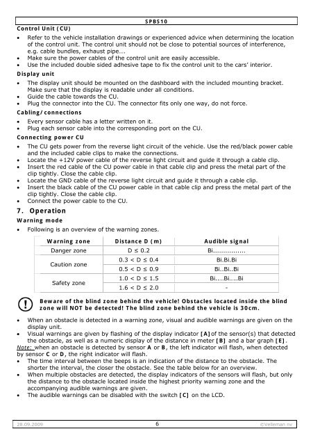
SPBS10Control Unit (CU)• Refer to the vehiclee installation drawings or experienced advice when determining the locationof the control unit. The control unit should not be close to potential sources of interference,e.g. cable bundles,exhaust pipe… ….• Makesure the power cables of the control unit are easily accessible.• Use the included double sided adhesive tape to fix the control unit to the cars’ interior.Display unit• The display unit should be mounted on the dashboard with the included mounting bracket.Makesure that thedisplay is readable under all conditions.• Guide the cable towards the CU.• Plug the connector into the CU. The connector fits only one way, do not force.Cabling/connections• Every sensor cablehas a letter written on it.• Plug each sensor cable into the corresponding port on the CU.Connecting power CU• The CU gets powerfrom the reverse light circuit of the vehicle. Use the red/ /black power cableand the included cable clips to make the connections.• Locate the +12V power cable of the reverse light circuit and guide it through a cable clip.• Insert the red cableof the CU power cable in that cable clip and press the metal part of theclip tightly. Close the cable clip.• Locate the GND cable of the reverse light circuit and guide it through a cable clip.• Insert the black cable of the CU power cable in that cable clipand press themetal part of theclip tightly. Close the cable clip.• Connect the powercable to the CU.7. OperationWarningmode• Following is an overview of the warning zones.Warning zoneDanger zoneCaution zoneSafety zoneDistance D (m)D ≤ 0.20.3 < D ≤ 0.40.5 < D ≤ 0.91.0 < D ≤ 1.51.6 < D ≤ 2.0Audible signalBi.............. ...Bi.Bi.BiBi..Bi..BiBi..…Bi…..B-Beware of the blind zone behind the vehicle! Obstacles located inside the blindzone will NOTbe detected! The blind zone behind the vehicle is 30cm.• When an obstacle is detected in a warning zone, visual and audible warnings are given onthedisplay unit.• Visual warnings aregiven by flashing of the display indicator [A]of the sensor(s) that detectedthe obstacle, as well as a numeric display of thedistance in meter [B] and a bar graph [E].Note: when an obstacle is detected by sensor A or B, the left indicator will flash, when detectedby sensor C or D, the right indicator will flash.• The time interval between the beeps is an indication of the distance to the obstacle. Theshorter the interval, the closer the obstacle. See the table below for an overview.• When multiple obstacles are detected, the display indicators of the sensors will flash, but onlythe distance to theobstacle located inside the highest prioritywarning zoneand theaccompanying audible warnings are given.• The audible warnings can be disabled with the switch [C] on the LCD.28.09.20096©<strong>Velleman</strong> nv