Create successful ePaper yourself
Turn your PDF publications into a flip-book with our unique Google optimized e-Paper software.
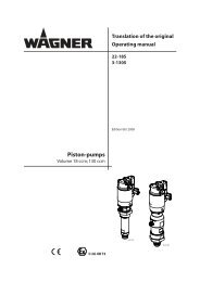
<strong>Finish</strong> <strong>270</strong> / <strong>250</strong>GBrepairs at the unit10 REpAIRS AT ThE uNITSwitch the unit off.Before all repair work: Unplug the powerplug from the outlet.10.1 INlET vAlvE puShER1. Use a 17 mm spanner to screw out the inlet valve button.2. Replace the wiper (1) and O-ring (2).Installation1. Insert the inlet valve (2) into the trigger housing (1) andsecure with the clasp (3). Ensure that the (black) seal (5) ismounted in the trigger housing.2. Screw the unit from the trigger housing and the inlet valveinto the paint section. The same (black) seal (6) has tobe mounted in the paint section.3. Tighten the trigger housing with the 30 mm wrench andtighten with three light blows of the hammer on the endof the wrench. (Corresponds to approx. 90 Nm tighteningtorque).2131524610.2 INlET vAlvE1. Place the enclosed 30 mm wrench on the trigger housing(1).2. Loosen the trigger housing (1) with light blows of a hammeron the end of the wrench.3. Screw out the trigger housing with the inlet valve (2) fromthe paint section.4. Pull of the clasp (3) using the enclosed screwdriver.5. Place the enclosed 30 mm wrench on the inlet valve (2).Turn out the inlet valve carefully.6. Clean the valve seat (4) with a cleaning agent and brush(ensure that no brush hairs are left behind).7. Clean the seals (5, 6) and check for damage. Replace, if necessary.8. Check all the valve parts for damage. In case of visiblewear replace the inlet valve.10.3 OuTlET vAlvE1. Use a 22 mm wrench to screw the outlet valve from thepaint section.2. Carefully pull of the clasp (1) using the enclosed screwdriver.The compression spring (2) presses ball (4) and valveseat (5) out.3. Clean or replace the components.4. Check the O-ring (7) for damage.5. Check the installation position when mounting the springsupport ring (3) (clipped onto spring (2)), outlet valve seat(5) and seal (6), refer to figure.45