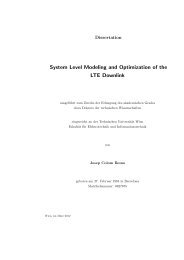
¡¤¥¦§¨¡¢£¤¨ ¡¢¤¥¦§¨ ¡¤¨ ¡¢¤¨¡¢£¤¥¦§¨ ¡¢¤¥¦§¨ ¡¤¨ ¡¤¨ ¡¢£¤¨ ¡¢£¤¨ ¢£¤¥¨ ¡¢£¤¥¦§¨¡¢¤¥¦§¨ ¢¤¥¨ ¢¤¥¨ ¡¢¤¥¦§¨VI INTERNATIONAL TELECOMMUNICATIONS SYMPOSIUM (ITS2006), SEPTEMBER 3-6, 2006, FORTALEZA-CE, BRAZILOSTBC ¡¢¤¨Fig. 1: Transmission <strong>of</strong> the i-th user signal s i (b, n) towards user u, using Orthogonal Space-Time Block Code (OSTBC) beforethe precoder ω i . ¡¢©¤¨ ¢©¤¥¨¡¢©¤¨<strong>of</strong> the i-th user’s signal, received by user u. This precoder isan extension <strong>of</strong> the purely spatial downlink beamforming andcan be seen as a transformation that, for each user, transformsthe K real antennas into L virtual antennas, where L ≤ K.Transmit diversity is thus applied to these virtual antennas.¡¢©¤¨Each precoder layer w i (l) beamforms the signal s i,l (b, n) andalso scales its power. The OSTBC block in Fig. 1 correspondsto the coding <strong>of</strong> the transmitted signal by an Orthogonal Space-Time Block Code (OSTBC). We further assume that the signalis transmitted in blocks <strong>of</strong> length N b , so that the channelvariation during one block <strong>of</strong> data is negligible. However, thechannel changes from one block b to another, characterizing ablock-fading channel. Moreover, we assume that the channelis flat.Considering the transmission <strong>of</strong> the i-th user’s signal, thesignal at the k-th antenna output and block b is given byx i,k (b, n) =L∑wi,k(l)s ∗ i,l (b, n) , (1)l=1where s i,l (b, n) are the “coded” symbols <strong>of</strong> the i-th user (afterthe TD processing) and w i,k (l) are the coefficients <strong>of</strong> the i-thuser’s precoder related to real antenna k and virtual antenna l.We assume that within a block, the time index n varies from0 to N b − 1.The total multi-user signal at antenna k is then given byx k (b, n) =U∑x i,k (b, n) . (2)i=1So, at a given block b, the received signal y u (b, n) at the u-thuser’s antenna can be expressed by¡¢©¤¥¦§¨y u (b, n) =U∑i=1 k=1K∑h u,k (b)x k (b, n) + ν(b, n) , (3)where h u,k (b) is the coefficient <strong>of</strong> the channel that linksantenna k and user u, and ν(b, n) is the additive gaussiannoise sample at the user’s antenna.By inserting (2) into (3) we can write(U∑L−1∑ K)∑y u (b, n) = wi,k(l)h ∗ u,k (b) s i,l (b, n)+ν(b, n) ,i=1 l=0k=1or rather, in vector formy u (b, n) =(4)U∑L−1∑w i (l) H h u (b)s i,l (b, n) + ν(b, n) , (5)i=1 l=0where the l-th precoder layer w i (l) =[w i,1 (l) w i,2 (l)T· · · w i,K (l)]is a vector that maps the i-th user’s l-thvirtual antenna[into the K real antennas (see Fig. 1) andTh u (b) = h u,1 (b) h u,2 (b) · · · h u,K (b)]is the spatialchannel vector that links the BS and user u.In order to obtain a full matrix notation, we now definethe signal s i,l (b, n) filtered by the spatial channel h u (b) as˜s i,u,l (b, n) h u (b)s i,l (b, n). By stacking the vectors w i (l)and the vectors ˜s i,u,l (b, n) for l = 1, . . .,L in the vectors ω i ¡¢¤¨ ¡¢¤¨ ¡¢¤¨ ¡¢¤¨
VI INTERNATIONAL TELECOMMUNICATIONS SYMPOSIUM (ITS2006), SEPTEMBER 3-6, 2006, FORTALEZA-CE, BRAZILand ˜S i,u (b, n), respectively, we can rewrite (5) asy u (b, n) =U∑ω H ˜S i i,u (b, n) + ν(b, n) , (6)i=1] Twhere ω i =[w i (1) T w i (2) T · · · w i (L) Trepresents the i-th user’s [ precoder in vector formand ˜Si,u (b, n) = ˜s i,u,1 (b, n) T ˜s i,u,2 (b, n) T · · ·˜s i,u,L (b, n) T ] T. The precoders ωi are assumed to benormalized, i.e., ‖ω i ‖ = 1.The vector ˜S i,u (b, n) is related to the signals s i,l (b, n) bythe channel convolution matrix H u (b) as˜S i,u (b, n) = H u (b)s i (b, n) , (7)[] Twhere s i (b, n) = s i,1 (b, n) s i,2 (b, n) · · · s i,L (b, n)is the coded signal vector and the KL×L channel convolutionmatrix is given by⎡⎤h u (b) 0 0 · · · 00 h u (b) 0 · · · 0H u (b) = ⎢⎣.. . . ..⎥. ⎦ , (8)0 0 0 · · · h u (b)where 0 is a column vector composed by K zeros.Finally, we can write y u (b, n) asy u (b, n) = ω H u H u(b)s u (b, n) +} {{ }y u,u(b,n)U∑ω H i H u(b)s i (b, n) +ν(b, n) . (9)i=1i̸=u} {{ }y u,i(b,n)It is worth recalling that for each block b the channel h u (b)presents a different condition, i.e., it can be in a deep fade orin a good condition. This condition affects the received powerand the SINR <strong>of</strong> each user.Based on (9) we can write the useful received power foruser u at block b as{∣∣yu,u(b, n) ∣ }2P u (b) = E= p u ω H u R u (b)ω u , (10)where R u (b) = H u (b)H u (b) H is the instantaneous DCCM <strong>of</strong>the u-th user at block b, which has a block hermitian structure.We have used the fact that the coded symbols are i.i.d. andtheir power is p u , which came from the fact that an OSTBCis used, which is an orthogonal code, and the assumption thatthe “uncoded” symbols s u (b, n) are i.i.d. and have power p u .Remark that p u is the transmit power for user u, while thetotal transmit power is given by P TX = ∑ p u .uFollowing the same reasoning as for the useful power, wecan write the interference caused by all other users in user uasU∑I u (b) = p i ω H i R u(b)ω i . (11)i=1i̸=uFinally, the SINR <strong>of</strong> the u-th user at the block b is givenbyp u ω H u R u (b)ω uγ u (b) =, (12)U∑p i ω H i R u(b)ω i + σν2i=1i̸=uwhere σν 2 is the noise variance.Assuming the use <strong>of</strong> a linear modulation, the BER for blockb can be approximated [11], at relatively high SINR, by)BER u (b) ≈ N eN Q (√d2min2 γ u(b), (13)where N is the number <strong>of</strong> bits per symbol, d min is theminimum distance between 2 points for a unitary power constellation,N e is the mean number <strong>of</strong> neighbors at minimum∞∫distance and Q(x) = √ 12πx(exp−t 22)dt is the Q-function.III. MULTI-USER MINIMUM TRANSMIT POWER WITHBER CONSTRAINTSAs far as diversity is concerned, the optimum precoders aresuch that the virtual antennas are uncorrelated, which wouldprovide the maximum channel diversity for the OSTBC. Onthe other hand, from the point <strong>of</strong> view <strong>of</strong> multi-user downlinkbeamforming, it is desirable that each precoder layer w i (l)beamforms the signal s i,l (b, n) towards the desired user i andmitigates the interference radiated towards all the other users,called pollution here. These two goals are clearly contradictory,since uncorrelated antennas means omnidirectionaltransmission and beamforming requires correlated antennas.As we have mentioned earlier, we propose a design criterionto optimize the precoders ω i in order to find the best trade<strong>of</strong>fbetween both wishes, i.e., maximum channel diversity andminimum pollution. These precoders lead to minimum BERfor a given transmit power. However, in a multi-user scenario,it makes more sense to minimize the total transmit power whilerespecting a target BER for each user within the consideredcell.From the BER expression in (13), we can write the proposedcriterion as∑min P TX = U p u ω H u ω uu=1{s.t.BER u EN eN Q ( √Nsγ u (b)) } = c u ∀u, (14)where c u is the target BER for user u and, for the sake <strong>of</strong>legibility, the have defined N s = d2 min2 .By introducing the Lagrange multipliers λ u , the lagrangianassociated with (14) can be written as{U∑U∑J = p u ω H u ω N e(√ )u+ λ u(E} )N Q Ns γ u (b) −c u .u=1u=1(15)Let( us define f(γ u (b)) as minus the derivative <strong>of</strong>√Ns )N eN Q γ u (b) with respect to γ u (b), given by(N e N sf(γ u (b)) 2N √ 2πN s γ u (b) exp − N )sγ u (b). (16)2