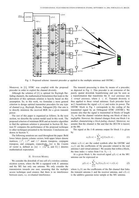
¢£¤¥¦¡¢¦¢¦ ¢£¤¥¦ ©¢¦©¢£¤¥¦¡¢£¤¥¦¡¢¦ ¢¦¡¢¦ ¢¦ ©¢¦¢¦ ©¢¦¨¡¢£¦ ¡¢£¤¥¦©¢£¤¥¦ ¨©¢£¦ ¨¢£¦ ¢£¤¥¦VI INTERNATIONAL TELECOMMUNICATIONS SYMPOSIUM (ITS2006), SEPTEMBER 3-6, 2006, FORTALEZA-CE, BRAZILOSTBC¢¦ ¢¦ Fig. 1: Proposed scheme: transmit precoder ω applied to the multiple antennas and OSTBC.§¢¦ §¢¦ Moreover, in [1], STBC was coupled with the proposedprecoder in order to exploit the channel diversity.Although the solution <strong>of</strong> [1] is optimal for Rayleigh flatfadingchannels, the mathematical formulation that leads to thederivation <strong>of</strong> this optimum solution is heavily based on thisassumption. So, in this work, we formulate a more general§¢¦criterion to design optimal transmitter precoders for any type<strong>of</strong> channel (e.g., Rayleigh, Rician, Nakagami [9]). Our aim isto directly minimize the received BER for a given transmitpower.The rest <strong>of</strong> this paper is organized as follows. In the nextsection, we describe the system model used in this work. Theproposed criterion <strong>of</strong> minimum BER and an iterative algorithmto find the optimum solution is presented in Section III. SectionIV compares the performance <strong>of</strong> the proposed techniqueto other techniques presented in the literature. Conclusions aredrawn in Section V.The following notations are used throughout the paper. Boldlower letters denote column vectors, bold upper letters denotematrices; (·) T , (·) H and (·) ∗ denote transpose, conjugatetranspose, and conjugate, respectively. ‖x‖ is the 2-norm<strong>of</strong> vector x, defined as ‖x‖ = √ x H x, and E{·} denotesmathematical expectation.II. SYSTEM MODELWe consider the downlink <strong>of</strong> one cell <strong>of</strong> a wireless communicationsystem, where the BS is equipped with K antennasand the MU has only one antenna. We only consider thetransmission towards one user, assuming that the multipleaccess technique used ensures that there is no interferencebetween users, i.e, co-channel interference.¨§¢£¦ The transmit processing is done by means <strong>of</strong> a precoder,as depicted in Fig. 1. This precoder is an extension <strong>of</strong> thepurely spatial downlink beamforming and can be seen asa transformation that transforms the K real antennas intoL virtual antennas, where L ≤ K. Transmit diversity isthus applied to these virtual antennas. Each precoder layerw(l) beamforms the signal s§¢£¤¥¦l (b, n) and scales its power. TheOSTBC block in Fig. 1 corresponds to the coding <strong>of</strong> thetransmitted signal by an Orthogonal STBC (OSTBC). Weassume also that the signal is transmitted in blocks <strong>of</strong> lengthN b , so that the channel variation during one block <strong>of</strong> data isnegligible. However, the channel changes from one block b toanother, characterizing a block-fading channel. Moreover, weassume that the channel is flat and that the DCCM is knownat the BS.The signal at the k-th antenna output for block b is givenbyx k (b, n) =L∑wk ∗ (l)s l(b, n) , (1)l=1where s l (b, n) are the coded symbols after the OSTBC andw k (l) are the coefficients <strong>of</strong> the precoder related to the realantenna k and virtual antenna l. We assume that within a block,the time index n varies from 0 to N b − 1.At a given block b, the received signal y(b, n) at the MUantenna can be expressed asK∑y(b, n) = h k (b)x k (b, n) + ν(b, n) (2)k=1where h k (b) are the coefficients <strong>of</strong> the flat channel that linksthe transmit antenna k and the receiver antenna, and ν(b, n)is the additive gaussian noise sample at the MU antenna.
VI INTERNATIONAL TELECOMMUNICATIONS SYMPOSIUM (ITS2006), SEPTEMBER 3-6, 2006, FORTALEZA-CE, BRAZILBy inserting (1) into (2), we can write that(L∑ K)∑y(b, n) = wk ∗ (l)h k(b) s l (b, n) + ν(b, n) . (3)l=1k=1By defining the l-th precoder layer w(l) =[w 1 (l) w 2 (l)T· · · w K (l)], which maps the l-th virtual antenna into theK real antennas[(see Fig. 1), and the spatial channel vectorTh(b) = h 1 (b) h 2 (b) · · · h K (b)], which links themultiple antennas at the BS and the MU’s antenna, we canrewrite the summation over k in (3) as a dot product to getL∑y(b, n) = w(l) H h(b)s l (b, n) + ν(b, n) . (4)l=1We now define the signal s l (b, n) filtered by the spatialchannel h(b) as ˜s l (b, n) h(b)s l (b, n). By stacking theprecoder layers w(l) and the vectors ˜s l (b, n) for l = 1, . . .,Lin the vectors ω and ˜S(b, n), respectively, we can rewrite (4)asy(b, n) = ω H ˜S(b, n) + ν(b, n) , (5)[] Twhere ω = w(1) T w(2) T · · · w(L) T representsthe precoder in vector form and ˜S(b,[n) = ˜s 1 (b, n) T˜s 2 (b, n) T · · · ˜s L (b, n) T ] T. The precoder is assumed to benormalized, i.e., ‖ω‖ = 1.The vector ˜S(b, n) can be related to the coded symbolss l (b, n) by the channel convolution matrix H(b) as˜S(b, n) = H(b)s(b, n) , (6)[Twhere s(b, n) = s 1 (b, n) s 2 (b, n) · · · s L (b, n)]is thecoded signal vector and the KL × L channel convolutionmatrix is given by⎡⎤h(b) 0 0 · · · 00 h(b) 0 · · · 0H(b) = ⎢⎣.. . . ..⎥. ⎦ , (7)0 0 0 · · · h(b)where 0 is a column vector composed by K zeros.We can thus rewrite the received signal at the MU y(b, n)asy(b, n) = ω H H(b)s(b, n) +ν(b, n) , (8)} {{ }y u(b,n)It is worth recalling that for each block b the channel presentsa different condition, i.e., it can be in a deep fade or in a goodcondition. This condition affects the received signal power andthe SNR at the MU.The useful received power by the MU during block b isgiven by} ∣∣∣yu P(b) = E{(b, n) ∣ 2 (9)= ω H H(b)E{s(b, n)s H (b, n)}H(b) H ω .Assuming that the “uncoded” symbols s(b, n) are i.i.d. withpower P TX and using the fact that an OSTBC is used, whichis an orthogonal code, we obtain that the “coded” symbolsare { also i.i.d. with}the same power P TX . Thus, we have thatE s(b, n)s H (b, n) = P TX I and (9) becomesP(b) = P TX ω H R(b)ω , (10)where R(b) = H(b)H(b) H is the instantaneous DCCM forblock b. Further assuming that the noise power is σν 2 we obtainthe SNR for block b asω H R(b)ωγ b = P TXσν2 . (11)Assuming the use <strong>of</strong> a linear modulation, the BER for blockb can be approximated [10], at relatively high SNR, by)BER(b) ≈ N eN Q (√d2min2 γ b, (12)where N is the number <strong>of</strong> bits per symbol, d min isthe minimum distance between 2 points for a unitarypower constellation, N e is the mean number <strong>of</strong> neighborsat minimum distance and the Q-function is given by∞∫ ( )Q(x) = √ 12πexp dt.x−t 22III. MINIMUM BER CRITERIONAs mentioned before, downlink beamforming and transmitdiversity are both beneficial to the link quality, in terms <strong>of</strong>reducing the BER for a given transmit power. However, theyhave opposite premises and can not be easily joined. In thisaim, we propose a design criterion to optimize the precoderω to directly minimize the BER <strong>of</strong> the received signal atthe MU, for a given transmit power at the BS. This can beseen as an extension <strong>of</strong> the purely spatial beamforming, whichaims to minimize the BER by maximizing the SNR <strong>of</strong> thereceived signal. We will show that this optimum precoder leadsto significantly better performances than the OSTBC applieddirectly to the real antennas.From the BER expression in (12), we can write the proposedcriterion as{(Nmin BER E eN Q √Ns ) }γ b, (13)s.t. ω H ω = 1where, for the sake <strong>of</strong> legibility, we have defined N s = d2 min2 .In order to find the optimum point <strong>of</strong> the criterion (13), wepropose to use an iterative algorithm based on the gradient (orsteepest descent) method [11]. The constraint will be treatedby applying the gradient method to the unconstrained functionand, after each iteration, projecting the unconstrained solutioninto the constrain set so that it satisfies the constraint. Thismethod is well suited for the type <strong>of</strong> constraint that we havehere, i.e., equally constrain <strong>of</strong> a simple form.Let us define f(γ b ) as the derivative <strong>of</strong> Q( √ N s γ b ) withrespect to γ b , given bydQ( √ N s γ b )dγ bN s= −2 √ exp2πN s γ b(− N sγ b2) −f(γ b ) .(14)