KR C1 A - KUKA Robotics
KR C1 A - KUKA Robotics
KR C1 A - KUKA Robotics
- No tags were found...

You also want an ePaper? Increase the reach of your titles
YUMPU automatically turns print PDFs into web optimized ePapers that Google loves.
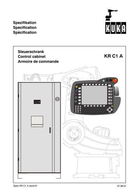
SpezifikationSpecificationSpécificationSteuerschrankControl cabinetArmoire de commande<strong>KR</strong> <strong>C1</strong> ASpez <strong>KR</strong> <strong>C1</strong> A de/en/fr07.99.01
2Spez <strong>KR</strong> <strong>C1</strong> A de/en/fr 07.99.01
Deutsch Seite 3English page 16Français page 23Inhaltsverzeichnis1 Systembeschreibung ...... 31.1 Allgemeines .................... 31.2 Steuerung ..................... 31.3 Steuerschrank .................. 51.4 Leistungsteil .................... 61.5 Rechnerteil ..................... 61.6 <strong>KUKA</strong> Control Panel (KCP) ....... 71.7 Arbeitsweise und Funktionen derSteuerung ..................... 71.7.1 Positionieren ................... 71.7.2 Bewegungsführung .............. 71.7.3 Programmierung ................ 72 Technische Daten ......... 8IllustrationenKühlkreisläufe .......... 10Leistungs--/Rechnerteil ... 11Hauptabmessungen ..... 13Anreihbarkeit ........... 14Schwenkbereich Tür/Schwenkrahmen ........ 151 Systembeschreibung1.1 AllgemeinesDie <strong>KUKA</strong>--Roboter <strong>KR</strong> 350, <strong>KR</strong> 60 P, <strong>KR</strong> 100 P,<strong>KR</strong> 100 PA und <strong>KR</strong> 160 PA sind mit der Steuerung<strong>KR</strong> <strong>C1</strong> A ausgerüstet. Steuerungs-- und Leistungselektroniksind in einem gemeinsamenSteuerschrank integriert. Der Sicherheitsstandardentspricht DIN EN 775. Die Versorgung derAntriebe erfolgt pro Achse durch einen Antriebsregler,welcher zentral durch das KPS mit Energieversorgt wird. Die Schnittstelle zwischen PC undAntriebsregler ist die DSE (Digitale--Servo--Elektronik)mit Interbusschnittstelle. Das Rechnerteilbasiert auf einer Standard PC Hardware mit leistungsfähigemPentium Mikroprozessor undBedienoberfläche unter Windows 95 .Pentium ist ein eingetragenes Warenzeichen der Intel CorporationWindows 95 ist ein eingetragenes Warenzeichen der Microsoft CorporationDie leistungsfähige Bahnsteuerung für 6 Grundachsenund 2 Zusatzachsen (Option: entwedereine Zusatzachse und Rückspeiseeinheit, oderzwei Zusatzachsen) umfaßt umfangreicheGrundfunktionen für die Roboterbewegung. ZahlreicheSonderfunktionen ermöglichen auf einfacheund wirtschaftliche Weise die Automatisierungder Roboterperipherie. Zusätzlich kannumfassend in die Kommunikation der Gesamtanlageeingegriffen und somit technologische Aufgabenkomplett gelöst werden.-- Abfragen und Steuern von Peripheriesignalen-- Schnelle und gezielte Reaktion auf Ereignisse-- Logische und arithmetische Verknüpfungen-- Kommunikation mit externen SteuerungsgerätenDie Steuerung ist für PTP-- (Punkt--zu--Punkt), Linear--und Zirkularbewegungen konzipiert unddeckt damit das Einsatzspektrum von einfachstenMontage-- bis hin zu komplexen Bahnbearbeitungsaufgabenab, wie zum Beispiel:-- Montieren-- Pressenverketten-- Handhabung-- Punktschweißen-- Bahnschweißen-- Maschinenbeschicken-- Palettieren-- Entgraten-- Wasserstrahlschneiden.1.2 SteuerungDie Steuerung enthält alle Bauteile und Funktionen,die zum Betrieb des Roboters erforderlichsind (siehe auch Abschnitt 2, Technische Daten).07.99.01 Spez <strong>KR</strong> <strong>C1</strong> A de/en/fr 3
Zulässige Leitungslängen(Längenbezeichnung L1, L2 siehe Abb. 1).Toleranz der Leitungen: +0,2 m bis --0,05 mLeitungsbezeichnungMotorleitung(Motor--/ Bremsenüberwachung)Längen--bezeichnungStandard--längen in mSonder--längen in mL1 7 bis 25Meßleitung(Steuerleitung) L1 7 bis 25KCP--Leitung L2 10 max.100Beim Einsatz eines Roboters auf einer zusätzlichenFahrachse sind in der Fahrachsen--Installationfolgende maximale Leitungslängen zulässig:Länge der Verbin--dungsleitung [m]Leitungslänge inder Fahrachsen--Installation [m]RobotermechanikPeri--pherieAbb. 1L1Motor--leitungMeß--leitungPeripherie--leitungen*)7 1515Steuerung7KCP--LeitungL225--KCP*) Länge je nach Anlage und KundenwunschVerbindungsleitungenSicherheitseinrichtungenDie <strong>KR</strong> <strong>C1</strong> A bietet mit einer Reihe von Maßnahmenein durchgängiges Sicherheitskonzept fürden Roboter und die Gesamtanlage, das dieNorm DIN EN 775 erfülltDas <strong>KR</strong> <strong>C1</strong> A--Sicherheitskonzept gewährleistetSicherheit am Roboter durch:-- NOT--AUS--Taster am <strong>KUKA</strong> Control Panel(zweikanalig)-- Schlüsselschalter zur Betriebsartenanwahl-- Drei ergonomisch angeordnete Zustimmungsschalteram <strong>KUKA</strong> Control Panel (zweistufig,zweikanalig).-- Schutzeinrichtungen (Bedienerschutz zweikanalig)-- Bewegungsraumbegrenzung-- Überwachung und Auswertung der Sicherheitselementein “sicherer Technik”.-- Einbindung der Sicherheitssignale von der Gesamtanlagein “sicherer Technik”.Die Farben und Anordnung bewegungsauslösenderTasten entsprechen den einschlägigen Vorschriften.Für den Betrieb des Roboters unterscheidet dieDIN EN 775 drei Betriebsarten mit unterschiedlichenSicherheitsstufen:D Betriebsart T1“Programmieren und Testen mit reduzierterGeschwindigkeit”-- Das Verfahren des Roboters darf nur mit Tippschaltungder Tasten bzw. der 6D--Mouse erfolgen.Zusätzlich muß ein Zustimmungsschalteram <strong>KUKA</strong> Control Panel betätigtwerden.-- Die maximale Verfahrgeschwindigkeit wird aufden im T1--Betrieb zulässigen Wert begrenzt.D Betriebsart T2“Testen mit Arbeitsgeschwindigkeit”-- Das Verfahren des Roboters darf nur mit Tippschaltungder Tasten bzw. der 6D--Mouse erfolgen.Zusätzlich muß ein Zustimmungsschalteram <strong>KUKA</strong> Control Panel betätigtwerden.-- Das Verfahren mit Arbeitsgeschwindigkeit istmöglich.D AutomatikbetriebsartenAUTO-- Es dürfen sich keine Personen im Arbeitsbereichdes Roboters aufhalten.-- Die Roboterbedienung erfolgt über das KCP,das sich außerhalb des Arbeitsbereiches desRoboters befinden muß.EXTERN-- Es dürfen sich keine Personen im Arbeitsbereichdes Roboters aufhalten.-- Die Roboterbedienung erfolgt über einen Leit--rechner (Option) oder SPS (Option).4Spez <strong>KR</strong> <strong>C1</strong> A de/en/fr 07.99.01
Zusätzliche Sicherheitsfunktionen:D Leistungsteilüberwachungen-- Unterspannung-- Überspannung-- Motorüberstrom-- Motortemperatur-- Verstärkerfehler-- Resolverfehler-- Bremsenfehler-- ÜbertemperaturD Rechnerteil--Überwachungen-- Temperatur-- Spannung-- Tiefentladeschutz Pufferakku-- KCPD Verfahr--ÜberwachungenKühlungDer Steuerschrank ist in zwei Kühlkreisläufe aufgeteilt.Der Innenbereich, mit der gesamten Steuerelektronik,wird über Wärmetauscher oder optionalüber ein Klimagerät gekühlt. ImAußenbereich werden Leistungsteil, Wärmetauscher,Ballastwiderstand und falls vorhandenTrafo direkt mit der Außenluft gekühlt (siehe Illustration1).In Betrieben mit hoher Luftverschmutzung mußder Außenbereich gelegentlich gereinigt werden.Schutzart: IP 54Schutz gegen Staubablagerung und Spritzwassernach EN 60529.FarbeSchrank: RAL 7032 (kieselgrau)Innen: verzinktTransportDer Steuerschrank kann mit Seil oder Transportgeschirran vier Ringschrauben (Abb. 2) transportiertwerden. Auch der Transport mit dem Gabelstapleroder Hubwagen ist möglich. Hierfür sindam Schrankboden Taschen angeschraubt.-- Software--Endschalter-- Solldrehzahlbegrenzung-- Sollgeschwindigkeit-- Sollbeschleunigung-- Positionierfenster-- Positionierzeit-- StillstandsfensterFALSCHRICHTIG-- Dynamischer Schleppfehler1.3 SteuerschrankBeim Transport des Steuerschrankes, durch Hubwagen,ist auf Kippgefahr zu achten!Der Steuerschrank enthält das Rechnerteil unddas Leistungsteil. Zum Rechnerteil gehören PC--Hardware und KCP. Zum Leistungsteil gehörenEinspeisung, Verstärker und zur Verknüpfungnotwendige Schütze und Relais.AbmessungenHöhe 1800 mm, Breite 800 mm, Tiefe 600 mmAusführungStahlblechschrank vollverzinkt mit Vordertür. EineSeitenwand und die Rückwand können geöffnetwerden, um gegebenfalls Wärmetauscher undBremswiderstand reinigen zu können.Die Verbindungsleitungen werden an der Frontseitehinter der Schranktür angesteckt.Abb. 2Transport des SteuerschrankesAnschlußfeldAm Anschlußfeld hiner der Schranktür werden folgendeLeitungen angeschlossen:-- Schutzleiter (Potentialausgleich) zur Peripherie07.99.01 Spez <strong>KR</strong> <strong>C1</strong> A de/en/fr 5
1.6 <strong>KUKA</strong> Control Panel (KCP)Das ergonomisch gestaltete Control Panel dientzum Teachen und Bedienen der Robotersteuerung<strong>KR</strong> <strong>C1</strong> A und bildet somit die Mensch--MaschineSchnittstelle. Der Microcontroller sendetTastatur-- und Zustandsdaten über einen StandardCAN Bus an den PC und wird auf diesemWeg von der Steuerung initialisiert und parametriert.Die Displayinformation wird über eine separateHigh--Speed Schnittstelle seriell übertragen.Das KCP verfügt über ein 8 Zoll Vollgrafik--Farb--Display (VGA--Auflösung 640 x 480), eine Folientastatur,eine 6D--Mouse und die BedienelementeNOT--AUS, Antriebe Ein/Aus, Betriebsartenwahlschalterund Zustimmungsschalter.Das Display ermöglicht folgende Anzeigen:-- Anwenderprogramme, Programmstatus-- Unterbrechung, Override-- Programmbild, Bewegungsbild-- Istwertanzeige, Schleppfehleranzeige-- Online--Korrektur, Justagebild-- Roboterstellung, Verfahrart-- Schnittstellensignale, Meldungen-- Buchführung-- Help--Anzeige1.7 Arbeitsweise und Funktionen derSteuerung1.7.1 PositionierenÜber einen DIN--Stecker kann am KCP zusätzlicheine MF II Tastatur angeschlossen werden.Der Ethernet--Anschluß ermöglicht die Archivierungauf einem PC.Die Windowsoberfläche führt den Anwenderdurch alle Arbeitsschritte und ermöglicht eineschnelle und effiziente Programmierung:-- Inbetriebnahme der Robotersteuerung-- Programmerstellung-- Programmtest und --korrektur-- Programmsteuerung (Start, Stop)-- Beobachten und Diagnose bei laufender ProduktionD WegmessungDas KTL--Meßsystem erfaßt die absoluten Weg--Istwerte einer jeden Achse.D TransformationDie Transformation rechnet Achskoordinaten(Winkelwerte)inkartesischeKoordinaten(Strekken,Orientierungswinkel) um und umgekehrt.D RegelungLageregelung, Drehzahlregelung und feldorientierteStromregelung erfolgt in den Achsreglern.1.7.2 BewegungsführungD Koordinatensysteme-- Gelenkkoordinaten: achsspezifisch-- Kartesische Koordinaten: WORLD ROB--ROOT (Koordinatenursprung: Roboterfuß)TCP (Koordinatenursprung: Werkzeugspitze)BASE (Koordinatenursprung: Werkstück)D Bedienungsmöglichkeiten-- Anwahl über Verfahrart--Menü-- Verfahren mit 6D Mouse am KCP1.7.3 ProgrammierungDie Programmierung erfolgt in der <strong>KR</strong>L Sprache.Siehe hierzu Programmieranleitung <strong>KR</strong> <strong>C1</strong>.07.99.01 Spez <strong>KR</strong> <strong>C1</strong> A de/en/fr 7
2 Technische DatenNormen und Vorschriften:Der Steuerschrank <strong>KR</strong> <strong>C1</strong> A entspricht der:EG MaschinenrichtlinieEG NiederspannungsrichtlinieEG EMV--Richtliniein der zum Zeitpunkt der Auslieferung jeweils aktuellenVersion.Es wurden unter anderem folgendeNormen berücksichtigt: DINEN292DIN EN 775,DIN EN 418,DIN EN 60204/T1,DIN EN 614/T1,DIN EN 954,DIN EN 50081--2,DIN EN 50082--2Die Schutzart des Steuer--schranks entspricht IEC 529,IEC 144 und EN 60529: IP 54Zulässige klimatische undmechanische Beanspruchungen:Umgebungstemperatur beiBetrieb:ohne Klimagerät:mit Klimagerät:(noch in Entwicklung!)Umgebungstemperatur beiLagerung und TransportSteuerschrank:KCP:0 ˚C bis45 ˚C /55˚C(273 K bis 318 K / 328 K)+45 ˚C+55 ˚C--25 ˚C bis70˚C(248 K bis 343 K)--25 ˚C bis60˚C(248 K bis 333 K)Maximal zulässigeTemperaturänderung: 1,1 K/minLuftfeuchte nach: DIN EN 60204/4.4.3(DIN 40040 Feuchteklasse F)Geodätische Höhe nach: DIN EN 60204/4.4.4(DIN 40040 Höhenklasse N)Rüttelfestigkeit: DIN EN 60204/4.4.7(kurzzeitige ErschütterungenSchärfegrad 12 stationär und 22 beiTransport nach DIN IEC 68 T 2.6)Sind höhere mechanische Bean--spruchungen zu erwarten, mußder Schrank auf Schwingmetallgesetzt werden.Typ:<strong>KR</strong> <strong>C1</strong> AMax. Anzahl der Achsen: 6Erweiterung um 2 Zusatzachsenim selben SchrankGewicht ca :323 kg(ohne Transformator)Anreihbarkeit:seitlich, sieheIllustration 4Hauptabmessungen Illustration 3Aufstellbedingungen Illustration 4,5Netzanschlußwerte:ACHTUNG!Anschluß nur an Netzenmit geerdetemSternpunkt zulässig.Nennanschlußspannung Standardnach DIN/IEC 38:3 x 400 V ACZulässige Toleranz: 400 V --10%bis 415 V +10%andere Anschlußspannungenüber Vorschalttrafo (Option)Netzfrequenz:49 -- 61 HzNennanschlußleistung: 6kVAOberschwingungsgehalt(gemäß IEC 550 undDIN VDE 0160): 10%Spannungsunterbrechungbei Nennspannung und --strom: < 10 msDurchschnittlicherLeistungsverbrauch:3--5 kWAbsicherung netzseitig: 3x25Aträge,max. 32 APotentialausgleich:Für die Potentialausgleichsleitungen und alleSchutzleiter ist der gemeinsame Sternpunkt dieBezugsschiene des Leistungsteils.Bremse und Peripherie:Ausgangsspannung:24 VAusgangsstrom max: 10 AÜberwachung derBremsenleitung:VersorgungsspannungSteuerteil:Leitungsbruch,Kurzschluß24 VAnwender Ein--/Ausgängealle Ein--/Ausgänge galvanisch getrennt8Spez <strong>KR</strong> <strong>C1</strong> A de/en/fr 07.99.01
16 AnwendereingängeBinäreingänge mit VerpolungsschutzEingangsspannung:16 V bis 30 VEingangsstrom bei 24 V: ca. 6 mAGleichzeitigkeitsfaktor. 100%Filterkonstante:1--2msWurzelung: Gruppen zu 816 Anwenderausgänge 100 mA (Binär)Steuerspannung:18 V bis 30 VSpannungsabfall imEIN Zustand (100 mA):
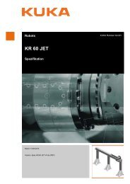
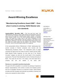
643455Seitenansicht äußerer KühlkreislaufSide view, outer cooling circuitVue latérale circuit de refroidissement extérieurRückansicht äußerer KühlkreislaufRear view, outer cooling circuitVue arrière circuit de refroidissement extérieur43121 Innerer KühlkreislaufInner cooling circuitCircuit de refroidissement intérieur2 Ventilator Innerer KühlkreislaufFan for inner cooling circuitVentilateur circuit de refroidissement intérieur3 Wärmetauscher seitlichLateral heat exchangerEchangeur de chaleur latéral4 Äußerer KühlkreislaufOuter cooling circuitCircuit de refroidissement extérieur5 Ventilator Äußerer KühlkreislaufFan for outer cooling circuitVentilateur circuit de refroidissement extérieur6 Wärmetauscher RückwandRear heat exchangerEchangeur de chaleur arrièreSteckerfeldConnector panelPanneau de raccordementVorderansicht innerer KühlkreislaufFront view, inner cooling circuitVue avant circuit de refroidissement intérieur1 KühlkreisläufeCooling circuitsCircuits de refroidissement10Spez <strong>KR</strong> <strong>C1</strong> A de/en/fr 07.99.01
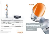
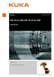
1234567891011121 Hauptschalter2 Servo Umrichter ESV9328, Achse 13 Servo Umrichter ESV9328, Achse 24 Servo Umrichter ESV9328, Achse 35 Rückspeiseeinheit oder Achse 8 (Option)6 Versorgungseinheit KPS--6007 Servo Umrichter ESV9326, Achse 48 Servo Umrichter ESV9326, Achse 59 Servo Umrichter ESV9326, Achse 610 Servo Umrichter ESV9326, Achse 7 (Option)11 Trafo (Option)12 Netzfilter1 2 3 4 5 6 7 8 9111213141516171018191 Motorleitung Achsen 1/3/4 (X20)2 Motorleitung Achsen 2/5/6 (X7)3 (Option)4 (Option)5 (Option)6 (Option)7 Datenleitung (X21)8 KCP--Anschluß (X19)9 Netzanschluß HAN 6 (X1)10 Servicesteckdose (X01) (Option)11 Niederspannungsnetzteil KPS 2712 Akkumulatoren 12 V / 4 Ah Pb13 3 1/2” Diskettenlaufwek14 PC--Schnittstellen15 Rechnerteil Schwenkrahmenrückseite16 CD--ROM Laufwerk17 Sicherheitslogik18 Motor-- und ResolversteckerZusatzachse 7 (Option)19 Motor-- und ResolversteckerZusatzachse 8 (Option)2 Leistungsteil/RechnerPower and computer unitsUnités de puissance et calculateur07.99.01 Spez <strong>KR</strong> <strong>C1</strong> A de/en/fr 11
Legend for Illustration 2 Légende de l’illustration 21 Main switch2 Servo converter ESV9328, axis 13 Servo converter ESV9328, axis 24 Servo converter ESV9328, axis 35 Energy recovery unit or axis 8 (optional)6 Supply unit KPS--6007 Servo converter ESV9326, axis 48 Servo converter ESV9326, axis 59 Servo converter ESV9326, axis 610 Servo converter ESV9326, axis 7 (optional)11 Transformer (optional)12 Mains filter1 Interrupteur principal2 Servo--variateur ESV9328, axe 13 Servo--variateur ESV9328, axe 24 Servo--variateur ESV9328, axe 35 Alimentation de retour ou axe 8 (Option)6 Unité d’alimentation KPS--6007 Servo--variateur ESV9326, axe 48 Servo--variateur ESV9326, axe 59 Servo--variateur ESV9326, axe 610 Servo--variateur ESV9326, axe 7 (Option)11 Transformateur (Option)12 Filtre secteur1 Motor cable, axes 1/3/4 (X20)2 Motor cable, axes 2/5/6 (X7)3 (Optional)4 (Optional)5 (Optional)6 (Optional)7 Data cable (X21)8 KCP connection (X19)9 Power supply connection HAN 6 (X1)10 Service socket (X01) (optional)11 Low--voltage power supply KPS 2712 Batteries 12 V / 4 Ah Pb13 3 1/2” floppy disk drive14 PC interfaces15 Computer unit (rear of swing frame)16 CD--ROM drive17 Safety logic18 Motor/resolver connector,external axis 7 (optional)19 Motor/resolver connector,external axis 8 (optional)1 Câbles moteur axes 1/3/4 (X20)2 Câbles moteur axes 2/5/6 (X7)3 (Option)4 (Option)5 (Option)6 (Option)7 Câble de données (X21)8 Connexion KCP (X19)9 Connexion secteur HAN 6 (X1)10 Prise SAV (X01) (Option)11 Bloc secteur BT KPS 2712 Accu 12 V / 4 Ah Pb13 3 1/2” unité de disquette14 Interfaces P<strong>C1</strong>5 Unité calculateur face arrière cadre pivotant16 Lecteur CD--ROM17 Logique de sécurité18 Connecteur moteur et résolveurAxe supplémentaire 7 (Option)19 Connecteur moteur et résolveurAxe supplémentaire 8 (Option)12Spez <strong>KR</strong> <strong>C1</strong> A de/en/fr 07.99.01
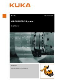
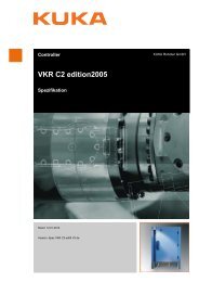
800 6001800VorderansichtFront viewVue face avantlinke SeiteLefthand sideCôté gaucheObenTopHaut3 HauptabmessungenPrincipal dimensionsDimensions principales07.99.01 Spez <strong>KR</strong> <strong>C1</strong> A de/en/fr 13
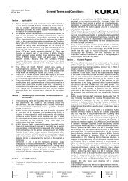
300Ansicht vorneFront viewVue face avant100Ansicht obenTop viewVue de dessus4 AnreihbarkeitInstallation with other cabinetsExtension14Spez <strong>KR</strong> <strong>C1</strong> A de/en/fr 07.99.01
RechnerteilComputer unitUnité calculateur5050seitlich angereihter SchrankButt--mounted cabinetArmoire juxtaposéeObenTopHautseitlich angereihter SchrankButt--mounted cabinetArmoire juxtaposéeca.approx.env.620 mmSchwenkbereich bei einzelstehendem Schrank:Tür ca. 180_, Rechnerrahmen ca. 180_bei aneinandergereihten SchränkenTür ca. 155_, Rechnerrahmen ca. 170_Swing range for stand--alone cabinet:door approx. 180_, computer frame approx. 180_for butt--mounted cabinets:door approx. 155_, computer frame approx. 170_Plage de pivotement pour armoire individuelle:porte env. 180_, cadre calculateur env. 180_pour armoires juxtaposées:porte env. 155_, cadre calculateur env. 170_ca.approx.env.520 mm5 Schwenkbereich Tür/SchwenkrahmenSwing range for door and computer framePlage de pivotement porte/cadre calculateur07.99.01 Spez <strong>KR</strong> <strong>C1</strong> A de/en/fr 15
Deutsch Seite 3English page 16Français page 23Contents1 System description ..... 161.1 General ....................... 161.2 Controller ..................... 161.3 Control cabinet ................ 181.4 Power unit .................... 191.5 Computer unit ................. 191.6 <strong>KUKA</strong> Control Panel (KCP) ...... 201.7 Control functions ............... 201.7.1 Positioning .................... 201.7.2 Motion control ................. 201.7.3 Programming .................. 202 Technical data .......... 21IllustrationsCooling circuits ......... 10Power and computer units 11Principal dimensions .... 13Installation with othercabinets ................ 14Swing range of door andcomputer frame ......... 151 System description1.1 GeneralThe <strong>KUKA</strong> robots <strong>KR</strong> 350, <strong>KR</strong> 60 P, <strong>KR</strong> 100 P,<strong>KR</strong> 100 PA and <strong>KR</strong> 160 PA are equipped with the<strong>KR</strong> <strong>C1</strong> A controller, whose control and powerelectronics are integrated in a common controlcabinet. This cabinet conforms to the safety requirementsspecified in DIN EN 775. Power issupplied to the drive motors by a drive controllerfor each axis, the drive controllers being suppliedwith power centrally by the KPS (<strong>KUKA</strong> PowerSupply). The interface between the PC and thedrive controllers is formed by the DSE (digitalservo--electronics) with its Interbus interface. Thecomputer unit is based on standard PC hardwarewith a powerful Pentium microprocessor and anoperator interface under Windows 95 .Pentium is a registered trademark of Intel Corporation.Windows 95 is a registered trademark of Microsoft Corporation.The powerful continuous--path control system for6 basic axes and 2 external axes (optional: eitherone external axis and an energy recovery unit, ortwo external axes) incorporates extensive basicfunctions for the robot motion. Numerous specialfunctions provide the capability of automating therobot periphery in a simple and cost--effectivemanner. It is additionally possible to intervene inthe communications of the overall system andthus to fully implement diverse technological functions.-- Scanning and processing of I/O signals-- Fast and selective reaction to process events-- Logic and arithmetic operations-- Communication with external control unitsThe control system is designed for point--to--point(PTP), linear and circular motions, thereby coveringa range of applications from the simplest assemblytasks right up to complex tasks requiringcontinuous--path control, such as:-- Assembly-- Press linking-- Handling-- Spot welding-- Arc welding-- Machine tending-- Palletizing-- Deburring-- Waterjet cutting.1.2 ControllerThe controller contains all the components andfunctions necessary for operation of the robot(see also Section 2, Technical Data).16Spez <strong>KR</strong> <strong>C1</strong> A de/en/fr 07.99.01
Permissible cable lengths(for length designations L1 and L2 see Fig. 1).Cable tolerance: +0.2 m to --0.05 mLengthdesignationStandardCable designationMotor cable(Motor/brake monitoring) L1 7Signal cable(control cable) L1 7KCP cableL2 10length in mOptionallengths in mup to25up to25max.100If a robot is mounted on an additional linear axis,the cables installed in the linear axis must not exceedthe following lengths:Length of connect--ingcable[m]Length of cablesinstalled in thelinear axis [m]ManipulatorPeri--pheryFig. 1L1MotorcableSignalcablePeripherycables *)7 1515Controller7KCPcableL225--KCP*) Length depends on system and customerrequirementsConnecting cablesSafety featuresThe <strong>KR</strong> <strong>C1</strong> A incorporates a number of measuresproducing a consistent safety concept for therobot and the overall system in compliance withthe requirements of DIN EN 775.The <strong>KR</strong> <strong>C1</strong> A safety concept guarantees safeoperation of the robot by means of:-- EMERGENCY STOP pushbutton on the<strong>KUKA</strong> Control Panel (two channels)-- Keyswitch for mode selection-- Three ergonomically arranged enablingswitches on the <strong>KUKA</strong> Control Panel (two positions,two channels)-- Safeguards (operator protection, two channels)-- Working space limitation-- Failsafe monitoring and evaluation of safetyelements-- Failsafe integration of safety signals from theoverall system.The colors and arrangement of motion--triggeringkeys comply with the relevant regulations.For operation of the robot, DIN EN 775 makes adistinction between the following operating modeswith different safety levels:DMode T1“Programming and testing at reduced velocity”-- The robot can be moved only in jog mode withthe traversing keys or the 6D mouse. In addition,an enabling switch on the <strong>KUKA</strong> ControlPanel must be pressed.-- The velocity is limited to the maximum valueallowed in the mode T1.DMode T2“Testing at working velocity”-- The robot can be moved only in jog mode withthe traversing keys or the 6D mouse. In addition,an enabling switch on the <strong>KUKA</strong> ControlPanel must be pressed.-- The robot can be moved at working velocity.DAutomatic modesAUTO-- No personnel are allowed in the working zoneof the robot.-- The robot is operated via the KCP, which mustbe located outside the working zone of therobot.EXTERNAL-- No personnel are allowed in the working zoneof the robot.-- Robot operation is controlled by a host computer(optional) or PLC (optional).07.99.01 Spez <strong>KR</strong> <strong>C1</strong> A de/en/fr 17
Additional safety functions:DPower unit monitoring functions-- Undervoltage-- Overvoltage-- Motor overcurrent-- Motor temperature-- Amplifier fault-- Resolver fault-- Brake fault-- Excess temperatureDComputer unit monitoring functions-- Temperature-- Voltage-- Exhaustive discharge protection, back--upbattery-- KCPDTraversing monitoring functions-- Software limit switches-- Command speed limitation-- Command velocity-- Command acceleration-- Positioning window-- Positioning time-- Standstill window-- Dynamic following error1.3 Control cabinetThe control cabinet contains the computer unitand the power unit. The computer unit comprisesthe PC hardware and the KCP, while the powerunit features the power feed components, amplifiersand all contactors and relays required for logicalconnection purposes.DimensionsHeight 1800 mm, width 800 mm, depth 600 mmDesignSheet steel cabinet, fully galvanized, with frontdoor. The rear panel and one side panel can beopened, enabling the heat exchangers and brakeresistor to be cleaned if necessary.The connecting cables are plugged into the frontof the cabinet behind the door.CoolingThe control cabinet is divided into two coolingcircuits. The inner zone, containing the entirecontrol electronics, is cooled by heat exchangersor an air conditioner (optional). In the outer zone,the power unit, heat exchangers, ballast resistorand, if installed, transformer are cooled directly byambient air (see Illustration 1).In plants with highly polluted air, the outer zonemust be cleaned occasionally.Degree of protection: IP 54Protection against dust deposits and water sprayaccording to EN 60529.ColorsCabinet: RAL 7032 (pebble gray)Inside: galvanizedSpecial colors available on request.TransportationThe control cabinet can be transported with ropeor transport tackle attached to four eyebolts(Fig. 2). Transport is also possible with a fork lifttruck or pallet truck, for which purpose fork slotsare bolted to the bottom of the cabinet.INCORRECTCORRECTIf the control cabinet is transported by pallet truck,it must be ensured that the control cabinet cannottopple over during transportation.Fig. 2Transporting the control cabinetConnection panelThe following cables can be connected to the connectionpanel behind the cabinet door:-- Ground conductor (equipotential bonding) tothe periphery18Spez <strong>KR</strong> <strong>C1</strong> A de/en/fr 07.99.01
-- Power supply cable 400 V-- Motor cable-- Signal cable / data cable-- Periphery cables and cables for options1.4 Power unitThe power unit comprises the areas highlighted inIllustration 2:-- Main switch-- Fuses-- Series transformer (optional)-- Low--voltage power supply KPS--27-- Supply unit KPS--600-- Axis controller-- Mains filterD The KPS--600 incorporates:-- Mains contactor-- Power supply-- Ballast circuit-- Brake switch (in common for all 6 robot axes)-- Monitoring of the heat sink temperature-- Interface with the DSE--IBS1.5 Computer unitWith its plug--in components, the computer unit(see Illustration 2) performs all the functions of thecontrol hardware. These are:-- Windows operator interface with visual displayand input-- Program creation, correction, archiving, maintenance-- Diagnosis, start--up assistance-- Sequence control-- Trajectory planning-- Control of the servo power unit-- Monitoring functions-- Safety logic-- Communication with external units (other controllers,host computers, PCs, network)The control hardware is composed of the followingmodules:-- Standard PC hardware with Pentium processor-- Multi--function card (MFC)-- Digital servo--electronics (DSE--IBS)-- Back--up battery for control hardwareD Standard PC hardwareWith its powerful Pentium processor and at least64 MB main memory, the standard PC hardwareforms the basis of the computer unit. The standardPC also includes a hard disk for storing the entirecontrol software, including online documentation,a floppy disk drive for archiving purposes and aCD--ROM drive for reading the CD--ROM suppliedin the cabinet.The CD--ROM contains the operating system,Windows 95, the control software including therelevant technological process, the online helpand the complete documentation for the controlcabinet and the robot.D Multi--function cardThe multi--function card incorporates the systemand user I/Os and an Ethernet controller, andforms the interface between the KCP and the PC.The card is designed as a PC plug--in card.D Digital servo--electronicsThe DSE--IBS module fitted on the multi--functioncard with its own DSP (digital signal processor) isresponsible for control of the KPS, the control ofthe axis controllers with axis speed commandvalues and parameterization data, and the processingof error and situation information and theposition values read by the axis controllers.D Back--up battery for control hardwareFor data protection, the computer is supplied withpower by a battery for approximately 10 minutesin the event of power failure.07.99.01 Spez <strong>KR</strong> <strong>C1</strong> A de/en/fr 19
1.6 <strong>KUKA</strong> Control Panel (KCP)The ergonomically designed hand programmingunit is used for teaching and operating the<strong>KR</strong> <strong>C1</strong> A robot controller and thus constitutes theman-- machine interface. The microcontrollersends keyboard and status data to the PC via astandard CAN bus, by which means it is initializedand parameterized by the controller. The displayinformation is transmitted serially via a separatehigh--speed interface.The KCP features an 8--inch full--graphics colordisplay (VGA resolution 640 x 480), a membranekeyboard, a 6D mouse and the operator controlelements EMERGENCY STOP, Drives ON/OFF,mode selector switch and enabling switch.The following displays are possible on the screen:-- Application programs, program status-- Interrupt, override-- Program display, motion display-- Actual value display, following error display-- Online correction, adjustment display-- Robot position, traversing mode-- Interface signals, messages-- Directory-- Help display1.7 Control functions1.7.1 PositioningIt is additionally possible for an MF II keyboard tobe connected to the KCP by means of a DIN connector.The Ethernet connection allows archiving on aPC.The Windows environment guides the userthrough all procedures and allows fast and efficientprogramming:-- Start--up of the robot controller-- Programming-- Program test and correction-- Program control (start, stop)-- Visualization and diagnostics during productionD Position sensingThe KTL position sensing system acquires the absoluteactual position data of each axis.D TransformationThe transformation converts axis coordinates(angle values) into cartesian coordinates (distances,orientation angles) and vice versa.D Servo--controlPosition control, speed control and field--orientedcurrent control are performed by the axis controllers.1.7.2 Motion controlD Coordinate systems-- Joint coordinates: axis--specific-- Cartesian coordinates: WORLD ROBROOT(coordinate origin: robot base)TCP (coordinate origin: tool center point)BASE (coordinate origin: workpiece)D Operator control options-- Selection via traversing mode menu-- Moving axes with 6D mouse on KCP1.7.3 ProgrammingProgramming is carried out in the <strong>KR</strong>L language.See <strong>KR</strong> <strong>C1</strong> Programming Guide for details.20Spez <strong>KR</strong> <strong>C1</strong> A de/en/fr 07.99.01
2 Technical dataStandards and specifications:The control cabinet <strong>KR</strong> <strong>C1</strong> A complies with the:EC Machinery DirectiveEC Low--voltage DirectiveEC EMC Directivein the version current at the time of delivery.The following standards have also been taken intoaccount, among others: DINEN292,DIN EN 775,DIN EN 418,DIN EN 60204--1,DIN EN 614--1,DIN EN 954,DIN EN 50081--2,DIN EN 50082--2The protection classificationof the control cabinet conformsto IEC 529, IEC 144 andEN 60529: IP 54Permissible environmentaland mechanical conditions:Ambient temperatureduring operation:without air conditioner:with air conditioner:(still under development!)Ambient temperature duringstorage and transportationControl cabinet:KCP:0 ˚C to45 ˚C /55˚C(273 K to 318 K / 328 K)+45 ˚C+55 ˚C--25 ˚C to70˚C(248 K to 343 K)--25 ˚C to60˚C(248 K to 333 K)Maximum permissible rateof temperature change: 1.1 K/minAir humidity acc. to: DIN EN 60204/4.4.3(DIN 40040 humidity class F)Altitude acc. to: DIN EN 60204/4.4.4(DIN 40040 altitude class N)Vibration resistance: DIN EN 60204/4.4.7(short--time vibrations up to degreeof severity 12 when stationary or 22during transportation according toDIN IEC 68 T 2.6)If more severe mechanical stressis expected, the cabinet must befitted with anti--vibration mounts.Type:<strong>KR</strong> <strong>C1</strong> AMaximum number of axes: 6Expansion possible with2 external axes in the samecabinetWeight:approx. 323 kg(without transformer)Installation with other side--by--side,cabinets: see Illustration 4Principal dimensions: Illustration 3Installation conditions: Illustrations 4, 5Mains connection ratings:Caution:Connection only permittedto grounded--neutral systems.Standard rated supply voltageaccording to DIN/IEC 38: 3 x 400 V ACPermissible tolerance: 400 V --10%to 415 V +10%Other supply voltagesvia series transformer (optional)Power frequency:49 -- 61 HzRated connected load: 6kVAHarmonic content(according to IEC 550 andDIN VDE 0160): 10%Voltage interruption atrated voltage and current: < 10 msAverage power consumption: 3--5 kWMains--side fusing:3x25Aslow--blowing,max. 32 AEquipotential bonding:The common neutral point for the equipotentialbonding conductors and all protective ground conductorsis the reference bus of the power unit.Brake and periphery:Output voltage:24 VMaximum output current: 10 ABrake cable monitoring: open circuit,short circuitControl unitsupply voltage:24 VUser inputs/outputsall inputs/outputs electrically isolated07.99.01 Spez <strong>KR</strong> <strong>C1</strong> A de/en/fr 21
16 user inputsBinary inputs with reverse voltage protectionInput voltage:16 V to 30 VInput current at 24 V: approx. 6 mACoincidence factor. 100%Filter constant:1--2msGrouping: groups of 816 user outputs, 100 mA (binary)Control voltage:18 V to 30 VVoltage drop in ONstate (100 mA):
Deutsch Seite 3English page 16Français page 23Table des matières1 Description du système . 231.1 Généralités ................... 231.2 Commande ................... 231.3 Armoire de commande ......... 251.4 Unité de puissance ............. 261.5 Unité calculateur ............... 261.6 <strong>KUKA</strong> Control Panel (KCP) ...... 271.7 Fonctions et fonctionnement de lacommande .................... 271.7.1 Positionnement ................ 271.7.2 Commande du déplacement ..... 271.7.3 Programmation ................ 272 Caractéristiquestechniques ............. 28IllustrationsCircuits derefroidissement ......... 10Unités de puissance etcalculateur .............. 11Dimensions principales . 13Extension .............. 14Plage de pivotement porte/cadre calculateur ....... 15La commande performante de contournage pour6 axes de base et 2 axes supplémentaires (option:soit un axe supplémentaire et une unité d’alimentationde retour ou deux axes supplémentaires)comprend non seulement d’importantes fonctionsde base pour le déplacement du robot mais égalementde nombreuses fonctions spéciales permettantd’automatiser la périphérie du robot d’unemanière simple et rentable. On pourra en outre intervenirde manière globale dans la communicationde l’ensemble de l’installation pour résoudreainsi intégralement les tâches technologiques.-- Appel et commande des signaux périphériques-- Réaction rapide et ciblée en réponse à desévénements-- Fonctions logiques et arithmétiques-- Communication avec des appareils de commandeexternes.La commande conçue pour des positionnementsPTP (point à point) et des mouvements linéaireset circulaires couvre ainsi un vaste domained’application, du montage le plus simple jusqu’auxtâches les plus complexes de contournagecomme par exemple:-- Montage1 Description du système1.1 GénéralitésLes robots <strong>KUKA</strong> <strong>KR</strong> 350, <strong>KR</strong> 60 P, <strong>KR</strong> 100 P,<strong>KR</strong> 100 PA et <strong>KR</strong> 160 PA peuvent être dotés de lacommande <strong>KR</strong> <strong>C1</strong> A. Les systèmes électroniquesde commande et de puissance sont montésdans une armoire de commande commune. Le niveaude sécurité répond à la norme DIN EN 775.L’alimentation des entraînements est assurée,pour chaque axe, par un régulateur d’entraînementcaractérisé par une alimentation en énergiecentrale via la KPS. La servo--électronique numériqueDSE avec interface Interbus est l’interfaceentre le PC et les régulateurs d’entraînement.L’unité calculateur repose sur le matériel d’un PCstandard avec un microprocesseur Pentiumperformant et une interface utilisateur sous Windows95 .Pentium est une marque déposée par Intel CorporationWindows 95 est une marque déposée par Microsoft Corporation-- Chaînage des presses-- Manutention-- Soudage par points-- Soudage à l’arc-- Alimentation de machine-- Palettisation-- Ebarbage-- Découpage au jet d’eau.1.2 CommandeLa commande comprend tous les composants ettoutes les fonctions indispensables au fonctionnementdu robot (voir aussi paragraphe 2, “Caractéristiquestechniques”).07.99.01 Spez <strong>KR</strong> <strong>C1</strong> A de/en/fr 23
Longueurs de câbles autorisées(Désignation des longueurs L1, L2 voir Fig. 1).Tolérance des câbles: +0,2 m à --0,05 mDésignation du câbleCâble moteurs(surveillance moteurs/freins)Désignationde la longueurLongueursL1 7Câble de mesurage(câble de signaux) L1 7Câble KCPL2 10standard (m)Longueursspéciales (m)max.25max.25max.100Si l’on utilise un robot sur un axe linéaire supplémentaire,les longueurs maxi suivantes descâbles sont autorisées pour l’installation des axeslinéaires.Longueur du câblede liaison [m]Longueur du câble del’installation de l’axelinéaire [m]Mécanique du robotPéri--phérieL1CâblemoteursCâble demesurageCâblespériphérie*)7 1515Commande7CâbleKCPL225--KCP*) Longueur en fonction de l’installation et desspécifications du clientFig. 1Câbles de liaisonDispositifs de sécuritéGrâce à une série de mesures, la <strong>KR</strong> <strong>C1</strong> A offreun concept de sécurité intégral pour le robot et l’installationglobale répondant aux critères imposéspar la norme DIN EN 775.Le concept de sécurité <strong>KR</strong> <strong>C1</strong> A garantit la sécuritéau robot grâce aux critères suivants réalisés:-- Bouton ARRET D’URGENCE au <strong>KUKA</strong>Control Panel (deux canaux)-- Interrupteur à clé pour la sélection du mode-- Trois interrupteurs d’homme mort configurésde manière ergonomique au <strong>KUKA</strong> ControlPanel (deux niveaux et deux canaux).-- Dispositifs de protection (protection opérateurdeux canaux)-- Limitation volume autorisé-- Contrôle et évaluation des éléments de sécuritéen “technique fiable de sécurité”-- Intégration des signaux de sécurité de l’installationglobale dans la “technique fiable de sécurité”.Les couleurs et la configuration des touches déclenchantun mouvement répondent aux directivesen vigueur.Pour l’exploitation du robot, la norme DIN EN 775différencie trois modes avec différents niveaux desécurité:D Mode T1“Programmation et tests avec vitesse réduite”-- Le déplacement du robot ne pourra se fairequ’avec actionnement des touches ou avec lasouris 6D. En outre, il faut actionner un interrupteurd’homme mort du <strong>KUKA</strong> Control Panel.-- La vitesse de déplacement maximale est limitéeà la valeur autorisée en mode T1.D Mode T2“Tests à vitesse de travail”-- Le déplacement du robot ne pourra se fairequ’avec actionnement des touches ou avec lasouris 6D. En outre, il faut actionner un interrupteurd’homme mort du <strong>KUKA</strong> Control Panel.-- Le déplacement à la vitesse de travail est possible.D Modes automatiquesMode AUTO-- Aucune personne ne doit se trouver dans l’envelopped’évolution du robot.-- La commande du robot se fera avec le KCP devantse trouver à l’extérieur de l’envelopped’évolution du robot.Mode EXTERNE-- Aucune personne ne doit se trouver dans l’envelopped’évolution du robot.-- La commande du robot se fera avec un ordinateurpilote (option) ou un API (option).24Spez <strong>KR</strong> <strong>C1</strong> A de/en/fr 07.99.01
Fonctions de sécurité supplémentaires:D Surveillances de l’unité de puissance-- Sous--tension-- Surtension-- Surintensité moteur-- Température moteur-- Défauts amplificateurs-- Défauts résolveurs-- Défauts freins-- Température excessiveDSurveillances de l’unité calculateur-- Température-- Tension-- Protection contre décharge maxi accu desauvegarde-- KCPDSurveillances du déplacement-- Fins de course logiciels-- Limitation du régime de consigne-- Vitesse de consigne-- Accélération de consigne-- Fenêtre de positionnement-- Durée de positionnement-- Fenêtre d’arrêt-- Erreur de poursuite dynamiqueRefroidissementL’armoire de commande est divisée en deux circuitsde refroidissement. La partie intérieure avecl’intégralité de l’électronique de commande est refroidiepar des échangeurs de chaleur ou en optionavec un climatiseur. La partie extérieure avecl’unité de puissance, les échangeurs de chaleur,les ballasts et le cas échéant le transformateur estrefroidie directement par l’air ambiant (voir Illustration1).L’extérieur est à nettoyer de temps en temps encas de pollution importante de l’air.Mode de protection: IP 54Protection contre les dépôts de poussière et lesprojections d’eau selon la norme EN 60529.ColorisArmoire:Intérieur:TransportRAL 7032 (gris silex)zinguéL’armoire de commande peut être transportéeavec un câble ou un dispositif de levage accrochéaux quatre vis à anneau (Fig. 2). Le transportpourra également se faire avec un chariot élévateurà fourche ou un transtockeur. Le socle de l’armoirecomporte à cet effet des poches soudées.FAUXCORRECT1.3 Armoire de commandeL’armoire de commande comprend l’unité calculateuret l’unité de puissance. L’unité calculateurcomprend le matériel du PC et le KCP. L’unité depuissance inclue l’alimentation, les amplificateurs,les contacteurs, les relais etc. indispensablesà l’enchaînement.DimensionsHauteur 1800 mm, largeur 800 mm, profondeur600 mmExécutionArmoire en tôle d’acier entièrement zinguée avecporte avant. Une paroi et la face arrière peuventêtre ouvertes pour pouvoir nettoyer éventuellementl’échangeur de chaleur et la résistance defreinage.Les câbles de liaison sont enfichés à la face avant,derrière la porte de l’armoire.Lors du transport de l’armoire de commande avecun chariot élévateur à fourches, n’oubliez pas quel’armoire risque de basculer.Fig. 2Transport de l’armoire de commande07.99.01 Spez <strong>KR</strong> <strong>C1</strong> A de/en/fr 25
Panneau de raccordementLes câbles suivants sont connectés au panneaude raccordement derrière la porte de l’armoire:-- Terre (compensation du potentiel) vers la périphérie-- Câble alimentation secteur 400 V-- Câble moteurs-- Câble de mesure / câble de données-- Câbles de périphérie et câbles pour les options1.4 Unité de puissanceL’unité de puissance comprend les zones repéréesdans l’Illustration 2:-- Interrupteur principal-- Fusibles-- Transformateur en amont (option)-- Bloc secteur basse tension KPS 27-- Unité d’alimentation KPS--600-- Régulateur d’axe-- Filtre secteur.D La KPS--600 comprend:-- Contacteur secteur-- Bloc secteur unité de puissance-- Circuit ballasts-- Interrupteur de frein (en commun pour les 6axes de robot)-- Surveillance de la température du refroidisseur-- Interface vers la DSE--IBS.1.5 Unité calculateurL’unité calculateur (voir Illustration 2) assure, avecses composants enfichés, toutes les fonctions dumatériel de commande, à savoir:-- Interface utilisateur Windows avec visualisationet entrée-- Création, correction, archivage, maintenancedu programme-- Diagnostic, assistance à la mise en service-- Commande du déroulement-- Planning trajectoire-- Commande de la servo--unité de puissance-- Surveillances et contrôles-- Logique de sécurité-- Communication avec les unités externes(autres commandes, ordinateurs pilote, PC,réseau)Les unités suivantes forment le matériel de lacommande:-- Matériel PC standard avec processeur Pentium-- Carte multifonctions (MFC)-- Servo--électronique numérique (DSE--IBS)-- Accu tampon pour matériel de commandeD Matériel PC standardLe matériel PC standard forme, avec son processeurPentium performant et sa mémoire vive de64 MO au moins, la base de l’unité calculateur. LePC standard comprend également un disque durpour mémoriser l’intégralité du logiciel de commandeavec documentation en--ligne, une unitéde disquette à des fins d’archivage et une unitéCD--ROM pour lire la CD--ROM jointe à l’armoire.La CD--ROM contient le système d’exploitation,Windows 95, le logiciel de commande avec latechnologie, l’aide en--ligne et l’ensemble de la documentationpour l’armoire de commande et le robot.D Carte multifonctionsLa carte multifonctions comprend les E/S systèmeet utilisateur ainsi qu’un contrôleur Ethernetpour former l’interface entre le KCP et le PC. Lacarte est conçue comme carte enfichable pourPC.D Servo--électronique numériqueLa carte DSE--IBS montée sur la carte multifonctionsdisposant de son propre processeur numériquede signaux DSP assure la commande de laKPS, la commande des régulateurs d’axe avec lavitesse de consigne de l’axe et les données de paramétrageainsi que le traitement des valeurs deposition lues par le régulateur d’axe et des informationsde défaut et de situation.D Tampon accu pour matériel de commandePour sauvegarder les données en cas de pannede courant, l’ordinateur est alimenté pendant env.10 minutes par un accu.26Spez <strong>KR</strong> <strong>C1</strong> A de/en/fr 07.99.01
1.6 <strong>KUKA</strong> Control Panel (KCP)Le boîtier de programmation portatif caractérisépar sa conception ergonomique permet l’apprentissageet le pilotage de la commande du robot<strong>KR</strong> <strong>C1</strong> A pour former ainsi l’interface homme/machine.Le microcontrôleur envoie les données duclavier et les données de l’état au PC via un busCAN standard. C’est de cette manière que le BPPest initialisé ainsi que paramétré par la commande.Les informations affichées sont transmisessériellement par une interface séparée àhaute vitesse.Le KCP dispose d’un écran couleur graphique 8pouces (résolution VGA 640x480), d’un clavier àmembrane, d’une souris 6D et des éléments decommande ARRET D’URGENCE, entraînementsarrêt/marche, sélecteur de mode et interrupteurd’homme mort.Une prise DIN permet de connecter en outre unclavier MF II au KCP.La connexion Ethernet permet I’archivage sur PC.L’interface utilisateur Windows guide l’opérateurpour permettre ainsi une programmation rapide etefficace:-- Mise en service de la commande du robot-- Création d’un programme-- Test et correction du programme-- Commande du programme (Start, Stop)-- Observations et diagnostics lors de la productionen coursL’écran permet l’affichage des éléments suivants:-- Programmes utilisateur, état du programme-- Interruption, override-- Programme, déplacement-- Valeurs réelles, écart de poursuite-- Correction en--ligne, calibration-- Position du robot, type de déplacement-- Signaux interface, messages-- Répertoire-- Affichage aide1.7 Fonctions et fonctionnement de lacommande1.7.1 PositionnementD Mesurage de la positionLe système de mesurage de la position KTL saisitles valeurs absolues de la position instantanée dechaque axe.D TransformationLa transformation convertit les coordonnées desaxes (valeur des angles) en données cartésiennes(angle d’orientation, trajet) et vice--versa.D RéglagesLe réglage de la position, réglage de la vitesse etréglage du courant en fonction du champ se ferontdans les régulateurs d’axe.1.7.2 Commande du déplacementD Systèmes de coordonnées-- Coordonnées d’articulation: spécifique auxaxes-- Coordonnées cartésiennes: WORLD ROB--ROOT (base des coordonnées: pied du robot)TCP (base des coordonnées: pointe de l’outil)BASE (base des coordonnées: pièce)D Possibilités de commande-- Sélection par menu type de déplacement-- Déplacement avec souris 6D au KCP1.7.3 ProgrammationLa programmation se fera en langage <strong>KR</strong>L. VoirInstructions de programmation <strong>KR</strong> <strong>C1</strong>.07.99.01 Spez <strong>KR</strong> <strong>C1</strong> A de/en/fr 27
2 Caractéristiques techniquesNormes et réglementations:L’armoire de commande <strong>KR</strong> <strong>C1</strong> A répond aux normeset directives suivantes:Directive Machines CEDirective Basse Tension CEDirective CEM CEdans la version en vigueur au moment de la livraison.Les normes suivantes ont, entreautres, été prises en compte: DINEN292DIN EN 775,DIN EN 418,DIN EN 60204--1,DIN EN 614--1,DIN EN 954,DIN EN 50081--2,DIN EN 50082--2Le mode de protection del’armoire de commanderépond aux normes IEC 529,IEC 144 et EN 60529: IP 54Sollicitations mécaniqueset climatiques autorisées:Température ambiante pourle service:sans climatiseur:avec climatiseur(encore en développement!):Température ambiante pourstockage et transportArmoire de commande:KCP:0 ˚C à45 ˚C /55˚C(273 K à 318 K / 328 K)+45 ˚C+55 ˚C--25 ˚C à70˚C(248 K à 343 K)--25 ˚C à60˚C(248 K à 333 K)Variation max. detempérature autorisée: 1,1 K/minHumidité de l’air selon: DIN EN 60204/4.4.3(DIN 40040 classe d’humidité F)Altitude selon: DIN EN 60204/4.4.4(DIN 40040 classe d’altitude N)Résistance aux vibrations: DIN EN 60204/4.4.7(vibrations de courtes duréesjusqu’à degré 12 (stationnaire)et 22 (pour transport) selonDIN IEC 68 T 2.6)Si des sollicitations mécaniques plus importantessont à prévoir, il faut que l’armoire ait un logementantivibratile.Type:<strong>KR</strong> <strong>C1</strong> ANombre max. des axes: 6Extension jusqu’à 2 axes supplémentairesdans la même armoirePoids environ:Extension:323 kg (sanstransformateur)juxtaposition,voir Illustration4Dimensions principales: Illustration 3Encombrement etconditions de montage: Illustration 4, 5Secteur:ATTENTION!Branchement autoriséseulement sur réseauTN.Tension nominale de connexionstandard selon DIN/IEC 38: 3 x 400 V CATolérance autorisée: 400 V --10%à 415 V +10%Autres tensions de connexionpar transfo en amont (option)Fréquence secteur:49 -- 61 HzPuissance connectée: 6kVAHarmoniques(selon IEC 550 etDIN VDE 0160): 10%Interruption de tension pourtension et courant nominal: < 10 msConsommation moyenne: 3--5 kWFusible côté secteur: 3x25Aàactionretardée,max. 32 ACompensation du potentiel:La barre de référence de l’unité de puissance estl’étoile commune pour les câbles de compensationde potentiel et de toutes les terres.Freins et périphérie:Tension de sortie:24 VCourant de sortie max.: 10 ASurveillanceducâbledefreins:rupture de câble,court--circuitTension d’alimentationunité de commande: 24 VEntrées/Sorties utilisateurToutes les entrées et sorties sontavec séparation galvanique.28Spez <strong>KR</strong> <strong>C1</strong> A de/en/fr 07.99.01
16 entrées utilisateurEntrées binaires avec protectioncontre fausse polaritéTension d’entrée:16 V à 30 VCourant d’entrée pour 24 V: env. 6 mAFacteur de simultanéité: 100%Constante filtre:1--2msRacine: groupes de 816 sorties utilisateur 100 mA (binaire)Tension de commande: 18 V à 30 VChute de tension à l’étatMARCHE (100 mA):
ProduktprogrammProduct range<strong>KUKA</strong> Roboter GmbHGamme de produitsIndustrieroboterH Gelenkroboter für Traglasten von3 bis 500 kgH LineareinheitenH SteuerungenH SoftwareentwicklungH Schulung, ServiceIndustrial robotsAnschriften ¯ Addresses ¯ AdressesH Jointed--arm robots for payloadsfrom3kgto500kgH Linear unitsH ControllersH Software developmentH Training, serviceRobots industrielsH Robots polyarticulés pourdescharges comprises entre 3 kg et500 kgH Unités linéairesH Baies de commandeH Développement de logicielsH Formation, service clientsD<strong>KUKA</strong> Roboter GmbHBlücherstrasse 144D--86165 Augsburg(08 21) 7 97--0Fax(08 21) 7 97--16 16E--Mail: info@kuka--roboter.deHomepage: http://www.kuka--roboter.deDRoboterzentrum Volkswagen--WerkHalle 14, Eingang 62, EGPostfach, D--38436 Wolfsburg(0 53 61) 97 56 94Fax(0 53 61) 97 56 97DBüro KölnMaarweg 27, D--50933 Kölnüber <strong>KUKA</strong> AugsburgD<strong>KUKA</strong> Schweissanlagen GmbHPostfach 43 13 49D--86073 AugsburgBlücherstrasse 144D--86165 Augsburg(08 21) 7 97--0Fax(08 21) 7 97--19 91Homepage: http://www.kuka.deD<strong>KUKA</strong> WerkzeugbauSchwarzenberg GmbHPostfach 56D--08331 SchwarzenbergWeidauerstrasse 15D--08340 Schwarzenberg(0 37 74) 53--0Fax(0 37 74) 53--2 22DLSW Maschinenfabrik GmbHPostfach 75 06 65D--28726 BremenUhthoffstrasse 1D--28757 Bremen(04 21) 66 02--0Fax(04 21) 66 02--1 99B<strong>KUKA</strong> Automatisering+ Robots N.V.Meerstraat 41Centrum Zuid 1031B--3530 Houthalen(11) 51 61 60Fax(11) 52 67 94E--Mail: kuka--b@skynet.beBR<strong>KUKA</strong> do Brasil Ltda.Rua Eng. Albert Leimer 237 BCEP 07140--020 JD São Geraldo,Guarulhos, SP, Brasil(11) 64 02--32 36Fax(11) 64 02--39 62E--Mail: kuka@mandic.com.brCH<strong>KUKA</strong> Roboter GmbHVerkaufsbüro SchweizAlte Bremgartenstrasse 9CH--8965 Berikon(41) 56 / 6 48 21--48Fax(41) 56 / 6 48 21--22E--Mail:kuka.roboter.schweiz@bluewin.chE<strong>KUKA</strong> Sistemas deAutomatización, S.A.Pol. Industrial Torrent de la PasteraCarrer del Bages s/nE--08800 Vilanova i La Geltrú (Barcelona)(93)8142353Fax(93)8142950F<strong>KUKA</strong> Automatisme+ Robotique S.à.r.l.1, Rue Blaise PascalF--91380 Chilly Mazarin(1)69798000Fax(1)69798001E--Mail: kuka.sav@wanadoo.frI<strong>KUKA</strong> Roboter Italia S.r.I.Via Raimondo, 40/BI--10098 Rivoli (To)(011) 9 59 50 13Fax(011) 9 59 51 41E--Mail: Kuka@kuka.itMEX<strong>KUKA</strong> de Mexico S. de R.L. de CV.Rio San Joaquin # 339, Local 5Col. Pensil SurMexico, D.F.C.P. 11490(5) 2 03 84 07, 2 03 84 67Fax(5) 2 03 81 48E--Mail:kukamexico@compuserve.com.mxROK<strong>KUKA</strong> Robot Automation Korea,Co. Ltd.Kyunggi Kunpo Sanbon 1094435--040 South Korea(343) 3 99 14 51, 3 99 14 52Fax(343) 3 99 14 53)E--Mail: kukako@chollian.netRUS<strong>KUKA</strong>--VAZ EngineeringRußland445633 TogliattiJushnoje Chaussee, 36 VAZ, PTO(84 82) 39 12 49, 37 05 64Fax(84 82) 39 12 49Tx 21 41 06S<strong>KUKA</strong> Svetsanläggningar+ Robotar ABA. Odhners gata 15S--42130 Västra Frölunda(31)7266200Fax(31) 45 08 96UK<strong>KUKA</strong> Welding Systems+ Robot Ltd.Hereward RiseHalesowenWest Midlands B62 8AN GB(121)5850800Fax(121)5850900USA<strong>KUKA</strong> Robot Systems Corp.6600 Center DriveSterling HeightsMichigan 48312 USA(810)7952000Fax(810)9780429Überreicht durchHanded over byRemis parTechnische Änderungen vorbehalten.Subject to technical alterations.Sous réserve de modifications techniques.