HD-P8000 CE.qxp - Ramsey Winch
HD-P8000 CE.qxp - Ramsey Winch
HD-P8000 CE.qxp - Ramsey Winch
- No tags were found...

Create successful ePaper yourself
Turn your PDF publications into a flip-book with our unique Google optimized e-Paper software.
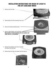
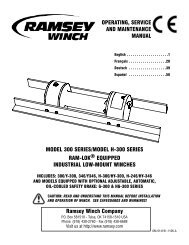
WINCH MOUNTINGESSENTIAL MOUNTING INSTRUCTIONS TO MAINTAIN ALIGNMENT OF PLANETARY WINCH COMPONENTS:It is most important that this winch be mounted securely sothat the three major sections (the motor end, the cabledrum, and the gear housing end) are properly aligned.Excessive bushing wear and difficulty in freespooling areusually symptoms of misalignment.In the as-installed condition, if the winch is mid-mounted,then at least one tie-plate must be attached to the mountingfeet at the bottom of the winch to maintain alignment. If thewinch is foot mounted then at least one tie-plate mustremain mounted at midpoint of winch to maintain alignment.It is always preferred to used BOTH tie-plates in the finalinstalled configuration.Angle Mounting Kit, P/N 251006 (for Std. Drum) or 251007(for “Y” drum), is recommended for maximum ease inmounting the winch. The angle kit will allow the winch to bemounted in upright or midmount applications and will meetthe criteria of serving as a solid and true mounting surface.When mounting the winch with other than the recommended<strong>Ramsey</strong> Angle Kit, the mounting hole patterns described inthe Dimensional drawings on pages 14-15 should be used.The mounting surface must be flat within .015 inch and sufficientlystiff to resist flexing. If a steel plate is used for footmounting, it should be .750 inch thick. For this mountingMID MOUNTTIEPLATE AT FOOT (BASE) LOCATIONapplication eight (8) 1/2-13NC x 1-1/2” long grade 5 capscrews with lockwashers will be needed to mount winch. Capscrews should betightened to 85 ft-lb (115 Nm) torque.NOTE: If angles or a steel plate are used in mounting winch, tie-plates provided with winch are to be attached to the remaining mountingpads, whether they be side or foot.CABLE INSTALLATIONAn “A” or “B” decal on the clutch end bearing indicates the spooling direction of the cable. Also, a letter “A” or “B” is stamped in the endbearing on the clutch end indicating rotation direction. If the decal is damaged or unreadable, contact Customer Service for additionalinstructions to determine proper direction. To reverse the rotation direction, exchange positions of the cartridge and plug shown atright.1. Unwind cable by rolling it out along theground to prevent kinking. Securelywrap end of cable, opposite hook, withplastic or similar tape to prevent fraying.2. Place taped end of cable into hole incable drum as shown below. Use the3/8-16NC x 1/2” long hex socket drivesetscrew (included with drum assemblyitem #1) to secure cable to drum.3. Carefully run winch in the "reel-in" direction.Keeping tension on end of cable,spool all the cable onto the cable drum,taking care to form neatly wrapped layers.After installing cable, check freespool operation.Disengage clutch and pull on cable at awalking speed. If cable “birdnests”, loosenjam nut (item #20) and turn nylon setscrew(item #17) clockwise to increase drag onCAUTION: If longer bolts (minimum grade 5) are substituted to mount winch or tomount a roller guide at the side mount pads, bolt length must be such as to allow aminimum of .50 inch thread length engagement in the tapped holes in side of eachend bearing. Use of excessive length bolts will damage the winch and preventfreespool of the drum. Torque bolts to 55 ft-lbs. (75 Nm).MOTOR ENDFOOT MOUNTINSERT CABLE AS SHOWN FOR "A" ROTATIONOVERWOUND APPLICATION.(UNDERWOUND APPLICATION REQUIRES CABLE TOCOME UNDER DRUM FROM OPPOSITE DIRECTIONAND INSERTED IN THIS SAME CABLE POCKET.)"A" ROTATIONDIRECTIONSETSCREWCABLE DRUMTIEPLATE AT SIDE LOCATION"B" ROTATIONDIRECTIONGEAR HOUSING ENDINSERT CABLE AS SHOWN FOR "B" ROTATIONOVERWOUND APPLICATION.(UNDERWOUND APPLICATION REQUIRES CABLE TOCOME UNDER DRUM FROM OPPOSITE DIRECTIONAND INSERTED IN THIS SAME CABLE POCKET.)drum. If cable pull is excessive, loosen nylon setscrew by turning counterclockwise. Tighten jam nut when proper setting is obtained.CAUTION: OVER-TIGHTENING OF JAM NUT MAY STRIP NYLON SETSCREW.42017