HD-P8000 CE.qxp - Ramsey Winch
HD-P8000 CE.qxp - Ramsey Winch
HD-P8000 CE.qxp - Ramsey Winch
- No tags were found...

Create successful ePaper yourself
Turn your PDF publications into a flip-book with our unique Google optimized e-Paper software.
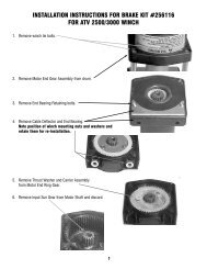
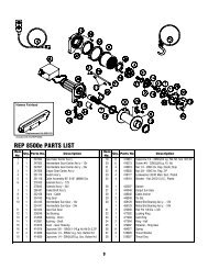
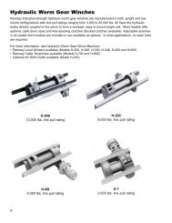
Set winch with gear housing end down on work surface.Install well-oiled o-rings and backup rings into grooves on outside of brake piston and backup brake piston as shown in crosssectionA-A below.Piston, backup piston, brake discs and stators must be clean and free of grease and oil.Insert brake discs (item #4) and stators (item #3) into gear end alternating, with stators first and last.Insert backup brake piston (item #6) into motor end and insert brake piston (item #5) into it. Apply even pressure on pistonwhen installing.Install retaining rings (item #39) into grooves in motor end housing.MOTOR SIDE3129303239A33531283329303264A5SECTION A-A628DRUM SIDE3Insert springs (item #40) into pockets in back of brake piston.The two empty pockets should be on opposite sides.Install roll pin (item #35) into new motor coupling belowbottom of spline teeth. Insert motor coupling (item #23),engaging it with the discs and the input shaft.18Place gasket (item #25) on mounting surfaceof motor (item #27). Slide motor shaft intocoupling. Attach motor to motor end bearinghousing using (2) capscrews (item #18) and(2) lockwashers (item #22). Evenly tighten to49 ft-lbs. (66 Nm) torque.24Install the counterbalance valve (item #42) tothe motor using (4) capscrews (item #14)and (4) lockwashers (item #21). Tighten to17 ft-lbs (23 Nm).Securely connect fittings (item #24) to motorend housing and counterbalance valve, andconnect tube assembly (item #41) to fittings.Apply at least 550 PSI hydraulic system pressureto brake and verify that brake releases(winch drum will rotate).41 42 2114222735242523404510