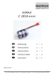
MULTIcont BL 17 - PB Modélisme
MULTIcont BL 17 - PB Modélisme
MULTIcont BL 17 - PB Modélisme
- No tags were found...
Create successful ePaper yourself
Turn your PDF publications into a flip-book with our unique Google optimized e-Paper software.
Anleitung MULITcont <strong>BL</strong>-<strong>17</strong> # 82 5559 (05-10-25/ARRE) • Irrtum und Änderung vorbehalten! •6. PROGRAMMIERUNGDie Programmierung des <strong>MULTIcont</strong> <strong>BL</strong>-<strong>17</strong> ist sehr einfach underfolgt mit Hilfe des Gassteuerknüppels. Pieptöne signalisierenden Status der Programmierung und quittieren Änderungen. Alleveränderbaren Parameter werden Schritt für Schritt durchlaufen.Der Steuerknüppel steht zunächst in Mittelstellung. Die Auswahlder gewünschten Programmieroption erfolgt, indem derSteuerknüppel entweder in Vollgas oder Motor-Aus-Positiongebracht wird. Zurückgehen in Knüppelmittelstellung bestätigtdie Auswahl und führt zum nächsten Parameter.Die Software des <strong>MULTIcont</strong> <strong>BL</strong>-<strong>17</strong> wurde so ausgelegt, dassein unbeabsichtigter Einstieg in den Programmier-Modusunmöglich ist. Dadurch entsteht zunächst der Eindruck, dass esrecht lange dauert, in den Programmiermodus zu gelangen.Doch zu Ihrer Sicherheit soll während der Flugvorbereitungenoder im Flug ein unbeabsichtigter Eintritt in den Programmiermodusverhindert werden.1. Programmiermodus aktivieren1.1 Knüppel in Vollgaspos.1.2 Akku anschließen Initialisierungston(Mehrfachton) ertöntIm LiPo-Modus folgtzusätzlich die Meldungder erkanntenZellenzahl mit 2 oder 3Piepstönen.Danach ertönt einweiterer Mehrfachton1.3 Knüppel in Mittelpos. Quittungston ertönt1.4 Knüppel in Vollgaspos. Quittungston ertönt1.5 Knüppel in Mittelpos. 3-fach Quittungstonertönt, der Reglerbefindet sich nun imProgrammier-modus2. Akkumodus wählen (1-fach Piepton)2.1 für LiPo Knüppel in Vollgaspos.oderfür NiCd/NiMH Knüppel in Motor-AUS-Pos.Bedienungsanleitung <strong>MULTIcont</strong> <strong>BL</strong>-<strong>17</strong> 2 Quittungssignaleertönen2.2 Knüppel in Mittelpos. Quittungston ertönt3. Bremsmodus wählen (2-fach Piepton)3.1 für Bremse EIN 2 Quittungssignale Knüppel in Vollgaspos. ertönenoderfür Bremse AUS Knüppel in Motor-AUS-Pos.3.2 Knüppel in Mittelpos. Quittungston ertönt4. Rotationsrichtung wählen (3-fach Piepton)4.1 für Standard Knüppel in Vollgaspos.oderfür Revers Knüppel in Motor-AUS-Pos. 2 sich wiederholendeQuittungssignaleertönen. Sie zeigen dasEnde derProgrammierung an.Nach diesem letzten Programmierschritt beendet der Regler denProgrammiermodus. Ziehen Sie jetzt den Flugakku ab, ohne denKnüppel noch einmal zu bewegen.Es schadet jedoch nicht, den Knüppel noch einmal in dieMittelstellung zu bringen. Der Motor piepst dann einmaligdreifach und Sie können danach den Akku abziehen.Wenn Sie jetzt den Gasknüppel in Leerlaufstellung bewegenund die Flugbatterie wieder anschließen, ist der Regler mit denneuen Parametern betriebsbereit.7. BEC = BATTERY ELIMINATING CIRCUITBEC bedeutet: Empfänger und Servos werden über den Regleraus dem Antriebsakku mit Strom versorgt. Deshalb: keinenzusätzlichen Empfängerakku verwenden.! Hinweis:Beachten Sie, dass die BEC-Versorgung des <strong>MULTIcont</strong> <strong>BL</strong>-<strong>17</strong>nur kurzzeitig 1,5 A Strom für die Empfangsanlage im Modellabgeben kann.NiCd/NiMH-Zellenzahl 5 - 6 7 - 8 9 - 10LiPo-Zellenzahl 2 - 3Standard (Micro) Servos 4 4 3HighTorque Servos 4 3 2Die Stromaufnahme hängt von der Leistungsklasse der Servos,der Steuerintensität und von der Leichtgängigkeit der Ruderanlenkungen(!) ab.Wenn keine Möglichkeit besteht, den BEC-Strom zu messen:Testlauf am Boden durchführen, Servos bis zur Unterspannungsabschaltung(= leerer Antriebsakku) permanentsteuern. Der Regler darf nicht übermäßig warm werden, dasSteuern der Servos muss während der gesamten Laufzeit ohneAusfallerscheinungen möglich sein!Wenn im Modell mehr Servos vorhanden sind oder ein Flugakkumit mehr als 10 Zellen verwendet wird, muss die BEC-Versorgung unterbrochen und ein zusätzlicher Empfängerakkuverwendet werden.Am Empfängeranschlusskabel des Reglers muss dazu die roteLeitung (+) aufgetrennt werden. Dazu wird das rote Plus-Kabelaus dem Steckergehäuse herausgezogen und mit Schrumpfschlauchisoliert.UnterspannungsabschaltungDie Unterspannungsabschaltung des <strong>MULTIcont</strong> <strong>BL</strong>-<strong>17</strong> sorgtdafür, dass der Antrieb abgeschaltet wird, wenn derAntriebsakku leer wird. Dadurch wird gewährleistet, dass nochgenügend Energie für die BEC-Versorgung für eine sichereLandung zur Verfügung steht und insbesondere LiPo-Akkusnicht zu tief entladen werden.Eine sinkende Drehzahl des Antriebes ist ein weiteresAnzeichen dafür, dass der Antriebsakku leer wird. Die Landungsollte dann eingeleitet werden.Wenn der NiCd/NiMH-Antriebsakku nur noch 5 Volt hat bzw. imLiPo-Modus zwei Zellen unter 6 V oder drei Zellen unter 9 Vabsinken, wird der Regler automatisch abgeschaltet. NachErreichen dieser Abschaltspannung und nachdem der Reglerden Antrieb ausgeschaltet hat, kann der Antrieb jedoch wiederfür kurze Zeit eingeschaltet werden, wenn zuvor der Gasknüppelfür einen Moment in die Leerlauf/Motor-AUS-Stellung gebrachtwurde (Reset-Funktion). Dies sollte man nur ein- bis zweimalwiederholen.8. FEHLERERKENNUNG UND -BEHEBUNGAlles ist richtig angeschlossen, das BEC arbeitet, Servoslaufen, aber die Gasfunktion arbeitet nicht.Wahrscheinlich haben Sie beim Akku anschließen nichtwenigstens 4 Sekunden in Motor-Aus-Position abgewartet undder Regler wurde deshalb nicht scharfgeschaltet.Abhilfe: Bringen Sie den Gasknüppel (incl. Trimmung!) erneutfür mindestens 4 Sekunden in die Motor-AUS.Weiterhin sollten Sie den Servoweg im Sender kontrollieren, ober auf mindestens 100% gesetzt ist. Sollte der Motor dann nichtanlaufen, müssen Sie die Laufrichtung des Gasgebers imSender ändern.MULTIPLEX Modellsport GmbH & Co.KG • Neuer Weg 2 • D-75223 Niefern-Öschelbronn • www.multiplex-rc.de Seite 2/3
Anleitung MULITcont <strong>BL</strong>-<strong>17</strong> # 82 5559 (05-10-25/ARRE) • Irrtum und Änderung vorbehalten! •Jedes Mal, wenn Sie Vollgas geben, schaltet der Regler denMotor nach wenigen Sekunden ab, besonders mit frischgeladener Batterie.Wenn der NiCd/NiMH-Antriebsakku nur noch 5 Volt hat bzw. imLiPo-Modus zwei Zellen unter 6 V oder drei Zellen unter 9 Vabsinken, wird der Regler automatisch abgeschaltet DieseSchaltung verhindert, dass Sie die Steuerfähigkeit durchUnterspannung am Empfänger verlieren. Besonders wenn diesbei vollgeladener Batterie geschieht, deutet es auf zu hoheStromaufnahme des Motors und den dadurch verursachtenstarken Spannungsabfall des Akkus hin. Messen Sie nachMöglichkeit die Stromaufnahme und montieren Sie dannkleinere Propeller oder einen anderen Antriebsakku mit größererKapazität bzw. höherer Strombelastbarkeit.Nichts funktioniert, Empfänger und Servos sowie Reglerzeigen keine Funktion.Überprüfen Sie alle Stecker auf mögliche Wackelkontakte undrichtige Polung (+/-). Wenn danach keine Funktion einsetzt,suchen Sie Ihren Händler auf, der den Regler an Sie verkaufthat, oder senden Sie den Regler an eine MULTIPLEX-Service-Stelle.9. GEWÄHRLEISTUNGSBEDINGUNGENIhr <strong>MULTIcont</strong> <strong>BL</strong>-<strong>17</strong> hat eine Gewährleistungszeit von zweiJahren auf Fehlerfreiheit in Fertigung und Bauteilen abKaufdatum.Die Gewährleistung deckt allerdings nicht die Falschbehandlung,Verpolung, Überstrom- und Überspannungsschädenoder Schäden nach Absturz eines Modells. Fernerhaften wir nicht für Folgeschäden aus dem Gebrauch derRegler.Wenn Sie Fragen haben, Anregungen geben möchten oderIhren <strong>MULTIcont</strong> <strong>BL</strong>-<strong>17</strong> zur Überprüfung oder Reparatureinsenden wollen, wenden Sie sich an:In Europa:MULTIPLEX KundendienstNeuer Weg 15 • D-75223 Nieferne-mail: service@multiplexrc.deTel.: ++49 (0)7233-7333oder an eine andere MULTIPLEX-ServicestelleAdressen siehe www.multiplex-rc.deIn USA:MULTIPLEX USA12115 Paine St. • Poway, CA. 92064Tel: (858) 748-6948 • Fax: (878) 748-<strong>17</strong>67Email: service@hitecrcd.comInfo: www.multiplexusa.com10. CE-PRÜFUNGDie beschriebenen Produkte genügen allen einschlägigen undzwingenden EG-Richtlinien.Dies sind die EMV-Richtlinien 89/336/EWG, 91/263/EWG und92/31/EWG.Der Regler wurden nach folgenden Fachgrundnormen geprüft:Störaussendung: EN 50 081-1:1992Störfestigkeit: EN 50 082-1:1992bzw. EN 50 082-2:1995Sie besitzen daher ein Produkt, dass hinsichtlich derKonstruktion die Schutzziele der Europäischen Gemeinschaftzum sicheren Betrieb der Geräte erfüllt.Bedienungsanleitung <strong>MULTIcont</strong> <strong>BL</strong>-<strong>17</strong>11. ENTSORGUNGSHINWEISEElektrogeräte, die mit der durchgestrichenen Mülltonnegekennzeichnet sind, zur Entsorgung nicht in den Hausmüllgeben, sondern einem geeigneten Entsorgungssystemzuführen.In Ländern der EU (Europäische Union) dürfenElektrogeräte nicht durch den Haus- bzw. Restmüllentsorgt werden (WEEE - Waste of Electrical andElectronic Equipment, Richtlinie 2002/96/EG). Siekönnen Ihr Altgerät bei öffentlichen SammelstellenIhrer Gemeinde bzw. ihres Wohnortes (z.B.Reycyclinghöfe) abgeben. Das Gerät wird dort fürSie fachgerecht und kostenlos entsorgt.Mit der Rückgabe Ihres Altgerätes leisten Sie einen wichtigenBeitrag zum Schutz der Umwelt!MULTIPLEX Modellsport GmbH & Co.KG • Neuer Weg 2 • D-75223 Niefern-Öschelbronn • www.multiplex-rc.de Seite 3/3
Instructions - MULITcont <strong>BL</strong>-<strong>17</strong> # 82 5559 (05-10-25/ARRE) • Errors and omissions e ce ted •Operating instructions - <strong>MULTIcont</strong> <strong>BL</strong>-<strong>17</strong>! These operating instructions are an integral part of thisproduct. They contain important information and safety notes,and should therefore be kept in a safe place at all times. Be sureto pass them on to the new owner if you ever dispose of theproduct.1. SPECIFICATION<strong>MULTIcont</strong><strong>BL</strong>-<strong>17</strong>Order No.: 7 2274Cell count:5 - 12 NiCd / NiMH2 - 3 Li-PoContinuous / peak current:<strong>17</strong> A / max. 22 AInternal resistance:0.013 OhmPulse frequency:~ 13 kHzReceiver power supply (BEC) with up to 10 cellsBEC voltage:5 VBEC current:max. 1.5 ADimensions:26 x <strong>17</strong> x 8 mmWeight:9 g incl. cables2. SAFETY NOTES! Read the instructions before using the controller.! Avoid heat build-up:Provide unobstructed air circulation round the controller.! Do not connect the flight battery with reversed polarity:Connecting the battery leads with reversed polarity willinstantly wreck the controller.For this reason: • red wire to the POSITIVE terminal ( + ),• black wire to the NEGATIVE terminal ( - )! When soldering or working on the motor or controller:Always disconnect the battery (short-circuit / injury hazard)! When testing and running the power system:Do not run the motor while holding it in your hand; alwayssecure the model firmly. Check that there is adequate spacefor the propeller to rotate. Remove all objects from the areaaround the propeller which could be sucked in or blown away(clothing, paper etc.). Never stand in the rotational plane ofthe propeller (injury hazard).3. SPECIAL FEATURESProgrammable brake for folding propellersESC with low voltage cut-off and reset function for Li-Po andNiCd / NiMH cellsImmediate motor cut if transmitter signal fails, or interferenceoccursPower-on guard prevents motor bursting into life when theflight battery is connectedMotor can be run in either direction4. WIRING THE MULTICONT <strong>BL</strong>-<strong>17</strong>! Note:Soldering is usually required in order to complete the wiring ofthe controller. Soldering requires some care, as the quality of thejoints is crucial to the reliability of the power system: use electronic-grade solder for all soldered joints do not use acid-based solder flux parts to be soldered must be hot enough (the solder mustflow), but must not be overheated (damage to components) if you are unsure, ask a modeller with experience insoldering to help youAttaching the battery connectorsThe battery connectors must be soldered to the wires at the endof the controller which features just two wires and the three-corereceiver lead. If necessary, cut down the wires at the battery endto the correct length. Take great care to maintain correct polaritywhen attaching the connectors. Fit individual heat-shrink sleevesover each soldered joint to provide thorough insulation.! Important note:You must be absolutely certain that the polarity is correct! If youmake a mistake here, the controller will instantly be ruined.Connecting the controller to the motorThe motor must be connected to the wires at the end of thecontroller which features three wires. Keep the controller wiresas short as possible, but do not shorten the wires attached to themotor! Strip the end of the controller wires (to the motor) so thatyou can solder the joints easily. When you have established thecorrect direction of rotation, and no further soldering is required,insulate each soldered joint separately with a heat-shrink sleeve.Reversing the direction of motor rotationIf the motor spins in the wrong direction, simply swap over anytwo of the three wires running to the motor terminals. If you donot wish to do this, please note that it is also possible to reversethe motor direction using the programming procedure ( 6.1.4.).5. USING THE CONTROLLER FOR THE FIRST TIME1. Connecting the controller’s receiver lead (BEC) to thereceiverConnect the servo lead attached to the controller to thereceiver socket corresponding to the throttle channel:for example, with all MULTIPLEX radio control systems thisis channel 4 = throttle / motorNegative pin () black (brown)Positive pin (+)redSignal ( ) yellow (orange)Do not connect a separate receiver battery, as the<strong>MULTIcont</strong> <strong>BL</strong>-<strong>17</strong> supplies electrical current to the receiver(and the servos connected to it) via the BEC system.2. If your radio control system is programmable, set servotravel for throttle / motor to 100% on both sides.3. Move the throttle stick (and the associated trim) on thetransmitter to the idle end-point, or motor STOPPED. Note:you may need to reverse the servo direction of the throttlechannel; see the Fault-Finding section.4. Switch on the transmitter5. Connect the flight battery to the speed controllerBy default the <strong>MULTIcont</strong> <strong>BL</strong>-<strong>17</strong> is in Li-Po mode. You willhear an initialisation beep, followed by two or three beepswhich indicate the number of battery cells the controller hasdetected (see BEC / low-voltage cut-off ( 7.)).After this the controller emits a single beep every 30 secondswhen at idle; this is intended to remind you that your model isswitched on. If you are using NiCd or NiMH cells, pleasefollow the programming instructions ( 6.1.2.).By default the brake is switched off, because this is preferredfor most 3D and park-fly models. If you wish to activate thebrake (generally because the controller is required to workwith a folding propeller), please follow the programminginstructions ( 6.1.3.).The <strong>MULTIcont</strong> <strong>BL</strong>-<strong>17</strong> also allows you to reverse thedirection of motor rotation “electronically”. If you wish to dothis, please follow the programming instructions ( 6.1.4.).MULTIPLEX Modellsport GmbH & Co.KG • Neuer Weg 2 • D-75223 Niefern-Öschelbronn • www.multiplex-rc.de Page 1/3
Instructions - MULITcont <strong>BL</strong>-<strong>17</strong> # 82 5559 (05-10-25/ARRE) • Errors and omissions excepted •6. PROGRAMMINGOperating instructions - <strong>MULTIcont</strong> <strong>BL</strong>-<strong>17</strong>7. BEC = BATTERY ELIMINATING CIRCUITProgramming the <strong>MULTIcont</strong> <strong>BL</strong>-<strong>17</strong> is very simple, and iscarried out using the throttle stick. Audible beeps indicate thestatus of the programming procedure, and confirm any changesthat you make. The process cycles through all the variableparameters step by step. Initially the throttle stick should be leftat the centre position. The desired programming options areselected by moving the stick either to the full-throttle or themotor OFF position. Moving the stick back to centre confirmsyour selection, and moves on to the next parameter.The software of the <strong>MULTIcont</strong> <strong>BL</strong>-<strong>17</strong> has been designed tomake it impossible to switch to programming mode accidentally.This initially gives the impression that it takes a very long time toswitch to programming mode, but this is intentional: for your ownsafety it is essential that you cannot enter programming mode bymistake when you are preparing to fly, or actually flying.1. Activating programming mode1.1 Stick to full-throttle position1.2 Connect battery Controller emitsmultiple initialisationbeep. In Li-Po mode 2or 3 beeps are emittedto indicate the numberof cells detected.A further multiple beepis then emitted.1.3 Stick to centre position Confirmation beep1.4 Stick to full-throttle position Confirmation beep1.5 Stick to centre position Triple confirmationbeep; controller is nowin programming mode2. Select battery mode (single beep)2.1 for Li-Po stick to full-throttle positionorfor NiCd / NiMH stick to motor OFF position Two confirmationsignals2.2 Stick to centre position. Confirmation beep3. Select brake mode (double beep)3.1 for brake ON Two confirmation stick to full-throttle position signalsorfor brake OFF stick to motor OFF position3.2 Stick to centre position. Confirmation beep4. Select direction of rotation (triple beep)4.1 for default direction stick to full-throttle positionorfor reverse direction stick to motor OFF position Two repeatedconfirmation beeps,indicating the end of theprogramming process.When the last programming step is finished, the controllerterminates programming mode. Now disconnect the flight batterywithout moving the stick again.However, it does no harm to move the stick back to the centreposition. If you do this, the motor emits three single beeps, andyou can disconnect the battery.Move the throttle stick to the idle position and re-connect theflight battery. The speed controller is now ready for use with thenewly set parameters.BEC means: the controller supplies electrical current to thereceiver and servos from the flight battery. For this reason: donot use a separate receiver battery.! Note:Please note that the <strong>MULTIcont</strong> <strong>BL</strong>-<strong>17</strong>’s BEC circuit is onlycapable of supplying a peak of 1.5 A of current for the model’sairborne receiving system.NiCd / NiMH cell count 5 - 6 7 - 8 9 - 10Li-Po cell count 2 - 3Standard (micro) servos 4 4 3High-torque servos 4 3 2The current drain varies according to the power of the servos,the frequency of control commands and the stiffness of thecontrol surface linkages (!).If you do not have any means of measuring the BEC current, werecommend that you carry out a ground-check by operating theservos continuously until the battery is flat (low-voltage cut-offtriggered). The controller must not become more than warm tothe touch during this test, and the servos must respond correctlyto stick movements without any sign of failure.If your model carries more servos than specified, or you wish touse a flight battery with more than 10 cells, the BEC circuit mustbe disabled, and a separate receiver battery installed.The BEC system is disabled by disconnecting the red (+) wire inthe lead. Withdraw the red positive wire from the plug housing,and insulate the contact with a heat-shrink sleeve.Low-voltage cut-offThe <strong>MULTIcont</strong> <strong>BL</strong>-<strong>17</strong>’s low-voltage cut-off circuit switches offthe motor in the model when the flight battery is discharged. Thisensures that the battery maintains adequate energy reserves forthe BEC system, so that a safe landing can be carried out. Italso ensures that Li-Po batteries are not discharged too far.Another indication that the flight battery is almost discharged isdeclining motor power (propeller speed). When you notice this, itis time to prepare for the landing approach.The controller automatically switches off the motor when theNiCd / NiMH flight battery voltage falls to 5 Volts; in Li-Po modethe bottom limit is 6 V (two cells) or 9 V (three cells). If thebattery reaches this trigger voltage and the controller switchesoff the motor, you can switch it on again briefly (to enable you toreach the landing area) by moving the throttle stick to the idle /motor OFF position for a moment, then advancing it again(Reset function). This should only be carried out once or twice.8. FAULT-FINDING, FAULT ELIMINATIONEverything is connected correctly, the BEC system works,the servos operate, but the throttle function does not work.The most likely problem is that you did not wait the minimumfour seconds in the motor OFF position after connecting thebattery, so the controller is not “armed”.Remedy: move the throttle stick (and trim!) back to motor OFFand leave it there for at least four seconds.You should also check servo travel at the transmitter: it must beset to at least 100%. If the motor still does not respond to thethrottle stick, you must reverse the direction of the throttlechannel control at the transmitter.Every time you apply full-throttle, the controller switches offthe motor after a few seconds. This happens in particularwhen you connect a freshly charged battery.MULTIPLEX Modellsport GmbH & Co.KG • Neuer Weg 2 • D-75223 Niefern-Öschelbronn • www.multiplex-rc.de Page 2/3
Instructions - MULITcont <strong>BL</strong>-<strong>17</strong> # 82 5559 (05-10-25/ARRE) • Errors and omissions excepted •Operating instructions - <strong>MULTIcont</strong> <strong>BL</strong>-<strong>17</strong>If the voltage of the NiCd / NiMH flight battery falls to 5 Volts, orif in Li-Po mode it falls below 6 V (two cells) or 9 V (three cells),the controller automatically switches off the motor. This circuit isdesigned to avoid loss of control of the receiver due to lowvoltage. If this should occur with a fully charged battery, this is asure indication that the motor is drawing an excessive current,which is causing the voltage of the battery to fallto a dangerous level. If possible, measure thecurrent drain, and - if necessary - fit a smallerpropeller, or a different flight battery with greatercapacity or better capability of delivering highcurrents.Nothing works; receiver, servos and speedcontroller dead.Check all electrical connections for possible intermittent contactand correct polarity (+/-). If the system still fails to work, take thecontroller back to the model shop where you purchased it, orsend it to your nearest MULTIPLEX Service Centre.9. GUARANTEE CONDITIONSYour <strong>MULTIcont</strong> <strong>BL</strong>-<strong>17</strong> is guaranteed to be free ofmanufacturing and material defects for a period of two yearsfrom the date of purchase.The guarantee does not cover incorrect handling, reversedpolarity, damage due to excessive current, excessive voltage, orthe crash of a model. We will not consider claims for damageconsequent to the use of the speed controller.If you have queries or ideas, or wish to send your <strong>MULTIcont</strong><strong>BL</strong>-<strong>17</strong> to us for repair or for any other reason, please contact usat:In Europe:MULTIPLEX Customer Service Dept.Neuer Weg 15 • D-75223 Nieferne-mail: service@multiplexrc.deTel.: ++49 (0)7233-7333or to any other MULTIPLEX Service CentreSee www.multiplex-rc.de for addressesIn USA:MULTIPLEX USA12115 Paine St. • Poway, CA. 92064Tel: (858) 748-6948 • Fax: (878) 748-<strong>17</strong>67Email: service@hitecrcd.comInfo: www.multiplexusa.com10. CE APPROVALThe products described in these instructions satisfy all currentand statutory EU directives.These are the EMV directives 89/336/EEC, 91/263/EEC and92/31/EEC.The controller has been tested in accordance with the followingbasic norms:Interference emission: EN 50 081-1:1992Interference rejection: EN 50 082-1:1992and EN 50 082-2:1995You therefore own a product whose design and constructionfulfil the aims of the European Community in respect of the safeoperation of equipment.11. DISPOSAL INFORMATIONElectrical equipment marked with the crossed-out refuse binmust not be discarded in the household waste; it must be takento a suitable collection point for proper disposal.In the countries of the EU (European Union) it is illegal todispose of electrical devices via the household waste system(WEEE - Waste of Electrical and Electronic Equipment, directive2002/96/EC). You can take your unwanted equipment to yourlocal public collection point (e.g. recycling centre), which willdispose of it in the correct manner at no cost to you.By recycling your unwanted equipment you can make animportant contribution to the protection of the environment.MULTIPLEX Modellsport GmbH & Co.KG • Neuer Weg 2 • D-75223 Niefern-Öschelbronn • www.multiplex-rc.de Page 3/3
Notice d’utilisation MULITcont <strong>BL</strong>-<strong>17</strong> # 82 5559 (05-10-25/ARRE) • sous réserve de toute erreur ou modification! • MULTIPLEX! Ces instructions font partie intégrante du produit. Cellecicontient des informations importantes ainsi que desconsignes de sécurités. Elle doit donc être consultable àtous moments et à joindre lors d’une revente à tiercepersonne.1. DONNEES TECHNIQUES<strong>MULTIcont</strong><strong>BL</strong>-<strong>17</strong>Nr. Com.: 7 2274Nbr. d’éléments:5 - 12 NiCd/NiMH2 - 3 LiPoCourant continu/de pointe:<strong>17</strong> A / max. 22 ARésistance interne:0,013 OhmFréquence de fonctionnement:~ 13 kHzAlimentation du récepteur (BEC) jusqu’à 10 élémentsTension BEC:5 VCourant BEC:max. 1,5 ADimensions:26 x <strong>17</strong> x 8 mmPoids:9 g avec les câbles2. CONSIGNES DE SECURITE! Lire les instructions avant la mise en marche! Evitez l’accumulation de chaleur:Garantissez une bonne circulation d’air autour du régulateur.! Ne pas inverser la polarité de l’accu:Une inversion des polarités détruirait instantanément lerégulateur.D’où: • fil rouge sur la cosse POSITIVE ( + ),• fil noir sur la cosse NEGATIVE ( - )! Pour tous travaux de soudures ou d’assemblages auniveau de la propulsion ou du régulateur:Toujours débrancher l’accu (Court-circuit/Danger corporel!)! Pendant les essais ou en fonctionnement normal:Ne pas tenir le moteur en marche dans la main, bien fixer lemodèle. Vérifier si vous avez suffisamment de place pour larotation de l’hélice. Enlever des environs de l’hélice tous lesobjets qui seraient sujet à une aspiration (vêtement, petitespièces, papier, etc.). Ne vous tenez jamais devant l’hélice ouau niveau du plan de rotation de celle-ci (dangerscorporels !).3. PROPRIETES PARTICULIERES Fonction freinage réglable pour les hélices repliables ESC avec système de coupure automatique de l’alimentationpar sous-tension et fonction Reset pour les éléments LiPo ouNiCd/NiMH Arrêt automatique du moteur dans le cas de perte de signald’émetteur ou de perturbations Le système de sécurité à l’allumage empêche le démarrageintempestif du moteur lorsque vous connectez l’accu Le moteur peut tourner dans les deux sens4. BRANCHEMENT DU MULTICONT <strong>BL</strong>-<strong>17</strong>! Remarque:Pour le montage du régulateur il est nécessaire d’effectuerquelques soudures qui demandent un minimum de rigueur. Eneffet, de celle-ci dépend le bon fonctionnement de l’ensemble, etpour cela il faut : n’utiliser que de l’étain utilisé en assemblage de cartesélectroniques ne pas utiliser de graisse de soudure à base de produitsacidesNotice d’utilisation <strong>MULTIcont</strong> <strong>BL</strong>-<strong>17</strong>MULTIPLEX Modellsport GmbH & Co.KG • Neuer Weg 2 • D-75223 Niefern-Öschelbronn • www.multiplex-rc.de Seite 1/3ne pas trop chauffer, mais suffisamment, les parties à souder(l’étain doit fondre)demander conseil ou de l’aide à une personne du métierBranchement du connecteur d’accuLes conducteurs du connecteur pour l’accu se soudent du côtédu régulateur où débouchent 2 câbles ainsi que le câble 3 fils deconnexion au récepteur. Réduisez les câbles d’alimentation, ducôté accu, à la longueur nécessaire. Veillez à respecter lapolarité de l’accu lors de l’opération de soudage. Isolezsoigneusement les soudures avec de la gainethermorétractable.! Remarque importante:Vous devez vous assurer que la polarité soit correcte!! Uneinversion de polarité entraîne assurément une destructiondirecte du régulateur!Branchement du régulateur au moteurLe moteur est connecté sur les 3 câbles sortant de côté.Raccourcissez au minimum les câbles d’alimentation du côté durégulateur, surtout pas du côté moteur! Dénudez les câblesreliant le moteur au régulateur de telle manière à pouvoirassurer une bonne soudure des trois câbles vers le moteur. Unefois que le sens de rotation a été vérifié et toutes les souduresont été effectuée proprement, isolez définitivement l’ensembleavec de la gaine thermorétractable.Inversion du sens de rotationSi vous avez besoin de changer le sens de rotation de votremoteur, inversez simplement deux des trois câbles allant aumoteur. Une autre possibilité serait de changer laprogrammation sur votre radiocommande ( 6.1.4.).5. MISE EN MARCHE1. Connecter le câble de liaison (REC) du régulateurau récepteurConnectez le câble de servo de votre régulateur sur la sortiecorrespondante à la fonction moteur de votre récepteur:Pour toutes les radio MULTIPLEX, le canal 4= Gaz/MoteurPôle Moins ()Noir (brun)Pôle Plus (+)rougeImpulsion ( ) jaune (orange)Ne branchez pas d’accu de réception du fait que le<strong>MULTIcont</strong> <strong>BL</strong>-<strong>17</strong> alimente le récepteur à travers sa fonctionBEC.2. Pour les radios programmables, régler le débattement duservo Gaz/Moteur à 100% pour les deux sens.3. Placer le manche des Gaz (ainsi que leur Trimm!) del’émetteur complètement dans la position ralenti/ArrêtMoteur souhaitée (si nécessaire, inversez le sens derotation de la fonction gaz, voir au chapitre reconnaissanced’erreur et rectification)4. Mise en marche de l’émetteur5. Connecter l’accu de propulsion au régulateurEn sortie d’usine, le <strong>MULTIcont</strong> <strong>BL</strong>-<strong>17</strong> se trouve en modeLiPo. Après le signal sonore d’initialisation, le système vaémettre deux ou trois signaux sonores en fonction dunombre d’éléments qui sont reconnus par le régulateur (voirBEC/Arrêt par sous-tension ( 7.).Ensuite, en position ralentie, vous entendrez toutes les 30secondes un signal sonore. Celui-ci vous rappelle que votremodèle est allumé. Si vous utilisez des éléments NiCd ouNiMH, suivez les instructions de programmations ( 6.1.2.)En sortie d’usine, la fonction frein est désactivée du fait quecela est préconisé pour les modèles 3D et Parkfly. Si voussouhaitez activer la fonction frein, parce que vous vous avezun modèle avec hélice repliable, suivez les instructions deprogrammations ( 6.1.3.).
Notice d’utilisation MULITcont <strong>BL</strong>-<strong>17</strong> # 82 5559 (05-10-25/ARRE) • sous réserve de toute erreur ou modification! • MULTIPLEXAvec le <strong>MULTIcont</strong> <strong>BL</strong>-<strong>17</strong> vous pouvez également inverserle sens de rotation du moteur d’une manière „électronique“.Pour cela suivez les instructions de programmation (6.1.4.).6. PROGRAMMATIONLa programmation de votre <strong>MULTIcont</strong> <strong>BL</strong>-<strong>17</strong> est vraiment trèssimple à l’aide du manche des gaz de votre radiocommande.Des signaux sonores vous donnent l’état de la programmation etvalident des modifications. Tous les paramètres modifiables sontactivés tour à tour. Le manche est tout d’abord en positioncentrale. La sélection de l’option de programmation souhaitée sefera en positionnant le manche des gaz soit en position ralenti(arrêt moteur) ou pleine puissance. Replacer le manche enposition centrale confirme votre choix et vous fait passer auprochain paramètre.Le programme du <strong>MULTIcont</strong> <strong>BL</strong>-<strong>17</strong> a été conçu de tellemanière à ce que l’on ne peut pas accéder au modeprogrammation par erreur. Dans un premier temps cela vousdonne l’impression que l’accès à la programmation sera trèslong. Mais, pour votre sécurité, il est préférable que vous nepuissiez pas accéder dans le mode programmation pendant lapréparation du vol ou pendant le vol.1. Activation du mode programmation1.1 Manche en position pleinepuissance.1.2 Branchez votre accu Signal d’initialisation(plusieurs bips sonores).Dans le mode LiPo vousaurez tout d’abordl’indication du nombred’éléments reconnusavec deux ou trois bipssonores.Ensuite suivrons ànouveau plusieurssignaux sonores1.3 Manche en position centrale. Signal sonore dequittance1.4 Manche en position plein gaz. Signal sonore dequittance1.5 Manche en position centrale. 3 bip sonores, lerégulateur se trouve enmode programmation2. Sélection du mode accu (1 bip sonore)2.1 pour les accus LiPo manche en position centrale.oupour les accus NiCd/NiMH manche en position ralenti.Notice d’utilisation <strong>MULTIcont</strong> <strong>BL</strong>-<strong>17</strong> 2 bip sonores dequittance2.2 Manche en position centrale. Signal sonore dequittance3. Sélection du mode de freinage (2 bips sonores)3.1 pour activer le frein (ON) manche en pleine puissanceoupour désactiver le frein (OFF) manche en position ralenti 2 bips sonores dequittance3.2 Manche en position centrale Signal sonore dequittance4. Choix du sens de rotation (3 bips sonores)4.1 Pour le sens standard manche en pleine puissanceoupour le sens inverse manche en position ralenti 2 bips sonores sesuivants. Ils indiquent lafin de la programmationAprès ce dernier pas de programmation, le régulateur sortautomatiquement du mode programmation. Débranchez l’accude propulsion sans bougez le manche.Néanmoins, il est conseillé de replacer le manche en positioncentrale. A ce moment la, le moteur émet un triple signal sonoreet, ensuite, vous pouvez débrancher l’accu.Maintenant, si vous placez le manche des gaz en position ralentiet que vous rebranchiez l’accu de propulsion, le régulateur estprès à l’utilisation avec les nouveaux paramètres.7. BEC = BATTERY ELIMINATING CIRCUITBEC signifie: récepteur et servos sont alimentés par l’accu depropulsion à travers le régulateur. De ce fait, aucun accu deréception supplémentaire n’est nécessaire.! Remarque: attention, l’alimentation BEC du <strong>MULTIcont</strong> <strong>BL</strong>-<strong>17</strong>ne peut délivrer que peu de temps un courant de 1,5 A pour lapartie réception dans le model.Nbr d’élém. NiCd/NiMH 5 - 6 7 - 8 9 - 10Nbr d’élém. LiPo 2 - 3Servo standard (Micro) 4 4 3Servo HighTorque 4 3 2La consommation de courant dépend de la gamme depuissance des servos, de l’intensité des commandes et de lalégèreté des mouvements des tringles de commandes desgouvernes (!).Si vous n’avez pas la possibilité de mesurer le courant BEC:Effectuez un test de fonctionnement au sol et bougez enpermanence les servos jusqu'à ce que le système de protectionde sous-tension (= accu déchargé). Le régulateur ne doit pastrop chauffer, la réponse des servos ne devra donner aucunsigne de perturbation ou de mal fonctionnement tout au long dutest!Si vous utilisez plus de servos que le système ne support, ou unaccu de propulsion de plus de 10 éléments, vous devezdésactiver l’alimentation BEC et utiliser un accu de réceptionsupplémentaire.Pour cela vous devez couper le fil rouge (+) du câble durégulateur allant sur le récepteur. Pour cela, vous pouvezsimplement sortir la fiche du connecteur et l’isoler avec du rubanadhésif isolant.Système de protection de sous-tensionLe système de protection de sous-tension de votre <strong>MULTIcont</strong><strong>BL</strong>-<strong>17</strong> fait en sorte de couper l’alimentation de la propulsionlorsque l’accu se vide. Par ce biais il est garanti de conserversuffisamment d’énergie pour pouvoir alimenter le système deradiocommande par le système BEC afin d’assurer un bonatterrissage et, pour ne pas décharger les accus LiPo endessous de leur seuil minimal.La chute du nombre de tours minutes de la propulsion est unautre signe que l’accu se vide. Il est conseillé d’effectuer unerecharge de celui-ci.Si l’accu de propulsion NiCd/NiMH n’a plus que 5 Volts ou, enmode LiPo, celui-ci soit en dessous de 6 V pour deux élémentsLiPo et en dessous de 9 V pour trois éléments LiPo, lerégulateur coupe automatiquement la propulsion. Après avoiratteint se seuil et après que le régulateur ait coupé la propulsion,vous pouvez faire redémarrer celle-ci pour peu de temps si vousavez remis le manche des gaz en position ralenti/OFF (fonctionreset). Manipulation à n’effectuer qu’une ou deux fois maximum.8. RECONNAISSANCE D’ERREUR ET CORRECTIONMULTIPLEX Modellsport GmbH & Co.KG • Neuer Weg 2 • D-75223 Niefern-Öschelbronn • www.multiplex-rc.de Seite 2/3
Notice d’utilisation MULITcont <strong>BL</strong>-<strong>17</strong> # 82 5559 (05-10-25/ARRE) • sous réserve de toute erreur ou modification! • MULTIPLEXTout est bien branché, le système BEC travail bien, lesservos répondent correctement, mais la fonction gaz nerépond pas.Vous n’avez sûrement pas attendu les 4 secondes avec lemanche des gaz en position ralenti lorsque vous avez branchél’accu de propulsion, de ce fait le régulateur n’a pas été activé.Remède: replacez le manche des gaz à nouveau en positionralenti/moteur OFF (ainsi que le trim!) pour plus de 4 secondes.De plus, contrôlez la course programmée sur votre radio,assurez vous que celle-ci soit de 100%. Si votre moteur nedémarre toujours pas, inversez la course de la commandemoteur sur l’émetteur.A chaque fois que je mets la pleine puissance, le régulateurcoupe la propulsion après quelques secondes, surtout avecdes accus fraîchement chargés.Si votre accu de propulsion NiCd/NiMH n’a plus que 5 Volt, ouque les deux éléments LiPo soient sous 6 V ou encore les troiséléments sous 9 V, alors le régulateur coupe automatiquementla propulsion. Ce système empêche que vous perdiez lecontrôle de votre modèle à cause d’une sous alimentation durécepteur. Surtout si ce cas ce présente pour des accucomplètement chargés, cela signifie une consommation decourant trop élevée du moteur et, de ce fait, une chute detension trop importante de l’accu. Si vous en avez la possibilité,mesurez la consommation de courant puis équipez votre moteurd’hélices de plus en plus petites ou utilisez des accus depropulsions de plus grande capacité et donc pouvant délivrerplus de puissance.Rien ne fonctionne, ni le récepteur, ni les servos, ni lerégulateur ne montre un signe de vie.Vérifiez sur tous les connecteurs s’il n’y aurait pas un problèmede contact et si la polarité a bien été respectée (+/-). Si aprèscela ne fonctionne toujours pas, rapportez le régulateur chez lerevendeur chez lequel vous l’avez acheté ou envoyez celui-ciauprès d’une de nos stations MULTIPLEX.9. ONDITIONS DE GARANTIESVotre régulateur <strong>MULTIcont</strong> <strong>BL</strong>-<strong>17</strong> est garanti pendant deux anspour tous problèmes de fabrication ou de composants à partir dela date d’achat.Celle-ci n’est pas valable dans le cas d’une mauvaise utilisationde votre régulateur, inversion de polarité, surchargecourant/tension ou après un crash de votre modèle. De plus,nous ne sommes aucunement responsable des conséquencesde l’utilisation que vous faite avec ce régulateur.Si vous avez des questions, des suggestions ou si voussouhaitez nous envoyer votre <strong>MULTIcont</strong> <strong>BL</strong>-<strong>17</strong> pour unerévision ou une réparation, adressez vous à:En Europe:MULTIPLEX Kundendienst (service après vente)Neuer Weg 15 • D-75223 Nieferne-mail: service@multiplexrc.deTel.: ++49 (0)7233-7333Ou à toute autre adresse de nos stations services MULTIPLEXque vous pouvez trouver sur notre page internet www.multiplexrc.deEn USA:MULTIPLEX USA12115 Paine St. • Poway, CA. 92064Tel: (858) 748-6948 • Fax: (878) 748-<strong>17</strong>67Email: service@hitecrcd.comInfo: www.multiplexusa.com10. CERTIFICATION CENotice d’utilisation <strong>MULTIcont</strong> <strong>BL</strong>-<strong>17</strong>Tous nos produits décrits ci-dessus respectent les directives etles obligations fixées par la communauté Européenne.Ce sont les directives EMV 89/336/EWG, 91/263/EWG et92/31/EWG.Le régulateur a été testé suivant les textes de normes suivants:Emissions parasites: EN 50 081-1:1992Sensibilité au bruit: EN 50 082-1:1992ou EN 50 082-2:1995De ce fait, vous êtes en possession d’un appareil qui est garanticonforme d’un point de vue construction auxdirectives européennes de sécurités.11. REMARQUES POUR LE RECYCLAGEIl ne faut surtout pas jeter les appareils électroniques portantcette étiquette avec une poubelle barrée, dans une poubelled’ordure ménagère mais les amener à un point de recyclage devotre région.Dans les pays de l’union européenne il est interdit de jeter lesappareils électroniques dans les poubelles collectives ouménagères (WEEE - Waste of Electrical and ElectronicEquipment, directives 2002/96/EG). Vous pouvez apporter votreancien appareil électronique à la déchetterie de votre communeou de votre quartier. L’appareil y sera recyclé gratuitement etprofessionnellement.En rapportant votre ancien appareil, vous participez activementà la protection votre environnement!MULTIPLEX Modellsport GmbH & Co.KG • Neuer Weg 2 • D-75223 Niefern-Öschelbronn • www.multiplex-rc.de Seite 3/3
Manual de Instrucciones del MULITcont <strong>BL</strong>-<strong>17</strong> # 82 5559 (05-10-25/ARRE) • ¡Todos los derechos reservados! • MULTIPLEX6. PROGRAMACIÓNLa programación del <strong>MULTIcont</strong> <strong>BL</strong>-<strong>17</strong> es realmente fácil y selleva a cabo usando la palanca del gas. Los pitidos muestran elestado de la programación e indican los cambios realizados. Sehará un recorrido, paso a paso, por todos los puntosprogramables. Inicialmente la palanca del gas debe estar en elpunto neutro. La selección de la opción a programar se lleva acabo con la palanca del gas, dependiendo de la posición deesta, al ralentí o a todo gas. Volviendo a poner la palanca en suposición central se confirma la programación y se salta alsiguiente punto.La programación del <strong>MULTIcont</strong> <strong>BL</strong>-<strong>17</strong> está diseñada para quesea imposible entrar al modo de programación accidentalmente.Por ello, puede darle la impresión que el entrar en el modo deprogramación tarda demasiado. Esto evitará que durante lospreparativos al vuelo, o durante éste, se entre en modo deprogramación sin desearlo.1. Activación del modo de programación1.1 Palanca del gas a tope.1.2 Conecte la batería Suena el tono deinicialización (múltiple)En modo LiPo leseguirán 2 o 3 pitidosdependiendo delnúmero de elementos.Serán seguidos delpitido múltiple1.3 Palanca del gas en neutro. Tono de confirmación1.4 Palanca del gas a tope. Tono de confirmación1.5 Palanca del gas en neutro. 3 tonos deconfirmación, elregulador ha entrado enmodo programación2. Selección del tipo de baterías (1 pitido)2.1 para LiPo Palanca del gas a tope.opara NiCad/NiMH Palanca del gas al ralentí.Instrucciones del <strong>MULTIcont</strong> <strong>BL</strong>-<strong>17</strong>7. BEC = BATTERY ELIMINATING CIRCUIT 2 pitidos deconfirmación2.2 Palanca del gas en neutro. Tono de confirmación3. Selección de frenado (Pitido doble)3.1 Frenos ACTIVADOS 2 tonos de Palanca del gas a tope. confirmaciónoFrenos DESACTIVADOS Palanca del gas al ralentí.3.2 Palanca del gas en neutro. Tono de confirmación4. Sentido del giro del motor (Pitido triple)4.1 Standard Palanca del gas a tope.oInvertido Palanca del gas al ralentí. 2 tonos deconfirmaciónrepitiéndose. Indica quese ha llegado al final dela programación.Tras este último paso el programador da por finalizado el modode programación. Desconecte la batería, sin mover la palancadel gas.No se preocupe si vuelve a poner la palanca en el punto neutro.El motor emitirá tres pitidos y podrá desconectar la batería.Si vuelve a poner ahora la palanca al ralentí y conecta d nuevola batería, el regulador estará listo para funcionar con la nuevaprogramación.BEC significa: El receptor y los servos se alimentan de labatería del motor. Por tanto, no es necesario usar una bateríaadicional.! Aviso:Tenga en cuenta, que la alimentación BEC del <strong>MULTIcont</strong> <strong>BL</strong>-<strong>17</strong> sólo es capaz de entregar 1,5 Amp., brevemente, para lasnecesidades del equipo de radio del modelo.Elementos NiCad/NiMH 5 - 6 7 - 8 9 - 10Elementos LiPo 2 - 3Standard (Micro) Servos 4 4 3HighTorque Servos 4 3 2El consumo depende de las prestaciones de los servos, del usode éstos (manera de pilotar) y de la facilidad de movimientos delos varillajes (!) .Cuando no tenga otra posibilidad de medir el consumo del BEC:¡Haga pruebas en el suelo, haciendo funcionar los servos hastaque se agote la batería (desconexión). El regulador no deberíacalentarse sobremanera, y el funcionamiento de los servos debepermanecer constante sin parones aparentes!Si prevé usar mas servos en su modelo o una batería con másde 10 elementos, deberá desconectar el funcionamiento delBEC y utilizar una batería adicional para alimentar el receptor.Además, deberá desconectar el cable rojo (+) de conexión alregulador. Para hacerlo, quite el hilo rojo (positivo) del conectory aíslelo con termoretráctil.Desconexión por baja tensiónLa desconexión por baja tensión del <strong>MULTIcont</strong> <strong>BL</strong>-<strong>17</strong> seecnarga de desconectar el motor, cuando las baterías estén apunto de agotarse. Esto no solo garantiza que aún quede laenergía suficiente en la batería para permitirle un aterrizajeseguro, sino que además, evitará una descarga profunda de lasbaterías LiPo.Una reducción del número de vueltas de la hélice es elindicativo de que la batería se está agotando. Debe iniciar elaterrizaje cuanto antes.Cuando la tensión de las baterías NiCad/NiMH cae por debajode 5 Voltios , o en modo LiPo con dos elementos de 6 V, o treselementos LiPo de 9 V, el regulador cortará automáticamente elsuministro al motor. Tras alcanzar esta tensión de corte, y unavez desconectado el motor, éste último podrá ser usado deneuvo, brevemente, poniendo temporalmente la palanca de gaal ralentí (Fución Reset). Sólo debería repetir esto un par deveces.8. SOLUCIÓN DE ERRORESTodo está bien conectado, el BEC funciona, los servos semueven, pero la palanca del Gas no funciona.Seguramente no haya esperado los 4 segundos con la palancade gas en la posición de ralentí y el regulador no se ha iniciado.Solución: Ponga de nuevo la palanca en posición de ralentí(incluyendo el trimm correspondiente) y espere los 4 segundos.Además deberá comprobar el recorrido de los servos en laemisora, deben estar configurados al 100%. Si el motor siguesin funcionar, debería invertir el sentido del canal del gas en laemisora.Cada vez que el motor funciona a máxima potencia, elregulador corta tras unos segundos, especialmente conbaterías recién cargadas.Cuando la tensión de las baterías cae por debajo de 5 voltios enNiCad/NiMH, con LiPos de dos elementos cae por debajo deMULTIPLEX Modellsport GmbH & Co.KG • Neuer Weg 2 • D-75223 Niefern-Öschelbronn • www.multiplex-rc.de Página 2/3
Manual de Instrucciones del MULITcont <strong>BL</strong>-<strong>17</strong> # 82 5559 (05-10-25/ARRE) • ¡Todos los derechos reservados! • MULTIPLEX6V, o con 3 elementos LiPo por debajo de 9V, el reguladorcorta automáticamente. Esta desconexión evita, que puedaperder la maniobrabilidad por falta de tensión en el receptor.Esto es especialmente perceptible debido a las bajadas inicialesde tensión en unas baterías recién cargadas, ya que la tensiónnominal se reduce rápidamente en el arranque debido alconsumo. Compruebe si es posible el consumo y monte unahélice menor u otra batería de mayor capacidad, y sobre todo,de mayor intensidad de descarga.Nada funciona, Ni el receptor, ni los servos, ni siquiera elregulador parecen funcionar.Compruebe los conectores en busca de falsos contactos y sucorrecta polaridad(+/-). Si esto no soluciona el problema,póngase en contacto con el distribuidor donde compró suregulador, o envíelo al servicio técnico MULTIPLEX.9. CONDICIONES DE LA GARANTÍASu <strong>MULTIcont</strong> <strong>BL</strong>-<strong>17</strong> dispone de una garantía de 2 años apartir de la fecha de compra, contra errores de fabricación ycomponentes.La garantía cubre todo los defectos anteriormente citados,excepto: manejo erróneo, inversión de polaridad, daños por faltade alimentación, o sobrealimentación o daños por accidentesdel modelo. Además, excluimos cualquier tipo de daños que sepudiesen originar por el uso del regulador.Si tiene preguntas, sugerencias, o necesidad de reparar su<strong>MULTIcont</strong> <strong>BL</strong>-<strong>17</strong>, o cualquier otra razón para ello, nos puedeencontrar en:En Europa:MULTIPLEX KundendienstNeuer Weg 15 • D-75223 Nieferne-mail: service@multiplexrc.deTel.: ++49 (0)7233-7333O cualquier otro servicio técnico autorizado MULTIPLEX. Podráencontrar las direcciones en www.multiplex-rc.deEn USA:MULTIPLEX USA12115 Paine St. • Poway, CA. 92064Tel: (858) 748-6948 • Fax: (878) 748-<strong>17</strong>67Email: service@hitecrcd.comInfo: www.multiplexusa.com10. DECLARACIÓN DE CONFORMIDAD CEEl producto descrito cumple todos los requisitos exigibles por lanormativa de la CE.Esta son las normas EMV 89/336/EWG, 91/263/EWG y92/31/EWG.El regulador ha sido probado acorde a las pruebas:Emisión de interferencias: EN 50 081-1:1992Resistencia a las interferencias: EN 50 082-1:1992O EN 50 082-2:1995Por tanto, posee un producto, que respecto a su construcciónsatisface los objetivos, para un operatoria segura dedispositivos, de la Unión Europea.11. AVISO SOBRE RECICLADOLos dispositivos electrónicos señalizados con una papelera bajouna cruz, no deben ser arrojados a la basura normal, sino quese han de depositar en un contenedor para su reciclaje.Instrucciones del <strong>MULTIcont</strong> <strong>BL</strong>-<strong>17</strong>En los paises de la UE (Unión Europea) los dispositivoseléctricos-electrónicos no deben ser eliminados arrojandolos enel cubo de la basura doméstica. (WEEE Es el acrónimo deReciclado de equipos eléctricos y electrónicos en Inglés.Directiva CE/96/200). Seguro que dispone en su comunidad, oen su población, de un punto de reciclado donde depositar estosdispositivos cuando no le sean útiles. (Por ejemplo,los llamados "Puntos limpios"). Todos losdispositivos serán recogidos gratuitamente yreciclados o eliminados de manera acorde a lanormativa.¡Con la entrega para el reciclado de susantiguos aparatos, contribuirá enormemente alcuidado del medio ambiente!MULTIPLEX Modellsport GmbH & Co.KG • Neuer Weg 2 • D-75223 Niefern-Öschelbronn • www.multiplex-rc.de Página 3/3
Istruzioni MULITcont <strong>BL</strong>-<strong>17</strong> # 82 5559 (05-10-25/ARRE) • Con riserva di errori e modifiche! • MULTIPLEX! Queste istruzioni sono parte integrante del prodotto econtengono informazioni importanti. Per questo motivo èindispensabile conservarle con cura e, in caso di venditadel prodotto, consegnarle all’acquirente.1. DATI TECNICI<strong>MULTIcont</strong><strong>BL</strong>-<strong>17</strong>Art.nr.: 7 2274Numero elementi:5 - 12 NiCd/NiMH2 - 3 LiPoCorrente continua/di punta:<strong>17</strong> A / max. 22 AResistenza interna:0,013 OhmFrequenza di lavoro:~ 13 kHzAlimentazione ricevente (BEC) con fino a 10 elementiTensione BEC:5 VCorrente BEC:max. 1,5 ADimensioni:26 x <strong>17</strong> x 8 mmPeso:9 g con cavi2. AVVERTENZE! Prima di mettere in funzione leggere le istruzioni! Evitare il surriscaldamento:Permettere il ricircolo dell’aria attorno al regolatore.! Non collegare il pacco batteria con polarità invertita:Il collegamento con polarità invertita, danneggiaimmediatamente il regolatore.Per questo motivo: • cavo rosso al polo POSITIVO ( + ),• cavo nero al polo NEGATIVO ( - )! Se si devono effettuare delle saldature sul motore oregolatore:Scollegare sempre il pacco batteria (pericolo di cortocircuitoo di ferirsi!)! Durante il funzionamento:Non tenere il motore in mano; tenere saldamente il modello.Controllare che ci sia spazio a sufficienza per permettere larotazione dell’elica. Togliere dalla vicinanza dell’elica tutti glioggetti che potrebbero volare via o essere risucchiati (vestiti,minuteria, carta, ecc.). In nessun caso stare davanti o ai latidell’elica in movimento (ci si può ferire!).3. CARATTERISTICHEFreno programmabile per eliche ripiegabiliBEC con arresto automatico del motore e funzione reset, perelementi LiPo o NiCd/NiMhArresto immediato del motore in mancanza di segnale radioo in caso di interferenzeProtezione avviamento accidentale, per evitare l’avvio delmotore collegando il pacco batteriaPossibile rotazione del motore in entrambe le direzioni4. COLLEGAMENTO DEL MULTICONT <strong>BL</strong>-<strong>17</strong>! Nota:Per installare il regolatore sono eventualmente necessari lavoridi saldatura che richiedono un minimo di accuratezza, pergarantirne un funzionamento sicuro: usare solo stagno adatto per saldatura su elettronica non usare stagno con contenuto d’acido le parti da saldare devono essere scaldate in modosufficiente, ma non eccessivo (lo stagno deve „scorrere“) eventualmente farsi aiutare da qualcuno che abbiaesperienza nel lavoro di saldaturaIstruzioni <strong>MULTIcont</strong> <strong>BL</strong>-<strong>17</strong>Saldare i connettori per il pacco batteriaSaldare i connettori per il pacco batteria ai due cavi chesporgono a lato del regolatore, assieme al cavo di collegamentoper la ricevente. Se necessario accorciare i cavi. Prima disaldare, assicurarsi che la polarità dei connettori combaci conquella dei cavi del pacco batteria. Isolare i punti di saldatura contubo termorestringente.! Nota importante:Accertarsi assolutamente che la polarità sia corretta!!! Ilcollegamento del pacco batteria con polarità invertita danneggiaimmediatamente il regolatore!Collegare il motore al regolatoreCollegare il motore ai tre cavi che sporgono a lato delregolatore. I cavi che del regolatore devono essere accorciati ilpiù possibile - in nessun caso accorciare i cavi del motore! Unavolta determinato il corretto senso di rotazione del motore,isolare accuratamente i punti di saldatura con tubotermorestringente.Invertire il senso di rotazione del motorePer invertire il senso di rotazione del motore, scambiare(invertire) semplicemente due dei tre cavi di collegamento delmotore! In alternativa, il senso di rotazione può anche essereinvertito con la programmazione del regolatore. ( 6.1.4.).5. MESSA IN FUNZIONE1. Collegare il cavo di collegamento (BEC) alla riceventeCollegare il connettore Rx al canale gas/motore sullaricevente:per tutte le radio MULTIPLEX p.es. al canale 4 = gas/motorePolo negativo () nero (marrone)Polo positivo (+)rossoImpulso ( ) giallo (arancione)Non collegare un’ulteriore pacco batteria Rx – il <strong>MULTIcont</strong><strong>BL</strong>-<strong>17</strong> alimenta la ricevente ed servi attraverso il circuitoBEC.2. Con radiocomandi programmabili, impostare la corsa delservo gas/motore in entrambe le direzioni a 100%3. Portare lo stick motore (e se necessario anche la rispettivaleva del trim!) nella posizione motore al minimo/SPENTO(se necessario, invertire il senso di rotazione del servogas/motore, vedi capitolo „Riconoscere ed eliminare glierrori”)4. Accendere la radio5. Collegare il pacco batteria al regolatoreAlla consegna, il <strong>MULTIcont</strong> <strong>BL</strong>-<strong>17</strong> si trova in modalità LiPo.Dopo il segnale acustico di inizializzazione, il regolatoreemette due o tre ulteriori segnali acustici per indicare ilnumero di elementi riconosciuti (vedi „Arresto motore persottotensione) ( 7.).Infine si udirà, in posizione stick motore al minimo, unsingolo segnale acustico ogni 30 sec. per indicare che ilmodello è in funzione. Con elementi NiCd o NiMh consultareil capitolo di programmazione ( 6.1.2.)Alla consegna, il freno è disattivato, perché si presume che ilregolatore venga usato nella maggior parte dei casi permodelli 3D e Parkfly. Se si vuole attivare il freno, p.es. incaso di utilizzo di un’elica ripiegabile, consultare il capitoloprogrammazione ( 6.1.3.).Con il <strong>MULTIcont</strong> <strong>BL</strong>-<strong>17</strong> è anche possibile invertire„elettronicamente“ il senso di rotazione del motore. Vedicapitolo programmazione ( 6.1.4.).MULTIPLEX Modellsport GmbH & Co.KG • Neuer Weg 2 • D-75223 Niefern-Öschelbronn • www.multiplex-rc.de Pagina 1/3
Istruzioni MULITcont <strong>BL</strong>-<strong>17</strong> # 82 5559 (05-10-25/ARRE) • Con riserva di errori e modifiche! • MULTIPLEX6. PROGRAMMAZIONELa programmazione del <strong>MULTIcont</strong> <strong>BL</strong>-<strong>17</strong> è molto semplice eviene effettuata con lo stick motore. I segnali acustici indicato lostato della programmazione e la conferma delle impostazioni.Tutti i parametri vengono richiamati uno dopo l’altro. All’iniziodella programmazione lo stick motore si deve trovare al centro.Per scegliere l’opzione di programmazione spostare diconseguenza lo stick motore (in posizione minimo o massimo).Per confermare l’impostazione scelta, e per passare al prossimoparametro, riportare lo stick al centro.Il Software del <strong>MULTIcont</strong> <strong>BL</strong>-<strong>17</strong> è stato studiato in modo daevitare l’accesso involontario alla modalità di programmazione,durante i preparativi al volo o durante il volo stesso. Per questomotivo, a prima vista si può avere l’impressione che l’attivazionedella modalità di programmazione richieda molto tempo. Questaprocedura si è resa necessaria per garantire la massimasicurezza.1. Attivare la modalità di programmazione1.1 Stick in pos. gas massimo1.2 Collegare il pacco batteria Segnale acustico diinizializzazione (segnalemultiplo)In modalità LiPo, ulteriori2 o 3 segnali acustici perindicare il numero dielementi riconosciuti,dopodiché il regolatoreemette un altro segnalemultiplo1.3 Stick al centro Segnale acustico diconferma1.4 Stick in posizione gas max. Segnale acustico diconferma1.5 Stick al centro 3 segnali acustici diconferma, adesso ilregolatore si trova inmodalità programmazione2. Scegliere il pacco batteria (1 segnale acustico)2.1 per LiPo Stick in posizione gas max.oppureper NiCd/NiMh Stick in posizione gas min.Istruzioni <strong>MULTIcont</strong> <strong>BL</strong>-<strong>17</strong> 2 segnali acustici diconferma2.2 Stick al centro Segnale acustico diconferma3. Impostare il freno (2 segnali acustici)3.1 Per freno ON Stick in posizione gas max.oppureper freno OFF Stick in posizione gas min. 2 segnali acustici diconferma3.2 Stick al centro Segnale acustico diconferma4. Scegliere il senso di rotazione (3 segnali acustici)4.1 per standard Stick in posizione gas max.oppureper reverse Stick in posizione gas min. ripetizione di 2 segnaliacustici di conferma, perindicare che laprogrammazione èterminata.Una volta effettuata l’ultima impostazione, il regolatore escedalla modalità di programmazione. Scollegare il pacco batteria,senza muovere lo stick motore.Lo stick motore può comunque anche essere portato al centro.In questo caso il regolatore emette ancora 3 segnali acustici.Scollegare infine il pacco batteria.Portare lo stick motore al minimo e ricollegare il pacco batteria. Ilregolatore adesso è pronto per l’uso con le nuove impostazioni.7. BEC = BATTERY ELIMINATING CIRCUITBEC significa che la ricevente ed i servi vengono alimentatiattraverso il regolatore dal pacco batteria. Per questo motivo,non collegare un’ulteriore batteria per la ricevente..! Nota:Il circuito BEC del <strong>MULTIcont</strong> <strong>BL</strong>-<strong>17</strong> é in grado d’alimentarel’impianto RC del modello con una corrente massima di picco di1,5 A.Nr. elementi NiCd/NiMh 5 - 6 7 - 8 9 - 10Nr. elementi LiPo 2 - 3Servi standard (micro) 4 4 3Servi HighTorque 4 3 2Il consumo di corrente dipende dal tipo di servi, dalla velocità dicomando e dalla facilità di movimento dei timoni/rinvii (!).Se non si ha la possibilità di misurare la corrente BEC:Effettuare un controllo a terra: muovere continuamente i servifino all’arresto motore per bassa tensione (= pacco batteriascarico). Il regolatore non deve scaldarsi eccessivamente ed iservi devono funzionare correttamente per tutta la durata delcontrollo!Se nel modello ci sono più servi o se si usa un pacco batteriacon più di 10 elementi, si deve interrompere l’alimentazione BECed installare un’ulteriore batteria Rx.In questo caso interrompere il cavo rosso (+) del cavo checollega il regolatore alla ricevente. Sfilare il cavo dal connettore,ed isolarlo con tubo termorestringente.Arresto motore per sottotensioneIl disinserimento per sottotensione del <strong>MULTIcont</strong> <strong>BL</strong>-<strong>17</strong>,arresta il motore con pacco batteria quasi scarico. In questomodo è garantita l’alimentazione dell’impianto RC attraverso ilcircuito BEC, per consentire l’atterraggio. Questa funzione evitainoltre la scarica eccessiva degli elementi LiPo.Anche la riduzione del numero di giri del motore, indica che ilpacco batteria è quasi scarico. In questo caso apprestarsi adatterrare.Il regolatore arresta automaticamente il motore se la tensionedel pacco batteria NiCd/NiMh dovesse raggiungere i 5 V, o se latensione dovesse scendere con due elementi LiPo sotto a 6 V econ tre elementi LiPo sotto a 9 V. Il motore può esserecomunque riavviato per un breve periodo, riportando lo stick delmotore al minimo e dando poi lentamente motore (funzioneReset). Non riavviare il motore per più di 1-2 volte.8. RICONOSCERE ED ELIMINARE GLI ERRORITutto è collegato correttamente, il circuito BEC alimental’impianto RC del modello, i servi funzionano, però il motorenon parte.Probabilmente lo stick del motore non è stato tenuto al minimoper 4 secondi; il motore non è quindi „attivo“.Portare lo stick motore al minimo (anche il trim!) e attendere 4secondi. Controllare inoltre sulla radio che la corsa del canalegas/motore sia impostata ad almeno 100%. Se anche in questocaso il motore non dovesse attivarsi, invertire sulla radio il sensodi rotazione del comando gas/motore.MULTIPLEX Modellsport GmbH & Co.KG • Neuer Weg 2 • D-75223 Niefern-Öschelbronn • www.multiplex-rc.de Pagina 2/3
Istruzioni MULITcont <strong>BL</strong>-<strong>17</strong> # 82 5559 (05-10-25/ARRE) • Con riserva di errori e modifiche! • MULTIPLEXOgni volta quando si da motore al massimo, il regolatorearresta il motore dopo pochi secondi, in particolare se ilpacco batteria è stato appena caricato.Il regolatore arresta automaticamente il motore se la tensionedel pacco batteria NiCd/NiMh dovesse raggiungere i 5 V, o se latensione dovesse scendere con due elementi LiPo sotto a 6 V econ tre elementi LiPo sotto a 9 V. Questa funzione evita lascarica totale del pacco batteria, garantendo un’alimentazionesicura dell’impianto RC attraverso il circuito BEC. La caduta ditensione può avvenire anche con pacco batteria carico, p.es.con un consumo di corrente troppo elevato da parte del motore.Misurare l’assorbimento di corrente del motore; per ridurre lacaduta di tensione, installare un’elica più piccola o un paccobatteria con una maggiore capacità o maggiore valore discarica.La ricevente, i servi ed il regolatore non funzionano.Controllare tutti i connettori (contatti e polarità +/-). Se l’impiantocontinua a non funzionare, rivolgersi al proprio rivenditore oinviare il regolatore al centro assistenza MULTIPLEX.9. CONDIZIONI DI GARANZIAIl <strong>MULTIcont</strong> <strong>BL</strong>-<strong>17</strong> è coperto da una garanzia di 2 anni dalladata d’acquisto per difetti di produzione o dei componenti.Sono esclusi dalla garanzia i difetti dovuti a uso impropriodell’apparecchio, collegamenti con polarità invertita o contensioni/correnti eccessive o dovuti alla caduta del modello.Decliniamo qualunque responsabilità per danni dovutidall’utilizzo di questo regolatore.Per domande, consigli o per fare controllare o riparare il<strong>MULTIcont</strong> <strong>BL</strong>-<strong>17</strong> si rivolga a:In Europa:MULTIPLEX Assistenza tecnicaNeuer Weg 15 • D-75223 Nieferne-mail: service@multiplexrc.deTel.: ++49 (0)7233-7333oppure si può rivolgere ad un centro assistenza MULTIPLEX.Per gli indirizzi visita il nostro sito www.multiplex-rc.deIn USA:MULTIPLEX USA12115 Paine St. • Poway, CA. 92064Tel: (858) 748-6948 • Fax: (878) 748-<strong>17</strong>67Email: service@hitecrcd.comInfo: www.multiplexusa.com10. CONTRASSEGNO CEI prodotti descritti rispettano le normative dell’Unione Europea:Queste normative sono: 89/336/EWG, 91/263/EWG e92/31/EWG.Il regolatore è stato controllato in base alle seguenti normative dibase:Emissione di interferenze: EN 50 081-1:1992,Resistenza alle interferenze: EN 50 082-1:1992e EN 50 082-2:1995.Lei è quindi in possesso di un apparecchio che rispetta i requisitidi costruzione e sicurezza stabiliti dall’Unione Europea.11. INFORMAZIONI SULLO SMALTIMENTOApparecchi elettrici, contrassegnati con il bidone dellaspazzatura depennato, non possono essere smaltiti nellanormale spazzatura di casa, ma devono essere riciclatiopportunamente.Nei paesi UE (Unione Europea) gli apparecchi elettrici nonpossono essere smaltiti nella spazzatura di casa (WEEE -Istruzioni <strong>MULTIcont</strong> <strong>BL</strong>-<strong>17</strong>Waste of Electrical and Electronic Equipment, normativa2002/96/EG). I vecchi apparecchi possono essere portati aipunti di raccolta del comune o di zona (p.es. centri diriciclaggio), dove l’apparecchio verrà smaltito in modo idoneo egratuito.Lo smaltimento adeguato dei vecchi apparecchi elettrici aiuta asalvaguardare l’ambiente!MULTIPLEX Modellsport GmbH & Co.KG • Neuer Weg 2 • D-75223 Niefern-Öschelbronn • www.multiplex-rc.de Pagina 3/3


