Typ/Type RMKN, RMKNF - Friatec
Typ/Type RMKN, RMKNF - Friatec
Typ/Type RMKN, RMKNF - Friatec
- No tags were found...

You also want an ePaper? Increase the reach of your titles
YUMPU automatically turns print PDFs into web optimized ePapers that Google loves.
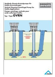
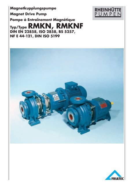
MagnetkupplungspumpeMagnet Drive PumpPompe à Entraînement Magnètique<strong>Typ</strong>/<strong>Typ</strong>e <strong>RMKN</strong>, <strong>RMKN</strong>FDIN EN 22858, ISO 2858, BS 5257,NF E 44-121, DIN ISO 5199
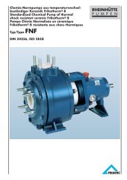
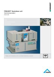
TeileverzeichnisParts ListDésignationsTeil-Nr.BenennungPart-No.DesignationRepèreDésignation102 Spiralgehäuse102.502 Spaltring102.902 Stiftschraube102.920 Mutter183 Stützfuß183.901 Sechskantschraube183.930 Sicherung211 Pumpenwelle211.940 Paßfeder213 Antriebswelle213.940.0 Paßfeder213.940.1 Paßfeder230 Laufrad321 Radialkugellager330 Lagerträger330.901 Sechskantschraube330.932 Sicherungsring330.950 Feder361 Endlagerdeckel361.421 Radial-Wellendichtung386 Axiallagerring485 Mitnehmerring506 Haltering506.914 Innen-Sechskantschraube509 Zwischenring509.400 Flachdichtung509.902 Stiftschraube509.920 Mutter511 Zentrierring511.400.0 Flachdichtung511.400.1 Flachdichtung511.400.2 Flachdichtung511.901 Sechskantschraube511.930 Sicherung520 Hülse529 Lagerhülse545 Lagerbuchse551 Abstandscheibe817 Spaltrohr817.723 Flansch818 Rotor847 Magnetkupplung921 Wellenmutter931 Sicherungsblech102 Volute casing102.502 Wear ring102.902 Stud102.920 Hexagon nut183 Support183.901 Hexagon screw183.930 Lock211 Pump shaft211.940 Key213 Top shaft213.940.0 Key213.940.1 Key230 Impeller321 Radial ball bearing330 Bearing bracket330.901 Hexagon screw330.932 Circlip330.950 Spring361 Bearing end cover361.421 Radial shaft sealing ring386 Thrust bearing ring485 Rotating ring506 Retaining ring506.914 Cyl. screw509 Intermediate ring509.400 Gasket509.902 Stud509.920 Hexagon nut511 Centering ring511.400.0 Gasket511.400.1 Gasket511.400.2 Gasket511.901 Hexagon screw511.930 Lock520 Sleeve529 Shaft sleeve bearing545 Bearing bushing551 Distance washer817 Spacer-can817.723 Flange818 Rotor847 Magnetic coupling921 Shaft nut931 Locking washer102 Volute102.502 Bague d’étanchéité102.902 Goujon102.920 Ecrou183 Béquille183.901 Vis six pans183.930 Frein211 Arbre de pompe211.940 Clavette213 Arbre de commande213.940.0 Clavette213.940.1 Clavette230 Turbine321 Roulement à billes330 Corps de palier330.901 Vis six pans330.932 Bague frein330.950 Ressort361 Couvercle arrière361.421 Bague d’étanchéité386 Douille de butée485 Anneau d’entraînement506 Bague d’arrêt506.914 Vis à six pans creux509 Bague intermédiaire509.400 Joint plat509.902 Goujon509.920 Ecrou511 Bague de centrage511.400.0 Joint plat511.400.1 Joint plat511.400.2 Joint plat511.901 Vis six pans511.930 Frein520 Chemise529 Chemise de palier545 Coussinet551 Rondelle entretoise817 Boîte entre-fer817.723 Bride818 Rotor847 Accouplement.magnétique921 Ecrou d’arbre931 Tôle freinTeil-Nr. und Benennung nachDIN 242505Part-No. and designation in accordancewith DIN 24250No. de pièces et désignation selonDIN 24250
<strong>RMKN</strong>F Flanschmotorausführung<strong>RMKN</strong>F Close-Coupled Design<strong>RMKN</strong>F Exécution monobloc avec moteur à brideDieser Pumpentyp ist eine kompakteVariante der konventionellen Magnetkupplungspumpe<strong>Typ</strong> <strong>RMKN</strong>.Die Flanschmotorvariante ist nur inden Größen des Lagerträgers I und IIlieferbar.Konstruktionsmerkmale● Ausrichten der Kupplung entfällt● Leichte Motor-Montage und Demontagedurch Führungsstifte● Wahlweise mit/ohne Stützfuß bzw.mit/ohne Grundplatte. Dadurch isteine kostengünstige, fundamentloseAufstellung möglich● Verwendung von Standardmotorenmöglich● Problemloses Umrüsten der konventionellenBauart in Flanschmotorausführung● Geringe ErsatzteilhaltungThis pump type is a compact variationof the conventional <strong>RMKN</strong> magneticdrive pump.The close-coupled design is availablefor bearing bracket sizes I and II only.Construction features● No coupling alignment required● Guide dowels make mounting and removalof motor easy● Choice of with/without support foot,alternatively with/without base plate.This makes cost-effective installationpossible without foundations● Use of standard motors possible● Conversion from conventional designto close-coupled design withoutproblems● Minimum spares holdingCe type de pompe est une variantecompacte de la pompe à entraînementmagnétique classique type <strong>RMKN</strong>.Seules les tailles de pompe sur chaisesde palier I et Il peuvent être livrées enexécution monobloc avec moteur àbride.Caractéristiques constructives● Pas d’alignement nécessaire● Montage et démontage aisés dumoteur grâce aux goupilles deguidage● Exécution avec ou sans béquille,c’est à dire montage avec ou sanstaille du socle.● Utilisation de moteurs standard● Modification aisée d’une pompestandard en exécution monobloc● Stockage réduit de pièces derechange6
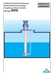
Einsatzgebiete / WerkstoffeRange of application / MaterialsDomaine d’utilisation / MatériauxEinsatzgebiete undAusführungsvarianten● Standardausführung für aggressive,giftige und explosible, auch leichtfeststoffbeladene, Fördermedien● Heizbare Ausführung (Spiralgehäuseund/oder Lagerträger). Bei <strong>RMKN</strong>Fnur Spiralgehäuse● Sonderausführung für flüssigenSchwefel, Pech, Teer u. a.● Sonderausführung mit Anschlüssenfür Fremdspülung● Sonderausführung mit Kühler fürFördermedien bis 350 °C● Flanschmotorausführung (<strong>RMKN</strong>F).Baugrößen● Nennweiten der Druckstutzen vonDN 32 bis DN 150.Anschlußmaße entsprechenDIN EN 22858.Range of application anddesign variations● Standard design for aggressive,toxic, explosive and slightly solidcontaining media● Heated design (volute casing and/orbearing bracket). For design <strong>RMKN</strong>Fonly volute casing● Special designs for liquid sulphur,pitch, tar etc● Special design with connections forexternal flushing● Special design with cooler for liquidsup to 350 °C● Close-coupled design (<strong>RMKN</strong>F).Sizes● Discharge flange sizes from DN 32up to DN 150.Dimensions according toDIN EN 22858.Domaine d’utilisationet variantes● Exécution standard pour liquidesagressifs, toxiques et explosifs, maiségalement faiblement chargés● Exécution avec enveloppe de réchauffage(sur volute et/ou chaise de palier).Pour exécution <strong>RMKN</strong>F seulementvolute● Exécution spéciale pour soufre liquide,brai, goudron, etc.● Exécution spéciale avec raccordementspour lubrification extérieure● Exécution spéciale avec refroidisseurpour liquide jusqu’à 350 °C● Exécution avec moteur à flasque-bride(<strong>RMKN</strong>F).Modèles● Diamètre de refoulement de DN 32jusqu’à DN 150.Dimensions siuvant normeDIN EN 22858.WerkstoffeMaterialsHydraulische Teile / Hydraulic parts / Pièces hydrauliquesMatériauxWerkstoff-Kurzbezeichnung Werkstoff-Nr. HandelsnameMaterial designation Material No. TradenameDésignation matériau No. matériau Nom commercialDIN 17006 / EN 10027GGG - 40.3 0.7043GS - C 25 1.0619G - X 6 CrNiMo 18 10 1.4408G - X 5 CrMo 29 21.4136 SG - X 5 CrNiMoCu 28 5 – HA 28 5G - X 3 NiCrMoCu 25 20 6 (1.4529) RH 25 7G - X 2 CrNi 22 111.4306 SG - X 3 NiCrMoCu 30 20 – R 30 20G - X 2 CrNiSi 18 15 4 1.4361 R 4 SiG - NiMo 17 Cr (2.4686) R 70 C 1, Alloy CG - NiMo 28 (2.4685) R 70 B 1, Alloy BG - Ti 2 3.7031 Titanlegierung / Titanium alloy /Alliage de titaneSpalttopf: Hastelloy C 4, 1.4361,Titanlegierung u. a.Gleitlager: Rein-Siliziumkarbid(siliziumfrei)Lagerträger: Sphäroguß GGG 40.3,heizbare Ausführung 1.4552Flachdichtungen: asbestfrei7Spacer-can: Hastelloy C 4, 1.4361,Titanium alloy and othersSleeve bearing assembly: High puritysilicon carbide (silicon-free)Bearing bracket: Nodular ironGGG 40.3, heated design in steel 1.4552Gaskets: asbestos-freeBoîte entre-fer: Hastelloy C 4, 1.4361,alliage de titane, etc.Palier lisse: Carbure de silicium pursans silicium résiduelCorps de palier: Fonte sphéroïdaleGGG 40.3, ou acier (1.4552) pourl’exécution avec réchauffageJoints plats: sans amiante
Überwachungs- und SchutzgeräteSafety Check and Protection FacilitiesSystèmes de surveillance et de protectionSekundärabdichtungSecondary sealingEtanchéité secondaire101101080705020309048
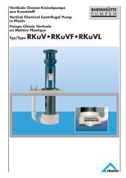
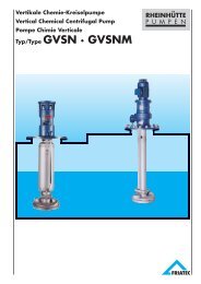
Geräte zur Pumpenüberwachung01 Schwingungsmessung amkupplungsseitigen Wälzlager02 Temperaturüberwachung amSpalttopf03 Temperaturüberwachung imFördermedium04 Leckageüberwachung05 Druckkontrolle am DruckstutzenSchutzgeräte06 Trockenlaufschutz durch Wirkleistungsmessung07 Trockenlaufschutz durch Durchflußwächter08 Trockenlaufschutz durch Niveauüberwachungmit Schwimmer09 Trockenlaufschutz durch Niveauüberwachungmit Fühler (vorzugsweisesenkrechter Einbau)10 Zusätzlicher Schutz durch Sekundärabdichtung(fettgefüllter Raum).11 Notfallabdichtung für Medien einersehr hohen Gefahrenklasse, bestehendaus Druckgasgenerator, Sperrmittelbehälterfür mediumresistentePTFE-Fettmischung und einem Sensorzur Überwachung des Gehäuseraumes.Im Havariefall wird die Fettmischungin Sekundenbruchteil unterhohem Druck in den Lagerbereicheingeschossen.Monitoring facilities01 Vibration measurement at couplingend antifriction bearing02 Temperature monitoring of thespacer-can03 Temperature monitoring of thepumped liquid04 Leakage detection05 Pressure control at the dischargeflangeProtection facilities06 Protection against dry running byload measurement07 Protection against dry running byflow detection08 Protection against dry running bylevel check with float09 Protection against dry running bylevel check with sensing element(vertical installation prefered)10 Additional protection provided bysecondary sealing arrangement(grease filled barrier).11 Emergency sealing for extremelyhazardous media, consisting of a gaspressure generator, sealant containerfor media-resistant PTFE type grease,and a sensor to monitor the casingarea. In the event of failure, the greasemixture is injected into the bearing areaunder high pressure within a fraction ofa second.06Systèmes de surveillance01 Mesure de vibration au niveau duroulement côte accouplement02 Surveillance de la température auniveau de la boîte entre-fer03 Surveillance de la température duliquide véhiculé04 Surveillance des fuites05 Contrôle de la pression au refoulementSystèmes de protection06 Protection contre le fonctionnementà sec par un détecteur de charge07 Protection contre le fonctionnementà sec par un contrôleur de débit08 Protection contre la fonctionnementà sec par surveillance du niveau avecflotteur09 Protection contre le fonctionnementà sec par surveillance du niveau avecune sonde (un montage vertical estsouhaité)10 Protection supplémentaire parétanchéité secondaire (espace remplide graisse).11 Etanchéité de sécurité pour lesproduits présentant un très fortdanger, se composant d’un générateurde gaz comprimé, d’un réservoirde barrage avec graisse PTFE etd’un capteur pour surveiller l’espacedu palier. En cas d’incidents, en unefraction de seconde, la graisse estinjectée sous forte pression dansl’espace du palier.9
EinbaumaßeDimensionsEncombrementaflyh1DNsh2tDN Dy= Ausbaumaßy= Spacer lengthsy= Cote de dégagements1wuWellenende nach DIN 748Shaft end to DIN 748Bout d’arbre selon DIN 748n1n2m 1m 2n3Paßfeder nach DIN 6885/1Key to DIN 6885/1Clavette selon DIN 6885/1s 2dbGröße Lagerträger Flansche*) Pumpenmaße Fußmaße WellenendeSize Bearing Flanges*) Pump Sizes Support Dimensions Shaft EndModèle Bracket Brides*) Cotes de pompe Cotes de Fixation Bout d’arbresCorps de pal. DN D DN S a f h 1 h 2 b m 1 m 2 n 1 n 2 n 3 s 1 s 2 w y d l t u32-125 112 140 190 14032-160 I80 385 132 160 50 100 70285 24 50 26,9 832 50240 190 110 14 14 10032-200 160 18032-250 II 100 500 180 225 65 125 95 320 250 370 32 80 35,3 1040-125 112 140 210 1608040-160 I385 132 160 50 100 70 240 190 285 24 50 26,9 840-200 40 65160 180 265 212 110 14 14 10010040-250180 225II 50065 125 95 320 250 370 32 80 35,3 1040-315 125 200 250 345 28050-125 132 160 240 19050-160 I 100 385160 180 50 100 70 285 24 50 26,9 8265 21250-200 50 80 200 110 14 14 10050-250180 225II 125 50065 125 95 320 250 370 32 80 35,3 1050-315 225 280 345 28065-125 I 385160 180 285 24 50 26,9 8280 21210065-160 100 200 65 125 95 1465-200 II 65 100 500 180 225 320 250 110 14 370 32 80 35,3 1065-250200 25012580 160 120 360 280 1401865-315 Ill 530 225 280 400 315 42 110 45,1 1280-160 225 320 250180 65 125 95 1480-200 II 500 250 345 280 32 80 35,3 1080-250 80 125 125 225 280110 14 370 140400 31580-315250 315 80 160 120 18Ill 53042 110 45,1 1280-400 280 355 435 355100-200 II 125 500 200 360 280 32 80 35,3 10280100-250 100 125 225 80 160 120 370 140Ill 140 530400 315 110 18 14 42 110 45,1 12100-315250 315125-250250 80 160 120 400 315 18Ill 125 150 140 530 355 110 14 370 140 42 110 45,1 12125-315 280 100 200 150 500 400 22150-250 Ill 150 200 160 530 280 375 100 200 150 500 400 110 23 14 370 180 42 110 45,1 12*) nach DIN 2533, DIN 2543 *) to DIN 2533, DIN 2543 *) selon DIN 2533, DIN 254310
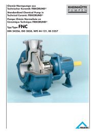
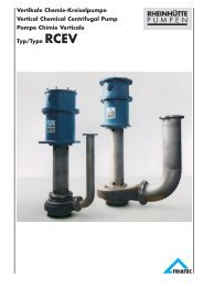
LeistungsübersichtRange chartPlage d‘utilisationFörderstrom Q / Quantity Q / Débit Q (US.GPM/IMP.GPM)Förderhöhe / Differential Head / Hauteur manométrique H(m)40/31532/25032/20032/16032/12580/40050/31540/250 50/25050/20040/20065/315 80/315100/315125/31565/250 80/250100/25080/20065/20040/160 50/160 65/16080/16050/125 65/12540/125100/200125/250150/25050 Hz n = 1450Förderhöhe / Differential Head / Hauteur manométrique H(m)Förderstrom Q / Quantity Q / Débit Q (m3 / h)50/315Förderhöhe / Differential Head / Hauteur manométrique H(m)32/25033/20032/16032/12540/25040/20040/16040/12550/25050/20050/16050/12565/25080/25065/20080/20065/16080/16065/125100/250100/20050 Hz n = 2900Förderhöhe / Differential Head / Hauteur manométrique H(m)11Förderstrom Q / Quantity Q / Débit Q (m3/ h)
Magnetkupplungspumpe <strong>Typ</strong> <strong>RMKN</strong>mit Airbag®-Notfallabdichtung für gefährlicheFördermedien.Magnetic drive pump type <strong>RMKN</strong>with emergency sealing (Airbag®) forhazardous media.Pompe à entraînement magnétiquetype <strong>RMKN</strong> équipée d’une étanchéitéde sécurité (Airbag®)pour produitsdangereux.Magnetkupplungspumpe <strong>Typ</strong> <strong>RMKN</strong>in heizbarer Ausführung zur Förderungvon flüssigem Pech bei 220 °C.Magnetic drive pump type <strong>RMKN</strong>in heated design for handling liquid pitchat 220 °C.Pompe à entraînement magnétique type<strong>RMKN</strong> avec enveloppe de réchauffagepour le pompage de brai liquide à 220 °C.3.47.0001-1002 d-e-fFRIATEC-Rheinhütte GmbH & Co.Postfach / P.O.B. 12 05 45 • D-65083 WiesbadenRheingaustr. 96 -100 • D-65203 WiesbadenTel. +49 (0)611/604-0 • Fax +49 (0)611/604-328Internet: www.friatec.de • www.rheinhuette.dee-mail: info@rheinhuette.de • service@rheinhuette.de05 · 10.02 WST