19.0 limitatore di coppia torque limiter rutschkupplung limiteur de ...
19.0 limitatore di coppia torque limiter rutschkupplung limiteur de ...
19.0 limitatore di coppia torque limiter rutschkupplung limiteur de ...

You also want an ePaper? Increase the reach of your titles
YUMPU automatically turns print PDFs into web optimized ePapers that Google loves.
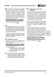
19.3 Dimensioni19.3 Dimensions 19.3 Abmessungen 19.3 DimensionsTipoTypeTypTypeC Q Q 1 G h B 2 B H7 B 1H7 t 1 b LVF 44L 79 32 32 M20 40 18 11 20.8 6 12VF 49L 105 51 41 M30 63 25 14 28.3 8 15VF 63L 137 61 60 M30 63 25 14 28.3 8 15VF 72L 143 60 60 M35 71 28 20 31.3 8 20VF 86L 165 86 70 M40 80 35 25 38.3 10 25Se non preventivamente specificato, i riduttori verranno forniti con laghiera a sinistra guardando il motore elettrico in posizione <strong>di</strong> montaggioB3.Unless otherwise specifiedVFL gear units are suppliedwith ring nuton the left handsi<strong>de</strong>, viewing from electric motor andgearbox in theB3 mounting position.Wenn nicht an<strong>de</strong>rs angegeben, wer<strong>de</strong>n <strong>di</strong>e Getriebe geliefert mit <strong>de</strong>rVerstellmutter links, mit Sicht auf <strong>de</strong>n E-Motor.En standard et en l’absence d’information précise, les réducteurs serontlivrés avec le système <strong>de</strong> décrabotage à gauche, vue se plaçantdu cöté du moteurr électrique.19.4 Lubrificazione19.4 Lubrication 19.4 Schmierung 19.4 LubricationNei riduttori con <strong>limitatore</strong> <strong>di</strong> <strong>coppia</strong>incorporato viene adottata lalubrificazione permanente conolio sintetico, questo permetteI’installazione in tutte le posizioni<strong>di</strong> montaggio.II giusto riempimento viene eseguitoall’atto <strong>de</strong>l montaggio. Nellatabella (V32) vengono in<strong>di</strong>cate lequantità <strong>di</strong> lubrificante contenutenei riduttori serie VFL. Dopo lunghee severe prove effettuatepresso la ns. Sala Esperienze abbiamoverificato che la lubrificazionea grasso <strong>de</strong>i gruppi con<strong>limitatore</strong> <strong>di</strong> <strong>coppia</strong> non è consigliata.I migliori risultati e prestazionisi ottengono utilizzando oliosintetico:SHELL: TIVELA SD 460Questo lubrificante può essereimpiegato per temperatura ambienteda -15 °C a +50°C.Gear units featuring the<strong>torque</strong>-<strong>limiter</strong> <strong>de</strong>vice are factorylubed"for life" with polyglycol-basesynthetic oil.Units are factory filledwith the appropriatequantity of oil, allowinginstallation in any mounting position.See table (V32) for reference.Notice: Thorough testing conductedby the R & D Dept.<strong>de</strong>monstrates that lubrication requirementsof the <strong>torque</strong> <strong>limiter</strong> <strong>de</strong>viceare not fulfilledby grease.Best results are achievedby thesynthetic-base oil:SHELL - TIVELA SD 460Above lubricant allows operationwithin an ambient temperaturerange of -15°C — +50°C.In Schneckengetrieben mit Rutschkupplungerfolgt eine Dauerschmierungmit synthetischem Öl.Alle Einbaulagen sindmöglich.Die Füllung mit <strong>de</strong>r richtigenMenge erfolgt während<strong>de</strong>r Montage.Die folgen<strong>de</strong> Tabelle (V32)stelIt <strong>di</strong>e erfor<strong>de</strong>rlichen Schmiermittelmengen,<strong>de</strong>r Serie VFL,dar. Langere und gründliche Untersuchungenunserer Entwicklungsabteilunghaben ergeben,dass eine Fettschmierung <strong>de</strong>rGetriebe mit Rutschkupplungnicht ratsam ist. Die besten Ergebnissewur<strong>de</strong>n von uns mit<strong>de</strong>m synthetischen Öl:SHELL: TIVELA SD 460 erzielt.Dieses Schmiermittel kann beiUmgebungstemperaturen von-15 °C bis + 50° C verwen<strong>de</strong>twer<strong>de</strong>n.Dans les réducteurs à <strong>limiteur</strong> <strong>de</strong>couple incorporé, la lubrification àvie à I’huile synthétique à étéadoptée. Ceci permet I’insta lationdu groupe dans toutes lespositions <strong>de</strong> montage. Le remplissageavec la bonne quantité<strong>de</strong> huile est effectué au momentdu montage du réducteur. Dansle tableau (V32) sont in<strong>di</strong>queésles quantités <strong>de</strong> lubrifiant prévuesdans le réducteur VFL. Après <strong>de</strong>longs et sévères essais effectuésauprès <strong>de</strong> notre département rechercheet développement nousavons vérifié que la lubrification àla graisse <strong>de</strong>s groupes avec <strong>limiteur</strong><strong>de</strong> couple n’est pas la plusadaptée. Les meilleurs résultatset prestations s’obtiennent en utilisantune huile synthétiqueSHELL: TIVELA SD 460. Ce lubrifiantpeut etre employé pour<strong>de</strong>s températures ambiantes <strong>de</strong>-15 °C a + 50°C.(V32)Lubrificazione a olio (litri)Oil lubrication (litres)Öl-Schmierung (liter)Lubrification à l’huile (litres)Tipo / Type / Typ / TypeVF 44L VF 49L VF 63L VF 72L VF 86L0.075 0.12 0.32 0.50 1.20174 B
19.5 Registrazione <strong>coppia</strong><strong>di</strong> slittamentoIn fabbrica viene eseguita unapretaratura <strong>de</strong>llo slittamento su unmomento torcente coinci<strong>de</strong>nte colvalore <strong>di</strong> <strong>coppia</strong> nominale M n2 [n 1 =1400] <strong>de</strong>l riduttore tipo VFL.Qui <strong>di</strong> seguito sono <strong>de</strong>scritte leoperazioni eseguite in fabbrica perrealizzare la taratura <strong>de</strong>lla <strong>coppia</strong><strong>di</strong> slittamento. Le stesse operazioni,a meno <strong>de</strong>l passo (2), dovrannoessere ripercorse quando sivuole impostare un valore <strong>di</strong> <strong>coppia</strong><strong>di</strong>verso dall'originale.19.5 Slip <strong>torque</strong> setting 19.5 RutschmomenteinstellungA preliminary slip <strong>torque</strong> setting isconducted at the factory. Referenceis ma<strong>de</strong> to <strong>torque</strong> rating M n2[n 1 = 1400] of the captionedVFLgear unit.Here below the operations performedatthe factor for the initialadjustment are listed.Same steps, with the exceptionof phase (2), must be followedwhen a <strong>di</strong>fferent <strong>torque</strong> setting isrequired.Eine Voreinstellung <strong>de</strong>s Rutschmomentswir<strong>di</strong>m werk durchgeführt.Das voreingestellte Moment entspricht<strong>de</strong>m im Katalog angegebenenNennmoment M n2 [n 1 = 1400]<strong>de</strong>s Getriebes Typ VFL.Nachfolgend wer<strong>de</strong>n <strong>di</strong>e im Werkdurchgeführten Operationen zur Einstellung<strong>de</strong>s Rutschmoments beschrieben.Die gleichen Schritte, mitAusnahme <strong>de</strong>s Schrittes Nr. 2, müssenwie<strong>de</strong>rholt wer<strong>de</strong>n, wenn einan<strong>de</strong>rer Momentwert benötigt wird.19.5 Réglage du couple <strong>de</strong>glissementUn pré-tarage du couple <strong>de</strong> glissementsur la base d'un moment <strong>de</strong>torsion coincidant avec la valeur ducouple nominal M n2 [n 1 = 1400] duréducteur type VFL est effectuéen usineCi-après sont décrites les operations effectuées en usine pourréaliser le tarage du couple <strong>de</strong>glissement. Les mêmes opérations,sauf l'étape 2, <strong>de</strong>vrontêtre effectuées si l'on veut obtenirun couple <strong>di</strong>fférent <strong>de</strong> celuiprévu à l'origine.1 La ghiera <strong>di</strong> registrazione vieneavvitata fino a che le molle atazza non sono sufficientementecaricate da non potere ruotare liberamente,se azionate manualmente.2 Per mezzo <strong>di</strong> un bulino vengonoincise, in i<strong>de</strong>ntica posizioneangolare, due marcature <strong>di</strong> riferimento,sia sulla ghiera chesulla sporgenza d'albero lento.Questa posizione <strong>di</strong> riferimentocostituirà il punto iniziale per ilconteggio <strong>de</strong>i successivi giri<strong>de</strong>lla ghiera e la conseguentetaratura <strong>di</strong> <strong>coppia</strong>.3 Infine la ghiera viene avvitata<strong>de</strong>lle frazioni <strong>di</strong> giro corrispon<strong>de</strong>ntial valore <strong>di</strong> <strong>coppia</strong> nominaleM n2 <strong>de</strong>l riduttore inoggetto. Il riferimento in questocaso è il <strong>di</strong>agramma sotto riportato,il quale sarà d'utilitàanche per le eventuali nuoveimpostazioni che si dovesseroren<strong>de</strong>re necessarie nel tempo.1 Ring nut is tighteneduntilspring washers are sufficientlyloa<strong>de</strong>d that manual rotation ishardly possible.2 By means of an engravermarks are ma<strong>de</strong>, in i<strong>de</strong>ntical(angular) position, on both thering nut andthe hollow shaft.Setting will then be referredtoas the zero-point for the consequentslip <strong>torque</strong> adjustment,through turning of the ring nut.3 Ring nut is then turnedof thenumber of turns, or fraction of,correspon<strong>di</strong>ng to nominal <strong>torque</strong>rating M n2 of the captionedgearunit. In this case the <strong>di</strong>agramshown here un<strong>de</strong>r refers as tothe proportion between numberof turns andtransmissible<strong>torque</strong>. Same <strong>di</strong>agram comeshandy for customised <strong>torque</strong> adjustments,shouldthese be requiredwithtime.1 Die Verstellmutter so weit anziehen,daß sich <strong>di</strong>e Tellerfe<strong>de</strong>rnnicht mehr von Handdrehen lassen.2 Es wer<strong>de</strong>n 2 Bezugsmarkierungenunter <strong>de</strong>m gleichen Winkel sowohlauf <strong>de</strong>r Verstellmutter als auch auf<strong>de</strong>r Hohlwelle angebracht. Diehiermit gekennzeichnete Stellungist <strong>de</strong>r Ausgangspunkt für je<strong>de</strong>weitere Rutschmomenteinstellungdurch <strong>di</strong>e Verdrehung <strong>de</strong>r Verstellmutter.3 Die Verstellmutter wirdsoweitangezogen, bis das gewünschteNennmoment M n2 <strong>de</strong>s Getriebeserreicht ist. Sollte ein an<strong>de</strong>resRutschmoment erfor<strong>de</strong>rlich sein,ist gemäß folgen<strong>de</strong>m Diagramm(ausgehendvon Punkt 2.) <strong>di</strong>eVerstellmutter um <strong>de</strong>n angegbenenWert gegenüber <strong>de</strong>r Hohlwellezu drehen (¼ bis 2Umdrehungen).1 L'écrou <strong>de</strong> réglage est visséjusqu'à ce que les ron<strong>de</strong>llesélastiques soient suffisammentprécontraintes et ne puissentplus tourner librment par uneaction manuelle.2 Au moyen d'un marqueur on réalise<strong>de</strong>ux repères dans la mêmeposition angulaire, l'un surl'écrou et l'autre sur la saillie <strong>de</strong>l'arbre lent. Cette position <strong>de</strong>référence constituera le point<strong>de</strong> départ pour le décompte<strong>de</strong>s tours successifs <strong>de</strong> labague et en conséquence letarage du couple.3 En final, la bague est vissée <strong>de</strong>sfractions <strong>de</strong> tours correspondantà la valeur du couple nominalM n2 du réducteur concerné.La référence dans ce cas est le<strong>di</strong>agramme ci-<strong>de</strong>ssous, lequelservira également pour les éventuelsréglages qui s'avéreraientnécessaires dans le temps.(V33)B 175
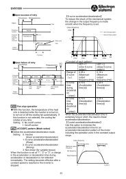
Rivelatore dl albero fermoSu richiesta è <strong>di</strong>sponibile un rivelatoreelettronico il quale segnalail fermo <strong>de</strong>ll’albero lento.II rivelatore <strong>di</strong> albero fermo ècomposto da due elementi principali:il sensore <strong>di</strong> prossimità e lacentralina elettronica completa <strong>di</strong>zoccolo <strong>di</strong> collegamento montabilesul pannello <strong>di</strong> controllo.II periodo <strong>di</strong> tempo che intercorretra il riconoscimento <strong>di</strong> fermo alberoe I’arresto <strong>de</strong>lla macchinapuò essere tarato, me<strong>di</strong>ante registrazione<strong>de</strong>l pomello posto sullacentralina.Questi tempi sono compresi tra 2e 15 secon<strong>di</strong>.Standstill shaft <strong>de</strong>tectorAn electronic <strong>de</strong>tector advisingthat the output shaft is at standstillis available upon request.The sensor is ma<strong>de</strong> of two mainelements: a proximity sensor andan electronic cardwith mountingbase to be fittedon main checkpanel.The <strong>de</strong>lay (from 2 to 15 sec) between<strong>de</strong>tecting of the standstillshaft andthe machine stoppingcan be adjusted by means ofknob placedon the card.StillstandsuberwachungEin elektronischer Stillstandsanzeigerfür <strong>di</strong>e Ausgangswellekann mitgelieferte wer<strong>de</strong>n.Der Sensor besteht aus zwei Elementen,<strong>de</strong>m Näherungssensorund<strong>de</strong>m elektronischen Steuergehäuse,welches geeignet ist für<strong>de</strong>n Einbau in eine Schalttafel.Die Zeit zwischen <strong>de</strong>r Wellestillstan<strong>de</strong>rserkennungund <strong>de</strong>m Stoppen<strong>de</strong>r Arbeitsma chine kanndurch einen Knopf am Steuergehäuseverstellt wer<strong>de</strong>n.Diese Zeiten betragen 2 bis 15Sekun<strong>de</strong>n.Detecteur d’arbre a l’arretUn détecteur électronique, signalantque I’arbre lent est arrêté,peut être fourni sur <strong>de</strong>man<strong>de</strong>.Ce <strong>de</strong>tecteur est composé <strong>de</strong> 2éléments principaux: le capteur<strong>de</strong> proximité et la carte électroniqueavec son support <strong>de</strong> liaisonadaptable sur un panneau <strong>de</strong>contrôle.Le pério<strong>de</strong> qui s’écoule entre lemoment où le capteur signale leblocage <strong>de</strong> I’arbre <strong>de</strong> sortie etI’arrêt <strong>de</strong> la machine peut être régléa I’ai<strong>de</strong> d’un bauton installésur la carte.Cette pério<strong>de</strong> peut varier entre 2et 15 secon<strong>de</strong>s.(V34)176 B
INFORMAZIONI GENERALIGENERAL INFORMATIONALLGEMEINE INFORMATIONENINFORMATIONS GENERALESRIDUTTORI A VITE SENZA FINE SERIE VF-VFR-VF/VFWORM GEARBOXES SERIES VF-VFR-VF/VFSCHNECKENGETRIEBE SERIE VF-VFR-VF/VFREDUCTEURS A VIS SANS FIN SERIE VF-VFR-VF/VFMOTORI ELETTRICIELECTRIC MOTORSELEKTROMOTORENMOTEURS ELECTRIQUESAParagrafoHea<strong>di</strong>ngPaginaPageDescrizione Description Beschreibung Description1.0 Introduzione Introduction Einführung Introduction 22.0 Simbologia e unità <strong>di</strong> misura Symbols and units of measure Verwen<strong>de</strong>te Symbole und Begriffe Symboles et unités <strong>de</strong> mesure 43.0 Coppia in uscita Output <strong>torque</strong> Abtriebsdrehmoment Couple en sortie 54.0 Potenza Power Leistung Puissance 65.0 Potenza termica Thermal capacity Thermische Grenzleistung Puissance thermique 66.0 Ren<strong>di</strong>mento Efficiency Wirkungsgrad Ren<strong>de</strong>ment 77.0 Rapporto <strong>di</strong> riduzione Gear ratio Übersetzung Rapport <strong>de</strong> réduction 78.0 Velocità angolare Angular speedDrehzahl Vitesse angulaire 79.0 Momento d’inerzia Moment of inertia Trägheitsmoment Moment d’inertie 810.0 Fattore <strong>di</strong> servizio Service factor Betriebsfaktor Facteur <strong>de</strong> service 811.0 Lubrificazione Lubrication Schmierung Lubrification 912.0 Manutenzione Maintenance Wartung Entretien 913.0 Scelta Selection Auswahl Sélection 1014.0 Verifiche Verification Prüfungen Vérifications 1315.0 Installazione Installation Installation Installation 1416.0 Stoccaggio Storage Lagerung Stockage 1517.0 Con<strong>di</strong>zioni <strong>di</strong> fornitura Con<strong>di</strong>tions of supply Lieferbe<strong>di</strong>ngungen Con<strong>di</strong>tions <strong>de</strong> livraison 1618.0 Specifiche <strong>de</strong>lla vernice Paint specifications Eigenschaften <strong>de</strong>r Antrichstoffe Spécifications <strong>de</strong> la peinture 16B1.0 Caratteristiche costruttive Design characteristics Konstruktive Eigenschaften Caractéristiques <strong>de</strong> construction 182.0 Forme costruttive Versions Bauformen Formes <strong>de</strong> construction 193.0 Esecuzioni <strong>di</strong> montaggio Arrangements Bauform Execution <strong>de</strong> montage 204.0 Designazione Designation Bezeichnung Désignation 225.0 Informazioni generali General information Allgemeine informationen Informations generales 266.0 Lubrificazione Lubrication Schmierung Lubrification 307.0 Carichi ra<strong>di</strong>ali Ra<strong>di</strong>al loads Ra<strong>di</strong>alkräfte Charges ra<strong>di</strong>ales 388.0 Carichi assiali Thrust loads Axialkräfte Charges axiales 409.0 Rotazione alberi Shaft arrangement Wellendrehung Rotation arbres 4110.0 Tabelle dati tecnici motoriduttori(motori a polarità singola)11.0 Tabelle dati tecnici motoriduttori(motori a doppia polarità)Gearmotor selection charts (singlespeedmotors)Gearmotor selection charts (doublespeedmotors)Getriebemotorenauswahltabellen(eintourige Motoren)Getriebemotorenauswahltabellen(polumschaltbare)Tableaux <strong>de</strong>s caractéristiquestechniques motoréducteurs (moteursà simple polarité) 43Tableaux <strong>de</strong>s caractéristiquestechniques motoréducteurs (Moteursdouble polartté) 7512.0 Tabelle dati tecnici riduttori Speed reducer selection charts Getriebeauswahltabellen Tableaux <strong>de</strong>s caractéristiquestechniques réducteurs 10113.0 Pre<strong>di</strong>sposizioni possibili Motor availability Anbaumöglichkeiten Pré<strong>di</strong>spositions possibles 11714.0 Momento d’inerzia Moment of inertia Trägheitsmoment Moment d’inertie 11915.0 Dimensioni riduttori IEC IEC gearbox <strong>di</strong>mensions IEC-getriebe abmessungen Dimensions reducteurs pre<strong>di</strong>sposespour moteurs normalises IEC 12916.0 Dimensioni riduttori Speed reducer <strong>di</strong>mensions Getriebe abmessungen Dimensions reducteurs 16517.0 Opzioni RB, RBO RB, RBO Options Optionen RB, RBO Options RB, RBO 16918.0 Accessori Accessories Zubehör Accessoires 170<strong>19.0</strong> Limitatore <strong>di</strong> <strong>coppia</strong> Torque <strong>limiter</strong> Rutschkupplung Limiteur <strong>de</strong> couple 171C1.0 Caratteristiche generali General characteristics Allgemeine Eigenschaften Caractéristiques générales 1782.0 Forme costruttive Versions Bauformen Formes <strong>de</strong>e construction 1793.0 Designazione motore Motor <strong>de</strong>signation Motor bezeichnung Moteur désignation 1804.0 Simbologia e unità <strong>di</strong> misura Symbols and units of measure Verwen<strong>de</strong>te Symbole und Einheiten Symboles et unités <strong>de</strong> mesure 1825.0 Caratteristiche meccaniche Mechanical characteristics Mechanische Eigenschaften Caractéristiques mécaniques 1836.0 Caratteristiche elettriche Electrical characteristics Elektrische Eigenschaften Caractéristiques électriques 1857.0 Motori asincroni autofrenanti Asynchronous brake motors Bremsmotoren Moteurs asynchrones freins 1898.0 Esecuzioni speciali Special execution Son<strong>de</strong>rausführungen Exécutions spéciales 1949.0 Tabelle dati tecnici motori IEC IEC motor selection charts IEC-Motoren auswahl Tabellen Tableaux caractéristiques techniques<strong>de</strong>s moteurs CEI 19710.0 Dimensioni Dimensions Abmessungen Dimensions 20111.0 Lista parti <strong>di</strong> ricabio Spare parts list Ersatzteilliste Liste <strong>de</strong>s pieces <strong>de</strong>tachee 205C 177
1.0 CARATTERISTICHEGENERALI1.0 GENERALCHARACTERISTICS1.0 ALLGEMEINEEIGENSCHAFTEN1.0 CARACTERISTIQUESGENERALES1.1 Programma <strong>di</strong>produzioneI motori elettrici asincroni trifase<strong>de</strong>l programma <strong>di</strong> produzione<strong>de</strong>lla BONFIGLIOLI RIDUTTORIsono previsti nelle formecostruttive base IMB5, IMB14 eloro <strong>de</strong>rivate con le seguentipolarità: 2, 4, 6, 2/4, 2/6, 2/8, 2/12.1.1 Production range1.1 Produktprogramm1.1 Programme <strong>de</strong>productionLes moteurs électriques asynchronestriphasés du programme<strong>de</strong> production <strong>de</strong> BONFIGLIOLIRIDUTTORI sont prévus dans lesformes <strong>de</strong> construction <strong>de</strong> baseIMB5, IMB14 et leur dérivés avecles polarités suivantes: 2, 4, 6,2/4, 2/6, 2/8, 2/12.The asynchronous three-phaseelectric motors of BONFIGLIOLIRIDUTTORI’s production, areavailable in basic <strong>de</strong>signs IMB5andIMB14 and<strong>de</strong>rived versions,with the following polarities:2, 4, 6, 2/4, 2/6, 2/8, 2/12.Die Dreiphasen-Asynchronmotorenaus <strong>de</strong>m Produktprogramm vonBONFIGLIOLI RIDUTTORI gibt esin <strong>de</strong>n Grundbauformen IMB5,IMB14 und<strong>de</strong>ren Ableitungen mitfolgen<strong>de</strong>n Polzahlen: 2, 4, 6, 2/4,2/6, 2/8 und2/12.1.2 NormativeI motori <strong>de</strong>scritti in questo catalogosono costruiti in accordo alleNorme edunificazioni applicabilievi<strong>de</strong>nziate nella tabella (C1).1.2 StandardsThe motors <strong>de</strong>scribed in this catalogueare manufacturedto theapplicable standards shown in table(C1).1.2 NormenDie in <strong>di</strong>esem Katalog beschriebenenMotoren sin<strong>di</strong>n Übereinstimmungmit <strong>de</strong>n in <strong>de</strong>r Tabelle(C1) angegebenen einschlägigenNormen undVereinheitlichungsrichtlinienkonstruiert wor<strong>de</strong>n.1.2 RéglementationsLes moteurs décrits dans ce cataloguesont construits en accordavec les Normes et standar<strong>di</strong>sationsapplicables mises en évi<strong>de</strong>ncedans le tableau (C1).(C1)Titolo / Title / Titel / Titre CEI / UNEL IECPrescrizioni generali per macchine elettroniche rotantiGeneral requirements for rotating electrical machinesAllgemeine Vorschriften für umlaufen<strong>de</strong> elektrische MaschinenPrescriptions générales pour machines électriques tournantesMarcatura <strong>de</strong>i terminali e senso <strong>di</strong> rotazione per macchine elettriche rotantiTerminal markings and<strong>di</strong>rection of rotation of rotating machinesKennzeichnung <strong>de</strong>r Anschlußklemmen und Drehrichtung von umlaufen<strong>de</strong>n elektrischen MaschinenDéfinitions <strong>de</strong>s bornes et sens <strong>de</strong> rotation pour machines électriques tournantesMeto<strong>di</strong> <strong>di</strong> raffreddamento <strong>de</strong>lle macchine elettricheMethods of cooling for electrical machinesVerfahren zur Kühlung von elektrischen MaschinenMétho<strong>de</strong>s <strong>de</strong> refroi<strong>di</strong>ssement <strong>de</strong>s machines électriquesDimensioni e potenze nominali per macchine elettriche rotantiDimensions andoutput ratings for rotating electrical machinesAuslegung <strong>de</strong>r Nennleistung von umlaufen<strong>de</strong>n elektrischen MaschinenDimensions, puissances nominales pour machines électriques tournantesClassificazione <strong>de</strong>i gra<strong>di</strong> <strong>di</strong> protezione <strong>de</strong>lle macchine elettriche rotantiClassification of <strong>de</strong>gree of protection provi<strong>de</strong>d by enclosures for rotating machinesKlassifizierung <strong>de</strong>r Schutzart von umlaufen<strong>de</strong>n elektrischen MaschinenClassification <strong>de</strong>s <strong>de</strong>grés <strong>de</strong> protection <strong>de</strong>s machines électriques tournantesLimiti <strong>di</strong> rumorositàNoise limitsGeräuschgrenzwerteLimites <strong>de</strong> bruitSigle <strong>di</strong> <strong>de</strong>signazione <strong>de</strong>lle forme costruttive e <strong>de</strong>i tipi <strong>di</strong> installazioneClassification of type of construction andmounting arrangementsAbkürzungen zur Kennzeichnung <strong>de</strong>r Bauform und <strong>de</strong>r EinbaulagenSigles <strong>de</strong> dénomination <strong>de</strong>s formes <strong>de</strong> construction et <strong>de</strong>s types d’installationTensione nominale per i sistemi <strong>di</strong> <strong>di</strong>stribuzione pubblica <strong>de</strong>ll’energia elettrica a bassa tensioneIEC standard voltageNennspannung für öffentliche NS-StromverteilungssystemeTension nominale pour les systèmes <strong>de</strong> <strong>di</strong>stribution publique <strong>de</strong> l’énergie électrique en basse tensionGrado <strong>di</strong> vibrazione <strong>de</strong>lle macchine elettricheVibration level of electric machines.Schwingstärke bei elektrischen MaschinenDegré <strong>de</strong> vibration <strong>de</strong>s machines électriquesCEI EN 60034-1 IEC 60034-1CEI2-8IEC60034-8CEI EN 60034-6 IEC 60034-6UNEL13113 - 7113117 - 7113118 - 71IEC 60072CEI EN 60034-5 IEC 60034-5CEI EN 60034-9 IEC 60034-9CEI EN 60034-7 IEC 60034-7CEI8-6IEC60038CEI EN 60034-14 IEC 60034-14EMCI motori sono in accordo alle Norme:BN/MeBN/M_FA• EN 50081-1, EN 050082-2BN / M_FD• EN 50081-2, EN 050082-2Se è richiesta la conformità alla NormaEN 50081-1, i motori con freno FD<strong>de</strong>vono essere provvisti <strong>di</strong> opportunofiltro capacitivo in ingresso al raddrizzatore.Tutti i nostri motori sono contrassegnaticon il marchio CE.EMCMotors are <strong>de</strong>signed to the followingStandards:BN / M andBN / M_FA• EN 50081-1, EN 050082-2BN / M_FD• EN 50081-2, EN 050082-2If compliance with Standard EN50081-1 is required, motors with FDbrake must be fittedwith a suitablecapacitive filter at the rectifier input.All our motors have CE marking.EMCDie Motoren entsprechen folgen<strong>de</strong>nVorschriften:BN/MeBN/M_FA• EN 50081-1, EN 050082-2BN / M_FD• EN 50081-2, EN 050082-2Falls <strong>di</strong>e Vorschrift EN 50081-1 eingehaltenwer<strong>de</strong>n muß, müssen <strong>di</strong>e Motorenmit FD-Bremse an Eingang <strong>de</strong>sGleichrichters einen entsprechen<strong>de</strong>nkapazitiven Filter aufweisen.Alle unseren Motoren sindmit CE gekennzeichnet.EMCLes moteursNormes:sont conformes auxBN/MeBN/M_FA• EN 50081-1, EN 050082-2BN / M_FD• EN 50081-2, EN 050082-2Si la conformité à la Norme EN50081-1est requise, les moteurs àfrein FD doivent etre dotés d’un filtrecapacitif à l’entrée du redresseur.Tous nos moteursmarque CE.possé<strong>de</strong>nt la178 C
I motori corrispondono inoltre alleNorme straniere a<strong>de</strong>guate alleIEC 60034-1 e riportate nellatabella (C2).The motors also comply with foreignstandards adapted to IEC 34as shown in table (C2).Die Motoren entsprechen außer<strong>de</strong>m<strong>de</strong>n an <strong>di</strong>e IEC-Norm 34 angepaßtenauslän<strong>di</strong>schen Normen,<strong>di</strong>e in Tabelle (C2) genannt wer<strong>de</strong>n.En outre, les moteurs correspon-<strong>de</strong>ntaux Normes étrangèresadaptées aux IEC 34 in<strong>di</strong>quéesdans le tableau (C2).(C2)DIN VDE 0530 Germania Germany DeutschlandAllemagneBS5000 / BS4999 Gran Bretagna Great Britain Großbritannien Gran<strong>de</strong> BretagneAS 1359 Australia Australia Australien AustralieNBNC 51 - 101 Belgio Belgium Belgien BelgiqueNEK - IEC 34 Norvegia Norway Norwegen NorvègeNF C 51 Francia France Frankreich FranceOEVE M 10 Austria Austria Österreich AutricheSEV 3009 Svizzera SwitzerlandSchweiz SuisseNEN 3173 Paesi Bassi Netherlands Nie<strong>de</strong>rlan<strong>de</strong> Pays BasSS 426 01 01 Svezia Swe<strong>de</strong>n Schwe<strong>de</strong>n Suè<strong>de</strong>1.3 TolleranzeSecondo le Norme sono ammessele tolleranze in<strong>di</strong>cate nella tabella(C3) sulle gran<strong>de</strong>zze garantite.(C3)-0.15 (1 - ) P 50kW Ren<strong>di</strong>mento Efficiency Wirkungsgrad Ren<strong>de</strong>ment-(1 - cos )/6 min. 0.02 max. 0.07 Fattore <strong>di</strong> potenza Power factor Leistungsfaktor Facteur <strong>de</strong> puissance±20% * Scorrimento Slip Schlupf Glissement+20% Corrente a rotore bloccato Lockedrotor current Strom bei blockiertem Läufer Courant à rotor bloqué-15% ÷ +25% Coppia a rotore bloccato Lockedrotor <strong>torque</strong> Drehmoment bei blockiertem Läufer Couple à rotor bloqué-10% Coppia max Max. <strong>torque</strong> Max. Drehmoment Couple max* ± 30% per motori con Pn
3.0 DESIGNAZIONEMOTORE3.0 MOTORDESIGNATION3.0 MOTOR-BEZEICHNUNG3.0 DESIGNATIONMOTEURMOTORE / MOTORMOTOR / MOTEURFRENO / BRAKEBREMSE / FREINBN 63A 4 230/400-50 IP54 CLF B5 FD 3.5 R SB 220SA .....OPZIONI (3.2)OPTIONS (3.2)OPTIONEN (3.2)OPTIONS (3.2)5) ALIMENTAZ. FRENOBRAKE SUPPLYBREMSVERSORGUNGALIMENTATION FREIN4) TIPO ALIMENTATORERECTIFIER TYPEGLEICHRICHTERTYPTYPE ALIMENTATEURNB, SBLEVA DI SBLOCCO FRENOBRAKE HAND RELEASEBREMSHANDLÜFTUNGLEVIER DE DEBLOCAGE FREINR3) COPPIA FRENANTE / BRAKE TORQUEBREMSMOMENT/ COUPLE FREIN2) TIPO FRENO / BRAKE TYPEBREMSENTYP / TYPE DE FREINFD (freno c.c./d.c. brake / G.S. Bremse / frein c.c.)FA (freno c.a./a.c. brake / D.S. Bremse / frein a.c.)FORMA COSTRUTTIVA / MOTOR MOUNTINGBAUFORM / FORME DE CONSTRUCTIONB5B141) CLASSE ISOLAMENTO / INSULATION CLASSISOLIERUNGSKLASSE / CLASSE ISOLATIONCL F standard1) GRADO DI PROTEZIONE / PROTECTION CLASSSCHUTZART / DEGRE DE PROTECTIONIP55 standard (IP54 autofr./brake motor / Brems motor / motor frein)1) TENSIONE-FREQUENZA / VOLTAGE-FREQUENCYSPANNUNG-FREQUENZ / TENSION-FREQUENCENUMERO DI POLI / POLE NUMBER / POLZAHL / N.bre POLES2, 4, 6, 2/4, 2/6, 2/8, 2/12GRANDEZZA MOTORE / MOTOR SIZE / MOTOR-BAUGROSSE / TAILLE MOTEUR56A - 225M ( motore IEC / IEC motor / IEC motoren / moteur CEI)TIPO MOTORE/ MOTOR TYPE / MOTOR TYP / TYPE MOTEURBN = trifase IEC / IEC 3-phase / IEC Dreiphasen / 3 phasé CEI180 C
3.1 Note motori3.1 Notes on motors3.1 Anmerkungen zu<strong>de</strong>n Motoren1)-SPANNUNG - FREQUENZIst immer anzugeben. Standardspannungenwie in Abschnitt 6.1 beschrieben3.1 Remarques moteurs1)- TENSIONE - FREQUENZADa in<strong>di</strong>care sempre quando sono richiestetensioni / frequenze speciali.Tensioni standard come <strong>de</strong>scritto alpar. 6.1.- GRADO DI PROTEZIONEProtezione IP56 (IP55 per autofrenanti)a richiesta.- CLASSE DI ISOLAMENTOClassi <strong>di</strong> isolamento H a richiesta.1)- VOLTAGE - FREQUENCYTo be always specifiedwhen specialvoltages are required. Standard voltageas per par. 6.1.- PROTECTION CLASSIP56 protection class upon request(IP55 for brake motors).- INSULATION CLASSIsolation class H upon request.- SCHUTZARTAuf Anfrage IP56 (IP55 für Bremsmotoren)lieferbar.-ISOLIERSTOFFKLASSEIsolierstoffklasse H auf Anfrage lieferbar.1)- TENSION - FREQUENCEA préciser dans tous les cas quand<strong>de</strong>s tensions ou fréquences sont <strong>de</strong>mandées.Tensions standard commein<strong>di</strong>qué au par. 6.1.- DEGRE DE PROTECTIONProtection IP56 (IP55 pour moteursfreins) sur <strong>de</strong>man<strong>de</strong>.- CLASSE D’ISOLATIONClasses d’isolation H sur <strong>de</strong>man<strong>de</strong>.2) TIPO DI FRENODisponibile, a richiesta, freno FA (frenoc.a.).Se non specificato il freno è omesso.3) COPPIA FRENANTEValori standard come riportato nelletabelle dati motore.Altre coppie a richiesta (ve<strong>di</strong> tab. C24- tipo FD, per tipo FA ve<strong>di</strong> documentazionerelativa).4) TIPO DI ALIMENTATOREDa in<strong>di</strong>care solo per freni FD.A richiesta, per i freni FD02, FD03,FD53, FD04, FD14, FD05, FD15, puòessere fornito il raddrizzatore SB.5) ALIMENTAZIONE FRENOFreni tipo FDTensione alimentazione come <strong>de</strong>scrittoal parag. 7.2.Per alimentazione freno separata in<strong>di</strong>care:a) il valore <strong>di</strong> tensione richiestoseguito da SA ( p.e. 290SA);b) nel caso <strong>di</strong> alimentazione <strong>di</strong>retta<strong>de</strong>l freno in c.c. in<strong>di</strong>care il valore <strong>di</strong>tensione seguito da SD (p.e. 24SD);in questo caso il raddrizzatore èescluso dalla fornitura.Freni tipo FAVe<strong>di</strong> documentazione motori specificaPer alimentazione freno separata in<strong>di</strong>careil valore <strong>di</strong> tensione seguito daSA (p.e. 290SA).Se non specificati espressamente, idati previsti nei campi sopra in<strong>di</strong>catisaranno assunti corrispon<strong>de</strong>nti allaversione standard a catalogo.2) BRAKE TYPEFA brake (a.c. brake) also availableon request.Brake omitte<strong>di</strong>f brake type not specified.3) BRAKE TORQUEFactory setting as per motor ratingchart.On request <strong>di</strong>fferent brake <strong>torque</strong> settingsare available. (See table C24 forFD brake type, see specific documentationfor FA brake type).4) RECTIFIER TYPETo be in<strong>di</strong>cated only for brakes type FD.Upon request for brakes FD02, FD03,FD53, FD04, FD14, FD05, FD15, therectifier SB can be supplied.5) BRAKE SUPPLYBrakes type FD.Power supply as <strong>de</strong>scribed at paragraph7.2.For external power supply, it must bestated:a) the voltage value requiredfollowedby SA (e.g. 290SA);b) in case of <strong>di</strong>rect power supply ofd.c. brake, state the voltage value followedbySD (e.g. 24SD); in this casethe rectifier will be not supplied.Brakes type FA.See the relevant motor documentation.For external power supply, state thevoltage value followedby SA (e.g.290SA).If not specified, the data as above willcorre-be un<strong>de</strong>rstood as the onesspon<strong>di</strong>ng to <strong>de</strong>fault supply.2) BREMSENTYPLieferbar auf Anfrage auch BremseFA (Drehstrombremse).Wenn nicht an<strong>de</strong>rs angegeben, fehlt<strong>di</strong>e Bremse.3) BREMSMOMENTStandardwerte können aus <strong>de</strong>n Datenblätternentnommen wer<strong>de</strong>n.An<strong>de</strong>re Momente sind auf Anfrageverfügbar für Typ FD (siehe TabelleC24, für Typ FA, siehe <strong>di</strong>e entsprechen<strong>de</strong>Unterlagen).4) GLEICHRICHTERTYPIst nur für Bremse Typ FD anzugeben.Auf Anfrage für Bremsen Typ FD02,FD03, FD53, FD04, FD14, FD05,FD15, kann das Gleichrichtertyp SBgeliefert wer<strong>de</strong>n.5) BREMSSPANNUNGS-VERSORGUNGBremstyp FD.Spannungsversorgung ist im Abschnitt7.2 angegeben.Für getrennte Spannungsversorgung,sindanzugeben:a) <strong>de</strong>n angefragten Spannungswert,gefolgt von SA (z.B. 290SA);b) im Fall von <strong>di</strong>rekten Spannungsversorgungvon G.S.-Bremsen, muß man<strong>de</strong>n Spannungswert gefolgt von SDangeben(z.B. 24SD); in <strong>di</strong>esem Fall erfolgt<strong>di</strong>e Lieferung ohne Gleichrichter.Bremstyp FA.Siehe <strong>di</strong>e entsprechen<strong>de</strong>n Motoren-unterlagen.Für getrennte Spannungsversorgung,muß man <strong>de</strong>n Spannungswert gefolgtvon SA angeben(z.B. 290SA).Wenn nicht angegeben, wer<strong>de</strong>n <strong>di</strong>eobengenannten Daten als Standardausführungwie im Katalog verstan<strong>de</strong>n.2) TYPE DE FREINFrein FA (frein c.a.) egalement <strong>di</strong>sponible,sur <strong>de</strong>man<strong>de</strong>.Si non spécifié, le frein est omis.3) COUPLE DE FREINAGEValeurs standard comme in<strong>di</strong>quédans les tableaux <strong>de</strong>s caractéristiquesmoteurs.Couples <strong>di</strong>fférents sur <strong>de</strong>man<strong>de</strong> (voirtableau C24, type FD, pour type FAvoir documentation spécifique).4) TYPE D’ALIMENTATEURA préciser seulement pour typeFD.Sur <strong>de</strong>man<strong>de</strong>, pour les freinsFD02, FD03, FD53, FD04, FD14,FD05, FD15, il est possible <strong>de</strong> fournirle redresseur SB.5) ALIMENTATION DU FREINFreins type FDTension d’alimentation comme définieau paragraphe 7.2.Pour une alimentation separée dufrein, in<strong>di</strong>quer:a) la valeur <strong>de</strong> tension requise suivie<strong>de</strong> SA (ex. 280SA);b) dans le cas d’une alimentation <strong>di</strong>rectedu frein en courant continue in<strong>di</strong>querla valeur <strong>de</strong> tension à la suite<strong>de</strong> SD (EX. 24 SD); dans ce cas le redresseurest exclu <strong>de</strong> la fourniture.Frein type FAVoir documentation moteur specifique.Pour une alimentation du frein separéein<strong>di</strong>quer la valeur <strong>de</strong> tension àla suite <strong>de</strong> SA (ex. 290SA).En l’absence <strong>de</strong> précision, les caracteristiquesprévues dans le domaineci-<strong>de</strong>ssus in<strong>di</strong>qué seront celles prévuesdu catalogue pour la versionstandard.3.2 Opzioni motori3.2 Motor options3.2 Optionen Motoren3.2 Options moteursAA, AC, ADPosizione angolare leva <strong>di</strong> blocco frenorispetto alla posizione morsettieravisto lato ventola.Posizione standard = 90° orariAA = 0°, AC = 180°, AD = 90° antiorari.CFFiltro capacitivo.D3No. 3 son<strong>de</strong> bimetalliche.E3No. 3 Termistori per motori a singolapolarità e doppia polarità (in accordoalla classe <strong>di</strong> isolamento).E6No. 3 Termistori <strong>di</strong> intervento in accordoalla classe <strong>di</strong> isolamento + No. 3termistori <strong>di</strong> allarme in accordo allaclasse inferiore a quella <strong>di</strong> isolamento(es:F+BoH+F).F1Volano per avviamento progressivo.H1Riscaldatori anticon<strong>de</strong>nsa.Alimentazione standard 230V ± 10%.M3Morsettiera a 9 morsetti(Escluso gr.63 e 71).AA, AC, ADAngular position of the brake releaselever with respect to the terminal boxposition loocking from fan si<strong>de</strong>.Standard position = 90° clockwise.AA = 0°, AC = 180°, AD = 90° counterclockwise.CFCapacitive filter.D3No. 3 bimetallic thermostates.E3No. 3 thermistors for single polaritymotors anddouble polarity motors(accor<strong>di</strong>ng to the insulation class).E6No.3 switching thermistors accor<strong>di</strong>ngto the insulation class + No. 3 alarmthermistors accor<strong>di</strong>ng to the the classlower than the insulation class (f.e.: F+Bor H+F).F1Flywheel for soft start.H1Anti-con<strong>de</strong>nsate heaters.Standard voltage 230V ± 10%.M39-studterminal board.(Sizes 63 and 71 exclu<strong>de</strong>d).AA, AC, ADGeben <strong>di</strong>e Lage <strong>de</strong>s Bremslüfterhebelszum Klemmenkasten an. Standar<strong>di</strong>st 90° im Uhrzeigersinn beimAnsehen <strong>de</strong>r Lüfterradseite.AA = 0°, AC = 180°, AD=90° entgegen<strong>de</strong>m Uhrzeigersinn.CFKapazitiver Filter.D33 Bimetallfühler.E33 Kaltleiterthermistoren für eintourigeMotoren undpolumschaltbaren Motoren(gemäß <strong>de</strong>r Isolierstoffklasse).E63 Thermistoren wie für E3 gemäß Isolierstoffklasse+ 3 Thermistoren zurAlarmmeldung. Ansprechtemperaturentspricht <strong>de</strong>r nächst niedrigen Isolierstoffklasse(z.B.: F+B o<strong>de</strong>r H+F).F1Schwungradzum sanften Anfahren.H1Wicklungsheizung.Standardspannung 230 V ± 10%.M3Klemmkasten mit 9 Klemmen. (MitAusnahme von Baugröße 63 und71).AA, AC, ADPosition angulaire du levier <strong>de</strong> déblocagedu frein par rapport à la position<strong>de</strong> la boîte à borne en regardant ducôté du ventilateur.Position standard = 90° sens horaire.AA = 0°, AC = 180°, AD = 90° sensanti-horaire.CFFiltre capacitif.D33 son<strong>de</strong>s bimétalliques.E33 thérmistances pour moteurs àsimple polarité ou double polarité (selonles classes d’isolation).E63 thérmistances d’intervention selonles classes d’isolation + 3 thérmistancesd’alarme selon la classe inférieureà celle d’isolation (ex. F+B ou H+F).F1Volant pour démarrage progressifH1Réchauffeurs anticon<strong>de</strong>nsation.Alimentation standard 230 V ± 10%.M3Boîte à bornes (9 bornes).(Exclu taille 63 et 71).C 181
PNPotenza a 60 Hz corrispon<strong>de</strong>nte allapotenza normallizzata a 50 Hz.PN60 Hz power correspon<strong>di</strong>ng to thenormalised50 Hz power.PNDie 60 Hz- Leistung wirdan 50 HzNormleistung angegliechen.PNPuissance à 60 Hz correspondante àla puissance normalisée à 50 Hz.PSDoppia estremitàopzione RC e U1).d’albero (esclu<strong>de</strong>PSDouble shaft extension (exclu<strong>di</strong>ng RCandU1 options).PSZweites Wellenen<strong>de</strong> (schließt <strong>di</strong>eOptionen RC undU1 aus).PSDouble extrémité d’arbre (à l’exclusion<strong>de</strong> l’option RC et U1).PTMotore standard 220/380 - 50 Hzalimentato a 220/380 - 60 Hz (con<strong>de</strong>classamento <strong>di</strong> <strong>coppia</strong> ).PTStandard motor 220/380V - 50 Hzsuppliedat 220/380V - 60 Hz (with<strong>torque</strong> <strong>de</strong>rating).PTDer standardmäßig an 220/380V - 50Hz zu betreiben<strong>de</strong>n Motor wird mit <strong>de</strong>rLeistung bei 220/380V- 60 Hz getrieben.PTMoteur standard 220/380- 50 Hzalimenté à 220/380 - 60 Hz (avecdéclassement <strong>de</strong> couple ).RCTettuccio parapioggia(esclu<strong>de</strong> opzione PS).RCDrip cover(barring option PS).RCSchutzdach(schließt Option PS aus).RCCapot <strong>de</strong> protection antipluie(exclu option PS).RVBilanciamentovibrazione R.rotore in grado <strong>di</strong>RVRotor balancing in vibration class R.RVLäufer ingewuchtet.VibrationsgradR aus-RVEquilibrage rotor avec <strong>de</strong>gré <strong>de</strong>vibration R.TPTropicalizzazione.TPTropicalization.TPTropenfestigkeit.TPTropicalisation.U1Servoventilazione(esclu<strong>de</strong> opzione PS).U1Forcedventilation(barring option PS).U1Fremdbelüftung(schließt Option PS aus).U1Servo-ventilateur (option PS exclue).4.0 SIMBOLOGIA EUNITA’ DI MISURA4.0 SYMBOLS AND UNITSOF MEASURE4.0 VERWENDETESYMBOLE UNDEINHEITEN4.0 SYMBOLES ET UNITESDE MESURESimb.Symb.U.m.EinheitDescrizione Description Beschreibung Descriptioncos Fattore <strong>di</strong> potenza Power factor Leistungsfaktor Facteur <strong>de</strong> puissance – Ren<strong>di</strong>mento motore Motor efficiency Wirkungsgrad Motor Ren<strong>de</strong>ment moteurf m – Fattore <strong>di</strong> maggiorazione Power increase factor Über<strong>di</strong>mensionierungsfaktor Facteur <strong>de</strong> majorationf t – Fattore termico Thermal factor Wärmefaktor Facteur thermiqueI – Grado <strong>di</strong> intermittenza Intermittence <strong>de</strong>gree relative Einschaltdauer Degré d’intermittenceIn [A] Corrente nominale <strong>de</strong>l motore Motor rated current Nennstrom <strong>de</strong>s Motors Courant nominal du moteurIa [A] Corrente <strong>di</strong> spunto <strong>de</strong>l motore Motor starting current Anlaufstrom <strong>de</strong>s Motors Courant <strong>de</strong> démarrage du moteurJ c [Kgm 2 ] Momento <strong>di</strong> inerzia <strong>de</strong>lle masseesterneMoment of inertia of externalmassesTrägheitsmoment <strong>de</strong>r externenMasseMoment d’inertie <strong>de</strong>s massesextérieuresJ m [Kgm 2 ] Momento <strong>di</strong> inerzia <strong>de</strong>l motore Motor moment of inertia Trägheitsmoment <strong>de</strong>s Motors Moment d’inertie du moteurK c – Fattore <strong>di</strong> <strong>coppia</strong> Torque factor Drehmomentfaktor Facteur <strong>de</strong> coupleK d – Fattore <strong>di</strong> carico Load factor Lastfaktor Facteur <strong>de</strong> chargeK J – Fattore <strong>di</strong> inerzia Inertia factor Trägheitsfaktor Facteur d’inertieMa [Nm] Coppia <strong>di</strong> accelerazione me<strong>di</strong>amotoreMotor mean acceleration<strong>torque</strong>MittleresBeschleunigungsmoment <strong>de</strong>sMotorsCouple d’accélération moyenmoteurMb [Nm] Coppia nominale <strong>de</strong>l freno Brake rated <strong>torque</strong> Nenndrehmoment <strong>de</strong>r Bremse Couple nominal du freinMn [Nm] Coppia nominale motore Motor rated <strong>torque</strong> Nenndrehmoment <strong>de</strong>s Motors Couple nominal du moteurM L [Nm] Coppia resistente me<strong>di</strong>a durante Starting mean load<strong>torque</strong> Mittleres Gegenmoment beim Couple résistant moyen pendantl’ avviamentoAnlaufenle démarrageMs [Nm] Coppia <strong>di</strong> spunto motore Motor starting <strong>torque</strong> Anlaufdrehmoment <strong>de</strong>s Motors Couple <strong>de</strong> démarrage moteurn [min -1 ] Velocità angolare motore Motor angular speedMotordrehzahl Vitesse angulaire moteurPb [W] Potenza assorbita dal frenoa 20°CBrake power absorbed at 20°C Aufnahme <strong>de</strong>r Bremse bei 20°C Absorption du frein à 20°CPn [kW] Potenza nominale motore Motor ratedpower Nennleistung <strong>de</strong>s Motors Puissance nominale moteurPr [kW] Potenza richiesta a regime <strong>di</strong>velocitàRequired power at full speedVon <strong>de</strong>r Anwendung verlangteLeistungPuissance <strong>de</strong>mandée en régime<strong>de</strong> vitesset 1 [ms] Tempo <strong>di</strong> rilascio freno Brake release time Ansprechzeit <strong>de</strong>r Bremse Temps <strong>de</strong> réaction déblocagefreint 1s [ms] Tempo <strong>di</strong> rilascio freno consovraeccitazioneBrake release time withover-excitationAnsprechzeit <strong>de</strong>r Bremse mitSchnellerregungTemps <strong>de</strong> réaction déblocagefrein avec surexcitationt 2 [ms] Ritardo <strong>di</strong> frenatura Braking <strong>de</strong>lay time Einfallzeit <strong>de</strong>r Bremse Temps <strong>de</strong> réaction freinaget 2c [ms] Ritardo <strong>di</strong> frenatura coninterruzione <strong>de</strong>lla c.c.Braking <strong>de</strong>lay time with d.c.line interruptionEinfallzeit <strong>de</strong>r Bremse beigleichstromseitiger SchaltungTemps <strong>de</strong> réaction freinage avecinterruption du c.c.t a [°C] Temperatura ambiente Ambient temperature Umgebungstemperatur Température ambiantet f [s] Tempo <strong>di</strong> funzionamento acarico costanteOperating time at constantloadBetriebszeit mit konstanterLastTemps <strong>de</strong> fonctionnement àcharge constantet r [s] Tempo <strong>di</strong> riposo Rest time Aussetzzeit Temps <strong>de</strong> reposW [J] Energia <strong>di</strong>ssipata dal freno tradue regolazioni <strong>de</strong>l traferrosuccessiveBrake <strong>di</strong>ssipated energybetween two consecutiveair-gap adjustmentsW max [J] Energia massima per frenata Maximum energy each brakingoperationBremsenergie bis zuNachstellreifeMaximale Energie proBremsungEnergie <strong>di</strong>ssipée par le freinentre <strong>de</strong>ux réglages successifs<strong>de</strong> l’entreferEnergie maximum par freinageZ 0 [1/h] Numero <strong>di</strong> avviamenti a vuotocon I = 50%Number of permittedmotorno-loadstarts (I = 50%)Zulässige Schalthäufigkeit <strong>de</strong>sMotors ohne Last (I = 50%)Nombre <strong>de</strong> démarrages à vi<strong>de</strong>admissible du moteur (I = 50%)Z [1/h] Numero <strong>di</strong> avviamentiammissibile <strong>de</strong>l motoreNumber of permittedmotorstartsZulässige Schalthäufigkeit<strong>de</strong>s MotorsNombre <strong>de</strong> démarragesadmissible du moteur182 C
5.0 CARATTERISTICHEMECCANICHE5.0 MECHANICALCHARACTERISTICS5.0 MECHANISCHEEIGENSCHAFTEN5.0 CARACTERISTIQUESMECANIQUES5.1 Grado <strong>di</strong> protezioneI motori sono previsti nella soluzionestandard con un grado <strong>di</strong>protezione IP55 (IP54 per autofrenante)in accordo alle NormeCEI 2-16 / IEC 34-5.Su richiesta possono essere forniticon grado <strong>di</strong> protezione aumentatoIP56 (IP55 per autofrenante).Per installazione all’aperto i motori<strong>de</strong>bbono essere protettidall’irraggiamento <strong>di</strong>retto e, nelcaso <strong>di</strong> montaggio in posizioneverticale con l’albero in basso, ènecessario preve<strong>de</strong>re il tettuccio<strong>di</strong> protezione.5.1 Protection classMotors are suppliedas standardwith IP55 protection class (IP54for brake motors) to CEI standards2-16 / IEC 34-5.On request, motors can be suppliedwitha higher protection classIP56 (IP55 for brake motors).For outdoor installation, motorsmust be protectedfrom <strong>di</strong>rectsunlight an<strong>di</strong>f mountedverticallywith shaft downwards, the raincanopy must be supplied.5.1 SchutzartDie Motoren verfügen in <strong>de</strong>rStandardausführung gemäß <strong>de</strong>nNormen CEI 2-16 undIEC 34-5über <strong>di</strong>e Schutzart IP55 (IP54 beiBremsmotoren).Auf Wunsch können sie auch mitSchutzart IP56 (IP55 fürBrems-motoren) geliefert wer<strong>de</strong>n.Bei Installation im Freien müssen<strong>di</strong>e Motoren vor <strong>di</strong>rekter Sonneneinstrahlunggeschützt und,wenn bei vertikaler EinbaulageundWelle nach unten, mit einerSchutzab<strong>de</strong>ckung versehen wer<strong>de</strong>n.5.1 Degré <strong>de</strong> protectionLes moteurs sont prévus dans laversion standard avec un <strong>de</strong>gré<strong>de</strong> protection IP55 (IP54 pourmoteur frein) conformément auxnormes CEI 2-16 / IEC 34-5.Sur <strong>de</strong>man<strong>de</strong>, ils peuvent êtrefournis avec un <strong>de</strong>gré <strong>de</strong> protectionsupérieur IP56 (IP55 pourmoteurs freins). Pour l’installationà ciel ouvert, les moteurs doiventêtre protégés du rayonnement <strong>di</strong>rectet dans le cas <strong>de</strong> montageen position verticale, avec l’arbreen bas, il est nécessaire <strong>de</strong> prévoirun capot <strong>de</strong> protection.5.2 VentilazioneI motori sono raffreddati me<strong>di</strong>anteventilazione esterna (IC 411 secondoCEI 2-7 / IEC 34-6) e sonoprovvisti <strong>di</strong> ventola ra<strong>di</strong>ale in plasticache funziona in entrambi isensi <strong>di</strong> rotazione.L’installazione <strong>de</strong>ve assicurare una<strong>di</strong>stanza minima dalla calotta copriventolaalla parete in modo da nonavere impe<strong>di</strong>menti all’ingresso ariae permettere la possibilità <strong>di</strong> eseguirel’opportuna manutenzione <strong>de</strong>lmotore e, se previsto, <strong>de</strong>l freno.Su richiesta è possibile preve<strong>de</strong>reuna ventilazione forzata in<strong>di</strong>pen<strong>de</strong>nte(IC 416). Questa soluzioneconsente <strong>di</strong> aumentare il fattore <strong>di</strong>utilizzo <strong>de</strong>l motore nel caso <strong>di</strong> alimentazioneda inverter e funzionamentoa giri ridotti (ve<strong>di</strong> par. 8.4per maggiori <strong>de</strong>ttagli).5.2 VentilationThe motors are cooledby externalventilation (IC 411 to CEI 2-7/ IEC 34-6) andare equippedwitha plastic fan working in both <strong>di</strong>rections.The motors must be installedallowingsufficient space betweenfan cowl andnearest wall to ensurefree air intake andallow accessfor maintenance on motorandbrake, if supplied.In<strong>de</strong>pen<strong>de</strong>nt, forced air ventilation(IC 416) can be suppliedonrequest.This solution enables to increasethe motor duty factor when drivenby an inverter andoperating atreduced speed (for further <strong>de</strong>tails,refer to paragraph 8.4).5.2 LüftungDie Motoren sin<strong>de</strong>igenbelüftet(IC 411 gemäß CEI 2-7 / IEC34-6) undverfügen über ein Ra<strong>di</strong>allüfterradaus Kunststoff, dasin bei<strong>de</strong>n Drehrichtungen arbeitenkann.Bei <strong>de</strong>r Installation muß sichergestelltwer<strong>de</strong>n, daß <strong>di</strong>e Lüfterradab<strong>de</strong>ckungsoweit von <strong>de</strong>rWand entfernt ist, daß <strong>de</strong>r Lufteintrittnicht behin<strong>de</strong>rt wird, unddaß <strong>de</strong>r Motor und (falls vorhan<strong>de</strong>n)<strong>di</strong>e Bremse problemlos gewartetwer<strong>de</strong>n können.Auf Wunsch können <strong>di</strong>e Motorenmit Fremdbelüftung geliefert wer<strong>de</strong>n(IC 416). Diese Lösung ermöglichtdas Motorbetriebsfaktorzu erhöhen, wenn vom Frequenzumrichtergesteuert undzuniedrigen Geschwin<strong>di</strong>gkeit betrieben(siehe Abschnitt 8.4 für weitereInformationen).5.2 VentilationLes moteurs sont refroi<strong>di</strong>s à l’ai<strong>de</strong>d’une ventilation extérieure (IC411 selon CEI 2-7, IEC 34-6) etsont dotés d’un ventilateur à ailettesen plastique qui fonctionnedans les <strong>de</strong>ux sens <strong>de</strong> rotation.L’installation doit assurer une <strong>di</strong>stanceminimum entre le capot <strong>de</strong>protection du ventilateur et la paroiafin <strong>de</strong> permettre une bonnecirculation <strong>de</strong> l’air et rendre plusaisé l’entretien du moteur et siprévu, du frein.Sur <strong>de</strong>man<strong>de</strong>, il est possible <strong>de</strong>prévoir une ventilation forcée indépendante(IC 416).Cette solution permet d’augmenterle facteur d’utilisation du moteur encas d’alimentation, via un variateur<strong>de</strong> fréquence, et pour un fonctionnementà faible vitesse (voir paragraphe8.4 pour plus <strong>de</strong> détails).5.3 Senso <strong>di</strong> rotazioneE’ possibile il funzionamento <strong>di</strong>entrambi i sensi <strong>di</strong> rotazione (a<strong>de</strong>sclusione, ovviamente, <strong>de</strong>i motoriprovvisti <strong>di</strong> <strong>di</strong>spositivo antiretro).Con collegamento <strong>de</strong>i morsettiU1,V1,W1 alle fasi <strong>di</strong> lineaL1,L2,L3 si ha rotazione oraria vistadal lato ac<strong>coppia</strong>mento, mentrela marcia antioraria si ottienescambiando fra loro due fasi.5.3 Direction of rotation5.3 DrehrichtungDer Betrieb in bei<strong>de</strong>n Drehrichtungenist möglich (hiervon sindselbstverständlich <strong>di</strong>e Motoren mitRücklaufsperre ausgenommen).Schließt man <strong>di</strong>e Klemmen U1,V1, W1 an <strong>di</strong>e Phasen L1, L2, L3an, dreht sich <strong>de</strong>r Motor im Uhrzeigersinn(von <strong>de</strong>r Verbindungsseiteher betrachtet); <strong>di</strong>e Drehungim Gegenuhrzeigersinn erhältman, in<strong>de</strong>m man zwei Phasenvertauscht.5.3 Sens <strong>de</strong> rotationUn fonctionnement dans les <strong>de</strong>uxsens <strong>de</strong> rotation est possible (exceptionfaite <strong>de</strong>s moteurs dotés <strong>de</strong><strong>di</strong>spositif anti-retour). Avec raccor<strong>de</strong>ment<strong>de</strong>s bornes U1, V1,W1aux phases <strong>de</strong> ligne L1, L2,L3, ona la rotation dans le sens <strong>de</strong>s aiguillesd’une montre vue du côtéliaison alors que le sens inverses’obtient en intervertissant les<strong>de</strong>ux phases entre elles.Rotation is possible in both <strong>di</strong>rections(with the exception, ofcourse, of motors with antirun-back <strong>de</strong>vice). If terminals U1,V1, andW1 are connectedto linephases L1,L2 andL3, clockwiserotation (looking from drive end) isobtained. For counterclockwise rotation,switch two phases.5.4 RumorositàI valori <strong>di</strong> rumorosità, rilevati secondoil metodo previsto dalleNorme ISO 1680, sono contenutientro i livelli massimi previsti dalleNorme CEI 2-24 / IEC 34-9.5.4 NoiseNoise levels, measuredusing themethodprescribedby ISO 1680Standards, are within the maximumlevels specifiedby StandardsCEI 2-24 / IEC 34-9.5.4 GeräuschpegelDie mit <strong>de</strong>r von <strong>de</strong>r ISO-Norm1680 vorgesehenen Metho<strong>de</strong>ngemessenen Lärmstärkewerteliegen innerhalb <strong>de</strong>r gemäß <strong>de</strong>nNormen CEI 2-24 undIEC 34-9zulässigen Höchstgrenzen.5.4 Niveau <strong>de</strong> bruitLes valeurs relevées selon la métho<strong>de</strong>prévue par les normes ISO1680 sont situées sous les niveauxmaximums prévus par lesnormes CEI 2-24 / IEC 34-9.5.5 Vibrations andbalancing5.5 Schwingungen undAusgleichDie Motoren wer<strong>de</strong>n mit Paßfe<strong>de</strong>rausgeglichen und entsprechen<strong>de</strong>m Vibrationsgrad N gemäß<strong>de</strong>n Normen ISO2373.Bei beson<strong>de</strong>ren Anfor<strong>de</strong>rungenkönnen <strong>di</strong>e Motoren auf Anfrageeine schwingungsdämpfen<strong>de</strong> Ausführungin Klasse R gemäß <strong>de</strong>rNormen ISO2373 geliefert wer<strong>de</strong>n.Die Tabelle (C5) stellt <strong>di</strong>e Effektivwerte<strong>de</strong>r Schwingungsgeschwin<strong>di</strong>gkeitim Frequenzfeldzwischen 10 und1000 Hz dar.5.5 Vibrations etéquilibrageLes moteurs sont équilibrés avecclavette entière et correspon<strong>de</strong>ntau <strong>de</strong>gré <strong>de</strong> vibration N selonNormes ISO 2373.5.5 Vibrazioni e<strong>de</strong>quilibraturaI motori sono equilibrati con chiavettaintera e rientrano nel grado<strong>di</strong> vibrazione N secondo quantoprevisto dalle Norme ISO 2373.Per particolari esigenze <strong>di</strong> silenziositàpotrà essere previsto, arichiesta, un’esecuzione antivibrantein grado R secondo leNorme ISO 2373.La tabella (C5) riporta i valori <strong>de</strong>llavelocità efficace <strong>di</strong> vibrazione nelcampo <strong>di</strong> frequenza 10 - 1000 Hz.Motors are dynamically balancedcomplete with key andresult invibration class N, accor<strong>di</strong>ng toNorm ISO 2373.For particularly low noise requirementa lower vibration <strong>de</strong>gree R(as per Norm ISO 2373) is availableon request.Table (C5) shows actual valuesof vibration velocity within the frequencyrange of 10-1000 Hz.En cas <strong>de</strong> necessité particulièrelorsq’un niveau <strong>de</strong> bruit trés faibleest requis on pourra prévoir, sur<strong>de</strong>man<strong>de</strong>, une execution sansvribration en <strong>de</strong>gré R selon NormesISO 2373.Le tableau (C5) in<strong>di</strong>que les valeurs<strong>de</strong> la vitesse efficace <strong>de</strong> vibrationdans la plage <strong>de</strong> fréquence10 - 1000 Hz.C 183
(C5)I valori si riferiscono a misure con motoreliberamente sospeso e funzionamentoa vuoto; tolleranza ± 10%.5.6 Tolleranze<strong>di</strong>mensionaliL’estremità d’albero, la linguetta ela flangia hanno <strong>di</strong>mensioni e tolleranzesecondo CEI-UNEL13502, CEI-UNEL 13501, IEC 72.Le estremità d’albero sono provviste<strong>di</strong> foro filettato in testa secondoUNI 3221, DIN 332.I motori vengono forniti con linguettainserita.La tabella (C6) riporta le tolleranzerelative ai componenti <strong>de</strong>i motorielettrici BONFIGLIOLI RIDUT-TORI.(C6)Componenti / Components / Komponenten / Composants5.7 Morsettiera motoreLa scatola coprimorsettiera è prevista<strong>di</strong> serie con un bocchettonepressacavo. La morsettiera principaleè a sei morsetti per collegamentocon capicorda. All’interno<strong>de</strong>lla scatola è previsto un morsettoper il conduttore <strong>di</strong> protezione.Le <strong>di</strong>mensioni <strong>de</strong>i perni <strong>di</strong> attaccosono riportate nella tabella (C7).Nel caso <strong>di</strong> motori autofrenanti, ilraddrizzatore per l’alimentazione<strong>de</strong>l freno è fissato all’interno <strong>de</strong>llascatola e provvisto <strong>di</strong> a<strong>de</strong>guatimorsetti <strong>di</strong> collegamento.Eseguire i collegamenti secondogli schemi riportati all’interno <strong>de</strong>llascatola coprimorsetti o nei manualid’uso.(C7)Tipo / Motor typeMotortyp / Moteur typeBN 63 - BN 71BN 80 - BN 90BN 100 - BN 112BN 1325.8 Ingresso caviNell’esecuzione standard, l’ingresso<strong>de</strong>i cavi è previsto secondo le <strong>di</strong>mensionie le <strong>di</strong>sposizioni in<strong>di</strong>catenella tabella (C8):(C8)Grado <strong>di</strong> vibrazioneVelocità <strong>di</strong> rotazione n (min -1 Limiti <strong>de</strong>lla velocità <strong>di</strong> vibrazione (mm/s))Vibration <strong>de</strong>greeRotation speedn (min -1 Limits of the vibration velocity (mm/s))SchwingungsklasseDrehungsgeschwin<strong>di</strong>gkeit n (min -1 Grenzen <strong>de</strong>r Schwingungsgeschwin<strong>di</strong>gkeit (mm/s))Degré <strong>de</strong> vibrationVitesse <strong>de</strong> rotation n (min -1 Limites <strong>de</strong> la vitesse <strong>de</strong> vibration (mm/s))BN 63 - BN 132 BN 160 - BN 225N 600 - 3600 1.8 2.8RAvviamento / StartingStart / Démarrage<strong>di</strong>retto<strong>di</strong>rect<strong>di</strong>rekt<strong>di</strong>rectNumero morsetti / Number of terminalsKlemmenanzahl / Nombre bornes6Dimensioni / DimensionsAbmessungen / DimensionsTolleranza / ToleranceToleranz / Toléranceø11 28 j6Estremità albero / Shaft extension / Wellenen<strong>de</strong> / Extrémité arbreD-DA ø38 48 k6> ø 48 m6Linguetta / Key / Fe<strong>de</strong>rkeil / Clavette F-FA h9Flangia / Flange / Flansch / Bri<strong>de</strong>Tipo / Motor typeMotortyp / Moteur type600 - 1800>1800 - 3600Values refer to measures with freelysuspen<strong>de</strong>d motor and void-operation;tolerance ± 10%.5.6 TolerancesDimensions andtolerances ofshaft ends, keys and flanges areaccor<strong>di</strong>ng to CEI-UNEL 13502,CEI-UNEL 13501, IEC 72.The shaft ends are supplied withtappedhole on the headaccor<strong>di</strong>ngto UNI 3221, DIN 332.The motors are suppliedwith key.Table (C6) shows tolerances forcomponents of BONFIGLIOLIRIDUTTORI electric motors.5.6 ToleranzenDie Wellenen<strong>de</strong>-Fe<strong>de</strong>r-und Flanschabmessungenund- toleranzensindgemäß CEI-UNEL13502, CEI-UNEL 13501, IEC 72.Die Wellenen<strong>de</strong>n sind mit Gewin<strong>de</strong>bohrungauf <strong>de</strong>n Kopf gemäßUNI 3221, DIN 332 geliefert.Die Motoren wer<strong>de</strong>n mit Fe<strong>de</strong>rkeilgeliefert.Die Tabelle (C6) zeigt <strong>di</strong>e Toleranzen<strong>de</strong>r Komponenten <strong>de</strong>rElektromotoren von BONFIGLIO-LI RIDUTTORI.5.7 Conduit box5.7 MotorklemmenkastenThe conduit box is provi<strong>de</strong>d asstandard with one cable gland.The main terminal boardhas sixstuds for connection to theDer Klemmkasten verfügt serienmäßigüber eine Kabeldurch-führung.Die Hauptklemmleiste hat 6Klemmen für <strong>de</strong>n Anschluß mitlead-in wire.Kabelschuhen. Im Innern <strong>de</strong>sA terminal for the groundconductorKlemmenkasten befin<strong>de</strong>t sich eineis provi<strong>de</strong>d insi<strong>de</strong> the box.Terminal <strong>di</strong>mensions are listed inKlemme für <strong>de</strong>n Schutzleiter.Die Abmessungen <strong>de</strong>r Auschüssetable (C7).sin<strong>di</strong>n Tabelle (C7) angegeben.For brake motors, the brake rectifierBei <strong>de</strong>n Bremsmotoren befin<strong>de</strong>tis fitte<strong>di</strong>nsi<strong>de</strong> the box and sich auch <strong>de</strong>r mit <strong>de</strong>n erfor<strong>de</strong>rli-has a<strong>de</strong>quate connecting terminalsstattetechen Anschlußklemmen ausge-Gleichrichter für <strong>di</strong>eAll connections must be carried Stromversorgung <strong>de</strong>r Bremse imout accor<strong>di</strong>ng to the <strong>di</strong>agrams insi<strong>de</strong>the terminal box or in the in-Die Anschlüße müssen gemäßKlemmenkasten.struction manuals.<strong>de</strong>n Diagrammen im Klemmkasteno<strong>de</strong>r in <strong>de</strong>n Betriebsanwiesungendurchgeführt wer<strong>de</strong>n.5.8 Cable entryIn the standard version, cable entryis provi<strong>de</strong>d accor<strong>di</strong>ng to the<strong>di</strong>mensions and locations shownin table (C8):0.711.12Die Werte beziehen sich auf <strong>di</strong>e Abmessungenmit stehen<strong>de</strong>m Motor, ohneGetriebe undLeerlauf; Toleranz ± 10%.N5.6 TolérancesLe bout d’arbre, la clavette et labri<strong>de</strong> ont les <strong>di</strong>mensions et les tolérancesselon CEI-UNEL 13502,CEI-UNEL 13501, IEC 72.Les bouts d’arbre sont prévusavec trous taraudés selon UNI3221, DIN 332.Les moteurs sont fournis avecclavette montée.Le tableau (C6) présente les tolérancesrelatives aux composants<strong>de</strong>s moteurs électriques BON-FIGLIOLI RIDUTTORI. ø 230j6> ø 230 h65.7 Bornier moteurLe couvercle du bornier est prévu<strong>de</strong> série avec un presseétoupe<strong>de</strong> fixation du câble. Le bornierprincipal prevoit six bornes pourraccor<strong>de</strong>ment avec cosses. Dansle boîtier se trouve une bornepour le conducteur <strong>de</strong> protection.Les <strong>di</strong>mensions <strong>de</strong>s axes <strong>de</strong> fixationsont reportées dans le tableau(C7).Dans le cas <strong>de</strong> moteurs freins, leredresseur pour l’alimentation dufrein est fixé à l’intérieur duboîtier et est doté <strong>de</strong> bornesspéciales <strong>de</strong> raccor<strong>de</strong>ment.Effectuer les connexions selonles schémas in<strong>di</strong>qués à l’intérieurdu bornier, ou dans les manuelsd’utilisation.Filettatura perni <strong>di</strong> attacco / Terminal threadsGewin<strong>de</strong> <strong>de</strong>r Verbindungszapfen / Filetage axe <strong>de</strong> fixationM4M4M5M55.8 KabeldurchführungBei <strong>de</strong>r Standardausführung ist<strong>di</strong>e Kabeldurchführung wie in Tabelle(C8) angegeben angeordnetund<strong>di</strong>mensioniert:Ingresso cavi / Cable entry / Kabeldurchführung / Entrée câbles1.121.8Les valeurs se référent à <strong>de</strong>s mesuresavec moteur librement suspendu etfonctionnement à vi<strong>de</strong>; tolérance ± 10%.5.8 Entrée câblesDans l’exécution standard, l’entrée<strong>de</strong>s câbles est prévue selon les <strong>di</strong>mensionset les <strong>di</strong>spositionsin<strong>di</strong>quées dans le tableau (C8):Diam. max. cavo allacciabile [mm]Max.cable <strong>di</strong>am. allowedMax. zulässiger KabeldurchmesserDiam. maxi. câbleBN 63 2 x Pg11 1 bocchettone + 1 tappo filettato (1 foro per lato)101 cable gland+ 1 threa<strong>de</strong>dplug (1 hole on each si<strong>de</strong>)BN 71 2 x Pg13.5 Durchführung + 1 Schraub<strong>de</strong>ckel (1Bohrung pro Seite)121 presse-étoupe + 1 bouchon fileté (1 trou par côté)BN 80 - BN 90 2 x Pg16 15BN 100 - BN 112 4 x Pg16 1 bocchettone + 3 tappi filettati (2 fori per lato)151 cable gland+ 3 threa<strong>de</strong>dplugs (2 holes on each si<strong>de</strong>)BN 1324 x Pg211 Durchführung + 3 Schraub<strong>de</strong>ckel (2Bohrung pro Seite)191 presse-étoupe + 3 bouchons filetés (2 trous par côté)184 C
5.9 CuscinettiI cuscinetti previsti sono <strong>de</strong>l tipo ra<strong>di</strong>alea sfere con lubrificazione permanenteprecaricati assialmente.I tipi utilizzati sono in<strong>di</strong>cati nelletabella (C10). La durata nominalea fatica L 10h <strong>de</strong>i cuscinetti, in assenza<strong>di</strong> carichi esterni applicati èsuperiore a 40.000 ore calcolatasecondo ISO 281.5.9 BearingsLife lubricatedra<strong>di</strong>al ball-bearingsare supplied.The types in use are in<strong>di</strong>cated intable (C10).Fatigue life of bearings L 10h , inthe absence of external loads, isin excess of 40,000 hours calculatedtoISO 281.5.9 LagerBei <strong>de</strong>n Lagern han<strong>de</strong>lt es sichum Ra<strong>di</strong>alkugellager mit Dauerschmierung.Die verwen<strong>de</strong>ten Typen sind in<strong>de</strong>n Tabelle (C10) angegeben.Die Lebensdauer <strong>de</strong>r Lager beieiner Beanspruchung L 10h ist, sofernkeine externen Kräfte wirken,über 40.000 Stun<strong>de</strong>n (Berechnunggemäß ISO 281).5.9 RoulementsLes roulements prévus sont dutype ra<strong>di</strong>al à billes avec lubrificationpermanente.Les types utilisés sont in<strong>di</strong>quésdans les tableau (C10).La résistance à la déformation L 10h<strong>de</strong>s roulements en absence <strong>de</strong>charges extérieures appliquéesest supérieure à 40.000 heurescalculée selon ISO 281.(C10)Cuscinetti / Bearings / Lager / RoulementsTipo / Motor typeMotortyp / Moteur typeUscita albero / Shaft outputWellenseite / Sortie arbreMotore normale / Normal motornormaler Motor / Moteur normalLato ventola / Fan si<strong>de</strong>Lüfterseite / Côté ventilateurMotore autofrenante / Brake motorBremsmotor / Moteur freinBN 63 6202-2Z-C3 6202-2Z-C3 6202-2RS -C3BN 71 6202-2Z-C3 6202-2Z-C3 6202-2RS -C3BN 80 6204-2Z-C3 6204-2Z-C3 6204-2RS -C3BN 90 6205-2Z-C3 6205-2Z-C3 6305-2RS -C3BN 100 6206-2Z-C3 6206-2Z-C3 6206-2RS -C3BN 112 6306-2Z-C3 6306-2Z-C3 6306-2RS -C3BN 132 6308-2Z-C3 6308-2Z-C3 6308-2RS -C36.0 CARATTERISTICHEELETTRICHE6.0 ELECTRICCHARACTERISTICS6.0 ELEKTRISCHEEIGENSCHAFTEN6.0 CARACTERISTIQUESELECTRIQUES6.1 TensioneI motori a una velocità <strong>di</strong> gran<strong>de</strong>zzaIEC inferiore a 160 sono previstinell’esecuzione normale per tensione230V / 400V Y, 50 Hz contolleranza <strong>di</strong> tensione ± 10%.I motori sono quin<strong>di</strong> adatti per funzionaresulla rete <strong>di</strong> <strong>di</strong>stribuzioneeuropea con tensione in accordoalla pubblicazione IEC 38 (Eurotensione).In targa sono in<strong>di</strong>cati oltre alla tensione230/400 V i campi <strong>di</strong> funzionamentoconsentiti e cioè:220 - 240V 380 - 415V Y /50 Hz.In accordo alle Norme CEI 2-3,IEC 34-1 i motori possono funzionarealle tensioni sopra in<strong>di</strong>catecon tolleranza <strong>de</strong>l ± 5%.Per funzionamento ai limiti <strong>di</strong> tolleranzala temperatura può superare<strong>di</strong> 10 K il limite previsto dallaclasse <strong>di</strong> isolamento adottata.In targa vengono in<strong>di</strong>cati inoltre ivalori corrispon<strong>de</strong>nti al funzionamentoa 60 Hz (i.e. 460Y, 60 Hz)e<strong>di</strong>l relativo campo <strong>di</strong> tensione:440 - 480VY, 60 Hz.Per i motori autofrenanti con frenotipo FD le tensioni standard sono:220V - 240V 380V - 415V Y /50 Hzcon tensione <strong>di</strong> alimentazione freno230V ± 10%.6.1 VoltageSingle polarity motors of IEC sizebelow 160 are supplie<strong>di</strong>n thenormal version for voltage values230V /400V Y, 50 Hz with voltagetolerance of ± 10%.Therefore motors are right to operateon the European voltage<strong>di</strong>stribution net accor<strong>di</strong>ng to IEC38 (Eurovoltage).Besi<strong>de</strong>s voltage 230/400 V in thename plate are statedalso the allowedoperatingfields, i.e.:220-240V 380-415V Y/50 Hz.Accor<strong>di</strong>ng to rules CEI 2-3, IEC34-1 the motors can operate withthe above mentionedvoltageswith tolerances of ± 5%.For running at the tolerance limits,the temperature can exceedof 10 K the limit foreseen by theinsulation class used.Moreover on the name plate arein<strong>di</strong>cated the values correspon<strong>di</strong>ngto the 60 Hz operating (i.e.460 Y, 60 Hz) andthe relevantvoltage field, 440 - 480VY, 60 Hz.For brake motors with brake typeFD the standard voltages are:220V - 240V 380V - 415V Y /50 Hzwith a brake power supply of230V ± 10%.6.1 SpannungDie eintourigen Motoren unterIEC-Größe 160 müssen in <strong>de</strong>rStandardausführung mit einerSpannung von 230 V / 400 VY, 50 Hz mit einer Toleranz von± 10% gespeist wer<strong>de</strong>n.Darüber hinaus sind<strong>di</strong>e Motorengeeignet für Spannungsbereichegemäß IEC38 (Eurospannung) zuarbeiten.Auf das Namensschild wer<strong>de</strong>naußer <strong>de</strong>r Spannung 230/400Vauch <strong>di</strong>e ermöglichten Betriebsfel<strong>de</strong>rangegeben, d.h.:220-240V 380-415V Y/50 Hz.Gemäß <strong>de</strong>n Normen CEI 2-3, IEC34-1 können <strong>di</strong>e Motoren auf <strong>di</strong>eoben genannten Spannungen mitToleranzen von ± 5% arbeiten.Bei Betrieb an <strong>de</strong>n Spannungsgrenzen,kann <strong>di</strong>e Temperatur biszum 10K <strong>di</strong>e für <strong>di</strong>e verwen<strong>de</strong>tenIsolierstoffklasse angegebenenGrenze überschreiten.Darüber hinaus wirdauf <strong>de</strong>n Typensschild<strong>di</strong>e <strong>de</strong>m 60 Hz-Betriebentsprechen<strong>de</strong>n Werte angegeben(d.h. 460 Y, 60 Hz) und dasentsprechen<strong>de</strong> Spannungsfeld,440-480VY, 60 Hz.Bei Bremsmotoren mit BremstypFD sind <strong>di</strong>e Standardspannungen<strong>di</strong>e folgen<strong>de</strong>:220V - 240V 380V - 415V Y/50 Hzmit Bremsspannungsversorgungvon 230V ± 10%.6.1 TensionLes moteurs à polarité unique <strong>de</strong>taille CEI inférieure à 160 sontprévus dans l’exécution normalepour tension 230V / 400V Y, 50Hz avec tolérance <strong>de</strong> tension± 10%.Les moteurs sont donc adaptéspour un fonctionnement sur le reseauélectrique Européen avectension en accordaux publicationsCEI 38 (Tension Européenne).Sur la plaque marque sont in<strong>di</strong>quésen plus <strong>de</strong> la tension230/400 V les plages <strong>de</strong> fonctionnementautorisées, seraient:220-240V 380-415V Y/50 Hz.Selon les normes CEI 2-3, IEC34-1 les moteurs peuvent fonctionneraux tension in<strong>di</strong>quées ci-<strong>de</strong>ssusavec une tolérance <strong>de</strong> ± 5%.Pour un fonctionnement à la limite<strong>de</strong> tolérance, la températurepeut dépasser les 10K, la limiteprevue <strong>de</strong> la classe d’isolationchoisie.Sur la plaque marque sont <strong>de</strong>plus in<strong>di</strong>qués les valeurscorrespondantes au fonctionnementen 60 Hz (ex.460Y, 60 Hz)et la relative plage <strong>de</strong> tension:440 - 480VY, 60 Hz.Pour les moteurs freins avec freintype FD les tensions standardsont :220V - 240V 380V - 415V Y /50 Hzavec tension d’alimentation dufrein 230V ± 10%.C 185
Tutti i motori a due velocità, i tipiBN160-BN225, sono previsti pertensione nominale standard 400V;tolleranze applicabili secondo CEI2-3, IEC 34-1.Nella tabella (C11) sono in<strong>di</strong>cati ivari tipi <strong>di</strong> collegamenti previstiper i motori.All double speed motors typesBN160-BN225 are foreseen forstandard nominal voltage 400V;applicable tolerances accor<strong>di</strong>ngto CEI 2-3, IEC 34-1.In the table (C11) are to be foundthe several connection typesforeseen for motors.Alle polumschaltbaren Motoren,<strong>di</strong>e Typen BN160-BN225 sindnicht umschaltbar, standardmäßignur für eine Spannung 400Vvorgesehen; gelten<strong>de</strong>n Toleranzengemäß CEI 2-3, IEC 34-1.Auf <strong>di</strong>e Tabelle (C11) wer<strong>de</strong>n <strong>di</strong>everschie<strong>de</strong>nen für <strong>di</strong>e Motorenvorgesehenen Anschlußtypenangegeben.Tous les moteurs à <strong>de</strong>ux vitesses,les types BN160-BN225 sontprevus pour une tension nominalestandard <strong>de</strong> 400V; tolérancesapplicables selon CEI 2-3,IEC 34-1.Dans le tableau (C11) sont in<strong>di</strong>quésles <strong>di</strong>fferents types <strong>de</strong> connexionprevus pour les moteurs.(C11)Motore / Motor / Motor / MoteurPoli / Pole / Polig / PôlesCollegamento avvolgimentoWin<strong>di</strong>ng connectionWicklungsanschlubßConnexion du bobinage1 velocità / single speed/ 1 Geschwin<strong>di</strong>gkeit / 1 vitesse2, 4, 6 / YBN63 — BN1802/4 YY (Dahlan<strong>de</strong>r)2/6, 2/8, 2/12 Y / YI motori a singola polarità gran<strong>de</strong>zze63 - 132 con tensione nelcampo 200 V 346V sono realizzaticon avvolgimento collegato atriangolo (p.e. richiesto 200V,esecuzione 200 /346Y V); pertensioni V>346V il collegamentoè a stella (p.e. 400V, fornito230 /400Y V).A richiesta, per tensioni V>346V imotori possono essere forniti concollegamento a triangolo; in questocaso dovrà essere in<strong>di</strong>cato in<strong>de</strong>signazione anche il corrispon<strong>de</strong>ntevalore a stella (p.e. richiesto400V , in<strong>di</strong>care 400/690V).Per le gran<strong>de</strong>zze 160 - 225 il collegamentostandard è .I motori a due velocità 63 - 90sono <strong>di</strong>sponibili con tensioni compresetra 200 - 500V; per le altregran<strong>de</strong>zze le tensioni previstesono tra 200 - 690V (collegamenticome in tab. C11).I motori gran<strong>de</strong>zza 100 - 180 adue velocità (escluso 2/4 poli), arichiesta possono essere forniticon morsettiera a 12 morsetti;solo in questo caso specificare in<strong>de</strong>signazione entrambe le tensioni(p.e. richiesto 400V , in<strong>di</strong>care400/690V).Per l’alimentazione <strong>de</strong>ll’eventualefreno fare riferimento al paragrafo7.2.Single poles motors, sizes 63 - 132,with voltage 200 V 346V are <strong>de</strong>velopedwith win<strong>di</strong>ng in <strong>de</strong>lta connection(i.e. required200V, supplied200/346Y V); for voltagesV>346V the connection is of thestar type (i.e. 400V, supplied230 /400Y V).Upon request for voltagesV>346V the motors can be suppliedwith<strong>de</strong>lta connection; in thiscase when <strong>de</strong>signing it must bestatedalso the correspon<strong>di</strong>ng valueof the star connection (i.e. required400V, in<strong>di</strong>cate 400/690V).For sizes 160 - 225 the standardconnection is .Double polarity motors 63 - 90are available with voltages within200 - 500V; for other sizes theforeseen voltages are within 200- 690V (for connections see tableC11).Double polarity motors, sizes100-180 (2/4 poles exclu<strong>de</strong>d) canbe suppliedupon request with 12terminal-terminal box; only in thiscase when <strong>de</strong>signing both voltagesmust be specified(f.e. required400V , state 400/690V).As far as supply voltage for brakeis concerned, refer to hea<strong>di</strong>ng 7.2.Eintourige Motoren, Baugröße 63-132, mit Spannung 200 V 346Vwer<strong>de</strong>n mit Wick-lung in Dreieck-Anschluß ent- wickelt (d.h. 200Vgefragt, 200 /346Y V geliefert);für Spannungen V>346V ist <strong>de</strong>rStern-Anschluß gültig (d.h. 400Vgefragt, 230 /400Y V geliefert).Auf Anfrage für SpannungenV>346V können <strong>di</strong>e Motoren mitDreieck-Anschluß geliefert wer<strong>de</strong>n;in <strong>di</strong>esem Fall bei <strong>de</strong>r Bezeichnungmuß auch <strong>de</strong>n entsprechen<strong>de</strong>nWert <strong>de</strong>s Stern-Anschlußes angegebenwer<strong>de</strong>n (d.h. 400V gefragt,400/690V angeben).Für Größen160-225 ist <strong>de</strong>r Standard-Anschluß .Polumschaltbaren Motoren, Baugröße63 - 90, sindmit Spannungenbinnen 200-500V verfügbar;für an<strong>de</strong>re Baugröße sind <strong>di</strong>e vorgesehenenSpannungen zwischen200 - 690V (für <strong>di</strong>e Anschlüsse,siehe <strong>di</strong>e Tabelle (C11).Die polumschaltbaren Motoren,Baugrößen 100-180 (2/4 Polig ausgenommen)können auf Anfragemit 12 Klemmen-Klemm- kastengeliefert wer<strong>de</strong>n; nur in <strong>di</strong>esemFall bei <strong>de</strong>r Bezeichnung müssenbei<strong>de</strong> Spannungen angegebenwer<strong>de</strong>n (z.B. 400V angefragt,geben 400/690V an).Hinsichtlich <strong>de</strong>r Stromversorgung<strong>de</strong>r eventuell vorhan<strong>de</strong>nen Bremsesiehe Abschnitt 7.2.Les moteurs à simple polaritétaille 63-132 avec tension comprisedans la plage 220 V 346Vsont réalisés avec un bobinagerelié en triangle (ex.requis 200V,execution 200 /346YV); pourtensions V>346V la connexionest en étoile (ex. 400V, fourni230 /400Y V).Sur <strong>de</strong>man<strong>de</strong>, pour tensionsV>346V les moteurs peuventêtre livrés connectés en triangle;dans ce cas il faudra préciser lavaleur correspondante en étoile(ex. requis 400V , in<strong>di</strong>quer400/690V).Pour les tailles 160 - 225 laconnexion standard est Les moteurs à <strong>de</strong>ux vitesses 63 -90 sont <strong>di</strong>sponibles avec <strong>de</strong>s tensionscomprises entre 200 - 500V; pour les autres tailles les tensionsprevues sont comprisesentre 200 et 680 V (connexionscomme au tableau C11).Les moteurs taille 100 - 180 à<strong>de</strong>ux vitesses (sauf 2-4 poles)peuvent être fournis sur <strong>de</strong>man<strong>de</strong>avec boîte à borne à 12 bornes,seulement dans ce cas il faudrapréciser les <strong>de</strong>ux tensions (ex. requis400V , in<strong>di</strong>quer 400/690V).En ce qui concerne l’alimentation<strong>de</strong> l’éventuel frein, se référer auparagraphe 7.2.6.2 FrequenzaI motori aduna velocitànell’esecuzione standard riportanoin targa oltre alle tensioni <strong>de</strong>lfunzionamento a 50 Hz il campo<strong>di</strong> tensione 440 - 480V 60 Hz(escluso motori autofrenanti confreno FD) con potenza aumentata<strong>di</strong> circa il 20%La potenza <strong>di</strong> targa <strong>de</strong>i motori a60Hz corrispon<strong>de</strong> a quanto riportatonella tabella (C12) seguente:6.2 Frequency6.2 FrequenzBei eintourigen Motoren in <strong>de</strong>rStandardausführung wird außer<strong>de</strong>n 50 Hz-Betriebsspannungenauch <strong>de</strong>n Spannungsfeld 440 -480V 60 Hz angegeben (mit Ausnahmevon Bremsmotoren mitBremsentyp FD) mit einer erhöhtenLeistung von ungefähr 20%.Die Leistung auf das Namenschildvon60 Hz-Motoren entspricht<strong>de</strong>n Daten aus <strong>de</strong>r folgen<strong>de</strong>nTabelle (C12):6.2 FréquenceLes moteurs à une vitesse enexécution standard reportent surla plaque marque en plus <strong>de</strong>stension du fonctionnement à 50Hz la plage <strong>de</strong> tension 440 -480V 60 Hz (moteurs freins avecfrein FD exclus) avec puissanceaugmentée <strong>de</strong> 20% env.La puissance sur la plaquemarque <strong>de</strong>s moteurs à 60 Hz correspondàcelle in<strong>di</strong>quée au tableau(C12) suivant:In the name plate of single polesmotors, standard version, besi<strong>de</strong>sthe operating voltages at 50 Hz isalso statedthe voltage field440 -480V 60 Hz (except for brake motorswith brake type FD) with anincreasedpower of about 20%.The power in the name plate of60 Hz motors corresponds to thefollowing table (C12):186 C
(C12)Motore / Motor /Motoren / Moteur2 poli / polepolig / pôleskW4 poli / polepolig / pôleskW6 poli / polepolig / pôleskWMotore / MotorMotoren / Moteur2 poli / polepolig / pôleskW4 poli / polepolig / pôleskW(C13)Fattori <strong>di</strong> correzione <strong>de</strong>i valori a 50 Hz / Correction factors for 50Hz values / Korrektionsfaktoren für 50 Hz-Werte / Facteurs <strong>de</strong> correction <strong>de</strong>s valeurs à50HzTensione a 50 HzVoltage at 50 HzSpannung mit 50 HzTension à 50 HzTensione a 60 HzVoltage at 60 HzSpannung mit 60 HzTension à 60 HzPotenza a 60 HzPower at 60 HzLeistung mit 60 HzPuissance à 60 HzCoppia a 60 Hz Ma/Mn, Ms/MnTorque at 60 Hz Ma/Mn, Ms/MnDrehmoment mit 60Hz Ma/Mn,Ms/MnCouple à 60 Hz Ma/Mn, Ms/MnVelocità a 60 HzSpeedat 60 HzDrehzahl bei 60 HzVitesse à 60 HzV V * 1 0.8 1.15V 1,2 V ** 1.2 1 1.26 poli / polepolig / pôleskW63A 0.21 0.14 0.10 132S – 6.5 3.563B 0.30 0.21 0.14 132SA 6.3 – –71A 0.45 0.30 0.21 132SB 8.7 – –71B 0.65 0.45 0.30 132M 11 – –80A 0.90 0.65 0.45 132MA – 8.7 4.680B 1.30 0.90 0.65 132MB – 11 6.590S – 1.3 0.90 160M – 13 8.690SA 1.8 – – 160MA 13 – –90L 2.5 – 1.3 160MB 18 – –90LA – 1.8 – 160L 22 18 13100L 3.5 – – 180M 26 22 –100LA – 2.5 1.8 180L – 26 18100LB – 3.5 2.2 200L – 36 –112M 4.8 – – 200LA 36 – 22200LB 44 – 26225S 55 45 –225M – 55 36Per i motori a due velocità con alimentazione60 Hz l’incremento <strong>di</strong> potenza previstorispetto a quanto riportato nelle tabelledati tecnici sarà <strong>de</strong>l 15%.Se la potenza richiesta a 60 Hz corrispon<strong>de</strong>alla potenza normalizzata a 50 Hz specificarein <strong>de</strong>signazione l’opzione PN.I motori avvolti per frequenza 50 Hz possonoessere utilizzati in reti a 60 Hz secondoquanto riportato in tabella (C13).For double polarity motors with 60 Hzpower supply the power increase with respectto the values shown in the technicaltables will be equal to 15%.If the required60 Hz power corresponds tothe normalized50 Hz power, when <strong>de</strong>signingit is necessary to specify the option PN.Motors with win<strong>di</strong>ngs suitable for 50 Hz canbe usedwith 60 Hz supply nets accor<strong>di</strong>ngto the values shown in table (C13).Für polumschaltbare Motoren mit 60 HzSpannungsversorgung ist <strong>di</strong>e vorgeseheneLeistungserhöhung gemäß <strong>de</strong>n Datenblättervon 15%.Wenn <strong>di</strong>e angefragte 60 Hz-Leistung <strong>de</strong>rnormierten 50 Hz-Leistung entspricht, gebenbei <strong>de</strong>r Bezeichnung das Option PNan.Die Motoren mit einer Wicklung für eine Frequenzvon 50 Hz können entsprechend<strong>de</strong>nAngaben von Tabelle (C13) an Netze mit 60Hz angeschlossen wer<strong>de</strong>n.Pour les moteurs à <strong>de</strong>ux vitesses avecalimentation 60 Hz l’augmentation <strong>de</strong>puissance prevue par rapport auxvaleurs in<strong>di</strong>quées dans les tableauxtechniques, sera <strong>de</strong> 15%.Si la puissance requise à 60 Hz correspondàla puissance normalisée à 50Hz on <strong>de</strong>vra in<strong>di</strong>quer l’option PN.Les moteurs bobinés pour fréquence 50Hz peuvent être utilisés sur réseau à 60Hz selon les in<strong>di</strong>cations du tableau(C13).* Escluso motori autofrenanti FA** Escluso motori autofrenanti FD.* Not inclu<strong>di</strong>ng brake motors FA.** Not inclu<strong>di</strong>ng brake motors FD.* Bremsmotoren FA ausgenommen.** Bremsmotoren FD ausgenommen.* Moteurs frein FA exclus.** Moteurs frein FD exclusPer i motori con alimentazione darete 220/380V 60 Hz e potenza relativaa 50 Hz, possono essere impiegatii motori normali (escluso motoria doppia polarità ed autofrenanti FA)accettando sovratemperature superiorie applicando i <strong>de</strong>classamenti riportatiin tabella (C13); specificare inor<strong>di</strong>ne l’opzione PT.6.3 Potenza nominaleLe tabelle <strong>de</strong>i dati tecnici <strong>de</strong>l catalogoriportano le caratteristiche funzionalia 50 Hz in con<strong>di</strong>zioni ambientalistandard secondo le NormeCEI 2-3 / IEC 34-1 (temperatura 40°C e altitu<strong>di</strong>ne
6.4 Classe d’isolamentoI motori <strong>de</strong>scritti in questo catalogoimpiegano materiali isolanti(filo smaltato, isolanti <strong>di</strong> superfice,tipo d’impregnazione) in classeFoH.L’accurata scelta <strong>de</strong>i componenti<strong>de</strong>l sistema isolante consentel’impiego <strong>de</strong>i motori in climi tropicalie<strong>di</strong>n presenza <strong>di</strong> vibrazioninormali.Per applicazioni in presenza <strong>di</strong>forti aggressivi chimici o elevataumi<strong>di</strong>tà contattare il ns. serviziotecnico.6.5 Tipo <strong>di</strong> servizioSe non <strong>di</strong>versamente in<strong>di</strong>cato, lapotenza <strong>de</strong>i motori riportata a catalogosi riferisce al servizio continuoS1.Per i motori utilizzati in con<strong>di</strong>zioni<strong>di</strong>verse da S1 sarà necessarioi<strong>de</strong>ntificare il tipo <strong>di</strong> servizio previstocon riferimento alle NormeCEI 2-3 / IEC 34-1.In particolare, per i servizi S2 edS3, è possibile ottenere una maggiorazione<strong>de</strong>lla potenza termicarispetto a quella prevista per ilservizio continuo secondo quantoin<strong>di</strong>cato nella tabella (C16) validaper motori aduna velocità <strong>di</strong>gran<strong>de</strong>zza uguale o inferiore a132; per motori a doppia polaritàinterpellare il nostro servizio tecnico.(C16)Servizio / Duty / Betriebsart / ServiceS2 S3 * S4 - S9Durata <strong>de</strong>l ciclo (min)Cycle duration (min)Zyklusdauer (min)Durée du cycle (min)Rapporto <strong>di</strong> intermittenza (I)Cyclic duration factor (I)relative Einschaltdauer (I)Rapport d’intermittence (l)10 30 60 25% 40% 60%f m 1.35 1.15 1.05 1.25 1.15 1.1* La durata <strong>de</strong>l ciclo dovrà comunqueessere uguale o inferiore a 10 minuti;se superiore interpellare il nostroservizio tecnico.6.4 Insulation classThe motors <strong>de</strong>scribed in this catalogueuse insulating materials(paintedwire, surface insulationtreatments, impregnation type) toClass F or H.An accurate selection of insulationmaterial allows use of motorsin tropical climates at normal vibrationlevel.For applications in environmentsperva<strong>de</strong>d by very aggressivechemical elements or with highhumi<strong>di</strong>ty, contact our technicalservice <strong>de</strong>partment.6.5 Type of dutyUnless otherwise in<strong>di</strong>cated, thepower of motors specifie<strong>di</strong>n thecatalogue refers to continuousduty S1.For motors used un<strong>de</strong>r con<strong>di</strong>tionsother than S1, the type of duty requiredmustbe specifiedwith referenceto CEI 2-3/IEC 34-1 Standards.In particular, for duties S2 andS3, power can be increasedwithrespect to continuous duty poweraccor<strong>di</strong>ng to data in table (C16)applicable to single speedmotorsfor frames equal to or smallexthan 132. For double polarity motors,contact our technical service<strong>de</strong>partment.* Cycle duration must, in any event,be equal to or less than 10 minutes; ifthis time is excee<strong>de</strong>d, please contactour technical service <strong>de</strong>partment.6.4 IsolierstoffklasseDie in <strong>di</strong>esem Katalog beschriebenenMotoren sindmit Isolierstoffen(Emaildraht, Oberflächenisolierungen,Typ <strong>de</strong>r Imprägnierung)<strong>de</strong>r Klasse F o<strong>de</strong>r H.Die sorgfältige Wahl <strong>de</strong>r Komponenten<strong>de</strong>s Isoliersystems gestattet<strong>de</strong>n Betrieb <strong>de</strong>r Motorenauch in tropischen Klimazonen.Für Anwendungen in aggressiveno<strong>de</strong>r abrasive Umgebungeno<strong>de</strong>r mit hoher Luftfeuchte (90%)unseren Technischen Kun<strong>de</strong>n<strong>di</strong>enstzu Rate ziehen.6.5 BetriebsartSofern nicht an<strong>de</strong>rs angegeben,bezieht sich <strong>di</strong>e im Katalog angegebeneMotorleistung auf <strong>de</strong>nDauerbetrieb S1.Bei <strong>de</strong>n Motoren, <strong>di</strong>e für eine an<strong>de</strong>reBetriebsart als S1 vorgesehensind, muß man <strong>di</strong>e Betriebsartunter Bezugnahme auf<strong>di</strong>e Normen CEI 2-3/IEC 34-1i<strong>de</strong>ntifizieren.Insbeson<strong>de</strong>re kann man für <strong>di</strong>eBetriebsarten S2 undS3 nach<strong>de</strong>r für Motoren mit einerDreh-zahl in Baugröße gleicho<strong>de</strong>rniedrigerals 132. Gültigen Tabelle(C16) eine Über<strong>di</strong>mensionierung<strong>de</strong>r Leistung für <strong>de</strong>n Dauerbetriebim Vergleich zur vorgesehenenBetriebsart erreichen. Für polumschaltbarenMotoren, bitte Rückfrage.* Die Zyklusdauer muß in je<strong>de</strong>m Fallkleiner o<strong>de</strong>r gleich 10 Minuten sein.Wenn sie darüber liegt, unseren TechnischenKun<strong>de</strong>n<strong>di</strong>enst zu Rate ziehen.6.4 Classe d’isolationLes moteurs décrits dans ce catalogueutilisent <strong>de</strong>s matériaux isolants(fil émaillé, isolants <strong>de</strong> surface,type d’imprégnation) enclasse F ou H.Le choix soigné <strong>de</strong>s composantsdu système d’isolation permetd’utiliser les moteurs dans <strong>de</strong>s climatstropicaux et en présence <strong>de</strong>vibrations normales.Pour les applications en présence<strong>de</strong> fortes agressions chimiques et<strong>de</strong> <strong>de</strong>gré d’humi<strong>di</strong>té élevé, contacternotre service technique.6.5 Type <strong>de</strong> serviceSauf in<strong>di</strong>cation contraire, la puissance<strong>de</strong>s moteurs reportée dansle catalogue se réfère au servicecontinu S1.Pour les moteurs utilisés dans <strong>de</strong>scon<strong>di</strong>tions <strong>di</strong>fférentes <strong>de</strong> S1, ilsera nécessaire d’i<strong>de</strong>ntifier le type<strong>de</strong> service prévu en se réferantaux normes CEI 2-3/IEC34-1.En particulier, pour les servicesS2 et S3, il est possible d’obtenirune majoration <strong>de</strong> la puissancepar rapport à celle prévue pour leservice continu selon ce qui est in<strong>di</strong>quédans le tableau (C16) valablepour les moteurs à une vitesseet pour les tailles inférieuresou égales à la 132. Pour les moteursà double polarité, contacternotre service technique.InterpellarciPlease contact usRückfrageNous contacter* La durée du cycle <strong>de</strong>vra êtreinférieure ou égale à 10 minutes. Sisupérieure, contacter notre servicetechnique.Rapporto <strong>di</strong> intermittenza:Intermittence ratio:Relative Einschaltdauer:Rapport d’intermittence:I=tftftr. 100(1)tf =tr =tempo <strong>di</strong> funzionamento acarico costantetempo <strong>di</strong> riposotf =tr =operating time at constantloadrest timetf =tr =Betriebszeit mit konstanterLastAussetzzeittf =tr =temps <strong>de</strong> fonctionnement àcharge constantetemps <strong>de</strong> reposServizio <strong>di</strong> durata limitata S2Caratterizzato da un funzionamentoa carico costante per unperiodo <strong>di</strong> tempo limitato, inferiorea quello richiesto per raggiungerel’equilibrio termico, seguitoda un periodo <strong>di</strong> riposo <strong>di</strong> duratasufficiente a ristabilire, nel motore,la temperatura ambiente.Limited duration duty S2This type of duty is characterizedby operation at constant loadfora limitedtime, which is shorterthan the time requiredto reachthermal balance, followedby arest periodof sufficient durationto re-establish ambient temperaturein the motor.Kurzzeitbetrieb S2Betrieb mit konstanter Last füreine begrenzte Zeit, <strong>di</strong>e unter <strong>de</strong>rZeit liegt, <strong>di</strong>e zum Erreichen <strong>de</strong>sthermischen Gleichgewichts benötigtwird, gefolgt von einer Aussetzzeit,<strong>di</strong>e so lang ist, daß <strong>de</strong>rMotor wie<strong>de</strong>r auf <strong>di</strong>e Umgebungstemperaturabkühlen kann.Service <strong>de</strong> durée limitée S2Caractérisé par un fonctionnementà charge constante pourune pério<strong>de</strong> <strong>de</strong> temps limitée, inférieureà celle necessaire pouratteindre l’équilibre thermique,suivie par une pério<strong>de</strong> <strong>de</strong> repos<strong>de</strong> durée suffisante pour rétablir,dans le moteur, la températureambiante.Service intermittent pério<strong>di</strong>queS3Caractérisé par une séquence <strong>de</strong>cycles <strong>de</strong> fonctionnement i<strong>de</strong>ntiques,comprenant chacun une pério<strong>de</strong><strong>de</strong> fonctionnement à chargeconstante et une pério<strong>de</strong> <strong>de</strong> repos.Dans ce service, le courant <strong>de</strong>démarrage n’influence pas l’excès<strong>de</strong> température <strong>de</strong> façon significative.Servizio intermittente perio<strong>di</strong>coS3:Caratterizzato da una sequenza <strong>di</strong>cicli <strong>di</strong> funzionamento i<strong>de</strong>ntici, ciascunocompren<strong>de</strong>nte un periodo <strong>di</strong>funzionamento a carico costanteed un periodo <strong>di</strong> riposo.In questo servizio, la corrente <strong>di</strong>avviamento non influenza la sovratemperaturain modo significativo.Perio<strong>di</strong>cal intermittent duty S3:Perio<strong>di</strong>sche EinschaltsdauerS3:Betrieb mit aufeinan<strong>de</strong>rfolgen<strong>de</strong>ni<strong>de</strong>ntischen Betriebszyklen, <strong>di</strong>ealle einen kurzzeitigen Betrieb mitkonstanter Belastung un<strong>de</strong>ineAussetzzeit einschließen.Bei <strong>di</strong>eser Betriebsart beeinflußt<strong>de</strong>r Anlaufstrom <strong>di</strong>e Übertemperaturnicht in signifikanter Weise.This type of duty is characterizedby a sequence of i<strong>de</strong>ntical operationcycles, each inclu<strong>di</strong>ng a constantloadoperation periodandarest period.For this type of duty, the startingcurrent does not significantly influenceovertemperature.188 C
6.6 Frequenza massima<strong>di</strong> avviamento ZNelle tabelle <strong>de</strong>i dati tecnici <strong>de</strong>imotori è in<strong>di</strong>cata la max frequenza<strong>di</strong> inserzione Z 0 con I = 50%(FD).Questo valore <strong>de</strong>finisce il numeromax <strong>di</strong> avviamenti orari a vuotoche il motore può sopportare senzasuperare la max temperaturaammessa dalla classe <strong>di</strong> isolamentoF.Nel caso pratico <strong>di</strong> motore ac<strong>coppia</strong>toadun carico esterno conpotenza assorbita P r , massa inerzialeJ c e <strong>coppia</strong> resistente me<strong>di</strong>adurante l’avviamento M L , il numero<strong>di</strong> avviamenti ammissibile sipuò calcolare in modo approssimatocon la seguente formula:dove:K = J m + J c= fattore <strong>di</strong> inerziaJJmK = M a - M Lc= fattore <strong>di</strong> <strong>coppia</strong>MaK d = fattore <strong>di</strong> caricove<strong>di</strong> tabella (C17)(C17)6.6 Maximum startingfrequency ZThe motor selection charts inclu<strong>de</strong>the max. no-load startingfrequency Z 0 with intermittence ofI = 50% (FD).This number <strong>de</strong>fines the maximumnumber of no-loadstartsacceptable to the motor withoutexcee<strong>di</strong>ng the maximum temperaturepermittedaccor<strong>di</strong>ng to insulationclass F.To give a practical example, amotor coupledto an external loadwith absorbedpower P r , momentof inertia of masses J c andload<strong>torque</strong> during start M L , the numberof permittedstarts can be calculatedapproximatelyusing thefollowing formula:where:K = J m + J cJ= inertia factorJmK = M a - M L= <strong>torque</strong> factorcMaK d = loadfactorsee table (C17)Z= Z K KK6.6 MaximaleSchaltungshäufigkeit ZIn <strong>de</strong>n Tabellen mit <strong>de</strong>n TechnischenDaten <strong>de</strong>r Motoren ist <strong>di</strong>emaximale Schaltungshäufigkeitim Leerlauf Z 0 bei relativer EinschaltdauerI = 50% (FD) angegeben.Dieser Wert <strong>de</strong>finiert <strong>di</strong>e maximaleAnzahl von Anfahrten imLeerlauf pro Stun<strong>de</strong>, <strong>di</strong>e <strong>de</strong>r Motorertragen kann, ohne <strong>di</strong>e durch<strong>di</strong>e Isolierstoffklasse F festgelegtemaximal zulässige Temperaturzu überschreiten.Im praktischen Fall eines mit einerexternen Last verbun<strong>de</strong>nenMotors mit einer Leistungsaufnahmevon P r , Trägheitsmasse J cundmittlerem Gegenmomentwährend<strong>de</strong>s Anfahrens von M Lkann <strong>di</strong>e zulässige Anzahl Anfahrtenmit folgen<strong>de</strong>r Formel approximativberechnet wer<strong>de</strong>n:0 c dJwobei gilt:K = J m + J cJ= TrägheitsfaktorJmK = M a - M L= DrehmomentsfaktorcMaK d = Lastfaktorsiehe Tabelle (C17)6.6 Fréquence maximum <strong>de</strong>démarrage ZDans les tableaux <strong>de</strong>s caractéristiquestechniques <strong>de</strong>s moteurs setrouve la fréquence maximumd’insertion à vi<strong>de</strong> Z 0 avec intermittenceI = 50% (FD).Cette valeur définit un nombremaximum <strong>de</strong> démarrages horairesà vi<strong>de</strong> que le moteur peutsupporter sans dépasser la températuremaximum admise par laclasse d’isolation F.Dans le cas pratique <strong>de</strong> moteuraccouplé à une charge extérieureavec puissance absorbée P r ,masse inertielle J c et couplerésistant moyen pendant ledémarrage M L , le nombre <strong>de</strong>démarrages admissible peut secalculer <strong>de</strong> façon approximativeavec la formule suivante:(2)où:K = J m + J cJ= facteur d’inertieJmK = M a - M L= facteur <strong>de</strong> couplecMaK d = facteur <strong>de</strong> chargevoir tableau (C17)Con il numero <strong>di</strong> avviamenti cosìottenuto si dovrà in seguitoverificare che il massimo lavoro<strong>di</strong> frenatura sia compatibile con lacapacità termica <strong>de</strong>l freno W maxin<strong>di</strong>cata nella tabella (C24).Having thus obtainedthe numberof starts, next you must checkthat the maximum braking work iscompatible with the brake’s thermalcapacity W max in<strong>di</strong>cated un<strong>de</strong>rtable (C24).Auf Grundlage <strong>de</strong>r so berechnetenAnzahl Schaltungen mußman dann prüfen, ob <strong>di</strong>e maximaleBremsarbeit mit <strong>de</strong>r Wärmegrenzleistung<strong>de</strong>r Bremse W maxkompatibel ist, <strong>di</strong>e in <strong>di</strong>e Tabelle(C24) angegeben ist.Avec le nombre <strong>de</strong> démarragesainsi obtenu, il faudra ensuitevérifier que le travail maximum <strong>de</strong>freinage soit compatible avec lacapacité thermique du frein W maxin<strong>di</strong>quée dans le tableau (C24).7.0 MOTORI ASICRONIAUTOFRENANTI7.0 BRAKE MOTORS7.0 BREMSMOTOREN7.0 MOTEURSASYNCHRONES FREINSGeneralitàGeneral informationAllgemeinesGénéralitésL’esecuzione autofrenante preve<strong>de</strong>l’impiego <strong>di</strong> freni a pressione<strong>di</strong> molle alimentati in c.c. (tipoFD) o in c.a. (tipo FA).Nel presente catalogo vengono<strong>de</strong>scritti i freni tipo FD con alimentazionein c.c.; per dati tecni-The brake version features theuse of d.c. (type FD) or a.c.(type FA) spring pressurebrakes.This catalogue <strong>de</strong>scribes FDtype d.c. brakes; for technicaldata on FA type brakes, refer toBei Bremsmotoren sindals BremseFe<strong>de</strong>rdruckbremse vorgesehen,<strong>di</strong>e mit Gleichstrom (Typ FD) o<strong>de</strong>rmit Drehstrom (Typ FA) geliefertwer<strong>de</strong>n. Dieses Katalog beschreibt<strong>di</strong>e G.S.-Ausführung mit Bremsenluftmagnet<strong>de</strong>s Typs FD; <strong>di</strong>e tech-L’execution avec frein prevoitl’utilisation <strong>de</strong> freins à pression<strong>de</strong> ressort alimentés en c.c. (typeFD) ou en c.a. (type FA).Dans le présent catalogue sont<strong>de</strong>crits les freins type FD avecalimentation en c.c.; pour les ca-C 189
ci sui freni FA ve<strong>di</strong> documentazionespecifica.the relevant technical documentation.nische Daten über <strong>di</strong>e FA-Bremsekönnen von getrennten Unterlagenausgenommen wer<strong>de</strong>n.ractéristiques <strong>de</strong>s freins FA voirdocumentation spécifique.Il freno funziona secondo il principio<strong>di</strong> sicurezza, ossia intervienein seguito all’azione <strong>de</strong>lle mollequando il motore viene <strong>di</strong>sinseritooppure in mancanza <strong>di</strong> tensione.Le caratteristiche elettriche emeccaniche (escluso <strong>di</strong>mensionid’ingombro) corrispondono aquelle <strong>de</strong>i motori trifasi.Le caratteristiche salienti sono: Coppie frenanti <strong>di</strong>mensionatesulla <strong>coppia</strong> nominale <strong>de</strong>l motoree regolabili mo<strong>di</strong>ficando iltipo e/o il numero <strong>di</strong> molle (freniFD) o agendo sui grani <strong>di</strong>compressione <strong>de</strong>lle molle (tipoFA). Disco freno con doppia guarnizioned’attrito (materiale abassa usura privo <strong>di</strong> amianto). Leva <strong>di</strong> sblocco meccanicocon ritorno automatico per leoperazioni manuali (a richiesta). Elemento elastico <strong>di</strong> compensazioneper assorbire le vibrazionimeccaniche durante larotazione. Se richiesto in fase <strong>di</strong> or<strong>di</strong>nativo,il grado <strong>di</strong> protezione IP55(tab. C19) comporta l'aggiunta<strong>di</strong> un anello <strong>di</strong> protezione control'ingresso <strong>di</strong> acqua e/o polvere,un anello V-ring sull'albero motoree la realizzazione <strong>de</strong>l <strong>di</strong>scofreno e <strong>de</strong>l mozzo trascinatorein acciaio inox. Trattamento anticorrosivo <strong>di</strong>tutte le superfici <strong>de</strong>l freno.Isolamento bobina toroidale inclasse F.The brake operates accor<strong>di</strong>ng to asafety concept: it is activatedbythe springs when the motor isswitchedoff or in the event ofpower failure.The electric andmechanical characteristics(excepting overall <strong>di</strong>mensions)are as for three-phasemotors.Main characteristics: Braking <strong>torque</strong>s proportionedaccor<strong>di</strong>ng to motor rated<strong>torque</strong> andadjustable by mo<strong>di</strong>fyingtype and/or quantity ofsprings (FD type). FA brakeadjustable through preloa<strong>di</strong>ngof springs.Brake <strong>di</strong>sk with double frictionlining (low wear, asbestos-freematerial).Mechanical handrelease leverwith self re-engaging facilityfor manual operations (on request).Compensation spring to absorbvibrations.If the IP55 upgra<strong>de</strong> is specifiedatthe or<strong>de</strong>ring stage, awater/dust guardanda V-ringat NDE of shaft are ad<strong>de</strong>d(see <strong>di</strong>agram C19), provi<strong>di</strong>ngextra protection against penetrationof water andforeignparticles. Also, the brake <strong>di</strong>scas well as the trailing hub arefrom stainless steel.Anti-corrosion treatment on allbrake surfaces. Toroidal coil insulated to class F.Die Bremse arbeitet nach <strong>de</strong>mPrinzip <strong>de</strong>r Sicherheitsbremse,d.h. sie greift nach Betätigung <strong>de</strong>rFe<strong>de</strong>rn ein, wenn <strong>de</strong>r Motor ausgeschaltetwird, bzw. wenn <strong>de</strong>rStrom ausfällt. Die elektrischenundmechanischen Eigenschaften(mit Ausnahme <strong>de</strong>r Außenmaße)entsprechen <strong>de</strong>nen vonDrehstrommotoren.Die wichtigsten Eigenschaftensind: Bremsmomente ausgelegt inAbhängigkeit vom Nenndrehmoment<strong>de</strong>s Motors; regulierbardurch Mo<strong>di</strong>fikation<strong>de</strong>r Art o<strong>de</strong>r <strong>de</strong>r Anzahl <strong>de</strong>rFe<strong>de</strong>rn. Bremsscheibe mit doppeltemBremsbelag (Material mit geringemVerschleiß undohneAsbest). Hebel zum mechanischen Lösen<strong>de</strong>r Bremse mit automatischerRückstellung für manuelleAktivitäten (auf Anfrage). Elastisches Ausgleichselementfür <strong>di</strong>e Aufnahme <strong>de</strong>r mechanischenSchwingungen während<strong>de</strong>r Drehung. Wenn das Schutzgrad IP55(Tab.C19) angefragt ist, wer<strong>de</strong>nein Schutzring gegenWassereingang und/o<strong>de</strong>r Pulver,ein V-Ring auf <strong>di</strong>e Motorwelleeingesetzt. Über<strong>di</strong>eswer<strong>de</strong>n auch <strong>di</strong>e BremsscheibeundFührernabe aus rostfreierStahl vorgesehen. Korrosionbestän<strong>di</strong>ge Oberflächenbehandlungaller Oberflächen<strong>de</strong>r Bremse. Isolierung <strong>de</strong>r Ringspule <strong>de</strong>rKlasse F.Le frein fonctionne selon le principe<strong>de</strong> sécurité c’est-à-<strong>di</strong>re qu’ilintervient à la suite <strong>de</strong> l’action<strong>de</strong>s ressorts lorsque le moteurest <strong>de</strong>connecté ou bien en l’absence<strong>de</strong> tension.Les caractéristiques électriqueset mécaniques (sauf <strong>di</strong>mensionsd’encombrement) correspon<strong>de</strong>ntà celles <strong>de</strong>s moteurs triphasés.Les principales caractéristiquessont: couples <strong>de</strong> freinage <strong>di</strong>mensionnésen fonction du couplenominal du moteur et réglablesen mo<strong>di</strong>fiant le type et/oule nombre <strong>de</strong>s ressorts.Disque <strong>de</strong> frein avec doublegarniture <strong>de</strong> friction (matériauà faible usure sans amiante). Levier <strong>de</strong> déblocage mécaniqueavec retour automatiquepour les opérations manuelles(sur <strong>de</strong>man<strong>de</strong>). Elément élastique <strong>de</strong> compensationpour absorber les vibrationsmécaniques durant larotation.Si le <strong>de</strong>gré <strong>de</strong> protection IP55(tab. C19) est requis, il comporteun joint V-ring évitantl'entrée <strong>de</strong> l'eau et <strong>de</strong> la poussière,ainsi qu'un <strong>di</strong>sque <strong>de</strong>frein et un moyeu cannelé enacier inoxydable. Traitement anticorrosion <strong>de</strong>toutes les surfaces du frein. Isolation bobine torique enclasse F.7.1 Freno7.1 Brake7.1 Bremse7.1 FreinCostruzione e funzionamentoConstruction and operationKonstruktionsform undFunktionsweiseAnordnung auf <strong>de</strong>m hinterenSchild <strong>de</strong>s Motors wie in <strong>de</strong>n Abbildungen(C18) und (C19) angegeben.Konstruktion aus:Construction etfonctionnementConstruction prévue sur le couverclepostérieur du moteurcomme illustré dans les tableaux(C18) et (C19)et constituée par:La costruzione prevista sullo scudoposteriore <strong>de</strong>l motore come illustratonelle tabelle (C18) (C19)è costituita da:Installedon motor rear shieldasshown in tables (C18) and(C19)andconsisting of:1 elettromagnete che contiene labobina toroidale fissato con treviti allo scudo lato ventola <strong>de</strong>lmotore; tre molle <strong>di</strong> precaricorealizzano il posizionamentoassiale2 ancora mobile con smusso peralloggiamento <strong>de</strong>lla guaina parapolvere1 electro-magnet containing thetoroidal coil, secured with threescrews on the rear shieldfansi<strong>de</strong>; three preloa<strong>de</strong>d springsensure axial positioning.2 mobile armature plate groovedfor ad<strong>di</strong>tional dust protectionassembly.1 Elektromagnet, <strong>de</strong>r <strong>di</strong>e Ringspuleenthält undmit dreiSchrauben am Schildauf <strong>de</strong>rLüfterradseite <strong>de</strong>s Motors befestigtist; drei Fe<strong>de</strong>rn zumVorspannen sorgen für <strong>di</strong>eaxiale Positionierung.2 Beweglicher Anker mit Fase für<strong>di</strong>e Aufnahme <strong>de</strong>r Staubschutz<strong>di</strong>chtung.1 électro-aimant contenant la bobinetorique, fixé avec trois visau couvercle côté ventilateurdu moteur. Trois ressorts <strong>de</strong>précharge réalisent le positionnementaxial.2 armature mobile avec chanfreinpour logement <strong>de</strong> la gaine <strong>de</strong>protection contre la poussière.3 <strong>di</strong>sco freno libero assialmentee collegato all’albero <strong>de</strong>l mozzotrascinatore4 molle <strong>di</strong> spinta <strong>de</strong>ll’ ancora mobile3 axially in<strong>de</strong>pen<strong>de</strong>nt brake <strong>di</strong>skconnectedto the shaft by thetrailing hub4 braking springs3 Axial frei bewegliche Bremsscheibe,<strong>di</strong>e an <strong>de</strong>r Welle mit<strong>de</strong>r Mitnehmernabe befestigtist.4 Schubfe<strong>de</strong>rn <strong>de</strong>s beweglichenAnkers.3 <strong>di</strong>sque <strong>de</strong> frein libre axialement,relié à l’arbre par lemoyeu d’entraînement.4 ressorts <strong>de</strong> poussée <strong>de</strong> l’armaturemobile.In caso <strong>di</strong> mancanza <strong>di</strong> tensione,l’ancora mobile, spinta dalle molle<strong>de</strong>l freno, blocca il <strong>di</strong>sco frenotra la superficie <strong>de</strong>ll’ancora stessae lo scudo motore.In case of power cut-off, as the armatureplate is pushedby thebrake springs, it engages thebrake <strong>di</strong>sk between the armatureplate surface andthe motor shield.Bei fehlen<strong>de</strong>r Spannung blockiert<strong>de</strong>r bewegliche Anker, <strong>de</strong>r von<strong>de</strong>n Bremsfe<strong>de</strong>rn geschobenwird, <strong>di</strong>e Bremsscheibe zwischen<strong>de</strong>r Oberfläche <strong>de</strong>s Ankers selbstEn cas d’absence <strong>de</strong> tension,l’armature mobile, poussée parles ressorts du frein, bloque le<strong>di</strong>sque du frein entre la surface<strong>de</strong> l’armature et le couvercle190 C
Quando la bobina viene eccitata,l’attrazione magnetica <strong>de</strong>ll’àncoramobile vince la reazione elastica<strong>de</strong>lle molle e sblocca il freno.When coil is energized, the mobilearmature plate magnetic attractionovercomes the elastic reaction ofthe springs thus releasing thebrake.und <strong>de</strong>m Motorschild. Wenn <strong>di</strong>eSpule versorgt wird, wird <strong>di</strong>emagnetische Kraft <strong>de</strong>s beweglichenAnkers <strong>di</strong>e elastische Reaktion<strong>de</strong>r Fe<strong>de</strong>rn winnen und wird<strong>di</strong>e Bremseauflösen.moteur. Lorsque la bobine estexcitée, l’attraction magnétique<strong>de</strong> l’armature mobile compensel’action <strong>de</strong>s ressorts et débloquele frein.(C18)(C19)IP 54 (STANDARD)IP 55 (OPTIONAL )7.2 Freno tipo FD7.2 FD brake7.2 Bremstyp FD7.2 Freins type FDAlimentazione frenoL’alimentazione <strong>de</strong>lla bobina frenoin c.c. è prevista per mezzo <strong>di</strong> opportunoraddrizzatore.Il raddrizzatore nell’esecuzionebase è fissato alla scatola coprimorsettie già collegato alla bobina<strong>de</strong>l freno.La tensione <strong>de</strong>l raddrizzatore-bobinafreno è coor<strong>di</strong>nata all’alimentazionemotore (tensione <strong>di</strong>fase o stellata <strong>de</strong>l motore) e, permotori aduna velocità, il collegamentoalla morsettiera motore èrealizzato in fabbrica. In questocaso la tensione <strong>de</strong>l freno puòessere omessa.La tensione standard è 230 V ±10% 50/60 Hz.Il raddrizzatore è <strong>de</strong>l tipo a <strong>di</strong>o<strong>di</strong> asemplice semionda (Vc.c. = 0,45Vc.a.).Per i freni FD02, FD03, FD53,FD04, FD14, FD05, FD15, è previsto<strong>di</strong> serie il raddrizzatore tipo NB(<strong>di</strong>sponibile a richiesta il tipo SB),tensione max. d’impiego 500 V c.a.Per i freni FD55, FD56, FD06,FD06S, FD07 è previsto <strong>di</strong> serie ilraddrizzatore tipo SB a controlloelettronico <strong>de</strong>ll’eccitazione (tensioned’impiego 200 V
CollegamentiWiringAnschlüsseBranchementsPer i motori a semplice polarità inesecuzione normale il collegamento<strong>de</strong>l raddrizzatore alla morsettieramotore viene eseguito infabbrica.Per i motori a 2 velocità e per alimentazionefreno separata preve<strong>de</strong>reil collegamento al raddrizzatoresecondo la tensione frenoin<strong>di</strong>cata nella targhetta motore.For single speedmotors, connectionof the rectifier to terminal-boxis carriedout in-house.For 2-speedmotors andfor separatebrake supply, the brake voltagein<strong>di</strong>cated on the motor nameplate shall be used.Bei eintourigen Motoren wird<strong>de</strong>rGleichrichter werkseitigim Motorklemmkastenangeschlossen.Bei <strong>de</strong>n polumschaltbaren Motorenmit separater Stromversorgung<strong>de</strong>r Bremse ist <strong>de</strong>r Anschlußentsprechend <strong>de</strong>r auf <strong>de</strong>m MotorleistungsschildangegebenNennspannungvorzusehen.Pour les moteurs à simple polarité,le branchement du redresseurau bornier moteur est réalisé enusine.Pour les moteurs à <strong>de</strong>ux vitesseset pour l’alimentation frein séparée,prévoir le branchementselon la tension in<strong>di</strong>quée sur laplaque d’i<strong>de</strong>ntification moteur.Le tabelle (C20), (C21), (C22),(C23) riportano gli schemi <strong>di</strong>collegamento <strong>de</strong>l freno.The brake wiring <strong>di</strong>agrams areshown in tables (C20), (C21),(C22), and(C23).Die Abbildungen (C20), (C21),(C22) und(C23) zeigen <strong>di</strong>e Plänefür <strong>de</strong>n Anschluß <strong>de</strong>r Bremse.Les tableaux (C20), (C21), (C22),(C23) présentent les schémas <strong>de</strong>branchement du frein.(C20)(C21)(C22)(C23)Tabella (C20)Alimentazione freno dai morsettimotore e<strong>di</strong>nterruzione lato c.a..Tempo <strong>di</strong> arresto t 2 ritardato efunzione <strong>de</strong>lle costanti <strong>di</strong> tempo<strong>de</strong>l motore. Da preve<strong>de</strong>re quandonon sono richieste particolari prestazionisui tempi d’intervento.Table (C20)Brake supply from motor terminalsanda.c. line interruption.Long stop time t 2 andfunction ofmotor time constants. Use in theabsence of any particular brakingtime performance specifications.Abbildung (C20)Bremsenspeisung über MotorenklemmenundUnterbrechung <strong>de</strong>sWechselstromkreises.Stoppzeit t 2 mit Verzögerung istabhängig von <strong>de</strong>r Zeitkonstanten<strong>de</strong>s Motors. Vorzusehen, wennkeine beson<strong>de</strong>ren Anfor<strong>de</strong>rungenan <strong>di</strong>e Ansprechzeiten gestelltwer<strong>de</strong>n.Tableau (C20)Alimentation et interruption bobinefrein côté c.a.Temps d’arrêt t 2 retardé et fonction<strong>de</strong>s constantes <strong>de</strong> temps dumoteur. A prévoir lorsque qu’aucuneperformance particulière surles temps d’intervention n’est <strong>de</strong>mandée.Tabella (C21)Bobina freno con alimentazioneseparata e<strong>di</strong>nterruzione lato c.a.Tempo <strong>di</strong> arresto normale ed in<strong>di</strong>pen<strong>de</strong>ntedal motore.Si realizzano i tempi <strong>di</strong> arresto t 2in<strong>di</strong>cati nella tabella (C24).Table (C21)Brake coil with separate powersupply, plus a.c. line interruption.Normal stopping time, in<strong>de</strong>pen<strong>de</strong>ntof motor.Stopping times t 2 are in<strong>di</strong>cated intable (C24).Abbildung (C21)Unabhängie BremsenspeisungundUnterbrechung <strong>de</strong>s Wechselstromkreises.Normale Stoppzeit unabhängigvom Motor.Es gelten <strong>di</strong>e Stoppzeiten t 2 , <strong>di</strong>e in<strong>de</strong>r Tabelle (C24) angegeben sind.Tableau (C21)Bobine frein avec alimentationséparée et interruption côté c.a.Temps d’arrêt normal et indépendantdu moteur.On obtient les temps d’arrêt t 2 in<strong>di</strong>quésdans le tableau (C24).Tabella (C22)Bobina freno con alimentazionedai morsetti motore ed interruzionelato c.a. e c.c.Tempo <strong>di</strong> arresto ridotto secondoi valori t 2c in<strong>di</strong>cati in tabella (C24).Table (C22)Brake coil with power supply frommotor terminals andpower interruptionon both a.c. andd.c.lines.Rapidstopping to t 2c valuesshown in table (C24).Abbildung (C22)Bremsenspeisung über MotorenklemmenundUnterbrechung <strong>de</strong>sWechselstrom- und<strong>de</strong>s Gleichstromkreises.Verkürzte Stoppzeiten entsprechend<strong>de</strong>nin Tabelle (C24) angegebenenWerten t 2c .Tableau (C22)Bobine frein avec alimentation àpartir <strong>de</strong>s bornes moteurs et interruptioncôté c.a et c.c.Temps d’arrêt réduit selon les valeurst 2c in<strong>di</strong>quées dans le tableau(C24).Tabella (C23)Bobina freno con alimentazioneseparata e<strong>di</strong>nterruzione lato c.a.e c.c.Tempo <strong>di</strong> arresto ridotto secondoi valori t 2c in<strong>di</strong>cati in tabella (C24).Table (C23)Brake coil with separate powersupply, plus power interruption onboth a.c. andd.c. lines.Rapidstopping to t 2c values in table(C24).Abbildung (C23)Unabhängige BremsenspeisungundUnterbrechung <strong>de</strong>s Wechselstromund<strong>de</strong>s Gleichstromkreises.Verkürzte Stoppzeiten entsprechend<strong>de</strong>n in <strong>di</strong>e Tabelle (C24)angegebenen Werten t 2c .Tableau (C23)Bobine frein avec alimentation séparéeet interruption côté c.a. et c.c.Temps d’arrêt réduit selon les valeurst 2c in<strong>di</strong>quées en tableau(C24).192 C
Dati tecnici freni FDNella tabella (C24) sono riportati idati tecnici <strong>de</strong>i freni tipo FD.(C24)FrenoBrakeBremseFreinMotoreMotorMotorsMoteurFD brake ratingsTechnical specifications of FDbrakes are shown in table (C24).Coppia frenante MbBrake <strong>torque</strong> MbBremsmoment MbCouple <strong>de</strong> freinage Mb[Nm]n°molle/springs/Fe<strong>de</strong>r/ressorts6 4 2RilascioReleaseAnsprechzeitDéblocageNBt 1Technische Daten <strong>de</strong>r Bremsen FDIn Tabelle (C24) sind<strong>di</strong>e TechnischenDaten <strong>de</strong>r Bremsen vomTyp FD angegeben.FrenaturaBrakingBremsungFreinaget 2 t 2c [J]Caractéristiques techniquesfreins FDLe tableau (C24) présente lesdonnées techniques <strong>de</strong>s freinstype FD.Wmax W P b[ms] [ms] 10 c/h 100 c/h 1000 c/h [MJ] [W][ms] [ms]FD02 BN 63 — 3.5 1.75 30 15 65 9 4500 1400 180 40 17FD035 3.5 1.75 50 20 80 12BN 717000 1900 230 70 24FD53 7.5 5 2.5 60 30 80 12FD04 BN 8015 10 5 80 35 120 16 10000 3100 350 130 33FD14BN 90SFD05 BN 90L 40 26 13 150 65 170 21FD1540 26 13 150 65 170 21 18000 4500 500 210 45BN 100FD55 55 37 18 — 65 170 23FD06S BN 112 60 40 20 — 70 180 23 20000 4800 550 240 55FD56— 75 37 — 80 190 1829000 7400 800 260 65FD06 BN 132— 100 50 — 80 170 26FD07 150 100 50 — 90 250 38 40000 9300 1000 450 65SBt 1sLegenda:t 1 = tempo <strong>di</strong> rilascio <strong>de</strong>l freno conalimentatore a semiondat 1s = tempo <strong>di</strong> rilascio <strong>de</strong>l freno conalimentatore con sovraeccitaz.t 2 = ritardo <strong>di</strong> frenatura coninterruzione lato c.a. ealimentazione separatat 2c = ritardo <strong>di</strong> frenatura coninterruzione lato c.a. e c.c.I valori <strong>di</strong> t 1 ,t 1s ,t 2 ,t 2c , in<strong>di</strong>catinella tabella (C22) sono riferitial freno tarato alla <strong>coppia</strong> massima,traferro me<strong>di</strong>o e tensionenominale.W max = energia max per frenataW = energia <strong>di</strong> frenatura tra dueregolazioni successiveP b = potenza assorbita dal frenoa 20°CMb = <strong>coppia</strong> frenante statica(± 15%)Key:t 1 = brake release time withhalf-wave rectifiert 1s = brake release time withover-exciting rectifiert 2 = brake engagement time withinterruption andseparatepower supply a.c. linet 2c = brake engagement time withpower interruption on both a.c.andd.c. linest 1 ,t 1s ,t 2 andt 2c values in<strong>di</strong>cate<strong>di</strong>n table (C22) refer to maximum<strong>torque</strong> brake setting, with me<strong>di</strong>umair-gap andat ratedvoltage.W max = max. energy each brakingoperationW = braking energy between twoconsecutive air-gap adjustmentsP b = brake absorbedpower at 20°CMb = static braking <strong>torque</strong> (± 15%)Zeichenerklärung:t 1 = Bremsenansprechzeit mitEinwegschaltungsgleirichtert 1s = Bremsenansprechzeit mitGleichrichter undmit Überregungt 2 = Bremsungzeit mit UnterbrechungW.S. Seite undunabhängigeVersogungt 2c = Bremsungzeit mit UnterbrechungD.S. undG.S. Seite undunabhängige VersogungDie in Tabelle (C22) angegebenenWerte für t 1 ,t 1s ,t 2 undt 2cbeziehen sich auf eine auf dasmaximale Drehmoment eingestellteBremse mit mittlerem Luftspaltundbei Nennspannung.W max = max Energie pro BremsungW = Bremsenergie zwischenzwei EistellungenP b = Aufnahme <strong>de</strong>r Bremse bei 20°CMb = Statische Bremsmoment(± 15%)Légen<strong>de</strong>:t 1 = durée <strong>de</strong> déblocage du freinavec alimentateur monoalternancet 1s = durée <strong>de</strong> déblocage du freinavec alimentateur à surexcitationt 2 = retard<strong>de</strong> freinage avecinterruption côté c.a et alimentationseparéet 2c = retard<strong>de</strong> freinage avec interruptioncôté c.a. et c.c.Les valeurs <strong>de</strong> t 1 ,t 1s ,t 2 ,t 2cin<strong>di</strong>quées dans le tableau (C22)se réfèrent au frein taré au couplemaximum, entrefer moyen ettension nominale.W max = énergie maxi. par freinageW = énergie <strong>de</strong> freinage entre<strong>de</strong>ux réglages successifsP b = absorption du frein à 20°CMb = couple freinant statique (± 15%)Caratteristiche volani permotori autofrenanti FD(F1)La tabella (C25) in<strong>di</strong>ca il peso el’inerzia <strong>de</strong>i volani aggiuntivi chepossono essere previsti neimotori autofrenanti serie FD.(C25)Fly-wheel characteristics forFD brake motor series(F1)Table (C25) shows weight an<strong>di</strong>nertiaof ad<strong>di</strong>tional fly-wheels forFD brakes.Eigenschaften <strong>de</strong>rSchwungrä<strong>de</strong>r fürBremsmotoren Typ FD(F1)In Tabelle (C25) wer<strong>de</strong>n das Gewichtunddas Trägheitsmoment<strong>de</strong>r Zusatzschwungrä<strong>de</strong>r angegeben,<strong>di</strong>e auf <strong>di</strong>e BremsmotorenSerie FD montiert wer<strong>de</strong>n können.Volani per motori serie BN, BN_FD, BN_FA / Fly-wheels for BN, BN_FD, BN_FA motorsSchwungrä<strong>de</strong>r für Motoren Serie BN, BN_FD, BN_FA / Volants pour moteurs série BN, BN_FD, BN_FAPeso volano [Kg]Fly-wheel weight [Kg]Gewicht Schwungrad[Kg]Poids volant [Kg]Caractéristiques volants pourmoteurs freins FD(F1)Le tableau (C25) in<strong>di</strong>que le poidset l’inertie <strong>de</strong>s volants ad<strong>di</strong>tionnelsqui peuvent être prévusdans les moteurs freins série FD.Inerzia volano [Kgm 2 ]Fly-wheel inertia [Kgm 2 ]Trägheitsmoment Schwungrad[Kgm 2 ]Inertie volant [Kgm 2 ]BN 63 0.69 0.00063BN 71 1.13 0.00135BN 80 1.67 0.00270BN90S-BN90L 2.51 0.00530BN 100 3.48 0.00840BN 112 4.82 0.01483BN132S-BN132M 6.19 0.02580C 193
8.0 ESECUZIONI SPECIALI8.0 SPECIAL EXECUTIONS8.0 SONDERAUSFÜHRUN-GEN8.0 EXECUTIONSSPECIALES8.1 Protezioni termiche8.1 Thermal protective<strong>de</strong>vicesIn ad<strong>di</strong>tion to the standard protectionprovi<strong>de</strong>d by the magneto-thermalcut-out <strong>de</strong>vice, motors can besuppliedwith built-in thermalprobes to protect win<strong>di</strong>ngs againstoverheating caused, for example,by ina<strong>de</strong>quate ventilation or by anintermittent duty.This ad<strong>di</strong>tional protection shouldalways be specifiedfor servo-ventilatedmotors(IC416).8.1 Protections thermiquesOltre alla protezione garantitadall’interruttore magnetotermico, imotori possono essere provvisti <strong>di</strong>son<strong>de</strong> termiche incorporate perproteggere l’avvolgimento da eccessivoriscaldamento dovuto(p.es.) a scarsa ventilazione o serviziointermittente.Questa protezione dovrebbe sempreessere prevista per motori servoventilati(IC416).8.1 ThermischeSchutzeinrichtungenAbgesehen von <strong>de</strong>n Motorschutzschalternmit thermischemun<strong>de</strong>lektromagnetischem Auslöserkönnen <strong>di</strong>e Motoren mit integriertenTemperaturfühlern zumSchutz <strong>de</strong>r Wicklung vor Überhitzungz.B. wegen unzureichen<strong>de</strong>rLüftung o<strong>de</strong>r Aussetzbetriebsausgestattet wer<strong>de</strong>n.Diese Schutzeinrichtung muß beifremdbelüfteten Motoren stetsvorgesehen wer<strong>de</strong>n (IC416).Outre la protection garantie parl’interrupteur magnétothermique,les moteurs peuvent être équipés<strong>de</strong> son<strong>de</strong>s thermiques incorporéespour protéger le bobinagecontre une surchauffe excessivedue par exemple à une ventilationinsuffisante ou un service intermittent.Cette protection <strong>de</strong>vrait toujoursêtre prévue pour les moteurs servoventilés(IC416).Son<strong>de</strong> termiche a termistori(E3, E6)Thermistors(E3, E6)Temperaturfühler undThermistoren(E3, E6)Son<strong>de</strong>s thermométriques(E3, E6)Sono <strong>de</strong>i semiconduttori che presentanouna rapida variazione <strong>di</strong>resistenza in prossimità <strong>de</strong>lla temperaturanominale <strong>di</strong> intervento.L’andamento <strong>de</strong>lla caratteristicaR= f (T) è normalizzato dalle NormeDIN 44081, IEC 34-11.Questi sensori presentano il vantaggio<strong>di</strong> avere ingombri ridotti,un tempo <strong>di</strong> risposta molto contenutoe, dato che il funzionamentoavviene senza contatti, sonocompletamente esenti da usura.In genere vengono impiegati termistoria coefficiente <strong>di</strong> temperaturapositivo <strong>de</strong>nominati anche“resistori a conduttore freddo”PTC.A <strong>di</strong>fferenza <strong>de</strong>lle son<strong>de</strong> termichebimetalliche, non possono intervenire<strong>di</strong>rettamente sulle correnti<strong>de</strong>lle bobine <strong>di</strong> eccitazione e <strong>de</strong>vonopertanto essere collegati aduna speciale unità <strong>di</strong> controllo (apparecchio<strong>di</strong> sgancio) da interfacciarealle connessioni esterne.Con questa protezione vengonoinseriti tre PTC, collegati in serie,nell’avvolgimento con terminali <strong>di</strong>sponibiliin morsettiera ausiliaria.These are semi-conductors havingrapidresistance variationwhen they are close to the rate<strong>di</strong>ntervention temperature.Variations of the R = f(T) characteristicare specifiedun<strong>de</strong>r DIN44081, IEC 34-11 Standards.These elements have several advantages:compact <strong>di</strong>mensions,rapidresponse time and,beingcontact-free, absolutely no wear.Positive temperature coefficientthermistors are normally used(also known as PTC “coldconductorresistors”).Contrary to bimetallic thermostates,they cannot <strong>di</strong>rectly intervene oncurrents of energizing coils, andmust therefore be connectedto aspecial control unit (triggering apparatus)to be interfacedwith the externalconnections.Thus protected, three PTCs connecte<strong>di</strong>nseries are installe<strong>di</strong>nthe win<strong>di</strong>ng, the terminals ofwhich are locatedon the auxiliaryterminal-board.Hierbei han<strong>de</strong>lt es sich um Halbleiter,<strong>di</strong>e eine schnelle Än<strong>de</strong>rung <strong>de</strong>sWi<strong>de</strong>rstands in <strong>de</strong>r Nähe <strong>de</strong>r Nennansprechtemperaturzeigen.Der Verlauf <strong>de</strong>r Kennlinie R = f(T)ist durch <strong>di</strong>e DIN-Normen 44081undIEC 34-11 festgelegt.Diese Sensoren haben folgen<strong>de</strong>Vorteile: sie weisen geringe Außenmaßeun<strong>de</strong>ine äußerst kurzeAnsprechzeit auf undsindvollkommenverschleißfrei, da sieberührungslos arbeiten.Im allgemeinen wer<strong>de</strong>n Thermistorenmit positivem Temperaturkoeffizientenverwen<strong>de</strong>t, <strong>di</strong>e auchals “Kaltleiter” (PTC-Wi<strong>de</strong>rstän<strong>de</strong>)bezeichnet wer<strong>de</strong>n.Im Unterschiedzu Bimetall-Temperaturfühlernkönnen sie nicht<strong>di</strong>rekt auf <strong>di</strong>e Erregungsströme<strong>de</strong>r Spulen wirken, son<strong>de</strong>rn müssenan eine spezielle Steuereinheit(Auslösegerät) angeschlossenwer<strong>de</strong>n, <strong>di</strong>e mit <strong>de</strong>n externenAnschlüssen kompatibel ist.Mit <strong>di</strong>eser Schutzeinrichtung wer<strong>de</strong>ndrei in Reihe geschaltetePTC-Wi<strong>de</strong>rstän<strong>de</strong> in <strong>di</strong>e Wicklungeingesetzt, <strong>de</strong>ren Endanschlüssean einer Zusatzklemmleiste verfügbarsind.Ce sont <strong>de</strong>s semiconducteurs quiprésentent une variation rapi<strong>de</strong> <strong>de</strong>résistance à proximité <strong>de</strong> la températurenominale d’intervention.L’évolution <strong>de</strong> la caractéristiqueR = f(T) est défini par les NormesDIN 44081, IEC 34-11.Ces capteurs présentent l’avantaged’avoir <strong>de</strong>s encombrementsréduits, un temps <strong>de</strong> réponse trèsbref et, du fait que le fonctionnementa lieu sans contact, il sontexempts d’usure.En général, on utilise <strong>de</strong>s thermistorsà coefficient <strong>de</strong> températurepositif dénommés également“résistors à conducteur froid”PTC.Contrairement aux son<strong>de</strong>s thermiquesbimétalliques, ils ne peuventintervenir <strong>di</strong>rectement surles courants <strong>de</strong>s bobines d’excitationet doivent par conséquentêtre reliés à une unité spéciale <strong>de</strong>contrôle (appareil <strong>de</strong> déconnection)à interfacer aux connexionsextérieures.Avec cette protection, trois son<strong>de</strong>s,reliées en série, sont inséréesdans le bobinage avec extrémités<strong>di</strong>sponibles dans lebornier auxiliaire.Son<strong>de</strong> termiche bimetalliche(D3)Bimetallic thermostates(D3)Bimetall-Temperaturfühler(D3)Son<strong>de</strong>s thermiquesbimétalliques(D3)I protettori <strong>di</strong> questo tipo contengonoall’interno <strong>di</strong> un involucro un<strong>di</strong>sco bimetallico che, raggiuntala temperatura nominale <strong>di</strong> intervento,commuta i contatti dallaposizione <strong>di</strong> riposo.Con la <strong>di</strong>minuzione <strong>de</strong>lla temperatura,il <strong>di</strong>sco e i contatti riprendonoautomaticamente la posizione<strong>di</strong> riposo.Normalmente si impiegano treson<strong>de</strong> bimetalliche in serie concontatti normalmente chiusi e terminali<strong>di</strong>sponibili in una morsettieraausiliaria.These types of protective <strong>de</strong>vicescontain a bimetal <strong>di</strong>sk insi<strong>de</strong>a housing. When the ratedtemperature is reached, the <strong>di</strong>skswitches the contacts from theirinitial rest position.As temperature falls, the <strong>di</strong>skandcontacts automatically returnto rest position.Three bimetallic thermostatesconnecte<strong>di</strong>n series are usuallyemployed, with normally closedcontacts. The terminals are locatedonan auxiliary terminal-board.Diese Schutzeinrichtungen bestehenaus einer Kapsel, in <strong>de</strong>r sicheine Bimetallscheibe befin<strong>de</strong>t, <strong>di</strong>ebei Erreichen <strong>de</strong>r Nennansprechtemperaturanspricht.Nach Absenkung <strong>de</strong>r Temperaturgeht <strong>de</strong>r Schaltkontakt automatischin Ruhestellung zurück.Normalerweise wer<strong>de</strong>n drei inReihe geschaltete Bimetallfühlermit Öffnern verwen<strong>de</strong>t, <strong>de</strong>renEndverschlüsse an einer Zusatzklemmleisteverfügbar sind.Les protecteurs <strong>de</strong> ce typecontiennent, dans une enveloppeinterne, un <strong>di</strong>sque bimétalliquequi, lorsque la température nominaled’intervention est atteinte,commute les contacts <strong>de</strong> la position<strong>de</strong> repos.Avec la <strong>di</strong>minution <strong>de</strong> la température,le <strong>di</strong>sque et les contacts reprennentautomatiquement laposition <strong>de</strong> repos.Normalement, on utilise trois son<strong>de</strong>sbimétalliques en série aveccontacts normalement fermés etextrémités <strong>di</strong>sponibles dans unbornier auxiliaire.194 C
8.2 Riscaldatorianticon<strong>de</strong>nsa (H1)I motori funzionanti in ambientimolto umi<strong>di</strong> e/o in presenza <strong>di</strong>forti escursioni termiche, possonoessere equipaggiati con una resistenzaanticon<strong>de</strong>nsa.L’alimentazione è prevista da unamorsettiera ausiliaria e la tensionestandard è 230V c.a. ± 10%monofase; le potenze sono in<strong>di</strong>catenella tabella (C26).8.2 Anti-con<strong>de</strong>nsateheaters (H1)Motors operating in extremely humi<strong>de</strong>nvironmentsand/or at awi<strong>de</strong> temperature range can besuppliedwith an anti-con<strong>de</strong>nsateheater.Power is suppliedvia an auxiliaryterminal-board, standard voltageis 230 V.a.c. ± 10% single-phase;power specifications are shown intable (C26).8.2 Wicklungsheizung (H1)8.2 Réchauffeursanticon<strong>de</strong>nsation (H1)Les moteurs fonctionnant dans<strong>de</strong>s milieux très humi<strong>de</strong>s et/ou enprésence <strong>de</strong> fortes excursionsthermiques, peuvent être équipés<strong>de</strong> résistance anticon<strong>de</strong>nsation.L’alimentation est prévue par unbornier auxiliaire et la tensionstandard est <strong>de</strong> 230V c.a. ± 10%monophasée. Les puissancessont in<strong>di</strong>quées dans le tableau(C26).Die Motoren, <strong>di</strong>e in Umgebungenmit hoher Luftfeuchte und<strong>de</strong>r großenTemperaturschwankungen betriebenwer<strong>de</strong>n, können mit einemKon<strong>de</strong>nswasserschutz-Heizelementausgestattet wer<strong>de</strong>n.Die Stromversorgung wirdübereine Zusatzklemmleiste mit einereinphasigen Standardspannungvon W.S. 230 V ± 10% bewerkstelligt;<strong>di</strong>e Leistungen sind in Tabelle(C26) angegeben.(C26)Tipo / Motor typeMotortyp / Moteur typePotenza / Power [W]Leistung / Puissance [W]BN 80 10BN 90 - 100 25BN 112 - 132 25Importante !Durante il funzionamento <strong>de</strong>l motorela resistenza anticon<strong>de</strong>nsanon <strong>de</strong>ve mai essere inserita.Important !While motor is running, theanti-con<strong>de</strong>nsate heater must beswitchedoff.Wichtig!Während <strong>de</strong>s Betriebs <strong>de</strong>s Motorsdarf das Heizelement nieeingeschaltet wer<strong>de</strong>n.Important!Pendant le fonctionnement dumoteur, la résistance anti-con<strong>de</strong>nsationne doit jamais être branchée.8.3 Servoventilazione (U1)A partire dalla gran<strong>de</strong>zza BN71 imotori possono essere forniti conventilazione assiale in<strong>di</strong>pen<strong>de</strong>nte.Il raffreddamento è realizzato daun ventilatore installato all’interno<strong>de</strong>lla calotta copriventola, con alimentazionein<strong>di</strong>pen<strong>de</strong>nte(220/240 V 50/60 Hz per gran<strong>de</strong>zza71 - 100 ,230/400 V 50/60 Hz per 112 -132).A richiesta può essere applicatoun enco<strong>de</strong>r o una <strong>di</strong>namo tachimetrica.La tabella (C27) riportale variazioni <strong>di</strong>mensionali ( L 1 e L 2) <strong>de</strong>l motore servoventilato.8.3 Servo-ventilation (U1)Starting from size BN71, the motorscan be suppliedwith in<strong>de</strong>pen<strong>de</strong>ntaxial ventilation.Cooling is by an in<strong>de</strong>pen<strong>de</strong>ntlypoweredfan house<strong>di</strong>nsi<strong>de</strong> thefan cowl(220V/240V, 50/60 Hz for sizes71 - 100,230/400 V, 50/60 Hz for 112 -132).8.3 Fremdbelüftung (U1)Ab <strong>de</strong>r Baugrösse BN71 können<strong>di</strong>e Motoren mit einem Fremdlüftergeliefert wer<strong>de</strong>n.Die Kühlung erfolgt durch einenVentilator, <strong>de</strong>r unter <strong>de</strong>r Lüfterradkappeangeordnet ist undüber eine unabhängige Stromversorgungverfügt.(220/240 V - 50/60 Hz für Größen71 - 100,230/400 V - 50/60 Hz für 112 -132).Auf Wunsch kann ein Enco<strong>de</strong>ro<strong>de</strong>r ein Tacho-Dynamo installiertwer<strong>de</strong>n. Tabelle (C27) zeigt <strong>di</strong>eMaßän<strong>de</strong>rungen ( L 1 und L 2)<strong>de</strong>s fremdbelüfteten Motors.8.3 Servoventilation (U1)A partir <strong>de</strong> la taille BN71, les moteurspeuvent être équipés d’uneventilation axiale indépendante.Le refroi<strong>di</strong>ssement est réalisé parun ventilateur installé à l’intérieur<strong>de</strong> la calotte cache-ventilateur,avec alimentation indépendante.(220/240 V - 50/60 Hz pour taille71 - 100,230/400V 50/60 Hz pour 112 -132).Sur <strong>de</strong>man<strong>de</strong>, on peut appliquerun enco<strong>de</strong>ur ou une dynamo tachymétrique.Le tableau (C27)présente les variations <strong>di</strong>mensionnelles( L 1 et L 2) du moteur servoventilé.An enco<strong>de</strong>r or tacho-generatorcan be fittedon request.Table (C27) shows <strong>di</strong>mensionvariations ( L 1 and L 2) for theservo-ventilatedmotor.(C27)(C27)Tipo/Type/Typ/Type L 1 L 2 AC AD AF LL V OBN 71 79 20 138 112 70 70 36 Pg11BN 80 107 37 156 120 70 70 40 Pg11BN 90 98 18 176 137 90 90 35 Pg11BN 100 117 29 195 145 90 90 40 Pg11BN 112 127 31 219 155 70 70 55 Pg11BN 132 156 46 258 174 70 70 87 Pg11Legenda: L 1 = Variazione <strong>di</strong>mensionalerispetto alla <strong>di</strong>mensione LB <strong>de</strong>imotori trifase normali. L 2 = Variazione <strong>di</strong>mensionalerispetto alla <strong>di</strong>mensione LB <strong>de</strong>imotori autofrenanti serie FD.Key: L 1 = Dimensional variation withrespect to <strong>di</strong>mension LB ofnormal three-phase motors. L 2 = Dimensional variation withrespect to <strong>di</strong>mension LB of FDbrake motor series.Zeichenerklärung: L 1 = Maßän<strong>de</strong>rung im Vergleich zumMaß LB <strong>de</strong>r normalenDrehstrommotoren. L 2 = Maßän<strong>de</strong>rung im Vergleich zumMaß LB <strong>de</strong>r BremsmotorenSerie FD.Légen<strong>de</strong>: L 1 = Variation <strong>di</strong>mensionnelle parrapport à la <strong>di</strong>mension LB <strong>de</strong>smoteurs triphasés normaux. L 2 = variation <strong>di</strong>mensionnelle parrapport à la <strong>di</strong>mension LB <strong>de</strong>smoteurs frein série FD.* N.B. Nei motori autofrenanti conleva <strong>di</strong> sblocco, la leva verràcollocata lateralmente.* N.B. In brake motors with ahandrelease lever, the lever issi<strong>de</strong> located.*P.S. bei <strong>de</strong>n Bremsmotoren mitBremsllüfthebel wird<strong>de</strong>r Hebelseitlich angebracht.*N.B. Pour les moteurs freinsavec levier <strong>de</strong> déblocage, le leviersera placé latéralement.C 195
8.4 Tettuccio parapioggia(RC)Questa protezione viene applicataal motore quando esso è montatocon albero in basso per proteggerlodall’ ingresso <strong>di</strong> corpisoli<strong>di</strong> e dallo stillici<strong>di</strong>o.Deve essere richiesta in fase <strong>di</strong>or<strong>di</strong>ne in quanto non prevista nellaversione base.La tabella (C28) riporta il massimoingombro <strong>de</strong>l tettuccio parapioggia.8.4 Rain canopy(RC)Rain canopy is appliedto the motorwhen mountedwith the shaftdownwards in or<strong>de</strong>r to provi<strong>de</strong> aprotection against solidbo<strong>di</strong>esanddripping water.The rain canopy option must bespecifiedwhen or<strong>de</strong>ring as thesame is not of standard supply.Table (C28) shows the overall <strong>di</strong>mensionsof the rain canopy:8.4 Schutzdach(RC)Diese Schutzvorrichtung wirdamMotor angebracht, wenn <strong>de</strong>r Motormit <strong>de</strong>r Welle nach untenmontiert wirdundvon FeststoffenundTropfwasser geschützt wer<strong>de</strong>nmuß.Die Ab<strong>de</strong>ckung muß bei Bestellungangefor<strong>de</strong>rt wer<strong>de</strong>n, da <strong>de</strong>rMotor in <strong>de</strong>r Standardausführungnicht darüber verfügt. In Tabelle(C28) sind<strong>di</strong>e maximalen Außenmaße<strong>de</strong>r Regenschutzab<strong>de</strong>ckungangegeben.8.4 Capot <strong>de</strong> protectionanti-pluie (RC)C’est une protection qui estappliquée au moteur lorsque ce<strong>de</strong>rnier est monté avec arbre versbas pour le proteger contre lapénétration <strong>de</strong> corps soli<strong>de</strong>s ou<strong>de</strong> la stillation.Il doit être <strong>de</strong>mandé au moment<strong>de</strong> la comman<strong>de</strong> étant donné quele moteur standard ne le prevoitpas. Le tableau (C28) présentel’encombrement maximum ducapot <strong>de</strong> protection anti-pluie.(C28)(C28)AQ VBN 63 118 24BN 71 134 27BN 80 134 25BN 90S/L 168 30BN 100 168 28BN 112 211 32BN 132S/M 211 32196 C
9.0 TABELLE DATI TECNICI DEI MOTORI IECIEC MOTOR SELECTION CHARTSIEC - MOTOREN AUSWAHLTABELLENTABLEAUX CARACTERISTIQUES TECHNIQUES MOTEURS CEIC 197
2 Poli / Pole / Polig / Pôles - 3000 min -1 -S1P n n M n cos In4 Poli / Pole / Polig / Pôles - 1500 min -1 -S1IsInMsMnMaMnFrenoBrakeBremseFreinMbmaxZ oWithout brakeOhne BremseSans freinSenza frenoCon frenoWith brakemit BremseAvec freinJm Kg Jm KgkW min -1 Nm % A Nm NB* SB* (• 10 -4 ) (• 10 -4 )(400V) 1/h kgm 2 IMB5 kgm 2 IMB5BN 56A2 0.09 2740 0.31 49 0.70 0.38 3.2 2.7 2.1 – – – – 0.76 2.6 – –BN 56B2 0.12 2750 0.42 49 0.72 0.49 3.5 2.8 2.2 – – – – 0.93 3.2 – –BN 63A2 0.18 2750 0.63 56 0.76 0.61 3.7 2.8 2.5 FD02 1.75 3900 4800 1.90 3.9 2.6 5.4BN 63B2 0.25 2700 0.88 62 0.78 0.75 3.7 2.7 2.4 FD02 1.75 3900 4800 2.30 4.1 3.0 5.6BN 71A2 0.37 2810 1.26 70 0.78 0.98 4.8 2.9 2.6 FD03 3.50 3000 4100 3.50 5.4 5.0 7.6BN 71B2 0.55 2810 1.87 73 0.77 1.41 5.0 2.7 2.4 FD03 5.00 2900 4200 4.20 6.2 5.7 8.4BN 80A2 0.75 2820 2.50 74 0.78 1.88 4.8 2.6 2.0 FD04 5.00 1700 3200 7.80 8.6 10.8 11.7BN 80B2 1.10 2800 3.80 76 0.77 2.71 4.8 2.8 2.4 FD04 10.00 1500 3000 9.00 9.5 12.0 12.6BN 90SA2 1.50 2850 5.00 75 0.80 3.60 5.7 2.7 2.3 FD14 15.00 900 2200 12.50 12.2 15.5 15.3BN 90SB2 1.85 2860 6.20 77 0.78 4.40 5.9 2.9 2.3 FD14 15.00 900 2200 16.70 14.0 19.7 17.1BN 90L2 2.20 2860 7.40 77 0.79 5.20 5.9 2.8 2.3 FD05 26.00 900 2200 16.00 14.0 22.0 18.9BN 100L2 3.00 2860 10.00 80 0.80 6.80 5.7 2.6 2.2 FD15 26.00 700 1600 31.00 20.0 36.0 25.0BN 112M2 4.00 2890 13.20 82 0.82 8.60 5.9 2.4 2.0 FD06S 40.00 – 950 57.00 28.0 73.0 37.0BN 132SA2 5.50 2890 18.00 83 0.85 11.30 6.0 2.4 1.8 FD06 50.00 – 600 101.00 35.0 121.0 44.0BN 132SB2 7.50 2900 25.00 85 0.86 14.80 6.4 2.4 1.9 FD06 50.00 – 550 134.00 42.0 154.0 51.0BN 132M2 9.20 2900 30.00 86 0.87 17.70 6.9 2.8 1.9 FD56 75.00 – 430 178.00 51.0 2110.0 60.0BN 160MA2 11.00 2940 36.00 88 0.86 21.00 6.8 2.6 1.9 – – – – 290.00 79.0 –BN 160MB2 15.00 2930 49.00 89 0.86 28.00 7.1 2.6 1.9 – – – – 340.00 86.0 – –BN 160L2 18.50 2940 60.00 89 0.86 35.00 7.6 2.6 2.0 – – – – 420.00 99.0 – –BN 180M2 22.00 2950 71.00 88 0.86 42.00 7.0 2.7 2.2 – – – – 525.00 110.0 – –BN 200LA2 30.00 2950 97.00 90 0.87 56.00 7.3 2.7 2.2 – – – – 875.00 142.0 – –BN 200LB2 37.00 2960 1<strong>19.0</strong>0 90 0.87 69.00 7.3 2.7 2.2 – – – – 1100.00 162.0 – –BN 225M2 45.00 2960 145.00 90 0.88 82.00 7.5 2.7 2.2 – – – – 1600.00 210.0 – –BN 56A4 0.06 1380 0.42 40 0.58 0.38 2.4 2.3 1.9 – – – – 1.22 2.5 – –BN 56B4 0.09 1380 0.63 46 0.65 0.43 2.8 2.3 1.9 – – – – 1.49 2.6 – –BN 63A4 0.12 1310 0.88 47 0.72 0.51 2.2 1.7 1.6 FD02 1.75 10000 13000 2.00 3.5 2.7 5.0BN 63B4 0.18 1320 1.30 52 0.70 0.71 2.5 1.9 1.8 FD02 3.50 10000 13000 2.30 3.9 3.0 5.4BN 71A4 0.25 1375 1.74 65 0.76 0.73 3.2 1.9 1.7 FD03 3.50 7700 11000 5.80 5.1 7.3 7.3BN 71B4 0.37 1370 2.60 67 0.77 1.04 3.4 2.0 1.8 FD03 5.00 6000 9400 6.90 5.9 8.4 8.1BN 80A4 0.55 1400 3.80 72 0.77 1.43 4.1 2.3 2.0 FD04 10.00 4100 8000 15.00 8.2 18.0 11.3BN 80B4 0.75 1400 5.10 75 0.78 1.85 4.9 2.7 2.5 FD04 15.00 4100 7800 20.00 9.9 23.0 13.0BN 90S4 1.10 1400 7.50 73 0.77 2.82 4.6 2.6 2.2 FD14 15.00 4800 8000 21.00 12.2 24.0 15.3BN 90LA4 1.50 1390 10.30 74 0.77 3.80 4.6 2.8 2.4 FD05 26.00 3400 6000 28.00 14.0 33.0 18.9BN 90LB4 1.85 1390 12.70 77 0.78 4.40 4.8 2.8 2.5 FD05 26.00 3200 5900 30.00 15.0 35.0 19.9BN 100LA4 2.20 1410 14.90 78 0.76 5.40 4.5 2.2 2.0 FD15 40.00 2600 4700 40.00 18.0 46.0 23.0BN 100LB4 3.00 1410 20.00 80 0.78 6.90 5.0 2.3 2.2 FD15 40.00 2400 4400 54.00 22.0 59.0 27.0BN 112M4 4.00 1420 27.00 82 0.78 9.00 5.4 2.5 2.3 FD06S 60.00 – 1400 98.00 30.0 114.0 38.0BN 132S4 5.50 1440 36.00 84 0.80 11.00 5.5 2.3 2.2 FD56 75.00 – 1050 213.00 43.0 233.0 52.0BN 132MA4 7.50 1440 50.00 85 0.81 15.70 5.7 2.5 2.4 FD06 100.00 – 950 270.00 51.0 290.0 61.0BN 132MB4 9.20 1445 61.00 86 0.81 19.10 5.7 2.5 2.5 FD07 150.00 – 900 3<strong>19.0</strong>0 58.0 352.0 70.0BN 160M4 11.00 1450 72.00 87 0.81 22.50 5.5 2.2 2.0 FD08 170.00 – 800 490.00 85.0 – 109.0BN 160L4 15.00 1460 98.00 89 0.82 30.00 5.9 2.3 2.1 FD08 200.00 – 750 650.00 102.0 – 126.0BN 180M4 18.50 1470 120.00 90 0.84 3.00 6.5 2.5 2.3 – – – – 888.00 110.0 – –BN 180L4 22.00 1470 143.00 90 0.84 42.00 6.5 2.5 2.3 – – – – 1110.00 1<strong>19.0</strong> – –BN 200L4 30.00 1470 195.00 91 0.86 55.00 6.5 2.4 2.1 – – – – 1605.00 155.0 – –BN 225S4 37.00 1480 239.00 91 0.86 68.00 7.1 2.6 2.4 – – – – 3075.00 202.0 – –BN 225M4 45.00 1480 291.00 91 0.86 83.00 7.1 2.6 2.4 – – – – 3675.00 235.0 – –6 Poli / Pole / Polig / Pôles - 1000 min -1 -S1BN 56A6 0.03 820 0.35 23 0.52 0.36 2.4 1.5 1.3 – – – – 1.49 2.6 – –BN 56B6 0.06 820 0.70 30 0.52 0.55 2.5 1.9 1.6 – – – – 1.49 2.6 – –BN 63A6 0.09 840 1.02 40 0.60 0.54 1.9 1.5 1.4 FD02 3.5 9000 14000 2.70 4.0 3.4 5.5BN 63B6 0.12 830 1.38 41 0.59 0.72 2.0 1.8 1.6 FD02 3.5 9000 14000 3.30 4.8 4.0 6.3BN 71A6 0.18 895 1.92 56 0.69 0.67 2.6 1.9 1.7 FD03 5.0 8100 13500 8.40 5.4 9.9 7.6BN 71B6 0.25 890 2.70 62 0.71 0.82 2.6 1.9 1.7 FD03 5.0 7800 13000 10.90 6.7 12.4 8.9BN 80A6 0.37 910 3.90 68 0.68 1.15 3.2 2.2 2.0 FD04 10.0 5200 8500 21.00 8.2 23.0 11.3BN 80B6 0.55 920 5.70 70 0.69 1.64 3.9 2.6 2.2 FD04 15.0 4800 7200 25.00 11.3 28.0 14.4BN 90S6 0.75 900 8.00 69 0.68 2.31 3.3 2.4 2.0 FD14 15.0 3400 6500 26.00 13 29.0 16.1BN 90L6 1.10 900 11.70 72 0.69 3.20 3.6 2.3 1.9 FD05 26.0 2700 5000 33.00 16.2 39.0 21.1BN 100LA6 1.50 940 15.20 73 0.72 4.10 4.0 2.1 2.0 FD15 40.0 1900 4100 82.00 22.0 87.0 27.0BN 100LB6 1.85 930 <strong>19.0</strong>0 73 0.73 5.00 4.1 2.0 2.0 FD15 40.0 1700 3600 95.00 25.0 100.0 30.0BN 112M6 2.20 940 22.00 78 0.73 5.60 4.8 2.2 2.0 FD06S 60.0 – 2100 168.00 28.0 184.0 37.0BN 132S6 3.00 940 30.00 79 0.74 7.40 4.8 1.9 1.8 FD56 75.0 – 1400 216.00 36.0 236.0 45.0BN 132MA6 4.00 945 40.00 80 0.75 9.60 4.8 2.0 1.8 FD06 100.0 – 1200 295.00 44.0 315.0 53.0BN 132MB6 5.50 945 56.00 81 0.74 13.20 4.9 2.0 1.9 FD07 150.0 – 1050 383.00 56.0 416.0 68.0BN 160M6 7.50 955 75.00 87 0.80 15.60 5.5 2.1 1.9 FD08 170.0 – 900 740.00 85.0 835.0 109.0BN 160L6 11.00 960 109.00 87 0.78 23.00 5.5 2.1 1.9 FD08 200.0 – 800 970.00 102.0 1065.0 126.0BN 180L6 15.00 970 148.00 87 0.82 30.00 7.2 2.4 2.4 – – – – 1410.00 114.0 – –BN 200LA6 18.50 975 181.00 88 0.83 37.00 6.8 2.3 2.2 – – – – 2700.00 145.0 – –BN 200LB6 22.00 975 216.00 88 0.84 43.00 6.8 2.3 2.2 – – – – 3200.00 160.0 – –BN 225M6 30.00 980 293.00 90 0.84 57.00 6.1 2.4 2.3 – – – – 5400.00 234.0 – –* Raddrizzatore tipo NB o SB* Rectifier type NB or SB * Gleichrichter Typ NB o<strong>de</strong>r SB * Redresseur type NB ou SB198 C
2/4 Poli / Poles / Polig / Pôles - 3000/1500 min -1 -S1P n n M n cos InIsInMsMnMaMnFrenoBrakeBremseFreinSenza frenoMb ZWithout brakeoOhne BremsemaxSans freinCon frenoWith brakemit BremseAvec freinJm Kg Jm KgkW min -1 Nm % A Nm NB* SB* (• 10 -4 ) (• 10 -4 )(400V) 1/h kgm 2 IMB5 kgm 2 IMB5BN 63B 2 0.20 2760 0.69 56 0.79 0.65 3.5 2.6 2.2 FD02 3.5 2200 2600 2.9 4.1 3.6 5.64 0.15 1380 1.04 51 0.59 0.72 2.6 2.5 2.1 4000 5100BN 71A 2 0.28 2700 0.99 57 0.82 0.86 2.9 1.9 1.6 FD03 3.5 2100 2400 4.7 4.4 6.2 6.64 0.20 1370 1.39 62 0.72 0.65 3.1 1.8 1.7 3800 4800BN 71B 2 0.37 2780 1.27 62 0.73 1.18 3.5 2.0 1.9 FD03 5.0 1400 2100 5.8 5.1 7.3 7.34 0.25 1400 1.71 67 0.65 0.83 3.7 2.2 1.9 2900 4200BN 71C 2 0.45 2800 1.54 63 0.75 1.37 3.6 2.1 2.0 FD03 5.0 1400 2100 6.9 5.9 8.4 8.14 0.30 1410 2.00 68 0.66 0.96 3.8 2.3 2.0 2900 4200BN 80A 2 0.55 2700 1.90 63 0.80 1.58 3.5 2.1 2.0 FD04 5.0 1600 2300 15.0 8.2 18.0 11.34 0.37 1380 2.60 70 0.78 0.98 3.8 2.0 1.9 3000 4000BN 80B 2 0.75 2710 2.60 65 0.83 2.01 3.5 2.1 1.8 FD04 10.0 1400 1600 20.0 9.9 23.0 13.04 0.55 1380 3.80 72 0.81 1.36 3.9 2.1 1.9 2700 3600BN 90S 2 1.10 2790 3.80 63 0.81 3.11 4.2 2.3 2.0 FD14 10.0 1500 1600 21.0 12.2 24.0 15.34 0.75 1390 5.20 65 0.79 2.11 4.6 2.3 2.0 2300 2800BN 90L 2 1.50 2780 5.20 69 0.85 3.70 4.5 2.4 2.1 FD05 26.00 1050 1200 28.0 14.0 33.0 18.94 1.10 1390 7.60 71 0.81 2.76 4.6 2.5 2.2 1600 2000BN 100LA 2 2.20 2820 7.50 75 0.82 5.20 4.5 1.9 1.9 FD15 26.00 600 900 40.0 18.0 46.0 23.04 1.50 1420 10.10 78 0.79 3.50 4.7 2.2 2.1 1300 2300BN 100LB 2 3.50 2860 11.70 80 0.84 7.50 5.4 2.2 2.1 FD15 40.00 500 900 61.0 25.0 66.0 30.04 2.50 1420 16.80 83 0.8 5.40 5.2 2.2 2.2 1000 2100BN 112M 2 4.00 2880 13.30 80 0.86 8.40 6.3 2.2 2.0 FD06S 60.00 – 700 98.0 30.0 114.0 38.04 3.30 1410 22.40 81 0.80 7.40 5.1 2.1 2.0 – 1200BN 132S 2 5.50 2890 18.20 81 0.85 11.5 5.9 2.1 2.0 FD56 75.00 – 350 213.0 43.0 233.0 52.04 4.40 1430 29.00 82 0.81 9.60 5.3 2.2 2.0 – 900BN 132MA 2 7.50 2900 25.00 82 0.85 15.50 6.1 2.2 1.9 FD06 100.00 – 350 270.0 51.0 290.0 61.04 6.00 1430 40.00 83 0.81 12.90 5.3 2.3 2.1 – 950BN 132MB 2 9.20 2900 30.00 82 0.87 18.60 6.0 2.2 1.8 FD07 150.00 – 300 3<strong>19.0</strong> 58.0 352.0 70.04 7.30 1440 48.00 84 0.83 15.10 5.5 2.3 2.0 – 8002/6 Poli / Pole / Polig / Pôles - 3000/1000 min -1 - S3 60/40%P n n M n cos InIsInMsMnMaMnFrenoBrakeBremseFreinSenza frenoMb ZWithout brakeoOhne BremsemaxSans freinCon frenoWith brakemit BremseAvec freinJm Kg Jm KgkW min -1 Nm % A Nm NB* SB* (• 10 -4 ) (• 10 -4 )(400V) 1/h kgm 2 IMB5 kgm 2 IMB5BN 71A 2 0.25 2870 0.83 57 0.76 0.83 3.5 1.7 1.7 FD03 1.75 1500 1700 6.9 5.9 8.4 8.16 0.08 900 0.85 43 0.70 0.38 2.1 1.6 1.5 10000 13000BN 71B 2 0.37 2880 1.23 64 0.79 1.06 4.4 1.8 1.8 FD03 3.50 1000 1300 9.1 7.3 10.6 9.56 0.12 900 1.27 48 0.73 0.49 2.4 1.6 1.5 9000 11000BN 80A 2 0.55 2740 1.92 63 0.86 1.47 3.4 1.9 1.6 FD04 5.00 1500 1800 20.0 9.9 23.0 13.06 0.18 930 1.85 55 0.60 0.79 2.8 2.2 1.9 4100 6300BN 80B 2 0.75 2730 2.60 66 0.87 1.89 3.6 1.9 1.7 FD04 5.00 1700 1900 26.0 11.3 29.0 14.46 0.25 930 2.60 58 0.61 1.02 3.0 2.3 2.0 3800 6000BN 90L 2 1.10 2860 3.70 71 0.80 2.80 5.3 2.5 2.4 FD05 13.00 1400 1600 28.0 14.0 33.0 18.96 0.37 930 3.80 62 0.64 1.35 3.8 2.3 2.1 3400 5200BN 100LA 2 1.50 2880 5.00 73 0.80 3.71 4.7 1.8 1.8 FD15 13.00 1000 1200 40.0 18.0 46.0 23.06 0.55 940 5.60 65 0.67 1.82 3.5 1.7 1.7 2900 4000BN 100LB 2 2.20 2900 7.20 79 0.85 4.70 5.9 2.0 2.0 FD15 26.00 700 900 61.0 25.0 66.0 30.06 0.75 950 7.50 67 0.64 2.50 3.3 1.9 1.8 2100 3000BN 112M 2 3.00 2910 9.90 78 0.87 6.40 6.3 2.0 1.9 FD06S 40.00 – 1000 98.0 30.0 114.0 38.06 1.10 950 11.10 72 0.64 3.40 3.9 1.8 1.7 – 2600–BN 132S 2 4.50 2910 14.80 78 0.84 9.90 5.8 2.0 1.9 FD56 37.00 – 500 213.0 43.0 233.0 52.06 1.50 960 14.90 74 0.67 4.40 4.2 1.9 1.9 – 2100BN 132M 2 5.50 2920 18.00 80 0.87 11.40 6.2 2.1 2.1 FD06 50.00 – 400 270.0 51.0 290.0 61.06 2.20 960 22.00 77 0.71 5.80 4.3 2.1 2.0 – 1900* Raddrizzatore tipo NB o SB* Rectifier type NB or SB * Gleichrichter Typ NB o<strong>de</strong>r SB * Redresseur type NB ou SBC 199
2/8 Poli / Pole / Polig / Pôles - 3000/750 min -1 - S3 60/40%P n n M n cos InIsInMsMnMaMnFrenoBrakeBremseFreinMb Z oWithout brakeOhne BremseSenza frenomaxSans freinCon frenoWith brakemit BremseAvec freinJm Kg Jm KgkW min -1 Nm % A Nm NB* SB* (• 10 -4 ) (• 10 -4 )(400V) 1/h kgm 2 IMB5 kgm 2 IMB5BN 71A 2 0.25 2830 0.84 58 0.76 0.82 4.7 2.1 1.8 FD03 1.75 1300 1400 10.9 6.7 12.4 8.98 0.06 680 0.84 32 0.52 0.52 2.0 1.9 1.7 10000 13000BN 71B 2 0.37 2850 1.24 63 0.75 1.13 4.7 2.1 1.8 FD03 3.50 1200 1300 12.4 7.4 13.9 9.68 0.09 695 1.24 33 0.59 0.67 1.9 2.0 1.8 9500 13000BN 80A 2 0.55 2750 1.91 63 0.86 1.47 3.4 1.9 1.8 FD04 5.00 1500 1800 20.0 9.9 23.0 13.08 0.13 700 1.77 43 0.63 0.69 2.2 1.7 1.6 5600 8000BN 80B 2 0.75 2800 2.60 66 0.86 1.91 3.5 1.9 1.7 FD04 10.00 1700 1900 26.0 11.3 29.0 14.48 0.18 700 2.50 43 0.62 0.97 2.2 1.8 1.7 4800 7300BN 90L 2 1.10 2860 3.70 70 0.80 2.84 5.3 2.5 2.4 FD05 13.00 1400 1600 28.0 14.0 33.0 18.98 0.28 700 3.80 47 0.53 1.62 2.4 2.1 2.0 3400 5100BN 100LA 2 1.50 2880 5.00 74 0.80 3.66 4.7 1.9 1.8 FD15 13.00 1000 1200 40.0 18.0 45.0 23.08 0.37 700 5.10 51 0.56 1.87 2.4 1.6 1.6 3300 5000BN 100LB 2 2.40 2900 7.90 77 0.80 5.60 5.4 2.1 2.1 FD15 26.00 550 700 61.0 25.0 66.0 30.08 0.55 700 7.50 55 0.58 2.50 2.6 1.8 1.8 2000 3500BN 112M 2 3.00 2910 9.90 78 0.87 6.40 6.3 2.0 1.9 FD06S 40.00 – 900 98.0 30.0 114.0 38.08 0.75 690 10.40 62 0.60 2.90 2.5 1.6 1.6 – 2900BN 132S 2 4.00 2930 13.00 75 0.82 9.40 5.9 2.0 2.1 FD56 37.00 – 500 213.0 43.0 233.0 52.08 1.00 720 13.30 63 0.57 4.00 2.8 1.9 2.0 – 3500BN 132M 2 5.50 2930 17.90 78 0.84 12.10 6.1 2.1 2.2 FD06 50.00 – 400 270.0 51.0 290.0 61.08 1.50 710 20.20 67 0.60 5.40 2.9 1.8 1.8 – 24002/12 Poli / Pole / Polig / Pôles - 3000/500 min -1 - S3 60/40%P n n M n cos InIs Ms MaSenza freno Con frenoIn Mn Mn Freno Mb ZWithout brake With brakeoOhne BremseBrake maxmit BremseSans frein Avec freinBremseFreinJm Kg Jm KgkW min -1 Nm % A Nm NB* SB* (• 10 -4 ) (• 10 -4 )(400V) 1/h kgm 2 IMB5 kgm 2 IMB5BN 80B 2 0.55 2820 1.86 64 0.87 1.43 3.8 1.7 1.7 FD04 5 1000 1300 25 11.3 28 14.312 0.09 430 2.00 30 0.55 0.79 1.6 1.8 1.7 8000 12000BN 90L 2 0.75 2830 2.50 64 0.80 2.11 4.2 1.8 1.7 FD05 13 1000 1150 26 14.0 31 18.912 0.12 430 2.70 24 0.54 1.34 1.7 1.8 1.6 4600 6300BN 100LA 2 1.10 2800 3.80 65 0.82 2.98 3.8 1.8 1.8 FD15 13 700 900 40 18.0 46 23.012 0.18 450 3.80 37 0.49 1.43 1.8 1.6 1.5 4000 6000BN 100LB 2 1.50 2860 5.00 70 0.81 3.82 4.8 2.0 2.1 FD15 13 700 900 54 22.0 59 27.012 0.25 460 5.20 42 0.44 1.95 2.0 1.8 1.6 3800 5000BN 112M 2 2.00 2900 6.60 71 0.84 4.84 6.0 1.9 1.9 FD06S 20 – 800 98 30.0 114 38.012 0.30 460 6.20 44 0.43 2.29 2.0 1.7 1.6 – 3400BN 132S 2 3.00 2920 9.80 74 0.85 6.90 5.9 2.0 2.2 FD56 37 – 450 213 43.0 233 52.012 0.50 465 10.30 45 0.42 3.80 1.7 1.8 1.6 – 3000BN 132M 2 4.00 2920 13.10 75 0.89 8.60 5.9 1.9 2.1 FD56 37 – 400 270 51.0 290 61.012 0.70 460 14.50 53 0.44 4.30 1.9 1.8 1.6 – 2800* Raddrizzatore tipo NB o SB* Rectifier type NB or SB * Gleichrichter Typ NB o<strong>de</strong>r SB * Redresseur type NB ou SB200 C
10.0 DIMENSIONIDIMENSIONSABMESSUNGENDIMENSIONSC 201
BN_B5(IMB5)*n.8foria45°n. 8 holes 45°n. 8 Bohrungen 45°n. 8 trous 45°IECFlangia / Flange / Flansch / Bri<strong>de</strong> Motore / Motor / Motor / Moteur Albero / Shaft / Welle / ArbreP N M LA T S AC L LB LC AD AF LL VDDBE GA FDAEA GC FABN 56 120 80 100 7 2.5 7 112 185 165 208 94 70 70 25 9 M3 20 10.2 3BN 63 140 95 115 10 3.0 9 124 213 190 238 100 70 70 27 11 M4 23 12.5 4BN 71 160 110 130 10 3.5 9 138 249 219 281 109 70 70 35 14 M5 30 16.0 5BN 80 200 130 165 12 3.5 11 156 273 233 315 124 85 85 37 19 M6 40 21.5 6BN 90 S 200 130 165 12 3.5 11 176 302 252 354 126 98 98 44 24 M8 50 27.0 8BN 90 L 200 130 165 12 3.5 11 176 326 276 378 126 98 98 44 24 M8 50 27.0 8BN 100 250 180 215 14 4.0 14 195 366 306 429 135 98 98 50 28 M10 60 31.0 8BN 112 250 180 215 15 4.0 14 219 385 325 448 150 98 98 52 28 M10 60 31.0 8BN 132 S 300 230 265 16 4.0 14 258 455 375 538 193 118 118 58 38 M12 80 41.0 10BN 132 M 300 230 265 16 4.0 14 258 493 413 576 193 118 118 58 38 M12 80 41.0 10BN 160 M 350 250 300 15 5.0 18 260 570 460 703 215 188 188 120 42 M16 110 45.0 12BN 160 L 350 250 300 15 5.0 18 320 650 540 765 245 188 188 120 42 M16 110 45.0 12BN 180 M 350 250 300 15 5.0 18 320 690 580 824 245 188 188 165 48 M16 110 51.5 14BN 180 L 350 250 300 15 5.0 18 320 690 580 824 245 188 188 165 48 M16 110 51.5 14BN 200 L 400 300 350 15 5.0 18 360 750 640 905 275 188 188 196 55 M20 110 59 16BN 225 S 450 350 400 16 5.0 18* 400 830 690 985 290 225 225 193 60 M20 140 64 18BN 225 M2 450 350 400 16 5.0 18* 400 800 690 925 290 225 225 193 55 M20 110 59 16BN 225 M4-6 450 350 400 16 5.0 18* 400 830 690 985 290 225 225 193 60 M20 140 64 18BN_B14(IMB14)IECFlangia / Flange / Flansch / Bri<strong>de</strong> Motore / Motor / Motor / Moteur Albero / Shaft / Welle / ArbreP N M T S AC L LB LC AD AF LL VBN 56_M 90 60 75 2.5 M5 110 198 175 — 94 70 70 34 11 M4 23 12.5 4BN 63 90 60 75 2.5 M5 124 213 190 238 100 70 70 27 11 M4 23 12.5 4BN 71 105 70 85 2.5 M6 138 249 219 281 109 70 70 35 14 M5 30 16 5BN 80 120 80 100 3 M6 156 273 233 315 124 85 85 37 19 M6 40 21.5 6BN 90 S 140 95 115 3 M8 176 302 252 354 126 98 98 44 24 M8 50 27.0 8BN 90 L 140 95 115 3 M8 176 326 276 378 126 98 98 44 24 M8 50 27.0 8BN 100 160 110 130 3.5 M8 195 366 306 429 135 98 98 50 28 M10 60 31.0 8BN 112 160 110 130 3.5 M8 219 385 325 448 150 98 98 52 28 M10 60 31.0 8BN 132 S 200 130 165 4.0 M10 258 455 375 538 193 118 118 58 38 M12 80 41.0 10BN 132 M 200 130 165 4.0 M10 258 493 413 576 193 118 118 58 38 M12 80 41.0 10202 CDDADBEEAGAGCFFA
BN_B5 FD(IMB5)IECFlangia / Flange / Flansch / Bri<strong>de</strong> Motore / Motor / Motor / Moteur Albero / Shaft / Welle / ArbreP N M LA T S AC L LB LC AD AF LL R VDDADBE GA FEA GC FABN 63 140 95 115 10 3.0 9 124 269 246 294 105 86 130 96 11 11 M4 23 12.5 4BN 71 160 110 130 10 3.5 9 138 310 280 342 117 86 130 103 23 14 M5 30 16.0 5BN 80 200 130 165 12 3.5 11 156 346 306 388 133 102 146 129 27 19 M6 40 21.5 6BN 90 S 200 130 165 12 3.5 11 176 385 335 437 146 110 165 129 15 24 M8 50 27.0 8BN 90 L 200 130 165 12 3.5 11 176 409 359 461 146 110 165 160 39 24 M8 50 27.0 8BN 100 250 180 215 14 4.0 14 195 458 398 521 155 110 165 160 62 28 M10 60 31.0 8BN 112 250 180 215 15 4.0 14 219 484 424 547 170 110 165 199 73 28 M10 60 31.0 8BN 132 S 300 230 265 16 4.0 14 258 565 485 648 193 118 118 204 142 38 M12 80 41.0 10BN 132 M 300 230 265 16 4.0 14 258 603 523 686 193 118 118 204 180 38 M12 80 41.0 10BN_B14 FD(IMB14)IECFlangia / Flange / Flansch / Bri<strong>de</strong> Motore / Motor / Motor / Moteur Albero / Shaft / Welle / ArbreP N M T S AC L LB LC AD AF LL R VDDADBE GA FEA GC FABN 63 90 60 75 2.5 M5 124 269 246 294 105 86 130 96 11 11 M4 23 12.5 4BN 71 105 70 85 2.5 M6 138 310 280 342 117 86 130 103 23 14 M5 30 16.0 5BN 80 120 80 100 3.0 M6 156 346 306 388 133 102 146 129 27 19 M6 40 21.5 6BN 90 S 140 95 115 3.0 M8 176 385 335 437 146 110 165 129 15 24 M8 50 27.0 8BN 90 L 140 95 115 3.0 M8 176 409 359 461 146 110 165 160 39 24 M8 50 27.0 8BN 100 160 110 130 3.5 M8 195 458 398 521 155 110 165 160 62 28 M10 60 31.0 8BN 112 160 110 130 3.5 M8 219 484 424 547 170 110 165 199 73 28 M10 60 31.0 8BN 132 S 200 130 165 4.0 M10 258 565 485 648 193 118 118 204 142 38 M12 80 41.0 10BN 132 M 200 130 165 4.0 M10 258 603 523 686 193 118 118 204 180 38 M12 80 41.0 10C 203
204 C
11.0 LISTA PARTI DI RICAMBIOSPARE PARTS LISTERSATZTEILLISTELISTE DES PIECES DETACHEE11.1 I<strong>de</strong>ntificazione11.1 I<strong>de</strong>ntification11.1 I<strong>de</strong>ntifikation 11.1 I<strong>de</strong>ntificationTutti i motori sono muniti <strong>di</strong> unatarghetta dalla quale potranno essererilevati i dati necessari allaloro i<strong>de</strong>ntificazione.Nella tabella (C29) sono riportatele targhette utilizzate per le varieconfigurazioni (BN, BN_FD).Motors are taggedwith a nameplate from which all data necessaryto i<strong>de</strong>ntification can be drawn.Table (C29) shows samples forname plates usedon <strong>di</strong>fferent motorconfigurations (BN, BN_FD).Alle Motoren sindmit einem Namensschildausgestattet,von<strong>de</strong>m alle zu ihrer I<strong>de</strong>ntifikationnotwen<strong>di</strong>ngen Daten entnommenwer<strong>de</strong>n können.Die Tabelle (C29) zeigt das für<strong>di</strong>e verschie<strong>de</strong>nen Konfigurationen(BN, BN_FD) verwen<strong>de</strong>teNamensschild.Tous les moteurs sont prévusavec une plaque-marque sur laquellepourront être relevées lesdonnées nécessaires à leur i<strong>de</strong>ntification.Dans le tableau (C29) sont reportéeles plaque-marques utiliséepour les <strong>di</strong>verses configurations(BN, BN_FD).(C29)BNBN_FDC 205
BN(C30)1230 1200 6250 6230 1100 1070 6030602011506050606060801180607010501030 1010N°. Denominazione Description Benennung Dénomination1010 Statore Stator win<strong>di</strong>ng Stator Stator1030 Rotore Rotor shaft Läufer Rotor1050 Flangia (B5/B14) Flange (B5/B14) Flansch (B5/B14) Bri<strong>de</strong> (B5/B14)1070 Scudo posteriore Rear shield Schild Bouchier1100 Tiranti Tie-rods Zugbolzen Entretoises1150 Ventola Fan LüfterrodVentilateur1180 Copriventola Fan cowl Lüfterrod<strong>de</strong>ckel Couvre - ventilateur1200 Scatola coprimorsettiera Conduit box lid Klemmenkasten<strong>de</strong>ckel Boîte à bornes1230 Guarnizione scat. coprimors. Conduit box gasket Klemmenkasten<strong>de</strong>ckel<strong>di</strong>chtung Joint <strong>de</strong> la boîte à bornes6020 Cuscinetto Bearing Lager Roulement6030 Cuscinetto Bearing Lager Roulement6050 Anello <strong>di</strong> compensazione Compensation ring Kompensatinsring Bague <strong>de</strong> compensation6060 Linguetta Key Fe<strong>de</strong>r Clavette6070 Anello <strong>di</strong> tenuta Seal ring Dichtring Bague d’étanchéité6080 Anello V-RING V-ring V-ring Bague V-ring6230 Pressacavo Cable glandKabelhalter Presse éfoupe6250 Morsettiera Terminal boardKlemmkasten Boîte à bornes206 C
BN_FD(C31)N° Denominazione Description Benennung Dénomination1010 Statore Stator Stator Stator1030 Rotore Rotor shaft Läufer Rotor1050 Flangia (B5/B14) Flange (B5/B14) Flansch (B5/B14) Bri<strong>de</strong> (B5/B14)1080 Scudo per mot. autofrenante Shieldfor brake motor Schildfür Bremsmotor Bouchier pour moteur frein1100 Tiranti Tie-rods Zugbolzen Entretoises1150 Ventola Fan LüfterrodVentilateur1180 Copriventola Fan cowl Lüfterrod<strong>de</strong>ckel Couvre - ventilateur1200 Scatola coprimorsettiera Conduit box lid Klemmenkasten<strong>de</strong>ckel Boîte à bornes1220 Coperchio scat. coprimorsett. Conduit box lid Klemmenkasten<strong>de</strong>ckel Couvercle boîte à bornes1230 Guarnizione scat. coprimors. Conduit box gasket Klemmenkasten<strong>de</strong>ckel<strong>di</strong>chtung Joint <strong>de</strong> la boîte à bornes1240 Guarniz. coperchio coprim. Conduit box gasket Klemmenkasten<strong>de</strong>ckel<strong>di</strong>chtung Joint du couvercle boîte à bornes1290 Distanziale Spacer ring Distanzstück Entrefoise1300 Freno tipo FD Brake type FD Bremsetyp FD Frein type FD1310 Disco freno Brake <strong>di</strong>sc Bremsscheibe Disque frein1315 Elettromagnete Brake coil assembly Elektromagnet Electro-aimant1320 Molla Spring Fe<strong>de</strong>r Ressort1325 Mozzo freno Trailing hub Bremsenabe Moyen frein1360 Kit leva <strong>di</strong> sblocco Kit hand release lever Kit Handlüfterhebels Kit levier déblocage1370 Kit guarnizioni freno Brake seal Kit Brems<strong>di</strong>chtungen Kit bagues frein1390 Raddrizzatore Rectifier Gleichrichter Redresseur6020 Cuscinetto Bearing Lager Roulement6030 Cuscinetto Bearing Lager Roulement6050 Anello <strong>di</strong> compensazione Compensation ring Kompensatinsring Bague <strong>de</strong> compensation6060 Linguetta Key Fe<strong>de</strong>r Clavette6070 Anello <strong>di</strong> tenuta Seal ring Dichtring Bague d’étanchéité6080 Anello V-RING V-ring V-ring Bague V-ring6230 Pressacavo Cable glandKabelhalter Presse éfoupe6250 Morsettiera Terminal boardKlemmkasten Boîte à bornes6290 Linguetta (mozzo freno) Key (brake hub) Fe<strong>de</strong>r (Bremsenabe) Clavette (moyen frein)6300 Anello seeger Circlip Seeger SeegerC 207
INDICE DELLE REVISIONI (R) INDEX OF REVISIONS (R) LISTE DER ÄNDERUNGEN (R) INDEX DES RÉVISIONS (R)pag. Descrizione Description Beschreibung DescriptionR 421 Disponibilità flange attaccomotore per combinato VF/VF49/110_PMotor mounting availability(IEC) for double worm unittype VF/VF 49/110_PVerfügbarkeit vonMotorflanschen (IEC) fürDoppelschneckengetriebenTyp VF/VF 49/110_PDisponibilité <strong>de</strong>s bri<strong>de</strong>smoteur pour réducteurscombinés série VF/VF49/110_P24 Esclusione <strong>de</strong>ll'opzione VVper VF 30_HS e VF 30 convite sporgente (opzione RB)Dropping of the VV option forVF 30_HS andVF 30 withexten<strong>de</strong>d shaft (RB option)Ausnahme <strong>de</strong>r Option W fürVF30_HS undVF30 mitausge<strong>de</strong>hnter Welle (OptionRB)Exclusion <strong>de</strong> l'option VV pourles réducteurs VF 30_HS etVF 30 avec Vis saillante (otionRB)30-31 Riferimenti numerici per i tappi<strong>di</strong> servizio44-46 Disponibilità nuovamotorizzazione BN 56_MP63B14 per gruppi combinatiVF/VF 30/44 e VF/VF 30/49Reference numbers for oilplugsBeziehungsnummer für <strong>di</strong>eÖlstopfenRéférences numeriques <strong>de</strong>sbouchonsBN 56_M P63B14 motorsnewly available for doubleworm units type VF/VF 30/44andVF/VF 30/49Verfügbarkeit von neuenMotoren BN 56_M P63B14 fürDoppelschneckengetriebenTyp VF/VF 30/44 undVF/VF30/49Disponibilité <strong>de</strong>s nouveauxmoteurs BN 56_M P63 B14pour les réducteurs combinéssérie VF/VF 30/44 et VF/VF30/4948-99 Evi<strong>de</strong>nziazione in grigio <strong>de</strong>iriduttori che verranno sostituitida gruppi <strong>de</strong>lla serie WeWRSha<strong>di</strong>ng grey of gear units thatare going to be phasedoutandreplacedby the new WandWR worm gears.Markierung in grau vonGetrieben, <strong>di</strong>e von <strong>de</strong>n neuenGetrieben <strong>de</strong>r Serie W undWR ersetzt sein wer<strong>de</strong>n.Mis en évi<strong>de</strong>nce, en gris, <strong>de</strong>sréducteurs que serontremplacés par les séries W etWR130-164 Correzioni <strong>di</strong>segni,inserimento nuove quote suflange attacco motore ecoperchi forma costruttiva PDimensions on installationdrawings corrected, whereapplicable, andcomplete<strong>di</strong>nthe motor flange andsi<strong>de</strong>cover area.Korrekturen auf ZeichnungenundKomplettierung <strong>de</strong>rMotorflanschen undDeckel inBauform P.Révision <strong>de</strong>s plans,introduction <strong>de</strong>s nouvelles<strong>di</strong>mensions pour les bri<strong>de</strong>smoteurs et pour les couvercles<strong>de</strong> la forme <strong>de</strong> construction P191 Aggiornato <strong>di</strong>segno freno(C19) con nuova protezioneantipolvere e antiacqua,associata all'opzione IP 55Diagram (C19) showingcurrent <strong>de</strong>sign for thedust/water guard coming withthe IP55 upgra<strong>de</strong> onbrakemotorsNeue Bremszeichnung (C19)mit Pulver-undRegenschutz,zusammen mit <strong>de</strong>r OptionIP55.Mis à jour du plan du frein(C19) avec nouvelle protectionantipoussière et eau encombination avec l'option IP55202 Inserito <strong>di</strong>mensioni motore BN56_M P63B14Dimensions of the newlyad<strong>de</strong>d motor type BN 56_MP63B14Eingabe <strong>de</strong>rMotorabmessungen <strong>de</strong>sneuen Motors Typ BN 56_MP63B14Ont étées introduites les<strong>di</strong>mensions <strong>de</strong>s moteurs BN56_M P63 B14Questa pubblicazione annulla e sostituisceogni prece<strong>de</strong>nte e<strong>di</strong>zione o revisione.Ci riserviamo il <strong>di</strong>ritto <strong>di</strong> apportaremo<strong>di</strong>fiche senza preavviso. E’ vietata lariproduzione anche parziale senza autorizzazione.This publication superse<strong>de</strong>s any previouse<strong>di</strong>tion and revision. We reserve theright to implement mo<strong>di</strong>fications withoutnotice. This catalogue cannot be reproduced,even partially, without prior consent.Diese Veröffentlichung annuliert un<strong>de</strong>rsetztje<strong>de</strong>r hergehen<strong>de</strong> E<strong>di</strong>tion o<strong>de</strong>r Revision.BONFIGLIOLI behält sich dasRecht vor, Än<strong>de</strong>rungen ohne vorherigeInformationen durchzuführen.Cette publication annule et remplace toutesles autres précé<strong>de</strong>ntes. Nous nous réservonsle droit d’apporter toutes mo<strong>di</strong>ficationsà nos produits. La reproduction et la publicationpartielle ou totale <strong>de</strong> ce catalogueest inter<strong>di</strong>te sans notre autorisation.208 C
PER INFORMAZIONI24 ORE - 365 GIORNI800-442288SEDE CENTRALE - HEAD OFFICEBONFIGLIOLI RIDUTTORI S.p.A.Via Giovanni XXIII, 7/A40012 Lippo <strong>di</strong> Cal<strong>de</strong>rara <strong>di</strong> Reno - Bologna (ITALY)Tel. (+39) 051 6473111Fax (+39) 051 6473126www.bonfiglioli.comE-mail: bonfiglioli@bonfiglioli.comBONFIGLIOLI RIDUTTORI S.p.A.Divisione TRASMITAL BONFIGLIOLIVia Enrico Mattei,12 - Z.l. Villa Selva - 47100 Forlì (ITALY)Tel. (+39) 0543 789111 - Fax (+39) 0543 789242 - 0543 789245E-mail: trasmital@bonfiglioli.comBONFIGLIOLI RIDUTTORI S.p.A.Divisione BONFIGLIOLI COMPONENTSVia Armaroli, 15 - 40012 Cal<strong>de</strong>rara <strong>di</strong> Reno - Bologna (ITALY)Tel. (+39) 051 6473111 - Fax (+39) 051 6473126E-mail: bonfiglioli@bonfiglioli.comBONFIGLIOLI RIDUTTORI S.p.A.Divisione SILECTRON SISTEMIVia Armaroli, 15 - 40012 Cal<strong>de</strong>rara <strong>di</strong> Reno - Bologna (ITALY)Tel. (+39) 051 6473111 - Fax (+39) 051 6473415E-mail: silectron@bonfiglioli.comFILIALI ITALIA - DOMESTIC OFFICESPARMA - Largo Luca Ganzi, 9/ETel. 0521 987275 - Fax 0521 987368TORINO - Corso Susa, 242 - Palazzo Prisma 88 - 10098 RivoliTel. 011 9585116 - Fax 011 9587503MILANO - Via I<strong>di</strong>omi ang. Donizetti - 20094 Assago - MilanoTel. 0245716930 - Fax 0245712745DEPOSITI IN ITALIA - STOCK HOUSES IN ITALYASSAGO (MILANO) - Via I<strong>di</strong>omi ang. DonizettiTel. 02 48844710 / 02 4883395 - Fax 02 48844750 / 02 4883874PADOVA - IX Strada,1 - Zona IndustrialeTel. 049 8070911 - Fax 049 8074033 / 049 8073883AUSTRALIABONFIGLIOLI TRANSMISSION (Aust) Pty Ltd.48-50 Ad<strong>de</strong>rly St. (East) - Auburn (Sydney) N.S.W. 2144Tel. (+61) 2 9748 8955 - Fax (+61) 2 9748 8740P.o. Box 6705 Silverwater NSW 2128 AUSTRALIAwww.bonfiglioli.com.au - E-mail: bta1@bonfiglioli.com.auCANADABNA BONFIGLIOLI NORTH AMERICA INC.2-7941 Jane Street - Concord, ONTARIO L4K 4L6Tel. (+1) 905 7384466 - Fax (+1) 905 7389833www.bnagear.com - E-mail: sales@bnagear.comENGLANDBONFIGLIOLI (UK) LIMITED5 Grosvenor Grange - Woolston - WarringtonCheshire WA1 4SFTel. (+44) 1925 852667 - Fax (+44) 1925 852668www.bonfiglioliuk.co.uk - E-mail: sales@bonfiglioliuk.co.ukFRANCEBONFIGLIOLI TRANSMISSIONS S.A.14 Rue Eugène Pottier BP 19 - Zone Industrielle <strong>de</strong> Moimont II95670 Marly la Ville - Tlx 688501 BONFI FTel. (+33) 1 34474510 - Fax (+33) 1 34688800www.bonfiglioli.fr - E-mail: btf@bonfiglioli.frGERMANYBONFIGLIOLI GETRIEBE GmbHHamburger Straße 18 - 41540 DormagenTel. (+49) 2133 50260 - Fax (+49) 2133 502610www.bonfiglioli.<strong>de</strong>E-mail: bonfiglioli.getriebe@bonfiglioli.<strong>de</strong>VECTRON Elektronik GmbhEuropark Fichtenhain A 6 47807 KrefeldTel. (0 21 51) 83 96-30 - Fax (0 21 51) 83 96-99www.vectron.net - E-mail: info@vectron.netGREECEBONFIGLIOLI HELLAS S.A.O.T. 48A T.O. 230 - C.P. 570 22,Industrial Area - ThessalonikiTel. (+30) 310 796456 - Fax (+30) 310 795903www.bonfiglioli.gr - E-mail: bonfigr@otenet.grINDIABONFIGLIOLI TRANSMISSIONS PVT Ltd.PLOT AC7-AC11 Sidco Industrial EstateThirumu<strong>di</strong>vakkam - Chennai 600 044Tel. +91(0)44 4781035 / 4781036 / 4781037Fax +91(0)44 4780091 / 4781904 - E-mail: bonfig@vsnl.comSPAINTECNOTRANS SABRE S.A.Pol. Ind. Zona Franca sector C, calle F, n°6 08040 BarcelonaTel. (+34) 93 4478400 - Fax (+34) 93 3360402www.tecnotrans.comE-mail: tecnotrans@tecnotrans.comSOUTH AFRICABONFIGLIOLI POWER TRANSMISSION Pty Ltd.4 Neutron Street, Linbro Business Park, SandtonP.O. Box 650824, 2010 BenmoreTel. (+27) 11 6082030 - Fax (+27) 11 6082631www.bonfiglioli.co.za - E-mail: bonfigsales@bonfiglioli.co.zaSWEDENBONFIGLIOLI SKANDINAVIEN ABKontorsgatan - 234 34 LommaTel. (+46) 40 412545 - Fax (+46) 40 414508www.bonfiglioli.se - E-mail: info@bonfiglioli.seUSAB.N.A. US INC. 60 Olympia Court, Lafayette, In<strong>di</strong>ana 47909Tel. (+1) 888 595 4327 - Fax (+1) 765 474 1742E-mail: info@bnaus.com - sales@bnaus.comDistribuzione esclusiva ricambi Bonfiglioli GroupVia Castagnini, 2-4 - Z.I. Bargellino 40012 Cal<strong>de</strong>rara <strong>di</strong> Reno (BO) - ItalyTel. 051.727844 - Fax 051.727066 - e-mail: brt@bonfiglioli.com - www.brtbonfiglioliricambi.itBonfiglioli Riduttori sceglie lubrificanti SHELLBonfiglioli Riduttori recommends SHELL lubricantsCOD. 1043 R4