BETRIEBSANLEITUNG GB Operating instructions F ... - Fleischmann
BETRIEBSANLEITUNG GB Operating instructions F ... - Fleischmann
BETRIEBSANLEITUNG GB Operating instructions F ... - Fleischmann

You also want an ePaper? Increase the reach of your titles
YUMPU automatically turns print PDFs into web optimized ePapers that Google loves.
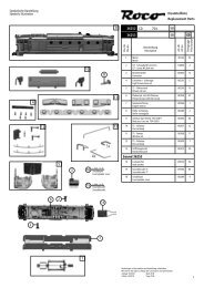
<strong>BETRIEBSANLEITUNG</strong><strong>GB</strong> <strong>Operating</strong> <strong>instructions</strong>FInstructions de serviceGEBR. FLEISCHMANN GMBH & CO. KGD-91560 Heilsbronn, GERMANYwww.fleischmann.de20 V ~D A CH ACHTUNG! Nicht für Kinder unter 3Jahren geeignet wegen funktions- und modellbedingterscharfer Kanten und Spitzen,Verschluckungsgefahr. <strong>GB</strong> WARNING! Notsuitable for children under 3 years of agedue to the functional sharp edges and pointsrequired in this model. Danger of swallowingF AVERTISSEMENT Ne convient pas pourdes enfants de moins de 3 ans, en raisondes fonctions d’utilisation et des formes àarêtes tranchantes du modèle. Dangerd’apsorption. NL WAARSCHUWING Nietgeschikt voor kinderen onder de 3 jaar vanwegefunktionele en/of modelgewenstescherpe randen en punten. Verslikkingsgevaar.I AVVERTENZA Non adatto ai bambinidi età minore di 3 anni a causa degli spigolie delle parti sporgenti. Pericolo di soffocamento.E ADVERTENCIA No apropriadopara niños de menos de 3 años, debido aque este modelo requiere cantos y puntosfuncionales agudos. Peligro de que sea ingerido.DK ADVARSEL Er ikke egnet til børnunder 3 år, p. g. a. funktions- og modelbetingedeskarpe kanter og spidser, - kan slugos.P AVISO Não conveniente para crianças sob3 anos devido às bordas agudas funcionais epontos exigiram neste modelo assim comoperigo de engolir. GR ΠΡОΣΟΧΗ. Τά πεχνιδια. αύτâ δένεπητρέποναι σέ παιδιά κάτο τών З χρόνων διότη ε´Ιναικοφτερα καί εχμηρά καί κùνδηνος νά τά καταπιουν SF VA-ROITUS Ei sovellu tukehtumisvaaran vuoksialle 3-vuotiaille lapsille. Sisältää toimivuudenja muotoilun kannalta oleellisia teräviä reunojaja piikkejä. S VARNING Inte ägnat förbarn under 3 år därför att där finns spetsoroch vassa kanter och fara för sväljning. CZVAROVÁNÍ Nevhodné pro dĕti do 3 let:funkční díly mají ostré hrany a špičky, nebezpečíspolknutí malých součástek a dílů.Uchovávejte a dodržujte toto upozornĕní. PLOSTREZEŻENIE Zabawka ze wzgledu nacechy dzialania, budowe modelu z ostrymikrawedziami oraz mozliwoscia polknieciamniejszych czesci nie jest przystosowana dladzieci ponizej 3 lat. SLO OPOZORILO Niprimerno za otroke do 3. leta starosti zaradifunkcionalno ostrih robov in konic, kot tudinevarnosti pozrtja.DCC-DECODER 685301DCC-DECODER 685401DCC-DECODER 685501SPECIFICATIONSThis DCC-DECODER is designed forinstallation in model railway locomotiveswhich are fitted with a digital connector portof standard NEM 651. Any other usage is notpermitted.PROPERTIES OF THE DCC-DECODERLocomotives with an inbuilt DCC-decodercan be run using the FLEISCHMANN controlequipment LOK-BOSS, PROFI-BOSS, multi-MAUS and the TWIN-CENTER 6802 as wellas with other DCC-controllers conforming tothe NMRA standard, without the need to alterthe DCC-decoder of the vehicle whenchanging from one system to another (withthe exception of loco addresses higher than”4“). With a DCC-decoder installed, thespeed of the loco remains constant, irrespectiveof the load, i. e. whether up or downhill,the loco will run at the same speed (allowingfor sufficient motive power).Max. size N: 12.9 x 9 x 3.4 mm · Load capacity:Motor 1000 mA, Light 200 mA ·Address: Elec tronically codeable · Specialfunction Light: Switchable On/Off, co-ordinatedwith direction of travel · Power Control:Speed unaffected by load · Accelerationand Braking Iner tia: Settable at several levels· Control Cha rac teristics: 2, settable · Motorand Light Output: Pro tec ted against shortcircuit · Overheating: Switches off whenoverheated · Sender function: Already integratedfor TRAIN-NAVIGATION.DCC-DECODER 685301DCC-DECODER 685401DCC-DECODER 685501DIGITAL-Adresse 3 (DCC-Standard-Adresse)DM 0.1 21/685301-0401BESTIMMUNGSGEMÄSSER GEBRAUCHDieser DCC-DECODER ist für den Einbau inModellbahnlokomotiven und Steuerwagenbestimmt.EIGENSCHAFTEN DES DCC-DECODERSLokomotiven mit eingebautem DCC-DE COderkönnen mit den FLEISCHMANN-Steuergeräten LOK-BOSS, PROFI-BOSS,TWIN-CENTER und multiMAUS als auch mitanderen DCC-Steuer geräten nach NMRA-Norm betrieben werden, ohne dass amDCC-Decoder des Fahrzeugs bei einemWech sel von einem zum anderen Sys temetwas eingestellt werden muss (AusnahmeLOK-BOSS: Lokadresse höher als „4“). Miteingebautem DCC-Decoder ist die Geschwindigkeit der Lok lastunabhängig, d. h.ob berg auf oder bergab, die Lok fährt immermit der gleichen Ge schwin digkeit (bei ausreichenderMotor leis tung).Maße (max.) N :12,9 x 9 x 3,4 mmBelastbarkeit Motor N 1000 mALicht 200 mAAdresseE l e k t r o n i s c hcodierbarSonderfunktionEin-/ausschaltbar,LichtLicht fahrtrichtungsabhängigLastregelungLastunab hängigeGeschwindigkeitAnfahr- undIn mehrerenBremsverzögerungStufen einstellbarMotorsteuerkennlinien 2, einstellbarMotorausgang,KurzschlussfestLichtausgangdurch AbschaltenÜbertemperaturSchaltet ab beiÜberhitzungSenderfunktionFür TRAIN-NAVIGATIONbereits integriertBei einem Problem schaltet der DCC-Decoderab und sig nalisiert darüber hinausdurch Blinken der Lok leuchten die Art desStörfalls:• Dauerndes Blinken:Kurz schluss• Doppelblinken:Überhitzung• Dreifachblinken:Summenstrom-überschreitungNach Beseitigung der Störquelle fährt dieLok weiter.Hinweis:Digitale DCC-Decoder sind hochwertigeErzeugnisse moderner Elek tro nik und mitbesonderer Sorgfalt zu behandeln:• Berührung mit Flüssigkeiten (z. B. Öl,Wasser, Reinigunsmittel …) gefährdenden DCC-DECODER.• Unsachgemäße Behandlung mit metallischenGegenständen (z. B. Schraubendreher, Pinzette …) kann denDECODERmechanisch/elektrischschädigen.• Grobe Behandlung (z.B. Ziehen an denLitzen, Bau teile biegen) kann mechanische/elektrische Schäden verursachen.• Löten am DCC-DECODER kann zumAus fall führen.WEGEN KURZSCHLUSSGEFAHR BEIMEINBAU BITTE UNBEDINGT BEACHTEN:• Vor dem Berühren des DCC-DECODERSgeerdeten Ge gen stand an fas sen (z. B.Heizkörper).• Da der DCC-DECODER im Be trieb Wärmeproduziert, muss er mit dem beiliegenden,elektrisch isolierenden Klebe strei fen aneine möglichst große Metall fläche ge klebtwerden.• Beim Ankleben bitte sorgfältig darauf achten,dass keine über den Kle be strei fen hinausstehendenDCC-DECODER- Teile mitMe tall in Be rührung kommen (eventuellKlebestreifen zuschneiden).• Achtung beim Einstecken des Decoder-Steckers in eine Schnittstellen-Buchse,die sich auf einem Motor-Lagerschildoder nahe am Fahrgestell befindet! Hierunbedingt darauf achten, dass es nichtzum Kurzschluss zwischen Stecker undLagerschild/Motor bzw. Fahrgestellkommt. Um die entsprechende Stellezu isolieren, liegt dem Decoder einzweiter Klebestreifen bei.EINBAU DES DCC-DECODERS1. Das Lok ge häuse gemäß der Lokbe triebsanleitung,die der Lok beiliegt, abnehmen.2. Den Gleichstromstecker aus der 6-poligendigitalen Schnitt stel le der Lok herausziehen.Den Ste cker gut aufheben!Damit lässt sich bei evtl. späteren Fehlernfeststellen, ob ein Fehler in der Lok oderim DCC-DECODER vorliegt.3. Den 6-poligen Stecker des DCC-DECODERS in die vorhandene Schnittstelleder Lok stecken. Hier bei daraufachten, dass die Mar kierung „1“ amStecker an der gleichen Kante wie die„1“ der Schnitt stelle liegt.4. Den DCC-DECODER mit Hilfe des bei -liegen den, dop pel seitigen Klebe streifenslagerichtig – d. h. mit dem größten Bauelementzur Klebefläche – an die vomHer ste l ler der Lok vorgesehene Stelleoder, falls nicht anders angegeben, aneine Me tall flä che mit guter Wär me ab leitungkleben. Hierbei zuerst den Kle bestreifenan die Metallfläche und dann denDCC-DECODER vorsichtig auf den Klebestreifendrücken.5. Das Lokgehäuse wieder aufsetzen. Dabeidarauf achten, dass die Litzen nicht eingeklemmtwerden.BETRIEB MIT DEM FLEISCHMANNDIGITAL-SYSTEMLokomotiven mit eingebautem DCC-DE-CODER können Sie mit dem FLEISCH-MANN-Steuergerät LOK-BOSS, PROFI-BOSS, multiMAUS und demTWIN-CENTER 6802 nach der NMRA-Norm betreiben. Welche DCC-De coderfunktionen Sie in welchem Umfang nutzenkönnen, wird vom Leis tungs umfangdes jeweiligen Steuer gerätesbe stimmt. Die in den je weiligen Be triebs -an lei tun gen unserer Steu er ge räte be -schriebenen Funk tio nen sind mit demDCC-DECODER voll nutzbar.Mit Steuergeräten nach der NMRA-Normist systembedingt der gleichzeitige,kompatible Fahr betrieb mit mehrerenGleichstromfahr zeu gen auf demselbenGleisabschnitt nicht möglich (s. a. Anleitungder jeweiligen Steuerung).CODIERUNG DER ADRESSEMit dem Steu er gerät TWIN-CENTER 6802,multiMAUS und PROFI-BOSS 686601 kanndie Adresse jeder zeit be liebig auf eine Adresse1 bis 9999, mit dem LOK-BOSS aufeine Adresse von 1 bis 4 geändert werden.Nähere Anweisungen finden Sie in derBetriebs anleitung, die dem jeweiligen Gerätbeiliegt.PROGRAMMIERUNG BEI DCCDer DCC-DE CO DER verfügt über eine Reiheweiterer Einstell mög lichkeiten und Informa -tionen, die sein Verhalten bestimmen bzw.Rückschlüsse auf sein Verhalten zulassen.Diese Informationen sind bzw. werden insogenannten CVs (CV = Configuration Variable)gespeichert. Es gibt CVs, die nur eineeinzige Infor ma tion (sog. „Byte“) speichern,aber auch solche, die 8 Infor ma tionseinheiten(Bits) be in halten. Die Bits werdenbei FLEISCHMANN von 0 bis 7 durchnummeriert.Bei der Programmierungbrauchen Sie diese Kenntnisse. Die benötigtenCVs haben wir Ihnen oben aufgelistet.Die Programmierung der CVs erfolgt vorzugsweisemit dem TWIN-CENTER, dermultiMAUS oder dem PROFI-BOSS oderanderen Geräten, die die Programmierung„CV-direkt“ byte- und bitweise beherrschen.Auch die Programmierung einiger CVs überdie Register-Programmierung ist möglich.Ferner können alle CVs byte-weise auf demHauptgleis, unabhängig vom Programmiergleis,programmiert werden, soweit ihr Steuergerätdiese Art der Programmierung (POM-Program on Main) beherrscht.(Weitere Informationen zu diesem Themaerhalten Sie in den Gerätehandbüchern undBetriebsanleitungen der jeweiligen Digitalsteuergeräte.)Die voreingestellten Grundwerte der CVskön nen mit dem TWIN-CENTER 6802, dermultiMAUS, dem PROFI-BOSS 686601 undanderen DCC-Steuergeräten nach NMRA-Norm umprogrammiert werden. Die Fahrzeugeverhalten sich dann entsprechend denneuen Vor gaben der geänderten CVs.FAHREN MIT GLEICHSTROMSie wollen ihre FLEISCHMANN DIGITAL-Lokeinmal auf einer Gleichstrom Anlage fahrenlassen? Kein Problem, im Lieferzustand sinddie entsprechenden CV-Variablen CV29 undCV12 bereits so eingestellt, dass unsereDCC Decoder auch auf „analogen“ Gleichstromanlagenfahren können. Natürlich könnenSie dabei nicht alle Highlights der digitalenTechnik genießen.MASSENSIMULATIONWir haben unseren DIGITAL-Loks Beschleunigungs-und Verzögerungswerte mitgegeben,die die Masse einer „echten“ Lok simulieren(siehe Tabelle oben). Oft ist es abervon Vorteil, einmal auf diese Simu lation verzichtenzu können, z. B. beim Kuppeln. Überdie Funktionstaste f5 kann dann die Beschleunigung/Verzögerungder Lok ein- undausgeschaltet werden.RANGIERGANGEinige Betriebssituationen erfordern einefeinfühlige Anpassung der Geschwindigkeit,den sog. Rangiergang. Über die Funktionstastef6 können Sie ihre DCC-Lok auf „halbeGeschwindigkeit“ setzen um bei gleichemRegelbereich feinfühliger rangieren zu können.HINWEIS ZUM AUSSCHALTEN DERDIGITAL-ANLAGEZum Ausschalten ihrer Modellbahn-Steuerungaktivieren Sie bitte zuerst die Nothalt-Funk tion des Steuer gerätes (siehe hierzu dieBetriebs an lei tung des Steuer gerä tes).An schlie ßend kann der Netzstecker derStromversorgung gezogen werden.In the event of a malfunction, the DCC-decoder switches itself off, and in addition,by blinking the loco lights will indicate thetype problem:Continual Blinking: Short CircuitDouble Blinking:O v e r h e a t i n gTriple Blinking:Current overloadOnce the cause of the problem has beensorted out, the loco will run once more.ADVICE:The digital DCC-DECODERS are highvalue products of the most modern electronics,and therefore must be handledwith the greatest of care: Liquids (i. e. oil,water, cleaning fluid ...) will damage theDCC-DECODER. · The DCC-DECODERcan be damaged both electrically ormechanically by unnecessary contactwith tools (twee zers, screwdrivers, etc.)· Rough handling (i. e. pulling on the wires,bending the components) can causemechanical or electrical damage · Solderingonto the DCC-DECODER can lead tofailure.Because of the possible short circuithazard, please take note of thesepoints during installation: Before handlingthe DCC-DECODER, ensure that you are incontact with suitable earth (i. e. radiator) ·Because the DCC-DECODER gets verywarm in operation, it must be fixed to thelargest available metal surface, using theNEMEinstecken des 6-poligen SteckersAnkleben des DecodersCV-WERTE BEIM FLEISCHMANN DCC-DECODERCV Name Grundwert Bedeutung1 Primäre Lokadresse 3 Bei DCC wirksam mit CV29 bit 5=0, Wert: 1–127.2 v min 3 Mindestgeschwindigkeit (Wertebereich: 0-255).3 Anfahr-Verzögerung 2 Verzögerungswert beim Anfahren.4 Brems-Verzögerung 2 Verzögerungswert beim Bremsen.5 v max 180 Maximale Geschwindigkeit (Wertebereich: 2-255).6 v mid 0 Mittlere Geschwindigkeit (keine Verwendung bei Wert 0, 1) für nichtlineareKennlinie.8 Hersteller ID 155 Lesen: NMRA-Hersteller-Identifikationsnummer. FLEISCHMANN hat155.Schreiben: Durch Programmieren dieser CV ist ein Reset einzelnerCVs auf die Werkswerte möglich. Beispiel: CV8 = 3 setzt die CV3 aufderen Werkswert.9 Motoransteuerung 20 0: Motorfrequenz 100 Hz, 15...22: Motorfrequenz 15...22 kHz11 Packet timeout 0 Zeit, nach der eine fahrende Lok ohne weitere Geschwindigkeitsbefehlegestoppt wird: Zeit = n *0,2s. Bei 0 keine Zeitüberschreitung.12 Fahrstromart Bit 0=1 Bit 0 = 1: Fahren mit Gleichstrom („analog“) möglich.Bit 0 = 0: Gleichstrombetrieb aus.17 Erweiterte Adresse 192 Oberer Anteil der erweiterten Adresse, Wert: 128–9999.(Oberer Teil) Wird wirksam bei DCC mit CV29 Bit 5=1, Wert: 128–9999.18 Erweiterte Adresse 0 Unterer Anteil der erweiterten Adresse, Wert: 128–9999.(Unterer Teil) Wird wirksam bei DCC mit CV29 Bit 5=1, Wert: 128–9999.29 Konfigurationswerte Bit 0=0 Bit 0: Mit Bit 0=1 wird die Fahrtrichtung des Fahrzeugs umgedreht.Bit 1=1Bit 1: Grundwert 1 gilt für Fahrgeräte mit 28/128 Fahrstufen.Für Fahrgeräte mit 14 Fahrstufen Bit 1=0 einstellen.Bit 2=1Fahrstromerkennung: Bit 2=1: Fahren mit Gleichstrom („analog“) möglich.Bit 2=0: Fahren mit Gleichstrom ausgeschaltet.Bit 4=0Umschalten zw. 3-Punkt-Kennlinie Bit4=0 und Fahrstufentabelle(Bit 4=1) in CV67-94.Bit 5=0 Bit 5: Zur Verwendung der erweiterten Adresse 128 – 9999 ist Bit 5=1einzustellen.30 Fehler-Information 0 Sobald ein Fehler auftritt wird dieser in CV30 gespeichert.Durch schreiben eines beliebigen Wertes kann die CV30 wiedergelöscht werden.Bit 0= 1: Kurzschluss L1 festgestelltBit 1= 1: Kurzschluss L2 festgestelltBit 6= 1: Kurzschluss Motor festgestelltBit 7= 1: Übertemperatur festgestellt33 Licht vorwärts 1 Zuordnung von interner zu externer Funktion (RP 9.2.2). Out 1: Lichtvorwärts34 Licht rückwärts 2 Out 2: Licht rückwärts35 F1 4 Out 336 F2 8 Out 437 F3 16 Out 538 F4 4 Out 639 F5 8 Out 7: Acceleration Zero40 F6 16 Out 8: Half Speed41 F7 32 Out 9: Train-Navigation (Wichtig: siehe CV63)42 F8 64 Out 1043 F9 16 Out 1144 F10 32 Out 1245 F11 64 Out 1346 F12 128 Out 1451 Individuelle Bit 0=1 Die lastunabhängige Fahrweise (Motorregelung) ist voreingestelltFLEISCHMANN- (Bit 0=1), kann aber auch ausgeschaltet werden (Bit 0=0).Einstellungen #1 Bit 6=1 Blinken der Lampen als Fehleranzeige von Kurzschluss, Überhitzungund Summenstromüberschreibung. Abschaltung der Blinkfunktiondurch Bit 6=0.64 RESET Das Schreiben einer 1 (CV64=1) setzt den Decoder auf die Werkssieheauchwerte zurück. Alle individuell geänderten Einstel lungen gehen verlo-Reset CV8ren. Ach tung: Manche Steuergeräte melden bei einem RESET einenFehler, führen ihn aber aus, andere nicht. Je nach Steuer gerät hilfteventuell mehrfaches Ausführen des RESET.Weitere Reset-Möglichkeiten:CV64=3: Fahrstufentabelle CVs 67...95, Trimwerte CVs 66, 95;CV64=4: 3-Punkt-Kennlinie CVs 2, 5, 6, Trimmwerte CVs 66, 95;CV64=6: Adressen, CVs 1, 17, 18, 29.66 Vorwärts Trimm 248 Hier sind die Geschwindigkeitswertein CV67-94 vom Grundwert248=100% prozentual einstellbar, z. B. 124=50%, Wert gilt f. Vor-wärtsfahrt.67 Veränderung der In jede der 28 CVs von 67 bis 94 kann ein Geschwindig keitswert zwibisRegelcharakteristik schen 0 und 255 eingegeben werden. In CV67 kommt die Mindest-,94 des Steuergeräts in CV94 die Höchst geschwin digkeit. Mit den Zwischenwerten ergebendiese die Steuerkennlinie. Sie bestimmt, wie sich die Fahrzeug -geschwindigkeit mit der Reglerstellung ändert.95 Rückwärts Trimm 248 Wie CV66, jedoch für Rückwärtsfahrt.105 Benutzervariablen 0 Werte zur freien Verwendung106 Benutzervariablen 0 Werte zur freien VerwendungEinstellen der Ausgänge als Lichtausgang bzw. Schaltausgang (Grundeinstellung)Funktion CV Wert Decoderausgang Beschreibung Einstellungen TeilwertLichtausgang /Schaltausgang120 0 Out 1: Licht vorwärts, f0v Betriebsart des Decoderausgangsist Licht-/Schaltausgang0: Ausgang ist Licht-/Schaltausgang130 0 Out 2: Licht rückwärts, f0rAnalog & DCCZuordnung121 8 Out 1: Licht vorwärts, f0v Helligkeit, Dimmwert desjeweiligen Ausganges:Bit 0-3: Das Licht kann in16 Stufen (0-15) gedimmtwerden.Parameter für Analog & DCCZuordnung: Bit 4-7:Bit 0: Helligkeit, Dimmwert: 1=ein, 0=ausBit 1: Helligkeit, Dimmwert: 1=ein, 0=ausBit 2: Helligkeit, Dimmwert: 1=ein, 0=ausBit 3: Helligkeit, Dimmwert: 1=ein, 0=ausBit 4: Funktion ist ein bei Fahrtrichtung: 0=Vorwärts, 1=RückwärtsBit 5: Ausgang ist von der Fahrtrichtung abhängig: 1=ein, 0=ausBit 6: Funktion gilt für: 1=DCC und Analog, 0=DCCBit 7:Funktion ist aktiv bei: 1=nur bei Fahrt, 0=bei Fahrt und Stillstand0/10/20/40/80/160/320/640/128131 8 Out 2: Licht rückwärts, f0rEinstellen der Ausgänge als Lichtausgang bzw. Schaltausgang mit BlinkfunktionFunktion CV Wert Decoderausgang Beschreibung Einstellungen TeilwertLichtausgang /Schaltausgang120 1 Out 1: Licht vorwärts, f0v Betriebsart des Decoderausgangsist Licht-/Schaltausgang mit Blinkfunktion1: Ausgang ist Licht-/Schaltausgang mit Blinkfunktion130 1 Out 2: Licht rückwärts, f0rAnalog & DCCZuordnung121 8 Out 1: Licht vorwärts, f0v Helligkeit, Dimmwert des jeweiligenAusganges:Bit 0-3: Das Licht kann in 16 Stufen(0-15) gedimmt werden.Parameter für Analog & DCC Zuordnung:Bit 4-7:Bit 0: Helligkeit, Dimmwert: 1=ein, 0=ausBit 1: Helligkeit, Dimmwert: 1=ein, 0=ausBit 2: Helligkeit, Dimmwert: 1=ein, 0=ausBit 3: Helligkeit, Dimmwert: 1=ein, 0=ausBit 4: Funktion ist ein bei Fahrtrichtung: 0=Vorwärts, 1=RückwärtsBit 5: Ausgang ist von der Fahrtrichtung abhängig: 1=ein, 0=ausBit 6: Funktion gilt für: 1=DCC und Analog, 0=DCCBit 7: Funktion ist aktiv bei: 1=nur bei Fahrt, 0=bei Fahrt und Stillstand0/10/20/40/80/160/320/640/128131 8 Out 2: Licht rückwärts, f0rBlinklicht 122 18 Out 1: Licht vorwärts, f0v Einschaltdauer des Ausgangs beiBlinkfunktion1-255: 0,1s-25,5s0: Licht, Schaltausgang dauernd ein132 18 Out 2: Licht rückwärts, f0r123 47 Out 1: Licht vorwärts, f0v Ausschaltdauer des Ausgangs beiBlinkfunktion1-255: 0,1s-25,5s0: Licht, Schaltausgang dauernd ein133 47 Out 2: Licht rückwärts, f0rAnzahl derBlink-/Schaltvorgänge124 0 Out 1: Licht vorwärts, f0v Anzahl der Blink- / Schaltvorgänge beiBlinklicht-/ Schaltfunktion. 1-255 Blink-/Schaltvorgänge werden bei jedem Auslösender Funktion am DCC-Steuergerät ausgeführt.Wenn die Funktion am Steuergerät beendetwird, wird der Vorgang abgebrochen, wennnoch nicht alle Blink-/ Schaltvorgänge zeitlichabgelaufen waren.1-255: 1-255 Blink-/ Schaltvorgänge0: Licht, Schaltausgang dauernd blinkend134 0 Out 2: Licht rückwärts, f0rDIMMEN UND EINSTELLEN DER LICHTAUSGÄNGEIn den CVs 121 und 131 können umfangreiche Einstellungen für die 2 Lichtausgänge vorgenommen werden. Bei einer Programmierung desGesamt-Wertes einer CV (byteweise Programmierung) sind die Teilwerte der entsprechenden Bit-Einstellungen zu addieren und gemeinsam zuprogrammieren. Die Ausgänge Out1, Out2 können in folgenden Betriebsarten verwendet werden: 1. Lichtausgang, 2. Lichtausgang mit Blinkfunktion.Wichtig: Für Out1 und Out2 gilt: Die Auswahl der Fahrtrichtung in CV121, bzw. CV131 Bit4 muss mit der Auswahl des Lichtausganges imFunction mapping CV33 und CV34 übereinstimmen. Anderenfalls heben die beiden Einstellungen sich gegenseitig auf. Der Decoder ist so eingestellt,das er Fahren mit Analog oder DCC automatisch erkennt. Die Lichtausgänge sind in der Voreinstellung nur bei DCC eingeschaltet. Dieswurde so gewählt, da im Analogbetrieb die Ausgänge nur dann richtig arbeiten, wenn die daran angeschlossenen LEDs oder Lampen gegen V+(blaue Litze des Decoders ) und nicht gegen die linke Schiene geschaltet werden.enclosed iso lating adhesive strip · Whengluing in position, please be careful toensure that no exposed parts of the DCC-DECODER can come into contact with anymetal (cut the adhesive strip to suit).Please take care when plugging in thedecoder plug into the decoder socketwhen it is situated on the motor faceplate,or around the bogie! It is essentialhere to ensure that there can be no shortcircuit between the plug and the motorface-plate/motor/bogie. In order to isolatethe relevant parts, there is a secondadhesive strip included with the decoder.FITTING THE DCC-DECODER1. According to the <strong>instructions</strong>, remove theloco body.2. Take out the D.C. plug from the 6-poledigital connector port in the loco (fullyremove the plug so that should an erroroccur later, it will be easier to discoverwhether the error lies in the loco or in theDCC-DECODER).3. Insert the 6-pole plug of the DCC-DECO-DER into the connector port of the loco.Please make sure that the marking ”1“on the plug is on the same edge as the”1“ on the connector part.4. With the aid of the included double-sidedadhesive strip, position the DCC-DECO-DER on the site prepared for it by the locomanufacturer, or in case none is available,CV-values of the FLEISCHMANN DCC-DECODERCV Name Basic value Meaning1 Loco address 3 On DCC effective with CV29 bit 5=0, value: 1–127.2 v min 3 Minimum speed (range of values: 0-255)3 Acceleration rate 2 Inertia Value when Accelerating (range of values: 0-255).4 Deceleration rate 2 Inertia Value when Braking (range of values: 0-255).5 v max 180 Maximum speed (range of values: 2-255).6 v mid 0 Medium speed (not in use when 0) for non-linear characteristic curve.8 Manufacturer ID 155 NMRA Identification No of Manufacturer. FLEISCHMANN is 155.If you program values into that CV, you can achieve a reset of certainCVs to the factory settings. Example: CV8 = 3 will reset CV3 to itsfactory setting.9 Motor control 20 0: motor frequency 100 Hz; 15-22: motor frequency 15-22 kHz11 Packet timeout 0 Time after which a running loco with missing running <strong>instructions</strong> willstop: time = n *0,2s. If 0, no timeout.12 Power source Bit 0=1 Bit 0 = 1: DC operation (”analog“) possible.conversionBit 0 = 0: DC operation off.17 Extended address 192 Upper section of additional adresses, value: 128–9999.(Upper section) Effective for DCC with CV29 Bit 5=1, value: 128–9999.18 Extended address 0 Lower section of additional adresses, value: 128–9999.(Lower section) Effective for DCC with CV29 Bit 5=1, value: 128–9999.29 Configuration Bit 0=0 Bit 0: With Bit 0=1 the direction of travel is reversed.variable Bit 1=1 Bit 1: Basic value 1 valid for controllers with 28/128 speed levels.For controllers with 14 speed levels use Bit 1=0.Bit 2=1Feed current detection: Bit 2=1: DC travel (analog) possible.Bit 2=0: DC travel off.Bit 4=0 Switching between 3-point-curve (Bit 4=0) and speed table (Bit 4=1)in CV67-94.Bit 5=0 Bit 5: For use of the additional addresses 128 – 9999 set Bit 5=1.30 Error information 0 If an error occurs, it will be stored in CV30. By writing any value toCV30 this content can be erased.Bit 0= 1: Short-circuit on L1 detectedBit 1= 1: Short-circuit on L2 detectedBit 6= 1:Short-circuit on Motor detectedBit 7= 1: Overtemperature detected33 Light forwards 1 Assignment internal to external function (RP 9.2.2). Out 1: Light forwards34 Light backwards 2 Out 2: Light backwards35 F1 4 Out 336 F2 8 Out 437 F3 16 Out 538 F4 4 Out 639 F5 8 Out 7: Acceleration Zero40 F6 16 Out 8: Half Speed41 F7 32 Out 9: Train-Navigation (Important: see CV63)42 F8 64 Out 1043 F9 16 Out 1144 F10 32 Out 1245 F11 64 Out 1346 F12 128 Out 1451 Individual Bit 0=1 The load independent running (motor control) is preset (Bit 0=1)FLEISCHMANN- Can be switched off also (Bit 0=0).settings #1 Bit 6=1 Blinking of lights to indicate short circuit, overheating or current overload.Switching off this function with Bit 6=0.64 RESET Writing a 1 (CV64=1) resets the Decoder to the factory settings. Allsee alsoindividual adjustments will le lost. Attention: Some controllers will in-Reset CV8dicate an error on RESET, but will carry it out, others will not.Depending on the respective controller, repeated action of the RESETwill assist.Further possible resets:CV64=3: Speed step table CVs 67-95, trim values CVs 66, 95;CV64=4: 3-point-curve CVs 2, 5, 6, trim values CVs 66, 95;CV64=6: addresses, CVs 1, 17, 18, 29.66 Forward trim 248 Here, the speed values contained in CV67-94 can be adjusted by apercentage from 248=100%. E.g. 124=50%. Value valid for runningforward.67 Adjustment of A speed between 0 and 255 can be given in each of the 28 CVs fromto control characteristic 67 to 94. CV67 holds the minimum speed, and CV94 holds the top94 curve of controller speed. The control characteristic curve is then determined by intermediate values. They decide how the speed of the vehicle alters withthe controller setting.95 Backwards trim 248 As CV66, but for running backwards105 User variables 0 Values free to use106 User variables 0 Values free to usethen on a metal surface with good heatconducting capabilities. First of all placethe adhesive strip on the metal surface,and then carefully place the DCC-DECO-DER onto the adhesive strip.5. Replace the loco body, making sure thatthe wires are not squeezed.OPERATION WITH THEFLEISCHMANN DCC-DIGITAL SYSTEMLocos with inbuilt DCC-DECODER can beused with the FLEISCHMANN-controllersLOK-BOSS, PROFI-BOSS and TWIN-CENTER 6802 conforming to the NMRAstandard. Which DCC-decoder functionscan be used within which parameters arefully described in the respective operating<strong>instructions</strong> of the respective controller.The prescribed functions shown in theinstruction leaflets included with our controllersare fully useable with the DCC-decoder. The simultaneous, compatiblerunning possibilities with D.C. vehicles onthe same electrical circuit is not possiblewith DCC controllers conforming toNMRA standards (see also manual of therespective controller).CODING THE ADDRESSUsing the controller TWIN-CENTER 6802,multiMAUS and the PROFI-BOSS theaddress can be altered at any time fromaddress 1 to 9999. Using the LOK-BOSS theaddress can be altered at any time toaddress 1 through 4. Please make yourselffamiliar with the <strong>instructions</strong> which are includedwith each piece of equipment.PROGRAMMING WITH DCCThe DCC-decoder enables a range of furthersettable possibilities and information accordingto its characteristics. This information isstored in so-called CVs (CV = ConfigurationVariable). There are CVs which store only asingle information, the so-called Byte, andothers that contain 8 pieces of information(Bits). For FLEISCHMANN, the Bits are numberedfrom 0 to 7. When programming, youwill need that knowledge. The CVs requiredwe have listed for you (see CV table).Programming of the CVs is mainly done withthe TWIN-CENTER, PROFI-BOSS, multi-MAUS or similar appliances, that are capableof the programming by bits and bytes inmode ‘CV direct’. The programming of someCVs by register-programming is also possible.Furthermore, all CVs can be programmedbyte-wise on the main track, independentlyfrom the programming-track.However, this is possible only if your applianceis capable of this programming-mode(POM - program on main).Further information concerning that issue isgiven in the respective manuals and operating<strong>instructions</strong> of the digital controllers.The pre-adjusted basic values of the CVs canbe altered by use of the TWIN-CENTER,PROFI-BOSS, multiMAUS and other DCCcontrollers that accord to NMRA standards.The vehicles will then behave according tothe values that you have set within the CVs.RUNNING ON CONVENTIONALDC LAYOUTSYou want to run your FLEISCHMANN DCClocoonce in while on a DC layout? No problemat all, because as delivered, we haveadjusted the respective CV29 and CV12 inour decoders so that they can run on ”analog“layouts as well! However, you may notbe able to enjoy the full range of digital techniquehighlights.SIMULATION OF TRAIN WEIGHTIn our decoders we have integrated accelerationand braking inertia values, that representthe weight of a ”real“ locomotive (see CV-table).Often, however it is of advantage to beable to switch off this simulation, e.g. whencoupling. The inertia can then beswitched on and off using the function key f5.SHUNTING GEGARSome operational situations require delicatespeed adaption, often called ‘shunting gear’.By using the f6 function key, you can set yourDCC-loco to ”half speed“ with increasedspeed levels in order to make the shunting farmore finely controllable.ADVICE ON SWITCHING THE DIGITALLAYOUT ON AND OFFTo switch off your model railway controller,first of all activate the emergency stop functionof the controller (see <strong>instructions</strong> with thecontroller). Then finally, pull out the mainsplug of the controller power supply; otherwiseyou might damage the appliance. If youignore this critical advice, damage could becaused to the equipment.DIMMING AND ADJUSTMENT OF LIGHT OUTPUTSIn the CVs 121 and 131, you can carry out various adjustments of the light outputs. If you program the total value of a CV (byte-wise programming),each partial value of the adjusted bit must be added and programmed together. The outputs Out1, Out2 may be used in the followingoperation modes: 1. Light output, 2. Light output with blinking function. Important: For Out1 and Out2 each: The selection of the running directionin CV121, resp. CV131 Bit4 must be identical with the selection of the light output in the function mapping of CV33 and CV34. Otherwiseboth adjustments will annulate each other. The decoder is adjusted to automatically detecting analog or DCC operation. The light outputs arepre-adjusted active only in DCC operation. We made that adjustment, because, in analog operation, the outputs will work correctly only, if thethe connected LEDs or lamps are switched to V+ (blue line of the decoder ) and not against the left-side of the track.Adjusting the Outputs as Light outputs resp. Switching outputs (Basic setting)Function CV Value Decoder output Description Settings Part valueLight output/switchingoutput120 0 Out 1: Light forward, f0v Operation mode of decoderoutput is light-/ switchingoutput0: output is light-/switch-output130 0 Out 2: Light backward, f0rAnalog & DCCassignment121 8 Out 1: Light forward, f0v Brightness, dim value ofresp. output:Bit 0-3: The light can bedimmed in 16 steps (0-15)Parameter for analog & DCCassignment: Bit 4-7:Bit 0: Brightness, dim value: 1=on, 0=offBit 1: Brightness, dim value: 1=on, 0=offBit 2: Brightness, dim value: 1=on, 0=offBit 3: Brightness, dim value: 1=on, 0=offBit 4: Function is on in direction: 0=forward, 1=backwardBit 5: Output depends on direction: 1=on, 0=offBit 6: Function valid for: 1=DCC and analog, 0=DCCBit 7: Function is active at: 1=only when running, 0=running and stand-still0/10/20/40/80/160/320/640/128131 8 Out 2: Light backward, f0rAdjusting the Outputs as Light outputs resp. Switching outputs with blinking functionFunction CV Value Decoder output Description Settings PartvalueLight output/switchingoutput120 1 Out 1: Light forward, f0v Operation mode of decoder output islight-/ switching output with blinkingfunction1: output is light-/switch-output with blinking function130 1 Out 2: Light backward, f0rAnalog & DCCassignment121 8 Out 1: Light forward, f0v Brightness, dim value of resp. output:Bit 0-3: The light can be dimmed in 16steps (0-15)Parameter for analog & DCC assignment:Bit 4-7:Bit 0: Brightness, dim value: 1=on, 0=offBit 1: Brightness, dim value: 1=on, 0=offBit 2: Brightness, dim value: 1=on, 0=offBit 3: Brightness, dim value: 1=on, 0=offBit 4: Function is on in direction: 0=forward, 1=backwardBit 5: Output depends on direction: 1=on, 0=offBit 6: Function valid for: 1=DCC and analog, 0=DCCBit 7: Function is active at: 1=only when running, 0=running and stand-still0/10/20/40/80/160/320/640/128131 8 Out 2: Light backward, f0rBlinking light 122 18 Out 1: Light forward, f0v Switch-on duration of output withblinking function1-255: 0,1s-25,5s0: Light, switch-output permanently on132 18 Out 2: Light backward, f0r123 47 Out 1: Light forward, f0v Switch-off duration of output withblinking function1-255: 0,1s-25,5s0: Light, switch-output permanently on133 47 Out 2: Light backward, f0rNumber ofblink-/switchcycles124 0 Out 1: Light forward, f0v Number of blink-/switch-cycles with blinkinglight-/switch-function. 1-255 blink-/switchcycles are carried out with each funktiontransmitted by the DCC controller. If the functionis stopped by the controller, the procedure isended, even if there is a rest of cycles.1-255: 1-255 blink-/ switch cycles0: Light, switch-output permanently blinking134 0 Out 2: Light backward, f0rplug in the 6-pole plugglue the decoder with adhesive strip
DCC-DECODER 685301DCC-DECODER 685401DCC-DECODER 685501UTILISATION CONFORMECe DCC-DÉCODEUR est destiné à êtreintégré aux locomotives en modèle réduitéquipées d’un connecteur digital NEM 651.Toute autre utilisation est interdite.PROPRIETES DU DÉCODEUR DCCLe DÉcodeUr DCC peut s’utiliser aussibien avec les commandes LOK-BOSS,PROFI-BOSS, multiMAUS et TWIN-CENTER6802 qu’avec les commandes DCC au standardNMRA, sans qu’aucun réglage du DÉcodeUrDCC du véhicule ne soit nécessaireen cas de changement d’un système àl’autre. Equipée d’un DÉcodeUr DCC, la locomotiveest indépendante de la charge,c’est-à-dire que peu importe si elle monte oudescend, elle roulera toujours à la mêmevitesse (si la puissance du moteur est suffisante).Dimensions N (max.) : 12,9 x 9 x 3,4 mm ·Charge ad missible : Moteur 1000 mA, Eclairage200 mA · Adresse : Encodage électronique· Fonction spéciale éclairage : Commutable,éclairage en fonction du sens de lamarche · Régu lation en fonction de la charge :Vitesse indépendante de la charge · Accélérationet freinage réglables : Réglage sur différentsni ve aux · Courbe caractéristique decommande: 2, réglables · Sortie moteur :Protégée contre les courts- circuits par coupurede l’alimenta tion · Decodeur : Protégércontre surchauffage par coupure del’alimentation · Fonction d’emetteur de navigation(TRAIN-NAVIGATION) intégré.En cas d’un défaut, le DÉcodeUr DCC semet hors circuit et signale en outre la naturede la panne en faisant clignoter les ampoulesde la locomotive:clignotement continu : court-circuitclignotement double :clignotement triple :sur chauffagesur charge decourantUne fois la cause de la panne élimin ée, lalocomotive poursuit sa route.INDICATION IMPORTANTLes DÉCODERS DCC digitaux étant desproduits électroniques de pointe, ils doiventêtre manipulés avec le plus grandsoin : Tout contact avec un liquide (par ex.huile, eau, produit nettoyant etc.) comprometle bon fonctionnement du DÉ-CODEURS DCC · Toute mani pulation nonconforme avec des objets métalliques(par ex. tournevis, pincette etc.) peutendommager le DÉCODEUR DCC sur leplan mécanique ou électrique · Une manipulationbrutale (par ex. en tirant sur lesfils ou en tordant les composants) peutendommager l’appareil sur le plan mécaniqueou électrique · Tout travail desoudage sur le Dècodeur DCC peut ledétériorer.RISQUE DE COURT CIRCUIT – VEUILLEZABSOLUMENT OBSERVER LES CONSIG-NES SUIVANTES :Avant de saisir le DCC-DÉCODEUR, toucherun objet mis à la terre (par ex. radiateur). · LeDCC-DÉCODEUR produisant de la chaleuren fonctionnant, il doit être collé à l’aide duruban adhésif (isolant électrique) fourni surune surface métallique qui soit la plusgrande possible. · Au collage, veillez à cequ’aucune partie du DCC-DÉCODEUR dépassantdes rubans adhésifs n’entre encontact avec le métal (si nécessaire, recoupezà longueur le ruban adhésif).Attention lors du branchement de lafiche du décodeur dans une prised’interface se situant sur le carter dumoteur ! Dans ce cas, veillez absolutementà éviter tout court circuit entre lafiche et le carter du moteur/moteur/châssis. Pour isoler la partie corres-pondante,le décodeur est fourni avec undeu xième ruban adhésif.MONTAGE DU DCC-DÉCODEUR1. Retirer le boîtier de la locomotive suivantles <strong>instructions</strong> fournies avec cette dernière.2. Débrancher la fiche à courant continu duconnecteur digital à 6 pôles de la loco(bien tirer la fiche). Cela permet par lasuite de détecter en cas d’éventuellespannes si le défaut vient de la loco ou duDCC-DÉCODEUR.3. Brancher la fiche à 6 pôles du DCC-DÉCODEUR sur le connecteur existant dela loco. Ici, veiller à ce que le repère ”1“ dela fiche soit en regard du repère ”1“ duconnecteur.4. Coller à l’aide du ruban adhésif doubleface fourni le DCC-DÉCODEUR àl’endroit prévu par le fabricant de la locoou, à défaut, sur une surface métalliquedissipant bien la chaleur. Pour cela, collerd’abord l’adhésif sur la surface métalliqueavant d’y disposer soigneusement leDCC-DÉCO DEUR.5. Remonter le boîtier de la loco en veillant àne pas coincer les fils.FONCTIONNEMENT AVEC LESSYSTE MES FLEISCHMANN DCC-DIGITAL:Le DÉCODEUR DCC fonctionne avec toutesles commandes centrale LOK-BOSS,PROFI-BOSS, multiMAUS et TWIN-CEN-TER 6802. Les fonctions décrites dans les<strong>instructions</strong> de service de ces commandessont toutes exploitables avec le DècodeurDCC. Avec les centrales de commandeDCC normalisées NMRA, lesystème lui-même n'autorise pas la tractionsimultanée compatible de plusieursvéhicules à courant continu sur le mêmetronçon de voie (voir <strong>instructions</strong> de servicede la commande en question).ENCODAGE DE L’ADRESSEAvec le commande TWIN-CENTER 6802,multiMAUS et PROFI-BOSS 686601,l’adresse peut être modifiée à tout momentsur un chiffre compris entre 1 et 9999. Avecle commande LOK-BOSS, l’adresse peutêtre modifiée à tout moment sur un chiffrecompris entre 1 et 4. Pour cette opération,veuillez vous reporter aux <strong>instructions</strong> deservice fournies avec la commande en question.PROGRAMMATION DCCLe DÉCODEUR DCC dispose d’une série depossibilités de réglages et d’informationssupplémentaires qui déterminent son comportementou qui permettent d’en tirer desconclusions. Ces informations sont ou sontappelées à être mémori sées dans des dénomméesCV (Configuration Variable). Il y ades CV qui ne mémorisent qu’une seule information(octet) comme il y en a d’autresqui en contiennent 8. Ces informations sontstockées dans des dé nommés Bits. CesBits sont numérotés par FLEISCHMANN de0 à 7.La programmation des CV est fait principalementavec le TWIN-CENTER, PROFI-BOSS,multiMAUS ou les appareils similaires, celaest capable de la programmation en mode‘CV direct’ en Bits et en octets. La programmationde quelques CV par la registre-programmationest aussi possible. De plus, tousles CV peuvent être programmés par octetssur la piste principale, d'une manière indépendantede la piste à programmation. Cependant,ceci est possible seulement sivotre appareil est capable de ce mode deprogrammation POM (‘Program on main’).Pour la programmation, il vous faut cesrenseignements. Nous vous avons listé lesCV nécessaires. Plusieurs information voirles manuels et les <strong>instructions</strong> de service aucommandes numeriques. Les valeurs assignéesaux CV peuvent être reprogramméesavec le TWIN-CENTER 6802, multiMAUS etPROFI-BOSS 686601 et d’autres commandesDCC normalisées NMRA. Ensuite, lesvéhicules se comportent suivant les nouveauxparamètres des CV modifiés.TRACTION EN COURANT CONTINUVous souhaitez tracter une fois votre locoFLEISCHMANN DIGITAL sur un réseau àcourant continu ? Pas de problème : à lalivraison, les variables des CV29 et CV12sont réglées de sorte à permettre à nosdécodeurs DCC de fonctionner aussi surdes réseaux ”analogiques“ à courant continu.Bien entendu, vous ne pourrez alorspas profiter de tous les avantages de latechnique digitale.SIMULATION DE L’INERTIENous avons préprogrammé nos locosdigitales avec des valeurs de retard àl’accélération et au freinage simulant l'inertied'une ”véritable“ loco (voir tableau). Souvent,vous verrez qu’il est avantageux depouvoir neutraliser cette simulation, par ex.pour atteler des véhicules. La touche defonction f5 vous permet ensuite d’activer etde désactiver l’accélération/le freinage de laloco.VITESSE DE TRIAGECertaines situations de conduite exigent unajustement en finesse de la vitesse avec ladénommée vitesse de triage. La touche defonction f6 vous permet de faire passervotre loco DCC à la ”vitesse lente“ et depouvoir réaliser des opérations de triageavec la même plage de réglage, mais plusfine de la vitesse.CONSIGNES POUR METTREL’INSTALLATION DIGITAL HORS CIRCUITAvant d’éteindre l’installation, activer la fonctiond’arrêt d’urgence de la commande (seréférer pour cela aux <strong>instructions</strong> de servicede la commande). Débrancher ensuite laprise secteur du transfo. La non-observationde cet avertissement de danger peut entraînerla détérioration de l'appareil.Valeurs CV de DÉCODEUR DCC FLEISCHMANNCV Nom Valeur de base Description1 Adresse loco (prim.) 3 Activée sur DCC avec CV29 bit 5=0, valeur : 1–127:2 v min 3 Vitesse minimale (domaine des valeurs : 0-255).3 Retard à l’accélération 2 Valeur de retard d’accélération (domaine des valeurs : 0-255).4 Retard au freinage 2 Valeur de retard de freinage (domaine des valeurs : 0-255).5 v max 180 Vitesse maximale (domaine des valeurs : 2-255).6 v mid 0 Vitesse moyen (aucun emploi par valeur 0) pour caractéristique nonlinéaire.8 ID du fabricant 155 Lire : <strong>Fleischmann</strong> ID, attribué par NMRA. Ècrire : RESET des CVsindividuelles aux valeurs usine, p ex. : CV8=3 repose CV3 sur lavaleur usine.9 Pilotage moteur 20 0: PWM off, resp. frequence moteur 100 Hz, 15-22 : frequence mot.15-22 kHz11 Packet timeout 0 Temps, après une loco roulant est arrêtée sans des <strong>instructions</strong> demarche :Temps = n *0,2s. Si 0 pas de timeout.12 Type de courant Bit 0=1 Quel est le protocole active en plus de DCC :Bit 0 : Analogue 1=on, 0=off Bit 1...4 : toujour 0 Bit 5 : FMZ, touj. 0Bit 6...7 : toujour 017 Adresse longue 192 Partie supérieure de l’adresse étendue, valeur : 128–9999.(partie supérieure) Est activée sur DCC avec CV29 Bit 5=1, valeur : 128–9999.18 Adresse longue 0 Partie inférieure de l’adresse étendue, valeur : 128–9999.(partie inférieur) Est activée sur DCC avec CV29 Bit 5=1, valeur : 128–9999.29 Valeurs de Bit 0=0 Bit 0: avec Bit 0=1, inversion du sens de la marche du véhicule.configuration #1 Bit 1=1 Bit 1: la valeur par défaut 1 s’applique aux véhicules à 28/128 niveauxde conduite.Pour les véhicules à 14 niveaux de conduite, régler sur Bit 1=0.Bit 2=1 Caractéristique du courant de traction : Bit 2=1: traction en courantcontinu (”analogique“) possible. Bit 2=0 : traction en courant continudésactivée.Bit 4=0 Choisir la caract. à 3 points (Bit 4=0) ou tableau de vit. (Bit 4=1) entreles CV67-94.Bit 5=0 Bit 5 : pour utiliser l’adresse étendu 128 – 9999 régler sur Bit 5=1.30 Information d’erreur 0 Si un erreur existe, il est sauvé entre CV30. Par ècrire d'un valeurquelconque la CV30 peut être supprimé.Bit 0= 1 : Court-circuit L1 (Out 1) trouvéBit 1= 1 : Court-circuit L2 (Out 2) trouvéBit 6= 1 : Court-circuit moteur trouvéBit 7: 1 : Surchauffage trouvé33 Feu avant 1 Matrice pour afectation de fonction interne à externe (RP 9.2.2).Out 1 : Feu avant34 Feu arrière 2 Out 2 : Feu arrière35 F1 4 Out 3 :36 F2 8 Out 4 :37 F3 16 Out 5 :38 F4 4 Out 6 :39 F5 8 Out 7 : accélération zero40 F6 16 Out 8 : demi vitesse41 F7 32 Out 9 : Train-Navigation (important : voir CV 63)42 F8 64 Out 10 :43 F9 16 Out 11 :44 F10 32 Out 12 :45 F11 64 Out 13 :46 F12 128 Out 14 :51 Fonctions Bit 0=1 Le traction indépendante de la charge (régulation moteur) est préré-FLEISCHMANNglée (Bit 0=1), cette fonction pouvant cependant être désactivéeindividuelles #1 (Bit 0=0).Bit 6=1 Clignotement des ampoules signalant une panne court-circuit,surchauffage ou surcharge de courant. Annulation de la fonction declignotement avec Bit 6=0.64 RESET 0 Ne peut pas être modifiée. La saisie d’un 1 (CV64=1) restaure les vavoiraussileurs par défaut du décodeur. Tous les réglages personnalisés sont perdus.Reset CV8Attention : certaines commandes signalent une panne pendant leRESET tout en exécutant ce dernier, d’autres non. Selon la commande,il sera éventuellement utile d’effectuer le RESET à plusieursreprises. Autres possibilités RESET :CV64=3: Tableau des niveaux de conduite CV 67-94, valeursd’adaptation de la vitesse CV 66, 95; CV64=4: Courbe caractéristiqueà 3 points CV 2, 5, 6, valeurs d’adaptation de la vitesse CV 66,95; CV64=6: adresses, CVs 1, 17, 18, 29.66 Adaptation de la 248 Ici, les valeurs des vitesses peuventt être modifieés par CV67-94 envitesse avantpourcentage de valeur de base 248=100% a , p. ex. 124=50%, valeurêtre valable p. marche avant.67 Modification de la Chaqune des 28 CV de 67 à 94 autorise l’entrée d’une vitesse compriseà caractéristique de entre 0 et 255.94 commande (courbe La CV67 reçoit la vitesse minimum, la CV94 la vitesse maximale. Assocaractéristique)ciées aux valeurs de reglage de la intermédiaires, ces vitesses constituentla courbe caractéristique de commande.Celle-ci détermine la manière dont change la vitesse du véhicule enfonction de la position du régleur.95 Ajustage marcher arr. 248 Comme CV66, mais pour la marche arrière.105 Variables client 0 Valeurs pour une utilisation libre106 Variables client 0 Valeurs pour une utilisation libreBrancher la fiche à 6 pôlesColler le decodeurTable d'ajustements de base aux sorties (outputs) utilisés à sorties lumineuses ou sorties à commutation :Ajustement des sorties aux sorties lumières ou sorties à commutation (ajustement de base)Fonction CV Valeur Sortie décodeur Description Ajustements Val. partialSortie lumineuse/SortieàcommutationAffectationanalogue etDCC120 0 Out 1 : feu avant, f0v Mode d'operation du 0 :Sortie est Sortie lumineuse/Sortie à commutationdécodeur est Sortie lumineuse/Sortie130 0 Out 2 : feu arrière, f0rà commutation12113188Out 1 : feu avant, f0vOut 2 : feu arrière, f0rLuminosité, valeur baisséepar sortie: Bit 0-3: Laluminosité peut être ajustéepar 16 niveaux (0-15)Paramètre pour affectationanalogue & DCC : Bit 4-7:Bit 0: Luminosité, valeur baissée : 1=on, 0=offBit 1: Luminosité, valeur baissée : 1=on, 0=offBit 2: Luminosité, valeur baissée : 1=on, 0=offBit 3: Luminosité, valeur baissée : 1=on, 0=offBit 4: Fonction active en marche : 0=avant, 1=arrièreBit 5: Sortie dépend de la direction de conduite : 1=on, 0=offBit 6: Fonction valable pour : 1=DCC et analogue, 0=DCCBit 7: Fonction active en : 1=marche seulement, 0=en marche et à l'arrêtAjustement des sorties aux sorties lumières ou sorties à commutation avec fonction clignotantFonction CV Valeur Sortie décodeur Description Ajustements Val. partialSortie lumière/Sortie àcommutationAffectationanalogue etDCCLumièreclignotantNombredes cyclesclignotement/cycles decommutation120 1 Out 1 : feu avant, f0v Mode d'operation du décodeur est Sortielumière/Sortie à commutation avec130 1 Out 2 : feu arrière, f0r fonction clignotant12113188Out 1 : feu avant, f0vOut 2 : feu arrière, f0rLuminosité, valeur baissée par sortie:Bit 0-3: La luminosité peut être ajustéepar 16 niveaux (0-15)Paramètre pour affectation analogue &DCC : Bit 4-7:122 18 Out 1 : feu avant, f0v Durée switch-on de la sortie en fonctionde clignotement.132 18 Out 2 : feu arrière, f0r123 47 Out 1 : feu avant, f0v Durée switch-off de la sortie en fonctionde clignotement.133 47 Out 2 : feu arrière, f0r12413400Out 1 : feu avant, f0vOut 2 : feu arrière, f0rNombre de cycles clignotants/commutationsenfonction de sortie clig./comm.1..255 cycles clig./comm. sont exécutésà chaque déclenchement de la fonctionau niveau du centrale DCC. Si la fonctionest résilié à la centrale, l'opération estannulée même si tous les cycles clig./comm. n'étaient pas encore finis.1: Sortie est Sortie lumineuse/Sortie à commutation avec fonctionclignotantBit 0: Luminosité, valeur baissée : 1=on, 0=offBit 1: Luminosité, valeur baissée : 1=on, 0=offBit 2: Luminosité, valeur baissée : 1=on, 0=offBit 3: Luminosité, valeur baissée : 1=on, 0=offBit 4: Fonction active en marche : 0=avant, 1=arrièreBit 5: Sortie dépend de la direction de conduite : 1=on, 0=offBit 6: Fonction valable pour : 1=DCC et analogue, 0=DCCBit 7: Fonction active en : 1=marche seulement, 0=en marche et à l'arrêt1-255: 0,1s-25,5s0: Lumière, sortie de commutation en permanence1-255: 0,1s-25,5s0: Lumière, sortie de commutation en permanence1-255: 1-255 cycles de clignotement/cycles de commutation0: Lumière, sortie de commutation clignoté en permanenceAJUSTEMENTS DES SORTIES DE FEUDans les CV 121 et 131, (voir Table d'ajustements de base aux sorties (outputs) utilisés à sorties lumineuses ou sorties à commutation)vous pouvez exécuter de divers ajustements aux le deux sorties d’illumination. Si vous programmez la valeur totale d'un CV (en programmationpar octets), chaque valeur partielle du bit ajusté doit être ajoutée et doit être programmée ensemble. Les sorties Out1, Out2 peuvent être utilisésdans les modes suivants : 1. Sortie lumière, 2. Sortie lumière clignotant. Important : Pour Out1 et Out2 est valable: Le choix de la direction enCV121, CV131 Bit 4 doit correspondre avec la sélection de sortie lumière dans les CV33 et CV34 («function mapping»). Sinon, les deux réglagess'annulent. Le décodeur peut reconnaître la conduite analogique ou DCC automatiquement. Les sorties de la lumière peuvent être allumés pardéfaut uniquement pour l'operation DCC. Cela a été choisi de manière, que les sorties analogiques à travailler correctement, seulement si leslampes ou LED's seront connectés à V + (fil bleu du décodeur) et ne pas sont connectées sur le rail de gauche.0/1,0/2,0/4,0/80/16,0/320/640/1280/1,0/2,0/4,0/80/16,0/320/640/128