InstallatIon · Manual 4.0012 1/4 - Wibre
InstallatIon · Manual 4.0012 1/4 - Wibre
InstallatIon · Manual 4.0012 1/4 - Wibre
- No tags were found...

You also want an ePaper? Increase the reach of your titles
YUMPU automatically turns print PDFs into web optimized ePapers that Google loves.
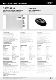
Installation · <strong>Manual</strong><strong>4.0012</strong>Einbau-Unterwasser-Scheinwerfer aus V4A-EdelstahlRecessed Underwater-Light out of 316L stainless steelProjecteur immergeable encastré en INOX 316LIP68V4AEDELSTAHLINKLKABELINKL5 MEPOL3 36min 2020506080503368020 min 20ø 50 ø 50601. AnwendungMiniatur-Scheinwerfer (ø 35 mm) komplett aus V4A-Edelstahl1.4571 für die Wand- und Bodenmontage zur Akzentuierungin kleineren Schwimmbädern und Whirlpools, aber auch zurBeleuchtung in Dusch- und Wellnessbereichen oder Wasserspielenund Springbrunnen.Sonderkonstruktionen-/ anwendungen auf Anfrage.2. Technische Daten/Konstruktion· Scheinwerfer (ø 35 mm) komplett aus V4A-Edelstahl 1.4571· Schutzart IP68 – Wassertiefe bis 5 m· runde Aufsatzblende (H 3 mm, ø 50 mm), V4A,oder quadratische Aufsatzblende (H 3 mm, 50 x 50 mm), V4A· 1 POW-LED 350 mA (TLF 140 Lm/LED) oder 1 Multichip RGB 350 mA· rotationsymmetrische Lichtverteilung monochrom 10°, RGB 120°· Kabeldruckverschraubung, V4A Edelstahl· für den Wand- und Bodeneinbau mittels Einbaugehäuse ausV4A-Edelstahl, mit 1,5 m Kabelschutzrohr und Abschlußstutzen,geeignet für Betonbecken mit Fliesenauskleidung (max. 25 mmFliesen-/Mörtelaufbau), Edelstahlbecken (Schweißflansch), Beckenmit Klebe-/Folienanstrich (Klebeflansch) und Betoneinbau imFußbodenbereich (ohne Schalungsflansch)· Lieferung mit 3 m Silikonkabel· Gewicht: Leuchte 0,5 kg, Einbaugehäuse 1,0 kg1. ApplicationCompact spotlight (ø 35 mm) made completely of V4A stainless steel1.4571 for wall and floor mounting for accentuation in smaller swimmingpools and whirlpools, but also for lighting in shower and wellness areas orwater displays and fountains.Special designs/applications on request.2. Technical Details/Construction· spotlight (dia. 35 mm) made entirely of V4A stainless steel 1.4571· Degree of protection IP68 – for water depth up to 5 m· round attachment cover (H 3 mm, dia. 50 mm), V4A,or square attachment cover (H 3 mm, 50 x 50 mm), V4A· 1 POW LED 350 mA (TLF 140 Lm/LED) or 1 Multichip RGB 350 mA· Rotationally symmetric light distribution, monochrome 10°, RGB 120°· Cable pressure sleeve, V4A stainless steel· for wall and floor installation using installation housing made of V4Astainless steel, with 1.5 m cable protection tube and connection socket,suitable for concrete pools with tile covering (max. 25 mm tile/mortarthickness), stainless steel pools (welded flange), pools with adhesive/foil coatings (adhesive flange) and concrete installation in the floor area(without sheathing flange)· supplied with 3m of silicon cable· Weight: Light 0,5 kg, installation housing 1.0 kg1. ApplicationProjecteur miniature (ø 35mm) complet en acier inoxydable V4A 1.4571pour le montage dans la paroi ou le fond et la réalisation d‘effets de lumièredans les petites piscines et les jacuzzis, mais également pour l‘éclairagedes espaces de douches et spa, ou encore les animations aquatiques et lesfontaines.Constructions/applications spéciales sur demande.2. Caractéristiques techniques/Construction· Projecteur (ø 35 mm) complet en acier inoxydable V4A 1.4571· Indice de protection IP68 – Profondeur d‘immersion jusqu‘à 5 m· Enjoliveur rond (H 3 mm, ø 50 mm), V4Aou carré (H 3 mm, 50 x 50 mm) , V4A· 1 POW-LED 350 mA (TLF 140 Lm/LED) ou 1 multipuce RVB 350 mA· Diffusion de la lumière à symétrie de rotation,monochrome 10°, RVB 120°· Serre-câble à vis, acier inoxydable V4A· pour le montage dans la paroi ou le fond à l‘aide d‘un boîtier d‘encastrementen acier inoxydable V4A, avec gaine de protection pour câble de 1,5 m etembouts d‘extrémité, convient pour les bassins en béton carrelé (hauteurmax. carreaux/mortier 25mm), bassin en acier inoxydable (flasquede soudure), bassin avec revêtement collé/liner (flasque de collage) etencastrement dans les fonds en béton (sans flasque de coffrage)· Livré avec câble silicone de 3 m· Poids : projecteur 0,5 kg, boîtier d‘encastrement 1,0 kgAchtung: Anschluss der Netzteile muss stromloserfolgen, da sonst Entladungen im Netzteilzur Schädigung der LED führen können.Es darf keine Primärspannung anliegen.Attention: The power supply must be connectedwithout power, since otherwise discharges in thepower supply unit may damage the LED. Primaryvoltage must not be present.Attention: Les blocs d‘alimentation doivent êtreraccordés hors tension, sinon des décharges dansle bloc d‘alimentation peuvent détériorer les LED.Aucune tension primaire ne doit être présente.Hinweis: Die Installation eines bauseitigen Überspannungsschutzesnach DIN VDE 0100-443, DIN VDE 0100-534 undEN 62305 wird empfohlen.Hinweis: Nur Edelstahlwerkzeug verwenden!Zur Vermeidung von Fremdrost!Note: Installation of customised surge protection in accordancewith DIN VDE 0100-443, DIN VDE 0100-534 andEN 62305 is recommended.Note: Only use tools made of stainless steel!To avoid extraneous rust!Remarque: L‘installation d‘un système anti-surtension localconforme aux normes DIN VDE 0100-443, DIN VDE 0100-534 etEN 62305 est recommandée.Remarque: L‘utilisation d‘outils en acier inoxydable est obligatoire!Pour éviter que la corrosion se forme!WIBRE Elektrogeräte Edmund Breuninger GmbH & Co. KG · Liebigstrasse 9 · 74211 Leingarten/GermanyTelefon: +49 (0) 7131 9053-0 · Telefax: +49 (0) 7131 9053-19 · E-Mail: info@wibre.de 1/4
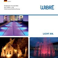
Installation · <strong>Manual</strong>Edelstahlwandstainless steel wallmur en acierKlebe-/Folienanstrichadhesive/foil coatingrevêtement collé/linerKlebeflansch/adhesive flangeflasque de collage40 mmdruckdicht geschweißtpressure welded/soudé36 mmmax 25 mmFliesen/tiles/carreaux3.3 Mörtel/mortar/mortier3.5Betonconcrete/béton3.1MörtelmortarmortierFliesentilescarreauxBeton/Estrichconcrete/floorbétonFliesentilescarreauxMörtelmortarmortier36 mmmax 25 mmBetonconcrete/béton3.23.4 3.63. Installation/MontageZur Installation sind die nationalen Sicherheitsvorschriften zubeachten. Es wird keine Haftung für unsachgemäßen Einsatz oderMontage übernommen. Bei nachträglichen Änderungen an denLeuchten wird keine Haftung übernommen.POW-LED Leuchten müssen immer in Reihenschaltung an entsprechendenKonstantstromnetzteilen oder RGB Controlern (sieheBetriebsgeräte) betrieben werden (350 mA).Die Leuchtengehäuse sind nicht zu demontieren, da zum SchutzKabel und POW LED Platine gekapselt ist.Montage des Scheinwerfers in Verbindung mit entsprechendemEinbaugehäuse in Betonbecken mit Fliesenauskleidung (max. 25 mmFliesen-/Mörtelaufbau), Edelstahlbecken (Schweißflansch), Beckenmit Klebe-/Folienanstrich (Klebeflansch) und Betoneinbau imFußbodenbereich (ohne Schalungsflansch) möglich.3. Installation/MountingWhen installing, observe the national safety regulations. We are not liablefor any improper use or installation. No liability will be accepted in case ofsubsequent modification to the lights.POW-LED lights must always be operated in series with appropriateconstant-current power sources or RGB controllers (see operating devices)(350 mA/700 mA).The light housings must not be removed, since the cable and POW LEDprinted circuit board are encapsulated for protection.Installation of the spotlight in combination with the correspondinginstallation housing in concrete pools with tile covering (max. 25 mmtile/mortar thickness), stainless steel pools (welded flange), pools withadhesive/foil coatings (adhesive flange) and concrete installation in thefloor area (without sheathing flange) possible.3. Installation/MontageRespecter les prescriptions nationales applicables en matière de sécurité.Nous déclinons toute responsabilité pour l’utilisation ou le montage non conforme.De même, nous réfutons toute responsabilité pour les modificationsréalisées sur les projecteurs.Pour leur exploitation, les projecteurs à POW-LED doivent toujours être reliésen série au bloc d‘alimentation en courant continu correspondant ou auxcontrôleurs RVB (voir blocs d‘alimentation) (350 mA/700 mA).Ne pas démonter les boîtiers du projecteur, étant donné que le câble et laplatine POW LED sont scellés.Montage du projecteur en association avec le boîtier de montage correspondantpossible dans des bassins en béton carrelé (hauteur max. carreaux/mortier 25 mm), des bassins en acier inoxydable (flasque de soudure), desbassins à revêtement collé/liner (flasque de collage) et en encastrement dansles fonds en béton (sans flasque de coffrage).Montage in BetonbeckenEinbaugehäuse mit den beiliegenden V4A-Edelstahlnägeln anvorderen Verschalung (Wasserseite) ausrichten und fixieren. Gegebenenfallsäusseren Rand z.B. mit Silikon abdichten. Kunststoffabschlussstückan der hinteren Verschalung fixieren. Einbaugehäuse,Kabelschutzrohr mit Schellen und Kunststoffabschlussstück auffesten Halt prüfen. 3.1/3.2Nach Entfernen der Verschalung Mörtel und Fliesen bis zumInnendurchmesser (36 mm) des Einbaugehäuses auftragen.Maximaler Mörtel- und Fliesenaufbau 25 mm. Bei höherem AufbauSondereinbaugehäuse auf Anfrage.Montage in EdelstahlbeckenPositionierung der Leuchten festlegen und Öffnungen von ø 40 mmin Schwimmbeckenwand ausschneiden. Einbaugehäuse ausrichtenund fixieren. Kunststoffabschlussstück am Ende des Kabelschutzrohresfixieren. Einbaugehäuse, Kabelschutzrohr mit Schellen undKunststoffabschlussstück auf festen Halt prüfen. 3.3Gehäuse mit der Schwimmbadwand druckdicht schweißen und dieSchweißnaht nachträglich passivieren.Montage in Becken mit Klebe-/FolienanstrichEinbaugehäuse mit zusätzlichem Klebeflansch mit den beiliegendenV4A-Edelstahlnägeln an vorderen Verschalung (Wasserseite) ausrichtenund fixieren. Gegebenenfalls äusseren Rand z.B. mit Silikonabdichten. Kunststoffabschlussstück an der hinteren Verschalungfixieren. Einbaugehäuse, Kabelschutzrohr mit Schellen und Kunststoffabschlussstückauf festen Halt prüfen. 3.42/4Installation in concrete poolsAlign and fasten installation housing to the front cover (water-side) usingthe accompanying V4A stainless steel nails. If necessary, seal the outeredge, for example with silicone. Fasten plastic end piece to the rear cover.Check installation housing, cable protection tube with clamps and plasticend piece for firm hold. 3.1/3.2After removal of the cover, apply mortar and tiles to no more than theinside diameter (36 mm) of the installation housing. Mortar and tilethickness 25 mm. In case of a greater thickness, a special installationhousing is available on request.Installation in stainless steel poolsDetermine positioning of the lights and cut out openings of ø 40 mm inthe swimming pool wall. Align and fasten installation housing. Fastenplastic end piece at the end of the cable protection tube. Check installationhousing, cable protection tube with clamps and plastic end piece for firmhold. 3.3Weld housing to the swimming pool wall pressure welded and thenpassivate the welding seam.Installation in poolswith adhesive/foil coatingAlign and fasten installation housing with additional adhesive flange to thefront cover (water-side) using the accompanying V4A stainless steel nails.If necessary, seal the outer edge, for example with silicone. Fasten plasticend piece to the rear cover. Check installation housing, cable protectiontube with clamps and plastic end piece for firm hold. 3.4Montage dans les bassins en bétonPositionner et fixer le boîtier d‘encastrement à l‘aide des clous en acier inoxy dableV4A fournis sur le coffrage avant (côté eau). Le cas échéant, étanchéifier le bordextérieur avec du silicone, par exemple. Fixer l‘embout d‘extrémité en plastiqueau coffrage postérieur. Vérifier la bonne fixation du boîtier d‘encas trement,de la gaine de protection du câble avec colliers et de l‘embout d‘extrémité enplastique 3.1/3.2. Après avoir retiré le coffrage, appliquer le mortier et poserles carreaux au jusqu‘au diamètre intérieur (36 mm) du boîtier d‘encastrement.Hauteur maximale mortier et carreau 25 mm. Pour les hauteurs plus élevées, desboîtiers d‘encastrement spéciaux sont disponibles sur demande.Montage dans les bassins en acier inoxydableDéterminer la position des projecteurs et découper une ouvertured‘un diamètre de 40 mm dans le bassin. Positionner et fixer le boîtierd‘encastrement. Fixer l‘embout d‘extrémité en plastique à l‘extrémitéde la gaine de protection du câble. Vérifier la bonne fixation du boîtierd‘encastrement, de la gaine de protection du câble avec colliers et de l‘emboutd‘extrémité en plastique. 3.3Souder le boîtier sur la paroi du bassin de manière à assurer l‘étanchéité puisre-passiver le cordon de soudure.Montage dans les bassins a. revêtement collé/linerPositionner et fixer le boîtier d‘encastrement avec le à l‘aide des clous enacier inoxydable V4A fournis sur le coffrage avant (côté eau). Le cas échéant,étanchéifier le bord extérieur avec du silicone, par exemple. Fixer l‘emboutd‘extrémité en plastique au coffrage postérieur. Vérifier la bonne fixation duboîtier d‘encastrement, de la gaine de protection du câble avec colliers et del‘embout d‘extrémité en plastique. 3.4WIBRE Elektrogeräte Edmund Breuninger GmbH & Co. KG · Liebigstrasse 9 · 74211 Leingarten/GermanyTelefon: +49 (0) 7131 9053-0 · Telefax: +49 (0) 7131 9053-19 · E-Mail: info@wibre.de
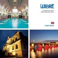
Installation · <strong>Manual</strong>3.7 3.9 3.101 POW-LED 350 mA12MAX+–braunblau+sec–NetzteilBallastAlimentationHinweis: Reihenverschaltung bauseitsReference: Serial connection made on siteRéférence: connexion en série a faire sur placeprimsec1 POW-LED RGB Multichip 350 mAprimsecCH 1CH 2CH 3+–+–+–braun/brown/brunblau/blue/bleu1max 100 mmax 100 m3.8 3.82MAXNach Entfernen der Verschalung Klebe-/Folienanstrich bis Innenkantedes Einbaugehäuses auftragen. Gegebenenfalls muß derKlebeflansch zur Haftverbesserung vorbehandelt werden. Dies ist derGebrauchsanleitung des Folienherstellers zu entnehmen. 3.5After removal of the cover, apply adhesive/foil coating up to the insideedge of the installation housing. It may be necessary to pretreat theadhesive flange for improved adhesion. This can be taken from the foilmanufacturer‘s instructions for use. 3.5Après avoir retiré le coffrage, poser le revêtement collé/liner jusqu‘au bordintérieur du boîtier d‘encastrement. Le cas échéant, le flasque de collage devraêtre prétraité afin d‘améliorer l‘adhésion. Vous trouverez ces informationsdans la notice d‘utilisation du fabricant du liner. 3.5Montage im FussbodenbereichEinbaugehäuse im Fussbodenbereich mittels Fundament oderSchrauben auf spätere Höhe des Endbelages z.B. Fliesen ausrichtenund fixieren. Der obere Rand des Einbaugehäuses sollte unbedingtdem späteren Niveau des Fussbodenbelages entsprechen und kannals Stoßkante für Fliesen oder Estriche verwendet werden.Kabelschutzrohr im Estrich verlegen und Kunststoffabschlussstückzugänglich den baulichen Gegebenheiten verlegen und Fußbodenarbeitenabschließen. 3.6Montage des ScheinwerfersDas Silikonkabel durch das Einbaugehäuse in das Kabelschutzrohreinfügen und ca 20–40 cm Kabel im Einbaugehäuse einwickeln.Am Kunststoffabschlussstück beiliegende KunststoffverschraubungM20 einschrauben und Überwurfmutter festziehen, damit das Kabelabgedichtet wird. 3.7Achtung: Nur werkseitig angeschlossenes Kabel verwenden.Gewünschte Kabellänge bei Bestellung angeben, da ein spätererAnschluss direkt an der Leuchte nicht möglich ist.Einzelanschlussader entsprechend den Vorschriften an denNetzteilen elektrisch anschließen 3.8. Die maximale Anzahl vonLeuchten und Anschlußart siehe auch Installationsanleitung desentsprechenden Netzteiles.Die Leuchte in die Einbauhülse einschieben und bis auf OberkanteAbschlussfläche eindrücken. Gegebenenfalls können die beiliegenden O-Ringe entsprechend der Aufbauhöhe ausgetauscht werden. 3.9, 3.104. Anschluß an NetzteileScheinwerfer mit POW-LED sind nur in Reihe anzuschließen. 3.8Gegebenenfalls Reihenanschluß in separater Verteilerbox vornehmen,die im Aussenbereich zusätzlich mit Vergußmasse gegenFeuchtigkeit zu schützen ist.Installation in the floor areaAlign and fasten installation housing in the floor area by means of thefoundation or screws at the later height of the final surface, e.g. tiles. Theupper edge of the installation housing should definitely be at the finallevel of the floor surface and can be used as a joint edge for the tiles orcement surface.Lay cable protection tube in the cement and lay the plastic end piece so it isaccessible to the construction situation and finish the floor work. 3.6Installation of the spotlightInsert the silicone cable through the installation housing into the cableprotection tube and wrap about 20–40 cm of cable in the installationhousing. Screw the accompanying M20 plastic screw onto the plastic endpiece and tighten the lock nut so that the cable is sealed. 3.7Attention: Use only cable connected at the factory. Specify desiredcable length when ordering, since a later connection directly to the light isno longer possible.Electrically connect individual wires to the power supply according toregulations 3.8. Also see the installation instructions of the correspondingpower supply for the maximum number of lights and type of connection.Push the light into the installation sleeve and press down until it is flushwith the top layer surface. If necessary, the accompanying O-rings can bereplaced depending on the installation height. 3.9, 3.104. Relamping and MaintenanceSpotlights with POW-LED may only be connected in series 3.8. Ifnecessary. make the serial connection in a separatedistribution box, whichoutside must also be protected against moisture with sealing compound.Montage dans le fondPositionner et fixer le boîtier d‘encastrement dans le fond à l‘aide desfondations et de vis à la hauteur finale du revêtement, par ex. les carreaux. Lebord supérieur du boîtier d‘encastrement doit impérativement être à niveauavec le revêtement de sol et peut être utilisé comme rebord de pose descarreaux ou de la chape.Poser la gaine de protection du câble dans la chape et l‘embout d‘extrémité en,fonction des conditions de construction et achever les travaux de pose du sol. 3.6Montage du projecteurInjecter le silicone à travers le boîtier d‘encastrement dans la gaine deprotection du câble et enrouler env. 20–40 cm de câble dans le boîtierd‘encastrement. Visser le raccord à vis M20 fourni au niveau de l‘emboutd‘extrémité et serrer l‘écrou-raccord afin d‘étanchéifier le câble. 3.7Attention: utiliser uniquement les câbles raccordés en usine. Indiquerla longueur souhaitée du câble lors de la commande, étant donné qu‘unraccordement ultérieur directement au projecteur ne sera pas possible.Raccorder les différents conducteurs aux blocs d‘alimentation conformémentaux prescriptions 3.8. Pour le nombre maximal de projecteurs et letype de raccordement, voir la notice d‘installation du bloc d‘alimentationcorrespondant.Insérer le projecteur dans son logement et enfoncer jusqu‘à affleurer le bordsupérieur de la surface finie.Le cas échéant, les joints toriques fournis peuvent être remplacés pourcorrespondre à la hauteur du revêtement. 3.9, 3.104.Raccordement aux blocs d‘alimentation/Matrice de raccordementLes projecteurs à POW-LED doivent uniquement être raccordés en série 3.8.Le cas échéant, procéder au raccordement en série dans des boîtiersrépartiteurs dont l‘extérieur doit être protégé contre l‘humidité à l‘aide d‘unemasse de scellement.WIBRE Elektrogeräte Edmund Breuninger GmbH & Co. KG · Liebigstrasse 9 · 74211 Leingarten/GermanyTelefon: +49 (0) 7131 9053-0 · Telefax: +49 (0) 7131 9053-19 · E-Mail: info@wibre.de 3/4
Installation · <strong>Manual</strong>5. Allgemeine Wartungshinweise- Beim Reinigen darf die Leuchte nicht mit Metall angreifenden Reinigungsmittelnin Berührung kommen. Der Einsatz salzsäurehaltigerReinigungsmittel an und in der Nähe von Scheinwerferteilenaus Edelstahl ist in jedem Fall zu unterlassen.- Achtung: Keine Hochdruckreiniger verwenden.- Achtung: Strahler vor Einfrieren schützen, gegebenenfallsmüssen diese demontiert oder speziell geschützt werden.- Verloren gegangene Schrauben dürfen nur durch Schrauben ausV4A ersetzt werden.- Je nach Beanspruchung (Höhe der Watttage, äußere Umstände)ist alle 5–8 Jahre ein Wechsel der Dichtungen (an Glasscheibe,Verschraubung, O-Ring) und der Kabel zu empfehlen.6. GarantiebestimmungenFolgende Garantiezeiten und Bestimmungen gelten vom Tage derLieferung an:- 24 Monate auf WIBRE-Scheinwerfer.- Von den Garantieansprüchen ausgenommen sind Leuchtmittel- Unter die Garantie fallen nachweisbare Material-, KonstruktionsundVerarbeitungsfehler vonseiten des Herstellers.- Für Schäden, welche durch Nichtbeachtung dieser Betriebsanleitung,oder durch unsachgemäße Reparatur entstehen, können wirkeine Garantie übernehmen.- Keine Garantie besteht, wenn die Installation nicht korrekt nachden Bestimmungen vorgenommen wurde oder bei Verwendungnicht geeigneter Leuchtmittel bzw. Anschlusskabel.- Änderungen, die dem technischen Fortschritt dienen, behaltenwir uns vor.5. General Maintenance indicationsWhen cleaning, make sure that the lights do not come into contact withmetal-corroding cleaning agents. The use of cleaning agents containinghydrochloric acid on and near spotlight parts made of stainless steel mustalways be avoided.- Attention: Do not use high-pressure cleaners.- Attention: Protect lightbulbs from freezing; they must be removed, ifnecessary, or specially protected.- Lost screws may only be replaced by screws made of V4A.- Depending on load (wattage, external conditions), we recommendchanging the seals (on the glass pane, screws, O-ring) and cable every5–8 years.6. Warranty conditionsThe following warranty periods and conditions apply from the day ofdelivery:- 24 months on WIBRE spotlights.- Lamps are excluded from warranty claims.- The warranty covers verifiable material, design and work errors by themanufacturer.- We cannot accept liability for damages caused by failure to comply withthis operating manual or through improper repair.- The warranty is void if the installation was not performed properlyaccording to the instructions or unsuitable lamps or connecting cablesare used.- We reserve the right to make changes for the purpose of technicalprogress.5. Instructions d‘entretien générales- Lors du nettoyage, le projecteur ne doit pas entrer en contact avecdétergents agressifs contre les métaux. L‘utilisation de détergent à based‘acide chlorhydrique sur et à proximité des pièces du projecteur en acierinoxydable est totalement interdite.- Attention: Ne pas utiliser de nettoyeur haute pression.- Attention: Protéger les projecteurs contre le gel; le cas échéant, les démonterou assurer une protection spéciale.- Les vis perdues ne doivent être remplacées que par des vis en acier inoxydable V4A.- Selon la sollicitation (puissance, circonstances environnementales), il estrecommandé de procéder au changement des joints (sur les vitres, lesraccords vissés et les joints toriques) du câble tous les 5 à 8 ans.6. Conditions de garantieLes délais et dispositions de garantie suivantes s‘appliquent à compter de ladate de livraison:- 24mois sur le projecteur WIBRE.- Sont exclus des conditions de garantie les ampoules.- La garantie couvre les défauts de matériaux, les vices de construction et detraitement dont la preuve est apportée qu‘ils sont imputables au fabricant.- Les dommages, résultant du non-respect de la présente notice d‘utilisationou d‘une réparation non conforme, sont exclus de la garantie.- Nous déclinons toute garantie dans les cas où l‘installation n‘a pas étéeffectuée dans les règles de l‘art selon les instructions ou lors de l‘utilisationd‘ampoules ou de câbles de raccordement non appropriés.- Nous nous réservons le droit de réaliser toute modification répondant auprogrès technique.Artikelnummerrunde BlendeArticle numbercircular coverArtikelnummerquadratische BlendeArticle numbersquared coverLeuchtmittelLampsSourceLichfarbeLight colourLumière-couleurLeistung (TLF)Wattage (TLF)Puissance (TLF)Spannung/StromTensionTensionAustrahlwinkelRadation angleAngle de rayonVersionen: Nur Unterwasserbetrieb · Versions: Only underwater operation · Versions: Fonctionnement uniquement sous l‘eau<strong>4.0012</strong>.20.11 <strong>4.0012</strong>.40.11 1 POW-LED cold white 6.000K total 2 W (140 lm) 350 mA 10° spot<strong>4.0012</strong>.20.12 <strong>4.0012</strong>.40.12 1 POW-LED warm white 3.000K total 2 W (110 lm) 350 mA 10° spot<strong>4.0012</strong>.20.13 <strong>4.0012</strong>.40.13 1 POW-LED neutral white 4.500K total 2 W (125 lm) 350 mA 10° spot<strong>4.0012</strong>.20.16 <strong>4.0012</strong>.40.16 1 POW-LED blue total 2 W (400 mW) 350 mA 10° spot<strong>4.0012</strong>.20.19 <strong>4.0012</strong>.40.19 1 Multichip POW-LED RGB all on 5 W 350 mA 120°Einbaugehäuse · installation housing · boîtier d’encastrementaus V4A-Edelstahl mit 1,5m Kabelschutzschlauch und Abschlussstutzen M20 Kunststoff, für Einbau in Betonbecken mit Fliesenauskleidung<strong>4.0012</strong>.01.00made of V4A stainless steel with 1.5 m protective cable tube and M20 plastic terminating connection, for installation in concrete pools with tile coveringen acier inoxydable V4A avec gaine de protection du câble de 1,5 m et embouts d‘extrémité M20 en plastique, pour le montage dans les bassins en béton carrelé<strong>4.0012</strong>.03.00<strong>4.0012</strong>.04.00<strong>4.0012</strong>.10.004/4aus V4A-Edelstahl mit 1,5 m Kabelschutzschlauch und Abschlussstutzen M20 Kunststoff, für Einbau in Becken mit Klebe-/Folienanstrich (Klebeflansch) AD 150 mmmade of V4A stainless steel with 1.5 m protective cable tube and M20 plastic terminating connection, for installation in pools with adhesive/foil coating (adhesive flange) AD 150 mmen acier inoxydable V4A avec gaine de protection du câble de 1,5 m et embouts d‘extrémité M20 enplastique, pour le montage dans les bassins à revêtement collé/liner (flasque de collage) DE 150 mmaus V4A-Edelstahl mit 1,5 m Kabelschutzschlauch und Abschlussstutzen M20 Kunststoff, zum Einschweißen in Edelstahlbecken (Schweißflansch)made of V4A stainless steel with 1.5 m protective cable tube and M20 plastic terminating connection, for welding into stainless steel pools (welded flange)en acier inoxydable V4A avec gaine de protection du câble de 1,5 m et embouts d‘extrémité M20 enplastique, pour le soudage dans les bassins en acier inoxydable (flasque de soudure)aus V4A-Edelstahl mit 1,5 m Kabelschutzschlauch und Abschlussstutzen M20 Kunststoff, zum Einbau im Fußbodenbereich (ohne Schalungsflansch) bei einer Aufbauhöhe des Einbaugehäuses von max. 80 mmmade of V4A stainless steel with 1.5 m protective cable tube and M20 plastic terminating connection, for installation in the floor area (without sheathing flange) with a housing installation height of max. 80 mmen acier inoxydable V4A avec gaine de protection du câble de 1,5 m et embouts d‘extrémité M20 enplastique, pour le montage dans le fond (sans flasque de coffrage) à la hauteur du revêtement du boîtier d‘encastrement de max. 80 mmZusatznummer für Sole-Version (für Solekonzentration bis 3,5 % geeignet) – Nur in Verbindung mit Scheinwerfer bestellbar.Additional number for saline-version (saltwater concentration suitable up to 3,5%) can be ordered only together with spotlightNuméro supplémentaire pour version eau salée (concentration saline élévée jusqu‘à 3,5%) - peut être commandé seulement avec projecteur9.0012.00.739.0012.01.73Scheinwerfer <strong>4.0012</strong> für Soletauglichkeit veredeln - (Bsp. <strong>4.0012</strong>.20.11 + 9.0012.00.73 = Scheinwerfer für Solewasser geeignet)Refine spotlight <strong>4.0012</strong> as saline-version - (e.g. <strong>4.0012</strong>.20.11 + 9.0012.00.73 = spotlight is suitable for saltwater concentration)Transformer projecteur <strong>4.0012</strong> en version eau salée - (p.e. <strong>4.0012</strong>.20.11 + 9.0012.00.73 = projecteur est applicable pour eau salée)Einbaugehäuse <strong>4.0012</strong> für Soletauglichkeit veredeln - (Bsp. <strong>4.0012</strong>.01.00 + 9.0012.01.73 = Einbaugehäuse für Solewasser geeignet)Refine installation housing <strong>4.0012</strong> as saline-version - (e.g. <strong>4.0012</strong>.01.00 + 9.0012.01.73 = installation housing is suitable for saltwater concentration)Transformer boîtier d‘encastrement <strong>4.0012</strong> en version eau salée - (p.e. <strong>4.0012</strong>.01.00 + 9.0012.01.73 = boîtier d‘encastrement est applicable pour eau salée)Betriebsgeräte · Power supply · Alimentation5.0635.65.03 Netzteil · Power supply · Alimentation – max. 3 POW-LED 350 mA, IP655.0635.65.10 Netzteil · Power supply · Alimentation – max. 6 POW-LED 350 mA, IP655.0635.09.16 RGB-Controler · RGB-Controler · Contrôler RGB – max. 12 POW-LED RGB, 350 mA, IP655.0635.09.24 RGB-Controler · RGB-Controler · Contrôler RGB – max. 24 POW-LED RGB, 350 mA, IP65WIBRE Elektrogeräte Edmund Breuninger GmbH & Co. KG · Liebigstrasse 9 · 74211 Leingarten/GermanyTelefon: +49 (0) 7131 9053-0 · Telefax: +49 (0) 7131 9053-19 · E-Mail: info@wibre.deW244i05 Stand 12.13 - Technische Änderungen vorbehalten - Für Druckfehler übernehmen wir keine Haftung