D GB F NL I E
D GB F NL I E
D GB F NL I E
- No tags were found...

Create successful ePaper yourself
Turn your PDF publications into a flip-book with our unique Google optimized e-Paper software.
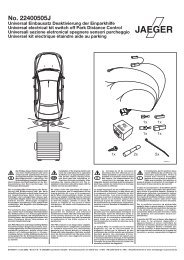
Detailed Information -Electrical Installation Set - Type 210 Saloon and Estate (T)7 8a/b7A37 Pneumatic control unitTake the pneumatic control unit (A37) out of thefoam plastic covering.Clip the brown/white wire (c) (for vehicles up to 02/97) into the free cavity 2 of the 12-pin coupling onthe pneumatic control unit.For vehicles after 03/97 in the free chamber 15 ofthe 18-pin coupling.If occupied: solder the brown/white wire to the wireavailable and insulate the connection.8aFeed in terminal 30 at the rear fuse box F4:– Remove fuses 10 to 18 from the rear fuse box F4– If there is no fuse box fitted, use the fuse boxenclosed with the electrical installation set.– If there is no power at fuse 12 of fuse box F4,insert the connector of the red auxiliary wire 25into slot 12, assignment E.8bThen connect the ring-shaped terminal end of the redauxiliary wire 25 to the positive terminal of thebattery.Note: not applicable is power is available.Connect the red wire of the towing attachmentwiring harness to slot 12, assignment D.Insert a 25 A fuse in slot 12 of the rear fuse box F4.313 116 391 102 24/0224