Extra 300 S Anleitung 130327.indd - Multiplex
Extra 300 S Anleitung 130327.indd - Multiplex
Extra 300 S Anleitung 130327.indd - Multiplex
- No tags were found...

Create successful ePaper yourself
Turn your PDF publications into a flip-book with our unique Google optimized e-Paper software.
# 26 4285DGBFIESBauanleitung 2 ... 7Building instructions 8 ... 13Notice de construction 14 ... 23Instruzioni di montaggio 24 ... 29Instrucciones de montaje 30 ... 35AbbildungenIllustrationsIllustrationsIllnstrazioniIiustraciónes... 19-22ErsatzteileReplacement partsPièces de rechangesParti di ricambioRepuestos36-39© Copyright by MULTIPLEX Modellsport GmbH & Co. KG 2013 Version 1.0
Sicherheitshinweise für MULTIPLEX-FlugmodelleDas Modell ist KEIN SPIELZEUG im üblichen Sinne.DMit Inbetriebnahme des Modells erklärt der Betreiber, dass er den Inhalt der Betriebsanleitung, besonders zu Sicherheitshinweisen,Wartungsarbeiten, Betriebsbeschränkungen und Mängel kennt und inhaltlich nachvollziehen kann.Dieses Modell darf nicht von Kindern unter 14 Jahren betrieben werden. Betreiben Minderjährige das Modell unter derAufsicht eines, im Sinne des Gesetzes, fürsorgepflichtigen und sachkundigen Erwachsenen, ist dieser für die Umsetzungder Hinweise der BETRIEBSANLEITUNG verantwortlich.DAS MODELL UND DAZUGEHÖRIGES ZUBEHÖR MUSS VON KINDERN UNTER 3 JAHREN FERNGEHALTENWERDEN! ABNEHMBARE KLEINTEILE DES MODELLS KÖNNEN VON KINDERN UNTER 3 JAHREN VERSCHLUCKTWERDEN. ERSTICKUNGSGEFAHR!Beim Betrieb des Modells müssen alle Warnhinweise der BETRIEBSANLEITUNG beachtet werden. Die <strong>Multiplex</strong> ModellsportGmbH & Co. KG ist nicht haftungspflichtig für Verluste und Beschädigungen jeder Art, die als Folge falschenBetriebes oder Missbrauches dieses Produktes, einschließlich der dazu benötigten Zubehörteile entstehen. Dies beinhaltetdirekte, indirekte, beabsichtigte und unabsichtliche Verluste und Beschädigungen und jede Form von Folge-schäden.Jeder Sicherheitshinweis dieser <strong>Anleitung</strong> muss unbedingt befolgt werden und trägt unmittelbar zum sicheren BetriebIhres Modells bei. Benutzen Sie Ihr Modell mit Verstand und Vorsicht, und es wird Ihnen und Ihren Zuschauern vielSpaß bereiten, ohne eine Gefahr darzustellen. Wenn Sie Ihr Modell nicht verantwortungsbewusst betreiben, kann dieszu erheblichen Sachbeschädigungen und schwerwiegenden Verletzungen führen. Sie alleine sind dafür verantwortlich,dass die Betriebsanleitungen befolgt und die Sicherheitshinweise in die Tat umgesetzt werden.Bestimmungsgemäße VerwendungDas Modell darf ausschließlich im Hobbybereich verwendet werden. Jede weitere Verwendung darüber hinaus ist nichterlaubt. Für Schäden oder Verletzungen an Menschen und Tieren aller Art haftet ausschließlich der Betreiber des Modellsund nicht der Hersteller.Zum Betrieb des Modells darf nur das von uns empfohlene Zubehör verwendet werden. Die empfohlenen Komponentensind erprobt und auf eine sichere Funktion passend zum Modell abgestimmt. Werden andere Komponenten verwendetoder das Modell verändert, erlöschen alle Ansprüche an den Hersteller bzw. den Vertreiber.Um das Risiko beim Betrieb des Modells möglichst gering zu halten, beachten Sie folgende Punkte:• Das Modell wird über eine Funkfernsteuerung gelenkt. Keine Funkfernsteuerung ist sicher vor Funkstörungen.Solche Störungen können dazu führen, dass Sie zeitweise die Kontrolle über Ihr Modell verlieren. Deshalb müssenSie beim Betrieb Ihres Modells zur Vermeidung von Kollisionen immer auf große Sicherheitsräume in allenRichtungen achten. Schon beim kleinsten Anzeichen von Funkstörungen müssen Sie den Betrieb Ihres Modellseinstellen!• Sie dürfen Ihr Modell erst in Betrieb nehmen, nachdem Sie einen kompletten Funktionstest und einen Reichweitentest,gemäß der <strong>Anleitung</strong> Ihrer Fernsteuerung, erfolgreich ausgeführt haben.• Das Modell darf nur bei guten Sichtverhältnissen gefl ogen werden. Fliegen Sie nicht in Richtung Sonne, umnicht geblendet zu werden, oder bei anderen schwierigen Lichtverhältnissen.• Ein Modell darf nicht unter Alkohol-Einfluss oder Einfluss von anderen Rauschmitteln oder Medikamenten betriebenwerden, die das Wahrnehmungs- und Reaktionsvermögen beeinträchtigen.• Fliegen Sie nur bei Wind- und Wetterverhältnissen, bei denen Sie das Modell sicher beherrschen können. BerücksichtigenSie auch bei schwachem Wind, dass sich Wirbel an Objekten bilden, die auf das Modell Einfl ussnehmen können.• Fliegen Sie nie an Orten, an denen Sie andere oder sich selbst gefährden können, wie z.B. Wohngebiete, Überlandleitungen,Straßen und Bahngleise.• Niemals auf Personen und Tiere zufliegen. Anderen Leuten dicht über die Köpfe zu fliegen ist kein Zeichen fürwirkliches Können, sondern setzt andere Leute nur ein unnötiges Risiko aus. Weisen Sie auch andere Pilotenin unser aller Interesse auf diese Tatsache hin. Fliegen Sie immer so, dass weder Sie noch andere in Gefahrkommen. Denken Sie immer daran, dass auch die allerbeste Fernsteuerung jederzeit gestört werden kann. Auchlangjährige, unfallfreie Flugpraxis ist keine Garantie für die nächste Flugminute.Seite 2
DRestrisikenAuch wenn das Modell vorschriftsmäßig und unter Beachtung aller Sicherheitsaspekten betrieben wird, besteht immerein gewisses Restrisiko.Eine Haftpflichtversicherung ist daher obligatorisch. Falls Sie in einen Verein oder Verband eintreten, können Sie dieseVersicherung dort abschließen. Achten Sie auf ausreichenden Versicherungsschutz (Modellflugzeug mit Antrieb). HaltenSie Modelle und Fernsteuerung immer absolut in Ordnung.Folgende Gefahren können im Zusammenhang mit der Bauweise und Ausführung des Modells auftreten:• Verletzungen durch die Luftschraube: Sobald der Akku angeschlossen ist, ist der Bereich um die Luftschraubefreizuhalten. Beachten Sie auch, dass Gegenstände vor der Luftschraube angesaugt werden können oder Gegenständedahinter weggeblasen werden können. Das Modell kann sich in Bewegung setzen. Richten Sie esdaher immer so aus, dass es sich im Falle eines ungewollten Anlaufen des Motors nicht in Richtung andererPersonen bewegen kann. Bei Einstellarbeiten, bei denen der Motor läuft oder anlaufen kann, muss das Modellstets von einem Helfer sicher festgehalten werden.• Absturz durch Steuerfehler: Kann dem besten Piloten passieren, deshalb nur in sicherer Umgebung fliegen; einzugelassenes Modellfl uggelände und eine entsprechende Versicherung sind unabdingbar.• Absturz durch technisches Versagen oder unentdeckten Transport- oder Vorschaden. Die sorgfältige Überprüfungdes Modells vor jedem Flug ist ein Muss. Es muss jedoch immer damit gerechnet werden, dass es zu Materialversagenkommen kann. Niemals an Orten fliegen, an denen man Anderen Schaden zufügen kann.• Betriebsgrenzen einhalten. Übermäßig hartes Fliegen schwächt die Struktur und kann entweder zu plötzlichemMaterialversagen führen, oder bei späteren Flügen das Modell aufgrund von „schleichenden“ Folgeschädenabstürzen lassen.• Feuergefahr durch Fehlfunktion der Elektronik. Akkus sicher aufbewahren, Sicherheitshinweise der Elektronikkomponentenim Modell, des Akkus und des Ladegerätes beachten, Elektronik vor Wasser schützen. Aufausreichende Kühlung bei Regler und Akku achten.Die <strong>Anleitung</strong>en unserer Produkte dürfen nicht ohne ausdrückliche Erlaubnis der <strong>Multiplex</strong> Modellsport GmbH& Co. KG (in schriftlicher Form) - auch nicht auszugsweise in Print- oder elektronischen Medien reproduziertund / oder veröffentlicht werden.Seite 3
Machen Sie sich mit dem Bausatz vertraut!MULTIPLEX – Modellbaukästen unterliegen während der Produktion einer ständigen Materialkontrolle. Wir hoffen, dassSie mit dem Baukasteninhalt zufrieden sind. Wir bitten Sie jedoch, alle Teile (nach Stückliste) vor Verwendung zu prüfen,da bearbeitete Teile vom Umtausch ausgeschlossen sind. Sollte ein Bauteil einmal nicht in Ordnung sein, sindwir nach Überprüfung gern zur Nachbesserung oder zum Umtausch bereit. Bitte senden Sie das Teil, bitte ausreichendfrankiert, an unsere Modellbauabteilung und fügen Sie unbedingt den Kaufbeleg und eine kurze Fehlerbeschreibung bei.Wir arbeiten ständig an der technischen Weiterentwicklung unserer Modelle. Änderungen des Baukasteninhalts inForm, Maß, Technik, Material und Ausstattung behalten wir uns jederzeit und ohne Ankündigung vor. Bitte haben SieVerständnis dafür, dass aus Angaben und Abbildungen dieser <strong>Anleitung</strong> keine Ansprüche abgeleitet werden können.Achtung!Ferngesteuerte Modelle, insbesondere Flugmodelle, sind kein Spielzeug im üblichen Sinne. Ihr Bau und Betrieberfordert technisches Verständnis, ein Mindestmaß an handwerklicher Sorgfalt sowie Disziplin und Sicherheitsbewusstsein.Fehler und Nachlässigkeiten beim Bau und Betrieb können Personen- und Sachschäden zur Folgehaben. Da der Hersteller keinen Einfluss auf ordnungsgemäßen Zusammenbau, Wartung und Betrieb hat, weisenwir ausdrücklich auf diese Gefahren hin.Warnung:Das Modell hat, wie jedes Flugzeug, statische Grenzen! Sturzflüge und unsinnige Manöver im Unverstand können zumVerlust des Modells führen. Beachten Sie: In solchen Fällen gibt es von uns keinen Ersatz. Tasten Sie sich also vorsichtigan die Grenzen heran. Das Modell ist auf den von uns empfohlenen unseren Antrieb ausgelegt, kann aber nur einwandfreigebaut und unbeschädigt den Belastungen standhalten.Benötigtes Zubehör für das Modell <strong>Extra</strong> <strong>300</strong> S:Li-BATT FX 4/1-2600 (M6) Best.-Nr. 15 7362Empfänger RX-5 light M-LINK 2,4 GHz Best.-Nr. 5 5808DOptionales Zunehör für das <strong>Extra</strong> <strong>300</strong> S:Empfänger RX-7 M-LINK 2,4 GHz Best.-Nr. 5 5818Strom-Sensor 35 A (M6) für M-LINK Empfänger Best.-Nr. 8 5403MULTIlight, 5 LEDs Best.-Nr. 7 3020Sender COCKPIT SX Best.-Nr. 4 5130/1/2Combo MULTIcharger LN-<strong>300</strong>8 EQU mit Netzteil AC/DC 230V/12V 5,0A Best.-Nr. 9 2545Ladekabel (M6) für MULTIcharger LN-<strong>300</strong>8 EQU Best.-Nr. 9 2516Seite 4
Wichtiger HinweisDieses Modell ist nicht aus Styropor ! Daher sind Verklebungen mit Weißleim, Polyurethan oder Epoxy nicht möglich.Diese Kleber haften nur oberfl ächlich und platzen im Ernstfall einfach ab. Verwenden Sie nur Cyanacrylat-/Sekundenklebermittlerer Viskosität, vorzugsweise Zacki -ELAPOR® # 85 2727, der für ELAPOR® Partikelschaum optimierte undangepasste Sekundenkleber. Bei Verwendung von Zacki-ELAPOR® können Sie auf Kicker oder Aktivator weitgehendverzichten. Wenn Sie jedoch andere Kleber verwenden, und auf Kicker/Aktivator nicht verzichten können, sprühen Sieaus gesundheitlichen Gründen nur im Freien. Vorsicht beim Arbeiten mit allen Cyanacrylatklebern. Diese Kleber härtenu.U. in Sekunden, daher nicht mit den Fingern und anderen Körperteilen in Verbindung bringen. Zum Schutz der Augenunbedingt Schutzbrille tragen! Von Kindern fernhalten! An einigen Stellen ist es auch möglich Heißkleber zu verwenden.Wir weisen in der <strong>Anleitung</strong> ggf. darauf hin!Arbeiten mit Zacki ELAPOR®Zacki ELAPOR® wurde speziell für die Verklebung für unsere Schaummodelle aus ELAPOR® entwickelt.Um die Verklebung möglichst optimal zu gestalten, sollten Sie folgende Punkte beachten:• Vermeiden Sie den Einsatz von Aktivator. Durch ihn wird die Verbindung deutlich geschwächt.Vor allem bei großflächiger Verklebung empfehlen wir, die Teile 24 h trocken zu lassen.• Aktivator ist lediglich zum punktuellen Fixieren zu verwenden. Sprühen Sie nur wenig Aktivator einseitig auf.Lassen Sie den Aktivator ca. 30 Sekunden ablüften.• Für eine optimale Verklebung rauen Sie die Oberfläche mit einem Schleifpapier (320 er Körnung) an.Krumm - gibt es eigentlich nicht. Falls mal etwas z.B. beim Transport verbogen wurde, kann es wieder gerichtetwerden. Dabei verhält sich ELAPOR® ähnlich wie Metall. Etwas überbiegen, das Material federt ein Stück zurückund behält dann aber die Form. Alles hat natürlich auch seine Grenzen - übertreiben Sie also nicht!Krumm - gibt es schon! Wenn Sie Ihr Modell lackieren wollen, reiben Sie die Oberfläche leicht mit MPX Primer #602700 ab, so als wollten Sie das Modell putzen. Die Lackschichten dürfen keinesfalls zu dick oder ungleichmäßigaufgetragen werden, sonst verzieht sich das Modell. Es wird krumm, schwer und oft sogar unbrauchbar! Mattlackebringen optisch das beste Ergebnis.Technische Daten:Spannweite:Rumpfl änge:Fluggewicht ab:Flächenbelastung (FAI) ab:RC-Funktionen:Flugzeit:1200 mm1086 mm1450 g39 g/dm²Seitenruder, Höhenruder, Querruder, Motor,ca. 7 minHinweis: Bildseiten aus der Mitte der Bauaneitung heraustrennen!Seite 5
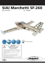
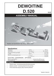
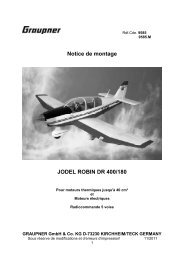
Herzlichen Glückwunsch zu Ihrer neuen <strong>Multiplex</strong> <strong>Extra</strong><strong>300</strong>-S.Die <strong>Extra</strong> <strong>300</strong> S ist im Original ein einsitziges Kunstflugzeugmit 7,5m Spannweite und wird von einem LycomingSechszylinder-Boxermotor mit <strong>300</strong> PS angetrieben. Es istein sehr beliebtes Flugzeug bei Kunstflugwettbewerben,Shows und Luftrennen.Das ELAPOR®-Modell mit seiner handlichen Größe siehtnicht nur klasse aus, sondern überzeugt auch mit einerhervorragenden Performance im Kunstfl ug.Es hat eine sehr originalgetreue Linienführung und ist mitzahlreichen Details, wie Nieten, Auspuffattrappen, einemdetaillierten Cockpit sowie einer originalgetreuen Lackierungversehen. Die <strong>Extra</strong> <strong>300</strong> S ist primär für klassischenProgrammkunstflug ausgelegt, kann aber auch im 3D bewegtwerden. Mit gerissenen und gestoßenen Figuren,sowie mit Messerfl ügen und Überschlägen werden Sieeine wahre Freude haben. Durch den 4S-Antrieb ist eineenorme Leistung für kraftvolle, senkrechte Steigfl üge vorhanden.- Super- Kunstflugeigenschaften- Scale- Optik durch Originallackierung, durchsichtigeKabinenhaube und zahlreiche Details- Alle Ruder in Hohlkehlen gelagert- Abnehmbare Flächen und Leitwerke- Flugzeit ca. 7 min (4S ~2600Ah)Zusammenbau:Zum Bau des Modells benötigen Sie folgendes Werkzeug:- Kreuzschlitzschraubendreher klein- Kreuzschlitzschraubendreher groß- Inbusschlüssel SW 1,5- Spitzzange- 13er Gabelschlüssel- Schraubensicherungslack- Zacki ElaporÜberprüfen Sie die gelieferten Teile auf Ihre Vollständigkeitmittels der Stückliste auf Seite 7.1. Befestigung des Fahrwerks:Befestigen Sie das Fahrwerk 6 mit den vier beiliegendenselbstschneidenden Kreuzschlitzschrauben 20 (3x20 mm)an der vorgesehenen Stelle am Rumpf 3 und ziehen Siediese handfest an.2. Befestigung der Leitwerke:Stecken Sie das Höhenleitwerk 7 in die Führungsschlitzeam Rumpf 3 und schrauben Sie es mit der Kreuzschlitz-Senkkopfschraube 21 (M4x42 mm) von oben handfest an(großer Kreuzschlitzschraubendreher).Verbinden Sie nun das Höhenruderservo mit dem Ruderhornder Höhenruderklappe. Bringen Sie zuerst das Servomittels Ihrer Fernsteuerung in die Neutrallage. Fädelnsie dann das Z-Gestänge 22 (1,5x135 mm) in das mittlereSeite 6Loch des Ruderhorns an der Klappe ein. Schrauben Siees mit einem Inbusschlüssel (SW 1,5) an dem am Servohornangebrachten Gestängeanschluss mit der M3x3 mmMadenschraube fest.Stecken Sie nun von oben die Seitenruder-Dämpfungsfläche8 in das Höhenleitwerk 7 und sichern Sie diese mitden beiden selbstschneidenden Kreuzschlitzschrauben23 (2,6x12 mm).Klipsen Sie das Seitenruderblatt 9 in die beiden Gegenlagerder Dämpfungsfl äche 8 ein, bis ein hörbares Klickenertönt. Verbinden Sie nun das Seitenruder mit dem Servo.Gehen Sie wie beim Höhenruder vor.Hängen Sie die Federn 24 in die dafür vorgesehenen Laschenein und schrauben Sie diese unter Verwendungvon etwas Schraubensicherungslack (Alternative: wenigZacki) am Steuerhebel des Spornrades an. Achten Siedarauf, dass das Spornrad parallel zum Seitenruderblatt9 steht.3. Motoreinbau und Motorhaube:Die Motorhaube 5 wird mit zwei Magneten am Rumpf gehalten.Entfernen Sie diese und kontrollieren Sie die Motorschraubenauf festen Sitz. Setzen Sie anschließend dieMotorhaube wieder auf.4. Befestigung der Luftschraube und des Spinners:Wuchten Sie die Luftschraube 13 vor allen weiteren Arbeitenaus. Wir empfehlen dazu unser Propeller-Wuchtgerät# 33 2355.Schieben Sie den vormontierten Propeller, bestehend ausSpannzange 16, Spannhülse 17, Spinnerrückplatte 14,Luftschraube 13, U-Scheibe 18 und Mutter 19 auf die Motorwelle.Ziehen Sie die Mutter mit einem Gabelschlüssel SW13fest an und überprüfen Sie den Rundlauf der Spinnerrückplatte,indem Sie den Propeller per Hand drehen.Geben Sie nun einen Tropfen Schraubensicherungslackan das M3 Innengewinde der Luftschraubenkupplung undsetzen Sie die Spinnerkappe 15 auf.Ziehen Sie die Zentralschraube 25 (M3x45 mm) gefühlvollfest und überprüfen Sie den Rundlauf erneut. Solltedie Spinnerkappe etwas eiern, dann lösen Sie die Zentralschraubeetwas, oder versetzen Sie die Spinnerkappeum 120° und probieren es erneut, bis der Spinner rundläuft.5. Befestigung der Flächen:Entfernen Sie den Akkudeckel 4, damit sie eine freie Sichtin den Innenraum haben.Fädeln Sie nun den CFK Holm 12 (8 mm) in eine Flächenhälfteund stecken Sie die Einheit in den Rumpf. FädelnSie das Servokabel durch die dafür vorgesehene Öffnung.Stecken Sie nun die andere Flächenhälfte an den Rumpf.
Achten Sie dabei darauf, dass die Servokabel beider Flächendurch die vorgesehene Öffnung im Rumpf liegen. FixierenSie nun die Tragflächen mit den Tragflächenschrauben26 (M4x 80) mm am Rumpf.6. Empfängereinbau:Stecken Sie die Servostecker in den Empfänger. Die Ziffernauf den Steckern haben folgende Zuordnung:1 Querruder links2 Höhenruder3 Seitenruder4 Motor5 Querruder rechtsBefestigen Sie den Empfänger mit etwas Klettband 27&28unterhalb des Instrumentenpilzes.7. Auswiegen:Schieben Sie den Antriebsakku auf der Akkurutsche so inPosition, dass der Schwerpunkt bei 90 mm liegt (gemessenan der Tragflächenvorderkante in Rumpfnähe). BefestigenSie den Akku mit den beiliegenden Klettbändern.Für eine feste Verbindung des Klettbandes am Rumpfbodenempfehlen wir ein paar Tropfen Zacki anzugeben.8. Empfohlene Ruderausschlägefür klassischen Programmkunstflug:Seitenruder: rechts / links 25 mm 50% EXPOHöhenruder: hoch / runter 15 mm 30% EXPOQuerruder: hoch 15 mm runter 10mm 30% EXPOFür 3D-Kunstflug:Seitenruder: rechts/links 25 mm 50% EXPOHöhenruder: hoch / runter 35 mm, 65% EXPOQuerruder: hoch 40mm runter 30mm, 50% EXPOStückliste <strong>Extra</strong> <strong>300</strong> S # 26 4285lfd. Nr Stück Bezeichnung Material Abmessungen1 1 Bauanleitung <strong>Extra</strong> <strong>300</strong> S Papier DIN A42 1 Reklamationsbearbeitung Papier DIN A43 1 Rumpf (fertig montiert mit Motor, Regler, HR- & SR-Servos) Fertigteil4 1 Akkudeckel Elapor Fertigteil5 1 Motorhaube Elapor Fertigteil6 1 Hauptfahrwerk (fertig montiert) Kunststoff/ Aluminium Fertigteil7 1 Höhenleitwerk (Dämpfungsfläche und Ruder fertig montiert) Fertigteil8 1 Seitenruder-Dämpfungsfläche Elapor Fertigteil9 1 Seitenruder Elapor Fertigteil10 1 Tragflächen links (fertig montiert mit QR-Servo) Fertigteil11 1 Tragfl ächen rechts (fertig montiert mit QR-Servo) Fertigteil12 1 Steckungsrohr Kohlefaser Ø 8mm/ 690mm13 1 Luftschraube Kunststoff 12x8“ 3-Blatt14 1 Spinnerrückplatte Kunststoff Ø 52 mm15 1 Spinnerkappe Kunststoff Ø 52 mm16 1 Spannzange Aluminium Ø 5 mm innen, 8 mm außen17 1 Spannhülse Aluminium Fertigteil18 1 U-Scheibe Stahl Ø 8 mm innen19 1 Mutter Stahl M820 4 Schrauben für Hauptfahrwerk (selbstschneidend), Stahl 3x20 mm21 2 Kreuzschlitz - Senkkopfschraube für Höhenleitwerk M4x42 mm22 2 Z-Gestänge Höhenruder und Seitenruder, Metall 1,5x135 mm23 2 Schrauben für Seitenleitwerk (selbstschneidend) 2,6x12 mm24 2 Federn für Spornradlenkung Metall Ø 5 mm / 60 mm25 1 Spinner-Zentralschraube Metall M3x45 mm26 2 Tragflächenschrauben Metall M4x80 mm27 2 Klettband Hakenseite Kunststoff Fertigzuschnitt28 2 Klettband Schlaufenseite Kunststoff FertigzuschnittSeite 7
Safety Information for MULTIPLEX model aircraftThis model is NOT A TOY in the usual sense of the term.GBBy operating the model the owner affi rms that he is aware of the content of the operating instructions, especially thosesections which concern safety, maintenance, operating restrictions and faults, and is capable of fulfilling these requirements.This model must not be operated by any child under fourteen years of age. If a person below this age operates the modelunder the supervision of a competent adult who is acting as the child’s guardian within the legal sense of the term, thisindividual is responsible for the implementation of the information in the OPERATING INSTRUCTIONS.THE MODEL AND ASSOCIATED ACCESSORIES MUST BE KEPT OUT OF THE REACH OF CHILDREN UNDER THREEYEARS OF AGE! MODELS CONTAIN SMALL DETACHABLE PARTS WHICH MAY BE SWALLOWED BY CHILDRENUNDER THREE YEARS. CHOKING HAZARD!All the warnings in the OPERATING INSTRUCTIONS must be observed whenever the model is operated. <strong>Multiplex</strong>Modellsport GmbH & Co. KG accepts no liability for loss or damage or any kind which occurs as a result of incorrectoperation or misuse of this product, including the accessories required for its operation. This includes direct, indirect,deliberate and accidental loss and damage, and all forms of consequent damage.Every safety note in these instructions must always be observed, as all the information contributes to the safe operationof your model. Use your model thoughtfully and cautiously, and it will give you and your spectators many hours ofpleasure without constituting a hazard. Failure to operate your model in a responsible manner may result in signifi cantproperty damage and severe personal injury. You alone bear the responsibility for the implementation of the operatinginstructions and the safety notes.Approved usageThe model is approved exclusively for use within the modelling hobby. It is prohibited to use the model for any otherpurpose than that stated. The operator of the model, and not the manufacturer, is responsible for damage or injury ofany kind resulting from non-approved use.The model may only be operated in conjunction with those accessories which we expressly recommend. The recommendedcomponents have undergone thorough testing, are an accurate match to the model, and ensure that it functionssafely. If you use other components, or modify the model, you operate it at your own risk, and any claim under guaranteeis invalidated.To minimise the risk when operating the model, please observe the following points:• The model is guided using a radio control system. No radio control system is immune to radio interference, andsuch interference may result in loss of control of the model for a period of time. To avoid collisions, you musttherefore ensure at all times that there is a wide margin of safety in all directions when operating your model. Atthe slightest sign of radio interference you must cease operating your model!• Never operate your model until you have successfully completed a thorough check of the working systems, andcarried out a range-check as stipulated in the instructions supplied with your transmitter.• The model may only be flown in conditions of good visibility. You can avoid being temporarily blinded by not flyingtowards the sun, or in other diffi cult light conditions.• A model must never be operated by a person who is under the influence of alcohol, drugs or medication whichhave an adverse effect on visual acuity and reaction time.• Only fly your model in conditions of wind and weather in which you are able to maintain full control of the model.Even when the wind is light, bear in mind that turbulence can form at and around objects which may have aneffect on the model.• Never fly in any location where you may endanger yourself of others, e.g. close to residential areas, overheadcables, open roads and railway lines.• Never fly towards people or animals. You may think that flying low over other people’s heads is proof of yourpiloting skill, but all it does is place others at unnecessary risk. It is in all our interests that you let other pilotsknow that this is what you think. Always fly in such a way that you do not endanger yourself or others. Bear inmind that even the best RC system in the world is subject to outside interference. No matter how many years ofaccident-free fl ying you have under your belt, you have no idea what will happen in the next minute.Seite 8
GBResidual risksEven if the model is operated in the correct manner, and you observe all safety aspects, there is always a certain residualrisk.For this reason it is mandatory to take out third-party liability insurance. If you join a club or flying association, insuranceis usually available or included in the annual fee. Make sure that your insurance cover is adequate (i.e. that it coverspowered model aircraft). Always keep your models and your radio control equipment in perfect order.The following hazards may occur owing to the model’s construction and type:• Injury caused by the propeller: you must keep well clear of the area around the propeller from the moment thatthe battery is connected. Please bear in mind that objects in front of the propeller may be sucked into it, andobjects behind the propeller may be blown away by it. The model may start moving when the propeller startsto turn. You must therefore position the model in such a way that it cannot move towards other persons if themotor should unexpectedly start running. When you are carrying out adjustment work involving the runningmotor, you must ensure that the model is always held securely by an assistant.• Crash caused by pilot error: this can happen even to the best of pilots, so it is essential to fly exclusively in asafe environment: an approved model flying site and suitable insurance are basic essentials.• Crash caused by technical failure or unnoticed damage in transit or in the workshop. A thorough check of themodel before every flight is essential. However, you should also take into account at all times that materialfailures can and do occur. Never fly in a location where your model may damage or injure others.• Keep within the stated operating limits. Excessively violent fl ying will weaken the airframe, and may result insudden material failure, or may cause the model to crash during a subsequent fl ight due to “creeping” consequentdamage.• Fire hazard caused by electronic failure or malfunction. Store batteries safely, and always observe safetynotes which apply to the airborne electronic components, the battery and the battery charger. Protect all electronicequipment from damp. Ensure that the speed controller and battery are adequately cooled.The instructions which accompany our products must not be reproduced and / or published, in full or in part, inprint or any electronic medium, without the express written approval of <strong>Multiplex</strong> Modellsport GmbH & Co. KG.Seite 9
Examine your kit carefully!MULTIPLEX model kits are subject to constant quality checks throughout the production process, and we sincerelyhope that you are completely satisfied with the contents of your kit. However, we would ask you to check all the partsbefore you start construction, as we cannot exchange components which you have already worked on. If you findany part is not acceptable for any reason, we will readily correct or exchange it. Just send the component to our ModelDepartment. Please be sure to include the purchase receipt and a brief description of the fault.We are constantly working on improving our models, and for this reason we must reserve the right to change the kitcontents in terms of shape or dimensions of parts, technology, materials and fittings, without prior notifi cation. Pleaseunderstand that we cannot entertain claims against us if the kit contents do not agree in every respect with the instructionsand the illustrations.Caution!Radio-controlled models, and especially model aircraft, are by no means playthings. Building and operating themsafely requires a certain level of technical competence and manual skill, together with discipline and a responsibleattitude at the flying field. Errors and carelessness in building and flying the model can result in seriouspersonal injury and damage to property. Since we, as manufacturers, have no control over the construction,maintenance and operation of our products, we are obliged to take this opportunity to point out these hazardsand to emphasise your personal responsibility.Warning:Like every aeroplane, this model has static limits. Steep dives and senseless manoeuvres inappropriate to the typemay result in the loss of the aircraft. Please note: we will not replace the model in such cases. It is your responsibility toapproach the airframe’s limits gradually. It is designed for the power system recommended in these instructions, but isonly capable of withstanding the fl ight loads if built exactly as described and if it is in an undamaged state.Recommended equipment:Li-BATT FX 4/1-2600 (M6) Item number: 15 7362Receiver RX-5 light M-LINK 2,4 GHz Item number: 5 5808Optional equipment:GBReceiver RX-7 M-LINK 2,4 GHz Item number: 5 5818Current sensor 35 A (M6) for receivers M-LINK Item number: 8 5403MULTIlight, 5 LEDs Item number: 7 3020COCKPIT SX M-LINK classic, transmitter 2,4 GHz Item number: 4 5130/1/2Combo MULTIcharger LN-<strong>300</strong>8 EQU w.Mains PSU, AC/DC 230V/12V 5,0A Item number: 9 2545Charge lead w. high current plug (M6) Item number: 9 2516Seite 10
Important noteThis model is not made of Styrofoam, and it is not possible to glue the material using white glue, polyurethane orepoxy; these adhesives only produce superfi cial joints, and simply break away under stress. Please be sure to usemedium-viscosity cyano-acrylate glue exclusively, preferably Zacki ELAPOR® # 59 2727, which is optimised specifi callyfor ELAPOR® particle foam. If you se Zacki ELAPOR® there is usually no need for cyano ‘kicker’ or activator. However,if you wish to use a different adhesive which requires the use of activator, please note that these materials are injuriousto health, and should always be applied in the open air. Take care when handling all cyano-acrylate adhesives, as theyharden in seconds, so don’t get them on your fingers or other parts of the body. We strongly recommend the use ofgoggles to protect your eyes. Keep the adhesive out of the reach of children! For certain joints it is also possible to usehot-melt adhesive; the instructions indicate where this is the case.Working with Zacki ELAPOR®Zacki ELAPOR® has been developed specifically for glued joints in our models which consist of moulded ELAPOR®foam parts.Please observe the following points in order to obtain perfect joints:• Avoid the use of activator. ‘Kicker’ significantly weakens the joint. We advise leaving joined parts for 24 hours to obtainmaximum strength, particularly when the glued area is large.• Activator should only be used for temporary, small-area joints (‘tacking’). Spray a little activator on one surface, andallow it to air-dry for about thirty seconds.• To obtain maximum joint strength you should lightly sand the surface with 320-grit abrasive paper before applying glue.Bent parts - actually don’t exist. If you find that a component has taken up a curve, perhaps after being transported,it is easy to straighten again. In this respect ELAPOR® behaves in a similar way to metal: bend thecomponent back slightly beyond the correct position, and the material will then spring back to its proper shapewhen released, and maintain it. There are limits, however - don’t overdo it!Bent parts - really do exist. If you wish to paint your model, apply MPX Primer # 60 2700 to the surfaces, wiping it onvery lightly as if you were cleaning the model. Paint must always be applied thinly and evenly, otherwise the componentwill warp. Then you really will have bent parts, and they will also be heavy and perhaps even unusable. We have foundthat matt-finish paints produce the best visual effect.Technical information <strong>Extra</strong> <strong>300</strong> S:WingspanOverall lenghAll-up weightWing loadingRC FunctionsTime of flight:1200 mm1086 mm1450 g39 g/dm²rudder, elevator, aileron, motorca. 7 minNote: please remove the pictures from the center of the instructions!Seite 11
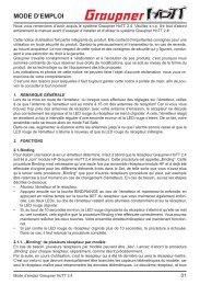
Warmest congratulations on your new <strong>Multiplex</strong> <strong>Extra</strong> <strong>300</strong>-S.The full-size <strong>Extra</strong> <strong>300</strong> S is a single-seat aerobatic aircraftwith a wingspan of 7.5 m, powered by a Lycoming sixcylinderopposed engine generating <strong>300</strong> BHP. It is a verypopular aircraft, widely fl own in aerobatic competitions,airshows and air-races.Our ELAPOR® model is of manageable size, and offersa superb aerobatic perfor-mance as well as looking great.The machine’s lines are very accurate, and it featuresnumerous details such as dummy rivets and exhausts, adetailed cockpit interior and a scale colour scheme. The<strong>Extra</strong> <strong>300</strong> S is primarily designed for the classic aerobaticschedule, but also copes very well with 3D flying. Competentpilots will thoroughly enjoy positive and negative flick-rolls,knife-edge flight and flips. The 4S power system providesenor-mous power and stunning vertical climbing ability.- Outstanding aerobatic characteristics- Scale appearance: original colour scheme, clear canopyand numerous details- All control surfaces attached with recessed “knuckle”hinge lines- Detachable wing and tail panels- Flight time approx. 7 min (4S ~2600 mAh)Assembly:You will need the following tools to complete the model:Small cross-point screwdriverLarge cross-point screwdriverAllen key, 1.5 mm A/FPointed-nose pliers13 mm A/F open-ended spannerThread-lock fl uidZacki ElaporPlease check that your kit contains all the componentsas stated in the Parts List on page 13.1. Attaching the undercarriage:Place the undercarriage 6 in the recess in the fuselage 3and secure it with the four cross-point self-tapping screws20 (3 x 20 mm). Do not over-tighten the screws.2. Attaching the tail panels:Place the tailplane 7 on the fuselage 3, engaging the guidelugs, and secure it by fitting the countersunk cross-pointscrew 21 (M4 x 42 mm) from above. Tighten the screwusing a large cross-point screwdriver; take care not toover-tighten it.The next step is to connect the elevator servo to the elevatorhorn: first use your transmitter to set the servo to centre(neutral), then thread the pre-formed end of the pushrod22 (1.5 x 135 mm) through the centre hole of the elevatorhorn. Slip the plain end of the pushrod through the barrelof the swivel connector mounted on the servo output arm,and tighten the M3 x 3 mm grubscrew using a 1.5 mm A/Fallen key.Seite 12Now insert the fin 8 in the slot in the tailplane 7 from above,and fit the two cross-point self-tapping screws 23 (2.6 x 12mm) to secure it.Engage the rudder 9 in the two hinge lugs attached to thefin 8; you should hear a distinct click. The rudder can nowbe connected to the servo, using the same procedure asdescribed for the elevator.Connect the hooked end of the springs24 to the lugs in thebottom of the rudder, then slip the plain ends through theswivel connectors on the tailwheel steering lever. Applya drop of thread-lock fluid or Zacki to prevent the screwsworking loose. Ensure that the tailwheel is parallel to therudder before tightening the screws.3. Installing the motor and cowl:The cowl 5 is held in place on the fuselage by means of twomagnets. Withdraw the cowl, and check that the motor retainingscrews are tight, then replace the cowl on the fuselage.4. Attaching the propeller and spinner:The propeller 13 must be balanced before you proceedany further.We recommend our propeller balancer, # 33 2355, for this.Prepare the propeller assembly - propeller driver 16, tapercollet 17, spinner backplate 14, propeller 13, washer 18 andnut 19 - and fi t it on the motor shaft.Tighten the propeller nut firmly using an open-ended 13 mmA/F spanner, then turn the propeller by hand to check thatthe spinner backplate is running true.Apply a drop of thread-lock fluid to the M3 internal threadof the propeller driver, and fi t the spinner cap 15.Carefully tighten the central spinner screw 25 (M3 x 45 mm),then check that the spinner still runs true. If the spinner capis out of line, try loosening the central screw slightly; alternativelyremove the spinner cap, turn it through 120° andtry again. Continue until the spinner runs absolutely true.5. Attaching the wing panels:Remove the battery hatch cover 4 to provide an unobstructedview of the interior of the fuselage.Now slide the CFRP wing joiner tube 12 (8 mm) into onewing panel, and fi t this assembly into the recess in thefuselage, threading the servo lead through the appropriateopening. Now fit the second wing panel onto the joiner tubeand into the fuselage. Check that the servo leads of bothwing panels run through the openings in the fuselage. Thetwo wing panels can now be secured against the fuselageby fi tting the wing screws 26 (M4 x 80 mm).
6. Installing the receiver:The next step is to connect the servo plugs to the receiver.This is the key to the numbered plugs:1 Left aileron2 Elevator3 Rudder4 Throttle5 Right aileronSecure the receiver below the instrument panel using smallpieces of the hook-and-loop tape 27 / 28.7. Checking the CG:Place the flight battery in the battery tray, and adjust itsposition until the model balances at the 90 mm C.G. mark(measured from the wing leading edge adjacent to thefuselage). Fix the battery in place with the hook-and-looptape supplied.We recommend applying a few drops of Zacki to the adhesiveface of the hook-and-loop tape to stick it securely tothe bottom of the fuselage.8. Recommended control surface travelsFor the classic aerobatic schedule:Rudder: 25 mm right / left 50% EXPOElevator: 15 mm up / down 30% EXPOAilerons: 15 mm up, 10 mm down 30% EXPOFor 3D aerobatics:Rudder: 25 mm right / left 50% EXPOElevator: 35 mm up /down 65% EXPOAilerons: 40 mm up, 30 mm down 50% EXPOParts List - <strong>Extra</strong> <strong>300</strong> S # 26 4285Part No. Qty Description Material Dimensions1 1 <strong>Extra</strong> <strong>300</strong> S building instructions, Paper DIN A42 1 Model complaint form Paper DIN A43 1 Fuselage (factory-assembled, with motor, ESC, elevator / rudder servos)4 1 Battery hatch cover Moulded Elapor foam Ready made5 1 Cowl Moulded Elapor foam Ready made6 1 Main undercarriage (factory-assembled) Ready made7 1 Tailplane (fixed panel and elevators, factory-assembled) Ready made8 1 Fin Moulded Elapor foam Ready made9 1 Rudder Moulded Elapor foam Ready made10 1 L.H. wing panel (factory-assembled, with aileron servo Ready made11 1 R.H. wing panel (factory-assembled, with aileron servo) Ready made12 1 Wing joiner tube CFRP tube Ø 8mm/690mm13 1 Propeller Plastic 12x8“ 3-blade14 1 Spinner backplate Plastic Ø 52 mm15 1 Spinner cap Plastic Ø 52 mm16 1 Propeller driver Aluminium Ø 5 mm / 8 mm17 1 Taper collet Aluminium Ready made18 1 Washer Steel Ø 8 mm19 1 Nut Steel M820 4 Main undercarriage retaining screws (self-tapping), Metal 3x20 mm21 2 Countersunk cross-point screw for tailplane, Metal M4x42 mm22 2 Pre-formed elevator / rudder pushrods Metal 1,5x135 mm23 2 Fin retaining screws (self-tapping) Metal 2,6x12 mm24 2 Tension springs for steerable tailwheel Metal Ø 5mm/60mm25 1 Central spinner retaining screw Metal M3x45 mm26 2 Wing retaining screws Metal M4x80 mm27 2 Hook-and-loop tape, hook Plastic Ready made28 2 Hook-and-loop tape, loop Plastic Ready madeSeite 13
Consignes de sécurités pour les modèles volants MULTIPLEXLe modèle n’est PAS UN JOUET.FEn utilisant ce modèle, le propriétaire de celui-ci déclare avoir pris connaissance du contenu de la notice d’utilisation,particulièrement concernant les consignes de sécurités, l’entretien ainsi que les restrictions et défauts d’utilisations, etqu’il a bien compris le sens de ces consignesCe modèle ne doit pas être utilisé par des enfants de moins de 14 ans. Si des personnes mineures devaient utiliser cemodèle sous la surveillance d’une personne responsable, au sens légal du terme, et expérimentée, celui-ci porte doncla responsabilité concernant le respect des consignes contenu dans la NOTICE D’UTISATION!LE MODÈLE AINSI QUE TOUT L’ÉQUIPEMENT NÉCESSAIRE DOIT ÊTRE ÉLOIGNÉ DES ENFANTS DE MOINS DE3 ANS! LES PARTIES AMOVIBLES DU MODÈLE PEUVENT ÊTRES AVALÉES PAR LES ENFANTS DE MOINS DE 3ANS. DANGER D’ÉTOUFFEMENT!Lors de l’utilisation de votre modèle il est impératif de respecter toutes les indications relatives aux dangers décrits dansla NOTICE D’UTISATION. La société <strong>Multiplex</strong> Modellsport GmbH & Co. KG ne peut pas être tenue pour responsableconcernant la perte ou tout type d’endommagement de votre modèle résultant à un abus ou une mauvaise utilisation dece produit, ainsi que des accessoires. Cela comprend également la perte ou les dommages directs ou indirects, ainsique de toute forme de dommages résultantsChaque consigne de sécurité contenue dans la notice doit obligatoirement être respectée et contribue directement à uneutilisation sécurisée de votre modèle. Utilisez votre modèle intelligemment et avec prudence, cela procurera beaucoupde plaisir à vous et à vos spectateurs sans pour autant les mettre en danger. Si vous n’utilisez pas correctement votremodèle, ceux-ci peut conduire à des dommages sur lui-même ou des blessures plus ou moins graves sur vous ou autrui.Vous seul êtes responsables de la transposition correcte des indications contenues dans la noticeUtilisation conformeCe modèle doit exclusivement être utilisé dans le domaine du modèle réduit. Toute utilisation dans un autre domaineest absolument interdite. Pour tout dommage ou blessure sur des personnes ou des animaux résultant d’une utilisationnon conforme, c’est l’utilisateur qui en porte la responsabilité et non le fabricant.N’utilisez votre modèle qu’avec les accessoires conseillés. Les composants/accessoires conseillés sont testés sur leurfonctionnalité et compatibilité par rapport au modèle. Si vous deviez en utiliser d’autres ou modifi er le modèle, vousutiliserez celui-ci à vos risques et périls, sans oublier que les différentes garanties constructeur / revendeur ne sont plusvalables.Afin de minimiser les risques lors de l’utilisation de votre modèle, il est important de respecter les points suivants:• Le modèle est piloté au travers d’un émetteur. Malheureusement aucun émetteur n’est à l’abri de problèmesd’émissions. Ce genre de perturbations peut entraîner une perte momentanée du contrôle de votre modèle.De ce fait, et afin de minimiser au maximum les collisions potentielles, il est vital d’utiliser votre modèle d’unemanière la plus sécurisé possible à tout point de vue. Dès que vous semblez détecter la moindre anomalie defonctionnement il faut absolument arrêter de l’utiliser!• Vous ne devez réutiliser votre modèle qu’après avoir effectué un test complet de toutes les fonctions ainsi qu’untest de portée, en fonction des indications de la notice de votre émetteur.• Le modèle ne doit être utilisé que par temps clair et avec une bonne visibilité. Ne volez pas dans le soleil afi nde ne pas être ébloui, ou, si la lumière environnante devait être trop faible pour assurer la bonne visibilité devotre modèle.• Le modèle ne doit pas être utilisé si vous êtes sous l’influence d’alcool, autres drogues ou médicaments pouvantalterner votre perception et vos réflexes, entraînant ainsi une diminution de votre vitesse de réaction.• Ne volez que par un temps sans vent et par lequel vous ne rencontrez pas de problème pour garder en permanencevotre modèle sous contrôle. Pensez toujours que, même par faible vent, il peut y avoir des tourbillonsinduits par le relief pouvant avoir des infl uences sur votre modèle.• Ne volez jamais à des endroits où vous pourriez mettre en danger autrui ou vous-même, par exemple près deshabitations, lignes à haute tension, routes ou vois ferrée.Seite 14
• Ne volez jamais directement vers les personnes ou animaux. Volez le plus près possible au-dessus de personnesn’est pas une preuve de votre savoir-faire, mais expose ces personnes inutilement à un danger. Dansl’intérêt de tous, veillez en informer également les autres pilotes. Volez toujours de telle manière à ce que vousne mettiez personne en danger. Pensez toujours que même la meilleure radiocommande peut être perturbéepar des phénomènes externes. Avoir beaucoup d’expérience et des années de vols sans problèmes derrière soine garantie pas qu’il n’y en aura pas dans les prochaines minutes de vol.RisquesMême si votre modèle respecte toutes les consignes de sécurités et est utilisé conformément il persiste toujours unrisque potentiel.De ce fait une assurance est obligatoire. Si vous vous inscrivez dans un club ou une association, il est possible desouscrire une telle assurance auprès de ceux-ci. Veillez à ce que celle-ci vous assure suffisamment (modèle avec propulsion).Veillez à toujours bien entretenir votre modèle et votre émetteur.Les dangers suivants peuvent survenir en relation avec la construction ou la mise en œuvre du modèle:• Blessures par hélice: dès que l’accu de propulsion est branché il faut avoir dégager la zone autour de l’hélice.Veillez également observer, que tout objet non fixé peut être aspiré si posé devant ou soufflé si posé derrièrel’hélice par celle-ci. Le modèle peut se mettre en mouvement. De ce fait diriger votre modèle toujours de tellemanière à ce que celui-ci n’aille jamais vers les personnes dans le cas ou le moteur venait à démarrer. Lorsde travaux de réglages, pour lesquels le moteur est en marche ou peut démarrer, il est impératif qu’une tiercepersonne tienne votre modèle.• Crash suite à une erreur de pilotage: cela peut arriver au meilleur pilote, de ce fait il faut évoluer dans une zonesécurisée comme un terrain de modélisme par exemple, et en ayant obligatoirement souscrit une assuranceavec une bonne couverture.• Crash suite à un problème technique ou dommages cachés à cause d’un mauvais transport ou autre raison. Lavérification soigneuse de votre modèle avant chaque vol est une obligation. Néanmoins il faut toujours garder enmémoire qu’une défaillance du matériel peut survenir à tout moment. De ce fait ne volez jamais à des endroitsoù vous risquez de nuire à autrui.• Respectez les limites d’utilisations. Effectuer des manœuvres trop brutales entraîne un stress inutile de votremodèle et peut avoir comme conséquence une défaillance subite, ou par la suite au travers de dommages‘’sournois’’, de la structure ou du matériel.• Danger de combustion par défaillance de l’électronique. Stockez vos accus toujours dans un lieu sécurisé,respectez les consignes de sécurités des composants électroniques dans votre modèle, des accus ainsi quedu chargeur utilisé et protégez l’électronique de toute projection d’eau. Assurez-vous que le régulateur et l’accuaient un refroidissement suffi sant.Toute reproduction / publication sous forme papier ou électronique, même partielle, des notices de nos différentsproduits sont strictement interdit sauf par autorisation exclusive de le société <strong>Multiplex</strong> Modellsport GmbH &Co. KG (sous forme écrite).Seite 15
Famillarisez-vous avec le kit d’assemblage!Les kits d’assemblages MULTIPLEX sont soumis pendant la production à des contrôles réguliers du matériel. Nousespérons que le contenu du kit répond à vos espérances. Nous vous prions de vérifier le contenu (suivant la liste despièces) du kit avant l’assemblage, car les pièces utilisées ne sont pas échangées. Dans le cas où une pièce ne seraitpas conforme, nous sommes disposé à la rectifier ou à l’échanger après contrôle. Veuillez retourner la pièce à notre unitéde production sans omettre de joindre le coupon de caisse ainsi qu’une petite description du défaut.Nous essayons toujours de faire progresser technologiquement nos modèles. Nous nous réservons le droit de modifi cationsde la forme, dimensions, technologie, matériel et contenu sans préavis. De ce fait, nous ne prenons donc pas encompte toutes réclamations au sujet des images ou de données ne correspondants pas au contenu du manuel.Attention!Les modèles radiocommandés, surtout volants, ne sont pas des jouets au sens propre du terme. Leur assemblageet utilisation demande des connaissances technologiques, un minimum de dextérité manuelle, de rigueur, dediscipline et de respect de la sécurité. Les erreurs et négligences, lors de la construction ou de l’utilisation, peuventconduire à des dégâts corporels ou matériels. Du fait que le producteur du kit n’a plus aucune influence surl’assemblage, la réparation et l’utilisation correcte, nous déclinons toute responsabilité concernant ces dangers.Avertissement:Comme tous les appareils volants votre modèle possède également ses limites statiques! Des vols en piqués ou desmanœuvres irresponsables peuvent entraîner la perte de votre modèle. Veillez noter que dans de tels aucun remplacementsera consenti. Essayez de trouver progressivement les limites de votre modèle. Celui-ci est adapté pour accueillir lapropulsion que nous vous conseillons, néanmoins que suite à un assemblage irréprochable et exempt de tout dommageafin de pouvoir résister aux contraintes.FEquipement nécessaires pour le <strong>Extra</strong> <strong>300</strong> S:Li-BATT FX 4/1-2600 (M6) Référence: 15 7362Récepteur RX-5 light M-LINK 2,4 GHz Référence: 5 5808Accessoires en option pour le EXTRA <strong>300</strong> S:Récepteur RX-7 M-LINK 2,4 GHz Référence: 5 5818Capteur de courant 35 A (M6) pour récepteurs M-LINK Référence: 8 5403MULTIlight, 5 LEDs Référence: 7 3020COCKPIT SX M-LINK classic, émetteur seul 2,4 GHz Référence: 4 5130/1/2Combo MULTIcharger LN-<strong>300</strong>8 EQU av.transf.,AC/DC 23 Référence: 9 2545Cordon de charge haute int. (M6) Référence: 9 2516Seite 16
Information importanteCe modèle n’est pas en polystyrène! De ce fait un collage avec de la colle blanche, polyuréthane ou époxy n’est paspossible. Ces colles ne tiennent que superficiellement et cassent sous une contrainte trop importante. N’utilisez quedes colles cyanoacrylate / colle rapide de viscosité moyenne, de préférence notre Zacki-ELAPOR® # 59 2727 qui estoptimisé pour la mousse type ELAPOR® et colle rapide correspondante.Si vous utilisez notre Zacki-ELAPOR® vous pouvez vous passer d’activateur ou de Kicker. Néanmoins, si vous utilisezd’autres colles, et que vous ne pouvez pas vous passer d’activateur, veillez utiliser se dernier dans un endroit bien aérévoir ou de préférence à l’extérieur.Attention lorsque vous travaillez avec une colle cyanoacrylate. Celle-ci durcie en l’espace de quelques secondes, etde ce fait, évitez tout contacte avec les doigts ou autres parties du corps. Portez des lunettes pour protéger les yeux!Tenez ces produits loin de la portée des enfants! Essayez le plus possible d’utiliser de la colle chaude. Vous trouverezégalement une remarque à ce sujet dans la notice!Utilisation de notre Zacki ELAPOR®Zacki ELAPOR® a été spécialement conçu pour le collage de nos modèles en mousse ELAPOR®.Afin d’effectuer un collage d’une manière optimale, il faut respecter les différents points ci-dessous:• Evitez l’utilisation d’activateur. Celui-ci affaiblira nettement le joint de colle.Surtout pour le collage de grandes surfaces nous vous conseillons de laisser sécher les pièces pendant 24 h.• L’activateur est utilisable pour des collages ponctuels. N’aspergez qu’un peu d’activateur sur un côté.Laissez aérer l’activateur pendant environ 30 secondes.• Pour un collage optimal, rendez les surfaces concernées un peu rugueuses à l’aide de papier de verre fi n (grain type320).Tordu - cela n’existe normalement pas. Dans le cas ou quelque chose serait tordue suite par exemple au transport,il est possible de le redresser. En effet la mousse ELAPOR® se comporte comme du métal. Tordez un peuplus dans le sens contraire, l’élasticité de la matière replacera la partie dans sa position et conserve la forme.Naturellement tout à ses limites - n’exagérez donc pas!Tordu - cela est possible! Si vous souhaitez laquer votre modèle, frottez la surface délicatement avec notreMPX Primer # 602700, de telle manière à nettoyer le modèle. Les couches de laques ne doivent surtout pas être vaporiséesd’une manière trop épaisse et irrégulière, sinon le modèle se déforme. Celui-ci sera déformé, lourd et souventmême inutilisable! Des laques satinées procurent un plus bel effet optique.Données techniques <strong>Extra</strong> <strong>300</strong> S:Envergure:Longueur hors tout:Poids en vol:Charge alaire:Fonctions RC:Durée de vol:1200 mm1086 mm1450 g39 g/dmDirection, Profondeur, Ailerons, MoteurEnv. 7 minRemarque: s‘il vous plaît supprimer les photos du centre de la notice!Seite 17
Dans un premier temps nous voudrions vous féliciter pourl’achat de votre <strong>Extra</strong> <strong>300</strong>-S de la société <strong>Multiplex</strong>.L’<strong>Extra</strong> <strong>300</strong> S d’origine est le seul avion d’acrobatie avecune envergure de 7,5m équipé d’un moteur Lycoming de sixcylindres type boxer de <strong>300</strong> CH. C’est un avion très appréciépour les concours, les shows et les rencontres aériens.Le modèle en mousse ELAPOR®, de taille plutôt ‘’pratique’’,n’est pas seulement très classe mais dispose égalementde performances exceptionnelles en voltige.D’une construction très originale, il dispose de beaucoupde détails, tels que les rivets, les imitations de potsd’échappements, un poste de pilotage très détaillé, ainsi qued’une peinture très fidèle au modèle d’origine. L’<strong>Extra</strong> <strong>300</strong>S est principalement conçu pour effectuer le programme devoltige classique, mais peu également être utilisé dans ledomaine de la voltige 3D. Que de plaisir lorsque vous allezeffectuer des figures enchaînées, des vols tranches ou desrenversements endiablés. Celui-ci dispose d’une énormepuissance de propulsion 4S lui permettant de grimper à laverticale.- performances exceptionnelles en voltige- design très maquette, renforcé par une peinture fi dèleau modèle d’origine, verrière transparente et beaucoupde détails- Toutes les gouvernes sont stockés dans du Bulle pack- Ailes et empennage démontable- Durée de vol env. 7 min (4S ~2600Ah)Assemblage:Pour l’assemblage de votre modèle vous avez besoin dumatériel suivant :Tournevis cruciforme de petite tailleTournevis cruciforme de grande tailleClé six pans SW 1,5Pince pointueClé plate n°13Laque type frein-fi letZacki ElaporVérifiez que le contenu de votre kit soit complet à l’aidede la liste de pièces de la page 23.1. Fixation du train d’atterrissage:Fixez le train d’atterrissage 6 à l’endroit prédéfi ni sur lefuselage 3 et fixez-le avec les quatre vis autotaraudeuses 20(3x20 mm) fournies dans le kit. Serrez bien manuellementcelles-ci.2. Fixation de l’empennage:Engagez la profondeur 7 dans les fentes de guidages dufuselage 3 et fixez la en passant la vis tête fraisée 21 (M4x42mm) pardessus l’ensemble et en la serrant manuellement(tournevis cruciforme de grande taille).Mettez en place la tringle de commande entre le palonnierdu servo de profondeur et le guignol de la gouverne deprofondeur. Dans un premier temps mettez le servo enposition centrale à l’aide de votre émetteur. Mettez en placeSeite 18le bout en Z de la tringle de commande 22 (1,5x135 mm)dans le trou au milieu du guignol de la gouverne. Une foisla gouverne en position centrale, serrez la vis de blocagedu système de fixation du palonnier M3x3 mm à l’aide dela clé six pans (SW 1,5).Mettez maintenant en place la dérive 8 sur la profondeur7 par au-dessus et fi xez l’ensemble avec les deux visautotaraudeuses cruciforme 23 (2,6x12 mm).Clipsez la gouverne de direction 9 dans les deuxcontreparties de la dérive 8 jusqu’à entendre un clic deverrouillage. Mettez en place la tringle de commande de ladérive en procédant comme pour la profondeur.Engagez les ressorts dans les systèmes de fi xations 24sur la roulette de queue et fixez l’ensemble en serrant lesvis de blocages et appliquant une goutte de frein-filet (ouun peu de Zacki). Veillez à ce que la roulette de queue soitbien parallèle à la gouverne de direction 9.3. Mise en place du moteur et du capot:Le capot moteur 5 est maintenu en place sur le fuselagepar deux aimants. Enlevez celui-ci et vérifi ez que les vissoient en place et bien serrées. Ensuite remettez le capotmoteur en place.4. Fixation de l’hélice et du cône:Avant de poursuivre les travaux, équilibrez l’hélice 13.Pour cela nous vous conseillons d’utiliser notre équilibreurd’hélice # 33 2355.Mettez en place l’ensemble hélice pré-assemblé composéde l’entraîneur d’hélice 16, cône de fi xation 17, platinearrière du cône 14, hélice 13, rondelle 18 et de l’écrou 19sur l’axe moteur.Serrez l’écrou avec la clé plate de 13 et vérifi ez que laplatine arrière du cône ne frotte pas sur le bord du fuselageen faisant tourner manuellement l’hélice.Mettez maintenant une goutte de frein-filet sur le filet interneM3 du cône de fixation de l’hélice puis mettez en place lecône 15.Serrez délicatement la vis centrale de fixation 25 (M3x45mm) puis vérifiez à nouveau que l’ensemble tourne rond. Sicelui-ci devait tourner d’une manière excentrique, desserrezun peu la vis centrale et tournez le cône de 120° puiseffectuez un nouvel essai, réitérez cette opération jusqu’àce que l’ensemble tourne rond.5 Fixation des ailes:Enlevez le couvercle du compartiment de l’accu 4 afi nd’avoir une bonne vision de l’intérieur. Engagez la cléd’aile en fibre de carbone 12 (8 mm) dans une des demieaileet passez-la dans le fuselage. Passez les câbles decommande du servo par l’ouverture prévue à cet effet.Engagez maintenant l’autre demie-aile sur la clé de l’autrecôté du fuselage. Vérifiez que les câbles de commandesdes servos des deux moitiés d’ailes passent bien par lesouvertures prévues. Fixez les ailes au fuselage avec les visprévues 26 (M4x 80) mm.
8543971211610pic. 0126132827202117142219181624152523pic. 02Seite 19
376320pic. 03 pic. 04217223pic. 05 pic. 0682323pic. 07 pic. 08Seite 20
229pic. 09 pic. 1024245pic. 11 pic. 1241416171518192513pic. 13 pic. 14Seite 21
1126122610pic. 15 pic. 16pic. 17Seite 22
6. Mise en place du récepteur:Connectez les prises des servos sur les sorties durécepteur. Les numéros sur les prises représententl’affectation suivante :1 Aileron de gauche2 Profondeur3 Dérive4 Moteur5 Aileron de droiteFixez le récepteur avec un morceau de Velcro 27&28 endessous du tableau de bord.7. Réglage du centre de gravité:Positionnez l’accu sur la luge pour accu de telle manièreque le centre de gravité se trouve à 90 mm (mesuré dubord d’attaque de l’aile près du fuselage). Fixez l’accu enposition avec les bandes Velcros fournies.Afin d’avoir une bonne tenue de la bande Velcro sur le soldu fuselage, nous vous conseillons d’ajouter une goute decolle Zacki entre les deux.8. Valeurs conseillé de débattement des gouvernesPour vol acrobatique standard:Dérive : droite/gauche 25 mm 50% EXPOProfondeur : vers le haut / le bas 15 mm 30% EXPOAilerons : vers le haut 15 mm vers le bas 10mm 30% EXPOPour vol acrobatique 3D:Dérive : droite/gauche 25 mm 50% EXPOProfondeur : vers le haut / le bas 35 mm 65% EXPOAilerons : vers le haut 40 mm vers le bas 30mm 50% EXPOListe de pièces <strong>Extra</strong> <strong>300</strong> S # 26 4285Numérotation Quantité Désignation Matériel Dimensionscontinue1 1 Notice d‘assemblage Papier DIN A42 1 Formulaire de traitement de réclamation du modèle, Papier DIN A43 1 Fuselage (complètement assemblé avec moteur, régulateur et servos)4 1 Couvercle de compartiment d‘accu Mousse Elapor Complet5 1 Capot moteur Mousse Elapor Complet6 1 Train d‘atterrissage principal (complètement assemblé) Complet7 1 Profondeur(stabilisateur & gouverne complètement assemblé) Complet8 1 Stabilisateur de direction Mousse Elapor Complet9 1 Gouverne de direction Mousse Elapor Complet10 1 Aile partie gauche (complètement assemblé avec servo d‘aileron)11 1 Aile partie droite (complètement assemblé avec servo d‘aileron)12 1 Tube de clé d‘aile Tube fibre de carbone,Ø 8mm/ 690mm13 1 Hélice Plastique 12x8“ 3 pales14 1 Plateau arrière de cône Plastique Ø 52 mm15 1 Cône Plastique Ø 52 mm16 1 Entraîneur d‘hélice, Aluminium Ø 5 mm interne, 8 mm externe17 1 Pince tendeuse Aluminium Complet18 1 Rondelle Acier Ø 8 mm interne19 1 Ecrou Acier M820 4 Vis pour train principal (auto-taraudeuse), Métal 3x20 mm21 2 Vis cruciforme à tête fraisée pour profondeur, Métal M4x42 mm22 2 Tringle de commande avec bout en Z pour la profondeur et la dérive1,5x13523 2 Vis de fixation pour la dérive (auto-taraudeuse), Métal 2,6x12 mm24 2 Ressort de commande pour roulette de queue, Métal Ø 5 mm / 60 mm25 1 Vis centrale pour le cône Métal M3x45 mm26 2 Vis de fixation de l‘aile Métal M4x80 mm27 2 Bande Velcro côté crochets Plastique Complet28 2 Bande Velcro côté velours Plastique CompletSeite 23
Sicurezza per gli aeromodelli MULTIPLEXIl modello NON È UN GIOCATTOLO nel senso comune del termine.ICon la messa in funzione del modello l’utente dichiara di conoscere e aver capito il contenuto delle istruzioni per l’uso,in particolare le avvertenze sulla sicurezza, gli interventi di manutenzione, le limitazioni di funzionamento e i vizi.Questo modello non deve essere messo in funzione da bambini di età inferiore ai 14 anni. Se minorenni utilizzano ilmodello sotto la sorveglianza di un adulto con obbligo di assistenza secondo la legge ed esperto, quest’ultimo è responsabileaffi nche le avvertenze delle ISTRUZIONI PER L’USO vengano rispettate.IL MODELLO E I RELATIVI ACCESSORI DEVONO ESSERE TENUTI LONTANI DAI BAMBINI DI ETÀ INFERIORE AI 3ANNI! LE MINUTERIE RIMOVIBILI DEL MODELLO POSSONO ESSERE INGOIATE DA BAMBINI DI ETÀ INFERIOREAI 3 ANNI. PERICOLO DI ASFISSIA!Durante il funzionamento del modello si devono osservare tutte le avvertenze delle ISTRUZIONI PER L’USO. La <strong>Multiplex</strong>Modellsport GmbH & Co. KG non è responsabile per perdite e danni di qualunque tipo che si vengono a crearecome conseguenza di utilizzo sbagliato o abuso di questi prodotti, compresi i relativi accessori. Ciò comprende perditee danni diretti, indiretti, voluti e involontari e ogni forma di danni successivi.Ogni avvertenza di sicurezza di queste istruzioni deve essere assolutamente rispettata e contribuisce ad un utilizzosicuro del vostro modello. Utilizzate il vostro modello con intelligenza ed attenzione, e sarà un bel divertimento per voi eper gli spettatori, senza rappresentare alcun pericolo. Se non utilizzate il vostro modello responsabilmente, si potrannoverificare notevoli danni materiali e lesioni gravi. Voi soli siete responsabili che le istruzioni per l’uso vengano rispettatee che le avvertenze sulla sicurezza vengano applicate.Impiego conforme alla destinazione d’usoIl modello può essere utilizzato solo in campo hobbistico. Ogni altro tipo di utilizzo è proibito. Per i danni o gli infortunidi ogni tipo a persone e animali risultanti da un utilizzo improprio è responsabile esclusivamente l’utente del modello enon il costruttore.Per l’uso del modello è permesso utilizzare solo gli accessori da noi consigliati. I componenti consigliati sono già collaudatie adattati al modello ai fini di un funzionamento sicuro. Se si utilizzano altri componenti o se il modello viene modifi cato,vengono a mancare tutti i diritti di garanzia del costruttore e/o rivenditore.Per mantenere basso il rischio durante il funzionamento del modello, osservare i seguenti punti:• Il modello viene comandato tramite radiocomando. Nessun radiocomando è protetto da radiodisturbi. Tali disturbipossono causare la perdita di controllo temporanea sul modello. Per questo motivo durante il funzionamento delvostro modello per evitare collisioni bisogna sempre rispettare grandi distanze di sicurezza in tutte le direzioni.Già al primo avvisaglio di radiodisturbi dovete smettere di utilizzare il vostro modello!• Dovete mettere in funzione il vostro modello solo dopo aver eseguito con successo un completo test di funzionamentoe un test della ricezione, secondo le istruzione del vostro radiocomando.• Il modello deve essere messo in volo solo a condizioni di visibilità buone. Non volare in direzione del sole pernon essere abbagliati o a condizioni di visibilità cattive.• Un modello non deve essere messo in funzione sotto l’infl usso dell’alcool o di sostanze stupefacenti o medicinaliche limitano la capacità di reazione.• Fare volare il modello solo se le condizioni atmosferiche e il vento vi permettono di controllarlo bene. Anche avento debole tenere conto che intorno ad oggetti si formano vortici che possono infl uenzare il modello.• Non far volare mai il modello in luoghi in cui potete mettere in pericolo voi stessi o altri, come p.es. in centriabitati, su elettrodotti, strade o binari.• Non guidare mai il modello verso persone né animali. Volare a raso sulla testa di altre persone non è un segnodi particolare bravura, ma espone gli altri ad un rischio inutile. Nell’interesse di tutti segnalare questo fatto ancheagli altri piloti. Fate volare il modello sempre in modo che né voi né gli altri siano in pericolo. Pensare sempreche anche il miglior radiocomando può in ogni momento essere disturbato. Anche una pratica di volo di lunghianni, priva di incidenti non è una garanzia per il prossimo minuto di volo.Seite 24
IRischi residuiAnche se il modello viene messo in funzione secondo le norme e tenendo conto di tutti gli aspetti di sicurezza, sussistesempre un determinato rischio residuo.Quindi è obbligatorio stipulare un’assicurazione di responsabilità civile. Nel caso foste socio di un’associazione ofederazione, potete stipulare l’assicurazione anche in questa istituzione. Fare attenzione ad avere una protezione assicurativasuffi ciente (aeromodello con motorizzazione). Mantenere i modelli e il radiocomando sempre in perfetto stato.I seguenti pericoli possono verifi carsi in relazione alla costruzione e all’esecuzione del modello:• Lesioni dovute all’elica: appena il pacco batteria è collegato, tenere libera la zona dell’elica. Osservare anche chegli oggetti di fronte all’elica possono essere aspirati o che gli oggetti dietro possono essere spinti via. Il modellosi può mettere in moto. Quindi orientarlo sempre in modo che nel caso di un avvio involontario del motore non sipossa muovere in direzione di altre persone. Durante le regolazioni in cui il motore è in funzione o può mettersiin funzione, il modello deve sempre essere tenuto da un aiutante.• Precipitazione dovuto ad errore di comando: Può succedere anche al miglior pilota, quindi far volare il modellosolo in ambiente sicuro: un terreno omologato per aeromodelli è una relativa sicurezza sono indispensabili.• Precipitazione dovuta ad errore tecnico o danni dovuti al trasporto o danni precedenti non conosciuti. È obbligatoriocontrollare attentamente il modello prima di ogni messa in volo. Ma bisogna sempre tenere conto che sipuò verifi care un guasto del materiale. Non fare mai volare il modello in luoghi in cui si possono causare lesioniagli altri.• Rispettare i limiti di funzionamento. Un volo estremamente duro indebolisce la struttura e può o comportare unguasto improvviso del materiale, o la precipitazione del modello durante voli successivi dovuta a danni successivi„latenti“.• Pericolo d’incendio dovuto a malfunzionamento dell’elettronica. Conservare i pacchi batteria in modo sicuro, rispettarele avvertenze di sicurezza dei componenti elettronici nel modello, del pacco batteria e del caricabatteria,proteggere l’elettronica dall’acqua. Fare attenzione che il regolatore e il pacco batteria siano suffi cientementeraffreddati.Le istruzioni dei nostri prodotti non devono essere riprodotte e /o pubblicate senza espressa autorizzazionedella <strong>Multiplex</strong> Modellsport GmbH & Co. KG (per iscritto) - neanche solo in parte né sotto forma di stampa néin formato elettronico.Seite 25
Familiarizzate con il contenuto della scatola di montaggio!Le scatole di montaggio per modelli della MULTIPLEX vengono sottoposte costantemente a controlli del materiale durantela produzione. Speriamo che siate soddisfatti del contenuto della scatola di montaggio. Vi preghiamo tuttavia, dicontrollare tutte le parti (consultando la lista materiale) prima dell’utilizzo, visto che le parti già lavorate non potrannoessere sostituite. Se una parte dovesse essere difettosa, saremo anche disposti, dopo averla controllata, a ripararlae sostituirla. Vi preghiamo di inviare la parte in questione al nostro reparto modellismo allegando assolutamente loscontrino fiscale e la comunicazione di reclamo debitamente compilata (formulario). Ci adoperiamo di continuo ai finidel perfezionamento tecnico dei nostri modelli. Con la riserva di apportare in ogni momento modifi che al contenuto dellascatola di montaggio, in forma, dimensioni, tecnica, materiali ed accessori senza preavviso. Si prega di avere comprensioneper il fatto che dalle informazioni né dalle illustrazioni di queste istruzioni sussiste alcun dirittoImportante!Modelli radiocomandati e soprattutto gli aeromodelli non sono giocattoli nel comune senso del termine. La lorocostruzione e il loro funzionamento richiedono conoscenze tecniche, un minimo ad accuratezza manuale e disciplinae consapevolezza dei rischi. Errori e imprecisioni durante la costruzione ed il funzionamento possonocausare lesioni alle persone e danni materiali. Visto che il costruttore non ha alcuna influenza su un assemblaggio,una manutenzione e un funzionamento corretti, vogliamo espressamente porre l’attenzione su questi pericoli.Avvertenza:Il modello ha come ogni aereo, dei limiti dal punto di vista statico! Voli in picchiata e altre manovre rischiose senza pensarcipossono comportare la perdita del modello. Osservare quanto segue: in tali casi non forniamo alcuna sostituzione.Avvicinarsi con attenzione ai limiti. Il modello è previsto per la motorizzazione da noi consigliata, ma può resistere perfettamentee senza danni ai carichi solo se assemblato in modo perfetto.Accessori necessari per il modello <strong>Extra</strong> <strong>300</strong> S:Li-BATT FX 4/1-2600 (M6) Art.nr. 15 7362Ricevente RX-5 light M-LINK 2,4 GHz Art.nr. 5 5808IAccessori opzionali per il modello <strong>Extra</strong> <strong>300</strong> S:Ricevente RX-7 M-LINK 2,4 GHz Art.nr. 5 5818Sensore di corrente 35 A (M6) per riceventi M-LINK Art.nr. 8 5403MULTIlight, 5 LEDs Art.nr. 7 3020COCKPIT SX M-LINK classic, 2,4 GHz, solo radio Art.nr. 4 5130/1/2Combo MULTIcharger LN-<strong>300</strong>8 EQU e Aliment. AC/DC 230V/12V 5,0A Art.nr. 9 2545Cavo caricabatteria alta tensione (M6) Art.nr. 9 2516Seite 26
Nota importanteQuesto modello non è in Styropor ! Pertanto non è possibile incollare con colla vinilica, poliuretano o colla epoxy.Queste colle aderiscono solo superfi cialmente e non tengono in caso di emergenza. Utilizzare unicamente colla istantaneain cianoacrilato a viscosità media, preferibilmente Zacki ELAPOR® # 59 2727, perfezionata e adattata all’espansoELAPOR®. Se utilizzate i prodotti Zacki-ELAPOR® potete rinunciare per lo più all’uso di kicker e attivatore. Se inveceutilizzate altre colle, e non potete rinunciare a kicker/attivatore, spruzzare questi prodotti esclusivamente all’aperto, perragioni di salute. Attenzione durante il lavoro con tutte le colle in cianoacrilato. Queste colle induriscono nel giro di pochisecondi, per cui va evitato il contatto con le dita o altre parti del corpo. Per proteggere gli occhi portare assolutamenteocchiali protettivi! Tenere lontano dalla portata dei bambini! In alcuni punti è anche possibile utilizzare colla a caldo. Nelleistruzioni, se necessario, lo indichiamo!Come lavorare con Zacki ELAPOR®Zacki ELAPOR® è stata sviuppata appositamente per incollare i nostri modelli in schiuma ELAPOR® .Per effettuare l’incollaggio in modo ottimale, bisogna osservare i seguenti punti:• Evitare l’utilizzo di attivatore. L’attivatore rende il collegamento nettamente più debole.Soprattutto nel caso di incollaggi di grandi superfi ci consigliamo di far essiccare i componenti per 24 h.• L’attivatore è da utilizzarsi esclusivamente per il fissaggio a punti. Spruzzare solo poco attivatore su un lato.Lasciar seccare l’attivatore per ca. 30 secondi.• Per un incollaggio ottimale irruvidire la superfi cie con carta abrasiva (grana da 320).Curvo - non esiste. Nel caso qualcosa venisse piegato p.es. durante il trasporto, lo si può riparare. In questo casoELAPOR® è simile al metallo. Ricomporre qualcosa di piegato, il materiale è leggermente elastico ma mantienela forma. Tutto ha però dei limiti - non esagerate!Curvo - si che esiste! Se volete verniciare il Vostro modello, sfregare leggermente la superficie con MPX Primer #602700 come se voleste pulire il modello. Gli strati di vernice non devono essere in alcun caso troppo grossi o irregolari, altrimenti il modello si deforma. Diventa curvo, pesante e spesso perfino inutilizzabile! Vernici opache dannospesso il miglior risultato estetico.Dati tecnici <strong>Extra</strong> <strong>300</strong> SApertura alare:1200 mmLunghezza complessiva: 1086 mmPeso in ordine di volo: 1450 gCarico alare:39 gr/dm²Funzioni RC:elevatore, timone di direzione, alettoni, motoredurata di volo:ca. 7 minNota: Per una più facile consultazione, staccate dal centro le pagine con i disegni!Seite 27
Congratulazioni per il vostro nuovo <strong>Multiplex</strong> <strong>Extra</strong> <strong>300</strong>-S.L’<strong>Extra</strong> <strong>300</strong> S originale è un aereo acrobatico con unsedile, un’apertura alare di 7,5m e viene azionato da unmotore boxer Lycoming a 6 cilindri e a <strong>300</strong> cavalli. Si trattadi un aereo molto amato tra i partecipanti a gare di voloacrobatico, shows e corse dell’aria.Il modello in ELAPOR® con le sue dimensioni maneggevolinon ha solo un bel design, ma convince anche grazieall’ottima performance durante i voli acrobatici.Ha una linea molto fedele all’originale ed è dotato di numerosidettagli, come rivetti, imitazione del tubo di scappamento,un cockpit dettagliato ed anche una verniciatura fedeleall’originale. L’<strong>Extra</strong> <strong>300</strong> S è concepito in primo luogo peri voli acrobatici classici ma può essere mosso anche in3D. Vi divertirete un modo grazie a snap positivi e snapnegativi, come pure ai voli a coltello e ai looping. Graziealla motorizzazione 4S si ha una potenza enorme per fortiimpennate verticali.- Proprietà acrobatiche eccezionali- Look scale grazie alla verniciatura originale, capottinacabina trasparente e numerosi dettagli- Tutti i timoni posizionati in raccordi concavi- Superfi ci alari e piani di coda amovibili- Autonomia ca. 7 min (4S ~2600Ah)Assemblaggio:per costruire il modello avete bisogno dei seguenti utensili:cacciavite con punta a croce piccolocacciavite con punta a croce grandechiave a brugola apertura chiave 1,5pinza appuntitachiave a bocca da 13frenafilettizacki ElaporControllare se i componenti forniti sono completi inbase alla lista materiali a pagina 29.1. Come fissare il carrello:Fissare il carrello 6 con le quattro viti con intaglio a croceautomaschianti 20 (3x20 mm) all’apposito punto dellafusoliera 3 e quindi avvitarle a mano.2. Come fissare i piani di coda:Inserire il piano di quota 7 nella fessura di guida dellafusoliera 3 e avvitarlo con la vite a testa svasata con intaglioa croce 21 (M4x42 mm) a mano dall’alto (grande cacciavitecon punta a croce).Collegare quindi il servo del timone di quota con la squadrettaper timone del flap del timone di quota. Portare innanzituttoil servo in posizione neutra con il vostro radiocomando.Inserire quindi i rinvii a Z 22 (1,5x135 mm) nel foro centraledella squadretta per timone al flap. Avvitarlo con la chiavea brugola (apertura chiave 1,5) al collegamento dei rinviiapplicati alla squadretta del servo con la vite senza testaM3x3 mm.Seite 28Inserire ora dall’alto la superfi cie di ammortizzamentodella direzionale 8 nel piano di quota 7 ed assicurarlo conambedue le viti con intaglio a croce automaschianti 23(2,6x12 mm).Clippare la pala della direzionale 9 in ambedue icontrosupporti della superficie di ammortizzamento 8 , sino aquando si percepisce un clic. Collegare quindi la direzionalecon il servo. Procedere come per il timone di quota.Appendere le molle nelle apposite linguette e avvitarleutilizzando del frenafiletti (in alternativa: con un po’ di Zacki)alla leva di comando del ruotino di coda. Fare attenzione cheil ruotino di coda sia parallelo alla pala della direzionale 9 .3. Come montare il motore e il cupolino motore:Il cupolino motore 5 viene tenuto da due calamite allafusoliera. Rimuoverle e controllare se le viti del motoresono ben fisse nella loro sede. Successivamente applicarenuovamente il cupolino motore.4. Come fissare l’elica e l’ogiva:Equilibrare l’elica 13 prima di eseguire tutti gli altri lavori.Consigliamo a tal scopo il nostro apparecchio di equilibraturaper eliche # 33 2355.Spostare l’elica premontata, costituita da innesto 16, conodi serraggio 17, piattello dell’ogiva 14, elica 13, rondella aU 18 e dado 19 sull’albero motore.Serrare bene il dado con una chiave a bocca con aperturadella chiave 13 e controllare la rotazione concentrica delpiattello dell’ogiva girando l’elica a mano.Quindi applicare una goccia di frenafi letti nella fi lettaturainterna M3 dell’innesto dell’elica e poggiare il tappodell’ogiva 15 .Avvitare la vite centrale 25 (M3x45 mm) e controllarenuovamente la rotazione concentrica. Nel caso il tappodell’ogiva dovesse leggermente ballare, svitare leggermentela vite centrale o spostare il tappo dell’ogiva di 120° eprovare di nuovo sino a quando l’ogiva ruota in modoconcentrico.5. Come fissare le superfici alari:Rimuovere il coperchio del pacco batteria 4, in modo daavere una vista libera nel vano interno.Inserire quindi la baionetta in plastica rinforzata in fi bra dicarbonio 12 (8 mm) nella semiala e inserire l’unità nellafusoliera. Inserire il cavo del servo attraverso l’appositaapertura. Inserire quindi l’altra semiala nella fusoliera.Facendo ciò fare attenzione che i cavi del servo di ambeduele superfi ci alari siano posati nell’apposita apertura nellafusoliera. Fissare quindi le superfi ci alari con le viti persuperfici alari 26 (M4x 80) mm alla fusoliera.6. Come montare la ricevente:inserire la presa del servo nella ricevente. Le cifre sulle
prese hanno la seguente assegnazione:1 alettone a sinistra2 timone di quota3 direzionale4 motore5 alettone a destraFissare la ricevente con del nastro velcro 27&28 sotto laparte uncinata dello strumento.7. Equilibrare:direzionale: destra/sinistra 25 mm 50% EXPOtimone di quota: in alto / in basso 15 m 30% EXPOalettoni: in alto 15 mm, in basso 10 mm 30% EXPOPer volo acrobatico 3D:direzionale: destra/sinistra 25 mm 50% EXPOtimone di quota: in alto / in basso 35 m 65% EXPOalettoni: in alto 40 mm, in basso 30 mm 30% EXPOSpostare il pacco batteria di azionamento sullo scivolo delpacco batteria in posizione tale che il baricentro sia a 90mm (misurato al bordo anteriore della superficie alare vicinoalla fusoliera). Fissare il pacco batteria con i nastri velcroallegati alla fornitura.Per un collegamento ben fisso del nastro velcro al fondodella fusoliera consigliamo di utilizzare alcune gocce diZacki.8. Escursioni del timone consigliateper un classico volo acrobatico:Distinta base <strong>Extra</strong> <strong>300</strong> S # 26 4285Numero Pezzo Designazione Materiale Dimensioniascendente1 1 Istruzioni per il montaggio Carta DIN A42 1 Evasione del reclamo modelli Carta DIN A43 1 Fusoliera (già montata con motore, regolatore servi timone di quota & direzionale)4 1 Coperchio pacco batteria Elapor espanso Finito5 1 Cupolino motore Elapor espanso Finito6 1 Telaio principale (già completamente montato), plastico/alluminio Finito7 1 Piano di quota (superficie di ammortizzamento e timone già montati), Finito8 1 Superficie di ammortizzamento direzionale, Elapor espanso Finito9 1 Direzionale Elapor espanso Finito10 1 Superfi ci alari a sinistra (già montate con servo alettoni) Finito11 1 Superfici alari a destra (già montate con servo alettoni) Finito12 1 Tubo raccordo fibra di carbonio Ø 8mm/ 690mm13 1 Elica Materiale plastico 12x8“ a 3 pale14 1 Piattello dell‘ogiva Materiale plastico Ø 52 mm15 1 Tappo dell‘ogiva Materiale plastico Ø 52 mm16 1 Innesto elica Alluminio, Ø 5 mm interno, 8 mm esterno17 1 Cono di serraggio Alluminio Finito18 1 Rondella a U Acciaio Ø 8 mm interno19 1 Dado Acciaio M820 4 Viti per telaio principale (automaschianti), Metallo 3x20 mm21 2 Vite con intaglio a croce - vite a testa svasata per piano di quota M4x42 mm22 2 Rinvii a Z timone di quota e direzionale, Metallo 1,5x135 mm23 2 Viti per impennaggio direzionale (automaschianti), Metallo 2,6x12 mm24 2 Molle per comando ruotino di coda Metallo Ø 5 mm / 60 mm25 1 Vite centrale ogiva Metallo M3x45 mm26 2 Viti superfici alari Metallo M4x80 mm27 2 Nastro velcro lato uncinato Materiale plastico Finito28 2 Nastro velcro lato anello Materiale plastico FinitoSeite 29
Cuaderno de seguridad para modelos de aviones MULTIPLEXEl modelo NO ES UN JUGUETE en el sentido habitual de la palabra.ESCon la puesta en marcha del modelo, el operador declara que conoce el contenido del manual de instrucciones, especialmentelo respectivo a consejos de seguridad, trabajos de mantenimiento y limitaciones de uso y carencias, pudiendocumplir todo lo requerido.Este modelo no debe ser manejado por menores de 14 años. El manejo del modelo por menores queda supeditado aser realizado bajo la supervisión de un adulto que, según la ley, sea responsable y competente, siendo éste responsablede la aplicación de las advertencias del MANUAL DE INSTRUCCIONES.¡EL MODELO Y LOS ACCESORIOS CORRESPONDIENTES DEBEN QUEDAR LEJOS DEL ALCANCE DE LOSMENORES DE 3 AÑOS! ¡LAS PEQUEÑAS PIEZAS SUELTAS DEL MODELO PUEDEN SER TRAGADAS POR LOSMENORES DE 3 AÑOS! ¡PELIGRO DE ASFIXIA!Al manejar el modelo deben respetarse todas las advertencias del MANUAL DE INSTRUCCIONES. <strong>Multiplex</strong> ModellsportGmbH & Co. KG no será responsable de las pérdidas y daños de cualquier tipo que puedan ocurrir debido a un manejoerróneo y/o indolente de este producto, incluyendo cualquiera de los accesorios necesarios para su uso. Esto incluye,de manera directa e indirecta, pérdidas o daños con o sin intención y cualquier tipo de daños a las cosas.Cada advertencia de seguridad de estas instrucciones debe ser observada forzosamente y contribuyen de manera directaa un manejo seguro del modelo. Utilice su modelo con juicio y cuidado, y éste le divertirá a Usted y sus espectadoressin ponerlos en riesgo alguno. Si maneja su modelo de manera poco responsable, éste podría producir serios dañosmateriales y provocar graves heridas. Usted será el único responsable de seguir el manual de instrucciones y llevar ala práctica las advertencias de seguridad.Uso acorde al contratoEl modelo debe usarse exclusivamente en el ámbito del hobby. Cualquier otro uso queda expresamente prohibido. Antelesiones o daños de cualquier tipo causados a personas o animales, la responsabilidad recaerá exclusivamente en elusuario del modelo y no en el fabricante.Para utilizar el modelo deben ser utilizados, exclusivamente, los accesorios recomendados por nosotros. Lo componentesrecomendados han sido probados y adaptados para garantizar el funcionamiento seguro del modelo. Si se modifi ca elmodelo o se usan componentes distintos, ni el fabricante ni el distribuidor podrán ser responsabilizados.Para mantener al mínimo el riesgo al utilizar el modelo, tenga en cuenta los siguientes puntos:• El modelo se maneja mediante una emisora de radio control. Ninguna emisora de radio control está libre de interferencias.Este tipo de interferencias pueden provocar que se pierda puntualmente el control de su modelo. Portanto, durante el manejo de su modelo debe disponer del máximo espacio posible en todas direcciones para evitarcolisiones. ¡A la menor señal de interferencias deberá dejar de usar su modelo!• Solo debe manejar su modelo tras haber realizado y superado una completa prueba de funcionamiento y una pruebade alcance, siguiendo las instrucciones de su emisora.• El modelo solo debe ser pilotado en buenas condiciones de visibilidad. Nunca vuele en dirección al sol para noquedar cegado, ni en condiciones difíciles de visibilidad.• Un modelo no debe ser pilotado bajo los efectos del alcohol o de cualquier otro estupefaciente, o de medicación quepueda alterar su capacidad de atención o reacción.• Vuele solo cuando las condiciones climatológicas le permitan controlar el modelo de manera segura. Tenga en cuentaque, incluso con poco viento, se pueden formar turbulencias sobre los objetos que pueden llegar a infl uir sobre elmodelo.• Nunca vuele en lugares en los que pueda ponerse en riesgo, a Usted o a terceros, como por ejemplo: Viviendas,tendidos eléctricos, carreteras y vías férreas.• Nunca vuele en dirección a personas o animales. Realizar pasadas por encima de las cabezas de la gente no esuna demostración de saber hacer, sino de poner en riesgo innecesario a otras personas. Llame la atención a otrospilotos, por el bien de todos, si se comportan de esta manera. Vuele siempre de manera que no se ponga a nadieen peligro, ni a Usted, ni a otros. Recuerde que hasta el equipo de radio control más puntero puede verse afectadopor interferencias externas. Haber estado exento de accidentes durante años, no es una garantía para el siguienteminuto de vueloSeite 30
ESOtros riesgosIncluso utilizando el modelo según las normas y respetando todos los aspectos de seguridad, siempre hay un riesgodeterminado.Por tanto, un seguro de responsabilidad civil es obligatorio. En caso de que vaya a entrar en un club o una asociación,puede realizar la gestión del seguro por esa vía. Preste atención a los aspectos cubiertos por el seguro (aviones conmotor). Mantenga siempre los modelos y la emisora en perfecto estado.Los siguientes riesgos pueden derivarse ya durante el montaje y la preparación del modelo:• Heridas causadas por la hélice: Mantenga libre la zona cercana a la hélice tan pronto como conecte la batería. Noolvide retirar también cualquier objeto que pueda ser absorbido por la hélice o cualquier objeto que, quedando pordetrás, pueda ser „soplado“ por ésta. El modelo puede comenzar a moverse. Oriéntelo de tal manera que, en el casode ponerse en marcha inesperadamente, su trayectoria no sea en dirección a otras personas. Durante las tareasde ajuste, en las que el motor funcione o pueda funcionar, un ayudante deberá sostener el modelo con seguridad.• Accidentes por fallos de pilotaje: Hasta al mejor piloto le pasa: Volar en un entorno seguro, utilizar una pista autorizaday utilizar el seguro correspondiente son cosas imprescindibles.• Accidentes debidos a fallos técnicos, daños previos o de transporte inadvertidos. La comprobación cuidadosa delmodelo antes de cada vuelo es una obligación. Siempre se debe tener en cuenta que todos los materiales sufrende fatiga. Nunca vuele en lugares en los que se puedan producir daños a terceros.• Respete los límites de uso. Los vuelos demasiado agresivos debilitan la estructura y pueden provocar roturas inmediatasdel material, o hacer que el modelo se estrellen en un vuelo posterior por culpa de esos daños „no inmediatos“.• Riesgo de incendio provocado por funcionamiento defectuoso de la electrónica. Conserve las baterías de manerasegura, respete las recomendaciones de seguridad de los componentes electrónicos empleados en el modelo, delas baterías y los cargadores. Proteja la electrónica del agua. Procure la suficiente ventilación del regulador y labatería.Las instrucciones de nuestros productos no pueden ser reproducidas ni distribuidas sin el consentimientoexpreso y por escrito de Multplex Modellsport GmbH & Co. KG, ya sea en forma impresa y/o por cualquier otromedio electrónico.Seite 31
¡Familiarícese con su Kit!Durante la producción, los materiales de los kits MULTIPLEX se someten a continuos controles. Esperamos que elcontenido del kit sea de su agrado. Aun así, le rogamos, que compruebe que todas las piezas (según la lista de componentes)están incluidas antes de empezar a montar, ya que cualquier pieza que haya sido manipulada no podrácambiarse. En caso de que en alguna ocasión una pieza esté defectuosa, estaremos encantados de corregir el defectoo reemplazar la pieza una vez realizadas las comprobaciones pertinentes. Por favor, envíe la pieza a nuestro departamentode construcción de modelos, con el franqueo suficiente, incluyendo sin falta la hoja (formulario) de reclamacióndebidamente cumplimentada. Trabajamos constantemente en la evolución técnica de nuestros modelos. Nos reservamosel derecho de modifi car el contenido del kit de construcción, tanto en su forma como en su tamaño, técnica, material oequipamiento en cualquier momento y sin previo aviso. Les rogamos que comprendan, que no se pueden hacer reclamacionesbasándose en los datos, textos o imágenes, de este manual.¡Atención!Los modelos radio controlados, especialmente los aviones, no son juguetes en el sentido habitual de la palabra.Su montaje y manejo requieren de conocimientos técnicos, cuidado, esmero y habilidad manual, así como disciplinay responsabilidad. Errores o descuidos durante la construcción y su posterior vuelo pueden conllevar adaños personales y materiales. Dado que el fabricante no tiene ninguna influencia sobre la correcta construcción,cuidado y uso, advertimos especialmente acerca de estos peligros.Aviso:¡El modelo tiene, al igual que cualquier otro avión, sus propios límites! Los picados o las maniobras sin sentido puedenacabar con el modelo. Tenga en cuenta: En estos casos no le ofreceremos ningún sustituto. Por tanto, sea muy cuidadosoa la hora de explorar sus límites. El modelo está diseñado para el propulsor que le recomendamos, solo de estemodo se podrá montar sin esfuerzo y soportar las cargas sin daños.Accesorios necesarios para la <strong>Extra</strong> <strong>300</strong> S:Li-BATT FX 4/1-2600 (M6) Num.Ped. 15 7362Receptor RX-5 light M-LINK 2,4 GHz Num.Ped. 5 5808Los accesorios opcionales para la <strong>Extra</strong> <strong>300</strong> S:Receptor RX-7 M-LINK 2,4 GHz Num.Ped. 5 5818Sensor de corriente 35 A (M6) para receptores M-LINK Num.Ped. 8 5403MULTIlight, 5 LEDs Num.Ped. 7 3020COCKPIT SX M-LINK classic, 2,4 GHz, emisora Num.Ped. 4 5130/1/2Combo MULTIcharger LN-<strong>300</strong>8 EQU AC/DC 230V/12V 5,0A Num.Ped. 9 2545Cable de carga de corriente alta (M6) Num.Ped. 9 2516ESSeite 32
Herramientas:Cuchilla, alicates de corte, destornillador (para M3 y M5), llave torx SW 13, pistola para cola caliente.Aviso importante:¡Este modelo no es de Styropor ! Por tanto, no debe usar cola blanca, poliuretano o Epoxy para las uniones.Estos pegamentos solo producen una unión superficial y que se despega fácilmente. Utilice exclusivamente pegamentoscon base de cianocrilato de viscosidad media, preferentemente Zacki -ELAPOR® # 59 2727, que está optimizado paralas partículas de ELAPOR® y un pegamento instantáneo compatible. Al utilizar Zacki-ELAPOR® podría ahorrarse eluso de activador. Sin embargo, si quiere utilizar otro pegamento y no desea prescindir del activador, deberá aplicarlossobre el modelo en exteriores, por razones de seguridad. Cuidado al trabajar con pegamentos a base de cianocrilato.Estos pegamentos fraguan en cuestión de segundos, y por este motivo no deben entrar en contacto con los dedos uotras partes del cuerpo. ¡No olvide usar gafas para proteger sus ojos!¡Mantener lejos de los niños! En algunos puntos también puede usarse cola termo-fusible. ¡Se lo advertiremos adecuadamenteen las instrucciones!Trabajar con Zacki ELAPOR®Zacki ELAPOR® ha sido desarrollado específicamente para el pegado de nuestros modelos de espuma fabricados conELAPOR®Para que el pegado sea óptimo, debe respetar los siguientes puntos:• Evite la utilización de activador. Con él, la unión se debilita notablemente.Ante todo, al pegar grandes superficies le recomendamos dejar secar las piezas durante 24 horas.• El activador tan solo debería usarse para fijaciones puntuales. Aplique un poco de activador en uno de los lados.Deje que se ventile el activador durante unos 30 segundos aproximadamente.• Para un pegado óptimo, lije suavemente la superficie con un papel de lija (grano tipo 320).¿Se dobló? – ¡No pasa nada!. En caso de que algo se haya doblado, por ejemplo durante el transporte, se puedevolver a enderezar. El ELAPOR® se comporta como si fuse metal. Si lo dobla un poco en el sentido contrario,el material vuelve a su estado normal, manteniendo la forma. Por supuesto, todo tiene un límite - ¡No lo fuercedemasiado”¿Se dobló? – ¡Ya está!. Si quiere pintar su modelo, aplique una ligera capa de imprimación MPX Primer # 602700, comosi limpiase su modelo. Bajo ningún concepto debe aplicar gruesas capas o de manera irregular, podría estropear sumodelo. ¡Se torcerá, se volverá pesado y a menudo hasta frágil! Con una pintura mate conseguirá los mejores resultados.Características técnicas <strong>Extra</strong> <strong>300</strong> S:Envergadura:Longitud total:Peso:Carga alar:Funciones RC:Autonomía del vuelo:1200 mm1086 mm1450 g39 gr/dmProfundidad, dirección, alerones, motorsobre 7 minAviso: ¡Separe las ilustraciones del cuadernillo central!Seite 33
Enhorabuena por su nuevo <strong>Multiplex</strong> <strong>Extra</strong> <strong>300</strong>-S.El original del <strong>Extra</strong> <strong>300</strong>0-S es un avión acrobáticomonoplaza con una envergadura de 7,5 m. y propulsadocon un motor Boxer de seis cilindros Lycoming de <strong>300</strong>caballos. Es un avión muy apreciado en competiciones deacrobacia, espectáculos y carreras aéreas.El modelo de ELAPOR, con su manejable tamaño, no soloparece estupendo sino que destaca por sus asombrosasprestaciones para la acrobacia.Sus líneas son muy fieles al original y esta equipado connumerosos detalles como remaches, escapes simulados,una cabina detallada así como una pintura que reproducela original. El <strong>Extra</strong> <strong>300</strong> S ha sido concebido primando elprograma de acrobacia clásica, aunque también puedeutilizarse en 3D. Haciendo toneles, volando normal o eninvertido, así como volando a cuchillo o haciendo rizostendrá un auténtico amigo. Gracias a la propulsión 4Sdispondrá de una enorme potencia para trepadas envertical.- Superiores cualidades para la acrobacia- Aspecto de escala gracias a su pintado original, cabinatransparente y sus numerosos detalles.- Todos los timones con abisagrado en el vano- Alas y estabilizadores desmontables- Autonomía aprox. 7 min. (4S ~2600Ah)Montaje del conjunto:Para montar el modelo necesitará las siguientesherramientas:Destornillador de estrella, pequeñoDestornillador de estrella, grandeLlave allen SW 1,5Alicantes de puntaLlave fija del 13Líquido fija tornillosZacki ELAPORCompruebe que las piezas enviadas coinciden por completocon la lista de piezas de la página 35.1. Fijación del tren de aterrizaje:Fije el tren de aterrizaje 6 con los cuatro tornillos de estrellaautoblocantes 20 (3x20 mm.) al punto previsto del fuselaje3 y apriételos a mano.2. Fijación de los estabilizadores:Coloque el estabilizador horizontal 7 en la ranura delfuselaje 3 y use el tornillo de estrella de cabeza avellanada21 (M4x42 mm.) para apretarlo desde arriba (use eldestornillador grande de estrella).Una ahora el servo del timón de profundidad con el hornde la superfi cie de mando. Comience poniendo el servo enposición neutra utilizando su emisora. Enganche despuésla varilla con forma de Z 22 (1,5x135 mm.) en el agujerocentral del horn de la superficie de mando. Fíjela, usandola llave allen (SW 1,5), con el retén de varilla colocado enSeite 34el horn y el prisionero M3x3 mm.Desde arriba, coloque ahora la deriva del timón de dirección8 en el estabilizador horizontal 7 y asegúrelo usando losdos tornillos de estrella autoblocantes 23 (2,6x12 mm).Encaje el timón de dirección 9 en los dos alojamientos dela deriva vertical 8, hasta que se aprecie un clic audible.Conecte el timón de dirección con el servo. Proceda comohizo con el timón de dirección.Enganche los muelles en las presillas provisas para talfin y atorníllelos aplicando un poco de líquido fija tornillos(como alternativa: un poco de Zacki) en el brazo de controldel patín de cola. Asegúrese de que la rueda de cola quedaparalela al timón de dirección 9.3. Montaje del motor y la capota:La capota del motor 5 queda sujeta al fuselaje con dosimanes. Retírelos y controle el firme apriete de los tornillosdel motor. Vuelva a colocar la capota del motor.4. Fijado de la hélice y el cono:Antes de seguir trabajando, equilibre la hélice 13. Para ellole recomendamos nuestro equilibrador de hélices # 22 2355.Monte el conjunto acabado de la hélice, compuesto deadaptador 16, mordaza 17, pletina trasera del cono 14,hélice 14, arandela 18 y tuerca 19, en el eje del motor.Apriete la tuerca con la llave fija SW13 y compruebe que lapletina trasera del cono gire perfectamente mientras muevela hélice con la mano.Aplique unas gotas de líquido fija tornillos en la rosca interiorM3 del adaptador de la hélice y coloque el cono 15.Apriete, sin pasarse, el tornillo central 25 (m3x45 mm.)y compruebe de nuevo el correcto funcionamiento delconjunto. Si el cono se tambalea un poco, afloje ligeramenteel tornillo central o gire el cono unos 120º. Vuelva a probarhasta que el cono funcione sin problemas.5. Fijación de las alas:Quite la tapa de las baterías 4, para tener una visión limpiadel espacio interior.Ahora, introduzca el larguero de fibra de vidrio 12 (8 mm.)en una semiala y coloque el conjunto en el fuselaje. Paseel cable del servo a través de la apertura prevista. Coloquela otra mitad del la en el fuselaje. Deberá comprobar que elcable del servo de ambas alas pase por el hueco previstoen el fuselaje. Fije ahora las alas al fuselaje utilizando eltornillo para las alas 26 (M4x 80 mm.)6. Montaje del receptor:Conecte los servos al receptor. Los números de losconectores tienen el siguiente significado:1 Alerón izquierdo2 Timón de profundidad3 Timón de dirección
4 Motor5 Alerón derechoFije el receptor usando un trozo de velcro adhesivo 27&28por debajo del tablero de instrumentos.7. Equilibrado:Deslice la batería sobre su soporte de modo que el centrode gravedad quede a 90 mm. (Medidos desde el borde deataque de las alas en el punto más cercano al fuselaje)Fije la batería utilizando las cintas de velcro suministradas.Para una mejor fijación del velcro adhesivo al fuselaje lerecomendamos que aplique un par de gotas de Zacki.8. Recorridos recomendados de los timonesPara el programa de acrobacia clásica:Timón de dirección: derecha/izquierda 25 mm 50% EXPOTimón de profundidad: arriba /abajo15 mm 30% EXPOAlerones: arriba 15mm., abajo 10mm 30% EXPOPara acrobacia 3D:Timón de dirección: derecha/izquierda 25 mm 50% EXPOTimón de profundidad: arriba / abajo35 mm 65% EXPOAlerones: arriba 40mm, abajo 30mm 30% EXPOLista de partes <strong>Extra</strong> <strong>300</strong> S # 26 4285Ordinal Pieza Descripción Material Dimensiones1 1 Lista de piezas <strong>Extra</strong> <strong>300</strong> S Papel DIN A42 1 Hoja de reclamaciones de modelos Papel DIN A43 1 Fuselaje (ya montado, con motor, regulador, servos timón prof. y dirección)4 1 Tapa de la batería Elapor Pieza prefabricada5 1 Capota Elapor Pieza prefabricada6 1 Tren principal (ya montado) Plástico / aluminio Pieza prefabricada7 1 Estabilizador horizontal (Deriva y timón ya montados) Pieza prefabricada8 1 Deriva del timón de dirección Elapor Pieza prefabricada9 1 Timón de dirección Elapor Pieza prefabricada10 1 Semiala izquierda (ya montada con servo de alerones) Pieza prefabricada11 1 Semiala derecha (ya montada con servo de alerones) Pieza prefabricada12 1 Bayoneta Tubo de fibra de vidrio,Ø 8mm/690mm13 1 Hélice Plástico 12x8“ 3-Blatt14 1 Pletina trasera del cono Plástico Ø 52 mm15 1 Cono Plástico Ø 52 mm16 1 Adaptador de hélice, Aluminio Ø 5 mm. interior, 8 mm. exterior17 1 Mordaza Aluminio Pieza prefabricada18 1 Arandela Acero Ø 8 mm. interior19 1 Tuerca Acero M820 4 Tornillos para tren de aterrizaje(autoblocantes) 3x20 mm21 2 Tornillo avellanado de estrella para estabilizador vertical M4x42 mm22 2 Varilla con forma de Z para timones de dirección y profundidad1,5x135 mm23 2 Tornillos para estabilizador vertical (autoblocantes) 2,6x12 mm24 2 Amortiguación para control rueda de cola, Metal Ø 5 mm / 60 mm25 1 Tornillo central el cono Metal M3x45 mm26 2 Tornillos para las alas Metal M4x80 mm27 2 Velcro adhesivo, rugoso Plástico Corte a medida28 2 Velcro adhesivo, suave Plástico Corte a medidaSeite 35
Ersatzteile / Spareparts# 22 4<strong>300</strong>Rumpf (Ohne RC, Akkudeckel,Motorhaube)Fuselage (without electrics,cowling, battery cap)# 22 4301AkkudeckelBattery cap# 22 4302MotorhaubeCowling# 22 4303Hauptfahrwerk inkl. SchraubenMain landing gear with screws# 22 4301 # 22 4302# 22 4303 # 22 4304# 22 4304Spornfahrwerk inkl. Federn &Schrauben / Tailwheel includingsprings and screws# 22 4305HöhenleitwerkElevator# 22 4306SeitenleitwerkRudder# 22 4305 # 22 4306# 22 4307# 22 4307Tragfl ächen (Ohne Servos,Steckungsrohr)Wings (without servos, spartube)Seite 36
# 22 4308 # 22 4309# 22 4308Steckungsrohr 8mmWing spar 8mm# 22 4309Dreiblatt Luftschraube 12x8“Three-bladed propeller 12x8“# 22 4310 # 22 4311# 22 4310Spinner Ø 52 mm inkl. SpinnerschraubeSpinner 52mm Ø includingscrew# 22 4311LuftschraubenmitnehmerØ 5mm / 8mm / Prop adapter# 22 4312 # 22 4313# 22 4312Tragfl ächenschrauben M4x80Wing screws M4x80# 33 3125 # 7 2235# 33 3125Aussenläufer E-Motor PERMAXBL-O 3720-0630# 7 2235Regler MULTIcont BL-50Seite 37
Zubehör / Accesories:Artikel-Nr. Bezeichnung Designation Lfd. Stück# 22 4<strong>300</strong> Rumpf Fuselage 3 1# 22 4301 Akkudeckel Battery hatch cover 4 1# 22 4302 Motorhaube Cowl 5 1# 22 4303 Hauptfahrwerk Main undercarriage 6 1HauptfahrwerkSchrauben 3x20mmMain landing gearScrew 3x20mm# 22 4304 Spornfahrwerk TailwheelSpornfahrwerkSchrauben 3x22mmFedern für Spornradlenkung Ø 5mmTailwheelScrew 3x22mmTension springs for steerable tailwheel Ø 5mm 24# 22 4305 Höhenleitwerk Tailplane 7 1# 22 4306 Seitenleitwerk Fin 1SeitenruderFinRudder# 22 4307 Wing panel L.H./R.H. 1# 22 4308 Steckungsrohr Ø 8mm Wing joiner tube Ø 8mm 12 1# 22 4313 Kleinteilesatz Small parts set(# 68 3112) 5 St.(# 68 3112) 5 St.Klettband Pilzkopf 25x60mmKlettband Velours 25x60mmSchraube f. Hauptfahrwerk 3x20mmSchraube f. Höhenleitwerk M4x42mmSchraube f. Seitenleitwerk 2,6x12mmRuderhornSchraube 1,7x20mmVelcro tape, hook 25x60mmVelcro tape, loop 25x60mmMain undercarriage retaining screws 3x20mmScrew for elevator M4x42mmFin retaining scews 2,6x12mmControl surface hornScrew 1,7x20mm# 70 3455 Pushrod connectorGestängeanschluss Ø 6mmU-Scheibe M2Mutter M2Inbus-Gewindestift M3x3mmSwivel pushrod connector Ø 6mmWasher M2Nut M2Allen-head grubscrew M3x3mm# 22 4312 Wing screws M4x80mm 26 2892728202123# 26 42851412211224224122222Artikel-Nr. Bezeichnung Designation Lfd. Stück# 22 4309 Three-bladed propeller 12x8“ 13 1# 22 4310 Spinner Ø 52mm SpinnerSpinnerrückplatte Ø 52mmSpinnerkappe Ø 52mmSpinner-Zentralschraube M3x45mmSpinner backplate Ø 52mmSpinner cap Ø 52mmSpinner screw M3x45mm# 22 4311 Luftschraubenmitnehmer Ø 5mm/8mm Prop adapter Ø 5mm/8mmSpannzange Ø 5mmSpannhülseU-Scheibe M8Mutter M8Taper collet Ø 5mmClamping bushWasher M8Nut M8# 33 3125 Motor PERMAX BL-O 3720-630 Motor PERMAX BL-O 3720-630 1# 7 2235 Regler MULTIcont BL-50 Controller MULTIcont BL-50 1 Servo MS-13020 Servo MS-13020 1# 15 7362 Akku Li-BATT FX 4/1-2600 (M6) Battery Li-BATT FX 4/1-2600 (M6) 1# 8 5403 Strom-Sensor 35A (M6) für M-LINKCurrent sensor 35 A (M6) forreceivers M-LINK# 7 3020 MULTIlight, 5 LEDs 1# 9 2545 Combo MULTIcharger LN-<strong>300</strong>8EQU mit NetzteilMULTIcharger LN-<strong>300</strong>8 EQUwith Mains PSU# 9 2516 Ladekabel (M6) für # 9 2545 Charge lead (M6) for # 9 2545 1 Extension lead 15cm 1# 5 5808 Receiver RX-5 light M-LINK 1# 5 5818 Receiver RX-7 M-LINK 1# 4 5130 Fernsteuerung COCKPIT SXM-LINK classic# 4 5131 Fernsteuerung COCKPIT SXM-LINK elegance# 4 5132 Fernsteuerung COCKPIT SXM-LINK actionRemote control COCKPIT SXM-LINK classicRemote control COCKPIT SXM-LINK eleganceRemote control COCKPIT SXM-LINK action14152516171819111111111111Seite 38
# 22 4<strong>300</strong>Rumpf/ Fuselage/ Fuselage3# 22 4301Akkudeckel/ Battery hatch cover/Couvercle de compartiment d‘accu4# 22 4303Hauptfahrwerk/ Main undercarriage/Train d´atterrissage principal6 HauptfahrwerkMain undercarriageTrain d´atterrissage principalScrewVis# 22 4304Spornfahrwerk/ Tailwheel/Roulette de queueSpornfahrwerkTailwheelRoulette de queueScrewVis24Federn für Spornradlenkung Ø 5mmTension springs for steerable tailwheelRessort de commande pour roulette de queueERSATZTEILE / SPARE PARTS / PIÈCES DÉTACHÉES# 22 4305Höhenleitwerk/Tailplane/ Profondeur7# 22 4312Wing screws/26# 22 4243Kleinteilesatz/ Small parts set/ Kit de petit nécessaire27(# 68 3112) 5 St.Velcro tape, hookBande Velcro côté crochets20Main undercarriage retaining screwVis pour train principal28(# 68 3112) 5 St.Velcro tape, loopBande Velcro côté veloursRuderhornControl surface hornGuignol# 22 4310Spinner/ Spinner/ Cône1415Spinnerrückplatte Ø 52mmSpinner backplatePlateau arrière de côneSpinnerkappe Ø 52mmSpinner capCône25 Spinner-ZentralschraubeSpinner central screwVis centrale pour le cône# 22 4309Dreiblatt-Luftschraube/Three-bladed propeller/Hélice13# 22 4302Motorhaube/Cowl/ Capot521 Screw for elevatorVis cruciforme à tête fraisée pour profondeur23 Fin retaining screwAllen-head grubscrewVis six pans creuxSwivel pushrod connectorScrewVis# 70 3455U-Scheibe M2WasherRondelleMutter M2NutEcrou# 22 4307Wings L.H./R.H/# 22 4311Luftschraubenmitnehmer/ Prop adapter/Plateau hélice16 Spannzange Ø 5mmTaper colletKit de serrage19 Mutter M8NutEcrou# 33 3125Motor PERMAX BL-O 3720-630MotorMoteur17 SpannhülseClamping bushDouille de serrage# 22 4306Seitenleitwerk/ Fin/ Dérive18 U-Scheibe M8WasherRondelle# 15 7362Akku Li-BATT FX 4/1-2600 (M6)BatteryAccu# 22 4308Steckungsrohr/ Wing joiner tube/Longeron12Ø 8mm8 FinStabilisateur de direction9 SeitenruderRudderGouverne de direction# 7 2235Regler MULTIcont BL-50ControllerVariateurSeite 39
MULTIPLEX Modellsport GmBH & Co. KG. Westliche Gewerbestrasse 1 D-75015 Bretten-Gölshausenwww.multiplex-rc.deSeite 40
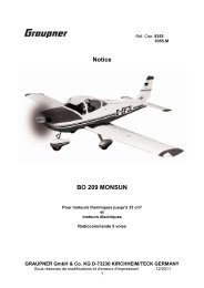
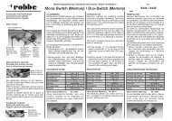
![[A]-SENSOR 150 A # 8 5405 - Weymuller Modélisme](https://img.yumpu.com/48234009/1/184x260/a-sensor-150-a-8-5405-weymuller-modaclisme.jpg?quality=85)