DOVETAIL JIG No. 860 - General Tools and Instruments
DOVETAIL JIG No. 860 - General Tools and Instruments
DOVETAIL JIG No. 860 - General Tools and Instruments

You also want an ePaper? Increase the reach of your titles
YUMPU automatically turns print PDFs into web optimized ePapers that Google loves.
<strong>DOVETAIL</strong> <strong>JIG</strong> <strong>No</strong>. <strong>860</strong><br />
USER’S MANUAL<br />
INTRODUCTION<br />
Thank you for purchasing <strong>General</strong>’s <strong>DOVETAIL</strong>ER Dovetail Jig. A simple <strong>and</strong> easy way to make professional furniture joints.<br />
SAFETY RULES FOR A HANDHELD ROUTER AND ROUTERS USED WITH A ROUTER TABLE<br />
1. KNOW YOUR ROUTER. Read the owner’s manual carefully before use. Learn the router's applications <strong>and</strong> limitations, as well as the<br />
specific potential hazards involved in its use.<br />
2. KEEP GUARDS IN PLACE <strong>and</strong> in working order.<br />
3. GROUND ALL TOOLS. Most routers are equipped with a three-prong plug, <strong>and</strong> it should be plugged into a three-hole electrical outlet. If an<br />
adapter is used to accommodate a two-prong outlet, the adapter lug must be attached to a known ground, such as the outlet holding<br />
screw. Never remove the third prong.<br />
4. REMOVE ANY ADJUSTING KEYS AND WRENCHES. Make it a habit to check that keys <strong>and</strong> adjusting wrenches are removed from the router<br />
before operating.<br />
5. KEEP WORK AREA CLEAN. Cluttered areas <strong>and</strong> benches invite accidents.<br />
6. AVOID POTENTIAL DANGERS. Don’t use your router in damp or wet locations, or expose them to rain. Keep work area well lighted.<br />
7. KEEP CHILDREN AND VISITORS AWAY. Distractions can easily lead to accidents — your own or others’.<br />
8. MAKE YOUR WORKSHOP CHILDPROOF. Use pad-locks, master switches, or remove start keys.<br />
9. DON’T FORCE THE ROUTER. It will do the job better <strong>and</strong> safer at the rate for which it was designed.<br />
10. WEAR PROPER APPAREL. <strong>No</strong> loose clothing, gloves, neckties, or jewelry to get caught in moving parts. <strong>No</strong>nslip footwear is recommended.<br />
Wear protective hair covering to contain long hair.<br />
11. USE SAFETY GLASSES.<br />
12. USE A FACE OR DUST MASK.<br />
13. DON’T OVERREACH. Keep your proper footing <strong>and</strong> balance at all times.<br />
14. MAINTAIN YOUR ROUTER IN TOP CONDITION. Keep router bits sharp <strong>and</strong> clean for best <strong>and</strong> safest performance. Follow instructions for<br />
lubricating <strong>and</strong> changing accessories.<br />
15. DISCONNECT YOUR ROUTER BEFORE SERVICING. Also when changing bits, blades, cutters <strong>and</strong> other accessories.<br />
16. USE ONLY RECOMMENDED ACCESSORIES. Consult the owner's manual for recommended accessories. The use of improper accessories<br />
may cause hazards.<br />
17. AVOID ACCIDENTAL STARTING. Make sure switch is in “OFF” position before plugging in cord.<br />
18. NEVER STAND ON A TOOL. Serious injury could occur if the tool is tipped or if the cutting tool is accidentally contacted.<br />
19. CHECK FOR DAMAGED PARTS. Before further use of the router, a guard or other part that is damaged should be carefully checked to<br />
ensure that it will operate properly <strong>and</strong> perform its intended function. Check for alignment of moving parts, breakage of parts, mounting,<br />
<strong>and</strong> any other conditions that may affect its operation. A guard or other part that is damaged should be properly repaired or replaced.<br />
20. ROUTER TABLE DIRECTION OF FEED. Feed work into the cutter.<br />
21. NEVER LEAVE THE ROUTER RUNNING UNATTENDED. Turn power off, <strong>and</strong> stay with router until it comes to a complete stop. Before leaving,<br />
assure that power cannot be turned on accidentally. Use pad-locks, master switches, or remove start keys.<br />
22. AVOID DRUGS, ALCOHOL, AND MEDICATION. Do not operate the a router while under the influence of drugs, alcohol or medication.<br />
1
POINTS TO NOTE BEFORE STARTING<br />
• Ensure that the bit is sharp. Blunt tools cannot produce good quality work, <strong>and</strong> increase the risk of a kickback <strong>and</strong> machine overload.<br />
• Advance the bit evenly <strong>and</strong> at a moderate pace to ensure longer bit life <strong>and</strong> to protect against overloads.<br />
• Cut long sockets in stages if necessary to avoid any buildup of chips.<br />
• After installation of a new milling bit make sure that it turns easily in the milling position.<br />
• Check the operation <strong>and</strong> setting of the tool on a sample piece before using on good wood.<br />
• Make sure both pieces of wood to be joined are perfectly flat by placing them against one another. Warped wood will cause an<br />
unsatisfactory joint.<br />
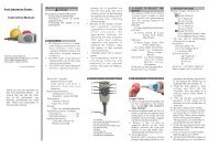
<strong>DOVETAIL</strong> <strong>JIG</strong> ASSEMBLY<br />
1. Remove all components from hardware bag <strong>and</strong> ensure that all are present <strong>and</strong> undamaged. (FIG.1)<br />
2. Install thumb screws into tapped holes as shown. Screw locations may be adjusted as needed. (FIG. 2)<br />
3. Press non-marring ends onto thumbscrews. (FIG. 3)<br />
QTY. 1<br />
14º<br />
1/2"x1/4"<br />
QTY. 2<br />
1/2" - OD<br />
1/4" - ID<br />
or<br />
USING THE DEPTH GAUGE<br />
The depth Gauge is used to set the<br />
depth of the Dovetail Cutter during<br />
router setup. It is also used to control<br />
the length of the pins during cutting.<br />
1. Loosen the two screws (A) on<br />
the face of the depth gauge<br />
2. Align the top surface (B) with<br />
the desired measurement on<br />
the ruled edges (C).<br />
3. Tighten the two screws (A) to<br />
lock the depth stop in position.<br />
QTY. 1<br />
14º<br />
1/2"x1/4"<br />
FIG. 2<br />
QTY. 4<br />
1/4" - 20<br />
QTY. 4 QTY. 1<br />
Included bearings are 1/2" outside diameter (OD). Router sleeves or bushings can be substituted as long as they are also 1/2" OD.<br />
Included router bit is 14° x 1/2". Other bits can be substituted providing they are also 1/2" diameter <strong>and</strong> their length is no greater than 3/4".<br />
C<br />
A<br />
2<br />
B<br />
FIG. 1<br />
FIG. 3<br />
FIG. 4
ROUTER SETUP<br />
1. Insert the dovetail cutter with the fixed bearing into the router.<br />
2. If the enclosed cutter is not of the fixed bearing type, install both bearings onto dovetail cutter <strong>and</strong> insert into Router. (FIG. 5)<br />
3. Set the height of the Dovetail Cutter Bit using the Depth Gauge. (FIG. 6)<br />
For instructions on setting the depth gauge see USING THE DEPTH GAUGE on page 2.<br />
4. FIG. 7 shows the dimension of the dovetail joint that the cutter height affects.<br />
5. The tightness of the joint (the fit between the two boards) can be adjusted by raising or lowering the height of the cutter as show in<br />
FIG. 8. This will be described in greater detail later.<br />
FIG. 8<br />
CUTTING A HALF BLIND <strong>DOVETAIL</strong> JOINT<br />
*The “PINS” side of the joint must be thicker than<br />
1/2" for Half-Blind Joints<br />
Setting a HIGHER bit height<br />
will produce a TIGHTER joint.<br />
Setting a LOWER bit height<br />
will produce a LOOSER joint.<br />
1. When cutting a half-blind dovetail joint, use the included<br />
1/2" x 1/2" cutter <strong>and</strong> start with a bit height setting of 1/2".<br />
2. Cut a test joint with scrap wood to confirm the fit of the joint.<br />
If the boards do not fit together easily, the joint may be too<br />
tight. The joint can be made looser or tighter by setting the<br />
cutter depth shallower or deeper as shown in FIG. 8.<br />
3. Begin with the “TAILS” side of the joint.<br />
4. Center the board in the “TAILS” portion of the jig with the<br />
outside face of the board facing inward. (FIG. 10)<br />
5. Tighten the thumbscrews. CAUTION: DO NOT OVERTIGHTEN THE<br />
THUMBSCREWS AS THIS HAS THE ABILITY TO WARP THE <strong>JIG</strong>.<br />
6. Clamp the board to a workbench or secure it in a vice as<br />
shown. (FIG. 11)<br />
7. Cut the “TAILS” portion of the joint. Be sure to follow the jig<br />
profile as the slots are wider than the cutter bearings. This is<br />
to allow for a rough <strong>and</strong> a finish pass.<br />
8. <strong>No</strong>w it is time to make the “PINS” side of the joint.<br />
9. Set the depth gauge to the desired length of the “PINS”. This<br />
should be slightly greater than the thickness of the wood used<br />
for the “TAILS” board. (FIG. 12)<br />
FIG. 5 FIG. 6<br />
3<br />
PINS<br />
TAILS<br />
FIG. 7<br />
FIG. 9
10. Loosely clamp the “PINS” wood into the jig with the outside face<br />
pointing inward.<br />
11. Insert the “TAILS” from previous cut into the teeth on the bottom of<br />
adjuster plate. Position the wood to be cut by lining up the sides<br />
with the first piece. (FIG. 13)<br />
12. With the edges of both boards aligned; tighten the thumbscrews<br />
(NOTE THE CAUTION FROM STEP #5) <strong>and</strong> secure the stock to the<br />
bench. Remove the “TAILS” board before proceeding.<br />
13. Make all cuts. For this cut the router should ride on the surface of<br />
the depth plate as shown in FIG. 14. Be sure to follow the jig profile<br />
as the slots are wider than the cutter bearings. This is to allow for<br />
a rough <strong>and</strong> a finish pass.<br />
14. Before gluing, fit the two sections together. The joint should be<br />
tight <strong>and</strong> even with no gaps. If problems arise, file or trim the<br />
joint to improve the fit.<br />
FIG. 11<br />
FIG. 13<br />
SIDES LINE UP<br />
CUTTING A FULL THROUGH <strong>DOVETAIL</strong> JOINT<br />
*This requires a dovetail cutter bit with a depth greater than<br />
the wood you are cutting.<br />
The steps required to cut a full through joint (FIG. 15) are very similar<br />
to those described in the previous section CUTTING A HALF BLIND<br />
<strong>DOVETAIL</strong> JOINT, with the following exceptions:<br />
1. When cutting the “TAILS” (FIG. 15) portion of the joint, set the bit<br />
depth to slightly greater than the thickness of the “PINS” board.<br />
This will ensure that the tails are slightly proud when fit <strong>and</strong> can<br />
be s<strong>and</strong>ed down for a flush fit. (FIG. 16)<br />
2. When cutting the “PINS” portion of the joint, set the cutter depth<br />
deeper (tighter) first <strong>and</strong> adjust to the desired joint fit.<br />
CUTTING JOINTS WIDER THAN 6"<br />
Joints over 6" wide must be cut in multiple<br />
segments. To align the jig with the previous cut,<br />
the aligning tool must be used.<br />
1. Move the wood in the jig <strong>and</strong> position the last slot from the<br />
previous cut in the last channel of the jig.<br />
2. Loosely clamp the wood in the jig.<br />
3. Insert the aligning tool into the slot to properly center the wood<br />
with the jig. (FIG. 17)<br />
4. Tighten the thumbscrews, (CAUTION: DO NOT OVERTIGHTEN),<br />
<strong>and</strong> continue cutting.<br />
5. Repeat as necessary.<br />
4<br />
FIG. 14<br />
FIG. 15<br />
FIG. 16<br />
INSIDE FACE<br />
PINS<br />
TAILS<br />
FIG. 10<br />
FIG. 12
EDGE JOINTING (FIG. 22)<br />
1. In order to join two pieces of wood using a Dovetail-Joint the<br />
round-over created by the dovetail jig must be avoided. (FIG. 18)<br />
2. Insert the first board into the “TAILS” section of the Dovetail Jig<br />
along with a thin piece of scrap at least 1/4" thick to offset the<br />
first board <strong>and</strong> the jig. (FIG. 19)<br />
3. Align one edge of the board to be cut with the outside edge of<br />
the jig. (FIG. 20)<br />
4. Tighten the thumbscrews, (CAUTION: DO NOT OVERTIGHTEN),<br />
<strong>and</strong> make all cuts.<br />
5. Insert the second board into the jig along with the same scrap<br />
wood <strong>and</strong> offset one edge of the board 1/2" from the outside<br />
edge of the jig. (Fig. 21) This spacing will offset the “TAILS” of<br />
the second board so that they align with the slots cut into the<br />
first board.<br />
FIG. 23<br />
FIG. 22<br />
CUTTING A BOX JOINT (FIG. 23)<br />
For box jointing, use a 1/2" diameter straight bit with either a 1/2"<br />
O.D. top guide bearing or a 1/2" O.D. guide sleeve insert in your router.<br />
Set the depth of the cutter to equal, or slightly greater than the<br />
thickness of the stock you’re joining.<br />
Tip: Always make sure that the guide bearing or the guide sleeve<br />
tracks in the guide slot.<br />
To avoid the “round-over” part of the guide finger of the jig, use a<br />
1/4" thick piece of scrap as a shim between the wood <strong>and</strong> the inner<br />
surface of the jig to offset the board from the “round-over”. (FIG. 19)<br />
Tip: If you’re doing more than one joint, you can use a piece of<br />
double-face tape to hold the shim in place.<br />
Cut the slots in the first board with the board edge set flush with the<br />
right h<strong>and</strong> edge of the jig. (FIG. 20) Make the entry <strong>and</strong> exit cuts using<br />
the left side of the guide slot only.<br />
For the joining board, clamp it in the jig with its edge offset 3/8" in<br />
from the right h<strong>and</strong> edge of the jig (FIG. 21), except use 3/8" offset<br />
instead of 1/2". Make entry <strong>and</strong> exit cuts using the right side of the<br />
guide slot only.<br />
Dry fit the joint before gluing to be sure it is tight. If necessary, use a<br />
wood mallet to bring the two parts together.<br />
5<br />
ROUND-OVER<br />
SCRAP<br />
3/8" offset for Box Joint<br />
1/2" offset for Edge Joint<br />
FIG. 17<br />
FIG. 18<br />
FIG. 19<br />
FIG. 20<br />
FIG. 21
ACCESORIO PARA COLA DE MILANO<br />
<strong>No</strong>. <strong>860</strong><br />
MANUAL DE INSTRUCCIONES<br />
NORMAS DE SEGURIDAD PARA FRESADORA HOGAREÑA Y FRESADORAS DE MESA<br />
1. CONOZCA SU FRESADORA. Lea cuidadosamente el manual del propietario antes de usarla. Aprenda sus aplicaciones y limitaciones así<br />
también como los peligros potenciales específicos relativos a su uso.<br />
2. MANTENGA LAS CUBIERTAS EN SU LUGAR y funcion<strong>and</strong>o correctamente.<br />
3. CONECTE TODAS LAS HERRAMIENTAS A TIERRA. La mayoría de las fresadoras tienen un enchufe de tres patas, y deben enchufarse en un<br />
tomacorriente de tres orificios. Si utiliza un adaptador para conectarla a un tomacorriente de dos orificios, el cable de tierra del<br />
adaptador debe conectarse a una toma de tierra adecuada, como el tornillo de montaje del tomacorriente. Nunca remueva la tercera<br />
pata.<br />
4. QUITE TODAS LAS LLAVES Y LAS PINZAS DE AJUSTE. Acostúmbrese a verificar que las llaves y pinzas de ajuste se hayan sacado de la<br />
fresadora antes de usarla.<br />
5. MANTENGA LIMPIA EL ÁREA DE TRABAJO. Las áreas y bancos de trabajo abarrotados provocan accidentes.<br />
6. EVITE LOS PELIGROS POTENCIALES. <strong>No</strong> utilice la fresadora en lugares húmedos o mojados ni las exponga a la lluvia. Mantenga el área de<br />
trabajo bien iluminada.<br />
7. MANTENGA ALEJADOS A LOS NIÑOS Y A LOS OBSERVADORES. Las distracciones pueden fácilmente causar accidentes – a usted y a los<br />
demás.<br />
8. HAGA SU LUGAR DE TRABAJO A PRUEBA DE NIÑOS. Use c<strong>and</strong>ados, interruptores maestros o quite las llaves de encendido.<br />
9. NO FUERCE LA FRESADORA. Hará el trabajo mejor y de forma más segura a la velocidad para la cual fue diseñada.<br />
10. USE LA INDUMENTARIA ADECUADA. <strong>No</strong> use ropa suelta, guantes, corbatas o joyas que puedan ser atrapadas por partes en movimiento. Le<br />
recomendamos usar calzado antideslizante. Si tiene el cabello largo, use alguna cubierta para protegerlo.<br />
11. USE GAFAS PROTECTORAS.<br />
12. USE UNA MÁSCARA PARA LA CARA O CONTRA EL POLVO.<br />
13. NO SE EXTIENDA DEMASIADO. Mantenga su superficie de apoyo y balance adecuado todo el tiempo.<br />
14. MANTENGA SU FRESADORA EN ÓPTIMAS CONDICIONES. Mantenga las puntas de la fresadora afiladas y limpias para un rendimiento<br />
mejor y más seguro. Siga las instrucciones para su lubricación y cambio de accesorios.<br />
15. DESCONECTE SU FRESADORA ANTES DE HACERLE MANTENIMIENTO. También al limpiar las puntas, cuchillas, hojas y demás accesorios.<br />
16. UTILICE ÚNICAMENTE LOS ACCESORIOS RECOMENDADOS. Consulte el manual del propietario acerca de los accesorios recomendados. El<br />
uso de accesorios inadecuados puede ser peligroso.<br />
17. EVITE LOS ARRANQUES ACCIDENTALES. Verifique que el interruptor esté en la posición “OFF” antes de enchufar el cable.<br />
18. NUNCA SE PARE SOBRE UNA HERRAMIENTA. Podría sufrir heridas graves si se cae la herramienta o si entra en contacto accidentalmente<br />
con la herramienta de corte.<br />
19. VERIFIQUE QUE NO HAYA PARTES ROTAS. Antes de seguir us<strong>and</strong>o la fresadora, una cubierta u otra parte dañada debe revisarse<br />
cuidadosamente para verificar que funcione correctamente y que cumpla con su función específica. Verifique la alineación de las partes<br />
móviles, roturas, montajes y cualquier otra cosa que pudiera afectar su funcionamiento. Una cubierta o cualquier otra parte dañada debe<br />
ser correctamente reparada o reemplazada.<br />
20. DIRECCIÓN DE ALIMENTACIÓN DE LA MESA FRESADORA. Alimente la pieza de trabajo hacia la fresadora.<br />
21. NUNCA DEJE LA FRESADORA FUNCIONANDO DESATENDIDA. Apague la alimentación y permanezca con la fresadora hasta que se detenga<br />
por completo. Antes de irse, asegúrese de que no pueda encenderse por accidente. Use c<strong>and</strong>ados, interruptores maestros o quite las<br />
llaves de encendido.<br />
22. EVITE LAS DROGAS, EL ALCOHOL Y LA MEDICACIÓN. <strong>No</strong> use la fresadora cu<strong>and</strong>o esté bajo la influencia de drogas, alcohol o medicación.<br />
6
PUNTOS IMPORTANTES ANTES DE COMENZAR<br />
• Verifique que la punta esté afilada. Las herramientas desafiladas no pueden producir trabajo de buena calidad e incrementan el riesgo de<br />
contragolpes y sobrecarga de la máquina.<br />
• Haga avanzar la punta de forma pareja y a una velocidad moderada para prolongar la vida de la punta y protegerla contra sobrecargas.<br />
• Haga los cortes largos en etapas si es necesario, para evitar la acumulación de aserrín.<br />
• Luego de instalar una punta fresadora nueva verifique que se mueva libremente en su posición de trabajo.<br />
• Verifique el funcionamiento y ajuste de la herramienta en una pieza de prueba antes de usarla en la pieza final.<br />
• Verifique que las dos piezas de madera a unir sean perfectamente planas coloc<strong>and</strong>o una contra la otra. La madera arqueada resultará en<br />
una unión insatisfactoria.<br />
CONJUNTO DE COLA DE MILANO<br />
1. Saque todos los componentes de la bolsa y verifique que no falte nada y que no estén dañados. (Fig. 1)<br />
2. Instale los tornillos de ajuste manual en los orificios roscados como se indica. Se puede cambiar la ubicación de los tornillos si es<br />
necesario. (Fig. 2)<br />
3. Presione los extremos sin marcas con los tornillos de ajuste manual. (Fig. 3)<br />
CANT. 1<br />
14º<br />
1/2"x1/4"<br />
CANT. 2<br />
1/2" - DE<br />
1/4" - DI<br />
USANDO EL MEDIDOR DE<br />
PROFUNDIDAD<br />
El medidor de profundidad se usa<br />
para ajustar la profundidad del corte<br />
de cola de milano durante el ajuste de<br />
la fresadora. También se usa para<br />
controlar la longitud de las clavijas<br />
durante el corte.<br />
1. Afloje los dos tornillos (A) de la<br />
cara del medidor de profundidad.<br />
2. Alinee la superficie superior (B) con<br />
la medida deseada del borde<br />
graduado (C).<br />
3. Ajuste los dos tornillos (A) para<br />
trabar el tope de profundidad en su<br />
lugar.<br />
o<br />
CANT. 1<br />
14º<br />
1/2"x1/4"<br />
FIG. 2<br />
7<br />
CANT. 4<br />
1/4" - 20<br />
CANT. 4 CANT. 1<br />
Los rodamientos incluidos tienen 1/2" de diámetro externo (DE). Se pueden sustituir las mangas o cojinetes de la fresadora siempre y<br />
cu<strong>and</strong>o tengan 1/2" de DE.<br />
La punta de fresadora incluida<br />
es de 14° x 1/2". Se puede sustituir<br />
por otras puntas siempre y cu<strong>and</strong>o<br />
también tengan 1/2" de diámetro y<br />
no sean más largas que 3/4".<br />
B<br />
C<br />
A<br />
FIG. 3<br />
FIG. 4
AJUSTE DE LA FRESADORA<br />
1. Inserte la fresa para cola de milano con el cojinete fijo en la fresadora.<br />
2. Si la fresa que se adjunta no es del tipo de cojinete fijo, instale ambos cojinetes en la fresa para cola de milano e insértela en la fresadora.<br />
(FIGURA 5)<br />
3. La Fig. 7 muestra la dimensión de la unión de cola de milano afectada por la altura de la cuchilla de corte.<br />
4. Se puede ajustar cuán estrecha será la unión (cuanto juego tendrán las partes) subiendo o baj<strong>and</strong>o la altura de la hoja de corte como se<br />
muestra en la Fig. 8. Esto se describe en mayor detalle más adelante.<br />
FIG. 8<br />
Ajust<strong>and</strong>o la punta HACIA ARRIBA<br />
producirá una unión MÁS AJUSTADA.<br />
Ajust<strong>and</strong>o la punta HACIA ABAJO<br />
producirá una unión MÁS FLOJA.<br />
CORTANDO UNA UNIÓN COLA DE MILANO INVISIBLE<br />
* El lado de las “CLAVIJAS” de la unión debe ser más grueso que<br />
1/2" para uniones invisibles<br />
1. Al cortar una unión cola de milano invisible, use la hoja de corte<br />
de 1/2" x 1/2" incluida y comience con una profundidad de punta<br />
de 1/2".<br />
2. Haga una unión de prueba con madera de desecho para confirmar<br />
el encastre de la unión. Si las placas no se encastran fácilmente,<br />
la unión puede ser demasiado ajustada. Se puede hacer la unión<br />
más floja o más ajustada ajust<strong>and</strong>o la profundidad de corte hacia<br />
arriba o hacia abajo como se muestra en la Fig. 8.<br />
3. Comience por el lado de las “COLAS” de la unión.<br />
4. Centre la placa en la porción de las “COLAS” con la cara externa<br />
de la placa mir<strong>and</strong>o hacia adentro (Fig. 10).<br />
5. Ajuste los tornillos manuales. PRECAUCIÓN: NO AJUSTE DE MÁS<br />
LOS TORNILLOS MANUALES YA QUE PODRÍA ARQUEAR EL<br />
CONJUNTO.<br />
6. Fije la placa a un banco de trabajo o asegúrela en una prensa<br />
como se muestra (Fig. 11).<br />
7. Corte el lado de las “COLAS” de la unión. Asegúrese de seguir el<br />
perfil de la plantilla ya que las ranuras son más anchas que los<br />
rodamientos de las cuchillas. Esto permite hacer una pasada<br />
rápida y una de acabado.<br />
8. Ahora es el momento de hacer el lado de las “CLAVIJAS” de la<br />
unión.<br />
FIG. 5 FIG. 6<br />
8<br />
CLAVIJAS<br />
COLAS<br />
FIG. 7<br />
FIG. 9
9. Ajuste el medidor de profundidad a la longitud deseada de las<br />
“CLAVIJAS”. Esta debe ser levemente mayor que el espesor de la<br />
madera usada para la placa de las “COLAS”. (Fig. 12).<br />
10. Ajuste levemente la madera de las “CLAVIJAS” en el dispositivo<br />
con la cara externa apunt<strong>and</strong>o hacia adentro.<br />
11. Inserte las “COLAS” del corte anterior en los dientes de la parte<br />
inferior de la placa de ajuste. Coloque la madera a cortar<br />
aline<strong>and</strong>o los lados con la primera pieza. (Fig. 13).<br />
12. Con los bordes de ambas placas alineados, ajuste los tornillos<br />
manuales (VER EL AVISO DE PRECAUCIÓN DEL PASO #5) y asegure<br />
el conjunto al banco de trabajo. Saque la placa de las “COLAS”<br />
antes de proceder.<br />
13. Haga todos los cortes. Para este corte, la fresadora debe<br />
deslizarse por la superficie de la placa de profundidad como se<br />
muestra en la Fig. 14. Asegúrese de seguir el perfil de la plantilla<br />
ya que las ranuras son más anchas que los rodamientos de las<br />
cuchillas. Esto permite hacer una pasada rápida y una de<br />
acabado.<br />
14. Antes de encolarla, encastre las dos partes entre sí. La unión debe<br />
quedar ajustada y pareja, sin espacios. Si surge algún problema,<br />
lime o rebaje la unión para mejorar su encastre.<br />
FIG. 12<br />
FIG. 13<br />
LADOS ALINEADOS<br />
CORTANDO UNA UNIÓN COLA DE MILANO PASANTE<br />
* Esto requiere una punta de corte cola de milano más profunda que<br />
la madera que esté cort<strong>and</strong>o.<br />
Los pasos necesarios para cortar una unión pasante (Fig. 15) son muy<br />
parecidos a los descritos en la sección anterior CORTANDO UNA<br />
UNIÓN COLA DE MILANO INVISIBLE. Con las siguientes excepciones:<br />
1. Al cortar las “COLAS” de la unión, ajuste la profundidad de la punta<br />
a un poco más que el espesor de la madera de las “CLAVIJAS”.<br />
Esto asegurará que las colas queden levemente más profundas al<br />
encastrarlas y se podrán lijar para que queden al ras. (Fig.16)<br />
2. Al cortar las “CLAVIJAS” de la unión, ajuste primero la profundidad<br />
de corte un poco más profunda (ajustada) y ajústela hasta el<br />
encastre deseado de la unión.<br />
CORTANDO UNIONES MÁS ANCHAS<br />
QUE 6"<br />
Las uniones de más de 6" deben cortarse en varios<br />
segmentos. Para alinear el dispositivo con el corte<br />
anterior, deberá usar la herramienta de alineación.<br />
1. Mueva la madera dentro del dispositivo y<br />
coloque la última ranura del corte anterior en el último canal<br />
del dispositivo. (Fig. 17)<br />
2. Ajuste levemente la madera en el dispositivo.<br />
3. Inserte la herramienta de alineación en la ranura para centrar<br />
correctamente la madera con el dispositivo.<br />
4. Ajuste los tornillos manuales (PRECAUCIÓN: NO ADJUSTE DE MÁS<br />
LOS TORNILLOS MANUALES) y haga todos los cortes.<br />
5. Repítalo como sea necesario.<br />
9<br />
FIG. 11<br />
FIG. 14<br />
FIG. 15<br />
FIG. 16<br />
CARA INTERNA<br />
CLAVIJAS<br />
COLAS<br />
FIG. 10
ENSAMBLADURA DE BORDES<br />
1. Para poder unir dos piezas de madera us<strong>and</strong>o una junta de cola de<br />
milano, deberá evitar el redondeado creado por el dispositivo de<br />
cola de milano. (Fig. 18)<br />
2. Inserte la primera tabla en la sección “COLAS” de la plantilla para<br />
colas de milano, con un pedazo delgado de al menos 1/4" de<br />
espesor para ajustar la primera tabla y la plantilla. (FIGURA 19)<br />
3. Alinee un extremo de la placa a cortar con el borde externo del<br />
dispositivo. (Fig. 20)<br />
4. Ajuste los tornillos manuales (PRECAUCIÓN: NO ADJUSTE DE MÁS<br />
LOS TORNILLOS MANUALES) y haga todos los cortes.<br />
5. Inserte la segunda tabla en la plantilla con la ayuda del mismo<br />
pedazo de madera y ajuste un borde de la tabla a 1/2" del borde<br />
externo de la plantilla. Este espaciado ajustará las “COLAS” de la<br />
segunda tabla para que se alineen con las ranuras cortadas en la<br />
primera tabla. (FIGURA 21)<br />
CORTE DE UNA ENSAMBLADURA DE CAJA<br />
FIG. 22<br />
FIG. 23<br />
Para ensambladuras de caja utilice una broca recta de 1/2” de<br />
diámetro, con un cojinete de guía superior de 1/2” de diámetro<br />
externo o un encastre de casquillo guía de 1/2” de diámetro externo<br />
en su fresadora. Establezca la profundidad de la fresa a un espesor<br />
igual o ligeramente mayor al material que está uniendo.<br />
Consejo: Siempre asegúrese de que el cojinete guía o el casquillo guía<br />
se encuentre en la ranura de la guía.<br />
Para evitar la parte “redondeada” del dedo de la guía de la plantilla,<br />
use un pedazo de madera de 1/4” de espesor como cuña entre la<br />
madera y la superficie interna de la plantilla para desplazar la parte<br />
“redondeada” de la tabla (figura 19, página 5).<br />
Consejo: Si está realiz<strong>and</strong>o más de una ensambladura, puede utilizar<br />
un pedazo de cinta adhesiva de doble cara para mantener las cuñas<br />
en su lugar.<br />
Corte las ranuras en la primera tabla con el borde de la tabla montado<br />
con el borde derecho de la plantilla (consulte la figura 20, página 5).<br />
Realice los cortes de entrada y salida utiliz<strong>and</strong>o únicamente el lado<br />
izquierdo de la ranura guía.<br />
Para la tabla de unión, sujétela en la plantilla con su borde ajustado a<br />
3/8” del borde del lado derecho de la plantilla (consulte la figura 21,<br />
página 5, excepto que use un desplazamiento de 3/8” en lugar de uno<br />
de 1/2”). Realice los cortes de entrada y salida utiliz<strong>and</strong>o únicamente<br />
el lado derecho de la ranura guía.<br />
Coloque la unión antes de colocarle pegamento para asegurarse de<br />
que esté apretada. Si resulta necesario, utilice un mazo de madera<br />
para unir ambas partes.<br />
10<br />
REDONDEADO<br />
DESECHO<br />
Wood is flush to edge of jig<br />
Desplazamiento de 3/8" para ensambladura de caja<br />
Desplazamiento de 1/2" para ensambladura de bordes<br />
FIG. 17<br />
FIG. 18<br />
FIG. 19<br />
FIG. 20<br />
FIG. 21
GABARIT EN QUEUE D’ARONDE<br />
<strong>No</strong>. <strong>860</strong><br />
MANUEL D’INSTRUCTIONS<br />
RÈGLES DE SÉCURITÉ POUR UNE TOUPIE PORTATIVE ET LES TOUPIES UTILISÉES AVEC UNE TABLE À TOUPIE<br />
1. APPRENEZ À CONNAÎTRE VOTRE TOUPIE. Lisez soigneusement le manuel de l'utilisateur avant de l’utiliser. Apprenez les usages ainsi que<br />
les limitations de la toupie et les dangers potentiels faisant partie de son utilisation.<br />
2. GARDEZ L’ÉCRAN PROTECTEUR en place et en bon état.<br />
3. TOUS LES OUTILS DOIVENT ÊTRE MIS À LA TERRE. La plupart des toupies sont équipées d'une prise à trois broches, et il doit être branché<br />
dans une prise électrique à trois trous. Si un adaptateur est utilisé pour ajuster une prise à deux broches, le crochet de l’adaptateur doit<br />
être attaché à un sol connu, tel que la prise qui retient la vis. N'enlevez jamais la troisième broche.<br />
4. ENLEVER TOUTES LES CLÉS DE RÉGLAGE Prenez l’habitude de vérifier que les clés de réglage sont enlevées de la toupie avant de le faire<br />
fonctionner.<br />
5. GARDEZ L’AIRE DE TRAVAIL PROPRE. Les endroits et les établis encombrés attirent les accidents.<br />
6. ÉVITEZ D’ÉVENTUELS DANGERS. N’utilisez jamais votre toupie dans des endroits humides ou mouillés ou les exposer au soleil. Garder<br />
votre surface de travail bien éclairée.<br />
7. GARDEZ LES ENFANTS ET LES VISITEURS À DISTANCE. Les distractions peuvent facilement conduire à des accidents – vôtres ou des<br />
autres.<br />
8. TRANSFORMEZ VOTRE ATELIER À L'ÉPREUVE DES ENFANTS. Utilisez des cadenas, interrupteurs centraux ou enlevez les clés de<br />
démarrage.<br />
9. NE FORCEZ PAS LA TOUPIE. Il fera le travail plus efficacement et de façon plus sécuritaire au régime pour lequel il a été fabriqué.<br />
10. PORTEZ DES VÊTEMENTS APPROPRIÉS. Pas de vêtements amples, gants, cravates ou bijoux puisqu'ils peuvent s'accrocher à des pièces en<br />
mouvement. Les chaussures antidérapantes sont recomm<strong>and</strong>ées. Portez une protection pour les cheveux pour couvrir les cheveux longs.<br />
11. UTILISEZ DES LUNETTES DE SÉCURITÉ.<br />
12. UTILISEZ UN PROTECTEUR FACIAL OU UN MASQUE ANTI-POUSSIÈRE.<br />
13. N’UTILISEZ PAS SUR DE TROP GROS OBJETS. Maintenez votre bon appui et restez en équilibre en tout temps.<br />
14. GARDEZ VOTRE TOUPIE EN EXCELLENT ÉTAT. Gardez les mèches de toupie bien aiguisés et propres pour la meilleure performance et la<br />
plus sécuritaire. Suivez les instructions de lubrication et de changement des accessoires.<br />
15. DÉBRANCHEZ VOTRE TOUPIE AVANT DE FAIRE LE SERVICE. Faites-le aussi lorsque vous changez les mèches, les lames, les couteaux, et<br />
les autres accessoires.<br />
16. UTILISER DES ACCESSOIRES RECOMMANDÉS UNIQUEMENT. Consultez le manuel de l’utilisateur pour les accessoires recomm<strong>and</strong>és.<br />
L'utilisation d'accessoires non recomm<strong>and</strong>és peut causer des risques.<br />
17. ÉVITER LES DÉMARRAGES ACCIDENTELS. Assurez-vous que les interrupteurs soient à la position d’arrêt (OFF) avant de brancher au<br />
cordon.<br />
18. NE MONTEZ JAMAIS SUR UN OUTIL. Des blessures graves pourraient se produit si l’outil est penché ou si l’outil de coupage est en<br />
contact accidentellement.<br />
19. VÉRIFIER SI LES PIÈCES SONT ENDOMMAGÉES. Avant d'utiliser la toupie, une protection ou une autre partie endommagée doit être<br />
inspectée soigneusement pour s'assurer d'une opération adéquate et d'un fonctionnement normal. Soyez attentifs à tout alignement des<br />
pièces en mouvement, à tout bris, montage ou à toute autre condition préjudiciable au bon fonctionnement de l’outil. Un protège-lame ou<br />
toute autre partie qui est endommagée doit être correctement réparée ou remplacée.<br />
20. DIRECTION DE LA TABLE À TOUPIE DU MÉCANISME D’ALIMENTATION. Mâchez le travail dans le couteau.<br />
21. NE LAISSEZ JAMAIS LA TOUPIE EN MARCHE SANS SURVEILLANCE. Mettez-le en arrêt et restez avec la toupie jusqu’à ce qu’il soit en arrêt<br />
complètement. Avant de partir, assurez-vous que l’alimentation ne puisse pas être activée accidentellement. Utilisez des cadenas,<br />
interrupteurs centraux ou enlevez les clés de démarrage.<br />
22. ÉVITEZ LES DROGUES, L’ALCOOL ET LES MÉDICAMENTS. N’utilisez pas la toupie si vous êtes sous l'influence de drogues, d'alcool, ou de<br />
médicaments.<br />
11
POINTS À REMARQUER AVANT DE COMMENCER<br />
• Assurez-vous que la mèche est aiguisée. Les outils épointés ne peuvent pas produire une bonne qualité de travail, et augmentent le risque<br />
de recul et de surcharge de la machine.<br />
• Passez la mèche de manière uniforme et à un rythme modéré pour vous assurer une durée de vie de la mèche plus longue et pour la<br />
protéger contre les surcharges.<br />
• Coupez des longues douilles en étapes si nécessaire, afin d'éviter toute accumulation des croustilles.<br />
• Après l’installation de la nouvelle mèche de moulage, assurez-vous qu’elle tourne facilement en position de moulage.<br />
• Vérifiez le fonctionnement et le réglage de l’outil sur un échantillon avant de l’utiliser sur le bon bois.<br />
• Assurez-vous que les deux morceaux de bois à assembler sont parfaitement plat en les plaçant l’un contre l’autre. Du bois gauchi<br />
provoquera un joint insatisfaisant.<br />
ASSEMBLAGE DE GABARIT DE QUEUE D’ARONDE<br />
1. Enlevez tous les composants de la valise de matériel et assurez-vous qu'ils sont tous là et intacts. (fig.1)<br />
2. Installez les vis à oreille dans les trous filetés comme illustré. Les endroits des vis peuvent être ajustés au besoin. (fig. 2)<br />
3. Appuyez les extrémités de protection sur les vis à oreilles. (fig. 3)<br />
QTÉ. 1<br />
14º<br />
1/2"x1/4"<br />
QTE. 2<br />
1/2" - OD<br />
1/4" - DI<br />
ou<br />
Les coussinets inclus possèdent un diamètre extérieur de 1/2 po (OD). Les manchons de toupie ou les coussinets sont interchangeables en<br />
autant qu'ils possèdent un diamètre extérieur (OD) identique de 1/2 po.<br />
Comprend une mèche à toupie de<br />
14° x 1/2 po. D'autres mèches<br />
peuvent être interchangeables à<br />
condition qu'ils possèdent un<br />
diamètre de 1/2 po et que la longueur<br />
B<br />
ne soit pas supérieure à 3/4 po.<br />
UTILISER L’INDICATEUR<br />
D’ENFONCEMENT<br />
L’indicateur d’enfoncement est utilisé<br />
pour régler la profondeur du couteau<br />
de queue d’aronde lors de la<br />
configuration de la toupie. Il est aussi<br />
utilisé afin de contrôler la longueur<br />
des iges lors du coupage.<br />
1. Desserrez les deux vis (A) sur la<br />
face de l’indicateur d’enfoncement.<br />
2. Alignez la surface supérieure (B)<br />
avec la mesure désirée sur le bord<br />
réglementé (C).<br />
3. Serrez les deux vis (A) pour<br />
verrouiller l’arrêt de la profondeur<br />
à la bonne position.<br />
QTE. 1<br />
14º<br />
1/2"x1/4"<br />
C<br />
A<br />
FIG. 2<br />
QTE. 4<br />
1/4" - 20<br />
12<br />
QTE. 4 QTE. 1<br />
FIG. 3<br />
FIG. 4
RÉGLAGE DE LA TOUPIE<br />
1. Insérez la fraise pour queues d’aronde avec le support fixe dans la toupie.<br />
2. Si la fraise fournie n’est pas de type à support fixe, installez les supports sur la fraise et insérez l’ensemble dans la toupie. (FIG. 5)<br />
3. La fig. 7 montre les dimensions du joint de queue d’aronde qui est influé par la hauteur du couteau.<br />
4. La contraction du joint (l’adéquation entre les deux tableaux) peut être réglée en augmentant ou en réduisant la hauteur des couteaux<br />
comme illustré dans la fig. 8. Ceci sera décrit plus en détail plus tard.<br />
FIG. 8<br />
Régler la mèche avec une hauteur PLUS ÉLEVÉE<br />
causera un joint PLUS SERRÉ.<br />
Régler la mèche avec une hauteur MOINS ÉLEVÉE<br />
causera un joint PLUS DESSERRÉ.<br />
COUPER UN JOINT DE QUEUE D'ARONDE SEMI-AVEUGLE<br />
* Le côté des « TENONS » du joint doit être plus épais que 1/2 po<br />
pour les joints semi-aveugles.<br />
1. Lorsque vous coupez un joint de queue d’aronde semi-aveugle,<br />
utilisez le couteau inclus de 1/2 po x 1/2 po et commencez avec TENONS<br />
un réglage de la hauteur de la mèche de 1/2 po.<br />
2. Coupez un joint d’essai avec un petit morceau de bois pour<br />
confirmer l’adéquation du joint. Si les tableaux ne s’ajustent pas<br />
ensemble facilement, le joint est peut-être trop serré. Le joint<br />
peut être plus desserré ou plus serré en réglant la profondeur de<br />
coupe moins ou plus profonde comme montré dans la fig. 8.<br />
3. Débutez avec le côté « QUEUES » du joint.<br />
4. Centrez la plaque dans la portion « QUEUES » du serre-joint,<br />
la face extérieure de la plaque vers l'intérieur (fig. 10).<br />
5. Serrez les vis à serrage à la main. MISE EN GARDE : NE PAS TROP<br />
SERRER LES VIS À SERRAGE À la MAIN CAR CELLES-CI PEUVENT<br />
AVOIR UN EFFET DE GAUCHISSEMENT SUR LE<br />
SERRE-JOINT.<br />
6. Fixez la plaque dans l'étrier d'un établi ou fixez-la solidement<br />
dans un étau, tel qu'illustré (fig. 11).<br />
7. Coupez la portion « QUEUES » du joint. Assurez-vous de suivre le<br />
profil du serre-joint puisque les fentes sont plus larges que les<br />
coussinets. Cela permet une coupe rude et de finition.<br />
8. Vous pouvez maintenant faire le côté « TENONS » du joint.<br />
9. Ajustez la jauge de profondeur à la longueur désirée de<br />
« TENONS ». Elle devrait être légèrement plus longue que<br />
l'épaisseur du bois utilisé pour les planches « QUEUES » (fig. 12).<br />
FIG. 5 FIG. 6<br />
13<br />
QUEUES<br />
FIG. 7<br />
FIG. 9
10. Fixez doucement les « TENONS » de bois dans le serre-joint, la face<br />
extérieure pointant vers l'intérieur.<br />
11. Insérez les « QUEUES » des coupes précédentes dans la dent<br />
inférieure de la plaque d'ajustement. Positionnez le bois à couper en<br />
l'alignant avec les côtés de la première pièce (fig. 13).<br />
12. Les rebords maintenant alignés des deux côtés de la planche, serrez<br />
les vis à la main (VOYEZ LA MISE EN GARDE À L'ÉTAPE NO. 5) et fixez<br />
l'assemblage à l'établi. Retirez les « QUEUES » de planche avant de<br />
continuer.<br />
13. Effectuez toutes vos coupes. Pour cette coupe, la toupie devrait<br />
patiner à la surface de la plaque de profondeur, tel qu'illustré à la<br />
figure 14. Assurez-vous de suivre le profil du serre-joint car les<br />
fentes sont plus larges que les coussinets. Cela permet une coupe<br />
rude et de finition.<br />
14. Avant de coller, ajustez les deux sections ensemble. Le joint doit<br />
être serré et même sans ouvertures. Si un problème arrive,<br />
aiguisez ou taillez le joint pour améliorer la forme.<br />
FIG. 12<br />
FIG. 13<br />
CÔTÉS ALIGNÉS<br />
COUPER UN JOINT DE QUEUE D’ARONDE COMPLET<br />
* Ceci exige une mèche de couteau de queue d’aronde avec une<br />
profondeur plus gr<strong>and</strong>e que celle du bois que vous coupez.<br />
Les étapes exigées pour couper un au complet (fig. 15) sont très<br />
similaires à celles décrites dans la section précédente COUPER UN<br />
JOINT DE QUEUE D'ARONDE SEMI-AVEUGLE. Avec les exceptions<br />
suivantes:<br />
1. Lorsque vous coupez des « QUEUES » du joint, réglez la profondeur<br />
de la mèche un peu plus gr<strong>and</strong>e que l’épaisseur des « TENONS ».<br />
Ceci assurera que les queues soient un peu plus fières lors de<br />
l’ajustement et peuvent être poncées pour les accoter directement.<br />
(fig. 16)<br />
2. Lorsque vous coupez les « TENONS » du joint, réglez premièrement<br />
la profondeur du couteau plus profond (plus serré) et puis ajustez<br />
à la forme désirée du joint.<br />
COUPER DES JOINTS PLUS GRANDS QUE<br />
6 PO<br />
Les joints de plus de 6 po de large doivent être coupés<br />
en plusieurs segments. Pour aligner le gabarit avec la<br />
coupe précédente, l’outil d’alignement doit être utilisé.<br />
1. Déplacez le bois dans le gabarit et positionnez la dernière fente<br />
de la coupe précédente dans la dernière chaîne du gabarit.<br />
2. Serrez, pas très fort, le bois dans le gabarit.<br />
3. Insérez l’outil d’alignement dans la fente afin de bien centrer<br />
le bois dans le gabarit. (fig. 17)<br />
4. Fixez la plaque dans l’étrier d’un éstabli et faites toutes les coupes.<br />
5. Répétez si nécessaire.<br />
14<br />
FIG. 11<br />
FIG. 14<br />
FIG. 15<br />
FIG. 16<br />
FACE INTÉRIEURE<br />
TENONS<br />
QUEUES<br />
FIG. 10
JOINT BOUT À BOUT DES RIVES<br />
1. Afin de joindre deux morceaux de bois en utilisant un joint de<br />
queue d’aronde, le cercle créé par le gabarit de queue d’aronde doit<br />
être évité. (fig. 18)<br />
2. Insérez la première planche dans la partie « QUEUES » du gabarit<br />
de queue d’aronde avec une fine pièce de déchet d’au minimum<br />
1/4" (6,4 mm) d’épaisseur pour décaler la première planche et le<br />
gabarit. (FIG. 19)<br />
3. Alignez un bord du tableau à couper avec le bord extérieur du<br />
gabarit. (fig. 20)<br />
4. Fixez la plaque dans l’étrier j’un éstabli et faites toutes les coupes.<br />
5. Insérez la deuxième planche dans le gabarit avec le même déchet<br />
de bois et décalez un des bords de la planche de 1/2" (1,3 cm) du<br />
bord extérieur du gabarit. Cet écart décalera les « QUEUES » de la<br />
deuxième planche afin qu'elles s’alignent avec les fentes<br />
découpées dans la première planche. (FIG. 21)<br />
FIG. 22<br />
FIG. 23<br />
DÉCOUPAGE D’UN ASSEMBLAGE À QUEUES DROITES<br />
Pour une coupe tenon, utilisez une mèche droite de 1/2” (1,3 cm) de<br />
dia. ext. avec soit un palier-guide supérieur de 1/2” (1,3 cm) ou une<br />
douille-guide de 1/2” (1,3 cm) de dia. ext. dans votre toupie. Réglez la<br />
profondeur de la fraise à la même épaisseur ou légèrement<br />
supérieure au bois que vous assemblez.<br />
Conseil : Assurez-vous toujours que le palier-guide ou la douille-guide<br />
suive bien la fente du guide.<br />
Pour éviter la partie « arrondie » du doigt de guidage du gabarit,<br />
utilisez une pièce de déchet de 1/4” (6,4 mm) d’épaisseur entre le<br />
bois et la surface intérieure du gabarit pour décaler la planche de la<br />
partie « arrondie » (figure 19, page 5).<br />
Conseil : Si vous réalisez plus d’un assemblage, vous pouvez utiliser<br />
un peu d'adhésif double-face pour maintenir la cale en place.<br />
Découpez les fentes dans la première planche avec le bord de la<br />
planche affleurant avec le bord du côté droit du gabarit (voir fig. 20,<br />
page 5). Réalisez les découpes d’entrée et de sortie en utilisant le<br />
côté gauche de la fente de guidage uniquement.<br />
Pour la planche d’assemblage, fixez-la dans le gabarit avec son bord<br />
décalé de 3/8” (1 cm) du bord droit du gabarit (voir fig. 21, page 5,<br />
mais en utilisant un décalage de 3/8” au lieu de 1/2”). Réalisez les<br />
découpes d’entrée et de sortie en utilisant le côté droit de la fente de<br />
guidage uniquement.<br />
Accommodez bien l’assemblage avant de l’encoller pour être sûr qu'il<br />
soit serré. Si nécessaire, utilisez un maillet en bois pour rapprocher<br />
les deux pièces.<br />
15<br />
CERCLE<br />
PETIT<br />
MORCEAU<br />
Décalage de 3/8" (1 cm) pour l’assemblage<br />
à queues droites<br />
Décalage de 1/2" (1,3 cm) pour assemblage<br />
bout à bout<br />
FIG. 17<br />
FIG. 18<br />
FIG. 19<br />
FIG. 20<br />
FIG. 21
GENERAL TOOLS & INSTRUMENTS <br />
80 White Street, New York, NY10013-3567<br />
PHONE (212) 431-6100<br />
FAX (212) 431-6499<br />
TOLL FREE (800) 697-8665<br />
e-mail: sales@generaltools.com<br />
www.generaltools.com<br />
<strong>860</strong> User’s Manual<br />
Specifications subject to change without notice<br />
©2010 GENERAL TOOLS & INSTRUMENTS <br />
NOTICE - WE ARE NOT RESPONSIBLE FOR TYPOGRAPHICAL ERRORS.<br />
MAN#<strong>860</strong> 2/10<br />
16