Radialkolbenpumpen RKP-EHV Radial piston pumps Pompes à ...
Radialkolbenpumpen RKP-EHV Radial piston pumps Pompes à ...
Radialkolbenpumpen RKP-EHV Radial piston pumps Pompes à ...

Create successful ePaper yourself
Turn your PDF publications into a flip-book with our unique Google optimized e-Paper software.
<strong><strong>Radial</strong>kolbenpumpen</strong><strong>Radial</strong> <strong>piston</strong> <strong>pumps</strong><strong>Pompes</strong> à <strong>piston</strong>s radiaux<strong>RKP</strong>-<strong>EHV</strong>
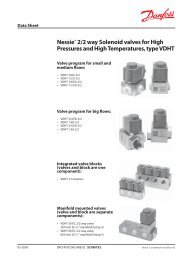
RADIALKOLBENPUMPENRADIAL PISTON PUMPSPOMPES À PISTONS RADIAUX<strong>RKP</strong><strong>EHV</strong>2135748961 Regelventil2 Wegaufnehmer3 Stellkolben4 Hubring5 Kolben mit Gleitschuh6 Kupplung7 Wälzlager8 Antriebswelle9 Gehäuse1 Servo solenoid valve2 Position transducer3 Control <strong>piston</strong>4 Stroke ring5 Piston with slipper pad6 Coupling7 Rolling bearing8 Drive shaft9 Body1 Servo-distributeurs2 Capteur de course3 Piston4 Bague de commande de cylindrée5 Piston avec patins6 Accouplement7 Roulement8 Arbre d’entainement9 Corps2 Moog <strong>RKP</strong>-<strong>EHV</strong>
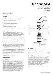
RADIALKOLBENPUMPENRADIAL PISTON PUMPSPOMPES À PISTONS RADIAUX<strong>RKP</strong><strong>EHV</strong>Wirkungsweise der <strong>Radial</strong>kolbenpumpeMode of operation of <strong>Radial</strong> <strong>piston</strong> <strong>pumps</strong>Fonctionnement de pompes à <strong>piston</strong> radiauxDas Antriebsmoment wird von der Welle(1) über eine Kreuzscheibenkupplung (2)querkraftfrei auf den Zylinderstern (3), derauf dem Steuerzapfen (4) gelagert ist,übertragen.Die radial im Zylinderstern angeordnetenKolben (5) stützen sich über hydrostatischentlastete Gleitschuhe (6) im Hubring (7)ab. Kolben und Gleitschuh sind über einKugelgelenk miteinander verbunden unddurch einen Ring gefesselt. Die Gleitschuhewerden durch zwei übergreifende Ringe(8) im Hubring geführt und im Betriebdurch Fliehkraft und Öldruck an den Hubringgedrückt. Bei Rotation des Zylindersternsführen die Kolben infolge der exzentrischenLage des Hubringes eine Hubbewegungaus, die dem doppelten Wertder Exzentrizität entspricht. Die Exzentrizitätwird durch zwei im Pumpengehäusegegenüberliegende Stellkolben (9, 10)verändert.Der Ölstrom wird über Kanäle in Gehäuseund Steuerzapfen zu- und abgeführt.Gesteuert wird dies mittels Saug- undDruckschlitz im Steuerzapfen.Die Abstützung der in der Pumpe auftretendenDruckkräfte erfolgt auf hydrostatischnahezu vollständig entlastetenFlächen.Das Wälzlager der Antriebswelle wird nurdurch äußere Kräfte belastet.The shaft (1) transfers the drive torque tothe star-shaped cylinder block (3) free fromany transverse forces via a cross-disc coupling(2). The cylinder block is supported onthe control journal (4).The radial <strong>piston</strong>s (5) in the cylinder blockabut against the stroke ring (7) throughhydrostatically balanced slipper pads (6).Piston and slipper pad are joined by a balland socket joint which is locked by a ring.The slipper pads are guided in the strokering by two overlapping rings (8) and,when running, are forced against thestroke ring by centrifugal force and oilpressure. As the cylinder block rotates, the<strong>piston</strong>s perform a reciprocating motiondue to the eccentric position of the strokering, the <strong>piston</strong> stroke being twice theeccentricity. The eccentric position of thestroke ring can be altered by means oftwo diametrically opposed control <strong>piston</strong>s(9, 10) in the pump body.The oil flow to and from the pump passesthrough ducts in the body and controljournal and is controlled by the suctionand delivery ports in the latter.The pressure forces generated inside thepump are absorbed by surfaces which arealmost fully hydrostatically balanced.The rolling bearing supporting the driveshaft is subjected to external forces only.Le couple d’entraînement est transmis sanscontraintes transversales de l’arbre (1) aubarillet à <strong>piston</strong>s radiaux (3) par l’intermédiaired’un accouplement à tenons (homocinétique)(2). Le barillet tourne autourd’un pivot de distribution (4).Les <strong>piston</strong>s (5) disposés de façon radialedans le barillet prennent appui par l’intermédiairede leur patin équilibré hydrostatiquement(6) sur la bague de commande decylindrée (7). Piston et patin sont articulésgrâce à une rotule et liés par une bague. Lespatins sont guidés sur la bague de commandede cylindrée par deux anneaux demaintien (8). Lors du fonctionnement, laforce centrifuge et la pression d’huile généréepar les <strong>piston</strong>s plaquent les patins sur labague de commande de cylindrée. La rotationdu barillet provoque le mouvementdes poistons qui effectuent une coursecorrespondant au double de l’excentricitéaffichée par la bague de commande decylindrée. L’excentricité de cette bague estmodifiée par un <strong>piston</strong> (9) et un contre<strong>piston</strong>(10) dans le corps de la pompe.Le débit d’huile arrive et part pas des canauxdisposés dans le corps en passant pardes haricots d’aspiration et de refoulementplacés sur le pivot de distribution.Toutes les forces apparaissant dans lapompe sont presque entièrement équilibréeshydrostatiquement.Le roulement de l’arbre d’entraînementsert uniquement à supporter les forcesextérieures.7 6!“42!≠ 3 5 9!¡8 14 Moog <strong>RKP</strong>-<strong>EHV</strong>
RADIALKOLBENPUMPENRADIAL PISTON PUMPSPOMPES À PISTONS RADIAUX<strong>RKP</strong><strong>EHV</strong>1. Allgemeines:Die elektrohydraulisch verstellbare<strong>Radial</strong>kolbenpumpe (<strong>RKP</strong>-<strong>EHV</strong>) lässt sichdirekt in Regelungen integrieren, die aufgrundder hohen geforderten Dynamikund Wiederholgenauigkeit bisher nurdurch den Einsatz von Regel- und Servoventilenzu verwirklichen waren.Damit lassen sich in vielen Fällen– qualitativ verbesserte– energiesparendere– kostengünstigereHydraulikaggregate und Maschinendarstellen.2. Programm– Sieben Baugrößen zwischen 19 und140 cm 3 /U (offener Kreis)– Mehrfachanordnung durch axialenAnbau von <strong>Radial</strong>kolben- oder Zahnradpumpenist der Antrieb mehrererPumpen über eine Welle möglich3. FunktionDie <strong>RKP</strong> mit elektrohydraulischer Verstellungist im Vergleich zu einer reinhydromechanisch geregelten <strong>RKP</strong> mit dreizusätzlichen Komponenten ausgestattet:– Lagemesssystem (11)– Regelventil (hochdynamisch) (12)– ElektronikverstärkerDamit lassen sich folgende Funktionenrealisieren:– Steuerung des Förderstroms:Der Förderstrom der Pumpe ist beikonstanter Antriebsdrehzahl proportionalzur Exzentrizität des Hubrings. DasZusammenspiel von Lagemesssystem,Elektronikverstärker und Regelventilermöglicht die genaue Regelung der Hubringpositionund damit die Steuerung desgewünschten Förderstroms.– Elektronische Druckregelung:Bei Erreichen des Druck-Sollwertes wirdder Volumenstrom der Pumpe so weitzurückgestellt, dass der vorgegebene Druckaufrechterhalten wird.– Leckölkompensation:Mit Hilfe einer elektrischen Schaltungin der Verstärkerelektronik können diedruckabhängigen volumetrischen Verlusteder Pumpe weitgehend ausgeglichenwerden.1. General informationThe radial <strong>piston</strong> pump with electric-hydrauliccontrol (<strong>RKP</strong>-<strong>EHV</strong>) can be integrated directlyinto control circuits which, up until now,could only be realized with servo solenoidvalves, due to the high dynamic demandsinvolved.This enables the design of hydraulic systemsand machines which are in many cases– of an improved quality– energy saving– less expensive2. Product range– Seven sizes available from 19 to 140 cm 3 /rev.(open circuit)– Multiple arrangement: several <strong>pumps</strong> canbe powered with a single shaft, thanks tothe axial mounting of radial <strong>piston</strong> or gear<strong>pumps</strong>.3. FunctionIn contrast to an <strong>RKP</strong> with purely hydraulicmechanicalcontrol, the electrically-controlled<strong>RKP</strong> is equipped with three additional components:– position-control measuring system (11)– servo solenoid valve (highly dynamic) (12)– electronic amplifierThe following functions can thus be realized:– Flow controlAt a constant drive speed the eccentricity ofthe stroke ring is proportional to the flow.The combination of position-control measuringsystem, electronic amplifier and servosolenoid valve enables accurate control ofthe stroke ring position and, consequently,control of the desired flow.– Electric pressure controlThe flow of the pump is reduced onreaching the pressure setpoint so that thespecified pressure is maintained.– Oil leakage compensationPressure-related volumetric losses in thepump are largely compensated for with theaid of an electric circuit in the amplifierelectronics.1. GénéralitésLa pompe à <strong>piston</strong> radial et à pilotage électrohydraulique(<strong>RKP</strong>-<strong>EHV</strong>) peut être intégrée directementdans les systèmes de régulation, ce qui,en raison des hautes exigences demandées à ladynamique et à la précision de répétition, n’étaitréalisable jusqu’ici qu’avec l’utilisation de servovalveset de vannes de régulation.Ce système permet de réaliser dans de nombreuxcas des machines et des agrégats hydrauliques– de meilleure qualité– plus économiques en énergie– moins onéreux.2. Programme– Sept tailles de construction différentes entre19 et 140 cm 3 /tr (circuit ouvert)– Disposition multiple: le montage axial depompes à <strong>piston</strong> radial ou à roues dentéespermet l’entraînement de plusieurs pompessur un arbre.3. FonctionnementLa <strong>RKP</strong> à pilotage électro-hydraulique est, comparéeà une <strong>RKP</strong> à pilotage purement hydromécanique,équipée de trois composants supplémentaires:– un système de mesure de la position (11)– une vanne de régulation (hautement dynamique)(12)– un amplificateur électroniqueCe qui permet de réaliser les fonctions suivantes :– Commande du débit:L’excentricité de la bague de commande estproportionnelle au débit de la pompe lorsquela vitesse d’entraînement est constante. Le jeud’ensemble de système de mesure de la position,amplificateur électronique et vanne derégulation permettent la régulation précise dela position de la couronne de levage et donc lacommande du débit souhaité.– Régulation électronique de la pression:Lorsque la pression a atteint sa valeur de consigne,le courant volumique de la pompe estalors diminué juste assez pour maintenir lapression existante.– Compensation de l’huile de fuite:Grâce à une commutation électrique installéedans le système électronique d’amplification,vous pouvez compenser de façon notable lespertes volumétriques de la pompe qui dépendentde la pression.Moog <strong>RKP</strong>-<strong>EHV</strong> 5
RADIALKOLBENPUMPENRADIAL PISTON PUMPSPOMPES À PISTONS RADIAUX<strong>RKP</strong><strong>EHV</strong>Regelung:Die Exzentrizität des Hubrings wird direktam Stellkolben von einem druckdichten,elektronischen Wegaufnehmer gemessen.Ein Elektronikverstärker vergleicht dasSignal des Wegaufnehmers mit dem vorgegebenenSollwertsignal. Entsprechend derAbweichung lenkt er das Regelventil zurVerstellung des Hubrings aus. Die Funktionsweiseist sinngemäß vergleichbar mitder eines zweistufigen Proportional- oderRegelventils. Die Bauart des Vorsteuerventilsist identisch. Jedoch anstelle desHauptsteuerschiebers wirkt hier der Hubring.Verstellt wird der Hubring über zweiKolben, die gegenüberliegend im Gehäuseder Pumpe angeordnet sind. Über dieAnsteuerung durch das Regelventil wirdeine stufenlose Anpassung des Hubs derPumpenkolben und damit eine Veränderungdes Förderstroms erreicht.4. Vorteile gegenüber der Lösung mitmechanischem Druck-Förderstromregler– Kürzere Stellzeiten bei niedrigemSystemdruck, besonders beiFremddruckversorgung der Verstellung.– Lineare Druckkennlinie bis zu niedrigenDruckeinstellwerten. Somit Erzielunghoher Genauigkeiten der eingestelltenDruckwerte auch in niederen Druckbereichen.– Besserer SystemwirkungsgradBei hydromechanisch stromgeregeltenSystemen ist die Verlustleistung proportionalzum Volumenstrom (P V ~dp*Q).Dieser systembedingte Verlust entfällt.Control:The eccentricity of the stroke ring is measureddirectly at the control <strong>piston</strong> bymeans of an electronic, pressure-tight positiontransducer. An electronic amplifiercompares the signal from the positiontransducer with the specified setpointsignal. It deflects the servo solenoid forcontrolling the stroke ring according to theextent of deviation. Its function is equivalentto that of a two-stage proportional orservo solenoid valve. The pilot valve isidentical. However, the stroke ring takesthe place of the main control spool here.The stroke ring is controlled by means oftwo diametrically-opposed <strong>piston</strong>s in thepump body. Activation of the servo solenoidvalve enables the <strong>piston</strong> pump to beinfinitely adjusted, thus changing the displacement.4. Advantages compared with mechanicalpressure / flow compensator– Shorter response times at low systempressure, especially when the control issupplied with external pressure.– Linear pressure performance curve indicatingeven low pressure setting values.This enables the achievement of highlyaccurate set pressure values.– Improved system efficiencyThe power lost in hydraulic-mechanicalsystems with flow control is proportionalto the flow rate (P V ~dp*Q).These system-inherent losses areeliminated.Régulation:L’excentricité de la couronne de levage estdirectement mesurée sur le <strong>piston</strong> de réglagepar un capteur électronique du déplacement,étanche à la pression. Un amplificateurélectronique compare le signal ducapteur du déplacement avec le signal deconsigne donné. En fonction de l’écart, ilagit sur la vanne de régulation en sorted’ajuster la couronne de levage. Le modede fonctionnement est comparable à celuid’une vanne proportionnelle ou de régulationà deux paliers. Le type de constructionde la soupape pilote est identique. Toutefois,à la place de la vanne pilote principale,c’est la couronne de levage qui entreici en action. Cette couronne de levage estdéplacée par deux <strong>piston</strong>s disposés face àface dans le carter de la pompe. L’adaptationen continu de la course du <strong>piston</strong> depompe, et donc la modification du débit,sont obtenues par la commande de lavanne de régulation.4. Les avantages par rapport à la solutionavec le régulateur mécanique de pression– débit.– Des temps de réglage plus courts lorsd’une basse pression de système, particulièrementdans le cas d’une alimentationexterne en pression du systèmede réglage.– Linéarité de la ligne caractéristique depression jusqu’aux basses valeurs deréglage de la pression, ce qui permetd’obtenir une grande haute précisiondes valeurs de pression réglées, et ce,même dans des plages de basse pression.– Un meilleur degré d’action du système.Pour les systèmes à régulation hydromécaniquedu débit, la puissance deperte est proportionnelle au débitvolumique (P V ~dp*Q), cette perte dueau système disparaît.6 Moog <strong>RKP</strong>-<strong>EHV</strong>
RADIALKOLBENPUMPENRADIAL PISTON PUMPSPOMPES À PISTONS RADIAUX<strong>RKP</strong><strong>EHV</strong>Pos. Sym. <strong>Radial</strong>kolbenpumpe <strong>Radial</strong> <strong>piston</strong> pump Pompe à <strong>piston</strong>s radiaux6 Arbeitsprinzip Operating principle Principe technologiqueR <strong>Radial</strong>kolbenprinzip <strong>Radial</strong> <strong>piston</strong> principle Principe à <strong>piston</strong>s radiaux7 Betriebsart Mode of operation Mode de fonctionnementP Pumpenbetrieb Pump Pompe8 Bauart Type of construction Type de fonctionnementV Verstellpumpe (offener Kreis) Displacement pump (open circuit) Cylindrée variable (circuit ouvert)9 Fördervolumen Displacement Cylindrée19 19 cm 3 /U 19 cm 3 /rev 19 cm 3 /t32 32 cm 3 /U 32 cm 3 /rev 32 cm 3 /t45 45 cm 3 /U 45 cm 3 /rev 45 cm 3 /t63 63 cm 3 /U 63 cm 3 /rev 63 cm 3 /t80 80 cm 3 /U 80 cm 3 /rev 80 cm 3 /t100 100 cm 3 /U 100 cm 3 /rev 100 cm 3 /t140 140 cm 3 /U 140 cm 3 /rev 140 cm 3 /t10 Gehäuseausführung Housing version Modèle de corpsS Saug- und Druckanschluss mit Suction and pressure connec- Raccord d’aspiration et de pres-Flansch SAE 3000 psi (bis 280 bar) tion with flange SAE 3000 psi sion avec flasque SAE 3000 psi(up to 280 bar)(jusqu’à 280 bar)S/H Sauganschluss mit Flansch nur <strong>RKP</strong> Suction connection with only <strong>RKP</strong> Raccord d’aspiration avec seulementSAE 3000 psi flange SAE 3000 psi flasque SAE 3000 psi<strong>RKP</strong>Druckanschluss mit Flansch 100Pressure connection with 100Raccord de pression avec 100SAE 6000 psi 140flange SAE 6000 psi 140flasque SAE 6000 psi14011 Betriebsflüssigkeit Operating fluid Fluide utiliséM Mineralöl Mineral oil Huile minéraleC HFC HFC HFC12 Betriebsdruck Operating pressure Pression de service28 Max. Betriebsdruck, Max. operating pressure, Pression max. de service,z.B. p = 280 bar 28 e.g. p = 280 bar 28 par ex. p = 280 bar 2813 Steuerung/Regler Control Commande/régulateur V [cm 3 ]B Mech. Hubeinstellung Mech. stroke adjustment Ajustage mécanique de 19 32 45 63 80 100 140 BZ(V = const.) (V = const.) la course (V = const.)T Elektrohydraulische Electric-hydraulic Commande électro- 19 32 45 63 80 100 140 TZ TYVerstellung control hydraulique14 Zusatzeinrichtung Accessories Dispositif additionnelZ ohne Zusatzeinrichtung No accessories Sans dispositif additionnelY Begrenz. max. Förderstroms Limiting of max. flow Avec limitation de débit15 * Zusatzangabe Additional information Donnée complémentaireElektrohydraulische Verstellung T Electric-hydraulic control T Commande électrohydraulique T1 Ansteuerung durch Eigendruck Actuation by means of internal pressure Pilotage par pression interne2 Ansteuerung durch Fremddruck Actuation by means of external pressure Pilotage par pression externe Nicht lieferbarNot availableNon disponibleMoog <strong>RKP</strong>-<strong>EHV</strong> 13
RADIALKOLBENPUMPENRADIAL PISTON PUMPSPOMPES À PISTONS RADIAUX<strong>RKP</strong><strong>EHV</strong>Pos. Sym. Zahnradpumpe Gear pump Pompe à engrenage6 Arbeitsprinzip Operating principle Principe technologiqueZ Zahnradprinzip Gear wheel principle Principe à engrenage7 Betriebsart Mode of operation Mode de fonctionnementP Pumpenbetrieb Pump Pompe8 Bauart Type of construction Type de fonctionnementN Buchsenbauart, Normalausführung Bushes-type, standard version Paliers flottants, exécution standard9 Fördervolumen Displacement CylindréeBaugröße Baugröße Size Size Taille Taille„F“ „G“ “F” “G” «F» «G»4 4 cm 3 /U 4 cm 3 /rev 4 cm 3 /t5 5,5 cm 3 /U 5.5 cm 3 /rev 5,5 cm 3 /t8 8 cm 3 /U 8 cm 3 /rev 8 cm 3 /t11 11 cm 3 /U 11 cm 3 /rev 11 cm 3 /t16 16 cm 3 /U 16 cm 3 /rev 16 cm 3 /t19 19 cm 3 /U 19 cm 3 /rev 19 cm 3 /t22 22,5 cm 3 /U Anbau 22.5 cm 3 /rev Mounting 22,5 cm 3 /tMontage32 32 cm 3 /U 32 cm 3 /rev 32 cm 3 /t sur <strong>RKP</strong>45 45 cm 3 /U 32 bis 14045 cm 3 /rev 32 to 14045 cm 3 /t 32 à 14010 Gehäuseausführung Housing version Modèle de corpsB Leitungsanschluss Bosch Bosch line connection Raccordement Bosch11 Betriebsflüssigkeit Operating fluid Fluide utiliséM Mineralöl Mineral oil Huile minéraleC HFC (nur für Baugröße „F“) HFC (size “F” only) HFC (seulement taille «F»)12 Betriebsdruck Operating pressure Pression de service18 Max. Betriebsdruck, Max. operating pressure, Pression max. de service,z.B. p = 175 bar 18 e.g. p = 175 bar 18 par ex. p = 175 bar 1813 Baugröße Size TailleF Baugröße „F“ Size “F” Taille «F»G Baugröße „G“ Size “G” Taille «G»14 Zusatzeinrichtung Accessories Dispositif additionnelZ ohne Zusatzeinrichtung No accessories Sans dispositif additionnel15 Zusatzangabe Additional information Donnée complémentaire00 ohne Zusatzangabe No additional information Sans donnée complémentaireFett gedruckte Positionen sind bevorzugt lieferbar.Items in bold-face type are preferred delivery items.Les positions imprimées en caractères gras sont disponibles plus rapidement.14 Moog <strong>RKP</strong>-<strong>EHV</strong>
RADIALKOLBENPUMPENRADIAL PISTON PUMPSPOMPES À PISTONS RADIAUX<strong>RKP</strong><strong>EHV</strong>KENNGRÖSSENFördervolumen [cm 3 /U] 19 32 45 63 80 100 140BauartPumpe für offenen Kreis mit verschiedenen Verstell- und RegeleinrichtungenBefestigungsart 1. Stirnbefestigung, Zentrier- und Lochkreisdurchmesser nach DIN/ISO 3019/22. Anbauflansch nach DIN/ISO 3019/13. Anbauflansch nach DIN/ISO 3019/2EinbaulagebeliebigMasse [kg] 22 33 33 65 65 71 105Massenträgheitsmoment [kg cm 2 ] 17,7 61,0 61,0 186,3 186,3 186,3 380,0LeitungsanschlussStandardausführung 3 / 4″ 1″ 1″ 1 1 / 4″ 1 1 / 4″ 1 1 / 2″ 2 1 / 2″SAE 3000 psi (Saug) (Saug)1 1 / 4″ 1 1 / 2″(Druck) (Druck)SAE SAE6000 psi 6000 psiEmpfohlener Rohraußendurch- 15 18 18 22 22 22 22messer für Leckstromleitungen(leichte Baureihe) [mm]LeckstromabführungDie Leckstromleitung ist so zu verlegen, dass das Pumpengehäuse stets vollständigmit Druckflüssigkeit gefüllt ist. Der Druck am Leckstromanschluss darf 2 bar absolut(1 bar Überdruck) nicht überschreiten. Leitungsende unterhalb des Flüssigkeitsspiegels.Kein Filter und kein Rückschlagventil in die Leckstromleitung.AntriebsartDirektantrieb mit Kupplung (bei anderer Antriebsart bitte Rücksprache)Umgebungstemperaturbereich –15 °C bis +60 °CMax. Drehzahl bei Eingangsdruck 2700 2500 1800 2100 1500 1500 15000,8 bar abs. [min –1 ]Max. Drehzahl bei Eingangsdruck 2900 2900 2100 2300 1800 1800 18001 bar abs. [min –1 ]Höchstdrehzahl für geräusch- 1800 1800 1800 1800 1800 1800 1800armen Lauf [min –1 ]Min. Eingangsdruck0,8 bar (absolut)SauganschlussMax. Gehäusedruck2 bar (1 bar Überdruck)Standard- Dauerdruck 280 280 280 280 280 280 280ausführung Höchstdruck 1 ) [bar] 300 300 300 300 300 300 300S Druckspitze 330 330 330 330 330 330 330Druckflüssigkeit Mineralöl nach DIN 51 524Druckflüssigkeitstemperaturbereich –15 °C bis +80 °CViskositätZulässiger Betriebsbereich 12 bis 100 mm 2 /s;empfohlene Viskosität der Druckflüssigkeit 46 mm 2 /s bei +40 °C (ISO-VG 46);max. Viskosität 500 mm 2 /s während des Anlaufs mit Elektromotor 1800 min –1 ;max. Viskosität 800 mm 2 /s während des Anlaufs mit VerbrennungsmotorFilterung NAS 1638, Klasse 9;ISO/DIS 4406, Klasse 18/15Zu erreichen mit Filterfeinheit 20 = 75 2 )1 ) Höchstdruck nach DIN 24 3122 ) Rückhalterate für Schmutzteilchen > 20 µm ist 1: 75, d.h. 98,67 % WarnungInbetriebnahme der Pumpen muss durch entsprechend ausgebildetes Fachpersonal erfolgen.Die Öltemperatur im Tank darf die Temperatur der Pumpe nicht mehr als 25 °C übersteigen. Ist dies der Fall, so darf die Pumpe bis zur Erwärmungnur in kurzen Intervallen von ca. 1…2 Sekunden eingeschaltet werden.Weitere Angaben siehe Betriebsanleitung.Moog <strong>RKP</strong>-<strong>EHV</strong> 15
RADIALKOLBENPUMPENRADIAL PISTON PUMPSPOMPES À PISTONS RADIAUX<strong>RKP</strong><strong>EHV</strong>SPECIFICATIONSDisplacement [cm 3 /rev] 19 32 45 63 80 100 140Type of constructionPump for open circuit with various control devicesType of mounting 1. End mounting, centering and hole-circle dia. to DIN/ISO 3019/22. Mounting flange to DIN/ISO 3019/13. Mounting flange to DIN/ISO 3019/2Mounting positionoptionalWeigth [kg] 22 33 33 65 65 71 105Mass moment of inertia [kg cm 2 ] 17.7 61.0 61.0 186.3 186.3 186.3 380.0Line connectionStandard version 3 / 4″ 1″ 1″ 1 1 / 4″ 1 1 / 4″ 1 1 / 2″ 2 1 / 2″SAE 3000 psi (suction) (suction)1 1 / 4″ 1 1 / 2″(pressure) (pressure)SAE SAE6000 psi 6000 psiRecommended pipe OD 15 18 18 22 22 22 22for drain lines(lightweight version) [mm]DrainThe drain line has to be routed so that the pump housing is always completely filledwith pressure fluid. The pressure at the drain port must not exeed 2 bar(1 bar gauge pressure). End of line beneath fluid level.No filter or non-return valve in the drain line.Type of driveDirect drive with coupling (please enquire for other types)Ambient temperature range –15 °C to +60 °CMax. speed at inlet pressure 2700 2500 1800 2100 1500 1500 15000.8 bar abs. [min –1 ]Max. peed at inlet pressure 2900 2900 2100 2300 1800 1800 18001 bar abs. [min –1 ]Maximum speed for silent 1800 1800 1800 1800 1800 1800 1800running [min –1 ]Min. inlet pressure,0.8 bar (absolute)suction connectionMax. housing pressure2 bar (1 bar gauge pressure)Standard continuous pressure 280 280 280 280 280 280 280version max. pressure 1 ) [bar] 300 300 300 300 300 300 300S pressure peak 330 330 330 330 330 330 330Hydraulic fluid Mineral oil to DIN 51 524Hydraulic fluid temperature range –15 °C to +80 °CViscosityAllowable operational range 12 to 100 mm 2 /s;recommended viscosity of fluid 46 mm 2 /s at +40 °C (ISO-VG 46);max. viscosity 500 mm 2 /s during start-up with electric motor 1800 min –1 ;max. viscosity 800 mm 2 /s during start-up with internal combustion engineFiltering NAS 1638, class 9;ISO/DIS 4406, class 18/15Obtained with filter fineness 20 = 75 2 )1 ) Max. pressure to DIN 24 3122 ) Dirt particles retention rate > 20 µm is 1: 75, i.e. 98.67 % WarningPumps may only be put into operation by appropriately trained qualified personnel.The oil temperature in the tank may not exceed the pump temperature by more than 25 °C. Should this occur, then thepump may be switched on only in short intervals of approx. 1–2 seconds until it has warmed up.For further information please see Instruction Manual.16 Moog <strong>RKP</strong>-<strong>EHV</strong>
RADIALKOLBENPUMPENRADIAL PISTON PUMPSPOMPES À PISTONS RADIAUX<strong>RKP</strong><strong>EHV</strong>CARACTÉRISTIQUESCylindrée [cm 3 /t] 19 32 45 63 80 100 140ConstructionPompe pour circuit ouvert avec différents modes de réglage et régulationMode de fixation 1. Fixation frontale, diamètre de centrage et de perçage selon DIN/ISO 3019/22. Flasque de montage selon DIN/ISO 3019/13. Flasque de montage selon DIN/ISO 3019/2Position de montageindifférenteMasse [kg] 22 33 33 65 65 71 105Moment d’inertie de masse [kg cm 2 ] 17,7 61,0 61,0 186,3 186,3 186,3 380,0Orifice de la conduiteExécution standard 3 / 4″ 1″ 1″ 1 1 / 4″ 1 1 / 4″ 1 1 / 2″ 2 1 / 2″SAE 3000 psi (aspiration) (aspiration)1 1 / 4″ 1 1 / 2″(pression) (pression)SAE SAE6000 psi 6000 psiDiamètre extérieur de tuyau 15 18 18 22 22 22 22recommandé pour les conduitesde fuite (gamme légère) [mm]Evacuation du fluide de fuiteLa conduite de fuite est disposée de manière à ce que le niveau du fluide dans lecarter de la pompe reste à son maximum. La pression à l’orifice de fuite ne doit pasdépasser 2 bar (pression relative 1 bar). Extrémités de la conduite en dessous duniveau du fluide. Pas de filtre et pas de clapet anti-retour dans la conduite de fuite.Mode d’entraînementEntraînement direct avec accouplement (pour d’autres montages, nous consulter)Plage de température ambiante –15 °C à +60 °CVitesse de rotation maximale à 2700 2500 1800 2100 1500 1500 1500pression d’entrée 0,8 bar abs. [min –1 ]Vitesse de rotation maximale à 2900 2900 2100 2300 1800 1800 1800pression d’entrée 1 bar abs. [min –1 ]Vitesse de rotation maximale pour un 1800 1800 1800 1800 1800 1800 1800niveau sonore minimal [min –1 ]Pression d’entrée min.,0,8 bar (valeur absolue)orifice d’aspirationPression max. dans le corps2 bar (surpression 1 bar)Exécution pression permanente 280 280 280 280 280 280 280standard pression max. 1 ) [bar] 300 300 300 300 300 300 300S pointe de pression 330 330 330 330 330 330 330Fluide hydraulique Huile minérale selon DIN 51 524Plage de température du fluide –15 °C à +80 °CViscositéPlage admissible 12 à 100 mm 2 /s;viscosité conseillée 46 mm 2 /s à +40 °C (ISO-VG 46);viscosité max. 500 mm 2 /s durant la phase de démarrage avec moteurélectrique 1800 min –1 ;viscosité max. 800 mm 2 /s durant la phase de démarrage avec moteur àcombustion interneFiltration NAS 1638, classe 9;ISO/DIS 4406, classe 18/15Par emploi d’un filtre 20 = 75 2 )1 ) Pression max. selon DIN 24 3122 ) Taux de retenue des impuretés > 20 µm est 1: 75, c’est-à-dire 98,67 % AvertissementLa mise en service doit être effectuée par du personnel qualifié, formé en conséquence.La température de l’huile dans le réservoir ne doit pas dépasser que la température de la pompe de plus de 25 °C. Si cette condition n’est pasremplie, la pompe ne doit être enclenchée que durant de courtes périodes de 1 à 2 secondes environ jusqu’à son réchauffement.Autres indications, voir Notice d’utilisation.Moog <strong>RKP</strong>-<strong>EHV</strong> 17
<strong>RKP</strong> 19<strong>RKP</strong><strong>EHV</strong>V = 19 cm 3 /UElektrohydraulische Verstellung TStandardausführung SNormale Lagerung,Stirnbefestigung A1V = 19 cm 3 /revElectric-hydraulic control TStandard version SStandard bearing arrangement,metric mounting flange A1V = 19 cm 3 /tCommande électro-hydraulique TExécution standard SPalier normal, flasque de montageaux cotes métriques A1Moog <strong>RKP</strong>-<strong>EHV</strong> 18
<strong>RKP</strong> 19<strong>RKP</strong><strong>EHV</strong>Nnwie in Zeichnung dargestelltas shown in drawingcomme montré sur dessinSaug- und Druckanschluss vertauschtSuction and pressure connection interchangedRaccords d’aspiration et de pression intervertis VorsichtDrehrichtungswechsel nicht möglich CautionChange of rotation not possible AttentionChangement de rotation impossibleMoog <strong>RKP</strong>-<strong>EHV</strong> 19
<strong>RKP</strong> 19<strong>RKP</strong><strong>EHV</strong>V = 19 cm 3 /UElektrohydraulische Verstellung TStandardausführung SNormale Lagerung, Anbauflansch nachDIN/ISO 3019/1 C 3V = 19 cm 3 /revElectric-hydraulic control TStandard version SStandard bearing arrangement,mounting flange toDIN/ISO 3019/1 C 3V = 19 cm 3 /tCommande électro-hydraulique TExécution standard SPalier normal, flasque de montageselon DIN/ISO 3019/1 C 320 Moog <strong>RKP</strong>-<strong>EHV</strong>
<strong>RKP</strong> 19<strong>RKP</strong><strong>EHV</strong>Nnwie in Zeichnung dargestelltas shown in drawingcomme montré sur dessinSaug- und Druckanschluss vertauschtSuction and pressure connection interchangedRaccords d’aspiration et de pression intervertis VorsichtDrehrichtungswechsel nicht möglich CautionChange of rotation not possible AttentionChangement de rotation impossibleMoog <strong>RKP</strong>-<strong>EHV</strong> 21
<strong>RKP</strong> 32/45<strong>RKP</strong><strong>EHV</strong>Nnwie in Zeichnung dargestelltas shown in drawingcomme montré sur dessinSaug- und Druckanschluss vertauschtSuction and pressure connection interchangedRaccords d’aspiration et de pression intervertis VorsichtDrehrichtungswechsel nicht möglich CautionChange of rotation not possible AttentionChangement de rotation impossibleMoog <strong>RKP</strong>-<strong>EHV</strong> 23
<strong>RKP</strong> 32/45<strong>RKP</strong><strong>EHV</strong>V = 32 und 45 cm 3 /UElektrohydraulische Verstellung TStandardausführung SNormale Lagerung, Anbauflansch nachDIN/ISO 3019/1 C 3V = 32 and 45 cm 3 /revElectric-hydraulic control TStandard version SStandard bearing arrangement,mounting flange toDIN/ISO 3019/1 C 3V = 32 et 45 cm 3 /tCommande électro-hydraulique TExécution standard SPalier normal, flasque de montageselon DIN/ISO 3019/1 C 324 Moog <strong>RKP</strong>-<strong>EHV</strong>
<strong>RKP</strong> 32/45<strong>RKP</strong><strong>EHV</strong>Nnwie in Zeichnung dargestelltas shown in drawingcomme montré sur dessinSaug- und Druckanschluss vertauschtSuction and pressure connection interchangedRaccords d’aspiration et de pression intervertis VorsichtDrehrichtungswechsel nicht möglich CautionChange of rotation not possible AttentionChangement de rotation impossibleMoog <strong>RKP</strong>-<strong>EHV</strong> 25
<strong>RKP</strong> 32/45<strong>RKP</strong><strong>EHV</strong>V = 63 und 80 cm 3 /UElektrohydraulische Verstellung TStandardausführung SNormale Lagerung,Stirnbefestigung A1V = 63 and 80 cm 3 /revElectric-hydraulic control TStandard version SStandard bearing arrangement,metric mounting flange A1V = 63 et 80 cm 3 /tCommande électro-hydraulique TExécution standard SPalier normal, flasque de montageaux cotes métriques A126 Moog <strong>RKP</strong>-<strong>EHV</strong>
<strong>RKP</strong> 32/45<strong>RKP</strong><strong>EHV</strong>Nnwie in Zeichnung dargestelltas shown in drawingcomme montré sur dessinSaug- und Druckanschluss vertauschtSuction and pressure connection interchangedRaccords d’aspiration et de pression intervertis VorsichtDrehrichtungswechsel nicht möglich CautionChange of rotation not possible AttentionChangement de rotation impossibleMoog <strong>RKP</strong>-<strong>EHV</strong> 27
<strong>RKP</strong> 63/80<strong>RKP</strong><strong>EHV</strong>V = 63 und 80 cm 3 /UElektrohydraulische Verstellung TStandardausführung SNormale Lagerung, Anbauflansch nachDIN/ISO 3019/1 C 3V = 63 and 80 cm 3 /revElectric-hydraulic control TStandard version SStandard bearing arrangement,mounting flange toDIN/ISO 3019/1 C 3V =63 et 80 cm 3 /tCommande électro-hydraulique TExécution standard SPalier normal, flasque de montageselon DIN/ISO 3019/1 C 328 Moog <strong>RKP</strong>-<strong>EHV</strong>
<strong>RKP</strong> 63/80<strong>RKP</strong><strong>EHV</strong>Nnwie in Zeichnung dargestelltas shown in drawingcomme montré sur dessinSaug- und Druckanschluss vertauschtSuction and pressure connection interchangedRaccords d’aspiration et de pression intervertis VorsichtDrehrichtungswechsel nicht möglich CautionChange of rotation not possible AttentionChangement de rotation impossibleMoog <strong>RKP</strong>-<strong>EHV</strong> 29
<strong>RKP</strong> 100<strong>RKP</strong><strong>EHV</strong>V = 100 cm 3 /UElektrohydraulische Verstellung TStandardausführung S/HNormale Lagerung,Stirnbefestigung A1V = 100 cm 3 /revElectric-hydraulic control TStandard version S/HStandard bearing arrangement,metric mounting flange A1V = 100 cm 3 /tCommande électro-hydraulique TExécution standard S/HPalier normal, flasque de montageaux cotes métriques A130 Moog <strong>RKP</strong>-<strong>EHV</strong>
<strong>RKP</strong> 100<strong>RKP</strong><strong>EHV</strong>Nnwie in Zeichnung dargestelltas shown in drawingcomme montré sur dessinSaug- und Druckanschluss vertauschtSuction and pressure connection interchangedRaccords d’aspiration et de pression intervertis VorsichtDrehrichtungswechsel nicht möglich CautionChange of rotation not possible AttentionChangement de rotation impossibleMoog <strong>RKP</strong>-<strong>EHV</strong> 31
<strong>RKP</strong> 100<strong>RKP</strong><strong>EHV</strong>V = 100 cm 3 /UElektrohydraulische Verstellung TStandardausführung S/HNormale Lagerung, Anbauflanschnach DIN/ISO 3019/1 C 3V = 100 cm 3 /revElectric-hydraulic control TStandard version S/HStandard bearing arrangement,mounting flange toDIN/ISO 3019/1 C 3V = 100 cm 3 /tCommande électro-hydraulique TExécution standard S/HPalier normal, flasque de montageselon DIN/ISO 3019/1 C 332 Moog <strong>RKP</strong>-<strong>EHV</strong>
<strong>RKP</strong> 100<strong>RKP</strong><strong>EHV</strong>Nnwie in Zeichnung dargestelltas shown in drawingcomme montré sur dessinSaug- und Druckanschluss vertauschtSuction and pressure connection interchangedRaccords d’aspiration et de pression intervertis VorsichtDrehrichtungswechsel nicht möglich CautionChange of rotation not possible AttentionChangement de rotation impossibleMoog <strong>RKP</strong>-<strong>EHV</strong> 33
<strong>RKP</strong> 140<strong>RKP</strong><strong>EHV</strong>V = 140 cm 3 /UElektrohydraulische Verstellung TStandardausführung S/HNormale Lagerung, Anbauflanschnach DIN/ISO 3019/2 A7V = 140 cm 3 /revElectric-hydraulic control TStandard version S/HStandard bearing arrangement,mounting flange to DIN/ISO 3019/2 A7V = 140 cm 3 /tCommande électro-hydraulique TExécution standard S/HPalier normal, flasque de montageselon DIN/ISO 3019/2 A734 Moog <strong>RKP</strong>-<strong>EHV</strong>
<strong>RKP</strong> 140<strong>RKP</strong><strong>EHV</strong>Nnwie in Zeichnung dargestelltas shown in drawingcomme montré sur dessinSaug- und Druckanschluss vertauschtSuction and pressure connection interchangedRaccords d’aspiration et de pression intervertis VorsichtDrehrichtungswechsel nicht möglich CautionChange of rotation not possible AttentionChangement de rotation impossibleMoog <strong>RKP</strong>-<strong>EHV</strong> 35
<strong>RKP</strong> 140<strong>RKP</strong><strong>EHV</strong>V = 140 cm 3 /UElektrohydraulische Verstellung TStandardausführung S/HNormale Lagerung, Anbauflanschnach DIN/ISO 3019/1 C 3V = 140 cm 3 /revElectric-hydraulic control TStandard version S/HStandard bearing arrangement,mounting flange to DIN/ISO 3019/1 C 3V = 140 cm 3 /tCommande électro-hydraulique TExécution standard S/HPalier normal, flasque de montageselon DIN/ISO 3019/1 C 336 Moog <strong>RKP</strong>-<strong>EHV</strong>
<strong>RKP</strong> 140<strong>RKP</strong><strong>EHV</strong>Nnwie in Zeichnung dargestelltas shown in drawingcomme montré sur dessinSaug- und Druckanschluss vertauschtSuction and pressure connection interchangedRaccords d’aspiration et de pression intervertis VorsichtDrehrichtungswechsel nicht möglich CautionChange of rotation not possible AttentionChangement de rotation impossibleMoog <strong>RKP</strong>-<strong>EHV</strong> 37
VORSPANNBLÖCKEPRESSURE-SEQUENCE BLOCKSBLOC DE PRÉCONTRAINTE<strong>RKP</strong><strong>EHV</strong>Vorspannblöcke bei eigendruckangesteuerten<strong>RKP</strong>-<strong>EHV</strong> (Regler T1) ermöglichen einehohe Dynamik und einen sicheren Betriebbei niedrigen Systemdrücken.Fällt der Systemdruck unter den Minimaldruckder Pumpe, so hält das Vorspannventilam Pumpenausgang einen Minimaldruckvon 16 bar. Der Systemdruck hinterdem Vorspannventil kann bis auf 0 bargeregelt werden.Oberhalb seines Öffnungsdrucks ist dasVorspannventil (C1.0) geöffnet und bewirktnur geringe Drosselverluste. Nebendem Vorspannventil (C1.0) enthält derkleine Vorspannblock, der am Druckanschlussder Pumpe montiert wird, einSicherheitsventil (C3.0) für das System,ein Rückschlagventil (C2.0) für den Druckabbausowie die Anschlussmöglichkeiteines Drucksensors (X1.1 oder X1.2).Pressure sequence blocks for <strong>RKP</strong>-<strong>EHV</strong>(controller T1) with internal-pressure activationenable the achievement of a highdynamic level and safe operation at lowsystem pressures.The pressure sequence valve on the pumpoutlet maintains a minimum pressure of16 bar if the system pressure falls belowthe minimum pump pressure. The systempressure below the minimum pump pressurecan be controlled down to 0 bar.The pressure sequence valve (C1.0) is openedon exceeding its own opening pressureand causes only slight throttling loss.In addition to the pressure sequence valve(C1.0), the small pressure sequence blockmounted on the pump pressure connectioncontains a relief valve (C3.0) for the system,a non-return valve (C2.0) for pressure reliefand a connection for a pressure sensor(X1.1 or X1.2).Pour les pompes <strong>RKP</strong>-<strong>EHV</strong> à pression autonome(régulateur T1), les blocs de précontraintepermettent une haute dynamiqueet un fonctionnement en toute sécuritéavec de faibles pressions de système.Si la pression du système chute en dessousde la pression minimale de la pompe, lavanne de précontrainte maintient unepression minimale de 16 bar à la sortie dela pompe. La pression du système derrièrela vanne de précontrainte peut être réguléejusqu’à 0 bar.Au delà de sa pression d’ouverture, lavanne de précontrainte (C1.0) est ouverteet entraîne de faibles pertes d’étranglementseulement.A côté de la vanne de précontrainte (C1.0),le petit bloc de précontrainte, qui estmonté sur l’orifice de pression de lapompe, contient une soupape de sûreté(C3.0) pour le système, un clapet anti-retour(C2.0) pour la réduction de la pression,et la possibilité de brancher un capteur depression (X1.1 ou X1.2)C1.0C3.0C2.0PumpePumpPompe38 Moog <strong>RKP</strong>-<strong>EHV</strong>
VORSPANNBLÖCKEPRESSURE-SEQUENCE BLOCKSBLOC DE PRÉCONTRAINTE<strong>RKP</strong><strong>EHV</strong>fürforde <strong>RKP</strong>194xInnensechskantschraubensocket screwsvis à six pans creux ISO 4762-M 10 x 155 – 12.9Anzugsmoment:Tightening torque:Couple de serrage:M = 50 NmSAE 3/4″ – 3000 PSI4x Ø 10,5 mmFördervolumen Druckbereich Gewicht BestellnummerDisplacement Pressure range Weight Ordering codeCylindrée Plage de pression Poids Référence19 cm 3 /(U, rev, t) 30...350 bar 10 kg XEB 17642-000-01Moog <strong>RKP</strong>-<strong>EHV</strong> 39
VORSPANNBLÖCKEPRESSURE-SEQUENCE BLOCKSBLOC DE PRÉCONTRAINTE<strong>RKP</strong><strong>EHV</strong>fürforde <strong>RKP</strong>32 und 454xInnensechskantschraubensocket screwsvis à six pans creux ISO 4762-M 10 x 155 – 12.9Anzugsmoment:Tightening torque:Couple de serrage:M = 50 NmFl. SAE 1” – 3000 PSI4x Ø 10,5 mmFördervolumen Druckbereich Gewicht BestellnummerDisplacement Pressure range Weight Ordering codeCylindrée Plage de pression Poids Référence32, 45 cm 3 /(U, rev, t) 30...350 bar 10 kg XEB 17643-000-0140 Moog <strong>RKP</strong>-<strong>EHV</strong>
VORSPANNBLÖCKEPRESSURE-SEQUENCE BLOCKSBLOC DE PRÉCONTRAINTE<strong>RKP</strong><strong>EHV</strong>fürforde <strong>RKP</strong>63 und 804xInnensechskantschraubensocket screwsvis à six pans creux ISO 4762-M 12 x 160 – 12.9Anzugsmoment:Tightening torque:Couple de serrage:M = 100 NmFl. SAE 1 1 /4” – 3000 PSI4x Ø 13,5 mmFördervolumen Druckbereich Gewicht BestellnummerDisplacement Pressure range Weight Ordering codeCylindrée Plage de pression Poids Référence63, 80 cm 3 /(U, rev, t) 30...350 bar 10 kg XEB 17644-000-01Moog <strong>RKP</strong>-<strong>EHV</strong> 41
VORSPANNBLÖCKEPRESSURE-SEQUENCE BLOCKSBLOC DE PRÉCONTRAINTE<strong>RKP</strong><strong>EHV</strong>fürforde <strong>RKP</strong>100G 1 / 4”G1”G1 1 / 4”G 1 / 4”G 1 / 4”SAE 1 1 / 4” – 6000 PSI4xInnensechskantschraubensocket screwsvis à six pans creux ISO 4762-M 14 x 160 – 12.9Anzugsmoment:Tightening torque:Couple de serrage:M = 200 NmFl. SAE 1 1 /4” – 6000 PSI4x Ø 15 mmFördervolumen Druckbereich Gewicht BestellnummerDisplacement Pressure range Weight Ordering codeCylindrée Plage de pression Poids Référence100 cm 3 /(U, rev, t) 30...350 bar 13 kg XEB 17667-000-0142 Moog <strong>RKP</strong>-<strong>EHV</strong>
VORSPANNVENTIL C1.0PRESSURE SEQUENCE VALVE C1.0VALVE DE PRÉCONTRAINTE<strong>RKP</strong><strong>EHV</strong>fürforde <strong>RKP</strong>19...80nach DIN 24 320 bzw. ISO 7368in accord. with DIN 24 320 or ISO 7368selon DIN 24 320 ou ISO 73684x Befestigungsschrauben ISO 4762-M 8 x 35 – 12.9Anzugsmoment: M A = 30 Nm4x fixing screws ISO 4762-M 8 x 35 – 12.9Tightening torque: M A = 30 NmLes 4 vis de fixation ISO 4762-M 8 x 35 – 12.9Couple de serrage: M A = 30 NmAchtung: Dieser Deckel ist kein Ersatzdeckel für den Vorspannblock!Caution: This cover is no replacement cover for the pressure sequence block!Attention: Ce couvercle n’est pas un couvercle de rechange pour le bloc de précontrainte!Pos. Bezeichnung BestellnummerDesignationOrdering codeDésignationRéférence1 M-CEE16B6ACQ/DG15; Q14 XCB 11555-000-002 CCE16E61DX/SF; <strong>RKP</strong> DIN XEB 17695-000-0144 Moog <strong>RKP</strong>-<strong>EHV</strong>
REGELVERSTÄRKER UND ZUBEHÖRAMPLIFIER AND ACCESSORIESAMPLIFICATEUR ET ACCESSOIRES<strong>RKP</strong><strong>EHV</strong>BezeichnungBestellnummerDesignationOrdering codeDésignationRéférenceVentilverstärker für volumenstromgesteuerte <strong>RKP</strong> 0 811 405 090(Eigen- und Fremddruck versorgt, ohne Spülschaltung)Valve amplifier for flow-controlled <strong>RKP</strong>’s(internal and external pressure supply, withoutflushing function)Amplificateur pour <strong>RKP</strong> à pilotage volumétrique(alimenté en pression interne et externe,sans fonction de rinçage)Ventilverstärker (p/Q) für Volumenstromsteuerung PQI ohne Spülschaltung 0 811 405 159und DruckregelungAnsteuerung durch FremddruckValve amplifier (p/Q) for flow controlPQI without flushing functionand pressure controlActivation by means of ext. pressureAmplificateur (p/Q) pour pilotage volumétriquePQI sans fonction de rincageet régulation de la pressionPilotage par press. externePQIT mit Spülschaltung 0 811 405 160Ansteuerung durch EigendruckPQIT with flushing functionActivation by means of int. pressurePQIT avec fonction de rinçagePilotage par press. interneDrucksensor 0...350 bar 0...10 V 0 811 405 547Pressure sensor 4...20 mA 0 811 405 542Capteur de pression 1...6 V 0 811 405 538Moog <strong>RKP</strong>-<strong>EHV</strong> 45
Q-REGLERQ-CONTROLERRÉGULATEUR Q<strong>RKP</strong><strong>EHV</strong>AnwendungenDer Ventilverstärker 0 811 405 090 stelltdie Basisversion zur Steuerung desVolumenstroms einer elektrohydraulischverstellbaren <strong>RKP</strong> dar.Die Leiterkarte enthält einen Lageregelkreisfür die Hubringposition der Pumpeund einen unterlagerten Regelkreis für dasRegelventil. Der Förderstrom der Pumpewird proportional zur Eingangsspannungvon 0…10 V verstellt.Funktionsweise:Bei konstanter Antriebsdrehzahl derPumpe ist die Exzentrizität des Hubringsproportional zum Förderstrom der Pumpe.Darauf basierend lässt sich über diePosition des Hubrings der Förderstrom derPumpe steuern.Über den an der Pumpe angebrachtenWegaufnehmer wird die Position des Hubringsgemessen. Der ermittelte Wert wirdmit dem vorgegebenen Sollwert verglichenund in ein entsprechendes Ausgangssignalfür das Regelventil umgewandelt.Durch Ausstellen des Regelventils wird derDruck am großen Verstellkolben verändertund damit die Position des Hubrings.ApplicationsThe valve amplifier 0 811 405 090 is thebasic version for flow control of an electrichydrauliccontrolled <strong>RKP</strong>. The PCB containsa position-control circuit for the stroke ringposition of the pump and a subordinatecontrol circuit for the servo solenoid. Theflow rate of the pump is controlled proportionallyto the input voltage of 0…10 V.Method of operationAt a constant drive speed the eccentricityof the stroke ring is proportional to theflow. The flow of the pump can be controlledon this basis via the position of thestroke ring.The position of the stroke ring is measuredwith the LVDT fitted to the pump. Thevalue recorded is then compared with thespecified setpoint and transformed into asuitable output signal for the servo solenoidvalve.The pressure on the large adjusting <strong>piston</strong>is changed (and, consequently, the positionof the stroke ring) by activating theservo solenoid valve.ApplicationsL’amplificateur 0 811 405 090 représente laversion de base pour la commande du débitvolumique d’une pompe <strong>RKP</strong> à pilotageélectro-hydraulique.La carte pilote contient un circuit de contrôledu positionnement pour la couronnede levage de la pompe, et un circuit derégulation sous-jacent pour la vanne derégulation. Le débit de la pompe est régléproportionnellement à la tension d’entréede 0…10 V.Mode de fonctionnement:Lorsque la vitesse d’entraînement de lapompe est constante, l’excentricité de lacouronne de levage est proportionnelle audébit de la pompe. Sur ces bases, on peutpiloter le débit de la pompe avec la positionde la couronne de levage.La position de la couronne de levage estmesurée avec le capteur du déplacementinstallé sur la pompe. La valeur ainsi déterminéeest comparée avec la valeur deconsigne, et convertie en un signal desortie correspondant pour la vanne derégulation.En activant la vanne de régulation, onmodifie la pression sur le grand <strong>piston</strong> deréglage, et donc la position de la couronnede levage.Moog <strong>RKP</strong>-<strong>EHV</strong> 47
Q-REGLERQ-CONTROLERRÉGULATEUR Q<strong>RKP</strong><strong>EHV</strong>BLOCKSCHALTBILD MIT KLEMMENBELEGUNGBLOCK DIAGRAM WITH TERMINAL ASSIGNMENTSCHÉMA SYNOPTIQUE AVEC AFFECTATION DES BORNES48 Moog <strong>RKP</strong>-<strong>EHV</strong>
to follow these directions that Shakespeare has put in the scene for you.STUDENTS work on their own, with TEACHER going from group to group helping themto understand what’s happening in each scene.Step 4: Presenting scenes (10 minutes).TEACHER chooses a group to perform each scene for the class. S/he shouldencourage, as always, good audience behavior and applause after everyperformance. Afterwards, STUDENTS try to identify the following:• Who are the characters? What is their relationship to each other?• Where do you think they are?• What has happened right before the scene? What might happen next?• Did you find any interesting things when you scanned the verse?• What words were the most difficult? How did you figure out what they meant?Conclusion (5 minutes):TEACHER concludes: We’ve now seen what’s happening with several of the plays’characters right at the beginning of the play. These scenes are all part of theexposition, as we discussed yesterday. The old King is dead, and his ghostseems to be walking around at night. The new King has married his sister-in-law.The young Prince is back home, but very unhappy. As Marcellus says,“Something is rotten in the state of Denmark.”Homework: Try to read Act I, scenes i-ii on your own at home. Look up words youdon’t understand. (Younger students may wish to use an abridged version.)____________________________________________________________Study Question 1 (Grades 9-12): Research the history of theatre architecture from theGreeks to the present day. How many kinds of theatres are there? What are theycalled?Study Question 2 (Grades 11-12): Look at Horatio’s long speech about Fortinbras inthe middle of the first scene. This speech is often cut from performances. Why do youthink Shakespeare would include such a lot of information about the Norwegian royalfamily?49
Q-REGLERQ-CONTROLERRÉGULATEUR Q<strong>RKP</strong><strong>EHV</strong>CHARACTERISTICSP.C.C. Format 100 x 160 x approx. 35 mm (w x l x h)Europe format with front plate (7 modular spacings)Plug connector DIN 41 612 – F 32Ambient temperature range0 °C...+70 °C,storage temperature min. –20 °C; max. +70 °CPower supplyb2: 0 Vz2: U Bbattery voltage 21...40 V24 V DC nominalRectified AC voltageU rms = 21...28 V(single-phase full-wave rectification)Smoothing capacitor,4700 µF/63 V DC, only required ifconnected separately to b 4, z 4 U B ripple > 10 %Valve solenoid 2.7 A/25 W max. (NG 6)Current input1.5 Athe value can rise with min. U B andlong cable length to control solenoidPower consumption (typical)37 WInput signal to (set point) b 20: 0...10 V ⎫⎬ differential amplifierz 20: 0 V ⎭(Ri = 100 kΩ)Signal sourcePotentiometer 10 kΩ±10 V supply from b 32, z 32 (10 mA)or external signal sourceOutput stage enableto z 16, U = 8,5...40 V, Ri = 100 kΩ,LED (green) on front plate lights upPosition- Supply b 30: –15 Vtransducerz 30: +15 VPilot Actual value signal b 22: 0...±10 V, Ri = 20 kΩstage Actual value reference b 24Stroke ring Actual value signal b 26: 0...±10 V, Ri = 20 kΩpump Actual value reference b 28Solenoid outputClocked current regulatorb 6–b 8J max. = 2,7 AAmplifier/valve leads Solenoid lead: up to 20 m 1.5 mm 220 to 60 m 2.5 mm 2Pos. transducer: 4 x 0.5 mm 2 (screened)Special featuresOpen-circuit protection for actual value cablePosition control with PI-actionClocked output stageRapid energizing and de-energizingfor fast actuating timesShort-circuit-proof outputsAdjustment Zero via trimming potentiometer ±5 %LED-displays green: enableyellow: open circuit of feedback signalred: undervoltage (U B too low)Fault indicationz 22: output signal if no mistake: +24 V, max. 100 mA– Cable break actual value z 22: with fault: 0 V– U B too low– ±15 V stabilizationImportant:Connect power zero b 2 and control zero b 12 or b 14 or z 28 separately to central ground (neutral point).50 Moog <strong>RKP</strong>-<strong>EHV</strong>
Q-REGLERQ-CONTROLERRÉGULATEUR Q<strong>RKP</strong><strong>EHV</strong>CARACTÉRISTIQUESDimension du circuit 100 x 160 x env. 35 mm (B x L x H)Format Europe avec plaque frontale 7 unités partiellesBranchement Connecteur selon DIN 41 612 – F 32Température ambiante0 °C...+70 °C,température de stockage min. –20 °C; max. +70 °CTension d’alimentationb2: 0 Vz2: U Bnominale 24 V=Tension de batterie 21...40 VTension alternative redresséeU eff = 21...28 V(une phase redressée en double alternance)Condensateur de lissage4700 µF/63 V=, nécessaire si ondulationséparé entre b 4 et z 4 U B > 10 %Aimant de la valve 2,7 A/25 W max. (NG 6)Consommation1,5 ALa consommation peut aller jusqu’à pour U B min. et grandelongueur du câble de liaison vers l’aimant de régulationPuissance absorbée (typique)37 WSignal d’entrée sur b 20: 0...10 V ⎫⎬ Amplificateur différentielz 20: 0 V ⎭(Ri = 100 kΩ)Source de signalPotentiomètre 10 kΩAlimentation ±10 V sur b 32,et z 32 (10 mA) ou signal source externeDéblocage étage finalsur z 16, U = 8,5...40 V, Ri = 100 kΩ,LED (verte) de la plaque frontale s’allumeCapteur de Alimentation b 30: –15 Vpositionz 30: +15 VEtage signal sortie b 22: 0...±10 V, Ri = 20 kΩpiloté référence sortie b 24Bague, de signal sortie b 26: 0...±10 V, Ri = 20 kΩcylindrée pompes référence sortie b 28Sortie aimant enRégulateur d’intensité synchroniséb 6–b 8J max. = 2,7 ALongueur des câbles entre Câble aimant: jusqu’à 20 m 1,5 mm 2ampli et distributeur 20 à 60 m 2,5 mm 2Capteur de position: 4 x 0,5 mm 2 (blinde)ParticularitésSécurité contre la rupture du câble de retour signaleRégulation du positionnement à caractéristique PIEtage de sortie pulséExcitation et extinction rapide pour lesfaible temps de réponseSorties protégées contre c. c.Tarage Réglage du zéro par trimmer ±5 %Affichage LED vert: déblocagejaune: câble rompurouge: sous-tension (U B trop basse)Indication de défaultz 22: pas de défaut: +24 V, max. 100 mA– rupture de câble z 22: défaut: 0 V– U B trop basse– ± stabilisation 15 VRemarque:Les zéros de puissance b 2 et de commande b 12, b 14 ou z 28 sont à relier séparément à la masse centrale (point neutre).Moog <strong>RKP</strong>-<strong>EHV</strong> 51
p/Q-REGLERp/Q-CONTROLLERRÉGULATEUR p/Q<strong>RKP</strong><strong>EHV</strong>FÜR VOLUMENSTEUERUNG UND DRUCKREGELUNGFOR PRESSURE AND FLOW CONTROLPOUR RÉGULATION VOLUMETRIQUE ET PRESSIONFrontplatteFront platePlaque frontaleTyp Verwendung BestellnummerType Application Ordering codeType Utilisation kg RéférencePQI-<strong>RKP</strong> Druckstromgeregelte <strong><strong>Radial</strong>kolbenpumpen</strong> 0,25 0 811 405 159ohne Spülschaltung <strong>Radial</strong> <strong>piston</strong> <strong>pumps</strong> with pressure-flow controlwithout flushing <strong>Pompes</strong> à <strong>piston</strong>s radiaux avec régulation pression-débitfunctionsans fonction derinçagePQIT-<strong>RKP</strong> 0 811 405 160mit Spülschaltungwith flushingfunctionavec fonction derinçage52 Moog <strong>RKP</strong>-<strong>EHV</strong>
p/Q-REGLERp/Q-CONTROLLERRÉGULATEUR p/Q<strong>RKP</strong><strong>EHV</strong>AnwendungenApplicationsApplicationsDurch Einbindung der Pumpe in einenDruckregelkreis lassen sich dynamischeDruckregelungen realisieren.Der dafür erforderliche p/Q-Regelverstärkerbesteht aus einer Basiskarte mit Frontplatte,welche den Ventilverstärker und dieLageregelung für den Hubring enthältsowie einer aufgesteckten Tochterkarte,auf der die eigentliche Druckregelungrealisiert ist.Diese Verstärker werden nur als vollständigeKombinationen geliefert. In Verbindungmit einer <strong>RKP</strong>-<strong>EHV</strong> und einem entsprechendenDrucksensor können Volumenströmegesteuert und Drücke imgeschlossenen Regelkreis geregelt werden.Eingangsgrößen sind die Sollwerte vonDruck p und Volumenstrom Q. Als Istwertewerden Druck, Schieberlage des Vorsteuerventilsund Hubringlage rückgeführt.Weiterhin ist auf der Karte eine Schaltungzur Leckölkompensation enthalten, um damitdie druckabhängigen, volumetrischenVerluste der Pumpe weitestgehend auszugleichen.An den Karten 0 811 405 159 und0 811 405 160 können Drucksensoren mitSpannungs- und Stromsignal angeschlossenwerden.By integrating the pump in a pressurecontrolcircuit, dynamic pressure controlcan be achieved.The p/Q amplifier required for this purposeconsists of a base card with front plate,containing the valve amplifier and positioncontrol, and a daughter card. The daughtercard, inserted in the base card, is wherethe actual pressure control process occurs.This amplifier is only available asa single combination unit. When usedtogether with the appropriate servo solenoidvalve and pressure sensor, this unitcan be employed for controlling flow andpressure in a closed-loop control circuit.The input parameters are the setpoints forpressure p and flow Q. Feedback values arepressure, spool position of PL valve andstroke ring position.The card also contains a circuit forleakage-oil compensation which, to a largeextent, offsets the volumetric pump lossesresulting from increased pressure.Cards 0 811 405 159 and 0 811 405 160 arefor the connection of pressure sensors withboth voltage and current signals.L’intégration de la pompe dans un circuitde régulation de la pression permet deréaliser des réglages dynamiques de lapression.L’amplificateur de réglage p/Q se composed’une carte de base avec plaque frontale,qui comprend l’amplificateur du distributeurà regulation de position, et d’unecarte fille enfichée où se déroule effectivementla régulation de pression. Ces amplificateurssont uniquement livrés par combinaisonscomplétes. En association avec lesservo-distributeurs et les capteur de pressionadéquats, il est possible de contrôlerles débits et de régular les pressions encircuit fermé. Les signaux d’entrée sont lesvaleurs de consigne de la pression p et dudébit Q.La pression, la position du tiroir de la valvePL et la position de la bague de cylindréesont retournées en tant que signaux deretour.La carte comprend en outre un circuit decompensation de l’huile de fuite, afin decompenser au maximum les pertes volumétriquesdépendant de la pression de lapompe.Des capteurs de pression avec signalde tension et de courant peuvent êtreraccordés aux cartes 0 811 405 159 et0 811 405 160.Sonderfunktion „Spülschaltung“(nur bei 0 811 405 160)Special “flushing function”(only with 0 811 405 160)Fonction spéciale «circuit de rinçage»(seulement avec 0 811 405 160)Die Karte 0 811 405 160 muss immer inVerbindung mit einer eigendruckversorgtenPumpe (T1) eingesetzt werden. DieSonderfunktion „Spülschaltung“ erfasst dieSollwertvorgaben Druck p und VolumenstromQ. Ist einer der Sollwerte länger alsca. 4 min. < 100 mV, schaltet das Ventil inSpülstellung.Ziel: Erwärmungsreduzierung der Pumpe.Dieser Wartezustand wird durch das Blinkender gelben LEDs (re. Reihe) auf derFrontplatte angezeigt sowie durch einenaktiven Fehlerausgang z22 gemeldet. DieMindestvorgabe der Sollwerte für p und Qbeträgt > 100 mV, um die Spülschaltungwieder zu deaktivieren (gilt auch bei abgeschalteterDruckregelung).The card 0 811 405 160 must always beused in combination with a pump activatedby means of internal pressure (T1). Thespecial “flushing function” records changesin the setpoint defaults pressure p andvolumetric flow rate Q. If one of the setpointsis < 100 mV for longer than approx.4 min., the valve goes into scavenging setting.Aim: to keep the temperature down in thepump. This standby condition is indicatedby the flashing of the yellow LED’s (righthandrow) on the front plate, and throughan active error output z22.To deactivate the flushing function, theminimum default of at least one setpointhas to be > 100 mV.La carte 0 811 405 160 doit toujours êtremises en œuvre conjointement avec unepompe avec pilotage par pression interne(T1). La fonction spéciale «circuit derinçage» détecte les variations des consignesde pression p et de débit volumique Q.Si l’une des valeurs de consigne est sur< 100 mV pendant plus de 4 min., la valveretourne en position de rinçage.Objectif: réduction de l’échauffement de lapompe. Ce mode d’attente est signalé parle clignotement des LED jaunes (rangée dedroite) sur la plaque frontale ainsi que parune sortie défaut acive z22.La spécification minimale d’une consigneest > 100 mV pour désactiver à nouveau lecircuit de rinçage.Moog <strong>RKP</strong>-<strong>EHV</strong> 53
p/Q-REGLERp/Q-CONTROLLERRÉGULATEUR p/Q<strong>RKP</strong><strong>EHV</strong>FunktionOperationFonctionnementDie Kombination aus Basiskarte und Tochterkarteist in dem Blockschaltbild Seite 56dargestellt. Details der Tochterkarte, d. h.der Druckregelung, gehen aus einem ausführlichenBlockschaltbild Seite 57 hervor.Der Sollwert p (z 12/z 10) wird vom Anwenderdurch eine Spannung 0…+10 Vvorgegeben, z. B. mittels eines Potenziometers,das aus z 32/b 12 versorgt werdenkann.Der Istwert p wird von einem Drucksensorgeliefert. Wahlweise können Sensoren miteinem Spannungssignal 1…+6 V/0…+10 Van b 16 oder einem Stromsignal 4…20 mAan z 14 verwendet werden.Nullpunkt und Empfindlichkeit des Sensorssind an der Frontplatte einstellbar. Kabelbruchdes Drucksensors wird signalisiert(LEDs blinken), wenn der Sensor mit Spannungssignalan z 6 (z 8) versorgt wird.Die Regelabweichung wird von einemPID-Regler verstärkt und gelangt auf einenBegrenzer, der den Sollwert Q (0…+10 V)mit dem Druckreglersignal überlagert,sofern p soll p ist .Solange p soll > p ist oder der Sollwert Qim Bereich (0…–10 V) liegt, wird der Begrenzerund damit die Druckregelungnicht wirksam und es liegt eine einfacheVolumenstromsteuerung vor.Die Charakteristik des PID-Reglers unddes D-Gliedes ist grob mittels DIL-Schalterauf der Tochterkarte und fein mittelsHEXCODE-Schalter auf der Frontplatte einstellbar.Wird der Druck geregelt, so wirddieser Zustand auf der Frontplatte (LED)angezeigt und kann über einen Quittier-Ausgang (z 24) für Schaltzwecke verwendetwerden. Die Druckregelung kann auchabgeschaltet werden, sodass unabhängigvon p ist ausschließlich eine Volumenstromsteuerungstattfindet. Weiterhin ist auf derKarte eine Schaltung zur Leckölkompensationenthalten, um damit die druckabhängigen,volumetrischen Verluste der Pumpeweitestgehend auszugleichen.54 Moog <strong>RKP</strong>-<strong>EHV</strong>The combination, comprising base cardand daughter card, is illustrated in theblock diagram on page 56.Details regarding the daughter card, or,specifically, the pressure control, are foundin the more extensive block diagram onpage 57.The setpoint p (z 12/z 10) is set by theoperator using a voltage of 0…+10 V,employing a potentiometer that can besupplied from z 32/b 12.The feedback value p is supplied by a pressuresensor. It is possible to choose sensorswith a voltage signal 1…+6 V/0…+10 V atb 16 or a current signal 4…20 mA at z 14.The sensor is zeroed in, and its sensitivityadjusted on the front plate.A signal indicates the cable brake in thelead from the pressure sensor (LEDs flash),if the sensor with voltage signal is suppliedat z 6 (z 8).The setpoint/feedback comparison occursat the summing point with the additionalinput of a differentiated setpoint value.A PID controller amplifies the error signal,which then comes to a limiter whichcompares setpoint Q and the pressurecontroller signal when p setpoint p feedback .When p setpoint > p feedback or the setpoint Qis in the range (0…–10 V), the limiter andthus the pressure control are inoperative,with operation being restricted to flowcontrol. The DIL switch on the daughtercard is used to select the general range ofthe PID controller and of the D-element,while the HEXCODE switch on the frontplate is employed for more preciseadjustment.An LED on the front panel indicates thatthe pressure control system is operating,while a discrepancy signal output is availablefor switching purposes. It is also possibleto deactivate the pressure controlfunction, restricting operation to flow control,regardless of p feedback .The card also contains a circuit for leakageoilcompensation which, to a large extent,offsets the volumetric pump losses resultingfrom increased pressure.La combinaison de la carte de base et de lacarte fille est représentée sur les schémassynoptiques de pages 56. Les détails de lacarte fille, c.-à-d. de la régulation de pressionfigurente sur le schéma synoptiquedétaillé de la page 57.Le signal de consigne p (z 12/z 10) estprescrit par l’utilisateur grâce à une tensionde 0…+10 V délivrée par exemple aumoyen d’un potentiomètre, que peut êtrealimenté à partir de z 32/b 12.Le signal de retour p (valeur réelle de lapression) et fourni par un capteur depression. On peut utiliser au choix des capteursavec un signal de tension (1…+6 V/0…+10 V) sur b 16 ou un signal de courant(4…20 mA) sur z 14.Le point zéro et la sensibilité du capteurpeuvent être ajustés sur la plaque frontale.La rupture du câble du capteur de pressionest signalée (clignotement de la LED), lorsquele capteur avec signal de tension estalimenté sur z 6 (z 8).La comparaison entre signaux de consigneet signaux de retour s’effectue avec lepoint cumulé, sur lequel agit en outre unsignal de retour différentié.L’erreur de réglage est amplifée par unrégulateur PID et arrive sur un limitateur,qui recouvre la valeur de consigne Qpar le signal du régulateur de pression, sip consigne p réelle . Tant que p consigne > p réelleou que le valeur de consigne Q est comprisedans la plage (0…–10 V), le limitateuret donc le régulation de pression n’est pasactive et on est en présence d’un simplecontrôle du débit.La caractéristique du régulateur PID et dumaillon D peut faire l’objet d’un tarageapproximatif au moyen du contacteur DILsur la carte fille et d’un tarage précis aumoyen du contacteur HEXCODE sur laplaque frontale. Lorsque la pression estrégulée, cet état est affiché sur la plaquefrontale (LED) et peut être utilisé via unesortie d’annulation de pression peut égalementêtre mise hors circuit. Dans ce cas, indépendammentde p réelle , il ne se produitqu’un contrôle du débit.La carte comprend en outre un circuit decompensation de l’huile de fuite, afin decompenser au maximum les pertes volumétriquesindépendantes de la pression de lapompe.
p/Q-REGLERp/Q-CONTROLLERRÉGULATEUR p/Q<strong>RKP</strong><strong>EHV</strong>PRINZIP DES DRUCK-REGELKREISESSCHEMATIC ILLUSTRATION OF CONTROL PRESSURE CIRCUITPRINCIPE DU CIRCUIT PRESSION DE RÉGULATIONTochterkarte mit DruckreglerDaughter card with pressure controlCarte fille avec régulateur de pressionDIL 16…0Leckölkompensation (P6)Leakage-oil compensationCompensation de l’huile de fuiteMoog <strong>RKP</strong>-<strong>EHV</strong> 55
p/Q-REGLERp/Q-CONTROLLERRÉGULATEUR p/Q<strong>RKP</strong><strong>EHV</strong>BLOCKSCHALTBILD MIT KLEMMENBELEGUNGBLOCK DIAGRAM AND TERMINAL ASSIGNMENTSCHÉMA SYNOPTIQUE AVEC AFFECTATION DES BORNES* nur bei / only for / seulement pour 0 811 405 16056 Moog <strong>RKP</strong>-<strong>EHV</strong>
p/Q-REGLERp/Q-CONTROLLERRÉGULATEUR p/Q<strong>RKP</strong><strong>EHV</strong>BLOCKSCHALTBILD Tochterkarte detailliertBLOCK DIAGRAM Daughter card in detailsSCHÉMA SYNOPTIQUE Carte fille en détail* nur bei / only for / seulement pour 0 811 405 160(invertiert gegenüber 3–1Inverted in relation to 3–1Inverse du pin 3–1)Moog <strong>RKP</strong>-<strong>EHV</strong> 57
p/Q-REGLERp/Q-CONTROLLERRÉGULATEUR p/Q<strong>RKP</strong><strong>EHV</strong>KENNGRÖSSENFormat der Leiterkarte (100 x 160 x ca. 35) mm (B x L x H)Europaformat mit Frontplatte 7 TESteckverbindung Stecker DIN 41 612 – F 32Umgebungstemperatur 0 °C…170 °CLagertemperatur min. –20 °C, max. +70 °CVersorgungsspannung nominal 24 V =U B an z 2–b 2Batteriespannung 21…40 Vgleichgerichtete WechselspannungU eff = 21…28 V (einphasen, Vollweggleichrichter)Glättungskondensator,4700 µF/63 V =, nur erforderlich, wennseparat an b 4, z 4 Welligkeit U B 10 %Ventilmagnet 2,7 A/40 W max. (NG 6)Stromaufnahme1,7 ADie Stromaufnahme kann sich bei min. U B und extremer Kabellängezum Regelmagnet erhöhenLeistungsaufnahme (typisch) 37 W 55 WSollwert Qz 20: 0…+10 Vb 20: 0 V (R i = 100 kΩ) DifferenzverstärkerSollwert pz 12: 0…10 Vz 10: 0 V DifferenzverstärkerIstwert vom Drucksensorz 14: 4…20 mAb 16: 0…+10 V/1…+6 Vb 18: 0 V – BezugDruckregler AUS b 10: 6…40 V =Externe Reglerabfragez 24: 24 V/0,1 A max.SignalquellePotenziometer 10 kΩVersorgung ±10 V aus b 32, z 32 (10 mA)oder externe SignalquelleFreigabe Endstufean z 16, U = 8,5…40 V, R i = 100 kΩ,LED (grün) auf Frontplatte leuchtet aufWegaufnehmer Versorgung b 30: –15 V/25 mAz 30: +15 V/35 mASignal Vorsteuerstufe b 22: 0…±10 V, R L 10 kΩ/Ref. b 24Signal Hubring b 26: 0…±10 V, R L 10 kΩ/Ref. b 28Ausgang Magnetgetakteter Stromreglerb 6–b 8I max. = 2,7 AKabel Magnetkabel: bis 20 m 1,5 mm 220 bis 60 m 2,5 mm 2Wegaufnehmer: 4 x 0,5 mm 2 (abgeschirmt)Drucksensor: 4 x 0,5 mm 2 (abgeschirmt)LED-Anzeigengrün: Freigabegelb: Kabelbruch Wegaufnehmerrot: Versorgungsspannung zu niedriggelb: Druckregler AUSgelb: Druckregler arbeitetbeide gelben LEDs blinken: Kabelbruch DrucksensorBesondere MerkmaleKabelbruch-Überwachung für Istwert-Kabel-WegaufnehmerLageregelung mit PI-VerhaltenEndstufe getaktetSchnellerregung und Schnelllöschung für kurze StellzeitenKurzschlussfeste AusgängeExterne ReglerabschaltungKabelbruchüberwachung für DrucksensorLeckölkompensation∑ Fehlermeldungz 22: kein Fehler: +U K; max. 100 mA– Kabelbruch Wegaufnehmer z 22: Bei Fehler: 0 V– U B zu niedrig– ±15 V-Stabilisierung– Spülschaltung aktiv* * nur bei 0 811 405 160Hinweis: Leistungs-Null b 2 und Steuer-Null b 12 oder b 14 oder z 28 separat an zentrale Masse (Sternpunkt) führen.58 Moog <strong>RKP</strong>-<strong>EHV</strong>
p/Q-REGLERp/Q-CONTROLLERRÉGULATEUR p/Q<strong>RKP</strong><strong>EHV</strong>CHARACTERISTICSP.C.C. Format (100 x 160 x approx. 35) mm (w x l x h)Europe format with front plate (7 modular spacings)Plug connector DIN 41 612 – F 32Ambient temperature 0 °C…+70 °Cstorage temperature min. –20 °C, max. +70 °CPower supply24 V DC nominalU B to z 2–b 2battery voltage 21…40 VRectified AC voltageU eff = 21…28 V (single-phase, full-wave rectification)Smoothing capacitor,4700 µF/63 V DC, only required itconnected separately to b 4, z 4 U B ripple > 10 %Valve solenoid 2.7 A/40 W max. (NG 6)Current input1.7 AThe value can rise with min. U B andlong cable length to control solenoidPower consumption (typical) 37 W 55 WSetpoint signal Qz 20: 0…+10 Vb 20: 0 V (R i = 100 kΩ) Differential amplifierSetpoint signal pz 12: 0…10 Vz 10: 0 V Differential amplifierFeedback signal fromz 14: 4…20 mApressure sensorb 16: 0…+10 V/1…+6 Vb 18: 0 V – referencePressure control OFF b 10: 6 … 40 V =External controller signalz 24: 24 V/0,1 A max.Signal sourcePotentiometer 10 kΩ±10 V supply from b 32, z 32 (10 mA)or external signal sourceOutput stage enableto z 16, U = 8.5…40 V, R i = 100 kΩ,LED (green) on front plate lights upPosition Supply b 30: –15 V/25 mAtransducerz 30: +15 V/35 mAPilot stage signal b 22: 0…±10 V, R L 10 kΩ/Ref. b 24Stroke ring signal b 26: 0…±10 V, R L 10 kΩ/Ref. b 28Solenoid outputClocked current regulatorb 6–b 8I max. = 2.7 ACable Solenoid lead: up to 20 m 1.5 mm 220 to 60 m 2.5 mm 2LVDT 4 x 0.5 mm 2 (screened)pressure sensor: 4 x 0.5 mm 2 (screened)LED-displaysgreen: enableyellow: cable break LVDTred: supply voltage too lowyellow: p-controller OFFyellow: p-controller worksBoth yellow LEDs flash: Open circuit in wire from pressure sensorSpecial featuresOpen-circuit protection for actual value cable – LVDTPosition control with PI-actionClocked output stageRapid energizing and de-energizing for fast actuating timesShort-circuit-proof outputsExternal switch off for p-controllerCable monitoring for pressure sensorLeakage-oil compensation∑ Fault indicationz 22: no fault: +U K; max. 100 mA– Cable break LVDT z 22: if fault: 0 V– U B too low– ±15 V stabilization– Rinse operation activated* * only with 0 811 405 160Important: Connect power zero b 2 and control zero b 12 or b 14 or z 28 separately to central ground (neutral point).Moog <strong>RKP</strong>-<strong>EHV</strong> 59
p/Q-REGLERp/Q-CONTROLLERRÉGULATEUR p/Q<strong>RKP</strong><strong>EHV</strong>CARACTÉRISTIQUESDimension du circuit(100 x 160 x env. 35) mm (l x l x h),format Europe avec plaque frontale 7 unités partiellesBranchement Connecteur selon DIN 41 612 – F 32Température ambiante0 °C…+70 °C;température de stockage min. –20 °C, max. +70 °CTension d’alimentation U B nominale 24 V =,aux bornes z 2–b 2tension de batterie 21…40 VTension alternative redresséeU eff = 21…28 V (une phase redressée en double alternance)Condensateur de lissage4700 µF/63 V =, nécessaire si ondulationséparé entre b 4 et z 4 U B 10 %Aimant de la valve 2,7 A/40 W max. (NG 6)Consommation1,7 ALa consommation peut s’élever pour U B min. et gran de longueurdu câble vers l’aimant de régulationPuissance absorbée (typique) 37 W 55 WConsigne Qz 20: 0…+10 Vb 20: 0 V (R i = 100 kΩ) Amplificateur différentielConsigne pz 12: 0…10 Vz 10: 0 V Amplificateur différentielSignal effectif duz 14: 1…20 mAcapteur de positionb 16: 0…+10 V/1…+6 Vb 18: 0 V – référenceRégulateur de pression hors service b 10: 6 … 40 V =Veille externe du régulateur de pression z 24: 24 V/0,1 A max.Source de signalPotentiomètre 10 kΩAlimentation ±10 V sur b 32 et z 32 (10 mA)ou signal source externeDéblocage étage finalsur z 16, U = 8,5…40 V, R i = 100 kΩ,LED (verte) de la plaque frontale s’allumeCapteur de Alimentation b 30: –15 V/25 mApositionz 30: +15 V/35 mASignal étage pilote b 22: 0…±10 V, R L 10 kΩ/Réf. b 24Signal bague de cylindrée b 26: 0…±10 V, R L 10 kΩ/Réf. b 28Sortie aimant enRégulateur d’intensité synchroniséb 6–b 8I max. = 2,7 ACâblage Câble aimant: jusqu’à 20 m 1,5 mm 220 à 60 m 2,5 mm 2Capteur de position: 4 x 0,5 mm 2 (blindé)Capteur de pression: 4 x 0,5 mm 2 (blindé)Affichage LED vert: déblocagejaune: câble rompu capteur de positionrouge: alimentation trop bassejaune: régulateur hors servicejaune: régulateur en serviceclignotement des deux LED jaunes: rupture câble du capteur de pressionParticularitésSécurité contre la rupture du câble de signal de retour – capteur de positionRégulation du positionnement à caractéristique PIEtage de sortie pulséExcitation et extinction rapide pour les faibles temps de réponseSorties protégées contre c.c.Exclusion externe du régulateur de pressionVeille rupture câble du capteur de pressionCompensation de l’huile de fuite∑ Indication de défautz 22: pas de défaut: +U K; max. 100 mA– câble rompu capt. de pos. z 22: Défaut: 0 V– U B trop basse– ± stabilisation 15 V– Circuit de rinçage actif* * seulement avec 0 811 405 160Remarque: Les zéros de puissance b 2 et de commande b 12, b 14 ou z 28 son à relier séparément à la masse centrale (point neutrale).60 Moog <strong>RKP</strong>-<strong>EHV</strong>
INBETRIEBNAHMEANLEITUNGINSTRUCTION MANUALMANUEL D’UTILISATION<strong>RKP</strong><strong>EHV</strong>Allgemeine HinweiseDie Einstellung bei der Inbetriebnahme erfolgtüber Potenziometer und HEXCODE-Schalter auf der Frontplatte sowie überDIL-Schalter auf der Unterseite der Tochterkarte.Testpunkte für Spannungsmessungen sowieLED-Anzeigen sind auf der Frontplatte.Die Meßwerte beziehen sich im Allgemeinenauf den Testpunkt 0 V. Die Testpunktedürfen nur mit Messgeräten RL 10 kΩbelastet werden. Überlastungen beeinträchtigendie Regelfunktion bzw. dieLeiterkarte wird zerstört.Vor der Inbetriebnahme sind die Grundeinstellungendes Lieferzustandes zu überprüfen.Beim Abgleich der Karte ist in der dargestelltenReihenfolge der Punkte vorzugehen:General instructionsThe potentiometers and HEXCODEswitches on the front plate and the DILswitches at the bottom of the daughtercard are used for the initial set-up. Thefront plate also contains the test jacks forvoltage measurements and the LED display.The test values are usually based on 0 V.Only test equipment where RL 10 kΩshould be connected to the test jacks.Overload can impair operation of the controlsystem or even destroy the circuitboard components.The basic settings of the unit in asdeliveredcondition should be checked prior to initialoperation.The card is to be adjusted in the sequenceillustrated:Remarques généralesLe tarage initial lors de la mise en services’effectue par le biais du potentiomètre etdu contacteur HEXCODE sur la plaquefrontale ainsi que par l’intermédiaire ducontacteur DIL situé du côté inférieur de lacarte fille.Les points de test pour les mesures detension ainsi que les affichages LED setrouvent sur la plaque frontale. Les valeursmesurées se rapportent en général aupoint de référence 0 V. Les points de testne doivent être chargés qu’avec desappareils de mesure RL 10 kΩ.Les surcharges peuvent gêner le bon fonctionnementde la régulation ou même provoquerla destruction de la carte à circuitsimprimés.Avant la mise en service, il convient decontrôler les tarages de base de l’état delivraison.Le réglage de la carte doit s’effectuer dansl’ordre indiqué:A: Voreinstellung der Karteentsprechend Tabelle Seite 64A: Present the card in linewith table on page 64A: Péréglage de la cartesuivant le tableau de la page 64B: Drucksensorabgleich1) Auswahl SensortypDIL 1 ON U A = 1...6 V/0...10 VOFF U A = 4...20 mA2) Auswahl SensorverstärkungDIL 2ON: wenn p SYS1 ) ~ p NOM2 )OFF: wenn p SYS ≤ 0,5 · p NOM3) Anlage ausschalten System drucklos4) Nullpunktabgleich mit Potenziometer„P Null“ (an TP „ P“ = 0 V)5) Hydraulikversorgung EIN.50 %Systemdruck (p soll = 5 V)6) Empfindlichkeitsabgleich mit Potenziometer„ P“ (an TP „ P“ = 5 V)7) Schritt 5 und 6 wiederholen mit maximalemSystemdruck (p soll = 10 V),bzw. 10 V an TP „ P“B: Pressure sensor adjustment1) Selection of sensor typeDIL 1 ON U A = 1...6 V/0...10 VOFF U A = 4...20 mA2) Selection of sensor amplificationDIL 2ON: if p SYS1 ) ~ p NOM2 )OFF: if p SYS ≤ 0.5 · p NOM3) Hydraulic supply OFF4) Zero-point adjustment with potentiometer“P zero” (at test jack “ P” = 0 V)5) Hydraulic supply ON.50 % system pressure (p set = 5 V)6) Sensitivity adjustment with potentiometer“ P” (at test jack “ P” = 5 V)7) Repeat step 5) and 6) with max. systempressure (p set = 10 V) and 10 Vat TP “ P”B: Tarage du capteur de pression1) Sélection type de capteurDIL 1 ON U A = 1...6 V/0...10 VOFF U A = 4...20 mA2) Sélection amplification du capteurDIL 2ON: quand p SYS1 ) ~ p NOM2 )OFF: quand p SYS ≤ 0,5 · p NOM3) Alimentation hydraulique COUPEE4) Tarage du point zéro au moyen dupotentiomètre «P zéro»(sur TP « P» = 0 V)5) Alimentation hydraulique ETABLIE.50 % pression de système (p consigne = 5 V)6) Tarage de la sensibilité au moyen dupotentiomètre « P»(sur TP « P» = 5 V)7) Repetez 5) et 6) avec pression max dusystem (p consigne = 10 V) resp. 10 Vsur TP « P»1) p SYS = Systemdruck2 ) p NOM = Nenndruck des Sensors1) p SYS = System pressure2 ) p NOM = Nominal pressure of sensor1) p SYS = Pression système2 ) p NOM = Pression nominal du capteurMoog <strong>RKP</strong>-<strong>EHV</strong> 61
INBETRIEBNAHMEANLEITUNGINSTRUCTION MANUALMANUEL D’UTILISATION<strong>RKP</strong><strong>EHV</strong>C: Abgleich FörderstromC: Flow adjustmentC: Tarage du débit1) Druckregler ausschalten2) 0 %-Fördermenge:Q soll = 0 V vorgeben, mit Poti(Basiskarte) gewünschtenvalve1) Switch off pressure control2) 0 % flow rate:Enter Q set = 0 V; using the poti.(base card), set the desiredvalve1) Mettre le régulateur de pressionhors circuit2) Débit 0 %:Présélectionner Q consigne = 0 V,valvePumpenvorspanndruck einstellen(nur bei Verwendung eines Vorspannventilss. S. 39ff, Messung mit Vergleichssensor)3) 100 %-Fördermenge:Q soll = 10 V vorgeben, mit Poti „Q max“den Abgleich durchführen, bis dergewünschte maximale Förderstrom erreichtist.pump precharge pressure (onlywhen using a pressure sequence valve;s. p. 39ff, comparative measurementusing sensor)3) 100 % flow rate:Enter Q set = 10 V, correct using thepoti. “Q max” until the maximumrequired flow is achieved.réglerla pression de précontrainte depompe souhaitée à l’aide du potentiomètre(carte de base) (seulemen avecvalve de precontrainte; v. p. 39ff, mesureavec le capteur de comparaison)3) Débit 100 %:Présélectionner Q consigne = 10 V, procéderau tarage à l’aide du potentiomètre«Q max» jusqu’à obtention du débit devolume.D: LeckölkompensationSteigender Druck führt zu einer Abnahmedes realen Volumenstromes (Wirkungsgrad)der Pumpe. Diese Abhängigkeit kann durchdie „Leckölkompensation“„PotenziometerP6“ (Tochterkarte, s. S. 55) ausgeglichenwerden.Ziel: annähernd gleicher Volumenstrom beiunterschiedlichen Drücken (Q soll = const.)P6 cw: Erhöhung der Kompensationccw: Verringerung der KompensationD: Leakage-oil compensationIncreasing pressure leads to a decline inthe actual flow (level of efficiency) of thepump. This loss can be offset by means ofthe “leakage-oil compensation” “potentiometerP6” (daughter card, see page 55).Aim: To achieve a roughly even flow atdifferent pressure levels (Q setpoint = const.)P6 cw: Increase in compensationccw: Reduction in compensationD: Compensation de l’huile de fuiteL’augmentation de la pression entraîneune diminution du débit réel (rendement)de la pompe. Ce phénomène peut être compenségrâce à la «compensation de l’huilede fuite» «potentiomètre P6» (carte fille,voir page 55).Objectif: débit presque indentique pour despressions différentes (Q cons. = const.)P6 cw: élévation de la compensationccw: diminution de la compensationE: ReglerabgleichEntsprechend den Eigenschaften der Regelstrecke,der Störgrößen und den statischenund dynamischen Anforderungen an dasRegelergebnis sind die P-, I- und D-Anteiledes Regelverstärkers zu optimieren.1) Druckregler EIN – DIL 4 ON2) Anschluss eines Oszilloskops an denKlemmen z 18 und b 12 (0 V) p ist3) Günstigerweise Anschluss eines2. Oszilloskopkanals an z 12 undz 10 (0 V) p sollZiel der Regleroptimierung:Es ist ein Optimum zwischen Übergangsverhalten(Überschwingneigung bei zuhoher statischer Verstärkung) und statischerGenauigkeit (Regelfehler bei beginnenderDruckabschneidung) zu erreichen (a).Vorgehensweise (siehe Tabelle Seite 63)Eine Erhöhung des p-Anteils des Reglerserhöht die Dynamik des Regelverhaltens (b).Bei zu großer Verstärkung nimmt dieSchwingneigung zu (c). Eine Begrenzungdes I-Anteils verringert die statische Verstärkung.Mit steigender statischer Verstärkungwird die Regelabweichung verringert (d).Mit dem D-Anteil kann das Übergangsverhaltenbeeinflusst werden (Schwingneigungminimieren), der Sollwert wird dadurchaber erst nach einer größeren Übergangszeiterreicht (f).E: Controller adjustmentAccording to the properties of the controlsystem, the influencing quantities and thestatic and dynamic requirements made ofthe control result, the P, I and D componentsof the control amplifier should be optimized.1) Pressure controller ON – DIL 4 ON2) Connection of an oscilloscope to terminalsz 18 and b 12 (0 V) p act3) Favorable connection of a2nd oscilloscope to z 12 andz 10 (0 V) p setpointAim of controller optimization:An optimum relationship between transitionperformance (tendency to overshootingat too high static amplification)and static accuracy (control error whenpressure cut-off begins) is to be achieved (a).Procedure (see table page 63)An increase in the p component of thecontroller increases the dynamics of thecontroller performance (b). At excessiveamplification the tendency of overshootingincreases (c). Limiting of the I componentreduces the static amplification. With increasingstatic amplification the controldeviation decreases (d).With the D component the transitionperformance can be influenced (minimizetendency to overshooting), although thesetpoint is thus only reached after a longertransition time (f).E: Tarage du régulateurEn fonction des caractéristiques del’installation à régler, des grandeurs pertubatriceset des critères statiques et dynamiquesexigés pour le résultat de régulation,il faut optimiser les composantesP, I et D de l’amplifica-teur de régulation.1) Régulateur de pressionEN CIRCUIT – DIL 4 ON2) Raccordement d’un oscilloscopeaux bornes z 18 et b 12 (0 V) p eff3) A un endroit favorable, raccordementd’un 2 ème canal d’oscilloscope sur z 12 et z10 (0 V) p consigneObjectif de l’optimisation du régulateur:Il faut rechercher un optimum (a) entre lacaractéristique de transition (tendance àla suroscillation en cas d’amplificationstatique trop élevée) et la précision statique(erreur de régulation en cas de débutde limitation de pression).Procédure (voir tableau page 63)Une augmentation de la composante pdu régulateur améliore la dynamique de lacaractéristique de régulation (b). Dans lecas d’une amplification trop importante, latendance à l’oscillation augmente (c). Unelimitation de la composante I diminuel’amplification statique. Au fur et à mesureque l’amplification statique augmente,l’écart de réglage diminue (d).La composante D permet d’influencer lacaractéristique de transition (minimisationde la tendance à l’oscillation), la valeur deconsigne n’est cependant obtenue qu’aprèsune période de transition assez longue (f).62 Moog <strong>RKP</strong>-<strong>EHV</strong>
INBETRIEBNAHMEANLEITUNGINSTRUCTION MANUALMANUEL D’UTILISATION<strong>RKP</strong><strong>EHV</strong>aIdealer Verlauf Ideal curve courbe idéalebProblem:P-Anteil zu kleinLösung:➝ K P gegen 13 drehen(Feinabgleich)➝ P-Verstärkung >Problem:P component too smallSolution:➝ Turn K P toward 13(fine-correction)➝ P amplification >Problème:composante P trop faibleSolution:➝ tourner K P vers 13(tarage précis)➝ Amplification P >cProblem:P-Anteil zu großLösung:➝ K P gegen 0 drehen(Feinabgleich)➝ mit DIL 14 –16 entsprechendTabelleP-Verstärkung verkleinernDIL 14 ON OFF OFFDIL 15 OFF ON OFFDIL 16 ON OFF ONProblem:P component too largeSolution:➝ Turn K P toward 0(fine-correction)➝ With DIL 14 –16,reduce P amplificationas per tableProblème:composante P excessiveSolution:➝ tourner K P vers 0(tarage précis)➝ avec DIL 14 –16,diminuer l’amplificationP suivant le tableaudProblem:P-Anteil richtig,Regelabweichung zu großLösung:➝I-Verstärkungsanteilerhöhen➝ DIL 11 ON = I-Anteil = 0DIL 12 ON = I-Anteilzugeschaltet➝K I gegen 13 drehenProblem:P component correct,control deviation excessiveSolution:➝ Increase I amplificationcomponent➝ DIL 11 ON = I component= 0DIL 12 ON = I componentswitched➝ Turn K I toward 13Problème:composante P correcte,écart de réglage tropimportantSolution:➝ augmenter la composanted’amplification I➝ DIL 11 ON = composanteI = 0DIL 12 ON = composanteI enclenchés➝ tourner K I vers 13eProblem:Zeitkonstante des I-Anteilszu geringLösung:➝ K I gegen 13 drehen bisRegelabweichung undSchwingung optimalsind➝ Wenn K I = 13 nicht ausreicht,muß P-Anteilnoch verringert werdenProblem:Time constant of I componenttoo lowSolution:➝ Turn K I toward 13 untilcontrol deviation andoscillation are optimal➝ If K I = 13 is insufficient, Pcomponent must be reducedfurtherProblème:constante de temps de lacomposante I trop faibleSolution:➝ tourner K I vers 13 jusqu’àobtenir un écart de réglageet une oscillationoptimums➝ lorsque K I = 13 est insuffisante,la composante Pdoit encore être réduitefProblem:D-Anteil zu geringLösung:➝ K D gegen 13 drehen➝ D-Anteil >hochhighhauteProblem:D component too lowSolution:➝ Turn K D toward 13➝ D component >geringlowbasseDIL 8 OFF OFF OFF ONDIL 9 OFF OFF ON OFFDIL 10 OFF ON OFF OFFProblème:composante D trop faibleSolution:➝ tourner K D vers 13➝ composante D >Moog <strong>RKP</strong>-<strong>EHV</strong> 63
INBETRIEBNAHMEANLEITUNGINSTRUCTION MANUALMANUEL D’UTILISATION<strong>RKP</strong><strong>EHV</strong>Mode-Einstellung Mode selection Réglage de modeDIL- Status Funktion Function FonctionNr.10 – ohne Funktion no function sans fonction11 ON Drucksensor- 1 ... 6 V/0 ... 10 V Pressure 1 ... 6 V/0 ... 10 V Signal capteur 1 ... 6 V/0 ... 10 VOFF signal 4 ... 20 mA sensor signal 4 ... 20 mA de pression 4 ... 20 mA12 ON Drucksensor- p SYS1) ~ p NOM2) Pressure p SYS1) ~ p NOM2) Capteur de p SYS1) ~ p NOM2)OFF verstärkung p SYS ~ 0,5 · p NOM sensor gain p SYS ~ 0.5 · p NOM pression gain p SYS ~ 0,5 · p NOM13 ON Kabelbruch- Ein Cable moni- ON Veille rupture ActifOFF überwachung Aus toring pres- OFF câble capteur PassifDrucksensor sure sensor de pression14 ON Druckregler Ein Pressure con- ON Régulateur ActifOFF Aus trol system OFF de pression Passiv15 OFF Ventilausgangssignal für <strong>RKP</strong> Valve output signal for <strong>RKP</strong> Signal de sortie de la valve pour <strong>RKP</strong>16 ON Druck- D-Anteil wird Pressure D-element is Baisse de Influence Dabbau durch DIL 8, 9, 10 reduction selected by pression sélectionnéegewählt DIL 8, 9, 10 avec DIL 8, 9, 10OFF DIL 8, 9, 10 DIL 8, 9, 10 DIL 8, 9, 10ohne Wirkung without effect sans effet17 ON Druck- D-Anteil wird Pressure D-element is Montée en Influence Daufbau durch DIL 8, 9, 10 build-up selected by pression sélectionnéegewählt DIL 8, 9, 10 avec DIL 8, 9, 10OFF D DIL 8, 9, 10 DIL 8, 9, 10 DIL 8, 9, 10ohne Wirkung without effect sans effet18 OFFDIL 8 9 10Anteil höchst; highest; tres haut OFF OFF OFF19 OFF D- Influence hoch; high; haut OFF OFF ONInfluence mittel; medium; intermédaire OFF ON OFF10 OFFgering; low; basse ON OFF OFFsehr gering; very low; tres basse ON On ON11 ON Anteil = 0 Influence = 0 Influence = 0OFF I Anteil aktiv (K I) Influence active (K I) Influence actife (K I)12 ON K I erweitert (11 = OFF!) K I active (11 = OFF!) K I active (11 = OFF!)13 ON Hubringlage begrenzt Strokering position limited Limitation du debit+10 ... –0,7 V +10 ... –0.7 V +10 ... –0,7 VOFF normal: +10 ... –10 V normal: +10 ... –10 V normale: +10 ... –10 V14 ON P Anteil (15 = OFF/ Influence (15 = OFF/ Influence (15 = OFF/gering (16= ON) low (16 = ON) basse (16 = ON)15 OFF Anteil (14, 16 = OFF) Influence (14, 16 = OFF) Influence (14, 16 = OFF)mittel medium intermédiaire16 ON Anteil (14, 15 = OFF) Influence (14, 15 = OFF) Influence (14, 15 = OFF)hoch high haute1 ) p SYS = Systemdruck2 ) p NOM = Nenndruck des Sensors1 ) p SYS = System pressure2 ) p NOM = Nominal pressure of sensor1 ) p SYS = Pression système2 ) p NOM = Pression nominal du capteurStandardeinstellung <strong>RKP</strong>Standard <strong>RKP</strong> settingRéglage standard <strong>RKP</strong>DIL 0 1 2 3 4 5 6 7 8 9 10 11 12 13 14 15 16OFF X X X X X X X X X X XON X X X X X XHEX k p 3HEX k I 13HEX k D 5Keine Leckölkompensation: P6 (Seite 55) LinksanschlagNo leakage-oil compensation: P6 (page 55) max. ccwpas de compensation de l’huile de fuite: P6 (page 55) max. ccw64 Moog <strong>RKP</strong>-<strong>EHV</strong>
ArgentinienAustralienBrasilienChinaDeutschlandDänemarkFinnlandFrankreichGroßbritannienIndienIrlandItalienJapanKoreaLuxemburgPhilippinenRusslandSingapurSpanienSchwedenUSAMOOG GmbHHanns-Klemm-Straße 28D-71034 BöblingenPostfach 1670D-71006 BöblingenTelefon (0 70 31) 6 22-0Telefax (0 70 31) 6 22-1 91<strong>RKP</strong>-<strong>EHV</strong> · de.en.fr. · 06.02• Technische Änderungen vorbehalten• Technical changes are reservedLihs/Wacker/1000 • Chargements technicals sont reservées