recuperadores de calor heat recovery units - Soler & Palau
recuperadores de calor heat recovery units - Soler & Palau
recuperadores de calor heat recovery units - Soler & Palau

Create successful ePaper yourself
Turn your PDF publications into a flip-book with our unique Google optimized e-Paper software.
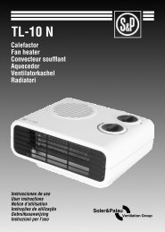
RECUPERADORES DE CALORHEAT RECOVERY UNITSRECUPERATEURS DE CHALEURCADB-D/DI/DCCADT-D/DI/DCMANUAL DE INSTALACIÓN, USO Y MANTENIMIENTOINSTALLATION, USE AND MAINTENANCE MANUALNOTICE D’INSTALLATION, D’UTILISATION ET DE MAINTENANCE
ESPAÑOLÍNDICE1. Generalida<strong>de</strong>s 42. Normas <strong>de</strong> seguridad y marcado “CE” 43. Normas generales 44. Etiquetado <strong>de</strong> la unidad 45. Manipulación 46. Simbología instrucciones 47. Instalación 57.1. Generalida<strong>de</strong>s 57.2. Espacio para mantenimiento 57.3. Conexiones 57.3.1. Conexión canalizaciones 57.3.1.1. Conexión canalización <strong>de</strong> aire 57.3.1.2. Conexión canalización baterias <strong>de</strong> agua 67.3.2. Conexión a la red eléctrica 67.3.2.1. Conexión <strong>de</strong> motores 67.3.2.2. Conexión resistencias <strong>de</strong> apoyo CADB-DI 77.3.3. Evacuación <strong>de</strong> con<strong>de</strong>nsados 87.4. Configuraciones horizontales 87.4.1. Mo<strong>de</strong>los CADB/CADT-D 05 / 08 / 18 / 30 / 45 / 56 AH DP 87.4.2. Mo<strong>de</strong>los CADB/CADT-D 05 / 08 / 18 / 30 / 45 / 56 AH DP BP 87.4.3. Mo<strong>de</strong>los CADB/CADT-DI 05 / 08 / 18 / 30 / 45 / 56 (A-D-E-G)H DP 97.4.4. Mo<strong>de</strong>los CADB/CADT-DI 05 / 08 / 18 / 30 / 45 / 56 (A-D-E-G)H DP BP 97.4.5. Mo<strong>de</strong>los CADB/CADT-DC 05 / 08 / 18 / 30 / 45 / 56 (A-D-E-G)H DP 107.4.6. Mo<strong>de</strong>los CADB/CADT-DC 05 / 08 / 18 / 30 / 45 / 56(A-E-D-G)H DP BP 107.5. Configuraciones verticales 117.5.1. Mo<strong>de</strong>los CADB/CADT-D 05 / 08 / 18 / 30 / 45 / 56 AV DP 117.5.2. Mo<strong>de</strong>los CADB/CADT-D 05 / 08 / 18 / 30 / 45 / 56 AV DP BP 117.5.3. Mo<strong>de</strong>los CADB/CADT-DI 05 / 08 / 18 / 30 / 45 / 56 (A-C-E)V DP 117.5.4. Mo<strong>de</strong>los CADB/CADT-DI 05 / 08 / 18 / 30 / 45 / 56 (A-C-E)V DP BP 117.5.5. Mo<strong>de</strong>los CADB/CADT-DC 05 / 08 / 18 / 30 / 45 / 56 (A-C-E)V DP 127.5.6. Mo<strong>de</strong>los CADB/CADT-DC 05 / 08 / 18 / 30 / 45 / 56 (A-C-E)V DP BP 128. Conexión <strong>de</strong>l motor <strong>de</strong>l by - pass 139. Puesta en marcha 1310. Inspección, mantenimiento y limpieza 1310.1. Filtros 1310.2. Intercambiador <strong>de</strong> <strong>calor</strong> 1410.3. Tubo <strong>de</strong> <strong>de</strong>sagüe <strong>de</strong> con<strong>de</strong>nsados 1411. Anomalías <strong>de</strong> funcionamiento 143
1. GENERALIDADESLe agra<strong>de</strong>cemos la confianza que ha <strong>de</strong>positado en nosotros mediante la compra <strong>de</strong> este aparato. Usted ha adquirido un producto <strong>de</strong> calidadque ha sido totalmente fabricado según las reglas técnicas <strong>de</strong> seguridad reconocidas y conformes a las normas <strong>de</strong> la CE.Lea atentamente el contenido <strong>de</strong>l presente libro <strong>de</strong> instrucciones, pues contiene indicaciones importantes para su seguridad durante lainstalación, el uso y el mantenimiento <strong>de</strong> este producto.Consérvelo para una posible consulta posterior.Rogamos compruebe el perfecto estado <strong>de</strong>l aparato al <strong>de</strong>sembalarlo, ya que cualquier <strong>de</strong>fecto <strong>de</strong> origen que presente, está amparado porla garantía S&P.2. NORMAS DE SEGURIDAD Y MARCADO “CE”Los técnicos <strong>de</strong> S&P están firmemente comprometidos en la investigación y <strong>de</strong>sarrollo <strong>de</strong> productos cada vez más eficientes y que cumplancon las normas <strong>de</strong> seguridad en vigor.Las normas y recomendaciones que se indican a continuación, reflejan las normas vigentes, preferentemente en materia <strong>de</strong> seguridad y por lotanto se basan principalmente en el cumplimiento <strong>de</strong> las normas <strong>de</strong> carácter general. Por consiguiente, recomendamos a todas las personasexpuestas a riesgos que se atengan escrupulosamente a las normas <strong>de</strong> prevención <strong>de</strong> acci<strong>de</strong>ntes en vigor en su país.S&P queda eximido <strong>de</strong> cualquier responsabilidad por eventuales daños causados a personas y cosas <strong>de</strong>rivados <strong>de</strong> la falta <strong>de</strong> cumplimiento<strong>de</strong> las normas <strong>de</strong> seguridad, así como <strong>de</strong> posibles modificaciones en el producto.El sello CE y la correspondiente <strong>de</strong>claración <strong>de</strong> conformidad, atestiguan la conformidad con las normas comunitarias aplicables.3. NORMAS GENERALESSe ha realizado el análisis <strong>de</strong> los riesgos <strong>de</strong>l producto como está previsto en la Directiva <strong>de</strong> Máquinas.Este manual contiene la información <strong>de</strong>stinada a todo el personal expuesto, con el fin <strong>de</strong> prevenir posibles daños a personas y/o cosas, acausa <strong>de</strong> una <strong>de</strong>fectuosa manipulación o mantenimiento.Todas las intervenciones <strong>de</strong> mantenimiento (ordinario y extraordinario) <strong>de</strong>ben ser realizadas con la máquina parada y la alimentación eléctrica<strong>de</strong>sconectada.Para evitar el peligro <strong>de</strong> posible arranque acci<strong>de</strong>ntal, ponga en el cuadro eléctrico central y en la consola <strong>de</strong> control, carteles <strong>de</strong> advertenciacon el siguiente contenido:“Atención: control <strong>de</strong>sconectado para operaciones <strong>de</strong> mantenimiento”Antes <strong>de</strong> conectar el cable <strong>de</strong> alimentación eléctrica a la regleta, verifique que la tensión <strong>de</strong> la línea correspon<strong>de</strong> a la indicada en la placa <strong>de</strong>características <strong>de</strong> la unidad.Verifique periódicamente las etiquetas <strong>de</strong>l producto. Si con el paso <strong>de</strong>l tiempo son ilegibles, <strong>de</strong>ben ser sustituidas.4. ETIQUETADO DE LA UNIDADLa máquina pue<strong>de</strong> estar provista <strong>de</strong> diversos pictogramas <strong>de</strong> señalización, que no <strong>de</strong>ben ser eliminados. Las señales se divi<strong>de</strong>n en:- Señales <strong>de</strong> prohibición: No reparar o ajustar durante el funcionamiento.- Señales <strong>de</strong> peligro: Señala la presencia <strong>de</strong> elementos con tensión en el interior <strong>de</strong>l contenedor sobre el que aparece el cartel.- Señales <strong>de</strong> i<strong>de</strong>ntificación: Tarjeta CE, indica los datos <strong>de</strong>l producto y dirección <strong>de</strong>l fabricante. La marca CE, indica la conformidad <strong>de</strong>lproducto, según las normas CEE.Señal <strong>de</strong> peligroSeñal <strong>de</strong> prohibición5. MANIPULACIÓNAntes <strong>de</strong> proce<strong>de</strong>r a la instalación, asegúrese <strong>de</strong> que el medio utilizado para <strong>de</strong>splazar y/o izar el aparato, tenga la capacidad suficiente.6. SIMBOLOGÍA INSTRUCCIONESBATERÍADE AGUAVENTILADORCENTRÍFUGOFILTROAIRE EXTRAÍDOBATERÍAELÉCTRICAAISLAMIENTODOBLE PAREDDESAGÜEAIRE NUEVO4
7.3.3. EVACUACIÓN DE CONDENSADOSEl instalador siempre <strong>de</strong>be conectar el tubo <strong>de</strong> <strong>de</strong>scarga <strong>de</strong> con<strong>de</strong>nsados, en el lado <strong>de</strong> expulsión <strong>de</strong>l aire interior “contaminado”, hacia elexterior. Dicha conexión <strong>de</strong>be realizarse mediante un tubo <strong>de</strong> 10 mm <strong>de</strong> diámetro interior y una brida para asegurar su fijación.Para evitar el retorno <strong>de</strong> los con<strong>de</strong>nsados por <strong>de</strong>presión al interior <strong>de</strong>l aparato, se aconseja realizar un sifón con el tubo <strong>de</strong> <strong>de</strong>scarga <strong>de</strong> con<strong>de</strong>nsados.Teniendo en cuenta que esta configuración, tiene dos posibles conexiones para el tubo <strong>de</strong> evacuación <strong>de</strong> con<strong>de</strong>nsados, seguidamente lesindicamos algunos ejemplos con aparatos <strong>de</strong> configuración horizontal.Véase que la ubicación correcta <strong>de</strong>l tubo <strong>de</strong> evacuación <strong>de</strong> con<strong>de</strong>nsados, correspon<strong>de</strong> al lado <strong>de</strong> expulsión <strong>de</strong>l aire interior “contaminado”,hacia el exterior (línea roja).Ejemplo 1Configuración horizontalLado Correcto correctoLadoIncorreincorrectoEjemplo 2Configuración verticalLado correctoLado incorrecto7.4. CONFIGURACIONES HORIZONTALES7.4.1. MODELOS CADB/CADT-D 05 / 08 / 18 / 30 / 45/ 56 AH DPMo<strong>de</strong>los sin batería eléctrica, pero con la posibilidad <strong>de</strong> instalar batería<strong>de</strong> agua, <strong>de</strong> post-calentamiento en configuración <strong>de</strong> instalaciónremota, con doble pared <strong>de</strong> aislamiento y sin by-pass.Los flujos <strong>de</strong> aire indicados en estas configuraciones, pue<strong>de</strong>n serintercambiados en función <strong>de</strong> la instalación.El instalador solo <strong>de</strong>berá tener en cuenta la correcta conexión <strong>de</strong>l sistema <strong>de</strong>evacuación <strong>de</strong>l agua generada por con<strong>de</strong>nsación (véase apartado 7.3.3).7.4.2. MODELOS CADB/CADT-D 05 / 08 / 18 / 30 / 45 /56 AH DP BPMo<strong>de</strong>los sin batería eléctrica, pero con la posibilidad <strong>de</strong> instalar batería<strong>de</strong> agua <strong>de</strong> post-calentamiento, en configuración <strong>de</strong> instalaciónremota, doble pared <strong>de</strong> aislamiento y con by-pass.Los flujos <strong>de</strong> aire indicados en estas configuraciones NO pue<strong>de</strong>n serintercambiados en función <strong>de</strong> la instalación.El instalador <strong>de</strong>berá tener en cuenta la correcta conexión <strong>de</strong>l sistema <strong>de</strong>evacuación <strong>de</strong>l agua generada por con<strong>de</strong>nsación (véase apartado 7.3.3).8
7.4.3. MODELOS CADB/CADT-DI 05 / 08 / 18 / 30 / 45 / 56 (A-D-E-G)H DP(Monofásico y trifásico)Mo<strong>de</strong>los con doble pared <strong>de</strong> aislamiento, batería eléctrica <strong>de</strong> post-calentamiento y sin by-pass.Los flujos <strong>de</strong> aire indicados en estas configuraciones, NO pue<strong>de</strong>n ser intercambiados en función <strong>de</strong> la instalación.El instalador <strong>de</strong>berá tener en cuenta la correcta conexión <strong>de</strong>l sistema <strong>de</strong> evacuación <strong>de</strong>l agua generada por con<strong>de</strong>nsación (véase apartado 7.3.3).No están autorizados posicionamientos <strong>de</strong> las resistencias <strong>de</strong> post-calentamiento, <strong>de</strong> forma diferente a los suministrados <strong>de</strong> fábrica.MODELOS CADB/CADT-DI 05 / 08 / 18 / 30 / 45 / 56 AH DPMODELOS CADB/CADT-DI 05 / 08 / 18 / 30 / 45 / 56 DH DPMODELOS CADB/CADT-DI 05 / 08 / 18 / 30 / 45 / 56 EH DPMODELOS CADB/CADT-DI 05 / 08 / 18 / 30 45 / 56 GH DP7.4.4. MODELOS CADB/CADT-DI 05 / 08 / 18 / 30 / 45 / 56 (A-D-E-G)H DP BP(Monofásico y trifásico)Mo<strong>de</strong>los con doble pared <strong>de</strong> aislamiento, batería eléctrica <strong>de</strong> post-calentamiento y con by-pass.Los flujos <strong>de</strong> aire indicados en estas configuraciones, NO pue<strong>de</strong>n ser intercambiados en función <strong>de</strong> la instalación.El instalador <strong>de</strong>berá tener en cuenta la correcta conexión <strong>de</strong>l sistema <strong>de</strong> evacuación <strong>de</strong>l agua generada por con<strong>de</strong>nsación (véase apartado 7.3.3).No están autorizados posicionamientos <strong>de</strong> las resistencias <strong>de</strong> post-calentamiento, <strong>de</strong> forma diferente a los suministrados <strong>de</strong> fábrica.MODELOS CADB/CADT-DI 05 / 08 / 18 / 30 / 45 / 56 AH DPMODELOS CADB/CADT-DI 05 / 08 / 18 / 30 / 45 / 56 DH DPMODELOS CADB/CADT-DI 05 / 08 / 18 / 30 / 45 / 56 EH DPMODELOS CADB/CADT-DI 05 / 08 / 18 / 30 / 45 / 56 GH DP9
7.4.5. MODELOS CADB/CADT-DC 05 / 08 / 18 / 30 / 45 / 56 (A-D-E-G)H DP(Monofásico y trifásico)Mo<strong>de</strong>los con doble pared <strong>de</strong> aislamiento, batería <strong>de</strong> agua <strong>de</strong> post-calentamiento y sin by-pass.Los flujos <strong>de</strong> aire indicados en estas configuraciones, NO pue<strong>de</strong>n ser intercambiados en función <strong>de</strong> la instalación.El instalador <strong>de</strong>berá tener en cuenta la correcta conexión <strong>de</strong>l sistema <strong>de</strong> evacuación <strong>de</strong>l agua generada por con<strong>de</strong>nsación (véase apartado 7.3.3).No están autorizados posicionamientos <strong>de</strong> las baterías <strong>de</strong> agua <strong>de</strong> post-calentamiento, <strong>de</strong> forma diferente a los suministrados <strong>de</strong> fábrica.MODELOS CADB/CADT-DC 05 / 08 / 18 / 30 / 45 / 56 AH DPMODELOS CADB/CADT-DC 05 / 08 / 18 / 30 / 45 / 56 DH DPMODELOS CADB/CADT-DC 05 / 08 / 18 / 30 / 45 / 56 EH DPMODELOS CADB/CADT-DC 05 / 08 / 18 / 30 45 / 56 GH DP7.4.6. MODELOS CADB/CADT-DC 05 / 08 / 18 / 30 / 45 / 56(A-E-D-G)H DP BP(Monofásico y trifásico)Mo<strong>de</strong>los con doble pared <strong>de</strong> aislamiento, batería <strong>de</strong> agua <strong>de</strong> post-calentamiento y con by-pass.Los flujos <strong>de</strong> aire indicados en estas configuraciones, NO pue<strong>de</strong>n ser intercambiados en función <strong>de</strong> la instalación.El instalador <strong>de</strong>berá tener en cuenta la correcta conexión <strong>de</strong>l sistema <strong>de</strong> evacuación <strong>de</strong>l agua generada por con<strong>de</strong>nsación (véase apartado 7.3.3).No están autorizados posicionamientos <strong>de</strong> las baterías <strong>de</strong> agua <strong>de</strong> post-calentamiento, <strong>de</strong> forma diferente a los suministrados <strong>de</strong> fábrica.MODELOS CADB/CADT-DC 05 / 08 / 18 / 30 / 45 / 56 AH DP BP MODELOS CADB/CADT-DC 05 / 08 / 18 / 30 / 45 / 56 DH DP BPMODELOS CADB/CADT-DC 05 / 08 / 18 / 30 / 45 / 56 EH DP BPMODELOS CADB/CADT-DC 05 / 08 / 18 / 30 45 / 56 GH DP BP10
7.5. CONFIGURACIONES VERTICALES7.5.1. MODELOS CADB/CADT-D 05 / 08 / 18 / 30 / 45/ 56 AV DPMo<strong>de</strong>los sin batería eléctrica, pero con la posibilidad <strong>de</strong> instalar batería<strong>de</strong> agua, <strong>de</strong> post-calentamiento en configuración <strong>de</strong> instalación remota,con doble pared <strong>de</strong> aislamiento y sin by-pass.Los flujos <strong>de</strong> aire indicados en estas configuraciones, pue<strong>de</strong>n ser intercambiadosen función <strong>de</strong> la instalación.El instalador solo <strong>de</strong>berá tener en cuenta la correcta conexión <strong>de</strong>l sistema <strong>de</strong>evacuación <strong>de</strong>l agua generada por con<strong>de</strong>nsación (véase apartado 7.3.3).A partir <strong>de</strong> la configuración <strong>de</strong> fábrica, po<strong>de</strong>mos configurar el aparato,teniendo en cuenta que po<strong>de</strong>mos girar el mismo modificando la posición<strong>de</strong> los pies <strong>de</strong> soporte, y a su vez, también tendremos que modificar laposición <strong>de</strong> la ban<strong>de</strong>ja “recoge agua” según la configuración elegida.7.5.2. MODELOS CADB/CADT-D 05 / 08 / 18 / 30 / 45 /56 AV DP BPMo<strong>de</strong>los sin batería eléctrica, pero con la posibilidad <strong>de</strong> instalar batería<strong>de</strong> agua <strong>de</strong> post-calentamiento en configuración <strong>de</strong> instalaciónremota, doble pared <strong>de</strong> aislamiento y con by-pass.Los flujos <strong>de</strong> aire indicados en estas configuraciones, NO pue<strong>de</strong>n serintercambiados en función <strong>de</strong> la instalación.7.5.3. MODELOS CADB/CADT-DI 05 / 08 / 18 / 30 / 45 / 56 (A-C-E)V DP(Monofásico y trifásico)Mo<strong>de</strong>los con doble pared <strong>de</strong> aislamiento, batería <strong>de</strong> agua <strong>de</strong> post-calentamiento y sin by-pass.Los flujos <strong>de</strong> aire indicados en estas configuraciones, NO pue<strong>de</strong>n ser intercambiados en función <strong>de</strong> la instalación.El instalador <strong>de</strong>berá tener en cuenta la correcta conexión <strong>de</strong>l sistema <strong>de</strong> evacuación <strong>de</strong>l agua generada por con<strong>de</strong>nsación (véase apartado 7.3.3).No están autorizados posicionamientos <strong>de</strong> las baterías <strong>de</strong> agua <strong>de</strong> post-calentamiento, <strong>de</strong> forma diferente a los suministrados <strong>de</strong> fábrica.MODELOS CADB/CADT-DI 05 / 08 / 18 / 30 / 45 / 56 AV DPMODELOS CADB/CADT-DI 05 / 08 / 18 / 30 / 45 / 56 CV DPMODELOS CADB/CADT-DI 05 / 08 / 18 / 30 / 45 / 56 EV DP7.5.4. MODELOS CADB/CADT-DI 05 / 08 / 18 / 30 / 45 / 56 (A-C-E)V DP BP(Monofásico y trifásico)Mo<strong>de</strong>los con doble pared <strong>de</strong> aislamiento, batería <strong>de</strong> agua <strong>de</strong> post-calentamiento y con by-pass.Los flujos <strong>de</strong> aire indicados en estas configuraciones, NO pue<strong>de</strong>n ser intercambiados en función <strong>de</strong> la instalación.El instalador <strong>de</strong>berá tener en cuenta la correcta conexión <strong>de</strong>l sistema <strong>de</strong> evacuación <strong>de</strong>l agua generada por con<strong>de</strong>nsación (véase apartado 7.3.3).No están autorizados posicionamientos <strong>de</strong> las baterías <strong>de</strong> agua <strong>de</strong> post-calentamiento, <strong>de</strong> forma diferente a los suministrados <strong>de</strong> fábrica.11
MODELOS CADB/CADT-DI 05 / 08 / 18 / 30 / 45 / 56 AV DP BPMODELOS CADB/CADT-DI 05 / 08 / 18 / 30 / 45 / 56 CV DP BPMODELOS CADB/CADT-DI 05 / 08 / 18 / 30 / 45 / 56 EV DP BP7.5.5. MODELOS CADB/CADT-DC 05 / 08 / 18 / 30 / 45 / 56 (A-C-E)V DP(Monofásico y trifásico)Mo<strong>de</strong>los con doble pared <strong>de</strong> aislamiento, batería <strong>de</strong> agua <strong>de</strong> post-calentamiento y sin by-pass.Los flujos <strong>de</strong> aire indicados en estas configuraciones, NO pue<strong>de</strong>n ser intercambiados en función <strong>de</strong> la instalación.El instalador <strong>de</strong>berá tener en cuenta la correcta conexión <strong>de</strong>l sistema <strong>de</strong> evacuación <strong>de</strong>l agua generada por con<strong>de</strong>nsación (véase apartado 7.3.3).No están autorizados posicionamientos <strong>de</strong> las baterías <strong>de</strong> agua <strong>de</strong> post-calentamiento, <strong>de</strong> forma diferente a los suministrados <strong>de</strong> fábrica.MODELOS CADB/CADT-DC 05 / 08 / 18 / 30 / 45 / 56 AV DPMODELOS CADB/CADT-DC 05 / 08 / 18 / 30 / 45 / 56 CV DPMODELOS CADB/CADT-DC 05 / 08 / 18 / 30 / 45 / 56 EV DP7.5.6. MODELOS CADB/CADT-DC 05 / 08 / 18 / 30 / 45 / 56 (A-C-E)V DP BP(Monofásico y trifásico)Mo<strong>de</strong>los con doble pared <strong>de</strong> aislamiento, batería <strong>de</strong> agua <strong>de</strong> post-calentamiento y con by-pass.Los flujos <strong>de</strong> aire indicados en estas configuraciones, NO pue<strong>de</strong>n ser intercambiados en función <strong>de</strong> la instalación.El instalador <strong>de</strong>berá tener en cuenta la correcta conexión <strong>de</strong>l sistema <strong>de</strong> evacuación <strong>de</strong>l agua generada por con<strong>de</strong>nsación (véase apartado 7.3.3).No están autorizados posicionamientos <strong>de</strong> las baterías <strong>de</strong> agua <strong>de</strong> post-calentamiento, <strong>de</strong> forma diferente a los suministrados <strong>de</strong> fábrica.12
MODELOS CADB/CADT-DC 05 / 08 / 18 / 30 / 45 / 56 AV DP BPMODELOS CADB/CADT-DC 05 / 08 / 18 / 30 / 45 / 56 CV DP BPMODELOS CADB/CADT-DC 05 / 08 / 18 / 30 / 45 / 56 EV DP BP8. CONEXIÓN DEL MOTOR DEL BY – PASSPara la instalación véase lo anteriormente <strong>de</strong>scrito, <strong>de</strong>pendiendo <strong>de</strong>ltipo <strong>de</strong> instalación (configuración horizontal o vertical) y conecte elservomotor <strong>de</strong>l by-pass (montado en fábrica) tal y como se indicaen la siguiente figura:9. PUESTA EN MARCHAREDAC 230 VAntes <strong>de</strong> la puesta en marcha, es conveniente realizar las siguientes verificaciones:- Asegúrese <strong>de</strong> que en el interior <strong>de</strong>l aparato no haya cuerpos extraños y que todos los componentes estén fijos en su lugar.- Compruebe manualmente que el ventilador no roza en las pare<strong>de</strong>s.- Verifique que la trampilla <strong>de</strong> inspección este cerrada.ATENCIÓN:Si las bocas <strong>de</strong> un ventilador no están canalizadas se <strong>de</strong>be instalar una red <strong>de</strong> protección a<strong>de</strong>cuada.Verifique la conexión eléctrica <strong>de</strong> toma <strong>de</strong> tierra.La conexión eléctrica <strong>de</strong>be ser realizada por personal cualificado.AZUL (4)NEGRO (6)BLANCO (7)10. INSPECCIÓN, MANTENIMIENTO Y LIMPIEZA10.1. FILTROSEl control <strong>de</strong>l estado <strong>de</strong> obstrucción <strong>de</strong> los filtros, pue<strong>de</strong> efectuarse a través <strong>de</strong> las tomas <strong>de</strong> presión especiales situadas a ambos lados <strong>de</strong> losfiltros, en el costado inferior <strong>de</strong> la unidad, en el caso <strong>de</strong> la configuración horizontal, y en uno <strong>de</strong> los lados, en caso <strong>de</strong> configuración vertical,conectándolo a un presostato diferencial.La caída <strong>de</strong> presión máxima recomendada en los filtros estándar G4 es <strong>de</strong> 130/150 Pa.- Inspección por el lado <strong>de</strong> la unidad:Utilizando un <strong>de</strong>stornillador <strong>de</strong> corte, hacer rotar el cierre <strong>de</strong>l “Panel <strong>de</strong> inspección <strong>de</strong> filtro” hacia la izquierda y quitar el panel.Hacer presión en el filtro hacia la <strong>de</strong>recha en los clips <strong>de</strong> sujeción y extraer el filtro.- Inspección <strong>de</strong>l bajo:Soltar los pestillos <strong>de</strong> cierre <strong>de</strong>l “Panel <strong>de</strong> inspección <strong>de</strong> filtros” y sacar el panel, agarrar la manilla <strong>de</strong>l filtro y <strong>de</strong>sbloquear los clips que losostienen, estirando a continuación hacia abajo.- Mantenimiento periódico aconsejado:En función <strong>de</strong> la contaminación <strong>de</strong>l aire ambiente (polvo, humo…), se recomienda sustituir el filtro entre 15 y 30 días como máximo.13
10.2. INTERCAMBIADOR DE CALORUtilizando un <strong>de</strong>stornillador <strong>de</strong> corte, extraer los cuatro tornillos <strong>de</strong> los pestillos <strong>de</strong>l panel <strong>de</strong> inspección <strong>de</strong>l intercambiador.Rotar los cuatro pestillos <strong>de</strong> anclaje hasta liberar la tapa <strong>de</strong>l panel para su posterior extracción.Utilizando un <strong>de</strong>stornillador <strong>de</strong> estrella, soltar los tornillos <strong>de</strong> fijación <strong>de</strong> la barra <strong>de</strong> seguridad situada en el ángulo <strong>de</strong>l intercambiador.Girar la barra <strong>de</strong> seguridad hasta liberar el intercambiador.10.3. TUBO DE DESAGÜE DE CONDENSADOS11. ANOMALÍAS DE FUNCIONAMIENTOANOMALÍA CAUSA SOLUCIÓNArranque difícil.Caudal <strong>de</strong> aire insuficiente.Presión insuficiente.Caída <strong>de</strong> rendimiento<strong>de</strong>spués <strong>de</strong> un periodo <strong>de</strong>funcionamiento aceptable.Temperatura aire nuevo<strong>de</strong>masiado fría.Rendimiento insuficiente <strong>de</strong>lintercambiador.Formación <strong>de</strong> escarcha enel intercambiador.Pulsación <strong>de</strong> aire.¡¡¡ATENCIÓN!!! Sostener con una mano el intercambiador durante esta operación para evitar su caídapor gravedad (riesgo <strong>de</strong> daños en el intercambiador y riesgo <strong>de</strong> acci<strong>de</strong>nte para el técnico que realiza laoperación).Para extraer el intercambiador <strong>de</strong> su ubicación, <strong>de</strong>slícelo por sus guías, tirando <strong>de</strong> los ángulos y no <strong>de</strong> lasaletas <strong>de</strong>l intercambiador, para no dañarlo.Limpie el intercambiador con aire comprimido o con un aspirador y lávelo con <strong>de</strong>tergente no agresivo.El mantenimiento periódico recomendado es <strong>de</strong> una vez por cada estación en funcionamiento.Inspeccione periódicamente el tubo <strong>de</strong> <strong>de</strong>sagüe <strong>de</strong> con<strong>de</strong>nsados, para evitar que que<strong>de</strong> atascado y, en ese caso, retire los restos que loatasquen.Tensión <strong>de</strong> alimentación reducida.Par estático <strong>de</strong>l motor insuficiente.Tuberías atascadas y/o puntos <strong>de</strong>aspiración cerrados.Ventilador obstruido.Filtro sobrecargado.Velocidad <strong>de</strong> rotación insuficiente.Paquete intercambiador obturado.Fuga en el circuito antes y/o <strong>de</strong>spués<strong>de</strong>l ventilador.Ro<strong>de</strong>te dañado.Aire exterior inferior a -5º C.Mo<strong>de</strong>los (CADB-DI): Protectores térmicos.Resistencias <strong>de</strong> Apoyo abiertos.Aletas intercambio sucias.Aire exterior inferior a -5º C.Ventilador que trabaja en condiciones<strong>de</strong> caudal casi igual a 0.Inestabilidad <strong>de</strong> flujo, obstrucción omala conexión.Verificar datos <strong>de</strong> placa <strong>de</strong>l motor.Cerrar las entradas <strong>de</strong> aire para alcanzar la máxima velocidad.Si es necesario, cambie el motor.Contacte con el Servicio Post Venda <strong>de</strong> S&P.Limpieza <strong>de</strong> los tubos <strong>de</strong> aspiración.Limpieza <strong>de</strong>l ventilador.Limpiar o sustituir el filtro.Verificar la tensión <strong>de</strong> alimentación.Limpieza <strong>de</strong>l intercambiador.Verificación <strong>de</strong>l circuito y restauración <strong>de</strong> las condiciones originales.Verificar el ro<strong>de</strong>te y en caso necesario, sustituirlo con un recambiooriginal. Contacte con el Servicio Post Venda <strong>de</strong> S&P.Inserción dispositivos <strong>de</strong> postcalentamiento.Contacte con el Servicio Post Venda <strong>de</strong> S&P.Rearme mediante el pulsador RESET, todos los protectores térmicos <strong>de</strong>la resistencia.Limpieza <strong>de</strong>l intercambiador.Inserción <strong>de</strong> dispositivos <strong>de</strong> precalentamiento (anti-hielo).Contacte con el Servicio <strong>de</strong> Asesorías <strong>de</strong> S&P.Modificación <strong>de</strong>l circuito y/o sustitución <strong>de</strong>l ventilador.Limpieza y/o reajuste canales <strong>de</strong> aspiración. Intervenir en el reguladorelectrónico aumentando la velocidad mínima (voltaje insuficiente).Contacte con el Servicio <strong>de</strong> Asesorías <strong>de</strong> S&P.14
7. INSTALLATION7.1. INTRODUCTIONHorizontally configured mo<strong>de</strong>ls are <strong>de</strong>signed to be installed hanging from the ceiling or located insi<strong>de</strong> a false ceiling.The appliance has four metal abutments, one on each lower corner. Using stud<strong>de</strong>d rods (Ø 6 mm or Ø 8 mm), it can be secured to the ceilingand levelled.The installer must make sure that the ceiling structure and thesecuring elements can bear the weight of the <strong>de</strong>vice, taking intoaccount that it is a dynamic load.Vertical configuration mo<strong>de</strong>ls have special support feet.Once the <strong>de</strong>vice has been fitted in the correct position, the installermust connect it with the air duct, the mains connection, both for themotors, and for the batteries, if applicable, by means of the terminalsin the terminal connection box and the connection with the hot waterclosed circuit for the water battery, if applicable. The tube for evacuatingcon<strong>de</strong>nsates will be secured according to the instructions in thecorresponding section.7.2. MAINTENANCE SPACEHorizontalMo<strong>de</strong>lA(mm)B(mm)C(mm)D(mm)CADB-D/DI/DC 05 345 400 400 640ACADB-D/DI/DC 08 360 400 400 820CADB-D/DI/DC 18 535 400 600 1040CCADB-D/DI/DC 30 630 500 700 1270BDBDBCADT-D/DI/DC 45 855 500 900 1300CADT-D/DI/DC 56 855 500 900 1300VerticalBAMo<strong>de</strong>lA(mm)B(mm)C(mm)CADB-D/DI/DC 05 400 640 740CADB-D/DI/DC 08 400 820 920CADB-D/DI/DC 18 600 1040 1140CCADB-D/DI/DC 30 700 1270 1370CADT-D/DI/DC 45 900 1300 1300100CADT-D/DI/DC 56 900 1300 13007.3. CONNECTIONS7.3.1. PIPING AND DUCT CONNECTIONS7.3.1.1. CONNECTION WITH AIR DUCTThe standard configuration displays the route of fresh air blown into the premises in blue, while used air and its route until it is expelled from thepremised is in red.The fans are always blowing out with regard to the machine.The fans must not be positioned in a manner different to the one indicated.17
7.3.1.2. CONNECTING THE WATER BATTERY PIPINGIf post-<strong>heat</strong>ing water batteries are used, take into account the typeof <strong>de</strong>vice installed, thus:For mo<strong>de</strong>ls CADB-D, the installation of water batteries is remote, asthe water battery is outsi<strong>de</strong> the <strong>de</strong>vice, placed in any part of the ductthe user wishes, on the si<strong>de</strong> of blowing the air insi<strong>de</strong>, as can be seenin the following illustration.The user or installer must only install the water coil in the most convenientpoint, then connect the water coil inlet and outlet pipes (Halfan inch for mo<strong>de</strong>ls 05, 08 and 18, and one inch for mo<strong>de</strong>ls 30, 45 and56), to the hot water circuit.For CADB-DI mo<strong>de</strong>ls, the reference is changed to CADB-DC and theinstallation of the water batteries is called direct, as the water coil isbuilt into the appliance.The user or installer only needs to collect the water coil inlet andoutlet tubes to its hot water closed circuit.WATER COILWATER COILREMOTE INSTALLATIONDIRECT INSTALLATION7.3.2. CONNECTING TO THE MAINS7.3.2.1. CONNECTING THE MOTORSFor two-phase, four-speed mo<strong>de</strong>ls 05 and 08, the electrical connectionwill be ma<strong>de</strong> as <strong>de</strong>scribed in the following illustration:For two-phase, three-speed mo<strong>de</strong>ls 18 and 30, electrical connectionwill be ma<strong>de</strong> as <strong>de</strong>scribed in the following illustration:YELLOW / GREENYELLOW / GREENMBLUEWHITEREDGREYBLACKN1ª SPEED2ª SPEED3ª SPEED4ª MAX. SPEEDMBLUEBLACK / REDBROWNBLACKN1ª SPEED2ª SPEED3ª MAX SPEEDFor two-phase, one-speed mo<strong>de</strong>ls 45 and 56, electrical connection will be ma<strong>de</strong> as <strong>de</strong>scribed in the following illustration:YELLOW / GREENBROWN / GREYBLACK / BLUEWHITE / REDORANGEORANGEPERSTTM400VIn the first two cases, if you wish to have the appliance connected at a fixed speed, just choose which you need and connect the earth, theneutral and the <strong>de</strong>sired speed, always taking into account that both fans must work at the same speed.If you wish to have greater control, and to be able to control the speed of operation of the <strong>de</strong>vice, please contact your official S&P <strong>de</strong>aler, whowill inform you of the wi<strong>de</strong> range of S&P accessories that are available.18
7.3.2.2. CONNECTING SUPPORT RESISTANCES CADB-DIIf the mo<strong>de</strong>l is regulated by a control: BASIC, PROGRAM, ADVANZ or DOMO, see the attached instructions for making electrical connections.For SINGLE-PHASE mo<strong>de</strong>ls 05/08/18/30, electrical connection will be ma<strong>de</strong> as <strong>de</strong>scribed in the following illustration:CADB-DI 05230V 2KWCADB-DI 08230V 4KWMANUALRESET2KW230VMANUALRESET2KW230VMANUALRESET2KW230VA1 1 3 5A2 2 4 6230V AC12A (min)cos 1A1 1 3A2 2 4230V AC12A (min)cos 1A1 1 3A2 2 4230V AC12A (min)cos 1L230V AC N50HzL230V AC N50HzCADB-DI 18230V 6KWCADB-DI 30 MONO230V 8KWMANUALRESET3KW230VMANUALRESET3KW230VMANUALRESET4KW230VMANUALRESET4KW230VA1 1 3A2 2 4230V AC20A (min)cos 1A1 1 3A2 2 4230V AC20A (min)cos 1A1 1 3A2 2 4230V AC25A (min)cos 1A1 1 3A2 2 4230V AC25A (min)cos 1230V AC50HzLN230V AC50HzLNFor THREE-PHASE mo<strong>de</strong>ls 30/45/56, electrical connection will be ma<strong>de</strong> as <strong>de</strong>scribed in the following illustration:CADB-DI 30 TRI400V 8KWCADB-DI 45 TRI400V 12KWMANUALRESET4KW400VMANUALRESET4KW400VMANUALRESET6KW400VMANUALRESET6KW400VA1 1 3A2 2 456230V AC25A (min)cos 1A1 1 3A2 2 456230V AC25A (min)cos 1A1 1 3A2 2 456230V AC25A (min)cos 1A1 1 3A2 2 456230V AC25A (min)cos 1400VAC50HzRSTN400V AC50HzRSTNCADB-DI 56 TRI400V 12KWMANUALRESET6KW400VMANUALRESET6KW400VA1 1 35230V AC25A (min)A1 1 35230V AC25A (min)A2 2 46cos 1A2 2 46cos 1400V AC50HzRSTN19
7.3.3. EVACUATION OF CONDENSATEThe installer must always connect the con<strong>de</strong>nsate evacuation tube on the outlets si<strong>de</strong> of the interior “used” air, to the outsi<strong>de</strong>. This connectionmust be ma<strong>de</strong> with a 10 mm internal diameter tube and a tie to secure it.To avoid the con<strong>de</strong>nsates returning to the appliance, we recommend fitting a siphon to the con<strong>de</strong>nsate evacuation tube.Bearing in mind that this configuration has two possible connections for the con<strong>de</strong>nsate evacuation tube, we will show some examples withhorizontally configured appliances.Observe that the correct location of the con<strong>de</strong>nsate evacuation tube is on the si<strong>de</strong> where the “used” interior air is expelled (red line).Example 1Horizontal configurationCorrect Lado Correcto si<strong>de</strong>Incorrect Lado si<strong>de</strong>Example 2Vertical configurationCorrect Lado correcto si<strong>de</strong>Incorrect Lado incorrecto si<strong>de</strong>7.4. HORIZONTAL CONFIGURATIONS7.4.1. CADB/CADT-D 05 / 08 / 18 / 30 / 45 / 56 AH DPMODELSMo<strong>de</strong>ls without an electric battery, but with the possibility of installinga water coil, for post-<strong>heat</strong>ing in remote installation configuration,with a double insulation wall and no by-pass.The airflows indicted in these configurations can be changed, accordingto the installation.The installer must only take into account the correct connection of the evacuationsystem for water produced by con<strong>de</strong>nsation (See section 7.3.3).7.4.2. CADB/CADT-D 05 / 08 / 18 / 30 / 45 / 56 AH DP BPMODELSMo<strong>de</strong>ls without an electric battery, but with the possibility of installinga water coil, for post-<strong>heat</strong>ing in remote installation configuration,with a double insulation wall and with a by-pass.The airflows indicted in these configurations CANNOT be changed,according to the installation.The installer must take into account the correct connection of the evacuationsystem for water produced by con<strong>de</strong>nsation (See section 7.3.3).20
7.4.3. CADB/CADT-DI 05 / 08 / 18 / 30 / 45 / 56 (A-D-E-G)H DP MODELS(Single-phase and three-phase)Mo<strong>de</strong>ls with double insulating wall, post <strong>heat</strong>ing electric battery and no by-pass.The airflows indicted in these configurations CANNOT be changed, according to the installation.The installer must take into account the correct connection of the evacuation system for water produced by con<strong>de</strong>nsation (See section 7.3.3).Do not position the post-<strong>heat</strong>ing resistances in a different manner to the factory-supplied layout.CADB/CADT-DI 05 / 08 / 18 / 30 / 45 / 56 AH DP MODELS CADB/CADT-DI 05 / 08 / 18 / 30 / 45 / 56 DH DP MODELSCADB/CADT-DI 05 / 08 / 18 / 30 / 45 / 56 EH DP MODELSCADB/CADT-DI 05 / 08 / 18 / 30 45 / 56 GH DP MODELS7.4.4. CADB/CADT-DI 05 / 08 / 18 / 30 / 45 / 56 (A-D-E-G)H DP BP MODELS(Single and three phase)Mo<strong>de</strong>ls with double insulating wall, post <strong>heat</strong>ing electric battery and with a by-pass.The airflows indicted in these configurations CANNOT be changed, according to the installation.The installer must take into account the correct connection of the evacuation system for water produced by con<strong>de</strong>nsation (See section 7.3.3).Do not position the post-<strong>heat</strong>ing resistances in a different manner to the factory-supplied layout.CADB/CADT-DI 05 / 08 / 18 / 30 / 45 / 56 AH DP MODELSCADB/CADT-DI 05 / 08 / 18 / 30 / 45 / 56 DH DP MODELSCADB/CADT-DI 05 / 08 / 18 / 30 / 45 / 56 EH DP MODELSCADB/CADT-DI 05 / 08 / 18 / 30 / 45 / 56 GH DP MODELS21
7.4.5. CADB/CADT-DC 05 / 08 / 18 / 30 / 45 / 56 (A-D-E-G)H DP MODELS(Single and three phase)Mo<strong>de</strong>ls with double insulating wall, post <strong>heat</strong>ing water coil and no by-pass.The airflows indicted in these configurations CANNOT be changed, according to the installation.The installer must take into account the correct connection of the evacuation system for water produced by con<strong>de</strong>nsation (See section 7.3.3).Do not position the post-<strong>heat</strong>ing water coil in a different manner to the factory-supplied layout.CADB/CADT-DC 05 / 08 / 18 / 30 / 45 / 56 AH DP MODELS CADB/CADT-DC 05 / 08 / 18 / 30 / 45 / 56 DH DP MODELSCADB/CADT-DC 05 / 08 / 18 / 30 / 45 / 56 EH DP MODELSCADB/CADT-DC 05 / 08 / 18 / 30 45 / 56 GH DP MODELS7.4.6. CADB/CADT-DC 05 / 08 / 18 / 30 / 45 / 56(A-E-D-G)H DP BP MODELS(Single and three phase)Mo<strong>de</strong>ls with double insulating wall, post <strong>heat</strong>ing water coil and with a by-pass.The airflows indicted in these configurations CANNOT be changed, according to the installation.The installer must take into account the correct connection of the evacuation system for water produced by con<strong>de</strong>nsation (See section 7.3.3).Do not position the post-<strong>heat</strong>ing water coil in a different manner to the factory-supplied layout.CADB/CADT-DC 05 / 08 / 18 / 30 / 45 / 56 AH DP BP MODELSCADB/CADT-DC 05 / 08 / 18 / 30 / 45 / 56 DH DP BP MODELSCADB/CADT-DC 05 / 08 / 18 / 30 / 45 / 56 EH DP BP MODELSCADB/CADT-DC 05 / 08 / 18 / 30 45 / 56 GH DP BP MODELS22
7.5. VERTICAL CONFIGURATIONS7.5.1. CADB/CADT-D 05 / 08 / 18 / 30 / 45 / 56 AV DPMODELSMo<strong>de</strong>ls without an electric battery, but with the possibility of installinga water coil, for post-<strong>heat</strong>ing in remote installation configuration,with a double insulation wall and no by-pass.The airflows indicted in these configurations can be changed, accordingto the installation.The installer must only take into account the correct connection of the evacuationsystem for water produced by con<strong>de</strong>nsation (See section 7.3.3).From the factory configuration, we can configure the appliance, takinginto account that we can turn it , thus modifying the position ofthe support feet, and at the same time, it will also be necessary tomodify the position of the “water collection” tray, according to thechosen configuration.7.5.2. CADB/CADT-D 05 / 08 / 18 / 30 / 45 / 56 AV DP BPMODELSMo<strong>de</strong>ls without an electric battery, but with the possibility of installinga water coil, for post-<strong>heat</strong>ing in remote installation configuration,with a double insulation wall and with a by-pass.The airflows indicted in these configurations CANNOT be changed,according to the installation.7.5.3. CADB/CADT-DI 05 / 08 / 18 / 30 / 45 / 56 (A-C-E)V DP MODELS(Single and three phase)Mo<strong>de</strong>ls with double insulating wall, post <strong>heat</strong>ing water coil and no by-pass.The airflows indicted in these configurations CANNOT be changed, according to the installation.The installer must take into account the correct connection of the evacuation system for water produced by con<strong>de</strong>nsation (See section 7.3.3).Do not position the post-<strong>heat</strong>ing resistances in a different manner to the factory-supplied layout.CADB/CADT-DI 05 / 08 / 18 / 30 / 45 / 56 AV DP MODELSCADB/CADT-DI 05 / 08 / 18 / 30 / 45 / 56 CV DP MODELSCADB/CADT-DI 05 / 08 / 18 / 30 / 45 / 56 EV DP MODELS7.5.4. CADB/CADT-DI 05 / 08 / 18 / 30 / 45 / 56 (A-C-E)V DP BP MODELS(Single and three phase)Mo<strong>de</strong>ls with double insulating wall, post <strong>heat</strong>ing electric battery and with a by-pass.The airflows indicted in these configurations CANNOT be changed, according to the installation.The installer must take into account the correct connection of the evacuation system for water produced by con<strong>de</strong>nsation (See section 7.3.3).Do not position the post-<strong>heat</strong>ing resistances in a different manner to the factory-supplied layout.23
CADB/CADT-DI 05 / 08 / 18 / 30 / 45 / 56 AV DP BP MODELSCADB/CADT-DI 05 / 08 / 18 / 30 / 45 / 56 CV DP BP MODELSCADB/CADT-DI 05 / 08 / 18 / 30 / 45 / 56 EV DP BP MODELS7.5.5. CADB/CADT-DC 05 / 08 / 18 / 30 / 45 / 56 (A-C-E)V DP MODELS(Single and three phase)Mo<strong>de</strong>ls with double insulating wall, post <strong>heat</strong>ing electric battery and no by-pass.The airflows indicted in these configurations CANNOT be changed, according to the installation.The installer must take into account the correct connection of the evacuation system for water produced by con<strong>de</strong>nsation (See section 7.3.3).Do not position the post-<strong>heat</strong>ing resistances in a different manner to the factory-supplied layout.CADB/CADT-DC 05 / 08 / 18 / 30 / 45 / 56 AV DP MODELSCADB/CADT-DC 05 / 08 / 18 / 30 / 45 / 56 CV DP MODELSCADB/CADT-DC 05 / 08 / 18 / 30 / 45 / 56 EV DP MODELS7.5.6. CADB/CADT-DC 05 / 08 / 18 / 30 / 45 / 56 (A-C-E)V DP BP MODELS(Single and three phase)Mo<strong>de</strong>ls with double insulating wall, post <strong>heat</strong>ing water coil and with a by-pass.The airflows indicted in these configurations CANNOT be changed, according to the installation.The installer must take into account the correct connection of the evacuation system for water produced by con<strong>de</strong>nsation (See section 7.3.3).Do not position the post-<strong>heat</strong>ing water coil in a different manner to the factory-supplied layout.24
MODELS CADB/CADT-DC 05 / 08 / 18 / 30 / 45 / 56 AV DP BPCADB/CADT-DC 05 / 08 / 18 / 30 / 45 / 56 CV DP BP MODELSCADB/CADT-DC 05 / 08 / 18 / 30 / 45 / 56 EV DP BP MODELS8. CONNECTING THE BY– PASS MOTORFor installation, see the <strong>de</strong>scription above, <strong>de</strong>pending on the type of installation(Horizontal or vertical configuration) and connect the servomotor ofthe by-pass (factory-fitted) as indicated in the following illustration:9. START UPREDAC 230 VBefore starting, it is recommendable to carry out the following verifications:- Make sure there are no foreign bodies insi<strong>de</strong> the <strong>de</strong>vice and that all components are secured on their positions.- Ensure manually that the fan does not touch the walls.- Make sure that the inspection hatch is closed.ATTENTION:If the outlets of the fan are not ducted an a<strong>de</strong>quate protection net must be fitted.Check the earth connection.The electrical connection should be ma<strong>de</strong> by qualified personnel.BLUE (4)BLACK (6)WHITE (7)10. INSPECTION, MAINTENANCE AND CLEANING10.1. FILTERSThe state of the filters can be checked by means of special pressure take off points located on both si<strong>de</strong>s of the filters, on the lower si<strong>de</strong> ofthe unit, in the case of horizontal configuration, and on one of the si<strong>de</strong>s in the case of vertical configuration, connecting it to a differentialpressure switch.The maximum recommen<strong>de</strong>d fall in pressure in the standard G4 filters is 130/150 Pa.- Inspection through the si<strong>de</strong> of the unit:Using the cutting screwdriver, rotate the catch of the “Filter inspection panel” to the left and remove the panel.Press the filter to the right in the securing clips and remove the filter.- Inspection of the bottom:Release the closing bolts of the “Filter inspection panel” and remove the panel, grasp the filter handle and unlock the clips that secure itand then pull it downwards.- Recommen<strong>de</strong>d regular maintenance:Depending on the air pollution (Dust, smoke…), it is recommen<strong>de</strong>d to replace the filter every 15 to 30 days at the most.25
10.2 HEAT EXCHANGERUsing a screwdriver, remove the four screws of the <strong>heat</strong> exchanger inspection panel bolts.Rotate the four securing bolts until the panel is free and can be removed.Using a star screwdriver, release the bolts securing the safety bar located in the angle of the <strong>heat</strong> exchanger.ATTENTION! Hold the exchanger with one hand during this operation to avoid it falling (risk of damagingthe exchanger and risk of acci<strong>de</strong>nt for the technician carrying out the operation).To remove the exchanger from its location, sli<strong>de</strong> it along its gui<strong>de</strong>s, pulling by the handle and not theexchanger fins, so as not to damage the exchanger.Clean the exchanger with compressed air or with a vacuum cleaner and wash it with a mild <strong>de</strong>tergent.The recommen<strong>de</strong>d regular maintenance should be carried out once per season when it is in operation.10.3. DRAINPIPE FOR CONDENSATERegularly inspect the drainpipe for con<strong>de</strong>nsates to make sure it is not blocked, if this is the case, remove the obstruction.11. OPERATION ANOMALIESDifficult to start.ANOMALY CAUSE SOLUTIONInsufficient airflow.Insufficient pressure.Reduction in performanceafter a period of acceptableoperation.New air temperature toocold.Insufficient performance ofthe exchanger.Reduced power supply voltage.Insufficient static torque of motor.Blocked pipes and/or inlet points closed.Fan obstructed.Filter overloa<strong>de</strong>d.Insufficient rotation speed.Exchanger package blocked.Leaks in the circuit before and/or afterthe fan.Damaged roller.Outsi<strong>de</strong> air -5º C or less.Mo<strong>de</strong>ls (CADB-DI): Thermal protectorsSupport resistances open.Fins dirty.Formation of frost on the Outsi<strong>de</strong> air below -5º C.exchanger.Air pulsation. Fan working in flow conditions almost 0.Flow instability, obstruction or badconnection.Check motor specification plate.Close the air inlets to reach the maximum speed.Change the motor is necessary.Contact the S&P Post-Sales service.Clean inlet tubes.Clean fan.Clean or replace filter.Check power supply voltage.Clean the exchanger.Check the circuit and restore original conditions.Check the impeller and if necessary, replace with an original spare part.Contact the S&P post sales service.Insertion of post-<strong>heat</strong>ing resistances.Contact the S&P post sales service.Reset by pushing the button RESET, all the thermal protectors of theresistance.Clean the exchanger.Insertion of post-<strong>heat</strong>ing <strong>de</strong>vices (anti-ice).Contact the S&P Customer Advice service.Modification of the circuit and/or replacement of the fan.Clean and/or readjust the inlet channels. Operate the electronic regulator,increasing the minimum speed (insufficient voltage).Contact the S&P Customer Advice service.26
FRANÇAISSOMMAIRE1. Généralités 282. Normes <strong>de</strong> sécurités et marquage “CE” 283. Normes générales 284. Etiquettes produits 285. Manutention 286. Symbolique <strong>de</strong>s instructions 287. Installation 297.1. Généralités 297.2. Espace pour maintenance 297.3. Raccor<strong>de</strong>ments 297.3.1. Raccor<strong>de</strong>ment <strong>de</strong>s conduits 297.3.1.1. Raccor<strong>de</strong>ment <strong>de</strong>s conduits d’air 297.3.1.2. Raccor<strong>de</strong>ment <strong>de</strong> la batterie eau chau<strong>de</strong> 307.3.2. Raccor<strong>de</strong>ment électrique 307.3.2.1. Raccor<strong>de</strong>ment <strong>de</strong>s moteurs 307.3.2.2. Raccor<strong>de</strong>ment <strong>de</strong>s résistances <strong>de</strong> chauffage CADB-DI 317.3.3. Evacuation <strong>de</strong>s con<strong>de</strong>nsats 327.4. Configurations horizontales 327.4.1. Modèles CADB/CADT-D 05 / 08 / 18 / 30 / 45 / 56 AH DP 327.4.2. Modèles CADB/CADT-D 05 / 08 / 18 / 30 / 45 / 56 AH DP BP 327.4.3. Modèles CADB/CADT-DI 05 / 08 / 18 / 30 / 45 / 56 (A-D-E-G)H DP 337.4.4. Modèles CADB/CADT-DI 05 / 08 / 18 / 30 / 45 / 56 (A-D-E-G)H DP BP 337.4.5. Modèles CADB/CADT-DC 05 / 08 / 18 / 30 / 45 / 56 (A-D-E-G)H DP 347.4.6. Modèles CADB/CADT-DC 05 / 08 / 18 / 30 / 45 / 56(A-E-D-G)H DP BP 347.5. Configurations verticales 357.5.1. Modèles CADB/CADT-D 05 / 08 / 18 / 30 / 45 / 56 AV DP 357.5.2. Modèles CADB/CADT-D 05 / 08 / 18 / 30 / 45 / 56 AV DP BP 357.5.3. Modèles CADB/CADT-DI 05 / 08 / 18 / 30 / 45 / 56 (A-C-E)V DP 357.5.4. Modèles CADB/CADT-DI 05 / 08 / 18 / 30 / 45 / 56 (A-C-E)V DP BP 357.5.5. Modèles CADB/CADT-DC 05 / 08 / 18 / 30 / 45 / 56 (A-C-E)V DP 367.5.6. Modèles CADB/CADT-DC 05 / 08 / 18 / 30 / 45 / 56 (A-C-E)V DP BP 368. Raccor<strong>de</strong>ment du moteur du by-pass 379. Mise en marche 3710. Contrôles, maintenance et nettoyage 3710.1. Filtres 3710.2. Echangeur 3810.3. Tube d’evacuation <strong>de</strong>s con<strong>de</strong>nsats 3811. Anomalies <strong>de</strong> fonctionnement 3827
1. GENERALITESAvant d’installer et d’utiliser ce produit, lire attentivement ces instructions qui contiennent d’importantes indications pour votre sécurité etcelle <strong>de</strong>s utilisateurs, pendant l’installation, l’utilisation et l’entretien <strong>de</strong> ce produit. Une fois l’installation terminée, laisser ce manuel à ladisposition <strong>de</strong> l’utilisateur final.Dès réception, vérifier le parfait état <strong>de</strong> l’appareil étant donné que tout défaut d’origine est couvert par la garantie S&P. A la réception <strong>de</strong>celui-ci, nous vous conseillons vivement <strong>de</strong> vérifier qu’il n’a pas été endommagé pendant le transport. Dans ce cas, envoyer une lettre avecA.R. au transporteur. En effet, celui-ci est seul responsable <strong>de</strong>s dégâts causés lors du transport.Ne pas laisser l’emballage à portée <strong>de</strong>s enfants et le recycler en accord avec les normes en vigueur.2. NORMES DE SECURITES ET MARQUAGE “CE”Toujours à la pointe <strong>de</strong> l’innovation, nos équipes d’ingénieurs n’ont <strong>de</strong> cesse <strong>de</strong> développer <strong>de</strong>s produits <strong>de</strong> plus en plus performants conformesaux normes <strong>de</strong> sécurité en vigueur.Les normes et conseils, contenus dans ce manuel, se réfèrent aux normes standards en application et par conséquent, sont basés sur laconformité avec les normes générales.Ainsi, nous conseillons vivement à toutes les personnes concernées d’appliquer les règles en vigueur dans leurs pays en matière <strong>de</strong> préventiond’acci<strong>de</strong>nts.La responsabilité <strong>de</strong> S&P ne saurait être engagée pour dés éventuels dommages corporels et/ou matériels causés lorsque les consignes <strong>de</strong>sécurité n’ont pas été respectées ou suite à une modification du produit.Le marquage CE ainsi que les déclarations <strong>de</strong> conformité certifient la conformité aux normes européennes en vigueur.3. NORMES GENERALESL’analyse <strong>de</strong>s risques associée au produit a été réalisée comme prévu dans la Directive Machines.Les dispositifs <strong>de</strong> protection ne doivent pas être enlevés sauf en cas d’absolue nécessité.Dans ce cas, <strong>de</strong>s mesures appropriées seront immédiatement adoptées pour signaler explicitement le danger. Dés que possible, les dispositifs<strong>de</strong> protection doivent impérativement être rétablis.Toutes les interventions <strong>de</strong> maintenance (régulières ou occasionnelles) se feront alimentation électrique coupée.Pour éviter une mise en marche acci<strong>de</strong>ntelle, prévoir <strong>de</strong>s panneaux d’avertissement au niveau <strong>de</strong> l’armoire électrique centrale et au niveaudu coffret <strong>de</strong> comman<strong>de</strong>, avec les informations suivantes:“Attention: comman<strong>de</strong> débranchée pour opérations <strong>de</strong> maintenance”Avant <strong>de</strong> brancher le câble d’alimentation électrique <strong>de</strong> l’appareil, il convient <strong>de</strong> s’assurer que la tension est conforme à celle indiquée surle produit.Si, avec le temps, les étiquettes produits <strong>de</strong>viennent illisibles, les remplacer.En cas <strong>de</strong> mauvais fonctionnement, arrêter immédiatement l’appareil, le déconnecter du réseau électrique et appeler le Service Après Vente<strong>de</strong> votre distributeur.4. ETIQUETTES PRODUITSLe produit peut être pourvu <strong>de</strong> diverses étiquettes <strong>de</strong> signalisation, qui ne doivent pas être retirées. Ces étiquettes correspon<strong>de</strong>nt à:- Etiquettes d’interdictions: Ne pas réparer ou régler pendant le fonctionnement.- Etiquettes <strong>de</strong> danger: Signalent la présence d’éléments sous tension à l’intérieur <strong>de</strong>s boitiers sur lesquels elles sont collées.- Etiquettes d’i<strong>de</strong>ntification: Plaque caractéristique indique les données du produit et l’adresse du fabricant. Le marquage CE, atteste <strong>de</strong> laconformité du produit aux standards CEE.5. MANUTENTIONAvant <strong>de</strong> déplacer l’appareil, vérifier que la capacité <strong>de</strong> charge du moyen <strong>de</strong> transport utilisé est appropriée.Pour les palettes, utiliser un transpalette.Selon la norme standard 89/391/CEE la manutention à la main peut être réalisée pour un matériel dont le poids est inférieur à 20kg au-<strong>de</strong>ssous<strong>de</strong>s épaules et au-<strong>de</strong>ssus du niveau du sol.6. SYMBOLIQUE DES INSTRUCTIONSEtiquette dangerEtiquette d’interdictionBATTERIEA EAUVENTILATEURCENTRIFUGEFILTREAIR EXTRAITBATTERIEELECTRIQUEISOLATIONDOUBLE PEAUPURGEAIR NEUF28
7. INSTALLATIONAvant <strong>de</strong> manipuler cet appareil, s’assurer qu’il est débranché du réseau électrique, même s’il est arrêté et vérifier que les caractéristiquesinscrites sur la plaque signalétique soient compatibles avec celles <strong>de</strong> l’installation.7.1. GENERALITESLes modèles en configuration horizontale sont prévus pour être suspendus au plafond ou installés dans un faux plafond. Ils sont équipés<strong>de</strong> pattes <strong>de</strong> fixation situées dans les 4 angles inférieurs du caisson. L’accrochage est réalisé à l’ai<strong>de</strong> <strong>de</strong> tiges filetées (Ø 6mm ou Ø 8mm),permettant une fixation aisée au plafond ainsi que la mise à niveau (voir schéma ci-<strong>de</strong>ssous).L’installateur doit s’assurer que la structure du plafond et safixation peuvent supporter le poids <strong>de</strong> l’appareil à installer entenant compte <strong>de</strong> la charge dynamique.Après avoir disposé l’appareil dans la position adéquate, effectuerles raccor<strong>de</strong>ments aux réseaux aéraulique et électrique et/ou eauchau<strong>de</strong>. Le branchement électrique se fait à partir du boîtier <strong>de</strong>comman<strong>de</strong> situé sur le panneau du caisson.De plus, il convient <strong>de</strong> fixer le tube d’évacuation <strong>de</strong>s con<strong>de</strong>nsats.Celui-ci se fixe sur la face <strong>de</strong> soufflage <strong>de</strong> l’air et doit être raccordéau réseau <strong>de</strong>s eaux usagées par l’intermédiaire d’un siphon.7.2. ESPACE POUR MAINTENANCEHorizontalModèleA(mm)B(mm)C(mm)D(mm)CADB-D/DI/DC 05 345 400 400 640ACADB-D/DI/DC 08 360 400 400 820CADB-D/DI/DC 18 535 400 600 1040CCADB-D/DI/DC 30 630 500 700 1270BDBDBCADT-D/DI/DC 45 855 500 900 1300CADT-D/DI/DC 56 855 500 900 1300VerticalBAModèleA(mm)B(mm)C(mm)CADB-D/DI/DC 05 400 640 740CADB-D/DI/DC 08 400 820 920CADB-D/DI/DC 18 600 1040 1140CCADB-D/DI/DC 30 700 1270 1370CADT-D/DI/DC 45 900 1300 1300100CADT-D/DI/DC 56 900 1300 13007.3. RACCORDEMENTS7.3.1. RACCORDEMENT DES CONDUITS7.3.1.1. RACCORDEMENT DES CONDUITS D’AIRDans la configuration standard est indiqué en bleu le parcours <strong>de</strong> l’air neuf insufflé dans le local et en rouge le parcours <strong>de</strong> l’air extrait pollué rejetévers l’extérieur.Les ventilateurs sont toujours en rejet par rapport à l’échangeur.Seules les configurations indiquées dans cette notice sont autorisées.29
7.3.1.2. RACCORDEMENT DE LA BATTERIE EAU CHAUDELa batterie eau <strong>de</strong> chauffage peut être soit déportée par rapport auCADB, soit intégrée dans le récupérateur (CADB-DC):Pour les modèles CADB-D, la batterie eau chau<strong>de</strong> est déportée et estinstallée en n’importe quel point du réseau <strong>de</strong> soufflage vers le local,comme indiqué ci-<strong>de</strong>ssous:Le raccor<strong>de</strong>ment <strong>de</strong>s batteries au réseau d’eau chau<strong>de</strong> se fera avec<strong>de</strong>s tubes ½ pouce pour les modèles 05, 08 et 18, et d’un pouce pourles modèles 30, 45 et 56.Pour les modèles CADB-DC, la batterie est intégrée dans le récupérateur.L’installateur n’a plus qu’à raccor<strong>de</strong>r cette batterie au réseaueau chau<strong>de</strong>:BATTERIE EAUBATTERIE EAUINSTALLATION DISTANTEINSTALLATION DIRECTE7.3.2. RACCORDEMENT ELECTRIQUEAvant <strong>de</strong> manipuler cet appareil, s’assurer qu’il est débranché du réseau électrique, même s’il est arrêté.Pour le raccor<strong>de</strong>ment, la ligne électrique <strong>de</strong>vra prévoir un interrupteur omnipolaire ayant une ouverture entre contacts d’au moins 3 mm,bien dimensionné par rapport à la charge et conforme aux normes en vigueurs. Vérifier que la mise à la terre, si elle est nécessaire, a étécorrectement effectuée et que les protections thermiques ou <strong>de</strong> surintensité ont été réglées conformément aux valeurs données sur la plaquecaractéristiques.7.3.2.1. RACCORDEMENT DES MOTEURSLes moteurs <strong>de</strong>s modèles 05 et 08 sont monophasés et quatre vitesses.Suivre le schéma ci-après pour le raccor<strong>de</strong>ment électrique:Les moteurs <strong>de</strong>s modèles 18 et 30 sont monophasés et trois vitesses.Suivre le schéma ci-après pour le raccor<strong>de</strong>ment électrique:VERT / JAUNEVERT / JAUNEMBLEUBLANCROUGEGRISNOIRN1 ère VITESSE2 ème VITESSE3 ème VITESSE4 ème VITESSE(maximale)MBLEUNOIR / ROUGEMARRONNOIRN1 ère VITESSE2 ème VITESSE3 ème VITESSE(maximale)Les moteurs <strong>de</strong>s modèles 45 et 56 sont triphasés et une vitesse. Suivre le schéma ci-après pour le raccor<strong>de</strong>ment électrique:JAUNE / VERTMARRON / BLEUNOIR / BLEUBLANC / ROUGEORANGEORANGEPERSTTM400VPour les modèles monophasés, si l’on désire connecter l’appareil à une seule vitesse, choisir la vitesse <strong>de</strong> fonctionnement, et raccor<strong>de</strong>r laterre, le neutre et la phase au terminal choisi, en tenant compte que la vitesse doit toujours être la même pour les <strong>de</strong>ux ventilateurs.Pour contrôler automatiquement la vitesse <strong>de</strong> fonctionnement <strong>de</strong> l’appareil, contacter votre fournisseur officiel S&P.30
7.3.2.2. RACCORDEMENT DES RESISTANCES DE CHAUFFAGE CADB-DIPour les modèles équipés d’une régulation BASIC, PROGRAM, ADVANZ ou DOMO, se reporter à la notice <strong>de</strong> ces régulations pour réaliser leraccor<strong>de</strong>ment électrique.Pour les modèles 05/08/18/30 MONOPHASES, réaliser le raccor<strong>de</strong>ment électrique selon le modèle installé et suivre les schémas suivants:CADB-DI 05230V 2KWCADB-DI 08230V 4KWMANUALRESET2KW230VMANUALRESET2KW230VMANUALRESET2KW230VA1 1 3 5A2 2 4 6230V AC12A (min)cos 1A1 1 3A2 2 4230V AC12A (min)cos 1A1 1 3A2 2 4230V AC12A (min)cos 1L230V AC N50HzL230V AC N50HzCADB-DI 18230V 6KWCADB-DI 30 MONO230V 8KWMANUALRESET3KW230VMANUALRESET3KW230VMANUALRESET4KW230VMANUALRESET4KW230VA1 1 3A2 2 4230V AC20A (min)cos 1A1 1 3A2 2 4230V AC20A (min)cos 1A1 1 3A2 2 4230V AC25A (min)cos 1A1 1 3A2 2 4230V AC25A (min)cos 1230V AC50HzLN230V AC50HzLNPour les modèles 30/45/56 TRIPHASES, réaliser le raccor<strong>de</strong>ment électrique selon le modèle installé et suivre les schémas suivants:CADB-DI 30 TRI400V 8KWCADB-DI 45 TRI400V 12KWMANUALRESET4KW400VMANUALRESET4KW400VMANUALRESET6KW400VMANUALRESET6KW400VA1 1 3A2 2 456230V AC25A (min)cos 1A1 1 3A2 2 456230V AC25A (min)cos 1A1 1 3A2 2 456230V AC25A (min)cos 1A1 1 3A2 2 456230V AC25A (min)cos 1400VAC50HzRSTN400V AC50HzRSTNCADB-DI 56 TRI400V 12KWMANUALRESET6KW400VMANUALRESET6KW400VA1 1 35230V AC25A (min)A1 1 35230V AC25A (min)A2 2 46cos 1A2 2 46cos 1400V AC50HzRSTN31
7.3.3. EVACUATION DES CONDENSATSL’installateur doit raccor<strong>de</strong>r le tube d’évacuation <strong>de</strong>s con<strong>de</strong>nsats, du côté du rejet d’air vers l’extérieur. Ce raccor<strong>de</strong>ment doit être réalisé aumoyen d’un tube <strong>de</strong> diamètre intérieur <strong>de</strong> 10mm et un collier <strong>de</strong> serrage pour sa fixation.Pour éviter le retour <strong>de</strong>s con<strong>de</strong>nsats par dépression vers l’intérieur <strong>de</strong> l’appareil, prévoir le montage d’un siphon sur le tube d’évacuation.Les schémas ci-après montrent, pour les modèles horizontaux, l’emplacement correct pour le tube d’évacuation <strong>de</strong>s con<strong>de</strong>nsats.S’assurer qu’il est toujours placé du coté rejet vers l’extérieur (ligne rouge).Exemple 1Configuration horizontaleCôté Lado Correcto correctCôté Lado Incorre incorrectExemple 2Configuration verticaleCôté Lado correctoCôté Lado incorrecto7.4. CONFIGURATIONS HORIZONTALES7.4.1. MODELES CADB/CADT-D 05 / 08 / 18 / 30 / 45/ 56 AH DPModèles double peaux, sans batterie <strong>de</strong> chauffage et sans by-pass.Les flux d’air indiqués pour cette configuration peuvent être intervertis enfonction <strong>de</strong> l’installation.Dans ce cas bien tenir compte <strong>de</strong> la position du tube d’évacuation <strong>de</strong>scon<strong>de</strong>nsats. (Voir paragraphe 7.3.3).7.4.2. MODELES CADB/CADT-D 05 / 08 / 18 / 30 / 45 /56 AH DP BPModèles double peaux, sans batterie <strong>de</strong> chauffage et avec by-pass.Les flux d’air indiqués pour cette configuration ne peuvent pas êtreintervertis.Bien tenir compte <strong>de</strong> la position du tube d’évacuation <strong>de</strong>s con<strong>de</strong>nsats.(Voir paragraphe 7.3.3).32
7.4.3. MODELES CADB/CADT-DI 05 / 08 / 18 / 30 / 45 / 56 (A-D-E-G) H DP(Monophasés et triphasés)Modèles double-peaux avec batterie électrique <strong>de</strong> chauffage et sans by-pass.Les flux d’air indiqués, dans ces configurations, ne peuvent pas être interchangés.Bien tenir compte <strong>de</strong> la position du tube d’évacuation <strong>de</strong>s con<strong>de</strong>nsats. (Voir paragraphe 7.3.3).Ne pas modifier la localisation <strong>de</strong>s résistances. Maintenir la configuration d’usine.MODELES CADB/CADT-DI 05 / 08 / 18 / 30 / 45 / 56 AH DP MODELES CADB/CADT-DI 05 / 08 / 18 / 30 / 45 / 56 DH DPMODELES CADB/CADT-DI 05 / 08 / 18 / 30 / 45 / 56 EH DPMODELES CADB/CADT-DI 05 / 08 / 18 / 30 45 / 56 GH DP7.4.4. MODELES CADB/CADT-DI 05 / 08 / 18 / 30 / 45 / 56 (A-D-E-G)H DP BP(Monophasés et triphasés)Modèles double-peaux avec batterie électrique <strong>de</strong> chauffage et avec by-pass.Les flux d’air indiqués dans ces configurations ne peuvent pas être interchangés.Bien tenir compte <strong>de</strong> la position du tube d’évacuation <strong>de</strong>s con<strong>de</strong>nsats. (Voir paragraphe 7.3.3).Ne pas modifier la localisation <strong>de</strong>s résistances. Maintenir la configuration d’usine.MODELES CADB/CADT-DI 05 / 08 / 18 / 30 / 45 / 56 AH DPMODELES CADB/CADT-DI 05 / 08 / 18 / 30 / 45 / 56 DH DPMODELES CADB/CADT-DI 05 / 08 / 18 / 30 / 45 / 56 EH DPMODELES CADB/CADT-DI 05 / 08 / 18 / 30 / 45 / 56 GH DP33
7.4.5. MODELES CADB/CADT-DC 05 / 08 / 18 / 30 / 45 / 56 (A-D-E-G)H DP(Monophasés et triphasés)Modèles double-peaux avec batterie eau chau<strong>de</strong> <strong>de</strong> chauffage et sans by-pass.Les flux d’air indiqués dans ces configurations ne peuvent pas être interchangés.Bien tenir compte <strong>de</strong> la position du tube d’évacuation <strong>de</strong>s con<strong>de</strong>nsats. (Voir paragraphe 7.3.3).Ne pas modifier la localisation <strong>de</strong>s résistances. Maintenir la configuration d’usine.MODELES CADB/CADT-DC 05 / 08 / 18 / 30 / 45 / 56 AH DP MODELES CADB/CADT-DC 05 / 08 / 18 / 30 / 45 / 56 DH DPMODELES CADB/CADT-DC 05 / 08 / 18 / 30 / 45 / 56 EH DPMODELES CADB/CADT-DC 05 / 08 / 18 / 30 45 / 56 GH DP7.4.6. MODELES CADB/CADT-DC 05 / 08 / 18 / 30 / 45 / 56(A-E-D-G)H DP BP(Monophasés et triphasés)Modèles double-peaux avec batterie eau chau<strong>de</strong> <strong>de</strong> chauffage et avec by-pass.Les flux d’air indiqués dans ces configurations ne peuvent pas être interchangés.Bien tenir compte <strong>de</strong> la position du tube d’évacuation <strong>de</strong>s con<strong>de</strong>nsats. (Voir paragraphe 7.3.3).Ne pas modifier la localisation <strong>de</strong>s résistances. Maintenir la configuration d’usine.MODELES CADB/CADT-DC 05 / 08 / 18 / 30 / 45 / 56 AH DP BP MODELES CADB/CADT-DC 05 / 08 / 18 / 30 / 45 / 56 DH DP BPMODELES CADB/CADT-DC 05 / 08 / 18 / 30 / 45 / 56 EH DP BPMODELES CADB/CADT-DC 05 / 08 / 18 / 30 45 / 56 GH DP BP34
7.5. CONFIGURATIONS VERTICALESL’appareil est équipé <strong>de</strong> pieds spécifiques à cette position.7.5.1. MODELES CADB/CADT-D 05 / 08 / 18 / 30 / 45/ 56 AV DPModèles double peaux, sans batterie <strong>de</strong> chauffage et sans by-pass.Les flux d’air indiqués pour cette configuration peuvent être intervertis enfonction <strong>de</strong> l’installation.Dans ce cas bien tenir compte <strong>de</strong> la position du tube d’évacuation <strong>de</strong>scon<strong>de</strong>nsats. (Voir paragraphe 7.3.3).7.5.2. MODELES CADB/CADT-D 05 / 08 / 18 / 30 / 45 /56 AV DP BPModèles double peaux, sans batterie <strong>de</strong> chauffage et avec by-pass.Les flux d’air indiqués pour cette configuration ne peuvent pas êtreintervertis.Bien tenir compte <strong>de</strong> la position du tube d’évacuation <strong>de</strong>s con<strong>de</strong>nsats.(Voir paragraphe 7.3.3).7.5.3. MODELES CADB/CADT-DI 05 / 08 / 18 / 30 / 45 / 56 (A-C-E)V DP(Monophasés et triphasés)Modèles double-peaux avec batterie électrique <strong>de</strong> chauffage et sans by-pass.Les flux d’air indiqués, dans ces configurations, ne peuvent pas être interchangés.Bien tenir compte <strong>de</strong> la position du tube d’évacuation <strong>de</strong>s con<strong>de</strong>nsats. (Voir paragraphe 7.3.3).Ne pas modifier la localisation <strong>de</strong>s résistances. Maintenir la configuration d’usine.MODELES CADB/CADT-DI 05 / 08 / 18 / 30 / 45 / 56 AV DPMODELES CADB/CADT-DI 05 / 08 / 18 / 30 / 45 / 56 CV DPMODELES CADB/CADT-DI 05 / 08 / 18 / 30 / 45 / 56 EV DP7.5.4. MODELES CADB/CADT-DI 05 / 08 / 18 / 30 / 45 / 56 (A-C-E)V DP BP(Monophasés et triphasés)Modèles double-peaux avec batterie électrique <strong>de</strong> chauffage et avec by-pass.Les flux d’air indiqués dans ces configurations ne peuvent pas être interchangés.Bien tenir compte <strong>de</strong> la position du tube d’évacuation <strong>de</strong>s con<strong>de</strong>nsats. (Voir paragraphe 7.3.3).Ne pas modifier la localisation <strong>de</strong>s résistances. Maintenir la configuration d’usine.35
MODELES CADB/CADT-DI 05 / 08 / 18 / 30 / 45 / 56 AV DP BPMODELES CADB/CADT-DI 05 / 08 / 18 / 30 / 45 / 56 CV DP BPMODELES CADB/CADT-DI 05 / 08 / 18 / 30 / 45 / 56 EV DP BP7.5.5. MODELES CADB/CADT-DC 05 / 08 / 18 / 30 / 45 / 56 (A-C-E)V DP(Monophasés et triphasés)Modèles double-peaux avec batterie eau chau<strong>de</strong> <strong>de</strong> chauffage et sans by-pass.Les flux d’air indiqués dans ces configurations ne peuvent pas être interchangés.Bien tenir compte <strong>de</strong> la position du tube d’évacuation <strong>de</strong>s con<strong>de</strong>nsats. (Voir paragraphe 7.3.3).Ne pas modifier la localisation <strong>de</strong>s résistances. Maintenir la configuration d’usine.MODELES CADB/CADT-DC 05 / 08 / 18 / 30 / 45 / 56 AV DPMODELES CADB/CADT-DC 05 / 08 / 18 / 30 / 45 / 56 CV DPMODELES CADB/CADT-DC 05 / 08 / 18 / 30 / 45 / 56 EV DP7.5.6. MODELES CADB/CADT-DC 05 / 08 / 18 / 30 / 45 / 56 (A-C-E)V DP BP(Monophasés et triphasés)Modèles double-peaux avec batterie eau chau<strong>de</strong> <strong>de</strong> chauffage et avec by-pass.Les flux d’air indiqués dans ces configurations ne peuvent pas être interchangés.Bien tenir compte <strong>de</strong> la position du tube d’évacuation <strong>de</strong>s con<strong>de</strong>nsats. (Voir paragraphe 7.3.3).Ne pas modifier la localisation <strong>de</strong>s résistances. Maintenir la configuration d’usine.36
MODELES CADB/CADT-DC 05 / 08 / 18 / 30 / 45 / 56 AV DP BPMODELES CADB/CADT-DC 05 / 08 / 18 / 30 / 45 / 56 CV DP BPMODELES CADB/CADT-DC 05 / 08 / 18 / 30 / 45 / 56 EV DP BP8. RACCORDEMENT DU MOTEUR DU BY – PASSPour l’installation lire les paragraphes précé<strong>de</strong>nts et raccor<strong>de</strong>r leservomoteur du by-pass (monté en usine) comme indiqué par leschéma ci-après:9. MISE EN MARCHEAvant la mise en marche réaliser les vérifications suivantes:- S’assurer qu’il n’y ait aucun objet ou matériel dans les environs du ventilateur pouvant être aspiré ou déplacé. Si le ventilateur doit êtreraccordé à <strong>de</strong>s conduits, vérifier qu’ils sont propres et qu’il n’y a pas d’objet ou matériau pouvant être aspiré ou soufflé par le ventilateur.- Lors <strong>de</strong> l’installation d’un appareil, s’assurer que toutes les fixations ont été effectuées, et que la structure du support est suffisammentrésistante pour supporter l’appareil en fonctionnant à sa puissance maximum.- Le sens <strong>de</strong> rotation <strong>de</strong> l’hélice ou <strong>de</strong> la turbine est correct. Que la turbine tourne sans frottement.- Aucune vibration anormale n’est perçue.- Tous les panneaux sont correctement fermés.ATTENTION:- L’installation doit être effectuée par un professionnel qualifié.- S’assurer que l’installation répond aux réglementations mécaniques et électriques en vigueur dans chaque pays.- Si les bri<strong>de</strong>s du récupérateur ne sont pas raccordées, utiliser un grillage <strong>de</strong> protection approprié (APC).10. CONTROLES, MAINTENANCE ET NETTOYAGEBLEU (4)RESEAUAC 230 V NOIR (6)BLANC (7)Avant <strong>de</strong> manipuler le ventilateur, s’assurer qu’il est débranché du réseau électrique, même s’il est arrêté, et que personne ne puisse le mettreen marche pendant l’opération.10.1. FILTRESLe contrôle <strong>de</strong> l’encrassement <strong>de</strong>s filtres peut s’effectuer par les prises <strong>de</strong> pression situées <strong>de</strong> part et d’autres <strong>de</strong>s filtres en les raccordantà un pressostat différentiel.La perte <strong>de</strong> charge maximale recommandée pour les filtres standards G4 est <strong>de</strong> 130-150Pa.- Contrôle ou remplacement <strong>de</strong>puis le côté <strong>de</strong> l’appareil (construction verticale)Utiliser un tournevis pour tourner la serrure vers la gauche sur la position « Panneau <strong>de</strong> contrôle filtre » et enlever le panneau.Faire pression à droite sur l’attache du filtre et enlever le filtre.- Contrôle <strong>de</strong>puis le <strong>de</strong>ssous (construction horizontale)Oter les vis <strong>de</strong> fermeture du « Panneau <strong>de</strong> contrôle filtres » et enlever le panneau. Saisir la poignée spéciale du filtre et débloquer l’attache<strong>de</strong> fixation, puis tirer vers le bas.- Fréquence <strong>de</strong> contrôle recommandéeRemplacement <strong>de</strong>s filtres: variable, entre 15 à 30 jours maximums, selon le <strong>de</strong>gré <strong>de</strong> pollution <strong>de</strong> l’air ambiant (poussière, fumée, etc.).37
10.2. ECHANGEURA l’ai<strong>de</strong> d’un tournevis plat, enlever les 4 vis <strong>de</strong>s loquets maintenant le panneau d’accès à l’échangeur.Tourner d’un quart <strong>de</strong> tour les 4 loquets <strong>de</strong> fermeture. Retirer le panneau.Utiliser un tournevis cruciforme pour dévisser et faire pivoter la patte <strong>de</strong> maintien <strong>de</strong> sécurité située sur l’angle <strong>de</strong> l’échangeur.ATTENTION: Maintenir l’échangeur avec une main pendant cette opération afin d’éviter la chute pargravité (risque d’endommagement <strong>de</strong> l’échangeur et risque d’acci<strong>de</strong>nts corporels).Saisir l’échangeur par les coins et le glisser sur les glissières.Ne pas saisir les ailettes <strong>de</strong> l’échangeur car vous pourriez l’endommager.Nettoyer l’échangeur avec <strong>de</strong> l’air comprimé ou en utilisant un aspirateur. Utiliser <strong>de</strong>s détergents nonagressifs. Nettoyage <strong>de</strong> l’échangeur: 1 fois par saison.10.3. TUBE D’EVACUATION DES CONDENSATSController régulièrement le tube d’évacuation <strong>de</strong>s con<strong>de</strong>nsats pour éviter qu’il ne se bouche. En cas d’obstruction, le démonter et retirer lesdéchets gênant l’écoulement.11. ANOMALIES DE FONCTIONNEMENTANOMALIES CAUSES SOLUTIONSDémarrage difficile.Débit d’air insuffisant.Pression insuffisante.Diminution <strong>de</strong>s performances.Température <strong>de</strong> soufflagetrop froi<strong>de</strong>.Ren<strong>de</strong>ment <strong>de</strong> l’échangeurinsuffisant.Formation <strong>de</strong> givre surl’échangeur.Instabilité du débit d’air.Tension d’alimentation réduite.Couple <strong>de</strong> démarrage insuffisant.Réseau et/ou prises d’air obstrués.Roues encrassées.Filtre encrassé.Vitesse <strong>de</strong> rotation insuffisante.Echangeur encrassé.Augmentation <strong>de</strong>s pertes <strong>de</strong> chargedans le circuit avant et après le ventilateur.Roue(s) endommagée(s).Température extérieure < -5°CEchangeur encrassé.Température extérieure < -5°CVentilateur fonctionnant près <strong>de</strong>conditions <strong>de</strong> débit nul. Encrassementou mauvais branchement.Vérifier les données <strong>de</strong> la plaque moteur.Obturer le réseau jusqu’à atteindre la pleine vitesse.Si nécessaire, remplacer le moteur.Nettoyer le réseau et/ou les grilles d’aspiration.Nettoyer les roues.Nettoyer ou remplacer le filtre.Vérifier la tension d’alimentation.Si nécessaire, la corriger. Nettoyer l’échangeur.Vérifier le réseau et rétablir la construction d’origine.Vérifier la (les) roue(s) et si nécessaire, remplacer par une pièce <strong>de</strong>rechange d’origine.Enclencher la batterie <strong>de</strong> chauffage.Nettoyer l’échangeur.Enclencher la batterie <strong>de</strong> dégivrage.Modifier le circuit et/ou remplacer le caisson.Nettoyer le réseau. Intervenir sur le régulateur électronique en augmentantla vitesse minimale (voltage insuffisant).Vibrations excessives. Déséquilibrage <strong>de</strong>s parties tournantes. Vérifier l’équilibrage <strong>de</strong> la roue, si nécessaire, la remplacer.38
REF. : CADB-D y CADB-DI D.L.B-19194-11Polígono Industrial LlevantC/Llevant,408150 Parets <strong>de</strong>l Vallès (Barcelona)SPAINTel. 93 571 93 00Fax. 93 571 93 01Tel. int. +34 93 571 93 00Fax. int. +34 93 571 93 11http://www.solerpalau.com