Untitled - FAAC
Untitled - FAAC
Untitled - FAAC

You also want an ePaper? Increase the reach of your titles
YUMPU automatically turns print PDFs into web optimized ePapers that Google loves.
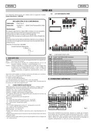
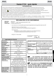
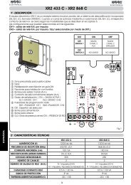
1. WARNINGSBefore attempting any work on the control board (connections, maintenance),always turn off power.Install, upstream of the system, a differential thermal breaker with adequatetripping threshold.Connect the earth cable to the appropriate terminal on the J7 connectorof the equipment (see fig.2).Always separate power cables from control and safety cables (push-button,receiver, photocells, etc.). To avoid any electric noise, use separatesheaths or a shielded cable (with earthed shield).CONTROL BOARD 740 D3. LAYOUT AND COMPONENTS2. TECHNICAL SPECIFICATIONSPower supply (+6% -10% V) 230 V~ - 50 Hz (115 V~ - 60 Hz*)Absorbed power 10 W (10 W*)Motor max. load 1000 W (1200 W*)Accessories max. load 0,5 A (0.5 A*)Operating ambient temperature-20 °C +55 °CProtection fuses 2 (see fig. 1)Automatic / “Stepped” automatic / Semi-automaticFunction logics/ Safety devices / Semi-automatic B/ Dead-man C / “Stepped” semi-automatic/ Mixed Log. B+CWork timeProgrammable (from 0 to 4 min.)Pause timeProgrammable (from 0 to 4 min.)Thrust forceAdjustable over 50 levelsOpen / Pàartial opening / Safety devicesTerminal board inputs at opng. / Safety devices at clsng. / Stop /Edge / Power supply + EarthOn-connector inputsOpening and closing limit-switches / EncoderFlashing lamp - Motor - 24 Vdc accessoriesTerminal board outputs power supply - 24 Vdc indicator-light / Timedoutput. - Fail safeRapid connector5-pin card connection for Minidec, Decoderor RP receiversProgramming3 keys (+, -, F) and display, “basic” or“advanced” modeBasic mode programmablefunctionsFunction logic - Pause time - Thrust Force- Gate directionTorque at initial thrust - Braking - Fail safe- Pre-flashing - Indicator-light/Timed output -Advanced mode programmablefunctionsOpening and closing safety devices logic -Encoder - Decelerations - Partial openingtime - Work time - Assistance request - CyclecounterDL SIGNALLING AND PROGRAMMING DISPLAYLed INPUTS STATUS CONTROL LEDJ1 LOW VOLTAGE TERMINAL BOARDJ2 CONNECTOR FOR DECODER/MINIDEC/RP RECEIVERJ3 ENCODER CONNECTORj4 CAPACITOR CONNECTORJ5 LIMIT -SWITCH CONNECTORJ6 MOTORS AND FLASHING LAMP CONNECTION TERMINAL BOARDJ7 POWER SUPPLY TERMINAL BOARD 230Vac (115Vac*)F1 MOTORS AND TRANSF. PRIMARY FUSE (F 5A) (F 10A*)F2 LOW VOLTAGE AND ACCESSORIES FUSE (T 800mA)F “F” PROGRAMMING PUSH-BUTTON- “–” PROGRAMMING PUSH-BUTTON+ “+” PROGRAMMING PUSH-BUTTON* 740D 115VFig. 1ENGLISH4. ELECTRIC CONNECTIONSJ4C*115 Vacmax 60w(According tothe selectedcontrol unit)230 V ~ / 50 Hzor115 v ~ / 60Hz(According tothe selectedcontrol unit)* Only if don’t use J4 connectorFig. 212