automated system 739 - Faac
automated system 739 - Faac automated system 739 - Faac
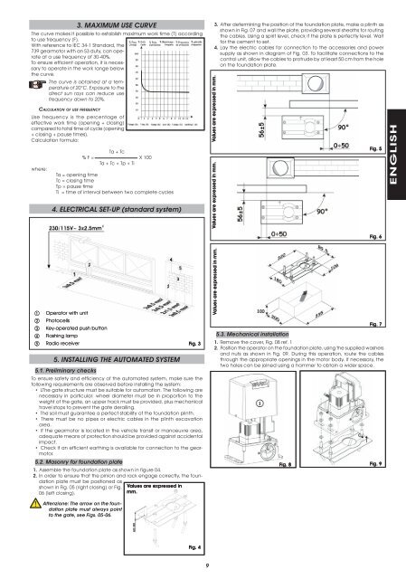
3. MAXIMUM USE CURVEThe curve makes it possible to establish maximum work time (T) accordingto use frequency (F).With reference to IEC 34-1 Standard, the739 gearmotor with an S3 duty, can operateat a use frequency of 30-40%.To ensure efficient operation, it is necessaryto operate in the work range belowthe curve.The curve is obtained at a temperatureof 20°C. Exposure to thedirect sun rays can reduce usefrequency down to 20%.CALCULATION OF USE FREQUENCYUse frequency is the percentage ofeffective work time (opening + closing)compared to total time of cycle (opening+ closing + pause times).Calculation formula:where:Ta + Tc% F = X 100Ta + Tc + Tp + TiTa = opening timeTc = closing timeTp = pause timeTi = time of interval between two complete cycles4. ELECTRICAL SET-UP (standard system)3.4.Values are expressed in mm.Values are expressed in mm.After determining the position of the foundation plate, make a plinth asshown in Fig. 07 and wall the plate, providing several sheaths for routingthe cables. Using a spirit level, check if the plate is perfectly level. Waitfor the cement to set.Lay the electric cables for connection to the accessories and powersupply as shown in diagram of Fig. 03. To facilitate connections to thecontrol unit, allow the cables to protrude by at least 50 cm from the holeon the foundation plate.Fig. 5ENGLISHFig. 6Operator with unitPhotocellsKey-operated push buttonFlashing lampRadio receiver5. INSTALLING THE AUTOMATED SYSTEMFig. 35.1. Preliminary checksTo ensure safety and efficiency of the automated system, make sure thefollowing requirements are observed before installing the system:• LThe gate structure must be suitable for automation. The following arenecessary in particular: wheel diameter must be in proportion to theweight of the gate, an upper track must be provided, plus mechanicaltravel stops to prevent the gate derailing.• The soil must guarantee a perfect stability of the foundation plinth.• There must be no pipes or electric cables in the plinth excavationarea.• If the gearmotor is located in the vehicle transit or manoeuvre area,adequate means of protection should be provided against accidentalimpact.• Check if an efficient earthing is available for connection to the gearmotor.5.2. Masonry for foundation plate1. Assemble the foundation plate as shown in figure 04.2. In order to ensure that the pinion and rack engage correctly, the foundationplate must be positioned asshown in Fig. 05 (right closing) or Fig.Values are expressed in06 (left closing).mm.Values are expressed in mm.Fig. 75.3. Mechanical installation1. Remove the cover, Fig. 08 ref. 12. Position the operator on the foundation plate, using the supplied washersand nuts as shown in Fig. 09. During this operation, route the cablesthrough the appropriate openings in the motor body. If necessary, thetwo holes can be joined using a hammer to obtain a wider space.Fig. 8 Fig. 9Attenzione: The arrow on the foundationplate must always pointto the gate, see Figs. 05-06.Fig. 49
- Page 3 and 4: INDICE1. DESCRIZIONE E CARATTERISTI
- Page 5 and 6: 3. CURVA DI MASSIMO UTILIZZOLa curv
- Page 7 and 8: 6.2. Posizionamento dei finecorsaPe
- Page 9: INDEX1. DESCRIPTION AND TECHNICAL S
- Page 14 and 15: There are no special applications.1
- Page 17 and 18: 3. COURBE D’UTILISATION MAXIMALEL
- Page 19 and 20: 6.2. Positionnement des fins de cou
- Page 21 and 22: ÍNDICE1. DESCRIPCIÓN Y CARACTERÍ
- Page 23 and 24: 3. CURVA DE MÁXIMA UTILIZACIÓNLa
- Page 26 and 27: 10. APLICACIONES ESPECIALESNo está
- Page 28 and 29: Die vorliegenden Anleitungen sind f
- Page 30 and 31: DEUTSCH3.Maße in mm.ie Höhe des G
- Page 32 and 33: 10. SONDERANWENDUNGENSonderanwendun
- Page 34 and 35: Deze aanwijzingen gelden voor de vo
- Page 36 and 37: 3.Maten uitgedrukt in mmStel de hoo
- Page 38 and 39: 10. BIJZONDERE TOEPASSINGENEr zijn
- Page 40: Le descrizioni e le illustrazioni d
3. MAXIMUM USE CURVEThe curve makes it possible to establish maximum work time (T) accordingto use frequency (F).With reference to IEC 34-1 Standard, the<strong>739</strong> gearmotor with an S3 duty, can operateat a use frequency of 30-40%.To ensure efficient operation, it is necessaryto operate in the work range belowthe curve.The curve is obtained at a temperatureof 20°C. Exposure to thedirect sun rays can reduce usefrequency down to 20%.CALCULATION OF USE FREQUENCYUse frequency is the percentage ofeffective work time (opening + closing)compared to total time of cycle (opening+ closing + pause times).Calculation formula:where:Ta + Tc% F = X 100Ta + Tc + Tp + TiTa = opening timeTc = closing timeTp = pause timeTi = time of interval between two complete cycles4. ELECTRICAL SET-UP (standard <strong>system</strong>)3.4.Values are expressed in mm.Values are expressed in mm.After determining the position of the foundation plate, make a plinth asshown in Fig. 07 and wall the plate, providing several sheaths for routingthe cables. Using a spirit level, check if the plate is perfectly level. Waitfor the cement to set.Lay the electric cables for connection to the accessories and powersupply as shown in diagram of Fig. 03. To facilitate connections to thecontrol unit, allow the cables to protrude by at least 50 cm from the holeon the foundation plate.Fig. 5ENGLISHFig. 6Operator with unitPhotocellsKey-operated push buttonFlashing lampRadio receiver5. INSTALLING THE AUTOMATED SYSTEMFig. 35.1. Preliminary checksTo ensure safety and efficiency of the <strong>automated</strong> <strong>system</strong>, make sure thefollowing requirements are observed before installing the <strong>system</strong>:• LThe gate structure must be suitable for automation. The following arenecessary in particular: wheel diameter must be in proportion to theweight of the gate, an upper track must be provided, plus mechanicaltravel stops to prevent the gate derailing.• The soil must guarantee a perfect stability of the foundation plinth.• There must be no pipes or electric cables in the plinth excavationarea.• If the gearmotor is located in the vehicle transit or manoeuvre area,adequate means of protection should be provided against accidentalimpact.• Check if an efficient earthing is available for connection to the gearmotor.5.2. Masonry for foundation plate1. Assemble the foundation plate as shown in figure 04.2. In order to ensure that the pinion and rack engage correctly, the foundationplate must be positioned asshown in Fig. 05 (right closing) or Fig.Values are expressed in06 (left closing).mm.Values are expressed in mm.Fig. 75.3. Mechanical installation1. Remove the cover, Fig. 08 ref. 12. Position the operator on the foundation plate, using the supplied washersand nuts as shown in Fig. 09. During this operation, route the cablesthrough the appropriate openings in the motor body. If necessary, thetwo holes can be joined using a hammer to obtain a wider space.Fig. 8 Fig. 9Attenzione: The arrow on the foundationplate must always pointto the gate, see Figs. 05-06.Fig. 49


