LEDA 12+6 - Artemide
LEDA 12+6 - Artemide
LEDA 12+6 - Artemide

Create successful ePaper yourself
Turn your PDF publications into a flip-book with our unique Google optimized e-Paper software.
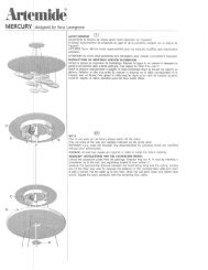
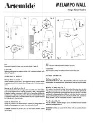
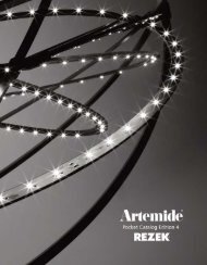
GFFig.1 Only for USA<strong>LEDA</strong> <strong>12+6</strong>design: Örni HalloweenEFHEFKGFHUKFig. 1UAvvertenze:Prima dell’installazionedell’apparecchio disinserirel’energia elettrica.Per la particolare complessitàdi assemblaggio delpresente lampadario, siconsiglia di far eseguire ilmontaggio a personalequalificatoAttenzione:Non deve essere superatala potenza massima indicata.Istruzioni dimontaggio.Figure n. 1 - - 2Fissare la piastra (EF)al soffitto utilizzando ifori più esterni. Separareil fondello (F)dalla squadretta (K).Fissare il fondello allapiastra (EF) utilizzandole quattro asolepraticate sullo stesso.Togliere il morsetto(G) dal cavo di sostegnoe allentare la vite(H) per togliere il cavodimessaaterraelasquadretta (K).Infilare il corpo in vetro(E), la ghiera (B), lacoppa (A), la coppa inmetallo (Z) elasquadretta(K).Far passare il cavo disostegno nel primoforo del morsetto (G)epoi nel ponticello delfondello (F). Regolarel’altezza della lampadae far passare poiil cavo negli altri duefori del morsetto (G)eserrare con forza.Avis:Avant d’installer l’appareil,couper le courant.À cause de la complexité del’assemblage du lustre- -ci,on conseille l’assistance dupersonnel qualifié.Attention:Ne pas surmonter la puissancemaximum indiquee.Instructions demontage.Figure n. 1 - - 2Fixer la plaque (EF) auplafond par les trous lesplus externes. Séparerle culot (F) de l’équerre(K). Fixer le culot à laplaque (EF) aumoyendes quatre boutonnièresfaites précédemment.Enlever la borne(G)ducåbledesoutienet desserrer la vis (H)defaçon à enlever le câblede mise à la terre etl’équerre (K).Insérer le corps deverre (E), le collier deserrage (B), la coupe(A), la coupe de métal(Z) et l’équerre (K).Fairepasserlecâbledesoutien dans le premiertrou de la borne (G).Ensuite le faire passerdans la passerelle duculot (F). Régler la hauteurde la lampe et fairepasser le cable dans lesautres deux trous de laborne (G). Le bloquerfortement.Note:Before installation, disconnectenergy.Due to difficulty in theassembling of the light fixturehere above, we suggestthe assistance of semiskilledpersonnel.Attention:Do not exceed max, ratedpower.Assemblyinstructions.Figure n. 1 - - 2Fix plate (EF)toceilingby external holes.Separate bottom plate(F) fromsquare(K).Fix bottom plate toplate (EF)bymeansofthe four loops theremade.Take out terminal strip(G) from supportingcable and loosenscrew (H) inordertoremove groundingcable and square (K).Insert glass body (E),threaded locking ring(B), cup (A), metal cup(Z) and square (K).Pass supporting cablethrough the first hole ofterminal strip (G) .Subsequently, throughengine- -tender fallplate of bottom plate(F). Adjust lamp heightand pass cablethrough the other twoholes of terminal strip(G). Block it tightly.Vorsicht:Vor der Installation desGerätes den Strom ausschalten.Die montage dieser Lampesollte durch Fachkräfteausgeführt werden, da derZusammenban besanderskompliziert ist.Achtung:Die angegebene höchsteLeistung darf nicht überschrittenwerden.Aufbaueinleitung.Bild Nr. 1 - - 2Die Platte (EF) andiedecke mittels der äußestenBohrungen befestigen.Den Wandkontakt(H) vondemWinkelstück(K) trennen.Den Wandkontaktdurch die sich auf demselbenbefindlichen 4Ösen an die Platte (EF)befestigen. DieKlemme (G) von demStutzkabel herausnehmenund die Schraube(H) zur Entfernung desErdungskabels unddes Winkelstückes (K)lockern. Den Glaskörper(E),dieZwinge(B),dieSchale(A) und dasWinkelstück (K) einfügen.Das Stutzkabelin das erste Loch derKlammer (G) und dannin das Schaltdraht desWandkontaktes (F)einführen.Die Höhe derLampe einstellen unddas Kabel dann in dieweiteren 2 Löcher derKlemme (G) einfûhrenund kräftig anziehen.Advertencia:Antes de instalar el aparato,desconectar la energiaelectrica.Por causa de la complexidaddel montaje de estalámparadetecho,seruegala asistencia de personalcalificado.Atencion:No Hay que superar lapotencia maxima indicata.Instruccionespara el montaje.Figura n. 1 - - 2Fijarlalámina(EF) altecho por los taladrosmás externos. Separarel casquillo (F) de laescuadra (K). Fijar elcasquillo a la láminapor medio de los cuatroojales hechos anteriormente.Quitar elborne (G) delcabledesostén y destornillar eltornillo (H) demaneraque se puede quitar elcable de puesta atierra. Introducir elcuerpo de vidrio (E), lavirola (B), la copa demetal (Z) ylaescuadra(K). Hacer pasar elcable de sostén en elprimer hueco delborne (G). Luegohacerlo pasar en elpuentecito delcasquillo (F). Regularla altura de la lámparay hacer pasar el câbleen los dos otros agujerosdel borne (G). Bloquearlofuertemente.Only for USANote:Before installation, disconnectenergy.Due to difficulty in theassembling of the light fixturehere above, we suggestthe assistance of semiskilledpersonnel.Attention:Do not exceed max, ratedpower.Instructions formounting to wallbox.Figure n. 1 - - 2Take out terminal strip (G)from supporting cableand loosen screw (H) inorder to remove groundingcableand square(K).Insert glass body (E),threaded locking ring (B),cup (A), metal cup (Z)andsquare (K). Make the electricalconnections by connectingthe WHITE wirefrom the fixture to theWHITE wire from the wallbox and the fixture BLACKwire to the BLACK wire.Also connect the GREENwire from plate to thesystem ground conductor.Fix plate (EF) towallbox. Fix bottom plate toplate (EF)bymeansofthefour loops there made.Pass supporting cablethrough the first hole ofterminal strip (G).Subsequently,through engine- -tender fall plate of bottomplate (F). Adjust lampheight and pass cablethrough the other twoholes of terminal strip (G).Block it tightly.
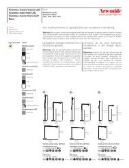
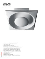
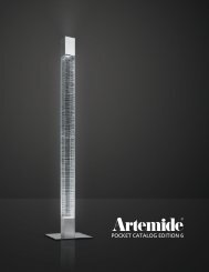
Fig. 2KZABEIl morsetto (G) deve La borne doit êtreessere posizionato placée aussi présil più vicino possibileque possible dual fondello per culot de façon qu’onpoter eseguire cor-peut réaliser lesrettamenteleopera-opérations suivan-zioni successive. tes. Brancher lesEseguire i collegamenticâbles provenants duelettrici dei cavi plafond à leurs bor-provenienti dal soffitto nes. Brancher lescon gli appositi morsetti.Collegare i caviprovenienti dalla lampadaai morsetti edalla vite di messa aterra. Riagganciare lasquadretta (K)ebloccarlacâbles provenants dela lampe aux bornes etàlavisdemiseàlaterre.Raccrocher l’équerre(K) et la bloquer aumoyen de la vis (U).con la vite (U). Enlever la rallongeSfilare la prolunga externe de façonesterna fino a farla qu’on peut la fairepassare nel foro della passer dans le trou desquadretta (K) e l’équerre (K)etlagardertenerla in posizioneen la même posi-riagganciando con la tion.Raccrocher lesua vite e rondella ilcavo di messa a terraprecedentementecable de mise à laterre (précédemmentdécroché) au moyensganciato. Portare de la vis et de la rondelle.fino contro al soffitto laPousser lacoppa (Z), la coppa(A) e bloccarla con laghiera (B).coupe (A) contre leplafond et la bloquerau moyen du collierde serrage (B).Terminal stripshould be placed asclose as possible tobottom plate inorder to carry outcorrectly the followingoperations.Connect cables proceedingfrom ceilingto suitable terminalstrips.Connect cables proceedingfrom lamp toterminal strips and togrounding screw.Clasp again square(K) and block it bymeans of (U) screw.Slip out externalextensioninordertopass it throughsquare hole (K).Keep it in that positionand clasp againgrounding cable bymeans of screw andwasher.Push cup (A) againstceiling and block it bymeans of threadedlocking ring (B).DIe Klammer (G)muß dem Basisstückam nächsten liegen,damit man korrektdann weiterarbeitenkann. Die elektrischenAnschlüsse dervon der Decke kommendenKabel mitden entsprechendenKlammern vornehmen.Dieaus derLampe kommendenKabel mit den Klammernund mit derErdungsschraubeverbinden. Das Winkelstück(K) wiederanhängen und es mitder Schraube (U)befestigen. Dasäussere Verlängerungskabelherausnehmen,es in dasWinkelstückloch (K)einführen und es ander Stelle halten,indem man das imvoraus abgehakteErdungskabel durchseine Schraube wiederanhängt.Die Schale (A) dichtgegen die Decke haltenund sie durch dieNutmutter (B) befestigen.El borne (G) tieneque estar posicionadolo más cercanoposible del casquillode manera que sepueden efectuar lasoperacionessiguientes. Conectarlos cables procedentesdel techo a susbornes. Conectar loscables procedentesde la lámpara a losbornes y al tornillo depuesta a tierra. Reengancharla escuadra(K) y bloquearla pormedio del tornillo (U).Quitar la prolongaexterna de maneraquesepuedehacerlapasar en el hueco dela escuadra (K) yguardarla en la mismaposición. Reengancharel cable de puestaa tierra por mediodel tornillo y de laarandela. Empujar lacopa (A) contra eltecho y bloquearla pormediodelavirola(B).Terminal stripshould be placed ascloseaspossibletobottom plate in orderto carry out correctlythe followingoperations.Connect cables proceedingfrom lamp toterminal strips and togrounding screw.Clasp again square(K) and block it bymeans of (U) screw.Slip out externalextension in order topass it through squarehole (K).Keep it in that positionand clasp againgrounding cable bymeans of screw andwasher.Push cup (A) againstceiling and block it bymeans of threadedlocking ring (B).
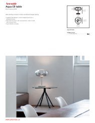
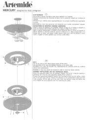
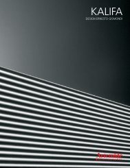
Fig. 3NONL* non presente nellaversione ”LATTIMO”L*CDIMNRQSWFig. 4CVDOFigura n. 3 - - 4 - - 5Fissare i 6 bracci piccoli(O) sul supporto (N)bloccandoli con dadi erondelle. Eseguire i collegamentielettrici agliappositi morsettisecondo quanto indicatosul supportostesso. Calzare le coppettepiccole (C) suibracci (O) e bloccarlecon le ghiere (V). Infilaresulla tige (I) la coppa inmetallo (L) e la coppa invetro (M). Infilare la partein vetro (N) sul tubetto(D), inserirli sulla tige (I)e bloccare avvitandomoderatamente ildischetto (P). Avvitaresulla tige (I) il dischetto(Q) in modo che rimangano1o2mmdalpianodella parte in vetro (N).Montare il supportobracci (R)conlemorsettiererivolte verso ilbasso, il distanziale (S)ebloccare con rondella edado (W).Attenzione: prima diserrare a fondo controllareche rispetto aibracci già montati, i foridel supporto (R) sianonella posizione desiderata.Figure n. 3 - - 4 - - 5Fixer les 6 petits bras (O)sur le support (N) enlesbloquant à l’aided’écrous et de rondelles.Effectuer les connexionsélectriques aux bornescorrespondantes suivantles indications situéessur le support. Caler lespetites cloches (C) surlebras (O)etlesbloqueraumoyen des bagues (V).Enfiler sur la tige la clocheen métal (L)etlaclocheen verre (M). Enfilerla partie en verre (N) surle tube (D), les introduiresur la tige (I) etbloqueren vissant légèrement ledisque (P). Visser ledisque (Q) surlatige(I)de façon à ce qu’il reste 1ou 2 mm par rapport auplan de la partie en verre(N). Monter le support àbras (R) avec les barrettesde raccordementorientées vers le bas,l’entretoise (S), puis bloqueravec la rondelle etl’écrou (W).Attention: avant de serrerà fond, contrôler queles trous du support (R)soient dans la positionsouhaitée par rapportaux bras déjà montés.PFigure n. 3 - - 4 - - 5Fix the 6 small arms (O)on the support (N),securing them with nutsand washers. Make theelectrical connectionsto the terminals providedas indicated onthe support itself. Fit thesmall cups (C) onto thearms (O) and securethem with the ring- -nuts (V). Fit the metalcup (L) andtheglasscup (M) onto the stem(I). Fit the glass part (N)on to the pipe (D), fitthem onto the stem (I)and fix by moderatelytightening the disc (P).Screw the disc (Q)ontothe stem (I) so that theyare1or2mmfromthesurface of the glasssection (N). Fit the armsupport (R)withtheterminalboards facingdown, and the spacer(S), and secure withwasher and nut (W).Caution: before tighteningfully, check thatthe holes in the support(R) are in the requiredposition in relation tothe arms already fitted.Abbildung 3--4-- 5Die 6 kleinen Arme (O)ander Halterung (N) befestigenund mit den Mutternund Scheiben festschrauben.Die elektrischenKabel an dieKlemme schließen, wiean der Halterung selbstangezeigt. Die kleinenschalen (C) aufdieArme(O) montieren und mitden Nutmuttern (V) blockieren.Auf den Stab (I)dieMetallschale(L) unddie Glasschale (M)anbringen. Das Glasteil(N) auf das Röhrchen (D)stecken; das Ganze aufden Stab (I) setzenunddurchdasPlättchen(P)leicht festschrauben. AmStab (I) das plättchen (Q)so festschrauben, daßnoch1bis2mmbiszurGlasfläche (N) frei bleiben.Die Armhalterung(R) mit den klemmennach unten gerichtet unddas Distanzstück montierenund mit der Scheibeund der Mutter (W) festschrauben.Achtung: vor dem Festschraubenkontrollieren,ob im Verhältnis zu denschon montieren Armen,die Halterungslöcher (R)in der gewünschten Positionliegen.Figura n. 3 - - 4 - - 5Fijar los 6 brazospequeños (O) sobre elsoporte (N) ybloquearloscontuercasyarandelas.Efectuar las conexioneseléctricasalosbor-nes correspondientesconforme a lo indicadoen el propio soporte.Colocar las copaspequeñas (C) sobrelosbrazos (O) ybloquearlascon los anillos (V). Introducirsobre la barra (V)lacopa de metal (L) y lacopa de vidrio (M). Insertarla parte de vidrio (N)sobre el tubito (D), introducirlossobre la barra (I)y bloquear enroscandoligeramente el disco (P).Enroscar el disco (Q)sobre la barra (I) demanera que queden 1 o 2mm hasta el plano de laparte de vidrio (N). Montarel soporte de brazos(R)conlasbarrasdebornesorientadas haciaabajo, el distanciador(S), y bloquear con arandelay tuerca (W).Atención: antes de apretara fondo, comprobarque los agujeros delsoporte (R) estén en laposición deseadarespecto a los brazos yamontados.Fig. 5Figure n. 3 - - 4 - - 5Fix the 6 small arms (O)on the support (N),securing them with nutsand washers. Make theelectrical connectionsto the terminals providedas indicated onthe support itself. Fit thesmall cups (C) onto thearms (O) and securethem with the ring- -nuts(V). Fit the metal cup (L)and the glass cup (M)onto the stem (I). Fit theglass part (N) ontothepipe (D), fit them ontothe stem (I) andfixbymoderately tighteningthe disc (P). Screw thedisc (Q) onto the stem(I) so that they are 1 or 2mm from the surface ofthe glass section (N). Fitthe arm support (R)withthe terminal boards facingdown, and thespacer (S), and securewith washer and nut(W).Caution: before tighteningfully, check thatthe holes in the support(R) are in the requiredposition in relation tothe arms already fitted.
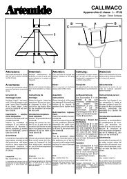
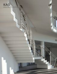
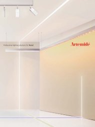
Fig. 6Fig. 7DECDABBCCDSREY*Y* non presentenellaversione ”LATTIMO”CODEJTCDFig. 8XFigura n. 6 - - 7 - - 8Eseguire i collegamentielettrici dei cavi provenientidallo stelo al morsettoed alla vite di messaa terra bloccandoli poisotto al pressacavo piùvicino (fig. 6). Fissare i 12bracci (CD) al supporto(R) bloccandoli con dadie rondelle. Eseguire i collegamentielettrici agliappositi morsettisecondo quanto indicatosul supporto stesso. Calzarele coppette grandi(DE) sui bracci bloccandolecon i distanziali(BC) e le ghiere (AB).ATTENZIONE: I vetri diFigure n. 6 - - 7 - - 8Connecter les câblesprovenants de la tige à laborneetàlavisdemiseà terre, puis les bloquersous le serre- -câbles leplus proche (fig. 6). Fixerles12bras(CD) ausupport(R) etlesbloqueràl’aide d’écrous et de rondelles.Effectuer les connexionsélectriques auxbornes correspondantessuivant les indicationssituées sur le support.Caler les grandes cloches(DE) surlesbrasetles bloquer au moyendes entretoises (BC) etdes bagues (AB).ATTENTION: les piècesen verre de ce lustre étantfabriquées à la main,elles peuvent avoir despoids différents. Pourobtenir l’équilibre, disposerles cloches (DE) defaçon à ce que les pluslourdes compensent lesplus légères ou bien fairetourner le support (R)jusqu’à trouver la positionoptimale. Positionner lejoint en caoutchouc àl’intérieur de la cloche(J), introduire dedans lacloche métallique (V) etquesto lampadarioessendo lavorati a manopossono avere pesi differentitra loro; Per il correttobilanciamentodisporre le coppe (DE)inmodochelepiúpesantivadano a compensareeventuali mancanzeoppure ruotare il supporto(R) finoatrovarelaposizione ottimale. Posizionarela guarnizione ingomma (T) all’internodella coppa (J), alloggiareal suo interno lacoppa metallica (Y) eposizionare il tutto sul positionner le tout surdistanziale (S). Avvitare ilpomello (X).l’entretoise (S). Visser lapoignée (X).Lampadine:Max6x60W(E14)+Max 12 x 60 W (E 14)Ampoules:Max6x60W(E14)+Max 12 x 60 W (E 14)Figure n. 6 - - 7 - - 8Make the electrical connectionsof the cableleading from the rod tothe terminal and theearth screw, and thensecure them under thenearest cable clamp (fig.6). Fix the 12 arms (CD)to the support (R),securing them with nutsand washers. Make theelectrical connections tothe terminals providedas indicated on the supportitself. Fit the largecups (DE) tothearms,securing them with thespacers (BC) and thering- -nuts (AB).CAUTION: Since theglass parts of this chandelierare hand processed,their weightsmay not be identical. Tobalance them correctly,arrange the cup (DS) sothat the heaviest compensatefor any shortfalls,or turn the support(R) until the optimumposition is obtained.Place the rubber seal (T)inside the cup (J), placethe metal cup (Y) insideit and place all parts onthe spacer (S). Tightenthe knob (X).Bulbs:Max6x60W(E14)+Max 12 x 60 W (E 14)Abbildung 6--7--8Die Kabel vom Leuchteran die Klemme und dieErdung anschließen undmit einem naheliegendenKabeldurchgang befestigen(Abb. 6). Die 12 Arme(CD) an der Halterung (R)befestigen und mit denMuttern und Scheiben.Elektrische Anschlüsse anden entsprechendenKlemmen vornehmen, wiean der Halterung selbstangezeigt. Die großenSchalen (DE)aufdieArmesetzen und mit denDistanzstücken (BC) unden Nutmuttern (AB)befestigen.ACHTUNG: die Schalendieser Lampe sind alle vonHAnd hergestellt undkönnen auch unterschiedlichschwer sein. Um dasGewicht der Schalen (DE)auszugleichen, die schwerenSchalen so montieren,daß sie das Gewicht deranderen ausgleichen oderdie Halterung (R)drehenbis die optimale Positionerreicht ist. Die Gummidichtung(T) im Innerender Schale (J) anbringen,indieseSchaledieMetallschale(Y) fügen und dasGanze auf dasDistanzstück (S) positionieren.Mit dem Kugelgriff(X) festschrauben.Glühlampen:Max6x60W(E14)+Max 12 x 60 W (E 14)Figura n. 6 - - 7 - - 8Efectuar las conexioneseléctricas de los cablesprovenientes de la barraal borne y al tornillo depuesta a tierra, y bloquearlosdespués alaislador pasapanel máscercano (fig. 6). Fijar los12 brazos (CD) alsoporte (R) bloqueándoloscontuercasyarandelas.Efectuar las conexioneseléctricasalosbor-nes correspondientesconforme a lo indicadoen el propio soporte.Colocar las copas grandes(DE) sobre los brazosybloquearlasconlosdistanciadores (BC)ylasarandelas (AB).ATENCIÓN: al estar trabajadosa mano, losdistintos cristales de estalámpara de techo puedentener pesos diferentes.Para conseguir unequilibrio correcto, colocarlas copas (DE) deforma que las más pesadasvayan a compensarposibles desequilibrios,o bien girar el soporte (R)hasta hallar la posiciónóptima. Colocar la juntade goma (T) dentrodelacopa (J), encajar en suinterior la copa metálica(V) y poner todo estegrupo sobre el distanciador(S). Enroscar laperilla (X).Bombillas:Max6x60W(E14)+Max 12 x 60 W (E 14)Attenzione: La sicurezza elettrica di questo apparecchio è garantita con l’uso appropriato di queste istruzioni. Pertanto è necessario conservarle.Attention: La securitè de l’appareil n’est garantie que si les instructions sont convenablement suivies.Il est donc necessaire de les conserver.Attention: This equipment is guarantieed only when used as indicated in these instructions. Therefore they should be kept for future reference.Achtung: Die Sicherheit der Leuchte wird nur bei sachgerechtem Gebrauch gemäss Anweisungen gewährleistet. Bitte bewahren Sie diese sorgfältig auf.Atencion: La seguridad del aparato está garantizada solo con el uso apropriado de las instrucciones. Por lo tanto es necesario conservarlas.Figure n. 6 - - 7 - - 8Make the electrical connectionsof the cableleading from the rod tothe terminal and theearth screw, and thensecure them under thenearest cable clamp (fig.6). Fix the 12 arms (CD)to the support (R), securingthem with nuts andwashers. MAke the electricalconnections to theterminals provided asindicated on the supportitself. Fit the large cups(DE) to the arms, securingthem with thespacers (BC) and thering- -nuts (AB).CAUTION: Since theglass parts of this chandelierare hand processed,their weightsmay not be identical. Tobalance them correctly,arrange the cup (DS) sothat the heaviest compensatefor any shortfalls,or turn the support(R) until the optimumposition is obtained.Place the rubber seal (T)inside the cup (J), placethe metal cup (Y) insideit and place all parts onthe spacer (S). Tightenthe knob (X).Bulbs:Max6x60W(E12)+Max 12 x 60 W (E 12)In caso di reclamo citare il numeroEn cas de réclamation, veuillez citer le numéroIn case of complaint, please quote numberBei jeder Reklamation geben Sie, bitte folgende Nummer anEn caso de reclamacion indicar el númerocod. Y503000196Divisione di ARTEMIDE spavia Bergamo, 18- -20010 Pregnana Milanese (Milano)- -ITALIAtel:93.51.81- -(a ricerca automatica)telefax 02/93.59.02.54- -93.59.04.96sito internet http://www.ARTEMIDE.COMcodice fiscale e partita I.V.A. 00846890150