CS® 1400/2000 - Peavey
CS® 1400/2000 - Peavey
CS® 1400/2000 - Peavey
- No tags were found...

Create successful ePaper yourself
Turn your PDF publications into a flip-book with our unique Google optimized e-Paper software.
CS ® <strong>1400</strong>/<strong>2000</strong> Power Amplifier Owner's ManualFor more information on other great <strong>Peavey</strong> products, visit your local <strong>Peavey</strong> dealer or go online to www.peavey.com
Intended to alert the user to the presence of uninsulated “dangerous voltage” within the product’senclosure that may be of sufficient magnitude to constitute a risk of electric shock to persons.Intended to alert the user of the presence of important operating and maintenance (servicing)instructions in the literature accompanying the product.CAUTION: Risk of electrical shock — DO NOT OPEN!CAUTION: To reduce the risk of electric shock, do not remove cover. No user serviceable parts inside.Refer servicing to qualified service personnel.WARNING: To prevent electrical shock or fire hazard, this apparatus should not be exposed to rain ormoisture‚ and objects filled with liquids‚ such as vases‚ should not be placed on this apparatus. Beforeusing this apparatus‚ read the operating guide for further warnings.Este símbolo tiene el propósito, de alertar al usuario de la presencia de “(voltaje) peligroso” sinaislamiento dentro de la caja del producto y que puede tener una magnitud suficiente como paraconstituir riesgo de descarga eléctrica.Este símbolo tiene el propósito de alertar al usario de la presencia de instruccones importantes sobre laoperación y mantenimiento en la información que viene con el producto.PRECAUCION: Riesgo de descarga eléctrica ¡NO ABRIR!PRECAUCION: Para disminuír el riesgo de descarga eléctrica, no abra la cubierta. No hay piezas útilesdentro. Deje todo mantenimiento en manos del personal técnico cualificado.ADVERTENCIA: Para prevenir choque electrico o riesgo de incendios, este aparato no se debe exponer ala lluvia o a la humedad. Los objetos llenos de liquidos, como los floreros, no se deben colocar encimade este aparato. Antes de usar este aparato, lea la guia de funcionamiento para otras advertencias.Ce symbole est utilisé dans ce manuel pour indiquer à l’utilisateur la présence d’une tension dangereusepouvant être d’amplitude suffisante pour constituer un risque de choc électrique.Ce symbole est utilisé dans ce manuel pour indiquer à l’utilisateur qu’il ou qu’elle trouvera d’importantesinstructions concernant l’utilisation et l’entretien de l’appareil dans le paragraphe signalé.ATTENTION: Risques de choc électrique — NE PAS OUVRIR!ATTENTION: Afin de réduire le risque de choc électrique, ne pas enlever le couvercle. Il ne se trouveà l’intérieur aucune pièce pouvant être reparée par l’utilisateur. Confiez I’entretien et la réparation del’appareil à un réparateur <strong>Peavey</strong> agréé.AVIS: Dans le but de reduire les risques d’incendie ou de decharge electrique, cet appareil ne doitpas etre expose a la pluie ou a l’humidite et aucun objet rempli de liquide, tel qu’un vase, ne doitetre pose sur celui-ci. Avant d’utiliser de cet appareil, lisez attentivement le guide fonctionnant pouravertissements supplémentaires.Dieses Symbol soll den Anwender vor unisolierten gefährlichen Spannungen innerhalb des Gehäuseswarnen, die von Ausreichender Stärke sind, um einen elektrischen Schlag verursachen zu können.Dieses Symbol soll den Benutzer auf wichtige Instruktionen in der Bedienungsanleitung aufmerksammachen, die Handhabung und Wartung des Produkts betreffen.VORSICHT: Risiko — Elektrischer Schlag! Nicht öffnen!VORSICHT: Um das Risiko eines elektrischen Schlages zu vermeiden, nicht die Abdeckung enfernen.Es befinden sich keine Teile darin, die vom Anwender repariert werden könnten. Reparaturen nur vonqualifiziertem Fachpersonal durchführen lassen.WARNUNG: Um elektrischen Schlag oder Brandgefahr zu verhindern, sollte dieser Apparat nichtRegen oder Feuchtigkeit ausgesetzt werden und Gegenstände mit Flüssigkeiten gefuellt, wie Vasen,nicht auf diesen Apparat gesetzt werden. Bevor dieser Apparat verwendet wird, lesen Sie bitte denFunktionsführer für weitere Warnungen.2
IMPORTANT SAFETY INSTRUCTIONSWARNING: When using electrical products, basic cautions should always be followed, including the following:1. Read these instructions.2. Keep these instructions.3. Heed all warnings.4. Follow all instructions.5. Do not use this apparatus near water.6. Clean only with a dry cloth.7. Do not block any of the ventilation openings. Install in accordance with manufacturer’s instructions.8. Do not install near any heat sources such as radiators, heat registers, stoves or other apparatus (including amplifiers)that produce heat.9. Do not defeat the safety purpose of the polarized or grounding-type plug. A polarized plug has two blades with onewider than the other. A grounding type plug has two blades and a third grounding plug. The wide blade or third prong isprovided for your safety. If the provided plug does not fit into your outlet, consult an electrician for replacement of theobsolete outlet.10. Protect the power cord from being walked on or pinched, particularly at plugs, convenience receptacles, and the pointthey exit from the apparatus.11. Only use attachments/accessories provided by the manufacturer.12. Use only with a cart, stand, tripod, bracket, or table specified by the manufacturer, or sold with the apparatus. When acart is used, use caution when moving the cart/apparatus combination to avoid injury from tip-over.13. Unplug this apparatus during lightning storms or when unused for long periods of time.14. Refer all servicing to qualified service personnel. Servicing is required when the apparatus has been damaged in anyway, such as power-supply cord or plug is damaged, liquid has been spilled or objects have fallen into the apparatus,the apparatus has been exposed to rain or moisture, does not operate normally, or has been dropped.15. Never break off the ground pin. Write for our free booklet “Shock Hazard and Grounding.” Connect only to a powersupply of the type marked on the unit adjacent to the power supply cord.16. If this product is to be mounted in an equipment rack, rear support should be provided.17. Note for UK only: If the colors of the wires in the mains lead of this unit do not correspond with the terminals in yourplug‚ proceed as follows:a) The wire that is colored green and yellow must be connected to the terminal that is marked by the letter E‚ the earthsymbol‚ colored green or colored green and yellow.b) The wire that is colored blue must be connected to the terminal that is marked with the letter N or the color black.c) The wire that is colored brown must be connected to the terminal that is marked with the letter L or the color red.18. This electrical apparatus should not be exposed to dripping or splashing and care should be taken not to place objectscontaining liquids, such as vases, upon the apparatus.19. Exposure to extremely high noise levels may cause a permanent hearing loss. Individuals vary considerably in susceptibilityto noise-induced hearing loss, but nearly everyone will lose some hearing if exposed to sufficiently intense noisefor a sufficient time. The U.S. Government’s Occupational Safety and Health Administration (OSHA) has specified thefollowing permissible noise level exposures:Duration Per Day In HoursSound Level dBA, Slow Response8 906 924 953 972 1001 1⁄2 1021 1051⁄2 1101⁄4 or less 115According to OSHA, any exposure in excess of the above permissible limits could result in some hearing loss. Ear plugs or protectors tothe ear canals or over the ears must be worn when operating this amplification system in order to prevent a permanent hearing loss, ifexposure is in excess of the limits as set forth above. To ensure against potentially dangerous exposure to high sound pressure levels, it isrecommended that all persons exposed to equipment capable of producing high sound pressure levels such as this amplification system beprotected by hearing protectors while this unit is in operation.SAVE THESE INSTRUCTIONS!3
WICHTIGE SICHERHEITSHINWEISEACHTUNG: Beim Einsatz von Elektrogeräten müssen u.a. grundlegende Vorsichtsmaßnahmen befolgt werden:1. Lesen Sie sich diese Anweisungen durch.2. Bewahren Sie diese Anweisungen auf.3. Beachten Sie alle Warnungen.4. Befolgen Sie alle Anweisungen.5. Setzen Sie dieses Gerät nicht in der Nähe von Wasser ein.6. Reinigen Sie es nur mit einem trockenen Tuch.7. Blockieren Sie keine der Lüftungsöffnungen. Führen Sie die Installation gemäß den Anweisungen des Herstellers durch.8. Installieren Sie das Gerät nicht neben Wärmequellen wie Heizungen, Heizgeräten, Öfen oder anderen Geräten (auch Verstärkern),die Wärme erzeugen.9. Beeinträchtigen Sie nicht die Sicherheitswirkung des gepolten Steckers bzw. des Erdungssteckers. Ein gepolter Stecker weistzwei Stifte auf, von denen einer breiter ist als der andere. Ein Erdungsstecker weist zwei Stifte und einen dritten Erdungsstift auf.Der breite Stift bzw. der dritte Stift dient Ihrer Sicherheit. Sollte der beiliegende Stecker nicht in Ihre Steckdose passen, wendenSie sich bitte an einen Elektriker, um die ungeeignete Steckdose austauschen zu lassen.10. Schützen Sie das Netzkabel, sodass niemand darauf tritt oder es geknickt wird, insbesondere an Steckern oder Buchsen undihren Austrittsstellen aus dem Gerät.11. Verwenden Sie nur die vom Hersteller erhältlichen Zubehörgeräte oder Zubehörteile.12. Verwenden Sie nur einen Wagen, Stativ, Dreifuß, Träger oder Tisch, der den Angaben des Herstellers entspricht oder zusammenmit dem Gerät verkauft wurde. Wird ein Wagen verwendet, bewegen Sie den Wagen mit dem darauf befindlichen Gerät besondersvorsichtig, damit er nicht umkippt und möglicherweise jemand verletzt wird.13. Trennen Sie das Gerät während eines Gewitters oder während längerer Zeiträume, in denen es nicht benutzt wird, von derStromversorgung.14. Lassen Sie sämtliche Wartungsarbeiten von qualifizierten Kundendiensttechnikern durchführen. Eine Wartung ist erforderlich,wenn das Gerät in irgendeiner Art beschädigt wurde, etwa wenn das Netzkabel oder der Netzstecker beschädigt wurden,Flüssigkeit oder Gegenstände in das Gerät gelangt sind, das Gerät Regen oder Feuchtigkeit ausgesetzt wurde, nicht normalarbeitet oder heruntergefallen ist.15. Der Erdungsstift darf nie entfernt werden. Auf Wunsch senden wir Ihnen gerne unsere kostenlose Broschüre „Shock Hazard andGrounding“ (Gefahr durch elektrischen Schlag und Erdung) zu. Schließen Sie nur an die Stromversorgung der Art an, die amGerät neben dem Netzkabel angegeben ist.16. Wenn dieses Produkt in ein Geräte-Rack eingebaut werden soll, muss eine Versorgung über die Rückseite eingerichtet werden.17. Hinweis – Nur für Großbritannien: Sollte die Farbe der Drähte in der Netzleitung dieses Geräts nicht mit den Klemmen in IhremStecker übereinstimmen, gehen Sie folgendermaßen vor:a) Der grün-gelbe Draht muss an die mit E (Symbol für Erde) markierte bzw. grüne oder grün-gelbe Klemme angeschlossenwerden.b) Der blaue Draht muss an die mit N markierte bzw. schwarze Klemme angeschlossen werden.c) Der braune Draht muss an die mit L markierte bzw. rote Klemme angeschlossen werden.18. Dieses Gerät darf nicht ungeschützt Wassertropfen und Wasserspritzern ausgesetzt werden und es muss darauf geachtetwerden, dass keine mit Flüssigkeiten gefüllte Gegenstände, wie z. B. Blumenvasen, auf dem Gerät abgestellt werden.19. Belastung durch extrem hohe Lärmpegel kann zu dauerhaftem Gehörverlust führen. Die Anfälligkeit für durch Lärm bedingtenGehörverlust ist von Mensch zu Mensch verschieden, das Gehör wird jedoch bei jedem in gewissem Maße geschädigt, der übereinen bestimmten Zeitraum ausreichend starkem Lärm ausgesetzt ist. Die US-Arbeitsschutzbehörde (Occupational and HealthAdministration, OSHA) hat die folgenden zulässigen Pegel für Lärmbelastung festgelegt:Dauer pro Tag in StundenGeräuschpegel dBA, langsame Reaktion8 906 924 953 972 1001 1 ⁄2 1021 1051⁄2 1101⁄4 oder weniger 115Laut OSHA kann jede Belastung über den obenstehenden zulässigen Grenzwerten zu einem gewissen Gehörverlust führen. Solltedie Belastung die obenstehenden Grenzwerte übersteigen, müssen beim Betrieb dieses Verstärkungssystems Ohrenstopfen oderSchutzvorrichtungen im Gehörgang oder über den Ohren getragen werden, um einen dauerhaften Gehörverlust zu verhindern. Um sich voreiner möglicherweise gefährlichen Belastung durch hohe Schalldruckpegel zu schützen, wird allen Personen empfohlen, die mit Gerätenarbeiten, die wie dieses Verstärkungssystem hohe Schalldruckpegel erzeugen können, beim Betrieb dieses Geräts einen Gehörschutz zu tragen.BEWAHREN SIE DIESE SICHERHEITSHINWEISE AUF!4
INSTRUCTIONS IMPORTANTES DE SECURITEATTENTION: L’utilisation de tout appareil électrique doit être soumise aux precautions d’usage incluant:1. Lire ces instructions.2. Gardez ce manuel pour de futures références.3. Prétez attention aux messages de précautions de ce manuel.4. Suivez ces instructions.5. N’utilisez pas cette unité proche de plans d’eau.6. N’utilisez qu’un tissu sec pour le nettoyage de votre unité.7. N’obstruez pas les systèmes de refroidissement de votre unité et installez votre unité en fonction des instructionsde ce manuel.8. Ne positionnez pas votre unité à proximité de toute source de chaleur.9. Connectez toujours votre unité sur une alimentation munie de prise de terre utilisant le cordon d’alimentationfourni.10. Protégez les connecteurs de votre unité et positionnez les cablages pour éviter toutes déconnexions accidentelles.11. N’utilisez que des fixations approuvées par le fabriquant.12. Lors de l’utilsation sur pied ou pole de support, assurez dans le cas de déplacement de l’ensemble enceinte/support de prévenir tout basculement intempestif de celui-ci.13. Il est conseillé de déconnecter du secteur votre unité en cas d’orage ou de durée prolongée sans utilisation.14. Seul un technicien agréé par le fabriquant est à même de réparer/contrôler votre unité. Celle-ci doit être contrôlée sielle a subit des dommages de manipulation, d’utilisation ou de stockage (humidité,…).15. Ne déconnectez jamais la prise de terre de votre unité.16. Si votre unité est destinée a etre montée en rack, des supports arriere doivent etre utilises.17. Note pour les Royaumes-Unis: Si les couleurs de connecteurs du cable d’alimentation ne correspond pas au guidede la prise secteur, procédez comme suit:a) Le connecteur vert et jaune doit être connectrer au terminal noté E, indiquant la prise de terre ou correspondantaux couleurs verte ou verte et jaune du guide.b) Le connecteur Bleu doit être connectrer au terminal noté N, correspondnat à la couleur noire du guide.c) Le connecteur marron doit être connectrer au terminal noté L, correspondant à la couleur rouge du guide.18. Cet équipement électrique ne doit en aucun cas être en contact avec un quelconque liquide et aucun objetcontenant un liquide, vase ou autre ne devrait être posé sur celui-ci.19. Une exposition à de hauts niveaux sonores peut conduire à des dommages de l’écoute irréversibles. La susceptibilitéau bruit varie considérablement d’un individu à l’autre, mais une large majorité de la population expérienceraune perte de l’écoute après une exposition à une forte puissance sonore pour une durée prolongée. L’organisme dela santé américaine (OSHA) a produit le guide ci-dessous en rapport à la perte occasionnée:Durée par Jour (heures)Niveau sonore moyen (dBA)8 906 924 953 972 1001 1 ⁄2 1021 1051⁄2 1101⁄4 ou inférieur 115D’après les études menées par le OSHA, toute exposition au delà des limites décrites ce-dessus entrainera des pertes de l’écoute chez laplupart des sujets. Le port de système de protection (casque, oreilette de filtrage,…) doit être observé lors de l’opération cette unité ou desdommages irréversibles peuvent être occasionnés. Le port de ces systèmes doit être observé par toutes personnes susceptibles d’être exposéesà des conditions au delà des limites décrites ci-dessus.GARDEZ CES INSTRUCTIONS!5
INSTRUCCIONES IMPORTANTES PARA SU SEGURIDADCUIDADO: Cuando use productos electrónicos, debe tomar precauciones básicas, incluyendo las siguientes:1. Lea estas instrucciones.2. Guarde estas instrucciones.3. Haga caso de todos los consejos.4. Siga todas las instrucciones.5. No usar este aparato cerca del agua.6. Limpiar solamente con una tela seca.7. No bloquear ninguna de las salidas de ventilación. Instalar de acuerdo a las instrucciones del fabricante.8. No instalar cerca de ninguna fuente de calor como radiadores, estufas, hornos u otros aparatos (incluyendo amplificadores)que produzcan calor.9. No retire la patilla protectora del enchufe polarizado o de tipo “a Tierra”. Un enchufe polarizado tiene dos puntas, una deellas más ancha que la otra. Un enchufe de tipo “a Tierra” tiene dos puntas y una tercera “a Tierra”. La punta ancha (latercera ) se proporciona para su seguridad. Si el enchufe proporcionado no encaja en su enchufe de red, consulte a unelectricista para que reemplaze su enchufe obsoleto.10. Proteja el cable de alimentación para que no sea pisado o pinchado, particularmente en los enchufes, huecos, y los puntosque salen del aparato.11. Usar solamente añadidos/accesorios proporcionados por el fabricante.12. Usar solamente un carro, pie, trípode, o soporte especificado por el fabricante, o vendido junto al aparato. Cuando se useun carro, tenga cuidado al mover el conjunto carro/aparato para evitar que se dañe en un vuelco. No suspenda esta caja deninguna manera.13. Desenchufe este aparato durante tormentas o cuando no sea usado durante largos periodos de tiempo.14. Para cualquier reparación, acuda a personal de servicio cualificado. Se requieren reparaciones cuando el aparato ha sidodañado de alguna manera, como cuando el cable de alimentación o el enchufe se han dañado, algún líquido ha sidoderramado o algún objeto ha caído dentro del aparato, el aparato ha sido expuesto a la lluvia o la humedad, no funciona demanera normal, o ha sufrido una caída.15. Nunca retire la patilla de Tierra.Escríbanos para obtener nuestro folleto gratuito “Shock Hazard and Grounding” (“Peligrode Electrocución y Toma a Tierra”). Conecte el aparato sólo a una fuente de alimentación del tipo marcado al lado del cablede alimentación.16. Si este producto va a ser enracado con más equipo, use algún tipo de apoyo trasero.17. Nota para el Reino Unido solamente: Si los colores de los cables en el enchufe principal de esta unidad no correspondencon los terminales en su enchufe‚ proceda de la siguiente manera:a) El cable de color verde y azul debe ser conectado al terminal que está marcado con la letra E‚ el símbolo de Tierra(earth)‚ coloreado en verde o en verde y amarillo.b) El cable coloreado en azul debe ser conectado al terminal que está marcado con la letra N o el color negro.c) El cable coloreado en marrón debe ser conectado al terminal que está marcado con la letra L o el color rojo.18. Este aparato eléctrico no debe ser sometido a ningún tipo de goteo o salpicadura y se debe tener cuidado para no ponerobjetos que contengan líquidos, como vasos, sobre el aparato.19. La exposición a altos niveles de ruido puede causar una pérdida permanente en la audición. La susceptibilidad a la pérdidade audición provocada por el ruido varía según la persona, pero casi todo el mundo perderá algo de audición si se exponea un nivel de ruido suficientemante intenso durante un tiempo determinado. El Departamento para la Salud y para laSeguridad del Gobierno de los Estados Unidos (OSHA) ha especificado las siguientes exposiciones al ruido permisibles:Duración por Día en Horas Nivel de Sonido dBA, Respuesta Lenta8 906 924 953 972 1001 1 ⁄2 1021 1051⁄2 1101⁄4 o menos 115De acuerdo al OSHA, cualquier exposición que exceda los límites arriba indicados puede producir algún tipo de pérdida en la audición.Protectores para los canales auditivos o tapones para los oídos deben ser usados cuando se opere con este sistema de sonido para preveniruna pérdida permanente en la audición, si la exposición excede los límites indicados más arriba. Para protegerse de una exposición aaltos niveles de sonido potencialmente peligrosa, se recomienda que todas las personas expuestas a equipamiento capaz de producir altosniveles de presión sonora, tales como este sistema de amplificación, se encuentren protegidas por protectores auditivos mientras esta unidadesté operando.GUARDE ESTAS INSTRUCCIONES!6
ENGLISHCS ® <strong>1400</strong>/<strong>2000</strong>Power AmplifiersCongratulations on your purchase of a <strong>Peavey</strong> CS Series power amplifier! Designed for years of reliable operation, CS Seriesamplifiers offer the sonic superiority and unsurpassed reliability for which <strong>Peavey</strong> is famous in a rugged, compact unit.Advanced technologies and extensive protection circuitry allow operation with greater efficiency, even under difficult loads andpower conditions. The exclusive DDT (Distortion Detection Technique) circuit ensures trouble-free operation into loads as lowas 2 ohms, protects speakers and ensures sonic integrity even in extreme overload conditions. <strong>Peavey</strong>’s high-efficiency designuses tunnel-cooled heat sinks and dual-speed DC fans for consistent lower overall operating temperature, resulting in longeroutput transistor life.<strong>Peavey</strong> CS Series amplifiers are simple to operate and housed in ultra-strong steel chassis, but improper use can bedangerous. Some CS Series amplifiers are very high powered and can put out high voltages and sizable currents at frequenciesup to 30 kHz. Always use safe operating techniques with these amplifiers.FOR YOUR SAFETY, READ THE IMPORTANT PRECAUTIONS SECTION, AS WELL AS INPUT, OUTPUT AND POWERCONNECTION SECTIONS.UnpackingUpon unpacking, inspect the amplifier. If you find any damage, notify your supplier immediately. Only the consignee(the supplier from whom you purchased the amplifier) may institute a claim with the carrier for damage incurredduring shipping. Be sure to save the carton and all packing materials. Should you ever need to ship the unit back to<strong>Peavey</strong> or one of its offices, service centers or the supplier, use only the original factory packing. If the shipping cartonis unavailable, contact <strong>Peavey</strong> to obtain a replacement.MountingCS Series amplifiers will mount in standard 19" racks. Rear mounting ears are also provided for additional support,which is recommended in non-permanent installations like mobile or touring sound systems. Because of the cablesand connectors on the rear panel, a right angle or offset screwdriver or hex key will make it easier to fasten the rearmounting ears to the rails.Cooling RequirementsCS Series amplifiers use a forced-air cooling system to maintain a low, consistent operating temperature. Air is drawninto the amplifier by fans on the back panel and courses through the cooling fins of the tunnel-configured channelheat sinks, then exhausts through the front panel grilles. If either heat sink gets too hot, a sensing circuit will mutethe signal for that particular channel. It is important to have an air inlet at the back of the amplifier to allow coolingair to enter. If the amp is rack mounted, do not use doors or covers on the back of the rack, as the intake air mustflow without resistance. Make sure that there is one (1) standard rack space opening for every three mounted poweramplifiers.7
IntroductionOperating PrecautionsMake sure the mains voltage is correct and the same as that printed on the rear of the amplifier. Damage caused byconnecting the amplifier to improper AC voltage is not covered by any CS ® Series warranty. See the Connecting Powersection for more information on voltage requirements.Note: Always turn off and disconnect the amplifier from mains voltage before making audio connections. Also, as anextra precaution, have the attenuators turned down during power-up.Before powering up, turn the attenuator controls down to prevent speaker damage if there is a high signal level at theinputs. Always use high-quality input and speaker cables to ensure trouble-free operation. Most intermittent problemsare caused by faulty cables.Consult the Wire Gauge Charts (page 9) to determine proper gauges for differing load impedances and cable lengths.Remember that cable resistance robs amplifier power in two ways: power lost directly to resistance (I 2 R loss) and bylowering the total load impedance. Also make sure the mode switch is correctly set for the desired application. Seesections on Stereo, Parallel and Bridged Mono Operation for more information.Connecting InputsInput connections are made via the three-pin XLR (pin 2+) or 6.3 mm plug “combi” connectors on the rear panel of theamplifier. The inputs are actively balanced and the overload point is high enough to accept the maximum output levelof virtually any signal source.Connecting OutputsAll models have two output (speaker) connections per channel. Cables can be connected with banana plugs, spadelugs, or bare wire to the five-way binding posts. The preferred connection method is via the Speakon ® connectors. Pinconnections are noted on the rear panel.Connecting PowerCS Series amplifier power requirements are rated at 1/8 power (typical music conditions) and 1/3 power (extrememusic conditions). The maximum power current draw rating is limited only by the front panel circuit breaker. Consultthe specifications in the Appendices section for figures on the current that each amplifier will demand. Unlessotherwise specified when ordered, <strong>Peavey</strong> amplifiers shipped to customers are configured as follows:North America - 120VAC/60HzEurope, Asia, Australia - 230/240VAC/60-50HzSouth America - 120VAC/60Hz or 240VAC/50HzNote: Always turn off and disconnect the amplifier from mains voltage before making audio connections. As an extraprecaution, have the attenuators turned down while powering up.8
Wire Guage ChartsStranded Cable Lgth.(ft.)Wire Gauge (AWG)Power Loss(8 ohm load)Power Loss(4 ohm load)Power Loss(2 ohm load)518161412100.81%0.510.320.200.1281.61%1.020.640.400.253.2%2.01.280.800.511018161412101.61%1.020.640.400.253.2%2.01.280.800.516.2%4.02.51.601.0140181614121086.2%4.02.51.601.010.6011.9%7.75.03.22.01.2022%14.69.66.24.02.4801816141210811.9%7.75.03.22.01.2022%14.69.66.24.02.437%2617.811.87.74.7Stranded Cable Lgth.(m)Wire Gauge (mm 2 )Power Loss(8 ohm load)Power Loss(4 ohm load)Power Loss(2 ohm load)20.30.50.751.52.542.9%1.741.160.580.350.225.6%3.42.31.160.700.4410.8%6.74.52.31.390.8750.50.751.52.5464.3%2.91.450.870.550.378.2%5.62.91.741.090.7315.5%10.85.63.42.21.45100.50.751.52.5468.24%5.62.91.741.090.7315.5%10.85.62.91.741.0928%19.910.86.74.32.9300.751.52.5461015.5%8.25.13.22.21.3125%15.59.86.34.32.645%2818.212.08.25.19
Operation ModesStereo OperationFor stereo (dual channel) operation, turn the amplifier OFF and set the mode select switches on the back panel to theout (extended) position. In this mode, both channels operate independently of each other, with their input attenuatorscontrolling their respective levels. Thus, a signal at channel A’s input produces an amplified signal at channel A’soutput, while a signal at channel B’s input produces an amplified signal at channel B’s output.Bridged Mono OperationBoth amplifier channels can be bridged together to make a very powerful single-channel monaural amplifier. Useextreme caution when operating in the bridged mode; potentially lethal voltage may be present at the outputterminals. To bridge the amplifier, depress the rear panel Bridge switch to the IN position. Direct the signal to channelA’s input and connect the speakers across the hot outputs (the “+” binding posts) of channels A and B. Only channelA’s input attenuator is active while in Bridge Mono mode.Unlike the stereo mode, in which one side of each output is at ground, both sides are hot in bridged mode. Channel A’sside is the same polarity as its input with the minimum nominal load impedance being 4 ohms (equivalent to drivingboth channels at 2 ohms) in bridged mode. Driving bridged loads of less than 4 ohms will activate the DDT circuitry(see Indicators section), resulting in a loss of power, and may also cause a thermal (overheating) overload.10
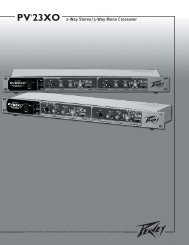
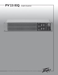
Front Panel1 2 2Rear PanelSwitches & Controls3 4AC Power Switch/Circuit Breaker (1)The CS ® Series amplifiers feature a combination AC switch/circuit breaker on the front panel. If the switch shuts offduring normal use, push it back to the ON position once. If the switch will not stay in the ON position, the amplifierneeds servicing.Input Attenuators (2)Whenever possible, set the attenuators fully clockwise to maintain optimum system headroom. The input attenuatorcontrols (one for channel A, one for channel B) located on the front panel attenuate signal level (decrease gain) for therespective amplifier channels in all modes. See the specifications at the end of this manual for standard voltage gainand input sensitivity information.Bridge Select Switch (3)The rear panel Bridge Select switch determines if the amplifier is in stereo (two channels) or in Bridged Mono mode.Do not operate the Bridge Select switch with the amplifier powered on. See the sections on Stereo and Bridged Monomode for more information.DDT Defeat Switch (4)For normal operation, the DDT circuit should remain operational by leaving the DDT Defeat Switch in the extendedposition. This will prevent excessive distortion and potential speaker damage.11
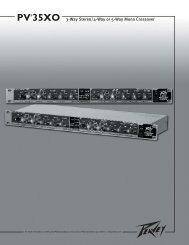
Front Panel211233IndicatorsCS ® Series amplifiers feature three front panel LED indicators per channel: PWR (power), SIG (signal) and DDT (DistortionDetection Technique). These LED indicators inform the user of each channel’s operating status and warn of possible abnormalconditions.PWR LED (1)The Power LED indicates that the channel is operational. It illuminates under normal operation and remains on evenwhen the channel’s DDT circuit is activated.SIG LED (2)The Signal LED illuminates when its channel produces an output signal of greater than 1 volt RMS or 25 mV inputwith a O dB attenuation of the front panel knobs. This is useful in determining whether a signal is reaching and beingamplified by the amplifier. If the Signal LED is illuminated but no sound is present, that means a signal is present atthe amplifier but a problem may exist after the amplifier, such as in the cables or speakers.DDT LED (3)A channel’s DDT LED will illuminate at the onset of clipping. If the LEDs are flashing quickly and intermittently, thechannel is just at the clip threshold, while a steady, bright glow means the amp is clip limiting, or reducing gain toprevent severely clipped waveforms from reaching the speakers. See Distortion Detection Technique Limiting underthe Protection Features section for more information.12
Protection FeaturesThe <strong>Peavey</strong> CS Series incorporates several circuits to protect the amplifier and speakers under virtually any situation. <strong>Peavey</strong>has made the amplifiers as foolproof as possible by making them immune to short and open circuits, mismatched loads,DC voltage and overheating. If a channel goes into the DDT gain reduction mode, the DDT LED illuminates. The clippingpercentage or output power is instantly reduced. When a problem occurs that causes a channel to go into a protection mode,the PWR (Power) LED for that channel will turn off. DC voltage on the output or excessive subsonic frequencies will cause thetriac crowbar circuit to activate to protect the speakers. If the amplifier overheats, the signal will be removed from the channelthat is at fault until the amplifier cools down, thus protecting the amplifier.Distortion Detection Technique (DDT) LimitingAny time a channel is driven into hard, continuous clipping, the DDT circuit will automatically reduce the channel gainto a level just slightly into clipping, guarding the speakers against the damaging, high-power, continuous squarewaves that may be produced. Situations that may activate the DDT circuit include uncontrolled feedback, oscillations,an improper equipment setting or malfunction upstream from the amplifier. Normal program transients will not triggerDDT; only steady, excessive clipping will cause the DDT LED to illuminate.LFC Impedance SensingCS Series amplifiers feature innovative circuitry for safe operation into any load. When an amplifier senses a load thatoverstresses the output stage, the Load Fault Correction circuit adjusts the channel gain to a safe level. Extreme loadfault under high power levels will cause the signal to be muted for the associated channel. This method of outputstageprotection is far more effective than the standard limiting found on conventional power amplifiers. The LFCcircuit is sonically transparent in normal use and unobtrusive when activated.Thermal ProtectionThe internal fans will keep the amplifier operating well within its intended temperature range under all normalconditions. If a channel’s heat sink temperature reaches 85° C (which may indicate an obstructed air supply), thatchannel will independently protect itself by muting its input signal and shut down until it has cooled. During this time,the PWR LED will go out and the cooling fans will continue operating at high speed.Short CircuitIf an output is shorted, the LFC and thermal circuits will automatically protect the amplifier. The LFC circuit sensesthe short circuit as an extremely stressful load condition and attenuates the signal, protecting the channel’s outputtransistors from over-current stress. If the short circuit remains, the channel will eventually thermally protect itself bymuting the input signal.DC Voltage ProtectionIf an amplifier channel detects DC voltage or subsonic frequencies at its output terminals, the output triac crowbarcircuitry will activate immediately to prevent speaker damage.Turn-On/Turn-Off ProtectionUpon powering up, the amplifier stays in Protect mode, muting the input signal for approximately four seconds whilethe power supplies charge and stabilize. Also, when power is removed, the input signals are muted so that no thumpsor pops are heard.13
Speaker ProtectionAll loudspeakers have electrical, thermal and physical limits that must be observed to prevent damage or failure. Excessivepower, low frequencies applied to high frequency drivers, severely clipped waveforms and DC voltage can all be fatal to coneand compression drivers. <strong>Peavey</strong> CS ® Series amplifiers automatically protect speakers from DC voltages and subsonic signals.If using an electronic crossover, be extremely careful that the low and mid bands are connected to the correct amplifiers anddrivers and not to those designed for a higher frequency band. An amplifier’s clipping point is its maximum peak output power,and some of the higher powered <strong>Peavey</strong> CS Series amplifiers can deliver more power than many speakers can safely handle. Besure the peak power capability of the amplifier is not excessive for your speaker system. For more information, see the sectionon Protection Features.Fuses may also be used to limit power to speaker drivers, although as current-limiting rather than voltage-limiting devices, theyare an imperfect solution, and as the weakest links, they only limit once before needing replacement. Some poor-quality fuseshave a significant series resistance that could degrade the amplifier’s damping of the speaker’s motion and may even deterioratethe system’s sound quality. If you elect to use fuses, check with the speaker manufacturer to determine the proper currentrating and time lag required.Do not drive any low frequency speaker enclosure with frequencies lower than its own tuned frequency; the reduced acousticaldamping could cause a ported speaker to bottom out even at moderate power. Consult the speaker system specifications todetermine its frequency limits.Amplifier Maintenance and User ResponsibilityA CS Series amplifier requires no routine maintenance and should not need internal adjustment during its lifetime. Your CSSeries amplifier is very powerful and can be potentially dangerous to loudspeakers and humans alike. It is your responsibilityto read the Important Precautions section and to make sure that the amplifier is installed, wired and operated properly asinstructed in this manual. Many loudspeakers can be easily damaged or destroyed by overpowering, especially with the highpower available from a bridged amplifier. Read the Speaker Protection section and always be aware of the speaker’s continuousand peak power capabilities.Service / Warranty InformationIn the unlikely event that your amplifier develops a problem, it must be returned to an authorized distributor, service center orshipped directly to our factory. To obtain service, contact your nearest <strong>Peavey</strong> Service Center, Distributor, Dealer, or any of theworldwide <strong>Peavey</strong> offices. For contact information, reach <strong>Peavey</strong> Inc. Customer Service directly:Telephone: 601-483-5365 (USA)Fax Number: 601-486-1278 (USA)For technical inquiries only, the <strong>Peavey</strong> Technical Services department can be faxed at 601-486-1361 (USA)Because of the complexity of the design and risk of electrical shock, all repairs must be performed only by qualified technicalpersonnel. If the unit needs to be shipped back to the factory, it must be sent in its original carton. It is the responsibility of theperson shipping the unit to properly package the amplifier. If you need a product shipping carton, please contact <strong>Peavey</strong> for areplacement.Please visit the <strong>Peavey</strong> website at: http://www.peavey.com.14
CS ® <strong>1400</strong>/<strong>2000</strong>Power AmplifiersSPECIFICATIONSCS <strong>1400</strong> CS <strong>2000</strong>Rated Power 4 ohms bridged 1,400 watts @ 1 kHz
CS ® <strong>1400</strong>/<strong>2000</strong>Power AmplifiersSPECIFICATIONSCrosstalk> -74 dB, “A” weighted referenced torated 4 ohm powerCurrent Draw @ 1/8 Power 745 watts @ 2 ohms, 505 watts @4 ohms, 325 watts @ 8 ohmsCurrent Draw @ 1/3 Power 1,930 watts @ 2 ohms, 1,235 watts @4 ohms, 815 watts @ 8 ohmsCoolingTwo 80 mm DC fans, dual speedoperationControls2 front panel attenuators, rear panelmode switch, rear panel DDT switchIndicator LEDs2 DDT/clipping, 2 Status/Power,2 SignalProtectionTemp, DC, turn-on transients, subsonic,improper load or shortsConnectors Combi XLR & 6.3 mm input, Speakon ®and Binding Post speaker output, IECmains connectorConstruction16 ga. steel with cast aluminum frontpanel and steel grilleDimensions88.9 mm x 482.6 mm x 376.3 mm+ 31.8 mm for rear support earsand connectors(3.5" x 19” x 14.81” + 1.25”)(+1.5” for handle depth)CS <strong>1400</strong> CS <strong>2000</strong>> -60 dB, “A” weighted referenced torated 4 ohm power1,090 watts @ 2 ohms, 745 watts@ 4 ohms, 445 watts @ 8 ohms2,715 watts @ 2 ohms, 1765 watts@ 4 ohms, 1,155 watts @ 8 ohmsTwo 80 mm DC fans, dual speedoperation2 front panel attenuators, rear panelmode switch, rear panel DDT switch2 DDT/clipping, 2 Status/Power,2 SignalTemp, DC, turn-on transients, subsonic,improper load or shortsCombi XLR & 6.3 mm input, Speakon ®and Binding Post speaker output, IECmains connector16 ga. steel with cast aluminum frontpanel and steel grille88.9 mm x 482.6 mm x 376.3 mm+ 31.8 mm for rear support earsand connectors(3.5” x 19" x 14.81” + 1.25”)(+ 1.5” for handle depth)Gross Weight 36.3 lbs. (16.46 kg.) 41.6 lbs. (18.87 kg.)Net Weight 32.7 lbs. (14.83 kg.) 36.3 lbs. (16.46 kg.)16
DEUTSCHCS ® <strong>1400</strong>/<strong>2000</strong>EndstufenHerzlichen Glückwunsch zum Kauf einer Endstufe der CS Series von <strong>Peavey</strong>! Die Verstärker der CS Series wurden füreinen zuverlässigen Betrieb und lange Lebensdauer entwickelt. In einem robusten, kompakten Gerät bieten sie dieüberragende Schallleistung und die unübertroffene Zuverlässigkeit, für die <strong>Peavey</strong> bekannt ist. Fortschrittliche Technologienund umfassende Schutzschaltungen ermöglichen einen effizienteren Betrieb auch bei problematischen Lasten undEnergiebedingungen. Die exklusive DDT -Schaltung (Distortion Detection Technique) gewährleistet einen störungsfreienBetrieb auch bei niedrigen Lasten bis zu 2 Ohm, schützt die Lautsprecher und gewährleistet ungestörte Schallleistungselbst unter extremer Überlastung. Die hochleistungsfähigen <strong>Peavey</strong>-Produkte sind mit tunnelgekühlten Kühlkörpern undGleichstromlüftern mit zweistufiger Drehzahl für kontinuierlich niedrigere allgemeine Betriebstemperatur ausgestattet, was dieLebensdauer des Endstufen-Transistors verlängert.Obwohl die Verstärker der <strong>Peavey</strong> CS Series relativ einfach zu bedienen und in ultrastarken Stahlgehäusenuntergebracht sind, birgt ihr unsachgemäßer Einsatz Gefahren. Einige Verstärker der CS Series sindHochleistungsverstärker, die hohe Spannungen und Ströme mit Frequenzen bis zu 30 kHz abgeben können. Achten Siebeim Einsatz dieser Verstärker immer auf sichere Betriebsverfahren.LESEN SIE SICH BITTE DIE ABSCHNITTE ÜBER WICHTIGE SICHERHEITSHINWEISE SOWIE ÜBER EINGANG, AUSGANG UNDSTROMANSCHLUSS DURCH, UM IHRE SICHERHEIT ZU GEWÄHRLEISTEN.AuspackenUntersuchen Sie den Verstärker beim Auspacken. Sollten Sie Beschädigungen feststellen, informieren Sie unverzüglichIhren Händler. Nur der Empfänger (der Händler, bei dem Sie das Gerät gekauft haben) kann gegenüber demSpediteur einen Anspruch aufgrund von Transportschäden geltend machen. Heben Sie den Karton und sämtlichesVerpackungsmaterial bitte auf. Sollte es irgendwann einmal erforderlich sein, das Gerät zu <strong>Peavey</strong> oder zu einemunserer Büros, Kundendienstzentren oder Händler zurückzuschicken, verwenden Sie dazu bitte ausschließlich dieOriginal-Werksverpackung. Sollte keine Versandverpackung mehr vorhanden sein, bitten Sie <strong>Peavey</strong> um Ersatz.MontageDie Verstärker der CS Series werden in genormten 19”-Racks montiert. Zur zusätzlichen Verstärkung sindMontageösen auf der Rückseite angebracht; dies wird für vorübergehende Installationen wie etwa mobile oder Tour-Beschallungssysteme empfohlen. Aufgrund der Kabel und Anschlüsse auf der Rückseite wird die Befestigung derhinteren Montageösen an den Schienen durch einen rechtwinkligen Schraubendreher, einen Winkelschraubendreheroder einen Sechskantschlüssel erleichtert.KühlanforderungenDie Verstärker der CS Series arbeiten mit einem Fremdkühlsystem, das eine niedrige gleichmäßige Betriebstemperaturgewährleistet. Luft wird durch Lüfter auf der Rückseite in den Verstärker eingesaugt, läuft durch die Kühlrippender tunnelartigen Kanalkühlkörper und wird durch das Gitter an der Vorderseite wieder abgegeben. Wird einer derKühlkörper zu heiß, schaltet seine Sensorschaltung das Signal für diesen jeweiligen Kanal stumm. An der Rückseitedes Verstärkers muss ein Lufteinlass zum Einsaugen der Kühlluft gelassen werden. Wird der Verstärker im Rackmontiert, darf das Rack hinten nicht mit Türen oder Abdeckungen verschlossen werden. Die Zuluft muss unbehindertströmen können. Zudem muss sichergestellt werden, dass eine (1) Standard-Rack-Höhe für jeweils drei montierteEndstufen offen bleibt.17
EinleitungSicherheitshinweise für den BetriebAchten Sie darauf, dass die Netzspannung korrekt ist und mit den Angaben auf der Rückseite des Verstärkersübereinstimmt. Schäden, die aufgrund des Anschlusses des Verstärkers an eine ungeeignete Wechselspannungentstehen, werden nicht von der CS ® -Series-Garantie abgedeckt. Nähere Informationen zur erforderlichen Spannungfinden Sie im Abschnitt Netzanschluss.Hinweis: Schalten Sie den Verstärker immer aus und trennen Sie ihn vom Netz, bevor Sie Audiogeräte anschließen. Alszusätzliche Vorsichtsmaßnahme sollten Sie vor dem Einschalten die Dämpfer herunterdrehen.Drehen Sie vor dem Einschalten die Dämpfer herunter, um eine Beschädigung der Lautsprecher zu vermeiden,falls an den Eingängen hohe Signalpegel vorliegen sollten. Verwenden Sie immer hochwertige Eingangs- undLautsprecherkabel, um einen störungsfreien Betrieb zu gewährleisten. Die meisten Probleme durch Ausfälle werdendurch defekte Kabel verursacht.Die geeigneten Durchmesser für verschiedene Lastimpedanzen und Kabellängen finden Sie in denKabelstärkentabellen (Seite 9). Denken Sie daran, dass der Kabelwiderstand die Leistung des Verstärkers aufzweifache Weise beeinträchtigt: Durch direkten Leistungsverlust aufgrund des Widerstands (I 2 R-Verlust) und durchVerringerung der Gesamtlastimpedanz. Achten Sie zudem darauf, dass der Modusschalter für die gewünschteAnwendung korrekt eingestellt ist. Näheres dazu finden Sie in den Abschnitten Stereo-, Parallel- und Bridged-Mono-Betrieb.Anschluss der EingängeDie Eingangsanschlüsse erfolgen über die 3-poligen XLR- (Stift 2+) oder 6,3-mm-Kombi-Buchsen auf der Rückseitedes Verstärkers. Die Eingänge sind aktiv symmetriert und der Überlastpunkt ist hoch genug, sodass der maximaleAusgangspegel nahezu jeder Signalquelle toleriert wird.Anschluss der AusgängeAlle Modelle sind mit zwei Ausgangsanschlüssen (Lautsprecheranschlüssen) pro Kanal ausgestattet. Die Kabel könnenmittels Bananenstecker, Greifer oder blankem Draht an die Fünfwege-Anschlussklemmen angeschlossen werden.Empfohlen wird der Anschluss über die Speakon ® -Buchsen. Die Anschlussbelegung ist auf der Rückseite angegeben.NetzanschlussDer Leistungsbedarf der Verstärker der CS Series ist auf 1/8 (übliche Musikbedingungen) und 1/3 (extremeMusikbedingungen) ausgelegt. Der Nennwert der Starkstromaufnahme wird nur über den Leistungsschalter aufder Vorderseite begrenzt. Den Strombedarf der jeweiligen Verstärker können Sie den technischen Daten im Anhangentnehmen. Wenn bei Bestellung nicht anders angegeben, werden die an die Kunden versandten <strong>Peavey</strong>-Verstärkerfolgendermaßen konfiguriert:Nordamerika - 120VAC/60HzEuropa, Asien, Australien - 230/240VAC/60-50HzSüdamerika - 120VAC/60Hz oder 240VAC/50HzHinweis: Schalten Sie den Verstärker immer aus und trennen Sie ihn vom Netz, bevor Sie Audiogeräte anschließen. Alszusätzliche Vorsichtsmaßnahme sollten Sie vor dem Einschalten die Dämpfer herunterdrehen.18
KabelstärkentabellenStranded Cable Lgth.(ft.)Wire Gauge (AWG)Power Loss(8 ohm load)Power Loss(4 ohm load)Power Loss(2 ohm load)518161412100.81%0.510.320.200.1281.61%1.020.640.400.253.2%2.01.280.800.511018161412101.61%1.020.640.400.253.2%2.01.280.800.516.2%4.02.51.601.0140181614121086.2%4.02.51.601.010.6011.9%7.75.03.22.01.2022%14.69.66.24.02.4801816141210811.9%7.75.03.22.01.2022%14.69.66.24.02.437%2617.811.87.74.7Stranded Cable Lgth.(m)Wire Gauge (mm 2 )Power Loss(8 ohm load)Power Loss(4 ohm load)Power Loss(2 ohm load)20.30.50.751.52.542.9%1.741.160.580.350.225.6%3.42.31.160.700.4410.8%6.74.52.31.390.8750.50.751.52.5464.3%2.91.450.870.550.378.2%5.62.91.741.090.7315.5%10.85.63.42.21.45100.50.751.52.5468.24%5.62.91.741.090.7315.5%10.85.62.91.741.0928%19.910.86.74.32.9300.751.52.5461015.5%8.25.13.22.21.3125%15.59.86.34.32.645%2818.212.08.25.119
BetriebsmodiStereobetriebFür den Stereobetrieb (mit zwei Kanälen) schalten Sie den Verstärker aus und stellen die Moduswahlschalter aufder Rückseite auf die ausgerastete (herausgezogene) Position. In diesem Modus arbeiten beide Kanäle unabhängigvoneinander, wobei ihre jeweiligen Pegel über die Eingangsdämpfer geregelt werden. Ein Signal am Eingang vonKanal A erzeugt somit ein verstärktes Signal am Ausgang von Kanal A, während ein Signal am Eingang von Kanal B einverstärktes Signal am Ausgang von Kanal B erzeugt.Bridged-Mono-BetriebBeide Verstärkerkanäle können gebrückt werden, um einen äußerst leistungsfähigen Mono-Verstärker mit einem Kanaleinzurichten. Gehen Sie beim Betrieb im Bridged-Modus mit äußerster Vorsicht vor, da an den Ausgangsklemmenmöglicherweise tödliche Spannung vorliegen kann. Zum Brücken des Verstärkers drücken Sie den Bridge-Schalterauf der Rückseite in die Position IN. Schließen Sie das Signal an den Eingang von Kanal A an, und schließen Siedie Lautsprecher über die spannungsführenden Ausgänge (die „+“-Anschlussklemmen) der Kanäle A und B an. ImBridged-Mono-Betrieb ist nur der Eingangsdämpfer von Kanal A aktiv.Anders als beim Stereo-Modus, bei dem eine Seite jedes Ausgangs geerdet ist, sind im Bridged-Modus beide Seitenspannungsführend. Die Seite von Kanal A hat dieselbe Polarität wie sein Eingang, wobei die Mindestnennlastimpedanzim Bridged-Modus 4 Ohm beträgt (was dem Betrieb beider Kanäle bei 2 Ohm entspricht). Durch das Treibengebrückter Lasten von unter 4 Ohm wird die DDT-Schaltung aktiviert (siehe Abschnitt Anzeigen), was zu einemLeistungsverlust führt und eine Wärmeüberlastung (Überhitzung) zur Folge haben kann.20
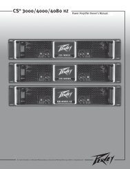
VORDERSEITE211233ANZEIGENDie Verstärker der CS ® Series sind mit drei LED-Anzeigen pro Kanal auf der Vorderseite ausgestattet: PWR (Power), SIG(Signal) und DDT (Distortion Detection Technique). Die LED-Anzeigen informieren den Anwender über den Betriebsstatus desjeweiligen Kanals und warnen vor möglichen Störungen.PWR-LED (1)Die Power-LED zeigt an, dass das Gerät in Betrieb ist. Sie leuchtet beim Normalbetrieb sowie auch bei aktivierter DDT-Schaltung des Kanals auf.SIG-LED (2)Die Signal-LED leuchtet auf, wenn der zugehörige Kanal bei einer Dämpfung der Knöpfe auf der Vorderseite von 0 dBein Ausgangssignal von über 1 V RMS oder 25 mV erzeugt. Hiermit lässt sich einfacher ermitteln, ob ein Signal denVerstärker erreicht und von ihm verstärkt wird. Leuchtet die Signal-LED, ohne dass etwas zu hören ist, liegt zwar einSignal am Verstärker vor, aber hinter dem Verstärker, z.B. in den Kabeln oder Lautsprechern, besteht eine Störung.DDT-LED (3)Die DDT-LED eines Kanals leuchtet beim Einsetzen von Clipping auf. Blinken die LEDs rasch und intermittierend,befindet sich der Kanal an der Schwelle zum Clipping. Leuchten sie kontinuierlich und hell auf, grenzt der Verstärkerdas Clipping ein oder verringert die Verstärkung um zu verhindern, dass stark gekappte Wellenformen dieLautsprecher erreichen. Weitere Informationen dazu finden Sie unter Schutz durch Distortion Detection Technique imAbschnitt Schutzfunktionen.22
SCHUTZFUNKTIONENDie <strong>Peavey</strong> CS Series ist mit verschiedenen Schaltungen ausgestattet, durch die Verstärker und Lautsprecher in nahezujeder Situation geschützt werden. <strong>Peavey</strong> hat die Verstärker so narrensicher wie möglich und dazu unempfindlich gegenüberKurzschluss, Leerlauf, ungeeigneten Lasten, Gleichspannung und Überhitzung gemacht. Schaltet ein Kanal in den DDT-Modus zur Gain-Verringerung, leuchtet die DDT-LED auf. Clipping-Prozentsatz oder Ausgangsleistung werden jedoch sofortverringert. Tritt ein Problem auf, das den Schutzmodus eines Kanals aktiviert, erlischt die PWR-LED (Power) für diesen Kanal.Durch Gleichspannung am Ausgang oder zu starke Unterschallfrequenzen wird der Zweiwege-Überspannungsschutz aktiviert,um die Lautsprecher zu schützen. Ist der Verstärker überhitzt, wird das Signal aus dem betroffenen Kanal herausgenommen,bis sich der Kanal abkühlt, um den Verstärker zu schützen.Schutz durch Distortion Detection Technique (DDT)Wird ein Kanal angesteuert, bis hartes kontinuierliches Clipping erfolgt, verringert die DDT-Schaltung automatisch dieVerstärkung des Kanals auf einen Pegel knapp unter der Clipping-Schwelle, sodass die Lautsprecher vor den starkenkontinuierlichen Rechteckwellen geschützt sind, die erzeugt werden und Schaden verursachen können. Situationen, indenen die DDT-Schaltung aktiviert werden kann, sind u.a. unkontrolliertes Feedback, Schwingungen, unsachgemäßeEinstellung der Ausrüstung oder Störungen in den vor dem Verstärker angeschlossenen Geräten. Die DDT-Schaltungwird nicht durch normale Programmspitzen ausgelöst, die DDT-LED leuchtet nur bei kontinuierlichem, übermäßigemClipping auf.LFC-ImpedanzermittlungDie Verstärker der CS Series sind mit einer innovativen Schaltung für einen sicheren Betrieb bei jeder Lastausgestattet. Liegt an einem Verstärker eine Last vor, die die Endstufe überlastet, korrigiert die Load-Fault-Correction-Schaltung die Kanalverstärkung auf einen sicheren Pegel. Extreme Fehllast bei hohen Leistungspegeln hat zur Folge,dass das Signal für den zugehörigen Kanal stummgeschaltet wird. Dieses Verfahren zum Schutz der Endstufe istwesentlich wirksamer als übliche Begrenzungsverfahren herkömmlicher Endstufen. Die LFC-Schaltung beeinträchtigtdie Schallleistung im Normalbetrieb nicht und fällt nicht auf, wenn sie aktiviert ist.ThermoschutzDie internen Ventilatoren sorgen dafür, dass der Verstärker unter Normalbedingungen innerhalb seinesTemperaturbereichs störungsfrei arbeitet. Erreicht die Temperatur des Kühlkörpers eines Kanals 85°C, was aufeine gestörte Luftzufuhr hinweisen kann, schützt sich der Kanal unabhängig selbst, indem er sein Eingangssignalstummschaltet und sich abschaltet, bis er wieder abgekühlt ist. Solange erlischt die PWR-LED und die Kühllüfterlaufen mit hoher Drehzahl weiter.KurzschlussWird ein Ausgang kurzgeschlossen, schützen LFC- und Thermoschaltung den Verstärker automatisch. Die LFC-Schaltung ermittelt den Kurzschluss als äußerst starke Überlastung und dämpft das Signal, wodurch die Endstufen-Transistoren des Kanals vor Überlaststrom geschützt werden. Dauert der Kurzschluss an, kann sich der Kanal selbstvor Überhitzung schützen, indem er das Eingangssignal stummschaltet.Schutz vor GleichspannungErmittelt ein Verstärkerkanal Gleichspannung oder Unterschallfrequenzen an seinen Ausgangsklemmen, aktiviert sichsofort die Zweiwege-Schutzschaltung seines Ausgangs, um die Lautsprecher vor Beschädigung zu schützen.Einschalt-/AusschaltschutzBeim Einschalten bleibt der Verstärker im Schutzmodus, wobei das Eingangssignal für etwa vier Sekundenstummgeschaltet wird, während das Gerät unter Spannung gesetzt wird und sich diese stabilisiert. Wird das Gerätnicht mehr mit Strom gespeist, werden die Eingangssignale stummgeschaltet, sodass kein Knacken oder Ploppenertönt.23
LAUTSPRECHERSCHUTZSämtliche Lautsprecher verfügen über elektrische, thermische und physikalische Grenzwerte, die eingehalten werden müssen,um Schäden oder Versagen zu verhindern. Übermäßige Leistung, Niederfrequenzen an Hochfrequenztreibern, stark gekappteWellenformen und Gleichspannung können für Kegel und Kompressionstreiber das Ende bedeuten. Die Verstärker der <strong>Peavey</strong>CS ® Series schützen die Lautsprecher automatisch vor Gleichspannungen und Unterschallsignalen. Bei Verwendung einerelektronischen Frequenzweiche muss unbedingt darauf geachtet werden, dass die niedrigen und mittleren Bänder an diekorrekten Verstärker und Treiber und nicht an die für ein Band mit höherer Frequenz angeschlossen werden. Der Clipping-Punkteines Verstärkers ist seine maximale Spitzenausgangsleistung, und einige der <strong>Peavey</strong>-Hochleistungsverstärker der CS Serieskönnen eine höhere Leistung bringen, als viele Lautsprecher ohne Schäden bearbeiten können. Achten Sie darauf, dass dasSpitzenleistungsvermögen des Verstärkers Ihr Lautsprechersystem nicht überlastet. Weitere Informationen hierzu finden Sie imAbschnitt Schutzfunktionen.Sicherungen können ebenfalls verwendet werden, um die Leistungszufuhr zu den Lautsprechertreibern zu begrenzen. Alseher strombegrenzende anstatt spannungsbegrenzende Vorrichtungen sind sie jedoch eine unzureichende Lösung, undals schwächstes Glied können sie nur einmal eingesetzt werden und müssen dann ausgetauscht werden. Einige Sicherungschlechter Qualität verfügen über einen beträchtlichen Reihenwiderstand, der die Dämpfung der Lautsprecherbewegungdurch den Verstärker beeinträchtigen und sogar die Klangqualität des Systems verschlechtern kann. Sollten Sie Sicherungeneinsetzen wollen, erfragen Sie bitte beim Lautsprecherhersteller die geeigneten Stromnennwerte und die erforderliche Trägheit.Treiben Sie eine niederfrequente Lautsprecherbox nie mit Frequenzen, die unter ihrer jeweiligen abgestimmten Frequenz liegen.Aufgrund der verringerten Schalldämpfung könnte eine auf eine bestimmte Resonanz abgestimmte Box selbst bei mäßigerLeistung völlig absacken. Die Frequenzgrenzen eines Lautsprechersystems finden Sie unter den jeweiligen technischen Daten.WARTUNG DES VERSTÄRKERS UND VERANTWORTUNG DES NUTZERSEine regelmäßige Wartung der Verstärker der CS Series ist nicht erforderlich, und eine interne Justierung sollte währendihrer gesamten Lebensdauer überflüssig sein. Ihr Verstärker der CS Series ist äußerst leistungsfähig und kann sowohl fürLautsprecher als auch für Personen Gefahren bergen. Lesen Sie sich als verantwortlicher Nutzer den Abschnitt WichtigeSicherheitshinweise durch, und achten Sie darauf, dass Installation, Anschluss und Betrieb des Verstärkers korrekt gemäßden Anweisungen in dieser Anleitung erfolgen. Viele Lautsprecher werden durch übermäßige Verstärkerleistung beschädigtoder zerstört, was insbesondere bei den gebrückten Hochleistungsverstärkern der Fall ist. Lesen Sie sich den AbschnittLautsprecherschutz durch, und beachten Sie immer Dauer- und Spitzenleistungsvermögen des Lautsprechers.KUNDENDIENST - INFORMATIONEN ZUR GARANTIESollte bei Ihrem Verstärker tatsächlich einmal ein Problem auftreten, muss er zu einem autorisierten Vertrieb, Kundendienstzentrumoder direkt in unser Werk geschickt werden. Für Kundendienstleistungen wenden Sie sich bitte an das nächste <strong>Peavey</strong>-Kundendienstzentrum, den nächsten Vertrieb oder Händler oder eines der weltweiten <strong>Peavey</strong>-Büros. Adressen usw. erfahren Siedirekt beim <strong>Peavey</strong> Inc. Customer Service:Telefon: 601-483-5365 (USA)Fax: 601-486-1278 (USA)Für ausschließlich technische Fragen können Sie ein Fax an die Abteilung <strong>Peavey</strong> Technical Services senden:601-486-1361 (USA).Aufgrund der komplexen Konstruktion und der Gefahr eines elektrischen Schlags müssen alle Reparaturen ausschließlichvon qualifizierten Technikern ausgeführt werden. Falls das Gerät ins Werk eingeschickt werden soll, muss es in derOriginalverpackung verschickt werden. Die Person, die das Gerät verschickt, ist für die sachgemäße Verpackung desVerstärkers verantwortlich. Sollten Sie eine neue Versandverpackung benötigen, bitten Sie <strong>Peavey</strong> um Ersatz.Bitte besuchen Sie die Webseite von <strong>Peavey</strong> unter: http://www.peavey.com.24
CS ® <strong>1400</strong>/<strong>2000</strong>EndstufenTECHNISCHE DATENCS <strong>1400</strong> CS <strong>2000</strong>Nennleistung 4 Ohm gebrückt 1.400 Watt bei 1 kHz
CS ® <strong>1400</strong>/<strong>2000</strong>EndstufenTECHNISCHE DATENCrosstalk >-74 dB, „A“-gewichtet, bezogen auf 4Ohm NennleistungStromaufnahme bei 1/8LeistungStromaufnahme bei 1/3LeistungKühlungReglerCS <strong>1400</strong> CS <strong>2000</strong>745 Watt an 2 Ohm, 505 Watt an 4Ohm, 325 Watt an 8 Ohm1.930 Watt an 2 Ohm, 1.235 Watt an4 Ohm, 815 Watt an 8 OhmZwei Gleichstromlüfter, 80 mm,zweistufige Drehzahl2 Dämpfer vorne, Modusschalter hinten,DDT-Schalter hintenLED-Anzeigen 2 DDT/Clipping, 2 Status/Power, 2SignalSchutzfunktionenÜberhitzung, Gleichstrom,Einschaltspitzen, Unterschall, Fehllastoder KurzschlussBuchsenKombi-XLR- und 6,3-mm-Eingangs-,Speakon®- und Anschlussklemmen-Lautsprecherausgangs-, IEC-NetzbuchsenBauweiseStahl (Stärke 16), mit Front ausAluminiumguss und StahlgitterAbmessungen88,9 mm x 482,6 mm x 376,3 mm;31,8 mm für Montageösen und Steckerhinten sowie 38,1 mm für HandgriffBruttogewicht 16,46 kg 18,87 kgNettogewicht 14,83 kg 16,46 kg>-60 dB, „A“-gewichtet, bezogen auf 4Ohm Nennleistung1.090 Watt an 2 Ohm, 745 Watt an 4Ohm, 445 Watt an 8 Ohm2.715 Watt an 2 Ohm, 1.765 Watt an 4Ohm, 1.155 Watt an 8 OhmZwei Gleichstromlüfter, 80 mm,zweistufige Drehzahl2 Dämpfer vorne, Modusschalter hinten,DDT-Schalter hinten2 DDT/Clipping, 2 Status/Power, 2SignalÜberhitzung, Gleichstrom,Einschaltspitzen, Unterschall, Fehllastoder KurzschlussKombi-XLR- und 6,3-mm-Eingangs-,Speakon®- und Anschlussklemmen-Lautsprecherausgangs-, IEC-NetzbuchsenStahl (Stärke 16), mit Front ausAluminiumguss und Stahlgitter88,9 mm x 482,6 mm x 376,3 mm;31,8 mm für Montageösen und Steckerhinten sowie 38,1 mm für Handgriff26
FRANÇAISCS ® <strong>1400</strong>/<strong>2000</strong>Amplificateurs de PuissanceFélicitations d’avoir choisi un amplificateur de puissance <strong>Peavey</strong> de la série CS. Ces unités sont concues pour vous permettreune utilisation intensive sans problèmes de fiabilité ou d’utilisation. Le tout dans une unité compacte, ils proposent unecircuiterie de pointe et des systèmes de protection qui ont fait la renommée de <strong>Peavey</strong>. L’un d’entre eux, le DDT (DistortionDetection) , est un circuit qui permet d’optimiser les performances de l’amplificateur sous grande charge en analysant le signalet le maintenant dans la zone de travail de votre amplificateur. Le système de ventilation breveté des amplificateurs CS, unecombinaison de ventilateur à vitesse variable et de radiateurs ‘à tunnels’ vous permettent de garder une efficacité maximummême après plusieurs heures d’utilisation.Bien que ces unités soient d’une très grande facilité d’utilisation et sont protégés par un chassis d’acier robuste, il vous fautquand même respecter des règles simples pour en tirer le meilleur parti. Certains d’entre eux peuvent générer de grandespuissances et donc travaille sur des signaux à haut voltage.POUR VOTRE PROPRE SECURITE ET CELLE DE VOTRE MATERIEL, LISEZ ATTENTIVEMENT CE MANUEL.DéballageInspecter votre unité lors du déballage. Au moindre problème, notifiez-le à votre revendeur immédiatement. Assurezvousde garder les emballages de votre unité, ils vous seront nécessaires si jamais vous devez envoyer votre unité à uncentre technique ou distributeur.InstallationVotre unité est concue pour de nombreuses applications, aussi bien en installation (système à demeure, homestudio,...) qu’en système mobile. Elle est au format rack 19” standard et est équipée d’oreilles de fixationssupplémentaires sur l’arrière.RefroidissementLes amplificateurs CS <strong>1400</strong> et <strong>2000</strong> utilisent un système de refroidissement à air forcé pour maintenir une parfaitetempérature de fonctionnement. L’air est aspiré par les ventilateurs du panneau arrière, passent le long des radiateursen formes de tunels (pour le meilleur échange thermique possible) et sont expulsés par le panneau avant. Si leradiateur atteint des températures élevées, une protection disconnectera la charge du côté concerné. Il est primordiald’avoir un excellent système de refroidissement. Si vous utilisez vos unités en Rack, ne jamais les faire fonctionneravec le couvercle avant fermé. De même, si vous l’arrière du rack est fermé, prévoyez au moins un espace libre tous les3 amplificateurs de puissance.27
IntroductionPrécautions d’UtilisationAssurez vous que l’alimentation électrique est correcte pour votre unité (une étiquette précise les voltages etconsommation de votre unité, située sur sa face arrière). Aucune garantie ne couvre les dommages créés à uneunité par une lauvaise connection d’alimentation. Reportez-vous au paragraphe’Alimentation Electrique’ pour plusd’informations sur ce sujet.Note: Toujours éteindre et déconnecter de l’alimentation électrique votre unité avant de connecter/déconnecter lescomposants audio. Pour encore plus de sécurité, tournez les contrôles de gain de votre amplificateur au minimum.Bien que votre unité dispose du circuit de montée en volume contrôlée RampUp , positionnez les gains au minimum àla mise en route est toujours une précaution intelligente. Que vous les achetiez ou les assembliez vous-même, utiliseztoujours du cable et des connecteurs de bonne qualité, et portez un soin tout particulier aux soudures si nécessaires.La plupart des problèmes intermittents en diffusion sonore proviennent des cables!Consultez la charte de dimensions des cables pour vous assurer de ne pas gaspiller une grande quantité de lapuissance. Assurez vous également que le mode de fonctionnement de votre amplificateur est approprié à votresituation. Reportez-vous aux sections plus loin dans ce manuel (modes Stéréo, Parallèles et Pont).Connecter les entrées de votre unité (Inputs)Les connexions d’entrées sont des combo XLR / 1/4" Jack (acceptent les 2 standarts sur la même connexion). Lesentrées sont activement symétrisées. Vérifiez que vos autres unités partagent la même norme de connexion (annotéessur l’arrière de votre unité). La sensibilité d’entrée de votre CS lui permettra de s’accomoder de la plupart des signaux.Connecter les sorties de votre unité (Outputs)Tous les modèles ont 2 bornes par canal pour sorties.Ces bornes vous permettent d’utiliser des connecteurs bananes,fils dénudés ou brochés ou borniers. La méthode de connection recommandée est via les connecteurs Speakon ® . Lespolarités sont indiquées sur le panneau arrière.Alimentation ElectriqueLa consommation électrique de votre amplificateur est donnée pour 1/8 de la puissance (signal musical normal) et1/3 de la puissance (signal fort). La limite de consommation de votre unité est vérifiée par le disjoncteur. Consultezla table de spécifications pour la consommation électrique de votre unité. Assurez-vous que le voltage de votresource corespond à celle qu’attend votre unité. ). Aucune garantie ne couvre les dommages créés à une unité par unemauvaise connection d’alimentation. Sauf commande spéciale, les unités respecteront la charte ci-dessous:Amerique du Nord: - 120VAC/60HzEurope, Asie, Australie - 230/240VAC/60-50HzAmerique du Sud - 120VAC/60Hz ou 240VAC/50HzNote: Toujours éteindre et déconnecter de l’alimentation électrique votre unité avant de connecter/déconnecter lescomposants audio. Pour encore plus de sécurité, tournez les contrôles de gain de votre amplificateur au minimum.28
La Charte De Dimensions Des CablesStranded Cable Lgth.(ft.)Wire Gauge (AWG)Power Loss(8 ohm load)Power Loss(4 ohm load)Power Loss(2 ohm load)518161412100.81%0.510.320.200.1281.61%1.020.640.400.253.2%2.01.280.800.511018161412101.61%1.020.640.400.253.2%2.01.280.800.516.2%4.02.51.601.0140181614121086.2%4.02.51.601.010.6011.9%7.75.03.22.01.2022%14.69.66.24.02.4801816141210811.9%7.75.03.22.01.2022%14.69.66.24.02.437%2617.811.87.74.7Stranded Cable Lgth.(m)Wire Gauge (mm 2 )Power Loss(8 ohm load)Power Loss(4 ohm load)Power Loss(2 ohm load)20.30.50.751.52.542.9%1.741.160.580.350.225.6%3.42.31.160.700.4410.8%6.74.52.31.390.8750.50.751.52.5464.3%2.91.450.870.550.378.2%5.62.91.741.090.7315.5%10.85.63.42.21.45100.50.751.52.5468.24%5.62.91.741.090.7315.5%10.85.62.91.741.0928%19.910.86.74.32.9300.751.52.5461015.5%8.25.13.22.21.3125%15.59.86.34.32.645%2818.212.08.25.129
Modes d’OpérationStéréoPour le mode Stéréo (double canal), mettre votre unité hors-tension et positionnez le sélecteur de mode en positionStéréo. Dans ce mode, les contrôles de gain affectent leurs canaux respectifs. Le signal à l’entrée 1 sera récupéréamplifié à la sortie 1, et de même pour le canal 2.PontDeux canaux de votre unité peuvent être combinés comme un seul amplificateur mono de forte puissance (canaux1 et 2 ). Prétez une grande attention en mode Pont de part les voltages plus importants présents en sortie. Mettrevotre unité hors-tension avant de positionner le sélecteur de mode en position Pont. Envoyer le signal à l’entrée 1 etconnectez le système de haut-parleurs entre les deux points chauds des sorties (les bornes “1+POS” et “2+NEG” duconnecteur Speakon ® du canal 1). L’entrée du canal 2 devient une sortie dupliquant le signal de l’entrée du canal 1pour faciliter la connexion à d’autres étages de puissance.Contrairement aux modes Stéréo et Parallèle, où la borne négative est à la terre, les deux bornes utilisées en modePont possèdent des potentiels importants. La sortie 1 est en phase avec l’entrée, alors que le canal 2 engendrera unsignal électriquement opposé. L’impédance de la charge d’enceinte ne doit pas descendre en dessous de 4 Ohms (2Ohms par côté), ou la protection DDT se mettra en route pour réduire la puissance disponible.En mode Pont, les contrôles des canaux jumelés (1 et 2 ) doivent être positionnés identiquement pour une bonnebalance de travail entre les canaux.30
Panneau Avant1 2 2Panneau ArrièreSélecteurs & Contrôles3 4AC Power Switch/Circuit Breaker (1)Il y a deux disjoncteurs dans chaque unité. Ils permettent de limiter l’alimentation électrique et éviter toute surchauffeou possible panne due à une mauvaise connection. La valeur de ce disjoncteur a été choisie pour permettre à votreunité de fonctionner normalement tout en protégeant votre unité. Son déclenchement ne devrait pas parvenir enutilisation normale, et indique qu’un courant trop important est drainé par votre unité.Input Attenuators (2)Ces contrôles vous permettent d’ajuster le niveau d’entrée de chaque canal. Ils déterminent la ‘puissance’ du canalcorrespondant pour un signal d’entrée donné. Le gain augmente quand vous tournez horairement ce contrôle.Positionnez ces contrôles en position minimum (sens contre horaire) pour les mises sous et hors tension dans le butde protéger vos hauts-parleurs.Bridge Select Switch (3)En mode Pont (Bridge), les contrôles des canaux jumelés (1 et 2) doivent être situés sur la même position pour obtenirune balance de travail entre les deux canaux. Reportez-vous à la section Mode Pont pour plus de détail.Interrupteur DDT (4)En utilisation normale, le circuit DDT devrait toujours être engagé (interrupteur en position sortie). Ce circuit permet deprotéger votre système d’enceintes en limitant la distortion de votre signal.31
Panneau Avant211233IndicateursLes unités de la série CS ® sont munies de trois Leds d’indication par canal: PWR (power), SIG (signal), et DDT (DistortionDetection Technique). Ces Leds vous informent de l’état de fonctionnement du canal et vous previennent d’éventuelsproblèmes.PWR LED (1)Cette Led vous indique que le canal est en état de fonctionnement.SIG LED (2)Cette Led située en bas de l’afficheur s’illumine si votre unité produit un signal de plus de 1 Volts RMS ou recoit 25mVen entrée avec l’atténuateur du panneau avant à 0dB. C’est utile pour vous confirmer la présence d’un signal à l’entréede votre amplificateur.DDT LED (3)Ces indicateurs s’illuminent lorsque la compression DDT travaille sur le signal. Cette illumination doit resterintermittente pour éviter une déformation audible du signal. Si elle s’illumine constamment, vous devez diminuez legain du signal amplifié. Reportez-vous à la Systèmes de Protection pour plus de détail.32
Systèmes de ProtectionLes unités de la série CS ® incorporent de nombreux systèmes de protection pour tout problème à eux-même ou aux enceintes.<strong>Peavey</strong> a essayé de rendre l’appareil fiable, quelque soient les manipulations effectuées. Circuits de sortie ouvert, courantcontinu, mauvaise charge d’enceintes, surchauffe,… sont toutes des conditions pour lesquelles votre unité est équipéeen protection. Si un canal est soumis à une distortion, le système DDT réduira correspondamment le gain de ce canal,gardant le système fonctionnel, mais limitant la puissance disponible pour protéger les haut-parleurs. Quand un problèmefait qu’un canal se met en protection, la Led PWR s’éteindra. Courant continu en sortie, fréquences sub-graves excessivesou températures de fonctionnement anormale font que le relai de sortie du canal correspondant coupera le signal en sortie,jusqu’à résolution de la cause du problème.Limite de Détection de Distortion (DDT)Dès qu’un canal est poussé trop fort, la DDT réduira le gain du signal pour le maintenir en deca du seuil de coupure(clipping), protégeant vos enceintes de trop hauts voltages. La DDT s’activera pour les situations suivantes : effetde Larsen important, mauvais réglages (gain trop haut) ou un problème en amont de l’amplification de puissance.Un signal normal ne devrait pas engager la DDT. Seul un dépassement excessif de la limite des capacités de l’unité ladéclenchera.Test de Charge LFCLes unités CS sont équipées d’un nouveau circuit de protection qui permet aux amplificateurs de fonctionner quelquesoit l’impédance de la charge d’enceinte, en limitant le gain correspondamment. Ce système est beaucoup plusperformant que les systèmes purement limitatifs. Il est transparent sur le signal et donc inaudible.Protection ThermiqueLes ventilateurs internes de votre unité sont prévus pour garder les radiateurs dans les limites de fonctionnement del’amplificateur. Si l’un deux atteint 85°C, ce qui résulte certainement d’une obstruction du conduit de ventilation, lecanal correspondant se déconnectera de la charge de sortie jusqu’à atteindre une température accesptable. Durantcette période, la Led PWR du canal s’éteindra, la Led DDT s’illuminera et les ventilateurs tourneront à leur vitessemaximale.Court-CircuitSi une sortie est mise en court-circuit (problème d’enceinte!), le LFC et la protection thermique s’engageront. Le LFCdétectera tout d’abord le problème et le traitera comme uneimpédance très faible (réduction drastique du gain). Si leproblè§me persiste, la protection thermique disconnectera les sorties du canal correspondant.Courant ContinuSi un courant continu est détecté sur un canal, le relai de sortie disconnectera les sorties correspondantes pour éviterd’endommager les enceintes. La Led DC s’illumine pour indiquer cette situation.Protection de Mise Sous/Hors TensionA l’allumage, votre unité se mettra toujours en mode de protection, avec les sorties déconnectées pour a peu près 4secondes (temps de stabilisation des composants). Le gain du signal est graduellemnt augmenté jusqu’à la valeur ducontrôle du canal correspondant. En cas de mise hors tension, les sorties se disconnectent immédiatement pour évitertout bruit parasite dans les enceintes.33
Protection des Haut-ParleursTous les haut-parleurs ont des limites de fonctionnement, thermiques et physiques qu’il faut respecter. Trop de puissance,signal non-étudié pour le dit haut-parleur (non respect des fréquences admissibles), ondes limitées (clip) causant un effetd’écrètage et courant continu peuvent leur cuser des dommages irrémédiables. Les unités CS ® protègent automatiquement lesenceintes d’un courant continu ou d’une sub-fréquence trop prononcée. Les enceintes médium et aigues, particulièrement lesmoteurs de compression sont très sensibles aux surpuissance occasionnelles, ou aux fréquences trop graves, qui peuvent lesendommager très facilement. Prétez une attention toute particulière aux connections quand vous travaillez sur ces matériels.Assurez vous que la capacité de puissance (puissance peak) de votre amplificateur ne dépasse pas la puissance admissible devos composants.Un système de fusible peut être utilisé pour limiter la puissance délivrée à une enceinte. Ils ne représentent pas la solutionidéale car ils sont à remplacer après chaque dépassement, et contrôle plus l’intensité que le voltage d’un signal. De nombreuxfusibles ont de plus des valeurs de résistance non négligeables et risquent donc de détériorer le signal de part l’énergie perdue(qui ne sera certainement pas uniforme sur les fréquences). Si vous optez pour un système de protection d’enceintes à fusibles,consultez le fabricant des enceintes pour connaitre les meilleures valeurs de fusible (temps de réponse,…) à utiliser.N’envoyez pas de signal de fréquences plus graves que ce que l’enceinte réceptrice peut recevoir. Vous pourriez endommagervotre haut-parleur même à moyenne puissance. Consultez les caractéristiques de vos enceintes pour déterminer la bande dusignal à leur envoyer.Maintenance et Responsabilité d’UtilisateurLes amplificateurs CS ne demande pas de maintenance particulière et ne devrait jamais nécessiter de réglages internes tout aulong de sa durée de vie. Il est de votre responsabilité de lire attentivement les messages de précaution et d’utiliser correctementvotre unité. Votre amplificateur est de forte puissance et travaille avec des tensions qui peuvent être fatales à l’homme. De plus,de nombreuses enceintes peuvent être gravement endommagées par une surpuissance. Lisez attentivement la section ‘Protectiondes Haut-Parleur’ et renseignez vous sur les capacité et fréquences admissibles de vos enceintes.Réparation/Informations de GarantieDans le cas improbable où votre unité serait défectueuse, celui-ci doit etre retourné à un centre technique agréé, le distributeurou directement à nos locaux. Pour plus d’informations, contactez directement notre service après vente :Téléphone: 601-483-5365 (USA)Fax: 601-486-1278 (USA)Pour une aide technique, vous pouvez faxer votre demande au service réparation: 601-486-1361 (USA)De par la complexité de votre unité et les risques encourus d’électrocution, il important que toute réparation soit effectuéepar un technicien agréé. Au moindre problème, notifiez-le à votre revendeur immédiatement. Assurez-vous de garder lesemballages de votre unité, ils vous seront nécessaires si jamais vous devez envoyer votre unité à un centre technique oudistributeur. Il est de votre responsabilité à veiller au conditionnement de votre unité lors d’un éventuel retour. Si vousne possédez plus les emballages d’origine, contactez votre revendeur/ditributeur/installateur pour vous en fournir enremplacement.Pour plus d’infoirmations, visitez http://www.peavey.com.34
Puissance mesurée 4 ohms(pont)CS ® <strong>1400</strong>/<strong>2000</strong>Amplificateurs de PuissanceSPECIFICATIONSCS <strong>1400</strong> CS <strong>2000</strong>1,400 watts @ 1 kHz
BruitInfluence intercanalConsommation élèctrique @1/8 de la puissanceConsommation élèctrique@ 1/3de la puissanceCS ® <strong>1400</strong>/<strong>2000</strong>Amplificateurs de PuissanceSPECIFICATIONSCS <strong>1400</strong> CS <strong>2000</strong>> -107 dB, “A” (référence pondérée à lapuissance 4 ohms)> -74 dB, “A” (référence pondérée à lapuissance 4 ohms)745 watts @ 2 ohms, 505 watts @4 ohms, 325 watts @ 8 ohms1,930 watts @ 2 ohms, 1,235 watts @4 ohms, 815 watts @ 8 ohms> -109 dB, “A” (référence pondérée à lapuissance 4 ohms)> -60 dB, “A” (référence pondérée à lapuissance 4 ohms)1,090 watts @ 2 ohms, 745 watts@ 4 ohms, 445 watts @ 8 ohms2,715 watts @ 2 ohms, 1765 watts@ 4 ohms, 1,155 watts @ 8 ohmsRefroidissement 2 ventilateurs de 80mm à 2 vitesses 2 ventilateurs de 80mm à 2 vitessesContrôlesIndicateurs LEDsProtectionConnectionsConstructionDimensions2 atténuateurs en face avant, sélecteurde mode en face arrière, interrupteurDDT* en face arrière2 DDT/clipping, 2 Alimentation/Status,2 présence de SignalTemp, DC,allumage, subsonique,charges incorrectes et courts circuitsconnecteurs d’entrées combo XLRet Jack 1/4 (6.35mm), connecteursde sortie par borniers ou Speakon®,connecteurs d’alimentation IEC16 ga. Acier avec façade avant et grillealuminium88.9 mm x 482.6 mm x 376.3 mm+ 31.8 mm pour le support rack arrière(3.5” x 19” x 14.81” + 1.25”)(+1.5” profondeur de poignée)2 atténuateurs en face avant, sélecteurde mode en face arrière, interrupteurDDT* en face arrière2 DDT/clipping, 2 Alimentation/Status,2 présence de SignalTemp, DC,allumage, subsonique,charges incorrectes et courts circuitsconnecteurs d’entrées combo XLRet Jack 1/4 (6.35mm), connecteursde sortie par borniers ou Speakon®,connecteurs d’alimentation IEC16 ga. Acier avec façade avant et grillealuminium88.9 mm x 482.6 mm x 376.3 mm+ 31.8 mm pour le support rack arrière(3.5” x 19” x 14.81” + 1.25”)(+1.5” profondeur de poignée)Poids 36.3 lbs. (16.46 kg.) 41.6 lbs. (18.87 kg.)Poids Net 32.7 lbs. (14.83 kg.) 36.3 lbs. (16.46 kg.)36
ESPAÑOLCS ® <strong>1400</strong>/<strong>2000</strong>Etapas de PotenciaFelicidades por su adquisición de una etapa de Potencia de la Serie CS de <strong>Peavey</strong>! Diseñada para operar con seguridad duranteaños, la Serie CS de amplificadores ofrece superioridad de sonido y una fiabilidad insuperable por las que <strong>Peavey</strong> es famosa,en una unidad compacta y robusta. La tecnología avanzada y la protección de circuito extensiva permiten una operaciónmuy eficiente, incluso bajo cargas y condiciones de potencia difíciles. El circuito DDT (Técnica de Detección de Distorsión)asegura un funcionamiento sin problemas en cargas tan bajas como 2 ohmios, protege los altavoces y asegura integridad enel sonido incluso en condiciones de extremada sobrecarga. El diseño de alta eficiencia utiliza tanques de calor enfriados portúneles y ventiladores de dos velocidades DC para conseguir una temperatura de operación general baja, resultando en unavida más larga para los transistores de salida.Los amplificadores de la Serie CS de <strong>Peavey</strong> son sencillos de utilizar y están albergados en un chasis de acero ultra fuerte,poro un uso inapropiado puede ser peligroso. Algunos amplificadores de la Serie CS tienen una potencia muy alta y puedendesarrollar altos voltajes y grandes corrientes a frecuencias de hasta 30 kHz. Use siempre técnicas de operación seguras conestos amplificadores.PARA SU SEGURIDAD, LEA TANTO LA SECCIÓN DE PRECAUCIONES IMPORTANTES, COMO LAS SECCIONES DEENTRADA, SALIDA Y CONEXIONES DE POTENCIA.DesembalajeTras el desempaquetado, inspeccione el amplificador. Si encuentra algún daño, notifíquelo al establecimientoinmediatamente. Sólo el consignatario puede reclamar al transportista por un daño realizado durante el transporte.Asegúrese de que conserva tanto la caja como todos los materiales del embalaje. En el caso de que tuviera que enviarla unidad a <strong>Peavey</strong>, una de sus oficinas, servicios técnicos o el establecimiento de venta, use sólo el empaquetadooriginal de fábrica. Si la caja original no está disponible, contacte <strong>Peavey</strong> para obtener un reemplazo.MontajeLa Serie CS de etapas de potencia se pueden montar en racks estándar de 19”. También se incluyen orejas deinstalación traseras para soporte adicional, que es recomendable en instalaciones no pormanentes y de giras. Dadoque las conexiones y cables se encuentran en el panel trasero, un destornillador en ángulo o llave hex pueden facilitarla montura de las orejas traseras a los rieles.Requisitos de enfriamientoLos amplificadores de la Serie CS usan un sistema de enfriamiento de aire forzado que mantiene una temperatura deoperación baja y uniforme. El aire se mete en el amplificador por medio de un ventilador en el panel trasero y viaja porlas aletas de enfriamiento del tanque de calor en forma de túnel de canal, y luego sale por la rejilla del panel frontal.Si la parrilla de enfriamiento se llegara a calentar demasiado, los circuitos de seguridad abrirán los relés de salida delos canales calientes, desconectando la carga para esos canales. Es importante tener una salida en la parte trasera dela unidad para que el aire frío pueda salir libremente. Si el amplificador está instalado en un rack, no use puertas ocubiertas en la parte trasera del rack, ya que la entrada del aire debe fluir sin resistencia. Asegúrese de que hay un (1)espacio estándar de rack por cada tres etapas de potencia montadas.37
IntroducciónPrecauciones de OperaciónHay que asegurarse de que el voltaje utilizado es el mismo impreso en la parte trasera del amplificador. Los dañosque resulten del uso de voltaje equivocado no están cubiertos por ninguna garantía de la Serie CS ® . Vea la sección deConexión de Corriente para obtener más información sobre los requisitos de corriente.Nota: Siempre apague y desconecte el amplificador de la fuente de corriente antes de llevar a cabo cualquierconexión de audio. También, como precaución adicional, se recomienda tener los atenuadores hasta abajo durante elencendido.Antes de encender, gire a la izquierda los controles de atenuación para prevenir un daño a los altavoces si hubierauna señal alta en las Entradas. Use siempre cables de entrada y de altavoz de alta calidad para asegurar unfuncionamiento sin problemas. Los cables defectuosos son la causa de muchos problemas intermitentes.Consulte las Tablas de Calibre del Cable (página 9) para determinar el calibre apropiado según las diferentes cargasde Impedancia y longitudes de cable. La resistencia del cable resta potencia al amplificador de dos maneras: pérdidade potencia directa según la resistencia (pérdida de I 2 R) e incrementando la Impedancia de la carga presentada alamplificador, lo que disminuye la potencia exigida al amplificador.Conectando EntradasLas conexiones de entrada se llevan a cabo por medio del conector XLR de 3 agujas (aguja 2+) o conectores de 6.3 mm“Combi” en la parte trasera del amplificador. Las entradas están activamente balanceadas y el punto de sobrecarga essuficientemente alto para aceptar el máximo nivel de salida de cualquier fuente de sonido.Conectando SalidasTodos los modelos poseen dos conexiones de salida (de altavoz) por canal. Los cables se pueden conectar medianteconectores banana, orejas en pala o cable pelado a las patillas de cinco posiciones. El método de conexión preferiblees el de los conectores Speakon ® . Las conexiones de las patillas están impresas en las patillas.Suministrando CorrienteLos requisitos de corriente del amplificador de la Serie CS se han medido a 1/8 de potencia (condiciones de músicatípicas) y 1/3 de potencia (condiciones de música extremas). La máxima necesidad de corriente es limitada sólo porel breaker en el panel frontal. Consulte las especificaciones en la sección de Apéndices para ver cúanta corrientedemandará cada amplificador. A menos que se especifique lo contrario, los amplificadores <strong>Peavey</strong> que salen de fábricacuentan con la siguiente configuración:América del Norte - 120VAC/60HzEuropa, Asia, Australia - 230/240VAC/60-50HzAmérica del Sur - 120VAC/60Hz ó 240VAC/50HzNota: Siempre apague y desconecte el amplificador del alimentador principal de corriente antes de realizar cualquierconexión de audio. Como precaución extra, tenga los atenuadores apagados mientras enciende el aparato.38
Tablas de Calibre del CableStranded Cable Lgth.(ft.)Wire Gauge (AWG)Power Loss(8 ohm load)Power Loss(4 ohm load)Power Loss(2 ohm load)518161412100.81%0.510.320.200.1281.61%1.020.640.400.253.2%2.01.280.800.511018161412101.61%1.020.640.400.253.2%2.01.280.800.516.2%4.02.51.601.0140181614121086.2%4.02.51.601.010.6011.9%7.75.03.22.01.2022%14.69.66.24.02.4801816141210811.9%7.75.03.22.01.2022%14.69.66.24.02.437%2617.811.87.74.7Stranded Cable Lgth.(m)Wire Gauge (mm 2 )Power Loss(8 ohm load)Power Loss(4 ohm load)Power Loss(2 ohm load)20.30.50.751.52.542.9%1.741.160.580.350.225.6%3.42.31.160.700.4410.8%6.74.52.31.390.8750.50.751.52.5464.3%2.91.450.870.550.378.2%5.62.91.741.090.7315.5%10.85.63.42.21.45100.50.751.52.5468.24%5.62.91.741.090.7315.5%10.85.62.91.741.0928%19.910.86.74.32.9300.751.52.5461015.5%8.25.13.22.21.3125%15.59.86.34.32.645%2818.212.08.25.139
Modos de OperaciónOperación EstéreoPara la operación en estéreo (doble canal), apague el amplificador y coloque los interruptores de selección de mododel panel trasero en la posición estéreo. En este modo, ambos canales operan independientemente el uno del otro,con sus atenuadores de entrada controlando sus respectivos niveles. Así, una señal en la entrada del canal A produceuna señal amplificada en la salida del canal A, mientras que una señal en la entrada del canal B produce una señalamplificada en la salida del canal B.Operación Bridged MonoAmbos canales del amplificador se pueden puentear para dar lugar a un amplificador monaural de un solo canal muypotente. Tenga una precaución extrema cuando opere en el modo bridge; voltaje potencialmente letal puede estarpresente en los terminales de salida. Para puentear el amplificador, conecte el interruptor Bridge del panel trasero enla posición IN. Direccione la señal a la entrada del canal A y conecte los altavoces a través de las salidas calientes (laspatillas “+”) de los canales A y B. Sólo el atenuador de la entrada del canal A está activo en el modo Bridge Mono.A diferencia del modo estéreo, en el que un lado de la salida es a Tierra, ambos lados son calientes en modo bridge.La polaridad del lado del canal A es la misma que la de su entrada con la mínima carga de impedancia nominal siendo4 ohmios (equivalente a usar ambos canales a 2 ohmios) en modo bridge. Si conecta cargas de menos de 4 ohmios enmodo puenteado la circuitería DDT se activará (vea la sección Indicadores ), dando lugar a una pérdida de potencia,además de poder causar una sobrecarga térmica (sobretemperatura).40
PANEL FRONTAL1 2 2PANEL TRASEROINTERRUPTORES & CONTROLES3 4Interruptor de Encendido AC/ Circuito Breaker (1)La Serie CS ® de amplificadores poseen una combinación de interruptor AC/breaker de circuito en el panel frontal. Si elinterruptor se dispara durante un uso normal, póngalo otra vez en la posición ON una sola vez. Si el interruptor no sequedara en la posición ON, tendrá que llevar el amplificador a un servicio técnico.Atenuadores de Entrada (2)Cuando sea posible, coloque los atenuadores totalmente girados a la derecha para obtener un headroom óptimoen el sistema. Los controles atenuadores de entrada (uno para el canal A, otro para el canal B) situados en el panelfrontal atenúan el nivel (reducen la ganancia) para los respectivos canales del amplifcador en todos los modos. Vealas especificaciones al final de este manual para obtener información sobre la sensibilidad de Entrada y la gananciade voltaje standard.Interruptor Selector de Bridge (3)El interruptor de Bridge Select del Panel Trasero determina si el amplificador está en estéreo (dos canales) o en modoBridged Mono. No toque el interruptor Bridge Select cuando el amplificador esté encendido. Vea las secciones sobreel modo estéreo y Bridged Mono para más información.Interruptor de conexión del DDT (4)Para una operación normal, el circuito DDT debería permanecer operativo dejando el Interruptor de Conexión DDT enla posición conectada. Esto prevendrá distorsión excesiva y un daño potencial al altavoz.41
PANEL FRONTAL211233INDICADORESLos amplificadores de la Serie CS ® poseen tres indicadores LED por canal en el canal frontal: PWR (encendido), SIG (señal) yDDT (Técnica de Detección de Distorsión). Estos indicadores LED informan al usuario del status de operación de cada canaly avisan sobre posibles condiciones anormales.LED PWR (1)El LED power indica que el canal está oporativo. Se ilumina durante una operación normal y permanece encendidoincluso cuando el circuito DDT del canal está activado.LED SIG (2)El LED de señal se ilumina cuando ese canal produce una señal mayor que 1 voltio RMS o 25 mV de Entrada conuna atenuación de 0 dB en los mandos del panel frontal. Esto es útil para determinar si una señal está llegando alamplificador y está siendo amplificada por éste. Si el LED de señal se ilumina pero no hay sonido, esto significa quehay señal presente en el amplificador pero es posible que exista un problema después del amplificador, tanto en loscables como en los altavoces.LED DDT (3)El LED DDT de un canal se iluminará cuando empiece a saturar. Si los LEDs se iluminan rápida e intermitentemente,el canal está justo en el umbral de saturación, mientras que si están iluminados contínuamente, significa que elamplificador está limitando la saturación, o reduciendo la ganancia para prevenir que formas de onda severamentesaturadas lleguen a los altavoces. Vea Limitación por Técnica de Detección de Distorsión en la sección Característicasde Protección para más información.42
CARACTERÍSTICAS DE PROTECCIÓNLa Serie CS de <strong>Peavey</strong> incorpora numerosos circuitos que protegen tanto al amplificador como a los altavoces bajovirtualmente cualquier situación. <strong>Peavey</strong> ha fabricado este amplificador lo más infalible posible haciéndolo inmune a loscorto-circuitos y a los circuitos abiertos, cargas descompensadas, voltaje DC y sobrecalentamiento. Si un canal se pone en elmodo de reducción de ganancia DDT, el LED DDT se iluminará. El porcentaje de saturación o la potencia de salida se reduceinstantáneamente. Cuando ocurre un problema que hace que el canal vaya al modo de protección, el LED PWR (Power) paraese canal se apagará. Tanto un Voltaje DC en la salida como frecuencias subsónicas excesivas causarán la activación delcircuito triac crowbar para proteger los altavoces. Si el amplificador se calienta demasiado, la señal dejará de estar presente enel canal que tenga el fallo hasta que el amplificador se haya enfriado, lo cual protege al amplificador.Limitación por Técnica de Detección de Distorsión (DDT)Si a cualquier canal se le aplica una saturación fuerte y contínua, el circuito DDT reducirá automáticamente laganancia del canal a un nivel levemente saturado, protegiendo a los altavoces contra el daño que ondas cuadradascontínuas y de alta potencia puedan producir. Las posibles situaciones que pueden activar el DDT son un feedbackdescontrolado, oscilaciones, una configuración inapropiada del equipo o una malfunción anterior al amplificador enla cadena de audio. Los picos normales de programa no dispararán el DDT; sólo una excesiva y contínua saturacióncausará que el LED DDT se ilumine.Sensibilidad de Impedancia LFCLa Serie de amplificadores CS posee circuitería innovadora para una operación segura bajo cualquier carga. Cuandoun amplificador es sometido a una carga que sobrecarga la etapa de salida, el circuito Load Fault Correction ajusta laganancia de canal a un nivel seguro. Un defecto de carga extrema bajo niveles de alta potencia causará un muteado dela señal para el canal asociado. Este método de protección de la etapa final es mucho más efectivo que la limitaciónestándar que se puede encontrar en una etapa de potencia convencional. El circuito LFC no afecta al sonido y esdiscreto cuando se activa.Protección TérmicaLos ventiladores internos mantendrán al amplificador en una buena operación en su rango de temperatura bajocondiciones normales. Si la parrilla de calor de un canal alcanza los 85°C (lo cual podría indicar un suministro de aireobstruido), dicho canal se protegerá independientemente muteando su señal de entrada cerrándose hasta que launidad se haya enfriado. Durante este tiempo, el LED PWR se desconectará y los ventiladores continuarán operando aalta velocidad.CortoCircuitoSi una salida se corta, tanto el circuito LFC como el térmico protegerán automáticamente el amplificador. El circuitoLFC percibe el cortocircuito como una condición extremadamente forzada de carga y atenúa la señal, protegiendo lostransistores de salida de canal de un esfuerzo de sobre carga. Si el cortocircuito permanece, el canal se protegerátérmicamente de manera eventual muteando la señal de entrada.Protección de Voltaje DCSi un canal del amplificador detecta voltaje DC o frecuencias subsónicas en sus terminales de salida, su circuiteríatriac crowbar de salida se activará para prevenir el daño a los altavoces.Protección de Encendido/ApagadoAl encenderse, el amplificador permanece en modo Protect, muteando la señal de entrada durante aproximadamentecuatro segundos mientras el alimentador de potencia se carga y se estabiliza. Además, cuando se cancela laalimentación, las señales están muteadas para que no se escuchen ni ruidos ni pops.43
Potencia tasada 4 ohmiosbridgedPotencia tasada 2 x 2 ohmiosPotencia tasada 2 x 4 ohmiosPotencia tasada 2 x 8 ohmiosCS ® <strong>1400</strong>/<strong>2000</strong>Etapas de PotenciaESPECIFICACIONESCS <strong>1400</strong> CS <strong>2000</strong>1,400 vatios a 1 kHz
InterferenciaEsquema de corriente a 1/8 dePotenciaEsquema de corriente a 1/3PotenciaEnfriamientoControlesIndicadores LEDsProtecciónConectoresConstrucciónDimensionesCS ® <strong>1400</strong>/<strong>2000</strong>Etapas de PotenciaESPECIFICACIONESCS <strong>1400</strong> CS <strong>2000</strong>> -74 dB, a una referencia “A” depotencia a 4 ohmios745 vatios a 2 ohmios, 505 vatios a4 ohmios, 325 vatios a 8 ohmios1,930 vatios a 2 ohmios, 1,235 vatiosa 4 ohmios, 815 vatios a 8 ohmiosDos ventiladores DC de 80 mm,operación de dos velocidades2 atenuadores en el panel frontal,interruptor de modo en el panel trasero,interruptor DDT en el panel trasero2 de DDT/saturación, 2 de Status/Encendido, 2 de SeñalTemperatura, DC, picos de encendido,subgraves, carga inapropiada o cortosEntrada Combi XLR y 6.3 mm,salidade altavoz Speakon ® y Binding Post,conector principal IECAcero de calibre 16 con panel frontal dealuminio y rejilla de acero88.9 mm x 482.6 mm x 376.3 mm+ 31.8 mm para orejas de soportetraseras y conectores(3.5” x 19” x 14.81” + 1.25”)(+1.5” de profundidad para el asa)> -60 dB, a una referencia “A” depotencia a 4 ohmios1,090 vatios a 2 ohmios, 745 vatiosa 4 ohmios, 445 vatios a 8 ohmios2,715 vatios a 2 ohmios, 1765 vatiosa 4 ohmios, 1,155 vatios a 8 ohmiosDos ventiladores DC de 80 mm,operación de dos velocidades2 atenuadores en el panel frontal,interruptor de modo en el panel trasero,interruptor DDT en el panel trasero2 de DDT/saturación, 2 de Status/Encendido, 2 de SeñalTemperatura, DC, picos de encendido,subgraves, carga inapropiada o cortosEntrada Combi XLR y 6.3 mm,salidade altavoz Speakon ® y Binding Post,conector principal IECAcero de calibre 16 con panel frontal dealuminio y rejilla de acero88.9 mm x 482.6 mm x 376.3 mm+ 31.8 mm para orejas de soportetraseras y conectores(3.5” x 19” x 14.81” + 1.25”)(+ 1.5” de profundidad para el asa)Peso Bruto 36.3 lbs. (16.46 kg.) 41.6 lbs. (18.87 kg.)Peso Neto 32.7 lbs. (14.83 kg.) 36.3 lbs. (16.46 kg.)46
PEAVEY ELECTRONICS CORPORATION LIMITED WARRANTYEffective Date: July 1, 1998What This Warranty CoversYour <strong>Peavey</strong> Warranty covers defects in material and workmanship in <strong>Peavey</strong> products purchased and serviced in the U.S.A. and Canada.What This Warranty Does Not CoverThe Warranty does not cover: (1) damage caused by accident, misuse, abuse, improper installation or operation, rental, product modification or neglect; (2) damageoccurring during shipment; (3) damage caused by repair or service performed by persons not authorized by <strong>Peavey</strong>; (4) products on which the serial numberhas been altered, defaced or removed; (5) products not purchased from an Authorized <strong>Peavey</strong> Dealer.Who This Warranty ProtectsThis Warranty protects only the original retail purchaser of the product.How Long This Warranty LastsThe Warranty begins on the date of purchase by the original retail purchaser. The duration of the Warranty is as follows:Product CategoryGuitars/Basses, Amplifiers, Pre-Amplifiers, Mixers, ElectronicCrossovers and EqualizersDrumsEnclosuresDigital Effect Devices and Keyboard and MIDI ControllersMicrophonesSpeaker Components (incl. speakers, baskets, drivers,diaphragm replacement kits and passive crossovers)and all AccessoriesTubes and MetersDuration2 years *(+ 3 years)2 years *(+ 1 year)3 years *(+ 2 years)1 year *(+ 1 year)2 years1 year90 days[*Denotes additional warranty period applicable if optional Warranty Registration Card is completed and returned to <strong>Peavey</strong> by original retail purchaser within 90 days of purchase.]What <strong>Peavey</strong> Will DoWe will repair or replace (at <strong>Peavey</strong>'s discretion) products covered by warranty at no charge for labor or materials. If the product or component must be shipped to<strong>Peavey</strong> for warranty service, the consumer must pay initial shipping charges. If the repairs are covered by warranty, <strong>Peavey</strong> will pay the return shipping charges.How To Get Warranty Service(1) Take the defective item and your sales receipt or other proof of date of purchase to your Authorized <strong>Peavey</strong> Dealer or Authorized <strong>Peavey</strong> Service Center.OR(2) Ship the defective item, prepaid, to <strong>Peavey</strong> Electronics Corporation, International Service Center, 412 Highway 11 & 80 East, Meridian, MS 39301 or <strong>Peavey</strong>Canada Ltd., 95 Shields Court, Markham, Ontario, Canada L3R 9T5. Include a detailed description of the problem, together with a copy of your sales receipt orother proof of date of purchase as evidence of warranty coverage. Also provide a complete return address.Limitation of Implied WarrantiesANY IMPLIED WARRANTIES, INCLUDING WARRANTIES OF MERCHANTABILITY AND FITNESS FOR A PARTICULAR PURPOSE, ARE LIMITED IN DURATION TO THELENGTH OF THIS WARRANTY.Some states do not allow limitations on how long an implied warranty lasts, so the above limitation may not apply to you.Exclusions of DamagesPEAVEY'S LIABILITY FOR ANY DEFECTIVE PRODUCT IS LIMITED TO THE REPAIR OR REPLACEMENT OF THE PRODUCT, AT PEAVEY'S OPTION. IF WE ELECT TOREPLACE THE PRODUCT, THE REPLACEMENT MAY BE A RECONDITIONED UNIT. PEAVEY SHALL NOT BE LIABLE FOR DAMAGES BASED ON INCONVENIENCE, LOSS OFUSE, LOST PROFITS, LOST SAVINGS, DAMAGE TO ANY OTHER EQUIPMENT OR OTHER ITEMS AT THE SITE OF USE, OR ANY OTHER DAMAGES WHETHER INCIDENTAL,CONSEQUENTIAL OR OTHERWISE, EVEN IF PEAVEY HAS BEEN ADVISED OF THE POSSIBILITY OF SUCH DAMAGES.Some states do not allow the exclusion or limitation of incidental or consequential damages, so the above limitation or exclusion may not apply to you.This Warranty gives you specific legal rights, and you may also have other rights which vary from state to state.If you have any questions about this warranty or service received or if you need assistance in locating an Authorized Service Center, please contact the <strong>Peavey</strong>International Service Center at (601) 483-5365 / <strong>Peavey</strong> Canada Ltd. at (905) 475-2578.Features and specifications subject to change without notice.47
Features and specifications subject to change without notice.<strong>Peavey</strong> Electronics Corporation • 711 A Street • Meridian, MS 39301(601) 483-5365 • FAX (601) 486-1278 • www.peavey.comEX000016© 2005