Ramsey Winch Company
Ramsey Winch Company
Ramsey Winch Company
- No tags were found...

Create successful ePaper yourself
Turn your PDF publications into a flip-book with our unique Google optimized e-Paper software.
PATRIOT PROFILE 6000PATRIOT PROFILE 8000PATRIOT PROFILE 9500Owner’s ManualFront Mount Electric <strong>Winch</strong>12 & 24 voltEnglish . . . . . . . . . . . . . . . . . . . . . . . .1Français . . . . . . . . . . . . . . . . . . . . . .17Deutsch . . . . . . . . . . . . . . . . . . . . . .33Español . . . . . . . . . . . . . . . . . . . . . .49<strong>Ramsey</strong> <strong>Winch</strong> <strong>Company</strong>P.O. Box 581510 - Tulsa, OK 74158-1510 USA - Phone: (918) 438-2760 - Fax (918) 438-6688Visit us at http://www.ramsey.comOM-914117-1206-G
ENGLISH<strong>Ramsey</strong> <strong>Winch</strong> <strong>Company</strong>Owner’s ManualFront Mount Electric <strong>Winch</strong>12 & 24 VPATRIOT PROFILE 6000 PATRIOT PROFILE 8000Layer of Cable 1 2 3 4Rated Line Pull Per LayerCumulative CableCapacity Per Layer(1/4" - 6mm - dia. Cable)(lbs) 6,000 5,000 4,400 3,800(kg) 2,720 2,260 1,990 1,720(ft)* 20 50 80 100(m)* 6 15 24 30Layer of Cable 1 2 3 4Rated Line Pull Per Layer(lbs) 8,000 6,500 5,500 4,800(kg) 3,620 2,940 2,490 2,170Cumulative Cable(ft)* 15 40 70 95Capacity Per Layer(5/16" - 8mm - dia. Cable) (m)* 4 12 21 28Line Pull First LayerLine Speed First LayerAmp Draw(lbs) 0 1,000 3,000 5,000 6,000(kg) 0 450 1,350 2,260 2,720(FPM)12V 45 23 20 14 1224V 46 24 19 15 12(MPM)12V 13.7 7 6.1 4.3 3.724V 14 7.3 5.8 4.6 3.712V 100 200 270 350 40524V 43 90 128 170 190* Depends on cable being uniformly wound onto drumCongratulationsYou have purchased the finest winch available in its service class. Itfeatures a highly efficient 3 stage planetary gear set which transmitstorque from a series wound DC motor. A safe positive clutch allowsfree spooling for quick cable deployment. An automatic load holdingbrake is designed to hold the fully rated capacity of the winch. It wasdesigned and manufactured to provide you with the utmost in utility.As with any device that combines power and movement in its use,there are dangers if improperly used. At the same time, there are easierways for getting the job done if certain precautions are taken first.Please read this manual carefully. It contains useful ideas in obtainingLine Pull First LayerLine Speed First LayerAmp DrawPATRIOT PROFILE 9500Layer of Cable 1 2 3 4 5Rated Line Pull Per Layer(lbs) 9,500 7,700 6,500 5,700 4,900(kg) 4,309 3,480 2,940 2,580 2,210Cumulative Cable(ft)* 15 35 60 90 105Capacity Per Layer(5/16" - 8mm - dia. Cable) (m)* 4 10 18 27 32Line Pull First LayerLine Speed First LayerAmp Draw(lbs) 0 2,000 4,000 6,000 8,000(kg) 0 900 1,810 2,720 3,620(FPM)12V 35 18 13 10 824V 30 17 13 10 8(MPM)12V 10.7 5.5 4 3 2.424V 9.1 5.2 4 3 2.412V 95 210 270 355 42024V 43 93 125 160 200(lbs) 0 2,000 4,000 6,000 8,000 9,500(kg) 0 900 1,810 2,720 3,620 4,309(FPM)12V 35.4 16.7 12.7 10.6 9 7.824V 29 16 13 10 9 8(MPM)12V 10.7 5.1 3.8 3.2 2.7 2.324V 8.8 4.9 4.0 3.0 2.7 2.412V 97 180 260 335 395 43024V 45 95 128 165 192 212the most efficient operation from your <strong>Ramsey</strong> <strong>Winch</strong> and safety procedures youneed to know before beginning use. When you follow our guidelines for operation,your <strong>Ramsey</strong> <strong>Winch</strong> will give you many years of satisfying service. Thank you forchoosing <strong>Ramsey</strong>. You will be glad you have one working for you.Please note: <strong>Ramsey</strong> Patriot Profile series winches are designed for frontmount vehicle use. The winches are not designed for and should not beused in industrial applications (car haulers/carriers, wreckers, hoisting,etc.), and <strong>Ramsey</strong> does not warrant them to be suitable for such use.<strong>Ramsey</strong> makes a separate, complete line of winches for industrial/commercialuse. Please contact the factory for further information.CAUTION: Read and understand this manual before installation and operation of winch. See Safety Precautions!1
Table of ContentsPerformance Specifications . . . . . . . . . . . . . . . . . . . . . . . . . . . . . . . . . . . . . . . . . . .1Safety Precautions . . . . . . . . . . . . . . . . . . . . . . . . . . . . . . . . . . . . . . . . . . . . . . . . . .3Tips for Safe Operation . . . . . . . . . . . . . . . . . . . . . . . . . . . . . . . . . . . . . . . . . . . . . . .3Techniques of Operation . . . . . . . . . . . . . . . . . . . . . . . . . . . . . . . . . . . . . . . . . . . . . .4Installation . . . . . . . . . . . . . . . . . . . . . . . . . . . . . . . . . . . . . . . . . . . . . . . . . . . . . . .5-8Operating Instructions . . . . . . . . . . . . . . . . . . . . . . . . . . . . . . . . . . . . . . . . . . . . . . . .9Electrical Connections and Operation . . . . . . . . . . . . . . . . . . . . . . . . . . . . . . . . . . . .9Lubrication/Cable Installation . . . . . . . . . . . . . . . . . . . . . . . . . . . . . . . . . . . . . . . . . .9Troubleshooting Guide . . . . . . . . . . . . . . . . . . . . . . . . . . . . . . . . . . . . . . . . . . . . . .10<strong>Winch</strong> Parts List . . . . . . . . . . . . . . . . . . . . . . . . . . . . . . . . . . . . . . . . . . . . . . . .11-14Warranty . . . . . . . . . . . . . . . . . . . . . . . . . . . . . . . . . . . . . . . . . . . . . . . . . . . . . . . . .152
Safety PrecautionsTo Guard against Possible Injury...A minimum of five wraps of cable around the drumbarrel is necessary to hold the rated load. Cableclamp is not designed to hold the load.A. Keep yourself and others a safe distance to the side of thecable when pulling under load.B. Do not step over a cable, or near a cable under load.C. Use supplied hook strap when handling hook for spoolingwire rope.D. Do not move the vehicle to pull a load on the winch cable.This could result in cable breakage and/or winch damage.E. Use a heavy rag or gloves to protect hands from burrswhen handling winch cable.F. Apply blocks to wheels when vehicle is on an incline.G. <strong>Winch</strong> clutch should be disengaged when winch is not inuse and fully engaged when in use.H. Modification, alteration, or deviation to the winch shouldonly be made by <strong>Ramsey</strong> <strong>Winch</strong> <strong>Company</strong>.I. Keep the duration of your pulls as short as possible. If themotor becomes uncomfortably hot to the touch, stop andlet it cool for a few minutes. Do not pull more than oneminute at or near rated load. Do not maintain power to thewinch if the motor stalls. Electric winches are for intermittentusage and should not be used in constant dutyapplications.J. Disconnect the remote control switch from the winchwhen not in use.K. NOTE: Do not use winch in hoisting applications due torequired hoist safety factors and features.L. Do not exceed maximum line pull ratings shown in tables.Shock loads must not exceed these ratings.M. To respool correctly, it is necessary to keep a slight loadon the cable. This can be accomplished by (wearinggloves) holding the cable with one hand and the remotecontrol switch with the other, starting as far back and inthe center as you can, walking up keeping load on thecable as the winch is powered in. Do not allow the cableto slip through your hand and do not approach the winchtoo closely. Turn off the winch and repeat the procedureuntil all the cable except a few feet is in. Disconnect theremote control switch and finish spooling in cable by rotatingthe drum by hand with clutch disengaged. On hiddenwinches, spool in cable under power using supplied hookstrap.Tips for Safe OperationDon’t underestimate the potential danger in winching operations.Neither should you fear them. Do learn the basicdangers and avoid them.Observe the spooling of cable onto drum. Side pulls cancause cable to pileup at one end of the drum. To correctuneven stacking, spool out that section of the cable and moveit to the other end of the drum and continue winching. Unevenspooling which causes cable pileup can interfere with thesolenoid housing causing damage to the winch.Store the remote control switch inside your vehicle where itwill not become damaged. Inspect it before you plug it in.When ready to begin spooling in, plug in remote controlswitch with clutch disengaged. Do not engage clutch withmotor running.Never connect the hook back to the cable. This causes cabledamage. Always use a sling or chain of suitable strength, asshown in the illustration.Observe your winch while winching, if possible, while standingat a safe distance. If you use vehicle drive to assist, stopand get out every few feet to assure the cable is not piling upin one corner. Jamming cable can break your winch.Do not attach tow hooks to winch mounting apparatus. Theymust attach to vehicle frame.When double lining during stationary winching, the winchhook should be attached to the chassis of the vehicle.Since the greatest pulling power is achieved on the innermostlayer of your winch, it is desirable to pull off as much line asyou can for heavy pulls. If this is not practical, use a snatchblock and double the arrangement (see illustration).Remember, a minimum of 5 wraps of cable around the drumbarrel is necessary to hold the rated load.Neat, tight spooling avoids cable binding which is causedwhen a load is applied and the cable is pinched between twoothers. If this happens, alternately power the winch in and outa few inches. Do not attempt to work a bound cable underload, free by hand.3
Techniques of OperationThe best way to get acquainted with how your winchoperates is to make a few test runs before you actuallyneed to use it. Plan your test in advance. Rememberyou hear your winch as well as see it operate. Get torecognize the sound of a light steady pull, a heavy pull,and sounds caused by load jerking or shifting. Soon youwill gain confidence in operating your winch and its usewill become second nature with you.Your winch will not only pull your vehicle up or ease yourvehicle down a steep grade, it will also pull another vehicleor a load while your vehicle is anchored in astationary position. The sketches on this page show youa few techniques.When pulling a heavy load, place a blanket, jacket or tarpaulinover the cable five or six feet from the hook. Itwill slow the snap back in the event of a broken cable.Also, open the vehicle hood for additional protection.Use the vehicle wheel power to help the winch, but don'tovertake the winch line. Plan your pull. You can'talways hook up and pull out in one step. Examine all theareas for anchoring possibilities as well as leverage situations,direction, and goal.For basic self-recovery, anchor to a tree or heavy rock.When anchoring to a tree, always use a tree trunk protector.<strong>Winch</strong>es equipped with cable guide fairleads can pullfrom several directions. Pull from an angle only tostraighten up the vehicle-otherwise you can damagestructural members or other parts of your vehicle andcause excess cable buildup on one end of the winchdrum.Stakes driven in solid earth and chained together make agood anchor point for self-recovery when no solidanchor point is available.For a direct pull of 2000 lbs., hitch truck to a tree orsolid anchor, and take out of gear.For a solid anchor, bury a log with earth or sand or placeit in a deep ravine.To double the pull, use 2-part line and tie off to chassis.Take out of gear.4
InstallationThe winch shown in this owner’s manual is solely and exclusivelydesigned for vehicle mounted, non-industrialapplications. All other applications will void warranty.NOTE: For specific bull-bar applications, the shifter lever onthe winch may need to be repositioned. Refer to pages 7-8 forinstructions in how to do this.It is very important that the winch be mounted on a flat surfaceso that the three major sections (the motor end, the cabledrum, and the gear housing end) are properly aligned. It isrecommended that <strong>Ramsey</strong> kits be used to mount the winch.They are designed to align the winch and distribute up to thefull rated load evenly, to avoid possible damage to the winchor vehicle.NOTE: If recommended mounting is not used, a kit of equaldesign must be used.Also available for mounting the Patriot Profile 6000, 8000, and9500 are the following winch mounting channels:• #251126 short length (23.63”) black• #251127 medium length (30.00”) black• #251128 long length (36.00”) blackIt is recommended that <strong>Ramsey</strong> mounting channels be usedwith all non-<strong>Ramsey</strong> mounting.For mounting the winch with a standard mounting channel,such as those available from <strong>Ramsey</strong>, use (4) 1-1/4” longmounting bolts as shown below.* In specific Bull Bar installations, (2) 1-3/4” long bolts(included) may need to be substituted for 1-1/4” bolts tomount the winch properly. Refer to Detail A below: if themounting thickness (dimension A) is .25” or less, use 1-1/4” long bolts. If dimension A is greater than .25”, youshould use 1-3/4” long bolts. If dimension A is between.25” and .56”, washers may need to be added to the 1-3/4” bolts to prevent the end of the bolt from hitting thewinch foot, as shown in Detail B.Do not use the longer bolts unless needed. Using boltsthat are too long may cause damage to the winch. Aftertightening mounting bolts, confirm that they have sufficientclearance (see Detail B) above the end of the bolt. Somethread should be visible above the nut.** For mounting to Bull Bar, the roller fairlead may need tobe rotated 180° to ensure proper alignment to drum.*CLUTCH SHIFTERKNOBDETAIL AINSUFFICIENTCLEARANCEMOUNTINGCHANNELROLLERFAIRLEADFAIRLEAD MOUNTINGBOLT3/8-16NC X 1-1/4” LG.DETAIL B** TO ENSURE PROPER ALIGNMENTOF FAIRLEAD TO THE DRUM, USETHE SMALLER DIA. SET OF HOLESFOR MOUNTING.1/2” DIA.7/16” DIA.WINCH MOUNTING BOLT3/8-16NC X 1-1/4” LG.5
Attach fairlead to channel using hardware furnished withwinch. Attach winch to channel. Thread capscrews withlockwashers through mounting holes in channel and intowinch feet (see Figure previous page).Substitution of attaching hardware items (bolts, nuts orwashers) different from those supplied with your winchand mounting kit can lead to failure causing damage orserious injury (use SAE grade 5 bolts or better andtorque to 34 ft.lbs.).Place end of wire rope through fairlead and attach cablehook. Use clevis pin and cotter pin.To mount Solenoid Assembly, use included SolenoidMounting Bracket. Mount bracket to tie bar using (1)1/4-20NC x 1” capscrew in place of 3/4” tie bar capscrew.Install bracket to back of solenoid using includednuts and lockwashers.When mounting winch, connect labeled motor leadscoming from solenoid assembly to appropriately markedmotor terminals as shown lower right. Tighten nuts onmotor terminals securely. Attach solenoid ground wireto ground bolt located at bottom of motor (Batteryground wire is already installed to grounding bolt onmotor).AAA12View A-A6
Repositioning Shifter for Specific Bull Bar ApplicationsNote: The shifter is positioned correctly for most applications. It will only need to be repositioned as necessary forspecific bull bar applications.Refer to the Parts List and Exploded Parts Diagram for your specific winch elsewhere in this owner’s manual.1. Position winch as shown in Figure 1. Remove screws from tiebars. You may be able to loosen the screws at themotor end without removing them. Pull the Gear Housing assembly from the drum and shaft and set it down onthe work bench with the Gear Housing Cover up. Remove the drum bushing from the Gear Housing assembly orthe end of the drum. Set aside.2. Remove (6) capscrewsfrom the Gear HousingCover. Holding the GearHousing Cover over theGear Housing assembly,flip it over and set iton the workbench.Figure 13. Gently lift the Gear Housing assembly,working the gears, bushings, etc. thatare inside the Gear Housing out so thatthey are left stacked on the workbench.See Figure 2.4. Turn the Gear Housing assembly overand set on workbench. Remove theRetainer (item #37) by removing sixcapscrews (item #21) from Gear EndBearing (item 13). Once the retainer isremoved, the Ring Gear (item #10),Cam Ring (item #36), and Locking Ring(item #34) can be lifted off the endbearing.Remove the six springs (item #38) fromthe end bearing.Figure 37Figure 2
5. Determine position shifter knob needs to be foryour application. Note: Shifter knob cannot bepositioned too low or it will interfere with the feeton the Gear End Bearing (see Range of Position inFigure 4).6. To position the shifter knob, place locking ring inend bearing with stop post approximately 180°from where shifter knob needs to be positioned.Place cam ring over locking ring in proper positionand confirm that shifter knob will move fromengaged to disengaged position without interference.Mark position of stop post on end bearing.Figure 47. Remove cam ring and locking ring from end bearing. Insert springs (item #38) into end bearing. When youreplace the locking ring (item #34) over the springs, be sure the springs compress down into their recesses,and don’t bend sideways.8. Reassemble Gear Housing as shown in Figure 3. Make sure locking ring is positioned with stop post at markedlocation. The capscrews (item #38) for the retainer should be tightened to 40-45 in-lbs. Do not over-tighten.9. Place Gear Housing over the stacked gears, etc. that you removed in step 3. Gently work the housing over thestack, turning it as needed to mesh the planetary gears with the ring gear in the housing. Once they are all in thehousing, flip the assembly over. Align the Gear Housing Cover and gasket with the holes in the ring gear. Replacethe (6) capscrews that hold the Gear Housing Cover onto the Gear Housing. Tighten securely.10. Move the Shifter to the Disengaged position.11. Turn the Gear Housing over and set it on the workbench with the Gear Housing Cover down. SeeFigure 5.12. Install the drum bushing into the Gear Housing, confirmingthat the slot in the bushing is aligned withthe key in the end bearing. Pick up the rest of thewinch (drum and motor end), and holding the drum,lower the winch onto the gear end. Stab the shaftinto the gear end--you may need to turn the drumslightly to get the shaft to go all the way in.13. Place the tiebars on the motor end and gear end andfasten using (4) screws. Tighten securely.14. Once the winch is reassembled, turn it so that it issitting on its feet. Confirm that the cable willfreespool when the shifter is in the Disengaged position.Connect up the winch temporarily and confirmthat the cable spools when the shifter is in theEngaged position.Figure 58
Operating InstructionsThe winch clutch allows rapid unspooling of the wire rope forhooking onto the load or anchor point. The clutch is operatedby the shifter knob located on the gear housing end of thewinch as follows:1. To disengage the clutch, move the clutch shifter knob tothe “OUT” position. Wire rope may now be freespooled offthe drum.2. To engage the clutch, move the clutch shifter knob into the“IN” position. The winch is now ready for pulling.Electrical Connections and OperationsSee the installation instructions for the Safety On/Off switch,Part No. 282062 (12V) or 282063 (24v) as applicable, suppliedwith the winch, to install the On/Off switch.For normal self-recovery work, your existing electrical systemis adequate. Your battery must be kept in good condition. Afully charged battery and proper connections are essential.Run the vehicle engine during winching operations to keepbattery charged.Route battery cables up to battery.CAUTION: BE SURE BATTERY CABLES ARE NOT DRAWN TAUT ACROSSANY SURFACES WHICH COULD POSSIBLY DAMAGE THEM.Connect red cable to positive (+) battery terminal. Connectblack ground cable to negative (-) terminal of battery (SeeFigure 1).Before operating the winch, turn ON the safety On/Off switchsupplied with the winch.The remote control switch is water proof. It has push buttonson either side. Make sure the motor has stopped fully beforereversing. To actuate winch simply plug remote control switchinto receptacle in cover of winch. Run winch forward andreverse to check directions. Snap appropriate “IN” and “OUT”disc into proper thumb cavity. Do not leave switch pluggedin when winch is not in use.MaintenanceAll moving parts in the winch are permanently lubricated withhigh temperature lithium grease at the time of assembly.Under normal conditions factory lubrication will suffice.Lubricate cable periodically using light penetrating oil. Inspectthe cable for broken strands and replace if necessary. If thecable becomes worn or damaged, it must be replaced.Corrosion on electrical connections will reduce performanceor may cause a short. Clean all connections especially in theremote control switch and receptacle. In salty environmentsuse a silicone sealer to protect from corrosion.To minimize corrosion of the internal motor components thatmay occur due to condensation, power the winch in or out9periodically. Energizing the motor will generate heat, which willhelp dissipate any moisture buildup in the motor. This shouldbe performed at periodic intervals (such as with each oilchange to your vehicle). Note: Refer to the TroubleshootingGuide if the motor has been submerged.Cable Installation1. Unwind the new cable by rolling it out along the ground toprevent kinking.2. Remove old cable and observe the manner in which it isattached to the cable drum flange.3. Before installing the new cable assembly, securely wrapthe end of the cable with plastic tape or similar tape to preventfraying.4. Position the cable drum so that the large 13/32” diameterhole in the motor end drum flange is approximately on thetop.5. Form a short bend (approximately 1/2” long) in the end ofthe cable. Insert the bend into the 13/32” hole in the drumflange and then carefully run the winch in the “reel in”direction approximately 3/4 revolution until the 1/4” diameterthreaded hole in the drum flange is on top.6. Secure the cable to the drum flange using cable anchorand capscrew shown in the parts drawing on page 11(Item nos. 20 and 30). Securely tighten the capscrew, butdo not over-tighten.7. Wind 5 wraps of cable onto the drum. Wind on the rest ofthe cable by pulling in a light load to keep the tension constant.Allow the cable to swivel by using a length of chainor a swivel block between the cable hook and the load.
Troubleshooting GuideCondition Possible Cause CorrectionMOTOR RUNS IN ONLYONE DIRECTIONDefective or stucksolenoidJar each solenoid to free contacts. Check each solenoidby applying the appropriate voltage (12 or 24 volts) to coilterminal (it should make an audible click when energized).Defective remote controlswitchDisengage winch clutch, remove remote control switchplug from the socket and jump pins at 8 and 4 o'clock.Motor should run. Jump pins at 8 and 10 o'clock. Motorshould run.MOTOR RUNSEXTREMELY HOTLong period of operation Cooling off periods are essential to prevent overheating.Insufficient batteryCheck battery terminal voltage (for each battery) underload. If 10 volts or less, replace or parallel another batteryto it.MOTOR RUNS, BUTWITH INSUFFICIENTPOWER, OR WITH LOWLINE SPEED.Bad connectionInsufficient chargingsystemMOTOR RUNS, BUT Clutch not engagedDRUM DOES NOT TURNCheck battery cable for corrosion; clean and grease.Replace with larger capacity charging systemIf clutch engaged but symptom still exists, it will benecessary to disassemble winch to determine cause andrepair.MOTOR WILL NOTOPERATEDefective or stucksolenoidDefective remote controlswitchDefective motorLoose ConnectionsJar each solenoid to free contacts. Check each solenoidby applying the appropriate voltage (12 or 24 volts) to coilterminal (it should make an audible click when energized).Disengage winch clutch, remove remote control switchplug from the socket and jump pins at 8 and 4 o'clock.Motor should run. Jump pins at 8 and 10 o'clock. Motorshould run.If solenoids operate, check for voltage at armature post;replace motor.Tighten connections on bottom side of hood and onmotor.MOTOR WATERDAMAGEDSubmerged in water orwater from high pressurecar washAllow to drain and dry thoroughly, then run motor withoutload in short bursts to dry windings.10
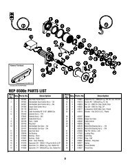
Patriot Profile 6000144035266381274934221521332439143172028372131 43 32 134130529**1926372881611 3423321225181016** See page 5 Installation for determinationof correct bolt.ItemNo.Qty. Part No. DescriptionPatriot Profile 6000 <strong>Winch</strong> Parts ListItemNo.Qty. Part No. Description1 1 247006 GEAR CARRIER ASSY - OUTPUT 22 1 414829 CAPSCREW 1/4-20NC X 1" SOC BUTTON HD2 1 247007 GEAR CARRIER ASSY - INTERMEDIATE 23 1 414830 CAPSCREW 1/4-20NC X 3/8 LG BUTT HD3 1 247024 GEAR CARRIER ASSY - INPUT 24 6 414861 CAPSCREW 1/4-20NC X 3/4 LG FLAT SOC HD NYLOK*4 1 251110 SWITCH ASSY 25 6 416273 SCREW #6-32NC X 3/8 LG FIL HD F/B5 1 251256 CABLE ASSY - 1/4 DIA. X 100' 26 1 418029 NUT 5/16-18NF HX JAM PLTD6 1 278189 SOLENOID ASSY - 12V 27 4 418035 NUT 3/8-16NC HX REG PLTD7 1 289141 CABLE ASSY - GROUND 28 5 418177 LOCKWASHER-3/8 ID MED SECT PLTD8 1 296553 BRAKE/SHAFT ASSY 29 4 418181 WASHER-FLAT 3/8 ID SAE PLTD9 1 296570 MOTOR-12V 30 1 442207 GASKET-COVER10 1 282062 ON/OFF SWITCH ASSEMBLY 31 1 444048 GEAR-OUTPUT SUN11 1 332128 DRUM-CABLE 32 1 444097 GEAR-INPUT SUN12 1 334143 GEAR-RING 33 2 448049 TIE BAR13 1 334147 GEAR-INTERMEDIATE SUN 34 1 448071 CABLE ANCHOR14 1 338337 END BEARING-GEAR HOUSING 35 1 452001 KNOB-SHIFTER15 1 408315 SOLENOID MOUNTING BRACKET 36 1 477002 LOCKING RING16 2 412056 BUSHING-DRUM 37 2 477004 RING-HALF17 1 412061 BUSHING-SHAFT 38 1 477011 CAM RING18 1 413018 COVER-GEAR HOUSING 39 1 479007 RETAINER-RING GEAR**19 4 414316 CAPSCREW 3/8-16NC X 1-1/4 LG HX HD GR5 PLTD 40 6 494077 SPRING2 414317 CAPSCREW 3/8-16NC X 1-3/4 LG HX HD GR5 PLTD 41 2 518019 THRUST WASHER20 1 414370 CAPSCREW 3/8-24NFX X 1/2 HX HD GR5 Z/P 42 1 518027 THRUST DISC21 4 414823 CAPSCREW 1/4-20NC X 3/4 LG SOC BUTT HD F/B 43 2 519020 THRUST WASHER11
Patriot Profile 8000144035266381274362291521342439242172028372131 42 31 134130529**1927372881611 3323324325181016** See page 5 Installation for determinationof correct bolt.ItemNo.Qty. Part No. DescriptionPatriot Profile 8000 <strong>Winch</strong> Parts ListItemNo.Qty. Part No. Description1 1 247005 GEAR CARRIER ASSY - INTERMEDIATE 22 1 414829 CAPSCREW 1/4-20NC X 1" SOC BUTTON HD2 1 247008 GEAR CARRIER ASSY - OUTPUT 23 1 414830 CAPSCREW 1/4-20NC X 3/8 LG BUTT HD3 1 247024 GEAR CARRIER ASSY - INPUT 24 6 414861 CAPSCREW 1/4-20NC X 3/4 LG FLAT SOC HD NYLOK4* 1 251110 SWITCH ASSY 25 6 416273 SCREW #6-32NC X 3/8 LG FIL HD F/B5 1 251255 CABLE ASSY - 5/16 DIA X 95' 26 1 418029 NUT 5/16-18NF HX JAM PLTD6 1 278189 SOLENOID ASSY - 12V 27 4 418035 NUT 3/8-16NC HX REG PLTD7 1 289141 CABLE ASSY - GROUND 28 5 418177 LOCKWASHER-3/8 ID MED SECT PLTD8 1 296553 BRAKE/SHAFT ASSY 29 4 418181 WASHER-FLAT 3/8 ID SAE PLTD9 1 296570 MOTOR-12V 30 1 442207 GASKET-COVER10 1 282062 ON/OFF SWITCH ASSEMBLY 31 1 444048 GEAR-OUTPUT SUN11 1 332128 DRUM-CABLE 32 1 444097 GEAR-INPUT SUN12 1 334143 GEAR-RING 33 1 448046 CABLE ANCHOR13 1 334145 GEAR-INTERMEDIATE SUN 34 2 448049 TIE BAR14 1 338337 END BEARING-GEAR HOUSING 35 1 452001 KNOB-SHIFTER15 1 408315 SOLENOID MOUNTING BRACKET 36 1 477002 LOCKING RING16 2 412056 BUSHING-DRUM 37 2 477004 RING-HALF17 1 412061 BUSHING-SHAFT 38 1 477011 CAM RING18 1 413018 COVER-GEAR HOUSING 39 1 479007 RETAINER-RING GEAR19** 4 414316 CAPSCREW 3/8-16NC X 1-1/4 LG HX HD GR5 PLTD 40 6 494077 SPRING2 414317 CAPSCREW 3/8-16NC X 1-3/4 LG HX HD GR5 PLTD 41 2 518019 THRUST WASHER20 1 414370 CAPSCREW 3/8-24NFX X 1/2 HX HD GR5 Z/P 42 1 518027 THRUST DISC21 4 414823 CAPSCREW 1/4-20NC X 3/4 LG SOC BUTT HD F/B 43 2 519020 THRUST WASHER12
Patriot Profile 950017423728640167493825 182433363441273432024154312330392134332531**2229393081912] 3526144421111910** See page 5 Installation for determinationof correct bolt.ItemNo.Qty. Part No. DescriptionPatriot Profile 9500 <strong>Winch</strong> Parts ListItemNo.Qty. Part No. Description1 1 247009 GEAR CARRIER ASSY - INPUT 22** 4 414316 CAPSCREW 3/8-16NC X 1-1/4 HX HD2 1 247022 GEAR CARRIER ASSY - INTERMEDIATE 2 414317 CAPSCREW 3/8-16NC X 1-3/4 HX HD3 1 247023 GEAR CARRIER ASSY - OUTPUT 23 1 414370 CAPSCREW 3/8-24NF X 1/2 HX HD4* 1 251110 SWITCH ASSY 24 4 414823 CAPSCREW 1/4-20NC X 3/4 SOC BT HD5 1 251257 CABLE ASSY - 5/16 DIA X 105' 25 1 414829 CAPSCREW 1/4-20NC X 1" SOC BUTTON HD6 1 278189 SOLENOID ASSY - 12V 26 1 414830 CAPSCREW 1/4-20NC X 3/8 BUTTON HD1 278188 SOLENOID ASSY - 24V 27 6 414861 CAPSCREW 1/4-20NC X 3/4 FL SOC HD NYLOK7 1 289141 CABLE ASSY - GROUND 28 1 418029 NUT 5/16-18NC HEX JAM PLTD8 1 296181 BRAKE/SHAFT ASSY 29 4 418035 NUT 3/8-16NC HEX REG PLTD9 1 296570 MOTOR-12V 30 5 418177 LOCKWASHER-3/8 ID MED SECT PLTD1 296591 MOTOR-24V 31 4 418181 WASHER-FLAT 3/8 ID SAE PLTD10 1 282062 ON/OFF SWITCH ASSY - 12V 32 1 442208 GASKET-COVER1 282063 ON/OFF SWITCH ASSY - 24V 33 1 442219 GASKET-RING GEAR11 1 328138 COVER-GEAR HOUSING 34 1 444077 GEAR-RING INPUT12 1 332193 DRUM-CABLE 35 1 448046 CABLE ANCHOR13 1 334147 GEAR-INTERMEDIATE SUN 36 2 448049 TIE BAR14 1 334154 GEAR-INPUT SUN 37 1 452001 KNOB SHIFTER15 1 334197 GEAR-OUTPUT SUN 38 1 477002 LOCKING RING16 1 334171 GEAR-RING, OUTPUT 39 2 477004 RING-HALF17 1 338337 END BEARING-GEAR HOUSING 40 1 477011 CAM RING18 1 408315 SOLENOID MOUNTING BRACKET 41 1 479007 RETAINER-RING GEAR19 2 412056 BUSHING-DRUM 42 6 494077 SPRING20 1 412061 BUSHING-SHAFT 43 6 518020 THRUST WASHER21 6 414159 CAPSCREW 5/16-18NC X 2-1/2 HX HD NYLOK 44 1 518027 THRUST DISC13
Solenoid Assembly Parts List278189 12V (Patriot Profile 6000, 8000, 9500)278188 24V (Patriot Profile 9500)ItemNo.Qty. Part No. DescriptionItemNo.Qty. Part No. Description1 1 204281 ASSEMBLY - SOLENOID BRACKET 9 4 416216 SCREW - #10-24NC X 1/2 LG2 1 289015 ASSEMBLY - WIRE BATTERY CABLE 72" LG 10 10 418014 NUT - HX 1/4-20NC REG Z/P3 2 289077 ASSEMBLY - WIRE #6 GA X 4.5" BLACK 11 8 418149 LOCKWASHER - 1/4 MED SECT Z/P4 3 289170 ASSEMBLY - WIRE #2 GA X 29" MTR LEAD 12 2 418514 SPACER - SOLENOID BRACKET5 1 296594 COVER ASSEMBLY 13 2 440260 STRAP - COPPER6 1 408271 BRACKET - SOLENOID MOUNTING 14 4 440262 SOLENOID - 12V7 6 414042 CAPSCREW 1/4-20NC X 5/8" HX HD 4 440265 SOLENOID - 24V8 2 414062 CAPSCREW 1/4-20NC X 1-1/2" GR5 Z/P 15 1 440281 ASSEMBLY - WIRE GROUND16 1 472069 GROMMETRoller Fairlead#251183Included with Patriot Profile 6000, 8000,and 9500 winches. Mounting hardware for rollerfairlead included with winch.14
Warranty Information<strong>Ramsey</strong> <strong>Winch</strong>es are designed and built to exacting specifications. Care and skill go into every winch we make. Ifthe need should arise, warranty procedure is outlined on the back of your self-addressed postage paid warrantycard. Please read and fill out the enclosed warranty card and send it to <strong>Ramsey</strong> <strong>Winch</strong> <strong>Company</strong>. If you have problemswith your winch, please follow instructions for proper service on all warranty claims.Limited Lifetime Warranty<strong>Ramsey</strong> <strong>Winch</strong> offers a limited lifetime warranty for each new<strong>Ramsey</strong> consumer/RV winch against manufacturing defects in workmanshipand materials on all mechanical components.Warranty registration cards for each winch must be submitted atthe time of purchase or within 30 days. Warranty will only be validfor the original purchase of the winch and installed on the vehicleswith which they were originally registered.New cable assemblies are warranted against defects in workmanshipand materials. No warranty applies after initial use.All <strong>Ramsey</strong> mounting kits and other accessories carry a 1-year limitedwarranty against defects in material and workmanship.This warranty is void if winch is used in commercial/industrial applicationsother than front mount self-recovery.Electrical components consisting of motors, solenoids, wiring, wireconnectors and associated parts carry a 1-year limited warranty.Battery isolators carry a 90-day limited warranty.The obligation under this Warranty, statutory or otherwise, is limitedto the replacement or repair at the manufacturer’s factory, or at apoint designated by the manufacturer, upon inspection of such part,to have been defective in material or workmanship. This Warrantydoes not obligate <strong>Ramsey</strong> <strong>Winch</strong> <strong>Company</strong> to bear the cost of transportationcharges in connection with the replacement or repair ofdefective parts, nor shall it apply to a product upon which repairs oralterations have been made, unless authorized by the manufacturer,or for equipment misused, neglected, or improperly installed.IMPORTANT NOTICE: To the fullest extent permitted by applicablelaw, the following are hereby excluded and disclaimed:1. All warranties of fitness for a particular purpose; 2. Allwarranties of merchantability; 3. All claims for consequentialor incidental damages. There are no warranties that extendbeyond the description that appears on the face hereof.Some states do not allow the above exclusions or disclaimersin consumer transactions and as such this disclaimer/exclusionmay not apply to your particular case.To the extent such warranties of fitness for a particular purpose ormerchantability are deemed to apply to this product, they exist foronly so long as the express limited warranty elsewhere set forth isin existence.<strong>Ramsey</strong> <strong>Winch</strong> <strong>Company</strong> makes no warranty in respect to accessories,same being subject to the warranties of their respectivemanufacturers.<strong>Ramsey</strong> <strong>Winch</strong> <strong>Company</strong>, whose policy is one of continuous productimprovement, reserves the right improve any product throughchanges in design and materials as it may deem desirable withoutbeing obligated to incorporate such changes in products of previousmanufacture.If field service at the request of the buyer is rendered and the fault isfound not to be with <strong>Ramsey</strong> <strong>Winch</strong> <strong>Company</strong>’s product, the buyershall pay the time and expense cost of the field representative. Billsfor service, labor, or other expenses which have been incurred bythe buyer without express approval or authorization by <strong>Ramsey</strong><strong>Winch</strong> <strong>Company</strong> wil not be accepted.This warranty gives you specific legal rights and you may also haveother legal rights which vary from state to state.15
FRENCH<strong>Ramsey</strong> <strong>Winch</strong> <strong>Company</strong>GUIDE DE L'UTILISATEURTreuils électriques avant12 et 24 VPATRIOT PROFILE 6000 PATRIOT PROFILE 8000Couche(s) de câble 1 2 3 4Capacité de tractionnominale par coucheCapacité de tractioncumulative par couche(1/4" - 6mm - dia.)(lbs) 6,000 5,000 4,400 3,800(kg) 2,720 2,260 1,990 1,720(ft)* 20 50 80 100(m)* 6 15 24 30Couche(s) de câble 1 2 3 4Capacité de traction (lbs) 8,000 6,500 5,500 4,800nominale par couche (kg) 3,620 2,940 2,490 2,170Capacité de traction (ft)* 15 40 70 95cumulative par couche(5/16" - 8mm - dia.) (m)* 4 12 21 28Capacité de traction,première coucheVitesse de traction,première coucheCourant tiré(lbs) 0 1,000 3,000 5,000 6,000(kg) 0 450 1,350 2,260 2,720(FPM)12V 45 23 20 14 1224V 46 24 19 15 12(MPM)12V 13.7 7 6.1 4.3 3.724V 14 7.3 5.8 4.6 3.712V 100 200 270 350 40524V 43 90 128 170 190* À condition que le câble soit uniformément distribué sur l'enrouleurFélicitations!Vous venez de vous procurer le meilleur treuil dans sa catégorie! Il présenteun train planétaire à trois étages extrêmement efficace qui transmet son couplepar l'entremise d'un moteur à courant continu (c.c.) à enroulement série. Sonembrayage direct sécuritaire permet le décrabotage, ce qui accélère ledéploiement du câble. Il est en outre équipé d'un frein à correction automatiquede charge conçu pour supporter la pleine capacité nominale du treuil.Ces treuils ont été dessinés et fabriqués de manière à être le plus utiles possible.Mais comme tous les dispositifs qui allient puissance et mouvement, ilsprésentent certains dangers si on ne les utilise pas correctement. En prenantd'abord toutes les précautions requises, on élimine non seulement ces dangers,mais on facilite et on accélère les tâches à effectuer.Capacité de traction,première coucheVitesse de traction,première coucheCourant tiréPATRIOT PROFILE 9500Couche(s) de câble 1 2 3 4 5Capacité de traction (lbs) 9,500 7,700 6,500 5,700 4,900nominale par couche (kg) 4,309 3,480 2,940 2,580 2,210Capacité de traction (ft)* 15 35 60 90 105cumulative par couche(5/16" - 8mm - dia.) (m)* 4 10 18 27 32Capacité de traction,première coucheVitesse de traction,première coucheCourant tiré(lbs) 0 2,000 4,000 6,000 8,000(kg) 0 900 1,810 2,720 3,620(FPM)12V 35 18 13 10 824V 30 17 13 10 8(MPM)12V 10.7 5.5 4 3 2.424V 9.1 5.2 4 3 2.412V 95 210 270 355 42024V 43 93 125 160 200(lbs) 0 2,000 4,000 6,000 8,000 9,500(kg) 0 900 1,810 2,720 3,620 4,309(FPM)12V 35.4 16.7 12.7 10.6 9 7.824V 29 16 13 10 9 8(MPM)12V 10.7 5.1 3.8 3.2 2.7 2.324V 8.8 4.9 4.0 3.0 2.7 2.412V 97 180 260 335 395 43024V 45 95 128 165 192 212Veuillez donc prendre la peine de lire le présent guide attentivement; il contient des renseignementsutiles pour tirer le meilleur parti de votre treuil <strong>Ramsey</strong>, de même que des consignesde sécurité qu'il vous faut savoir avant de l'utiliser pour la première fois. En observant notremode d'emploi, vous garantirez que votre treuil vous offre des années de satisfaction. Nousvous remercions d'avoir choisi <strong>Ramsey</strong>; nous sommes convaincus que vous ne le regretterezpas!Remarque : les treuils Patriot MC de <strong>Ramsey</strong> sont conçus pour être fixés à l'avant d'unvéhicule. Ils ne conviennent pas aux applications commerciales ou industrielles(remorqueuses, porte-voitures, dépanneuses, opérations de levage, etc.) et <strong>Ramsey</strong>n'en garantit pas le fonctionnement dans de telles conditions; la société offre desgammes complètes et distinctes de treuils réservés à ces usages. Prière de communiqueravec l'usine pour obtenir de plus amples renseignements à ce sujet.MISE EN GARDE : on doit lire et comprendre le présent guide avant de procéder à l'installation et à l'utilisation du treuil. Sereporter à la section Consignes de sécurité.17
Table des matièresCaractéristiques techniques . . . . . . . . . . . . . . . . . . . . . . . . . . . . . . . . . . . . . . . . . .17Consignes de sécurité . . . . . . . . . . . . . . . . . . . . . . . . . . . . . . . . . . . . . . . . . . . . . .19Conseils de sécurité . . . . . . . . . . . . . . . . . . . . . . . . . . . . . . . . . . . . . . . . . . . . . . . .19Trucs et techniques . . . . . . . . . . . . . . . . . . . . . . . . . . . . . . . . . . . . . . . . . . . . . . . .20Installation . . . . . . . . . . . . . . . . . . . . . . . . . . . . . . . . . . . . . . . . . . . . . . . . . . . . .21-24Mode d'emploi . . . . . . . . . . . . . . . . . . . . . . . . . . . . . . . . . . . . . . . . . . . . . . . . . . . .25Fonctionnement et câblage électrique . . . . . . . . . . . . . . . . . . . . . . . . . . . . . . . . . . .25Lubrification/Installation du câble . . . . . . . . . . . . . . . . . . . . . . . . . . . . . . . . . . . . . .25Diagnostic des anomalies . . . . . . . . . . . . . . . . . . . . . . . . . . . . . . . . . . . . . . . . . . . .26Liste des pièces . . . . . . . . . . . . . . . . . . . . . . . . . . . . . . . . . . . . . . . . . . . . . . . .27-30Garantie . . . . . . . . . . . . . . . . . . . . . . . . . . . . . . . . . . . . . . . . . . . . . . . . . . . . . . . . .3118
Consignes de sécuritéLe câble doit faire au moins cinq tours sur l'enrouleurpour pouvoir soutenir la charge nominale du treuil, ceque le serre-câble est incapable de faire.A. L'utilisateur ainsi que toute autre personne doivent se tenir à unedistance latérale sécuritaire du câble lorsque celui-ci tire unecharge.B. On ne doit pas tenter d'enjamber le câble ou de marcher près dece dernier quand il tire une charge.C. On doit se servir de la sangle fournie lorsqu'on manipule le crochet(cable hook) pour enrouler un câble métallique.D. On ne doit pas déplacer le véhicule pour tirer sur une longue distanceune charge accrochée au câble, ce qui pourrait causer lebris de ce dernier ou l'endommagement du treuil.E. On doit avoir recours à des gants ou à un chiffon épais pour seprotéger des barbures quand on manipule le câble.F. On doit bloquer les roues du véhicule quand celui-ci est sur unepente.G. L'embrayage du treuil doit être désaccouplé quand ce derniern'est pas utilisé, et complètement accouplé quand il l'est.H. Les modifications, changements ou déviations apportés à cestreuils doivent être confiés à la <strong>Ramsey</strong> <strong>Winch</strong> <strong>Company</strong>.I. On doit réduire au minimum la durée de chaque traction. Si lemoteur devient inconfortablement chaud au toucher, on doit l'arrêteret le laisser refroidir pendant quelques minutes. Lescharges nominales ou presque nominales ne doivent pas êtretirées plus de une minute. Couper l'alimentation du treuil si lemoteur cale. Ces treuils électriques sont conçus pour un usageintermittent et ne doivent pas être utilisés en applications deservice constant.J. On doit déconnecter la télécommande du treuil quand celui-cin'est pas utilisé.K. Remarque : on ne doit pas se servir de ces treuils en applicationsde levage puisqu'ils ne répondent pas aux exigences deces dernières en matière de caractéristiques et de sécurité.L. On ne doit pas dépasser les capacités de traction nominalesapparaissant aux tableaux du présent guide; les surcharges d'impactdoivent rester en dessous des valeurs qui y sont indiquées.M. Pour réenrouler correctement le câble, il est nécessaire de luiappliquer une certaine charge. Pour ce faire, on doit tenir lecâble d'une main (gantée) et la télécommande de l'autre, encommençant le plus loin et le plus au centre possible et enmarchant vers le véhicule en maintenant la tension sur le câblependant que le treuil fait son travail. Prendre soin de ne paslaisser glisser le câble de sa main et ne pas trop s'approcher dutreuil. Arrêter ce dernier et reprendre la procédure jusqu'à ce qu'ilne reste plus qu'environ un mètre de câble à réenrouler.Déconnecter la télécommande et terminer la procédure enfaisant tourner l'enrouleur manuellement (embrayage désaccouplé).En présence de treuils cachés, réenrouler le câblemécaniquement, en utilisant la sangle de crochet fournie.Conseils de sécuritéIl ne faut jamais sous-estimer les risques potentiels associés à l'utilisationd'un treuil, mais il ne faut pas non plus les craindre outremesure. Il s'agit de connaître les dangers principaux et de tout fairepour les éviter.Il faut notamment examiner la disposition du câble sur l'enrouleur; sion tire latéralement, il peut en effet s'accumuler d'un côté. Pourremédier à ce problème, on doit dérouler la section empilée, ladéplacer vers l'autre extrémité de l'enrouleur, puis procéder au treuillage.Si l'enroulement n'est pas uniforme, le câble accumulé pourraitnuire au carter du solénoïde, ce qui entraînerait l'endommagementdu treuil.On recommande de ranger la télécommande à l'intérieur du véhiculeafin de la protéger d'éventuels dommages, et de l'inspecter avec dela brancher.Lorsqu'on est prêt à procéder à l'enroulement, on doit débrayer pourbrancher la télécommande; l'embrayage ne doit jamais être accouplépendant que le moteur est en marche.On ne doit jamais amarrer le crochet au câble, ce qui pourraitendommager ce dernier. Il faut plutôt employer une bretelle ou unechaîne assez forte, tel qu'illustré.Dans la mesure du possible, on doit garder l'œil sur le treuil pendantqu'il fonctionne (tout en se tenant à une distance respectable). Si onutilise la force motrice du véhicule pour aider à tirer, il faut sortir àchaque mètre parcouru pour s'assurer que le câble ne s'accumulepas d'un côté de l'enrouleur. Un blocage de câble peut provoquer lebris du treuil.Ne pas fixer de crochet de remorquage aux dispositifs de fixation dutreuil (le crochet doit plutôt être assujetti au châssis du véhicule).Lorsqu'on utilise deux câbles en situation de treuillage stationnaire,le crochet devrait également être assujetti au châssis du véhicule.Étant donné que c'est la couche la plus près de l'enrouleur qui produitla plus grande force de traction, il est préférable de sortir autantde câble que possible lorsqu'on veux tirer une charge plus lourde.S'il est impossible de procéder ainsi, on peut utiliser une mouflemobile et deux câbles (voir illustration). Il importe de se rappeler quele câble doit faire au moins cinq tours sur l'enrouleur pour pouvoirtirer sa charge nominale.En enroulant le câble de manière uniforme et serrée, on évite lesblocages engendrés par les coincements entre deux câbles. Si celase produit, il suffit de faire avancer et reculer le treuil de quelquespouces à la fois. Il ne faut jamais tenter de dégager mécaniquementun câble bloqué lorsqu'il est chargé; le cas échéant, procédermanuellement.19
Trucs et techniquesLa meilleure façon de connaître le fonctionnement d'un treuilest de procéder à quelques essais avant d'en avoir réellementbesoin. Ces essais doivent être planifiés à l'avance. Avec letemps, on arrive à distinguer le son d'une traction légère etuniforme de celui d'un effort soutenu ou d'une procédureirrégulière où la charge avance par à-coups ou se déplacelatéralement. On prend ainsi toute l'assurance requise pourutiliser le treuil presque d'instinct.Un treuil peut non seulement tirer un véhicule en haut d'unepente ou l'aider à la descendre, mais aussi permettre d'enremorquer un autre ou encore une charge si le véhicule estancré en position stationnaire. Les scénarios suivants illustrentcertaines techniques à adopter.Lorsqu'on veut tirer une charge importante, il faut mettre unecouverture, un manteau ou une bâche sur le câble sur lesdeux premiers mètres à partir du crochet et ce, afin de ralentird'éventuels retours si le câble se brise. Il faut également ouvrirle capot du véhicule pour plus de protection.On peut se servir d'une force motrice pour assister le treuil,mais il faut s'assurer que le câble ne passe pas sous levéhicule. La procédure doit être bien planifiée. On peutaccrocher la charge et la tirer en une seule opération. Pour cefaire, il faut bien examiner les points d'ancrage possibles, demême que les situations, les directions et les objectifs detraction.Pour tirer un véhicule d'une simple mauvaise posture,ancrer le câble à un arbre (se servir alors d'un protecteurde tronc) ou à une pierre lourde.Les treuils munis de fils guide-câble peuvent tirer descharges de plusieurs directions. On ne doit cependanttirer en angle que pour rétablir le véhicule, au risqued'endommager les éléments structurels ou d'autrespièces de ce dernier ou encore d'engendrer une accumulationde câble d'un côté de l'enrouleur.Une série de piquets plantés dans un sol compact etreliés par une chaîne peut constituer un bon point d'ancrageen cas d'autorétablissement simple, quand lecâble ne peut être fixé à aucun élément naturel.Pour tirer directement une charge pouvant aller jusqu'à900 kg, accrocher le véhicule à un point d'ancragesolide (un arbre, par exemple) et le mettre au neutre.Pour obtenir un point d'ancrage solide, enterrer partiellementun billot dans de la terre ou du sable, ou le mettredans un fossé profond.20Pour doubler la force de traction, on peut se servir dedeux câbles, avec une moufle mobile et une attache auchâssis (le véhicule doit être mis au neutre).
InstallationLes treuils décrits dans le présent guide sont exclusivement conçuspour une installation à l'avant d'un véhicule et pour des applicationsnon industrielles ou commerciales. Tout autre emploi en annulerait lagarantie.Remarque : en présence d'un protège-calandre, la manette d'embrayage(clutch shifter knob) pourrait devoir être déplacée. Sereporter alors aux pages 7 et 8 pour savoir comment procéder.Il est très important de fixer le treuil à une surface plane, de manièreà ce que ses trois sections principales (le moteur, l'enrouleur et l'engrenage)soient bien alignées. On recommande d'utiliser une trousse<strong>Ramsey</strong> pour procéder à l'installation; ces trousses sont conçuespour aligner le treuil, en distribuant la charge nominale uniformément,ce qui permet d'éviter d'éventuels dommages au treuil et auvéhicule.Remarque : si on n'utilise pas la trousse <strong>Ramsey</strong>, on doit se servird'une autre de conception équivalente.Pour fixer son treuil Patriot Profile 6000, 8000, ou 9500, on peutégalement se procurer une des goulottes (mounting channel) suivantes:• 251126, courte, 60,02 cm, noire• 251127, moyenne, 76,20 cm, noire• 251128, longue, 91,44 cm, noireOn recommande d'utiliser une goulotte pour toutes les installationsutilisant des dispositifs autres que ceux de <strong>Ramsey</strong>.Pour fixer le treuil dans une goulotte régulière (comme cellesoffertes par <strong>Ramsey</strong>), on doit utiliser quatre boulons de fixation(winch mounting bolt) de 3 cm, tel qu'illustré ci-dessous.* En présence d'un protège-calandre, il pourrait être nécessairede remplacer les deux boulons de 44,5 mm fournis par desplus courts (31,8 mm). Se reporter au DÉTAIL A ci-dessous : sil’épaisseur de la surface de montage (DIM A) est de 6,4 mm oumoins, il faut employer des boulons de 31,8 mm; si la surfaceest plus épaisse, il est préférable de garder les boulons de 44,5mm. (Si l’épaisseur se situe entre 6,4 et 14,2 mm, on peutajouter des rondelles pour empêcher l'extrémité des boulons detoucher les supports du treuil, tel qu'illustré au DÉTAIL B.)Il ne faut cependant utiliser des boulons plus longs qu'encas de nécessité, puisqu’ils risquent d’endommager le treuil.Une fois les boulons serrés, s’assurer qu’il y ait suffisammentd’espace libre (DÉTAIL B) au-dessus de leur extrémité. (Une partiedu filetage doit rester visible au-dessus de l’écrou.).** Lorsqu’on installe le treuil sur un protège-calandre, leguide-câble à rouleaux pourrait devoir être tourné de 180° pouren assurer l'alignement avec l'enrouleur.*Manette decommandeDÉTAIL AEspaceinsuffisantGoulotteGuide-câbleà rouleauxBoulon de fixation duguide-câble3/8-16NC X 1-1/4” LG.DÉTAIL B** Pour garantir l’alignement duguide-câble avec l’enrouleur, se servirdes plus petits trous pour le montage.Diamètrede 12,7 mmDiamètre de11,1 mmBoulon de fixation du treuil3/8-16NC X 1-1/4” LG.21
Fixer le guide-câble à la goulotte au moyen des ferruresfournies. Installer le treuil dans la goulotte. Insérer des vis defixation dotées de rondelles de blocage dans les orifices defixation de la goulotte, puis à travers les supports du treuil (sereporter à la figure de la page précédente).En remplaçant les ferrures fournies (boulons, écrous ou rondelles)par des accessoires différents, on s'expose à desrisques de défaillance susceptibles d'engendrer des dommagesou des blessures graves (le cas échéant, employer deséléments homologués SAE n° 5 ou plus, et exercer un couplede serrage de 34 pi-lb).Passer l'extrémité du câble métallique à travers le guide-câbleet fixer le crochet, en se servant d'un axe à épaulement etd'une goupille fendue.Pour installer le solénoïde (solenoid assembly), on doit seservir du support de montage fourni. Fixer ce dernier à labarre d'attache au moyen de une vis 1/4-20NC de 2,5 cm aulieu de celle de 2,0 cm. Assujettir le support à l'arrière dusolénoïde au moyen des écrous et des rondelles de blocagefournis.Lorsqu'on fixe le treuil, il faut raccorder les fils de sortie identifiés(motor leads) du solénoïde aux bornes appropriées dumoteur, tel qu'illustré à droite. Serrer les écrous de cesbornes fermement. Relier le fil de terre du solénoïde (groundwire) au boulon de terre situé sur la partie inférieure dumoteur (le fil de terre de l'accumulateur [battery ground wire]y est déjà raccordé).AAA12View Vue A-A22
Repositionnement de la manette d'embrayage en présence d'un protège-calandreRemarque : la manette d'embrayage est correctement placée pour la plupart des applications, mais elle pourraitdevoir être déplacée en présence de certains protège-calandre.Se reporter à la liste des pièces (Parts List) et à la vue éclatée (Exploded Parts Diagram) relatives au modèle de treuilutilisé, apparaissant ailleurs dans le présent guide.1. Placer le treuil de la manière illustrée à la figure 1. Retirer les vis des barres d'attache (à l'extrémité moteur, onpeut peut-être simplement les dévisser sans les retirer). Séparer le logement de l'engrenage de l'enrouleur et dumandrin et le déposer sur l'établi en mettant le couvercle vers le haut. Retirer la bague de l'enrouleur du logementde l'engrenage ou del'extrémité de l'enrouleur;la mettre decôté.2. Retirer les six vis defixation du couvercle dulogement de l'engrenage.En tenant cecouvercle au-dessus dulogement, le retourneret le déposer surFigure 1l'établi.3. Soulever délicatement le logement del'engrenage en manipulant les élémentsinternes (roues, bagues, etc.) demanière à ce qu'ils s'empilent sur l'établi(figure 2).4. Retourner le logement de l'engrenage etle déposer sur l'établi. Retirer le dispositifde retenue (article 37 - retainer) enenlevant les six vis de fixation (article 21- capscrews) du palier de l'extrémitéengrenage (article 13 - gear end bearing).Une fois cette étape complétée, lacouronne (article 10 - ring gear), lacouronne à cames (article 36 - camring) et la rondelle de blocage (article 34- locking ring) peuvent être soulevées dupalier.Retirer les six ressorts (article 38 -springs) du palier.Figure 323Figure 2
5. Déterminer la position dans laquelle la manettedoit être. Remarque: elle ne peut être placée tropbas puisqu'elle serait ainsi gênée par le supportdu palier de l'extrémité engrenage (possibilités deplacement [Range of position] à la figure 4).6. Pour placer la manette au bon endroit, mettre larondelle de blocage du palier d'extrémité (endbearing) et sa butée (stop post) à un angle d'environ180° de l'emplacement visé. Poser lacouronne à cames en position au-dessus de larondelle de blocage et s'assurer que la manettepuisse se déplacer librement. Marquer la positionde la butée sur le palier d'extrémité.Figure 47. Enlever la couronne à cames et la rondelle de blocage du palier. Insérer les ressorts (article 38) dans ce dernier.Au moment de remettre la rondelle de blocage (article 34) sur les ressorts, s'assurer que ceux-ci se comprimentbien dans leurs alvéoles, sans plier latéralement.8. Remonter le logement de l'engrenage tel qu'illustré à la figure 3. S'assurer que la rondelle de blocage soit placéede manière à ce que la butée arrive à l'endroit marqué. Les vis de fixation (article 21) du dispositif de retenuedevraient être serrées en appliquant un couple de 40 à 45 po-lb. Ne pas trop serrer.9. Remettre le logement de l'engrenage sur les éléments empilés et retirés à l'étape 3. Manipuler délicatement lelogement en le tournant au besoin pour qu'à l'intérieur, les roues du train planétaire entrent en prise avec lacouronne. Un fois le tout inséré, retourner l'assemblage et aligner le couvercle et le joint d'étanchéité avec lestrous de la couronne. Remettre les six vis de fixation du couvercle pour le fixer au logement. Serrer fermement.10. Mettre la manette en position de dégagement.11. Retourner le logement de l'engrenage et le déposersur l'établi, en mettant le couvercle vers le bas (figure5).12. Installer la bague de l'enrouleur sur le logement, enconfirmant que la fente de la bague s'aligne avec laclavette du palier d'extrémité. Prendre le reste dutreuil (enrouleur et moteur) et, en tenant l'enrouleur,abaisser le treuil sur l'extrémité engrenage. Enfoncerle mandrin dans l'extrémité engrenage; il pourraits'avérer nécessaire de tourner légèrement l'enrouleurpour permettre au mandrin d'entrer jusqu'au bout.13. Poser les barres d'attache sur les extrémités moteuret engrenage; fixer le tout au moyen de quatre vis.Serrer fermement.14. Une fois le treuil remonté, le retourner et le poser surFigure 5ses supports. Confirmer que le câble puissedécraboter quand la manette est en position de dégagement. Brancher temporairement le treuil et s'assurer que lecâble s'enroule quand la manette est en position de traction.24
Mode d'emploiL'embrayage du treuil permet le déroulement rapide d'un câblemétallique pour l'accrocher à une charge ou à un point d'ancrage.La manette d'embrayage est située du côté engrenagedu treuil et fonctionne comme suit :1. Pour débrayer, mettre la manette à la position de déroulement(OUT); le câble peut alors être facilement décraboté.2. Pour embrayer, mettre la manette à la position d'enroulement(IN); le treuil est alors prêt à tirer.Fonctionnement et câblage électriqueSe reporter aux directives d’installation de l’interrupteur desécurité (n° 282063, fourni avec le treuil).Pour les travaux d'autorétablissement normaux, le systèmeélectrique existant suffit. L'accumulateur du véhicule doitcependant être maintenu en bon état. Il est en effet essentielqu'il soit pleinement chargé et que les raccords soient bieneffectués. On doit faire tourner le moteur du véhicule quand onse sert du treuil afin de conserver la charge de l'accumulateur.Acheminer les fils d'accumulateur jusqu'à ce dernier.MISE EN GARDE : S'ASSURER QUE CES FILS NE SOIENT PASTENDUS SUR DES SURFACES SUSCEPTIBLES DE LESENDOMMAGER.Raccorder le fil rouge à la cosse positive (« + ») et le fil deterre noir à la cosse négative (« - »); se reporter à la figure 1.Étanche, la télécommande est dotée d'un bouton-poussoir dechaque côté. Il faut toujours s'assurer que le moteur soit complètementarrêté avant de passer en marche avant ou arrière.Pour activer le treuil, il suffit de brancher la télécommandedans la prise située sur le logement. Faire avancer et reculer lecâble pour confirmer que les raccords ont été bien effectuéset pour déterminer le sens de chaque bouton. Insérer les rondellesd'enroulement (IN) et de déroulement (OUT) dans lesrepose-pouce appropriés. Débrancher la télécommandequand le treuil n'est pas utilisé.MaintenanceToutes les pièces mobiles du treuil ont été lubrifiées en usineau moyen de graisse au lithium thermorésistante qui devrait,en conditions normales d'utilisation, tenir le coup pendanttoute la durée utile de l'appareil.La câble doit cependant être lubrifié périodiquement avec del'huile fluide dégrippante. On doit en outre l'inspecter pour ydéceler les brins brisés et le remplacer au besoin par l'articlecorrespondant de la liste de pièces du treuil utilisé. Si le câbleest usé ou endommagé, il doit être remplacé.La corrosion sur les raccords électriques peut réduire le rendementdu treuil ou causer un court-circuit. On doit doncnettoyer tous ces raccords, surtout au niveau de la télécommandeet de la prise. Pour plus de protection en milieu salin,on doit en outre utiliser un agent d'étanchéité à base de silicone.Pour réduire au minimum la corrosion engendrée par la condensationsur les composantes internes du moteur, onrecommande de mettre le treuil en marche périodiquement. Enfonctionnant, le moteur émettra de la chaleur qui aidera à dissipertoute accumulation d'humidité à l'intérieur. On devraitprocéder ainsi par intervalles réguliers, comme à chaquevidange d'huile du véhicule, par exemple. Remarque : sereporter à la section Diagnostic des anomalies si le moteur aété submergé.Installation du câble1. Pour empêcher le bouclage, étendre le câble neuf en ledéroulant sur le sol.2. Retirer le vieux câble et noter comment il est attaché aurebord de l'enrouleur.3. Avant d'installer le nouveau câble, s'assurer que sonextrémité soit coupée bien droite et enveloppée de rubande plastique ou autre pour l'empêcher de s'effilocher.4. Placer l'enrouleur de manière à ce que le grand trou(diamètre d'environ 10 mm) du rebord de l'enrouleur, côtémoteur, soit à peu près sur le dessus.5. Former un petit coude (long d'un peu plus de 1 cm) aubout du câble. Insérer ce coude dans ce trou et faire délicatementtourner le treuil dans le sens de l'enroulement(IN) sur environ 3/4 de tour, jusqu'à ce que le petit troufileté (d'environ 5 mm) soit à son tour sur le dessus.6. Fixer le câble au rebord de l'enrouleur au moyen du dispositifd'ancrage et de la vis de fixation illustrés dans ledessin des pièces de la page 11 (articles 20 et 30). Visserfermement, sans trop serrer.7. Enrouler manuellement le câble cinq fois autour de l'enrouleur.Procéder ensuite mécaniquement à l'enroulement,en mettant une légère charge au bout du câble pour maintenirune tension constante. S'assurer que le câble puissepivoter librement en utilisant une chaîne ou une moufleentre le crochet et la charge.25
Diagnostic des anomaliesÉtat Cause(s) possible(s) Correctif(s)LE MOTEUR NEFONCTIONNE QUE DANSUN SENSLE MOTEUR SURCHAUFFEBEAUCOUPLE MOTEUR FONCTIONNE,MAIS À RÉGIME OU ÀVITESSE DE TRACTIONTROP FAIBLESolénoïde coincé oudéfectueuxTélécommande défectueuseTrop long fonctionnementL’accumulateur est faibleMauvais raccordsSystème de chargementinsuffisantSecouer le solénoïde pour dégager les contacts. Vérifier sila borne de la bobine émet un déclic quand on y appliqueune tension de 12 V.Débrayer le treuil, débrancher la télécommande et relier lesbroches à 8 et à 4 heures. Le moteur devrait fonctionner.Relier les broches à 8 et à 10 heures. Le moteur devraitfonctionner.Faire des arrêts essentiels au refroidissement du moteur.Vérifier la tension aux cosses lorsque le treuil tire sa chargesi elle est de 10 V ou moins, remplacer l’accumulateur ouen brancher un second en parallèleS’assurer de l’absence de corrosion sur les fils del’accumulateur; le cas échéant, les nettoyer et les lubrifier.Le remplacer par un système plus puissant.LE MOTEUR FONCTIONNE,MAIS L’ENROULEUR NETOURNE PASLE MOTEUR NEFONCTIONNE PASLe treuil n'est pas embrayéSolénoïde coincé oudéfectueuxTélécommande défectueuseMoteur défectueuxRaccords desserrésSi la manette d’embrayage est en position d’enroulement eles symptômes persistent, il pourrait s’avérer nécessaire ddémonter le treuil pour trouver le problème et le régler.Secouer le solénoïde pour dégager les contacts. Vérifier sila borne de la bobine émet un déclic quand on y appliqueune tension de 12 V.Débrayer le treuil, débrancher la télécommande et relier lesbroches à 8 et à 4 heures. Le moteur devrait fonctionner.Relier les broches à 8 et à 10 heures. Le moteur devraitfonctionner.Si le solénoïde fonctionne, vérifier la tension à l’arbred’induit; remplacer le moteur si elle est inexistante.Serrer les raccords sous le carter et sur le moteur.26
Patriot Profile 6000144035266381274202893422152133372124391431731 43 32 134130529**1926372881611 3423321225181016** Se reporter aux directives de la page 5pour savoir quels boulons utiliser.N° deréférence Quantité N° depièceDescriptionListe des pièces du treuil Patriot Profile 6000N° deréférence Quantité N° depièceDescription1 1 247006 SUPPORT D’ENGRENAGE – SORTIE 22 1 414829 VIS DE FIXATION 1/4-20NC de 25,4 mm, tête creuse2 1 247007 SUPPORT D’ENGRENAGE – INTERMÉDIAIRE 23 1 414830 VIS DE FIXATION 1/4-20NC de 9,5 mm, tête ronde3 1 247024 SUPPORT D’ENGRENAGE – ENTRÉE 24 6 414861 VIS DE FIXATION 1/4-20NC de 19,1 mm, tête creuse plate,NYLOK4 1 251110 TÉLÉCOMMANDE 25 6 416273 VIS 6-32NC de 9,5 mm, tête hexagonale creuse, galvanisée5 1 251256 CÂBLE – 6,4 mm SUR 30,5 m 26 1 418029 ÉCROU 5/16-18NF, hexagonal bas, galvanisé6 1 278189 SOLÉNOÏDE (12 V) 27 4 418035 ÉCROU 3/8-16NC, hexagonal régulier, galvanisé7 1 289141 FIL DE TERRE 28 5 418177 RONDELLE DE BLOCAGE 3/8, sect. milieu, galvanisée8 1 296553 FREIN/MANDRIN 29 4 418181 RONDELLE PLATE 3/8, SAE, galvanisée9 1 296570 MOTEUR (12 V) 30 1 442207 JOINT – COUVERCLE10 1 282062 INTERRUPTEUR 31 1 444048 ENGRENAGE – ROUE SOLAIRE DE SORTIE11 1 332128 ENROULEUR 32 1 444097 ENGRENAGE – ROUE SOLAIRE D’ENTRÉE12 1 334143 ENGRENAGE – COURONNE 33 2 448049 BARRE D’ANCRAGE13 1 334147 ENGRENAGE – ROUE SOLAIRE INTERMÉDIAIRE 34 1 448071 ANCRAGE DU CÂBLE14 1 338337 PALIER D’EXTRÉMITÉ – CÔTÉ ENGRENAGE 35 1 452001 MANETTE DE COMMANDE15 1 408315 SUPPORT DE SOLÉNOÏDE 36 1 477002 RONDELLE DE BLOCAGE16 2 412056 BAGUE – ENROULEUR 37 2 477004 MOITIÉ DE BAGUE17 1 412061 BAGUE – MANDRIN 38 1 477011 ANNEAU DE CAME18 1 413018 COUVERCLE DU LOGEMENT DE L’ENGRENAGE 39 1 479007 DISPOSITIF DE RETENUE – COURONNE**19 4 414316 VIS DE FIXATION 3/8-16NC de 31,8 mm, tête hexagonale, 40 6 494077 RESSORTgalvanisée, classe 52 414317 VIS DE FIXATION 3/8-16NC de 44,5 mm, tête hexagonale, 41 2 518019 RONDELLE DE BUTÉEgalvanisée, classe 520 1 414370 VIS DE FIXATION 3/8-24NF de 12,7 mm, tête hexagonale, 42 1 518027 DISQUE DE BUTÉEgalvanisée, classe 521 4 414823 VIS DE FIXATION 1/4-20NC de 19,1 mm, tête creuse, noire 43 2 519020 RONDELLE DE BUTÉE27
Patriot Profile 8000144035266381274202836229152134372124392421731 42 31 134130529**1927372881611 3323324325181016** Se reporter aux directives de la page 5pour savoir quels boulons utiliser.N° deréférence Quantité N° depièceDescriptionListe des pièces du treuil Patriot Profile 8000N° deréférence Quantité N° depièceDescription1 1 247005 SUPPORT D’ENGRENAGE – INTERMÉDIAIRE 22 1 414829 VIS DE FIXATION 1/4-20NC de 25,4 mm, tête creuse2 1 247008 SUPPORT D’ENGRENAGE – SORTIE 23 1 414830 VIS DE FIXATION 1/4-20NC de 9,5 mm, tête ronde3 1 247024 SUPPORT D’ENGRENAGE – ENTRÉE 24 6 414861 VIS DE FIXATION 1/4-20NC de 19,1 mm, tête creuse plate,NYLOK4 1 251110 TÉLÉCOMMANDE 25 6 416273 VIS 6-32NC de 9,5 mm, tête hexagonale creuse, galvanisée5 1 251255 CÂBLE – 7,9 mm SUR 29,0 m 26 1 418029 ÉCROU 5/16-18NF, hexagonal bas, galvanisé6 1 278189 SOLÉNOÏDE (12 V) 27 4 418035 ÉCROU 3/8-16NC, hexagonal régulier, galvanisé7 1 289141 FIL DE TERRE 28 5 418177 RONDELLE DE BLOCAGE 3/8, sect. milieu, galvanisée8 1 296553 FREIN/MANDRIN 29 4 418181 RONDELLE PLATE 3/8, SAE, galvanisée9 1 296570 MOTEUR (12 V) 30 1 442207 JOINT – COUVERCLE10 1 282062 INTERRUPTEUR 31 1 444048 ENGRENAGE – ROUE SOLAIRE DE SORTIE11 1 332128 ENROULEUR 32 1 444097 ENGRENAGE – ROUE SOLAIRE D’ENTRÉE12 1 334143 ENGRENAGE – COURONNE 33 1 448046 ANCRAGE DU CÂBLE13 1 334145 ENGRENAGE – ROUE SOLAIRE INTERMÉDIAIRE 34 2 448049 BARRE D’ANCRAGE14 1 338337 PALIER D’EXTRÉMITÉ – CÔTÉ ENGRENAGE 35 1 452001 MANETTE DE COMMANDE15 1 408315 SUPPORT DE SOLÉNOÏDE 36 1 477002 RONDELLE DE BLOCAGE16 2 412056 BAGUE – ENROULEUR 37 2 477004 MOITIÉ DE BAGUE17 1 412061 BAGUE – MANDRIN 38 1 477011 ANNEAU DE CAME18 1 413018 COUVERCLE DU LOGEMENT DE L’ENGRENAGE 39 1 479007 DISPOSITIF DE RETENUE – COURONNE19** 4 414316 VIS DE FIXATION 3/8-16NC de 31,8 mm, tête hexagonale, 40 6 494077 RESSORTgalvanisée, classe 52 414317 VIS DE FIXATION 3/8-16NC de 44,5 mm, tête hexagonale, 41 2 518019 RONDELLE DE BUTÉEgalvanisée, classe 520 1 414370 VIS DE FIXATION 3/8-24NF de 12,7 mm, tête hexagonale, 42 1 518027 DISQUE DE BUTÉEgalvanisée, classe 521 4 414823 VIS DE FIXATION 1/4-20NC de 19,1 mm, tête creuse, noire 43 2 519020 RONDELLE DE BUTÉE28
Patriot Profile 9500174237286401674233093825 18243336393441272431543220134314332531**2229393081912] 3526144421111019** Se reporter aux directives de la page 5pour savoir quels boulons utiliser.N° deréférence Quantité N° depièceDescriptionListe des pièces du treuil Patriot Profile 9500N° deréférence Quantité N° depièceDescription1 1 247009 SUPPORT D’ENGRENAGE – ENTRÉE 22** 4 414316 VIS DE FIXATION 3/8-16NC de 31,8 mm, tête hexagonale,galvanisée, classe 52 1 247022 SUPPORT D’ENGRENAGE – INTERMÉDIAIRE 2 414317 VIS DE FIXATION 3/8-16NC de 44,5 mm, tête hexagonale,galvanisée, classe 53 1 247023 SUPPORT D’ENGRENAGE – SORTIE 23 1 414370 VIS DE FIXATION 3/8-24NF de 12,7 mm, tête hexagonale,galvanisée, classe 54 1 251110 TÉLÉCOMMANDE 24 4 414823 VIS DE FIXATION 1/4-20NC de 19,1 mm, tête creuse, noire5 1 251257 CÂBLE – 7,9 mm SUR 32,0 m 25 1 414829 VIS DE FIXATION 1/4-20NC de 25,4 mm, tête creuse6 1 278189 SOLÉNOÏDE (12 V) 26 1 414830 VIS DE FIXATION 1/4-20NC de 9,5 mm, tête ronde1 278188 SOLÉNOÏDE (24 V) 27 6 414861 VIS DE FIXATION 1/4-20NC de 19,1 mm, tête creuse plate,NYLOK7 1 289141 FIL DE TERRE 28 1 418029 ÉCROU 5/16-18NC, hexagonal bas, galvanisé8 1 296181 FREIN/MANDRIN 29 4 418035 ÉCROU 3/8-16NC, hexagonal régulier, galvanisé9 1 296570 MOTEUR (12 V) 30 5 418177 RONDELLE DE BLOCAGE 3/8, sect. milieu, galvanisée1 296591 MOTEUR (24 V) 31 4 418181 RONDELLE PLATE 3/8, SAE, galvanisée10 1 282062 INTERRUPTEUR (12 V) 32 1 442208 JOINT – COUVERCLE1 282063 INTERRUPTEUR (24 V) 33 1 442219 JOINT – COURONNE11 1 328138 COUVERCLE DU LOGEMENT DE L’ENGRENAGE 34 1 444077 ENGRENAGE – COURONNE D’ENTRÉE12 1 332193 ENROULEUR 35 1 448046 ANCRAGE DU CÂBLE13 1 334147 ENGRENAGE – ROUE SOLAIRE INTERMÉDIAIRE 36 2 448049 BARRE D’ANCRAGE14 1 334154 ENGRENAGE – ROUE SOLAIRE D’ENTRÉE 37 1 452001 MANETTE DE COMMANDE15 1 334197 ENGRENAGE – ROUE SOLAIRE DE SORTIE 38 1 477002 RONDELLE DE BLOCAGE16 1 334171 ENGRENAGE – COURONNE DE SORTIE 39 2 477004 MOITIÉ DE BAGUE17 1 338337 PALIER D’EXTRÉMITÉ – CÔTÉ ENGRENAGE 40 1 477011 ANNEAU DE CAME18 1 408315 SUPPORT DE SOLÉNOÏDE 41 1 479007 DISPOSITIF DE RETENUE – COURONNE19 2 412056 BAGUE – ENROULEUR 42 6 494077 RESSORT20 1 412061 BAGUE – MANDRIN 43 6 518020 RONDELLE DE BUTÉE21 6 414159 VIS DE FIXATION 5/16-18NC de 63,5 mm, tête hexagonale,NYLOK44 1 518027 DISQUE DE BUTÉE29
Liste des pièces du solénoïde278189 12V (Patriot Profile 6000, 8000, 9500)278188 24V (Patriot Profile 9500)N° deréférence Quantité N° deN° deDescriptionpièceréférence Quantité N° depièceDescription1 1 204281 ASSEMBLAGE – SUPPORT DE SOLÉNOÏDE 9 4 416216 VIS 10-24NC de 12,7 mm2 1 289015 ASSEMBLAGE – FIL D’ACCUMULATEUR (1,8 m) 10 10 418014 ÉCROU 1/4-20NC, hexagonal régulier, galvanisé3 2 289077 ASSEMBLAGE – FIL DE CALIBRE 6, NOIR (114,3mm)11 8 418149 RONDELLE DE BLOCAGE 1/4, sect. milieu,galvanisée4 3 289170 ASSEMBLAGE – FIL DE MOTEUR, CALIBRE 2 12 2 418514 ESPACEUR – SUPPORT DE SOLÉNOÏDE(736,6 mm)5 1 296594 CARTER 13 2 440260 BRIDE – CUIVRE6 1 408271 SUPPORT DE SOLÉNOÏDE 14 4 440262 SOLÉNOÏDE (12 V)7 6 414042 VIS DE FIXATION 1/4-20NC de 15,9 mm, tête4 440265 SOLÉNOÏDE (24 V)hexagonale8 2 414062 VIS DE FIXATION 1/4-20NC de 38,1 mm,15 1 440281 ASSEMBLAGE – FIL DE TERREgalvanisée, classe 516 1 472069 PASSE-FILREMARQUE : VUE TOURNÉE À 180°POUR MONTRER LES CONNEXIONSFIL VERT VERSLA PRISE DUCARTERFIL ROUGEVERS LA PRISEDU CARTERFIL JAUNE VERSLA PRISE DUCARTERTUBE THERMO-RÉTRÉCISSABLEGUIDE-CÂBLE À ROULEAUX#251183Fourni avec les treuils Patriot Profile 6000,8000 et 9500 (ferrures comprises).30
Renseignements sur la garantieLes treuils <strong>Ramsey</strong> sont conçus et construits suivant des exigences rigoureuses. Nous mettons un soin particulier et toutesnos compétences au service de chaque dispositif que nous fabriquons. En cas de besoin, toutes les procédures de réclamationsen vertu de la garantie sont indiquées au verso de la fiche pré-adressée port payé que nous vous demandons de bienvouloir lire, remplir et nous envoyer à la <strong>Ramsey</strong> <strong>Winch</strong> <strong>Company</strong>. Si votre treuil vous cause quelque problème que ce soit,veuillez suivre nos instructions pour vous assurer un service rapide.Garantie à vie limitéeLa <strong>Ramsey</strong> <strong>Winch</strong> <strong>Company</strong> (ci-après nommée «<strong>Ramsey</strong>») offre à toutnouveau consommateur/treuil de véhicules tout-terrain <strong>Ramsey</strong> une garantieà vie limitée contre les défauts de fabrication ou de matériaux de tous lescomposants mécaniques.Pour chaque treuil, la fiche d'enregistrement de la dite garantie doit êtreenvoyée au moment de l'achat ou dans un délai de 30 jours suivant cedernier. Elle ne s'applique qu'à l'acheteur initial du treuil, à condition que cedernier soit toujours installé sur le véhicule pour lequel il a été enregistré.Les câbles neufs sont également garantis contre les défauts de fabricationou de matériaux jusqu'à ce qu'ils soient utilisés pour la première fois.Les trousses d'installation et autres accessoires sont appuyés par unegarantie limitée de un an contre les défauts de fabrication ou de matériaux.Les finis chromés sont garantis pour un an contre les défauts de fabrication;les fissures, les égratignures ou la corrosion résultat d'opérations de treuillagene sont cependant pas couverts.La présente garantie sera nulle et non avenue si le treuil est utilisé dans desapplications commerciales ou industrielles autres que celles d'autorétablissementen installations à l'avant d'un véhicule.Les composantes électriques (moteurs, solénoïdes, câblage, connecteurs,etc.) sont assortis d'une garantie limitée de un an, sauf les chargeurs, quisont pour leur part garantis pour une période de 90 jours.Il est à noter qu'il est possible contre paiement de prolonger à deux ans lagarantie limitée offerte sur les composantes électriques.La seule obligation, statutaire ou autre, de <strong>Ramsey</strong> en vertu de la présentegarantie sera de réparer ou de remplacer à son usine ou à un emplacementdésigné par elle, les pièces qu'elle jugera , après inspection, défectueusesau niveau de la fabrication ou des matériaux. La présente garantie n'obligepas <strong>Ramsey</strong> à assumer les frais de transport ou de main-d'œuvre liés auremplacement ou à la réparation des pièces défectueuses et ne s'applique niaux produits réparés ou modifiés par autrui sans l'autorisation de la société,ni aux produits utilisés à mauvais escient, négligés ou mal installés.AVIS IMPORTANT : jusqu'aux limites permises par les lois applicables,<strong>Ramsey</strong> décline toute responsabilité à l'égard de 1. toutegarantie de conformité au besoin; 2. toute garantie de qualitémarchande; 3. toute réclamation attribuable aux dommages indirectsou consécutifs. Aucune garantie n'est faite au-delà des descriptionsapparentes à la lecture des présentes.Certains états ou provinces ne permettant ni les exclusions ni lesavis de non-responsabilité, ceux apparaissant ci-dessus pourraientne pas s'appliquer à l'acheteur.Advenant qu'une garantie de conformité au besoin ou de qualité marchandesoit jugée applicable pour le produit visé, elle ne restera en vigueur qu'aussilongtemps que la garantie limitée expresse stipulée aux présentes.<strong>Ramsey</strong> décline toute responsabilité à l'égard des accessoires, ceux-ci étantcouverts par leurs fabricants respectifs.<strong>Ramsey</strong>, dont la politique est d'améliorer constamment ses produits, seréserve le droit de modifier la conception ou les matériaux de ces derniers àsa discrétion et ce, sans être dans l'obligation d'apporter les mêmes modificationsaux produits existants.Si l'acheteur a recours à des services sur le terrain, et que le défaut ne peutêtre attribué à <strong>Ramsey</strong>, les frais associés devront être déboursés par l'acheteur.Dans le même ordre d'idées, les frais de service, de main-d'œuvreou autres engagés par l'acheteur sans l'approbation ou l'autorisationexpresses de <strong>Ramsey</strong> ne seront pas acceptés par cette dernière.Si la présente garantie confère à l'acheteur certains droits, d'autres peuventlui être accordés en vertu de lois variant d'une province ou d'un état àl'autre.31
GERMAN<strong>Ramsey</strong> <strong>Winch</strong> <strong>Company</strong>BetriebshandbuchElektrowinde für Frontmontage12 V und 24 VPATRIOT PROFILE 6000 PATRIOT PROFILE 8000Seillage 1 2 3 4Nennzuglast je LageSummierte Seilaufnahmeje Lage(1/4" - 6mm - dia.)(lbs) 6,000 5,000 4,400 3,800(kg) 2,720 2,260 1,990 1,720(ft)* 20 50 80 100(m)* 6 15 24 30Seillage 1 2 3 4Nennzuglast je Lage(lbs) 8,000 6,500 5,500 4,800(kg) 3,620 2,940 2,490 2,170Summierte Seilaufnahme (ft)* 15 40 70 95je Lage(5/16" - 8mm - dia.) (m)* 4 12 21 28Zuglast, 1. LageSeilgeschwindigkeit, 1.LageStromaufnahme(lbs) 0 1,000 3,000 5,000 6,000(kg) 0 450 1,350 2,260 2,720(FPM)12V 45 23 20 14 1224V 46 24 19 15 12(MPM)12V 13.7 7 6.1 4.3 3.724V 14 7.3 5.8 4.6 3.712V 100 200 270 350 40524V 43 90 128 170 190* Bei gleichmäßig auf die Trommel gewickeltem Seil.Herzlichen GlückwunschSie haben die technisch ausgereifteste Seilwinde in ihrer Service-Klasse erworben.Sie bietet Ihnen ein hocheffizientes 3-stufiges Planetengetrieb, welchesdas Drehmoment von einem Dauermagnet-Gleichstrommotor überträgt. Einesichere Klauenkupplung ermöglicht ein ungehindertes Abspulen für einenschnellen Arbeitseinsatz des Seils. Eine automatische Lastbremse wurde zurAufnahme der maximalen Nennleistung der Seilwinde konstruiert.Bei der Konstruktion und der Herstellung dieser Seilwinde lag dasHauptaugenmerk auf optimaler Nutzleistung. Wie bei jeglichen anderenGeräten, bei deren Verwendung Kraft mit Bewegung einhergeht, können beiunsachgemäßem Gebrauch Gefahren auftreten. Gleichzeitig lässt sich dieArbeit leichter und schneller erledigen, wenn zuerst gewisseVorsichtsmaßnahmen beachtet werden.Zuglast, 1. LageSeilgeschwindigkeit, 1.LageStromaufnahmePATRIOT PROFILE 9500Seillage 1 2 3 4 5Nennzuglast je Lage(lbs) 9,500 7,700 6,500 5,700 4,900(kg) 4,309 3,480 2,940 2,580 2,210Summierte Seilaufnahme (ft)* 15 35 60 90 105je Lage(5/16" - 8mm - dia.) (m)* 4 10 18 27 32Zuglast, 1. LageSeilgeschwindigkeit, 1.LageStromaufnahme(lbs) 0 2,000 4,000 6,000 8,000(kg) 0 900 1,810 2,720 3,620(FPM)12V 35 18 13 10 824V 30 17 13 10 8(MPM)12V 10.7 5.5 4 3 2.424V 9.1 5.2 4 3 2.412V 95 210 270 355 42024V 43 93 125 160 200(lbs) 0 2,000 4,000 6,000 8,000 9,500(kg) 0 900 1,810 2,720 3,620 4,309(FPM)12V 35.4 16.7 12.7 10.6 9 7.824V 29 16 13 10 9 8(MPM)12V 10.7 5.1 3.8 3.2 2.7 2.324V 8.8 4.9 4.0 3.0 2.7 2.412V 97 180 260 335 395 43024V 45 95 128 165 192 212Lesen Sie sich dieses Handbuch bitte sorgfältig durch. Es enthält nützliche Ideen, wie SieIhre Seilwinde der Marke <strong>Ramsey</strong> am effizientesten verwenden und welcheSicherheitsvorkehrungen Sie vor ihrer Inbetriebnahme im Auge behalten sollten. Sofern Sieunsere Betriebshinweise für Ihre Seilwinde von <strong>Ramsey</strong> befolgen, werden Sie sicher jahrelangdamit zufrieden sein. Wir danken Ihnen dafür, dass Sie <strong>Ramsey</strong> gewählt haben. Sie werdenunser Produkt schätzen.Nehmen Sie bitte folgendes zur Kenntnis: Die Seilwinden der Serie <strong>Ramsey</strong> Patriot J wurdenausschließlich zur Befestigung und Verwendung am Vorderteil Ihres Fahrzeugs konstruiert. DieSeilwinden sind nicht für industrielle Anwendungen vorgesehen (Autoabschleppfahrzeuge/-träger, Schachtförderer, u.s.w.) und <strong>Ramsey</strong>s Garantie erstreckt sich auch nicht auf die Eignungder Seilwinden für derartige Anwendungen. <strong>Ramsey</strong> stellt für industrielle/gewerbliche Zweckeein vollkommen separates Seilwinden-Sortiment her. Erfragen Sie bitte weitere Auskünfte vonder Fabrik.VORSICHT: Lesen Sie sich dieses Handbuch vor der Installation und Inbetriebnahme der Seilwinde sorgfältig durch.Siehe Sicherheitsvorkehrungen!33
InhaltsverzeichnisLeistungsspezifikationen . . . . . . . . . . . . . . . . . . . . . . . . . . . . . . . . . . . . . . . . . . . . .33Sicherheitsvorkehrungen . . . . . . . . . . . . . . . . . . . . . . . . . . . . . . . . . . . . . . . . . . . . .35Tips für den sicherheitsbewussten Gebrauch . . . . . . . . . . . . . . . . . . . . . . . . . . . . .35Betriebsmethoden . . . . . . . . . . . . . . . . . . . . . . . . . . . . . . . . . . . . . . . . . . . . . . . . . .36Installation . . . . . . . . . . . . . . . . . . . . . . . . . . . . . . . . . . . . . . . . . . . . . . . . . . . . .37-40Bedienungsanweisungen . . . . . . . . . . . . . . . . . . . . . . . . . . . . . . . . . . . . . . . . . . . . .41Elektrische Anschlüsse & Betrieb . . . . . . . . . . . . . . . . . . . . . . . . . . . . . . . . . . . . . .41Schmierung/Anbringung des Seils . . . . . . . . . . . . . . . . . . . . . . . . . . . . . . . . . . . . .41Fehlerbehebung . . . . . . . . . . . . . . . . . . . . . . . . . . . . . . . . . . . . . . . . . . . . . . . . . . .42Ersatzteilliste für Seilwinden . . . . . . . . . . . . . . . . . . . . . . . . . . . . . . . . . . . . . . . .43-46Garantie . . . . . . . . . . . . . . . . . . . . . . . . . . . . . . . . . . . . . . . . . . . . . . . . . . . . . . . . .4734
Sicherheitsvorkehrungen zum Schutzgegen potenzielle Verletzungen ...Um die Nennlast halten zu können, muss das Seilmindestens fünf Mal um die Trommel gewickeltsein. Die Seilklemme wurde nicht zum Halten derLast konstruiert.A. Halten Sie und andere Personen, wenn das Seil unter Last steht, einenseitlichen Sicherheitsabstand zu dem Seil ein.B. Nicht über bzw. in die Nähe des Seils treten, wenn es unter Last steht.C. Verwenden Sie den mitgelieferten Hakenriemen, wenn Sie mit demHaken zum Auf- und Abspulen des Seils zu tun haben.D. Setzen Sie nicht das Fahrzeug in Bewegung, um mit dem Seil derSeilwinde eine Last zu ziehen. Dies könnte ein Zerreißen des Seils bzw.eine Beschädigung der Seilwinde zur Folge haben.E. Verwenden Sie zum Schutz Ihrer Hände vor Verbrennungen ein dickesTuch oder Handschuhe, wenn Sie mit dem Seil zu tun haben.F. Blockieren Sie die Räder, wenn Ihr Fahrzeug bergauf steht.G. Die Seilwindenkupplung sollte gelöst werden, wenn die Seilwinde nichtim Gebrauch ist und bei ihrer Verwendung angezogen werden.H. Jegliche Veränderungen, Modifikationen, oder Abwandlungen solltenausschließlich von der Firma <strong>Ramsey</strong> <strong>Winch</strong> vorgenommen werden.I. Halten Sie den Zeitraum, in dem Sie Lasten ziehen so kurz wie möglich.Falls der Motor so heiß läuft, dass er nicht anzufassen ist, pausieren Sieund lassen Sie ihn ein paar Minuten lang abkühlen. Wenn Ihre Lastbeinahe die Nennlast beträgt, ziehen Sie bitte nicht über eine Minute lang.Halten Sie die Stromzufuhr zu der Seilwinde nicht aufrecht, falls derMotor abstirbt. Elektrische Seilwinden sind zur zwischenzeitlichenVerwendung gedacht und sollten nicht andauernd betrieben werden.J. Trennen Sie den Fernbedienungsschalter von der Seilwinde, wenn diesenicht im Betrieb steht.K. Anmerkung: Auf Grund der erforderlichen Sicherheitsfaktoren undMerkmale, bitte die Seilwinde nicht für Hubzwecke verwenden.L. Übersteigen Sie bitte nicht die in den Tabellen aufgezeigten Zuglast-Nennleistungen. Auch Stoßbelastungen dürfen diese Nennleistungennicht übersteigen.M. Um richtig wieder aufzuspulen, ist eine leichte Belastung des Seilserforderlich. Diese üben Sie dadurch aus, dass Sie das Seil in einer(behandschuhten) Hand und den Fernbedienungsschalter in der anderenHand halten, so weit zurücktreten, wie möglich, und in der Mitte stehenund auf die Seilwinde zulaufen, während Sie beim Aufrollen eineBelastung darauf ausüben. Gestatten Sie dem Seil nicht, durch IhreHände durchzurutschen und treten Sie nicht zu nahe an die Seilwindeheran. Stellen Sie die Seilwinde ab und wiederholen Sie dieseVorgehensweise bis das Seil bis auf etwa 50 cm aufgerollt ist. TrennenSie den Fernbedienungsschalter ab und beenden Sie denAufspulungsprozess, indem Sie die Trommel manuell und mit gelösterKupplung rotieren. Bei verdeckten Seilwinden spulen Sie das Seil unterStrom auf und verwenden Sie dafür den mitgelieferten Hakenriemen.Tips für den sicheren BetriebUnterschätzen Sie die potenzielle Gefahr beim Betrieb von Seilwinden nicht.Sie sollten sich aber auch nicht davor fürchten. Informieren Sie sich überdie prinzipiellen Risikofaktoren und vermeiden Sie sie.Beobachten Sie das Aufspulen des Seils auf die Trommel. Eine seitlicheVerziehung kann dazu führen, dass sich das Seil an einem Ende derTrommel anhäuft. Um ein ungleichmäßiges Anhäufen zu korrigieren, spulenSie diesen Teil des Seils wieder ab und verlegen es an das andere Ende derTrommel und spulen dann weiter auf. Ein ungleichmäßiges Aufwickeln kannzu Störungen des Elektromagnetengehäuses und Schäden an der Seilwindeverursachen.Legen Sie den Fernbedienungsschalter in Ihrem Fahrzeug ab, wo er nichtbeschädigt werden kann. Unterziehen Sie ihn einer Sichtprüfung, bevor Sieihn anschließen.Wenn Sie zum Aufspulen bereit sind, schließen Sie denFernbedienungsschalter mit ausgerückter Kupplung an. Rücken Sie dieKupplung nicht ein, wenn der Motor läuft.Hängen Sie den Haken niemals direkt in das Seil ein. Dies verursachtSchäden am Seil. Verwenden Sie immer eine Schlinge oder Ketteangemessener Stärke, so wie dies auf den Bildern gezeigt wird.Behalten Sie, soweit möglich, Ihre Seilwinde bei ihrer Verwendung im Auge,indem Sie in einem sicheren Abstand dazu stehen. Falls Sie dieAntriebskraft Ihres Fahrzeuges zur Hilfe nehmen, halten Sie bitte alle Meteran, um sich zu vergewissern, dass sich das Seil nicht vermehrt in einerEcke anhäuft. Ein sich festfressendes Seil kann Ihre Seilwinde beschädigen.Keine Zughaken in die Aufhängevorrichtung Ihrer Seilwinde einhängen. Siemüssen am Fahrzeugrahmen befestigt werden.Wenn bei stehendem Fahrzeug mit doppeltem Seil gearbeitet wird, sollte derSeilwindenhaken an der Fahrzeugkarosserie befestigt sein.Da auf der am weitesten innenliegenden Schicht Ihrer Seilwinde die maximaleZugkraft erreicht wird, ist es wünschenswert, für schwere Zugarbeitensoviel Seil abzuziehen (erinnern Sie sich daran, dass Sie mindestens 5Umwindungen auf der Trommel belassen müssen). Falls dies nicht durchführbarist, verwenden Sie eine Hakenflasche und eine Doppelseilanordnung(siehe Bild).Durch sauberes, festes Aufspulen vermeiden Sie ein Steckenbleiben desSeils, das verursacht wird, wenn eine Belastung darauf ausgeübt wird unddas Seil zwischen zwei anderen eingeklemmt ist. Falls dies geschieht,lassen Sie die Seilwinde abwechselnd ein paar Zentimeter ein- und auslaufen.Versuchen Sie nicht, ein eingeklemmtes Seil, das unter Last steht,mit der Hand freizubekommen.35
BetriebsmethodenUm sich mit dem Betrieb Ihrer Seilwinde vertraut zu machen, ist esam besten, wenn Sie sie ein paar Mal ausprobieren, bevor Sie sietatsächlich brauchen. Planen Sie Ihren Test im voraus. Erinnern Siesich daran, dass Sie sich Ihre Seilwinde im Betrieb anhören sowieansehen sollten. So erkennnen Sie, wie sie sich anhört, wenn sieleicht und beständig anzieht, eine schwere Last zieht und wennLasten ruckweise bewegt werden, oder verschoben sind. DieSeilwinde ist vielleicht geräuschvoller, wenn sie unter Last in der“Auslaufrichtung” läuft. Dieses Geräusch müsste im Laufe derVerwendung nachlassen und ist dem Betrieb der Seilwinde nichtabträglich. Sie werden beim Betrieb Ihrer Seilwinde schnellVertrauen fassen und gewöhnen sich schnell an den Umgang damit.Ihre Seilwinde zieht Ihr Fahrzeug nicht nur bergauf, oder lässt essanft bergab fahren; sie zieht außerdem ein anderes Fahrzeug bzw.eine andere Last, während Ihr Fahrzeug in einer unbeweglichenStellung verankert ist. Die folgenden Skizzen zeigen ein paarMethoden dazu.Wenn Sie eine schwere Last ziehen, sollten Sie 1,50-1,80m weit vondem Haken eine Decke, Jacke, oder eine Zeltplane über das Seillegen. So dämpfen Sie, falls das Seil reißen sollte, einZurückschnappen ab. Öffnen Sie außerdem die Motorhaube alsweiteren Schutz.Bedienen Sie sich der Radkraft des Fahrzeuges zur Unterstützungder Seilwinde, ohne aber dabei den Seilwindenstrang zu überholen.Planen Sie Ihre Zugarbeit. Sie können nicht immer einhaken undsich in einem Schritt herausziehen. Suchen Sie sämtliche Bereichenach Verankerungsmöglichkeiten ab und schätzen SieKraftverstärkungssituationen, Richtung und Ziel ab.Um Ihr eigenes Fahrzeug zu ziehen, verankern Sie das Seil an einemBaum oder schwerem Felsen. Wenn Sie es an einem Baum verankern,verwenden Sie bitte stets einen Schutz für denBaumstamm.Seilwinden, die mit Führungsrollen für Seile ausgestattet sind, könnenaus mehreren Richtungen ziehen. Ziehen Sie nur in einemWinkel, um das Fahrzeug zu begradigen - sonst könnten Sie dieBauelemente oder andere Teile Ihres Fahrzeuges beschädigen unddas Seil kann sich an einem Ende der Seilwindentrommel übermäßiganhäufen.Falls kein fester Verankerungspunkt zur Verfügung steht, bilden indie feste Erde gerammte und verkettete Pflöcke einen solidenVerankerungspunkt zum Ziehen Ihres eigenen Fahrzeugs.Für einen direkten Zug von 2000 lbs. [kg] hängen Sie das Fahrzeugan einen Baum oder festen Verankerungspunkt und rücken Sie denGang aus.Um einen soliden Verankerungspunkt zu schaffen, vergraben Sieeinen Klotz in der Erde bzw. im Sand, oder werfen Sie ihn in einetiefe Schlucht.Um die Zugkraft zu verdoppeln, verwenden Sie einen Doppelstrangmit einer Hakenflasche und binden Sie sie am Fahrgestell fest.Gang ausrücken.36
InstallationDie in diesem Benutzerhandbuch gezeigten Seilwinden sind einzig und alleinzur Installation an Fahrzeugen und für nicht-industrielle Anwendungen vorgesehen.Jegliche sonstigen Anwendungen führen zur Ungültigkeit derGarantie.Anmerkung: Für bestimmte Frontschutzbügelanwendungen könnte derUmsteller an der Seilwinde in eine andere Position gerückt werden müssen.Anweisungen hierzu entnehmen Sie bitte den Seiten 7-8.Es ist von größter Wichtigkeit, dass die Seilwinde auf einer flachenOberfläche montiert wird, so dass die drei Hauptteile (das Motorende, dieSeiltrommel und das Getriebegehäuseende) richtig ausgerichtet sind. ZurMontage der Seilwinde empfehlen wir die Verwendung der Montage-Setsder Firma <strong>Ramsey</strong>. Diese wurden konstruiert, um die Seilwinde auszurichtenund bis zur vollen Nennlast die Last zu gleichmäßig zu verteilen, um einemögliche Beschädigung der Seilwinde bzw. des Fahrzeuges zu verhindern.Anmerkung: Falls das empfohlene Montage-Set nicht verwendet wird,muss ein Set gleicher Konstruktion verwendet werden.Außerdem stehen zur Anbringung der Patriot 6000, 8000 und 9500 die folgendenU-Profile für Seilwinden zur Verfügung:• Nr. 251126 Kurzausführung (23,63") schwarz• Nr. 251127 Mittlere Länge (30,00") schwarz• Nr. 251128 Lang (36,00") schwarzDie Verwendung von <strong>Ramsey</strong> U-Profilen zur Anbringung an jeglicheArmaturen, die nicht von <strong>Ramsey</strong> stammen, wird empfohlen.Zur Befestigung der Seilwinde anhand eines standardmäßigen U-Profils, wiediejenigen, die von der Firma <strong>Ramsey</strong> erhältlich sind, verwenden Sie bitte(4) 1-1/4" lange Montagebolzen, wie diese nachstehend gezeigt werden.* Bei bestimmten Rammschutzanwendungen ist es u. U.erforderlich, dass anstelle der 31,8 mm (1-1/4") langenSchrauben die (2) im Lieferumfang enthaltenen 44,5 mm (1-3/4") langen Schrauben zur ordnungsgemäßen Montage derWinde verwendet werden. Siehe Detail A weiter unten. Wenn dieBefestigungsstärke (Abmessung A) max. 6,4 mm (0.25")beträgt, sind die 31,8 mm (1-1/4") langen Schrauben zu verwenden.Wenn die Abmessung A größer als 6,4 mm (0.25") ist,sollten die 44,5 mm (1-3/4") langen Schrauben verwendet werden.Wenn die Abmessung A zwischen 6,4 mm (0.25") und 14,2(0.56") liegt, müssen den 44,5 mm (1-3/4") langen Schraubenggf. Scheiben beigefügt werden, damit das Schraubenende nicht(wie in Detail B dargestellt) auf den Montagefuß der Winde stößt.Die längeren Schrauben nur im Bedarfsfall verwenden. BeiVerwendung von zu langen Schrauben können Schäden an derWinde verursacht werden. Nach dem Festziehen derBefestigungsschrauben sicherstellen, dass oberhalb desSchraubenendes ausreichend Abstand (siehe Detail B) vorhandenist. Oberhalb der Mutter sollten einige Gewindegängesichtbar sein.** Bei Montage an Rammschutz: Die Rollenseilführung mussggf. um 180° gedreht werden, damit sie ordnungsgemäß zurTrommel ausgerichtet ist.*KupplungsschaltknopfDETAIL AUnzureichenderAbstandMontageplatteBefestigungsschrauben,Seilführung3/8-16NC X 1-1/4” LG.RollenseilführungDETAIL B** Um die ordnungsgemäße Ausrichtung derSeilführung zur Trommel zu gewährleisten,müssen die kleineren Bohrungen zurMontage unten angeordnet sein.Durchmesser12,7 mm (1/2")Durchmesser11,1 mm (7/16")Winden-Befestigungsschrauben3/8-16NC X 1-1/4” LG.37
Führungsrolle an dem U-Profil befestigen, indem Sie die mitder Seilwinde gelieferten Kleinteile verwenden. Befestigen Siedie Seilwinde an dem U-Profil. Kopfschrauben samtSicherungsscheiben durch die Bohrungen und in dieMontagefüße der Seilwinde stecken (siehe Figur auf dervorherigen Seite) und festschrauben.Ersatzkleinteile zur Befestigung (Bolzen, Muttern bzw.Unterlegscheiben), die nicht mit Ihrer Seilwinde und IhremMontage-Set geliefert wurden, können zu Defekten führen, dieSchäden oder schwere Verletzungen verursachen können (verwendenSie SAE-Klasse 5-Bolzen oder besser und ziehen Siediese bis auf 34 ft. lbs. an).Ende des Drahtseils durch die Führungsrolle stecken undSeilhaken festmachen. Lastösenbolzen und Splint verwenden.Zur Anbringung des Elektromagnet-Aufbaus, verwenden Siebitte die beiliegende Montageschelle für den Elektromagneten.Montieren Sie die Schelle an die Verbindungsstange, indemSie anstatt einer 3/4" Kopfschraube für die Verbindungsstange(1) 1/4-20NC x 1" Kopfschraube verwenden. Installieren Siedie Schelle an der Rückseite des Elektromagneten, indem Siedie beiliegenden Muttern und Sicherungsscheiben verwenden.Beim Anbringen der Seilwinde verbinden Sie bitte dieMotorleitungen, die aus dem Elektromagnetaufbau geführtsind mit den entsprechend markiertenMotoranschlussklemmen, so wie dies rechts gezeigt wird.Ziehen Sie die Muttern an den Motoranschlussklemmensicher an. Schließen Sie den Erdungsdraht desElektromagneten an den an der Unterseite des Motors befindlichenErdungsbolzen an (der Batterieerdungsdraht ist schonan dem Erdungsbolzen am Motor angeschlossen).AAA12Ansicht View A-A38
Verrückung des Umstellers für bestimmte FrontschutzbügelanwendungenAnmerkung: Der Umsteller befindet sich für die meisten Anwendungen in der richtigen Position. Er muss nur nach Bedarf fürbestimmte Frontschutzbügelanwendungen verrückt werden.Nehmen Sie bitte hinsichtlich Ihrer entsprechenden Seilwinde auf die Ersatzteilliste und die Perspektivdarstellung der Einzelteilean anderer Stelle in diesem Handbuch Bezug.1. Positionieren Sie die Seilwinde, wie dies in Figur 1 gezeigt wird. Entfernen Sie die Schrauben aus den Verbindungsstangen.Sie können vielleicht die Schrauben am Motorende lockern, ohne sie ganz zu entfernen. Ziehen Sie denGetriebegehäuseaufbau aus der Trommel und dem Schaft und stellen Sie ihn auf eine Arbeitsoberfläche mit dem Deckel desGetriebegehäuses nach oben. Entfernen Sie die Trommelbuchse von dem Getriebegehäuseaufbau bzw. dem Ende derTrommel. Legen Sie siezur Seite.2. Entfernen Sie die (6)Kopfschrauben aus demDeckel desGetriebegehäuses.Drehen Sie sie um,während Sie den Deckelauf demGetriebegehäuseaufbaufesthalten und stellen Siees auf IhreFigur 1Arbeitsoberfläche.3. Heben Sie den Getriebegehäuseaufbau vorsichtigauf und holen Sie dabei vorsichtigdas Getriebewerk, die Buchsen u.s.w. ausdem Innenraum des Getriebegehäuses heraus,so dass Sie sie auf derArbeitsoberfläche aufstapeln können. SieheFigur 2.4. Drehen Sie den Getriebegehäuseaufbauherum und setzen Sie ihn auf IhreArbeitsoberfläche. Entfernen Sie denSprengring (Teil Nr. 37), indem Sie die sechsKopfschrauben (Teil Nr. 21) aus dem Lageram Getriebeende (Teil Nr. 13) herausnehmen.Nach dem Entfernen desSprengrings kann das Hohlrad (Teil Nr. 10),der Nockenring (Teil Nr. 36) und derSicherungsring (Teil Nr. 34) von demEndlager abgehoben werden.Entfernen Sie die sechs Federn (Teil Nr. 38)von dem Endlager.Figur 339Figur 2
5. Stellen Sie fest, in welcher Position sich derUmstellknopf für Ihre Anwendung befinden muss.Anmerkung: Der Umstellknopf darf nicht zu tiefgestellt werden, sonst ist er den Füßen des Lagers amGetriebeende im Wege (siehe Positionsadaptionsbreitedes Umstellknopfes in Figur 4).6. Zur Positionierung des Umstellknopfes stellen Sie bitteden Sicherungsring am Endlager mit dem Stoppfostenetwa 180° von der benötigten Stellung desUmstellknopfes ein. Rücken Sie den Nockenring überdem Sicherungsring in die richtige Position undvergewissern Sie sich, dass sich der Umstellknopf,ohne hängen zu bleiben, aus der eingerückten in dieFigur 4ausgerückte Stellung bringen lässt. Markieren Sie diePosition des Stoppfostens auf dem Endlager.7. Entfernen Sie den Nockenring von dem Endlager. Führen Sie die Federn (Teil Nr. 38) in das Endlager ein. Wenn Sie denSicherungsring über den Federn (Teil Nr. 34) auswechseln, sollten Sie sich vergewissern, dass die Federn in ihrenAussparungen nach unten gedrückt werden und sich nicht seitlich verbiegen.8. Bauen Sie das Getriebegehäuse, wie in Figur 3 gezeigt, wieder zusammen. Vergewissern Sie sich, dass der Sicherungsringmit dem Stoppfosten an der markierten Stelle positioniert ist. Die Kopfschrauben (Teil Nr. 38) für den Sprengring sollten aufbis zu 40-45 lbs. [kg] angezogen werden. Nicht zu fest anziehen.9. Plazieren Sie, wie in Figur 8 gezeigt, das Getriebegehäuse über die aufgestapelten Getriebeteile, die Sie in Schritt 3 herausgenommenhaben. Setzen Sie das Gehäuse sanft über den Stapel und drehen Sie es dabei nach Bedarf, um dieUmlaufräder mit dem Hohlrad des Planetengetriebes in dem Gehäuse in Eingriff zu bringen. Wenn alles in dem Gehäuseuntergebracht ist, drehen Sie die das Gesamtteil um. Richten Sie den Deckel des Getriebegehäuses und die Dichtung aufdie Bohrungen in dem Hohlrad aus. Stecken Sie die (6) Kopfschrauben, die den Deckel auf dem Getriebegehäuse festhalten,wieder in die Bohrungen. Ziehen Sie sie fest.10. Bewegen Sie den Umsteller in die ausgerückte Position.11. Drehen Sie das Getriebegehäuse herum und setzen Siees auf die Arbeitsoberfläche mit demGetriebegehäusedeckel nach unten. Siehe Figur 5.12. Setzen Sie die Trommelbuchse in das Getriebegehäuseein und vergewissern Sie sich, dass das Langloch in derBuchse richtig auf den Keil in dem Endlager ausgerichtetist. Heben Sie den Rest der Seilwinde auf (Trommel undMotorende) und setzen Sie die Seilwinde herunter auf dasGetriebeende, indem Sie die Trommel festhalten. SteckenSie den Schaft in das Getriebeende - es kann sein, dassSie dabei die Trommel leicht verdrehen müssen, um denSchaft ganz hineinzubekommen.13. Setzen Sie die Verbindungsstangen auf das Motorendeund das Getriebeende und befestigen Sie sie, indem Siedie (4) Schrauben verwenden. Ziehen Sie diese fest.14. Wenn Sie die Seilwinde wieder zusammengebaut haben,drehen Sie sie um, so dass sie auf ihren Füßen steht.Figur 5Vergewissern Sie sich, dass das Seil ungehindert ab- undaufspult, wenn der Umsteller in der ausgerückten Position ist. Schließen Sie die Seilwinde vorübergehend ein undvergewissern Sie sich, dass sich das Seil auf- und abspulen lässt, wenn sich der Umsteller in der eingerückten Positionbefindet.40
BedienungsanleitungDie Seilwindenkupplung gestattet ein schnelles Abspulen desDrahtseils, um es in die Last bzw. den Verankerungspunkt einzuhaken.Der Kupplungsverstelldorn befindet sich amGetriebegehäuseende der Seilwinde und wird, wie folgt, betrieben:1. Um die Kupplung auszurücken, bewegen Sie denKupplungsverstelldorn in die “OUT”-Position. Das Drahtseil kannnun ungehindert von der Trommel abspulen.2. Um die Kupplung einzurücken, bewegen Sie denKupplungsverstelldorn in die “IN”-Position. Die Seilwinde ist nunzum Anziehen bereit.ELEKTROANSCHLÜSSE UND BETRIEBAnleitungen zum Einbau des Ein/Aus-Sicherheitsschalters sind in dermitgelieferten Einbauanleitung für den Ein/Aus-Sicherheitsschalter,Teilenr. 282063, enthalten.Für den Normalbetrieb bzw. bei Zugarbeiten für das eigene Fahrzeuggenügt das vorhandene Elektrosystem. Ihre Batterie muss in gutemZustand gehalten werden. Eine voll aufgeladene Batterie und dassachgemäße Anschließen sind von größter Wichtigkeit. Lassen SieIhr Fahrzeug während des Seilwindenbetriebs laufen, um die Batterieaufgeladen zu halten.Führen Sie die Batteriekabel zu der Batterie.VORSICHT: VERGEWISSERN SIE SICH, DASS DIE BATTERIEKA-BEL NICHT GESPANNT ÜBER IRGENDWELCHE OBERFLÄCHENGELEITET WERDEN, DIE SIE MÖGLICHERWEISE BESCHÄDIGENKÖNNTEN.Verbinden Sie das rote Kabel mit der positiven (+)Batterieanschlussklemme und das schwarze Kabel mit der negativen(-) Anschlussklemme. (Siehe Figur 1).Der Fernbedienungsschalter ist wasserfest. Er ist beidseitig mitDrucktasten ausgerüstet. Vergewissern Sie sich, dass der Motor voreiner Umkehrung voll und ganz gestoppt ist. Um die Seilwinde zuaktivieren, stecken Sie einfach den Fernbedienungsschalter in dieAufnahme an der schwarzen Elektromagnet-Hülle der Seilwinde.Lassen Sie die Seilwinde im Vorwärts- und Rückwärtsbetrieb laufen,um die Anschlüsse zu überprüfen und die Betriebsrichtungen derSeilwinde festzustellen. Rasten Sie die entsprechende “IN” und“OUT”-Scheibe in den richtigen Daumenausschnitt ein. LASSEN SIEDEN SCHALTER NICHT EINGESTECKT, WENN IHRE SEILWINDENICHT IM BETRIEB IST.WartungKorrosion an Elektroanschlüssen mindert die Leistung, oder kanneinen Kurzschluss verursachen. Säubern Sie sämtlicheAnschlussteile, besonders die des Fernbedienungsschalters undseiner Aufnahme. In salzigen Umgebungen verwenden Sie bitte einSilikon-Versiegelungsmittel als Korrosionsschutz.Um Korrosion der inneren Motorteile in Folge von Kondensation aufein Mindestmaß zu beschränken, lassen Sie die Seilwinde von Zeitzu Zeit unter Strom laufen. Durch das Anlassen des Motors wirdWärme generiert, mit deren Hilfe sich sammelnde Feuchtigkeit imMotor zerstreuen lässt. Dies sollte regelmäßig getan werden (z.B.jedes Mal, wenn Sie an Ihrem Fahrzeug einen Ölwechselvornehmen). Anmerkung: Nehmen Sie auf den AbschnittFehlerbehebung Bezug, falls Ihr Motor sehr nass geworden ist.Anbringung des Seils1. Rollen Sie das neue Seil aus, indem Sie es auf dem Boden ausrollen,um Knickstellen zu verhindern.2. Entfernen Sie das alte Seil und sehen Sie sich genau an, wie esan dem Trommelflansch befestigt ist.3. Bevor Sie den neuen Seilaufbau anbringen, vergewissern Siesich bitte, dass das Seilende gerade abgeschnitten ist und mitPlastikklebeband, oder ähnlichem, versiegelt ist, um einAusfransen zu verhindern.4. Positionieren Sie die Seiltrommel, so dass sich der Flansch derTrommel am Motorende etwa oben befindet und ein großes Lochvon 13/32" entsteht und sich die Gewindebohrung imTrommelflansch auf der Oberseite befindet.5. Knicken Sie das Seilende kurz ab (etwa 1 cm lang). Stecken Siedas abgeknickte Ende des Seils in das 13/32" Loch imTrommelflansch und führen Sie die Seilwinde in der “Einspul”-Richtung um etwa eine 3/4-Umdrehung bis sich dieGewindebohrung im Trommelflansch auf der Oberseite befindet.6. Befestigen Sie das Seil sicher an dem Trommelflansch, indemSie einen Seilanker und die in der Teilezeichnung auf Seite 7gezeigten Kopfschrauben (Nr. 20 und 30) verwenden. ZiehenSie die Kopfschrauben fest, ohne sie übermäßig fest anzuziehen.7. Wickeln Sie 5 Windungen des Seils auf die Trommel. Lassen Siedie Seilwinde den Rest des Aufspulens erledigen, indem sie esleicht belasten, um die Spannung konstant zu halten. ErlaubenSie dem Seil, zu schwenken, indem Sie ein Stück Kette odereinen Block zwischen den Kabelhaken und der Last verwenden.Sämtliche beweglichen Teile der Seilwinde werden zum Zeitpunkt derHerstellung mit hochtemperaturbeständiger Lithium-Schmieredauergeschmiert. Unter normalen Umständen ist diese in der Fabrikvorgenommene Schmierung hinreichend.Schmieren Sie das Seil von Zeit zu Zeit mit einem leicht einziehendenÖl. Untersuchen Sie es nach zerrissenen Strängen und wechselnSie es bei Bedarf gegen das <strong>Ramsey</strong>-Ersatzteil, dessen Nummer aufder Ersatzteilliste aufgezeigt wird, aus. Falls das Seil abgenutzt oderbeschädigt ist, muss es ausgewechselt werden.41
Abschnitt Fehlerbehebung BezugZUSTAND MÖGLICHE URSACHE FEHLERBEHEBUNGDER MOTOR LÄUFT NURIN EINER RICHTUNGDER MOTOR LÄUFTSEHR HEISSBeschädigter bzw.klemmender ElektromagnetBeschädigterFernbedienungsschalterLange BetriebsdauerElektromagnet hin und her rütteln, um die Kontakte freizubekoÜberprüfen, indem Sie 12 V an die Anschlussklemme anlegeeinen hörbaren Klickton von sich geben, wenn sie aktiviert wSeilwindenkupplung ausrücken, Fernbedienungsschalter-StecSteckdose entfernen und Stifte um 8 und 10 Uhr anspringenMotor sollte laufen. Stifte um 8 und 10 Uhr anspringen lassesollte laufen.Es sind Abkühlzeiten erforderlich, um ein übermäßiges Heißlverhindern.DER MOTOR LÄUFT,ABER NICHT MIT GENUGKRAFT, ODER ER LÄUFTMIT GERINGERGESCHWINDIGKEITDER MOTOR LÄUFT,ABER DIE TROMMELDREHT SICH NICHTDER MOTORFUNKTIONIERT NICHTDER MOTOR HATWASSERSCHÄDENERLITTENUngenügend aufgeladeneBatterieDefekter AnschlussUngenügendesAufladesystemKupplung nicht eingerücktBeschädigter Elektromagnetbzw. klemmenderElektromagnetBeschädigterFernbedienungsschalterBeschädigter MotorLose AnschlüsseIn Wasser eingetaucht, oderin der Autowaschanlageunter hohem Druck nassÜberprüfen Sie die Stromspannung an der BatterieanschlussLast. Falls sie nur 10 V oder weniger beträgt, wechseln Sieoder lassen Sie eine zweite parallel dazu arbeiten.Überprüfen Sie die Batteriekabel auf Korrosion; säubern undsie einErsetzen Sie das Aufladesystem mit einem leistungsfähigereFalls die Kupplung eingerückt ist und die Symptomatik immevorhanden ist, ist es notwendig, die Seilwinde auseinanderzudie Ursache festzustellen und Reparaturen vorzunehmenElektromagnet hin und her rütteln, um die Kontakte freizubekoÜberprüfen, indem Sie 12 V an die Anschlussklemme anlegeeinen hörbaren Klickton von sich geben, wenn sie aktiviert wSeilwindenkupplung ausrücken, Fernbedienungsschalter-StecSteckdose entfernen und Stifte um 8 und 10 Uhr anspringenMotor sollte laufen. Stifte um 8 und 10 Uhr anspringen lassesollte laufen. Der Motor sollte laufen.Wenn die Elektromagneten funktionieren, überprüfen Sie dieam Armaturenpfosten; Motor auswechselnAnschlüsse auf der Unterseite der Motorhaube und am MotoanziehenSorgen Sie dafür, dass das Wasser ablaufen kann und der Mtrocknen kann; dann lassen Sie den Motor in kurzen Zeitabscum die Windungen trocken zu bekommen42
Patriot Profile 6000144035266381274202893422152133372124391431731 43 32 134130529**1926372881611 3423321225181016** Die richtige Schraubengröße ist dem AbschnittEinbau auf Seite 5 zu entnehmen.Teileliste für die Winde Patriot Profile 6000Pos. Menge Teilenr. Beschreibung Pos. Menge Teilenr. Beschreibung1 1 247006 PLANETENTRÄGERBAUGRUPPE - ABTRIEB 22 1 414829 KOPFSCHRAUBE – 1/4-20NC x 1" (25,4 mm lang),Innensechskant, Rundkopf2 1 247007 PLANETENTRÄGERBAUGRUPPE - ZWISCHENRAD 23 1 414830 KOPFSCHRAUBE – 1/4-20NC X 3/8" (9,5 mm lang),Rundkopf3 1 247024 PLANETENTRÄGERBAUGRUPPE - ANTRIEB 24 6 414861 KOPFSCHRAUBE – 1/4-20NC X 3/4" (19,1 mm lang),Innensechskant, Flachkopf-NYLOK®4 1 251110 SCHALTERBAUGRUPPE 25 6 416273 SCHRAUBE US-Größe 6-32NC x 3/8" (9,5 mm lang),Innensechskant-Kopfschraube, verzinkt5 1 251256 KABELBAUGRUPPE – 30 m (100 ft.) lang x 6,4 mm (1/4") 26 1 418029 MUTTER 5/16-18NF, Sechskant, selbstsichernd, verzinktDURCHM.6 1 278189 MAGNETSCHALTERBAUGRUPPE - 12 V 27 4 418035 MUTTER 3/8-16NC, Sechskant, normal, verzinkt7 1 289141 KABELBAUGRUPPE - MASSE 28 5 418177 SICHERUNGSSCHEIBE 3/8" Mittl. Abschn., verzinkt8 1 296553 BREMS-/WELLENBAUGRUPPE 29 4 418181 SCHEIBE – flach, 3/8" SAE, verzinkt9 1 296570 MOTOR-12V 30 1 442207 DICHTUNG - ABDECKUNG10 1 282062 EIN/AUS-SCHALTERBAUGRUPPE 31 1 444048 ZAHNRAD – ABTRIEB, SONNENRAD11 1 332128 TROMMEL - SEIL 32 1 444097 ZAHNRAD – ANTRIEB, SONNENRAD12 1 334143 HOHLRAD 33 2 448049 VERBINDUNGSSCHIENE13 1 334147 ZAHNRAD – ZWISCHENRAD, SONNENRAD 34 1 448071 KABELANKER14 1 338337 ENDLAGER - ZAHNRADGEHÄUSE 35 1 452001 KNOPF - SCHALTKNOPF15 1 408315 MAGNETSCHALTERHALTERUNG 36 1 477002 SPANNRING16 2 412056 BUCHSE - TROMMEL 37 2 477004 RINGHÄLFTE17 1 412061 BUCHSE - WELLE 38 1 477011 WELLENRING18 1 413018 ABDECKUNG - ANTRIEBSGEHÄUSE 39 1 479007 BEFESTIGUNGSRING - HOHLRAD**19 4 414316 KOPFSCHRAUBE – 3/8-16NC x 1-1/4" (31,8 mm lang), 40 6 494077 FEDERSechskant, Festigkeitsklasse 5, verzinkt2 414317 KOPFSCHRAUBE – 3/8-16NC x 1-3/4" (44,5 mm lang), 41 2 518019 DRUCKRINGSechskant, Festigkeitsklasse 5, verzinkt20 1 414370 KOPFSCHRAUBE – 3/8-24NF x 1/2" (12,7 mm lang),42 1 518027 DRUCKSCHEIBESechskant, Festigkeitsklasse 5, verzinkt21 4 414823 KOPFSCHRAUBE – 1/4-20NC X 3/4" (19,1 mm lang),Innensechskant, Rundkopf, schwarz43 2 519020 DRUCKRING43
Patriot Profile 8000144035266381274202836229152134372124392421731 42 31 134130529**1927372881611 3323324325181016** Die richtige Schraubengröße ist dem AbschnittEinbau auf Seite 5 zu entnehmen.Teileliste für die Winde Patriot Profile 8000Pos. Menge Teilenr. Beschreibung Pos. Menge Teilenr. Beschreibung1 1 247005 PLANETENTRÄGERBAUGRUPPE - ZWISCHENRAD 22 1 414829 KOPFSCHRAUBE – 1/4-20NC x 1" (25,4 mm lang),Innensechskant, Rundkopf2 1 247008 PLANETENTRÄGERBAUGRUPPE - ABTRIEB 23 1 414830 KOPFSCHRAUBE – 1/4-20NC X 3/8" (9,5 mm lang),Rundkopf3 1 247024 PLANETENTRÄGERBAUGRUPPE - ANTRIEB 24 6 414861 KOPFSCHRAUBE – 1/4-20NC X 3/4" (19,1 mm lang),Innensechskant, Flachkopf-NYLOK®4 1 251110 SCHALTERBAUGRUPPE 25 6 416273 SCHRAUBE US-Größe 6-32NC x 3/8" (9,5 mm lang),Innensechskant-Kopfschraube, verzinkt5 1 251255 KABELBAUGRUPPE – 28,5 m (95 ft.) lang x 7,9 mm (5/16") 26 1 418029 MUTTER - 5/16-18NF, Sechskant, selbstsichernd, verzinktDURCHM.6 1 278189 MAGNETSCHALTERBAUGRUPPE - 12 V 27 4 418035 MUTTER 3/8-16NC, Sechskant, normal, verzinkt7 1 289141 KABELBAUGRUPPE - MASSE 28 5 418177 SICHERUNGSSCHEIBE – 3/8" Mittl. Abschn., verzinkt8 1 296553 BREMS-/WELLENBAUGRUPPE 29 4 418181 SCHEIBE – flach, 3/8" SAE, verzinkt9 1 296570 MOTOR-12V 30 1 442207 DICHTUNG - ABDECKUNG10 1 282062 EIN/AUS-SCHALTERBAUGRUPPE 31 1 444048 ZAHNRAD – ABTRIEB, SONNENRAD11 1 332128 TROMMEL - SEIL 32 1 444097 ZAHNRAD – ANTRIEB, SONNENRAD12 1 334143 HOHLRAD 33 1 448046 KABELANKER13 1 334145 ZAHNRAD – ZWISCHENRAD, SONNENRAD 34 2 448049 VERBINDUNGSSCHIENE14 1 338337 ENDLAGER - ZAHNRADGEHÄUSE 35 1 452001 KNOPF - SCHALTKNOPF15 1 408315 MAGNETSCHALTERHALTERUNG 36 1 477002 SPANNRING16 2 412056 BUCHSE - TROMMEL 37 2 477004 RINGHÄLFTE17 1 412061 BUCHSE - WELLE 38 1 477011 WELLENRING18 1 413018 ABDECKUNG - ANTRIEBSGEHÄUSE 39 1 479007 BEFESTIGUNGSRING - HOHLRAD19** 4 414316 KOPFSCHRAUBE – 3/8-16NC x 1-1/4" (31,8 mm lang), 40 6 494077 FEDERSechskant, Festigkeitsklasse 5, verzinkt2 414317 KOPFSCHRAUBE – 3/8-16NC x 1-3/4" (44,5 mm lang), 41 2 518019 DRUCKRINGSechskant, Festigkeitsklasse 5, verzinkt20 1 414370 KOPFSCHRAUBE – 3/8-24NF x 1/2" (12,7 mm lang),42 1 518027 DRUCKSCHEIBESechskant, Festigkeitsklasse 5, verzinkt21 4 414823 KOPFSCHRAUBE – 1/4-20NC X 3/4" (19,1 mm lang),Innensechskant, Rundkopf, schwarz43 2 519020 DRUCKRING44
Patriot Profile 9500174237286401674233093825 18243336393441272431543220134314332531**2229393081912] 3526144421111019** Die richtige Schraubengröße ist demAbschnitt Einbau auf Seite 5 zu entnehmen.Teileliste für die Winde Patriot Profile 9500Pos. Menge Teilenr. Beschreibung Pos. Menge Teilenr. Beschreibung1 1 247009 PLANETENTRÄGERBAUGRUPPE - ANTRIEB 22** 4 414316 KOPFSCHRAUBE – 3/8-16NC x 1-1/4" (31,8 mm lang),Sechskant, Festigkeitsklasse 5, verzinkt2 1 247022 PLANETENTRÄGERBAUGRUPPE - ZWISCHENRAD 2 414317 KOPFSCHRAUBE – 3/8-16NC x 1-3/4" (44,5 mm lang),Sechskant, Festigkeitsklasse 5, verzinkt3 1 247023 PLANETENTRÄGERBAUGRUPPE - ABTRIEB 23 1 414370 KOPFSCHRAUBE – 3/8-24NF x 1/2" (12,7 mm lang),Sechskant, Festigkeitsklasse 5, verzinkt4 1 251110 SCHALTERBAUGRUPPE 24 4 414823 KOPFSCHRAUBE – 1/4-20NC X 3/4" (19,1 mm lang),Innensechskant, Rundkopf, schwarz5 1 251257 KABELBAUGRUPPE – 31,5 m (105 ft.) lang x 7,9 mm(5/16") DURCHM.25 1 414829 KOPFSCHRAUBE – 1/4-20NC x 1" (25,4 mm lang),Innensechskant, Rundkopf6 1 278189 MAGNETSCHALTERBAUGRUPPE - 12 V 26 1 414830 KOPFSCHRAUBE – 1/4-20NC X 3/8" (9,5 mm lang),Rundkopf1 278188 MAGNETSCHALTERBAUGRUPPE - 24 V 27 6 414861 KOPFSCHRAUBE – 1/4-20NC X 3/4" (19,1 mm lang),Innensechskant, Flachkopf-NYLOK®7 1 289141 KABELBAUGRUPPE - MASSE 28 1 418029 MUTTER - 5/16-18NC, Sechskant, selbstsichernd, verzinkt8 1 296181 BREMS-/WELLENBAUGRUPPE 29 4 418035 MUTTER 3/8-16NC, Sechskant, normal, verzinkt9 1 296570 MOTOR-12V 30 5 418177 SICHERUNGSSCHEIBE 3/8" Mittl. Abschn., verzinkt1 296591 MOTOR-24V 31 4 418181 SCHEIBE – flach, 3/8" SAE, verzinkt10 1 282062 EIN/AUS-SCHALTERBAUGRUPPE – 12 V 32 1 442208 DICHTUNG - ABDECKUNG1 282063 EIN/AUS-SCHALTERBAUGRUPPE – 24 V 33 1 442219 DICHTUNG - HOHLRAD11 1 328138 ABDECKUNG - ANTRIEBSGEHÄUSE 34 1 444077 HOHLRAD - ANTRIEB12 1 332193 TROMMEL - SEIL 35 1 448046 KABELANKER13 1 334147 ZAHNRAD – ZWISCHENRAD, SONNENRAD 36 2 448049 VERBINDUNGSSCHIENE14 1 334154 ZAHNRAD – ANTRIEB, SONNENRAD 37 1 452001 KNOPF - SCHALTKNOPF15 1 334197 ZAHNRAD – ABTRIEB, SONNENRAD 38 1 477002 SPANNRING16 1 334171 HOHLRAD - ABTRIEB 39 2 477004 RINGHÄLFTE17 1 338337 ENDLAGER - ZAHNRADGEHÄUSE 40 1 477011 WELLENRING18 1 408315 MAGNETSCHALTERHALTERUNG 41 1 479007 BEFESTIGUNGSRING - HOHLRAD19 2 412056 BUCHSE - TROMMEL 42 6 494077 FEDER20 1 412061 BUCHSE - WELLE 43 6 518020 DRUCKRING21 6 414159 KOPFSCHRAUBE – 5/16-18NC x 2-1/2" (63,5 mm lang),Sechskant, NYLOK®44 1 518027 DRUCKSCHEIBE45
Teileliste, Magnetschalterbaugruppe278189 12V (Patriot Profile 6000, 8000, 9500)278188 24V (Patriot Profile 9500)Pos. Menge Teilenr. Beschreibung Pos. Menge Teilenr. Beschreibung1 1 204281 BAUGRUPPE - MAGNETSCHALTERHALTERUNG 9 4 416216 SCHRAUBE – US-Größe 10-24NC X 1/2" (12,7 mmlang)2 1 289015 BAUGRUPPE – BATTERIEKABEL, 1,8 m (72") lang 10 10 418014 MUTTER – 1/4-20NC, Sechskant, normal, verzinkt3 2 289077 BAUGRUPPE – LEITER, US-DRAHTSTÄRKE NR. 6 X114 mm (4.5") lang, schwarz11 8 418149 SICHERUNGSSCHEIBE – 1/4" Mittl. Abschn.,verzinkt4 3 289170 BAUGRUPPE – MOTORLEITER, US-DRAHTSTÄRKE 12 2 418514 DISTANZSTÜCK - MAGNETSCHALTERHALTERUNGNR. 2 X 737 mm (29") lang5 1 296594 GEHÄUSEBAUGRUPPE 13 2 440260 BÜGEL - KUPFER6 1 408271 HALTERUNG - MAGNETSCHALTER 14 4 440262 MAGNETSCHALTER - 12 V7 6 414042 KOPFSCHRAUBE – 1/4-20NC X 5/8" (15,9 mm4 440265 MAGNETSCHALTER - 24 Vlang), Sechskant8 2 414062 KOPFSCHRAUBE – 1/4-20NC X 1-1/2" (38,1 mm 15 1 440281 BAUGRUPPE - MASSELEITERlang), Festigkeitsklasse 5, verzinkt16 1 472069 TÜLLEHINWEIS: AUSSCHNITT ZURVERANSCHAULICHUNG DERANSCHLÜSSE UM 180° GEDREHTGRÜNER LEITER ZUGEHÄUSEANSCHLUSSGELBER LEITERROTER LEITER ZUGEHÄUSEANSCHLUSSGELBER LEITER ZUGEHÄUSEANSCHLUSSTÜLLESCHRUMPFSCHLAUCHRoller Fairlead#251183Im Lieferumfang der Winden Patriot Profile 6000, 8000und 9500 enthalten. Befestigungsteile für Rollenseilführungim Lieferumfang der Winde enthalten.46
Garantie-InformationenDie Seilwinden der Marke <strong>Ramsey</strong> werden nach genauesten Toleranzangaben hergestellt. Wir verwenden größte Sorgfalt und fachlicheKompetenz auf jede von uns gefertigte Seilwinde. Für den Bedarfsfall haben wir unsere Garantievorgehensweise auf der Rückseite Ihresselbstadressierten, portofreien Garantiekarte skizziert. Bitte lesen Sie diese und füllen Sie die beigefügte Garantiekarte aus und schicken Siesie an die Firma <strong>Ramsey</strong> <strong>Winch</strong> zurück. Falls Sie mit Ihrer Seilwinde irgendwelche Probleme haben sollten, befolgen Sie bitte dieAnleitungen, um sich die umgehende Bearbeitung Ihrer Garantieforderung zu sichern.Beschränkte Garantie auf LebensdauerDie Firma <strong>Ramsey</strong> <strong>Winch</strong> bietet für jede von <strong>Ramsey</strong> gefertigte Seilwindeeine beschränkte Garantie auf Lebensdauer, die sich auf Herstellungsdefektein der Verarbeitung und dem Material aller von uns produzierten Teileerstreckt.Die Registraturkarte zur Inanspruchnahme der Garantie muss entweder zumZeitpunkt des Kaufs oder innerhalb von 30 Tagen danach eingereicht werden.Die Garantie gilt ausschließlich für den ursprünglichen Käufer derSeilwinde und nur in Verbindung mit dem Fahrzeug, für welches dieSeilwinde ursprünglich angemeldet wird.Die Garantie für die neue Seilwinde erstreckt sich auf Herstellungsfehler unddefektes Material. Die Garantie erlischt mit der Erstverwendung.Sämtliche Installationssets der Marke <strong>Ramsey</strong>, sowie sämtliches anderesZubehör untersteht einer 1-jährigen beschränkten Garantie gegenHerstellungsfehler und defektes Material.Verchromte Oberflächen garantieren wir ein Jahr lang gegenHerstellungsdefekte. Durch die Verwendung der Seilwinde entstandeneRisse, Kratzer oder Korrosion unterliegen der Garantie nicht.Diese Garantie wird ungültig, falls die Seilwinde für kommerzielle/industrielleAnwendungen, die über die Anbringung an der Front des Fahrzeuges undden Eigengebrauch hinausgeht, benutzt wird.Elektroteile bestehend aus Motoren, Elektromagneten, Drähten,Drahtverbindungen, sowie damit einhergehenden Teilen unterliegen einerGarantiezeit von 1 Jahr. Batterietrenner garantieren wir für 90 Tage.Eine beschränkte 2-jährige Garantie kann auf Wunsch für alle elektrischenBauteile gekauft werden.Die unter dieser Garantie enstehende gesetzliche bzw. anderweitigeVerbindlichkeit beschränkt sich auf den Ersatz bzw. die Reparatur des demHersteller zur Inspektion auf Material- bzw. Herstellungdefekte vorgelegtenTeils im Werk des Herstellers bzw. eine vom Hersteller dazu bestimmteGeschäftsstelle. Mit dieser Garantie verpflichtet sich die Firma <strong>Ramsey</strong><strong>Winch</strong> nicht, auf Grund des Ersatzes oder der Reparatur defekter Teile entstandeneArbeits- oder Transportkosten zu übernehmen. Auch erstrecktsich die Garantie nicht auf Produkte, an denen irgendwelche Reparaturenbzw. Änderungen vorgenommen worden sind, sofern diese nicht auf dieausdrückliche Erlaubnis des Herstellers hin erfolgt sind; weiterhin erstrecktsie sich nicht auf Ausrüstung, die unsachgemäß verwendet, vernachlässigt,oder falsch installiert worden ist.Wichtige Anmerkung: Soweit dies durch die anwendbaren Gesetzeerlaubt ist, wird folgendes ausgeschlossen und aberkannt: 1.Jegliche Garantiezusicherungen in Bezug auf die Eignung für einenbestimmten Zweck; 2. jegliche Garantiezusicherungen in Bezug aufMarkttauglichkeit; 3. jegliche Garantieansprüche für Folge- bzw.beiläufig entstandene Schäden. Außer den hier ausdrücklichbeschriebenen Garantien, werden keinerlei weitere erteilt.In einigen US-Bundesstaaten sind die vorstehenden Ausschließungenund Aberkennungen in Transaktionen mit Verbrauchern gesetzlichunzulässig und daher ist es möglich, dass die jeweiligeAusschließung bzw. Aberkennung in Ihrem Fall nicht zutreffend ist.Sofern für dieses Produkt derartige Garantiezusicherungen in Bezugauf seine Eignung für einen bestimmten Zweck bzw. seineMarkttauglichkeit als für dieses Erzeugnis geltend angesehen werden,bestehen diese nur solange, wie die dargelegte ausdrücklichbeschränkte Garantie gültig ist.Die Firma <strong>Ramsey</strong> <strong>Winch</strong> erteilt keine Garantiezusicherungen in Bezug aufZubehör; dieses untersteht den Garantieleistungen der jeweiligen Hersteller.Die Firma <strong>Ramsey</strong> <strong>Winch</strong>, deren Philosophie auf ständigeProduktverbesserung ausgerichtet ist, behält sich das Recht vor, nach ihremeigenen Ermessen jegliche Erzeugnisse durch Konstruktions- bzw.Materialänderungen zu verbessern, ohne dass sie sich verpflichtet, derartigeÄnderungen an vorher gefertigten Produkten vorzunehmen.Falls auf Wunsch des Käufers eine Inspektion vor Ort erfolgt und dabei festgestelltwird, dass der Fehler nicht bei dem Erzeugnis der Firma <strong>Ramsey</strong><strong>Winch</strong> liegt, hat der Käufer für die Zeit und Kosten der die Prüfung vor Ortvornehmenden Person zu übernehmen. Die Firma <strong>Ramsey</strong> <strong>Winch</strong> übernimmtkeine Rechnungen für Dienstleistungen, verrichtete Arbeiten bzw. demKäufer entstandene Unkosten, wenn diese nicht im voraus ausdrücklich vonder Firma <strong>Ramsey</strong> <strong>Winch</strong> genehmigt bzw. gestattet worden sind.Diese Garantie verleiht Ihnen gewisse Rechte und Sie könnten auch weitereRechte haben, die sich je nach Land/Bundesstaat unterscheiden können.47
SPANISH<strong>Ramsey</strong> <strong>Winch</strong> <strong>Company</strong>Manual del PropietarioMalacate Eléctrico de Montaje Frontal12 V y 24 VPATRIOT PROFILE 6000 PATRIOT PROFILE 8000Capa de cable 1 2 3 4Clasificación de tracciónde la línea por capaCapacidad acumulativadel cable por capa(1/4" - 6mm - dia.)(lbs) 6,000 5,000 4,400 3,800(kg) 2,720 2,260 1,990 1,720(ft)* 20 50 80 100(m)* 6 15 24 30Capa de cable 1 2 3 4Clasificación de tracción (lbs) 8,000 6,500 5,500 4,800de la línea por capa (kg) 3,620 2,940 2,490 2,170Capacidad acumulativa (ft)* 15 40 70 95del cable por capa(5/16" - 8mm - dia.) (m)* 4 12 21 28Tracción de la línea,primera capaVelocidad de la línea,primera capaAmperaje(lbs) 0 1,000 3,000 5,000 6,000(kg) 0 450 1,350 2,260 2,720(FPM)12V 45 23 20 14 1224V 46 24 19 15 12(MPM)12V 13.7 7 6.1 4.3 3.724V 14 7.3 5.8 4.6 3.712V 100 200 270 350 40524V 43 90 128 170 190* Requiere que el cable esté enrollado de manera uniforme sobre eltambor.FelicitacionesUsted ha adquirido el winche más selecto en su clase de servicio. Presentaun juego de engranaje planetario de 3 etapas que transmite torque desde unmotor de CC arrollado en serie. Un embrague positivo seguro permite girolibre para rápido despliegue de cable. El freno de agarre de carga automáticoestá diseñado para soportar toda la capacidad de carga del winche. El winchefue diseñado y fabricado para brindarle la mayor utilidad. Como en todos losaparatos que combinan electricidad y movimiento en su uso, hay peligros si seusa en forma inadecuada. Al mismo tiempo, hay formas más fáciles y rápidasde hacer el trabajo si se toman primero ciertas precauciones.Por favor lea este manual cuidadosamente. Contiene ideas de utilidad paraobtener la operación más eficiente de su <strong>Winch</strong>e <strong>Ramsey</strong> y procedimientos deTracción de la línea,primera capaVelocidad de la línea,primera capaAmperajePATRIOT PROFILE 9500Capa de cable 1 2 3 4 5Clasificación de tracción (lbs) 9,500 7,700 6,500 5,700 4,900de la línea por capa (kg) 4,309 3,480 2,940 2,580 2,210Capacidad acumulativa (ft)* 15 35 60 90 105del cable por capa(5/16" - 8mm - dia.) (m)* 4 10 18 27 32Tracción de la línea,primera capaVelocidad de la línea,primera capaAmperaje(lbs) 0 2,000 4,000 6,000 8,000(kg) 0 900 1,810 2,720 3,620(FPM)12V 35 18 13 10 824V 30 17 13 10 8(MPM)12V 10.7 5.5 4 3 2.424V 9.1 5.2 4 3 2.412V 95 210 270 355 42024V 43 93 125 160 200(lbs) 0 2,000 4,000 6,000 8,000 9,500(kg) 0 900 1,810 2,720 3,620 4,309(FPM)12V 35.4 16.7 12.7 10.6 9 7.824V 29 16 13 10 9 8(MPM)12V 10.7 5.1 3.8 3.2 2.7 2.324V 8.8 4.9 4.0 3.0 2.7 2.412V 97 180 260 335 395 43024V 45 95 128 165 192 212seguridad que necesita saber antes de comenzar a usarlo. Siguiendo nuestras pautas deoperación, su <strong>Winch</strong>e <strong>Ramsey</strong> le dará muchos años de servicio satisfactorio. Gracias porescoger a <strong>Ramsey</strong>. Le contentará tener un <strong>Ramsey</strong> trabajando para usted.Favor Notar: Los winches <strong>Ramsey</strong> serie Patriot Profile están diseñadospara montarse en la parte frontal de los vehículos. Los winches no se diseñanni deben usarse en aplicaciones industriales (acarreo / transporte deautomóviles, grúas de servicio, levantamiento de carga, etc.), y <strong>Ramsey</strong> nolos garantiza como adecuados para tal uso. <strong>Ramsey</strong> fabrica una líneaseparada y completa de winches para uso comercial / industrial. Favorcontacte a la fábrica para mayor información.Advertencia: Lea y entienda este manual antes de instalar y operar el winche. ¡Véanse las Precauciones de Seguridad!49
ÍndiceEspecificaciones de Rendimiento . . . . . . . . . . . . . . . . . . . . . . . . . . . . . . . . . . . . . .49Precauciones de Seguridad . . . . . . . . . . . . . . . . . . . . . . . . . . . . . . . . . . . . . . . . . . .51Sugerencias para Operación Segura . . . . . . . . . . . . . . . . . . . . . . . . . . . . . . . . . . . .51Técnicas de Operación . . . . . . . . . . . . . . . . . . . . . . . . . . . . . . . . . . . . . . . . . . . . . .52Instalación . . . . . . . . . . . . . . . . . . . . . . . . . . . . . . . . . . . . . . . . . . . . . . . . . . . . .53-56Instrucciones de Operación . . . . . . . . . . . . . . . . . . . . . . . . . . . . . . . . . . . . . . . . . .57Conexiones y Operaciones Eléctricas . . . . . . . . . . . . . . . . . . . . . . . . . . . . . . . . . . .57Lubricación / Instalación del Cable . . . . . . . . . . . . . . . . . . . . . . . . . . . . . . . . . . . . .57Guía de Resolución Rápida de Problemas . . . . . . . . . . . . . . . . . . . . . . . . . . . . . . . .58Lista de Repuestos para <strong>Winch</strong>es . . . . . . . . . . . . . . . . . . . . . . . . . . . . . . . . . . .59-62Garantía . . . . . . . . . . . . . . . . . . . . . . . . . . . . . . . . . . . . . . . . . . . . . . . . . . . . . . . . .6350
de control remoto y termine de enrollar el cable haciendo girar eltambor manualmente con el embrague desacoplado. Conwinches escondidos, enrolle el cable con el winche en operaciónutilizando el tirante o cinturón de gancho provisto.Precauciones de Seguridadpara Evitar Posibles Lesiones...Se necesita un mínimo de cinco vueltas de cablealrededor del tambor para soportar la carga total. Laabrazadera del cable no está diseñada para soportar lacarga.A. Manténgase usted y a otras personas a una distancia segura aun lado del cable cuando tire bajo carga.B. No pise el cable ni cerca del cable cuando esté bajo carga.C. Cuando maneje el gancho para embobinar el cable utilice eltirante o cinturón de gancho provisto.D. No mueva el vehículo para tirar de cargas conectadas al cabledel winche. Podría resultar en ruptura del cable y/o daños alwinche.E. Utilice un trapo o guantes fuertes para proteger las manos delos salientes del cable.F. Coloque los bloqueos de las ruedas cuando el vehículo esté enuna pendiente.G. El embrague del winche debe estar desacoplado cuando elwinche no está en uso y totalmente acoplado cuando esté enuso.H. Toda modificación, alteración o desviación del winche debe serllevada a cabo sólo por <strong>Ramsey</strong> <strong>Winch</strong> <strong>Company</strong>.I. Mantenga el tiempo de tracción tan corto como sea posible. Sial tocar el motor se siente muy caliente, deténgalo y déjelo enfriarunos minutos. No se debe tirar por más de un minuto a lacapacidad o cerca de la capacidad de carga máxima. No suministreelectricidad al winche si se tranca el motor. Los wincheseléctricos son para uso intermitente y no se deben usar en aplicacionesde uso constante.J. Desconecte el interruptor de control remoto del winche cuandono se utilice.K. Nota: No use el winche en aplicaciones de levantamiento decarga debido a que se requieren factores y características deseguridad para levantamiento.L. No exceda los máximos valores de tracción de línea que se indicanen las tablas. Las cargas de choque no deben excederestos valores.M. Para enrollar o rebobinar correctamente, es necesario manteneruna carga leve en el cable. Esto se logra (usando guantes) sujetandoel cable con una mano y el interruptor de control remotocon la otra, comenzando tan lejos y tan centrado como pueda,caminando manteniendo la carga en el cable a medida que elwinche se pone en movimiento. No permita que el cable resbalepor la mano y no se acerque mucho al winche. Apague elwinche y repita el procedimiento hasta que todo el cable estéenrollado, excepto unos pocos pies. Desconecte el interruptor51Sugerencias para una Operación SeguraNo subestime el peligro potencial en las tareas con winches.Tampoco debe tenerles miedo. Sepa cuáles son los peligros básicosy evítelos.Observe el enrollado del cable en el tambor. Tracciones lateralespueden hacer que el cable se apile en un extremo del tambor. Paracorregir el enrollado desigual, desenrolle esa sección del cable ymuévala al otro extremo del tambor y continúe operando el winche.El enrollado desigual que ocasiona el apilamiento del cable puedeinterferir con la caja del solenoide y resultar en daños al winche.Guarde el interruptor de control remoto dentro de su vehículo dondeno se dañe. Inspecciónelo antes de conectarlo.Cuando esté listo para comenzar a enrollar, conecte el interruptor decontrol remoto con el embrague desacoplado. No acople elembrague con el motor encendido.Nunca conecte el gancho al cable. Así se daña el cable. Utilicesiempre una eslinga o cadena de resistencia adecuada tal como seindica en las ilustraciones.Observe el winche al operarlo, si es posible, parado a una distanciasegura. Si utiliza la fuerza del vehículo para ayudarse, deténgase ysalga después de recorrer unos pocos pies para asegurarse que elcable no se esté acumulando en un extremo. Se daña el winchecuando el cable se atasca.No conecte ganchos de remolque a los aparatos de montaje delwinche. Se deben conectar al marco del vehículo.Cuando se lleve a cabo doble línea durante la operación estacionariadel winche, el gancho del winche debe conectarse al chasis delvehículo.Para tracción pesada es deseable tirar de tanta cuerda como seaposible ya que la mayor fuerza de tracción se logra en la capa másinterna de su winche. Si esto no es práctico, utilice una poleapasteca (snatch block) y un arreglo de doble línea (véase la ilustración).Recuerde, se requiere dejar 5 vueltas como mínimo en eltambor para aguantar la carga máxima.Un enrollado apretado y ordenado evita que el cable se pegue, locual ocurre cuando se aplica una carga y el cable queda atrapadoentre otros dos. Si esto sucede, opere el winche alternadamentehacia fuera y hacia dentro unas pocas pulgadas. No intente trabajarcon un cable pegado bajo carga; libérelo manualmente.
Técnicas de OperaciónLa mejor forma de aprender la operación de su winche esrealizando unas pruebas antes de utilizarlo realmente.Planifique su prueba con anterioridad. Recuerde no sólo versino también escuchar a su winche durante su operación.Reconozca el sonido de una tracción ligera y constante, unatracción pesada, y los sonidos ocasionados por una sacudidao cambio de posición. Pronto se sentirá más seguro en laoperación de su winche y al utilizarlo se sentirá muy cómodo.Su winche no solamente tira de su vehículo hacia arriba ofacilita su bajada en una pendiente inclinada, sino que tambiénpuede tirar de otro vehículo o carga mientras su vehículo estásujeto en una posición estacionaria. Los siguientes dibujos lemostrarán unas cuantas técnicas.Al tirar de una carga pesada, coloque una cobija, chaqueta ouna cobertura plástica sobre el cable a cinco o seis pies delgancho. Esto reducirá la velocidad del cable en caso que serompa. Abra también la cubierta del motor del vehículo paraprotección adicional.Utilice la tracción de las ruedas de su vehículo para ayudar alwinche, pero no supere la tracción de la línea del winche.Planifique la tracción. No siempre se puede enganchar y tiraren un solo paso. Examine todas las áreas para identificar lasposibilidades de anclaje así como también las situaciones depalanca, dirección y objetivo.Para auto-recuperación básica, ancle el vehículo a unárbol o a una roca pesada. Al anclarse a un árbol, siempreutilice un protector de tronco de árbol..varias direcciones. Tire con un ángulo solamente paraenderezar el vehículo - de lo contrario puede dañar los miembrosestructurales u otras partes de su vehículo y ocasionaracumulación excesiva de cable en uno de los extremos deltambor del winche.Cuando no se dispone de un anclaje sólido para autorecuperaciónse lo puede obtener enterrando estacas enterreno sólido y encadenándolas entre sí.Para una tracción directa de 2000 lbs., amarre el vehículo aun árbol o a un anclaje sólido, y deje el vehículo en neutro.Para obtener un anclaje sólido, entierre un tronco contierra o arena o colóquelo en una grieta profunda.Los winches equipados con guías para cable pueden tirar enPara duplicar la tracción, utilice una línea doble conpolea pasteca y amarre al chasis. Deje al vehículo enneutro.52
InstalaciónLos winches que se muestran en este manual de usuario están diseñadosúnica y exclusivamente para aplicaciones de montaje envehículos y no industriales. Cualquier otra aplicación anulará lagarantía.NOTA: Para aplicaciones específicas con parachoques delanterosprotectores tipo bull bar, quizás se necesite reposicionar la palancade cambio del winche. Refiérase a las páginas 7 y 8 para instruccionessobre cómo efectuar esto.Es muy importante que el winche se monte en una superficie planade tal manera que las tres secciones principales (el motor, el tambordel cable, y la caja de engranaje) estén alineados adecuadamente.Se recomienda utilizar los equipos de montaje <strong>Ramsey</strong> para instalarel winche. Éstos son diseñados para alinear el winche y distribuiruniformemente hasta la capacidad total de carga para evitar posiblesdaños al winche o al vehículo.NOTA: Si no se usa el equipo de montaje recomendado, debe utilizarseun equipo de montaje de igual diseño.También disponibles para el montaje de los winches Patriot Profile6000, 8000, y 9500 están los siguientes canaletes de montaje dewinches:• #251126 de corta longitud (23.63") negro• #251127 de media longitud (30.00") negro• #251128 de larga longitud (36.00") negroSe recomienda que se utilice un canalete de montaje <strong>Ramsey</strong> entodos los montajes que no son <strong>Ramsey</strong>.Para montar el winche con un canalete de montaje estándar, talescomo los que <strong>Ramsey</strong> tiene a la disposición, utilice (4) pernos de 1-1/4" de longitud como se muestra abajo.* Para aplicaciones específicas con barras protectorespara la parrilla incorporadas en el parachoques (BullBar), podrá ser necesario sustituir (2) pernos de 1-3/4 pulg. delongitud (incluidos) por pernos de 1-1/4 pulg. para montar correctamenteel malacate. Referirse al Detalle A más abajo: Si elespesor de montaje (medida A) es de 0,25 pulgada o menos,utilizar los pernos de 1-1/4 pulg. de longitud. Si la medida A esmayor que 0,25 pulgadas, deberán utilizarse los pernos de 1-3/4 pulg.. Si la medida A se halla entre 0,25 pulg. y 0,56 pulg.,podrá ser necesario agregar arandelas a los pernos de 1-3/4pulg. para evitar que el extremo del perno golpee contra la patadel malacate, como se muestra en el Detalle B.No deben utilizarse los pernos más largos salvo que seanecesario. El empleo de pernos que sean demasiado largospuede causar daños al malacate. Luego de apretar los pernosde montaje, confirmar que quede suficiente espacio libre (verDetalle B) sobre el extremo del perno. Debe poder verse unasección de la rosca sobre la tuerca.** Para el montaje a un Bull Bar, puede ser necesario girar laguía de rodillos en 180° para asegurar que quede correctamentealineado con el tambor.*Perilla decambios delembragueDetalle AEspacio libreinsuficienteCanal demontajeGuía derodillosPerno de montaje dela guía3/8-16NC X 1-1/4” LG.Detalle B** Para asegurar el alineadocorrecto de la guía con el tambor,utilizar el juego de orificios demenor diámetro para el montaje.1/2 pulg. dediámetro7/16 pulg. dediámetroPerno de montaje del malacate3/8-16NC X 1-1/4” LG.53
Instale la guía en el canalete usando las piezas de sujeciónque vienen con el winche. Conecte el winche alcanalete. Enrosque los tornillos con arandelas de bloqueoa través de los huecos de montaje en el canalete ydentro de las patas del winche (véase la Figura en lapágina anterior).La substitución de las piezas de sujeción (pernos, tuercaso arandelas) provistas con su winche y equipo demontaje por otras distintas puede ocasionar fallas ydaños o lesiones graves (use pernos SAE grado 5 ósuperior y torque de 34 ft.lbs.)Coloque el extremo del cable del tambor a través de laguía y conecte el gancho. Utilice el pasador "clevis" y elpasador "cotter."Para el montaje del Conjunto del Solenoide, utilice elSoporte del Solenoide provisto. Instale el soporte a labarra de sujeción utilizando (1) tornillo de ¼-20NC x 1"en lugar del tornillo de ¾" de la barra de sujeción.Instale el soporte a la parte trasera del solenoide utilizandolas tuercas y arandelas de bloqueo provistas.Al efectuar el montaje del winche, conecte los cablesidentificados del motor que salen del conjunto del solenoidea los terminales del motor marcadosapropiadamente. Apriete las tuercas en los terminalesdel motor en forma segura. Conecte el cablede tierra del solenoide al perno de conexión a tierra ubicadoen la parte baja del motor (el cable de tierra de labatería está ya conectado al perno de conexión a tierradel motor).AAA12Vista View A-A54
Reposición del Cambiador para Aplicaciones Específicas con Parachoques Delanteros Tipo Bull BarNota: El cambiador o selector (shifter) está posicionado correctamente para la mayoría de las aplicaciones. Solamente necesitaser reposicionado para aplicaciones específicas con parachoques delanteros protectores tipo bull bar.Refiérase a la Lista de Repuestos y al Diagrama Expandido de Repuestos para su winche específico en este manual de usuario.1. Coloque el winche como se muestra en la Figura 1. Quite los tornillos de las barras de sujeción. Puede aflojar los tornillosdel motor sin quitarlos. Retire la Caja de Engranajes del tambor y eje y colóquela en la mesa de trabajo con la Tapa de laCaja hacia arriba. Retire el buje del tambor de la Caja de Engranajes o del extremo del tambor. Póngalo a un lado.2. Quite los (6) tornillos de la Tapa de la Caja de Engranajes. Sosteniendo la Tapa de la Caja sobre la Caja de Engranajes,voltéela y colóquela en lamesa de trabajo.Figura 13. Cuidadosamente levante la Caja deEngranajes, sacando los engranajes, bujes,etc. que están dentro de la Caja de tal formaque queden apilados en la mesa de trabajo.Véase la Figura 2.4. Voltee la Caja de Engranes y colóquelasobre la mesa de trabajo. Quite elRetenedor (ítem #37) retirando los seistornillos (ítem #21) del Cojinete delEngranaje (ítem #13). Una vez que se quiteel retenedor, el Anillo de Engranaje (ítem#10), el Anillo de Leva (ítem #36), y elAnillo Retén (ítem #34) pueden sacarse delcojinete.Quite los seis resortes (ítem #38) delcojinete.Figura 355Figura 2
5. Determine la posición que el cambiador deberá tenerpara su aplicación. Nota: La palanca del cambiadorno se puede colocar muy abajo o de lo contrario interferirácon la pata del Cojinete de Engranajes (véaseRango de Posición en la Figura 4).6. Para posicionar la palanca del cambiador o selector,coloque el anillo retén en el cojinete con el indicadorde parada ("stop") aproximadamente a 180° conrespecto al punto donde la palanca del cambiadornecesita colocarse. Coloque el anillo de leva sobre elanillo retén en la posición adecuada y verifique que lapalanca del cambiador se mueva de la posiciónacoplada a la posición desacoplada sin interferencia.Marque la posición del indicador de parada en elcojinete.Figura 47. Quite el anillo de leva y el anillo retén del cojinete. Inserte los resortes (ítem #38) en el cojinete. Cuando coloque el anilloretén (ítem #34) sobre los resortes, asegúrese que los resortes se compriman hacia abajo en sus aberturas, y que no sedoblen hacia los lados.8. Ensamble de nuevo la Caja de Engranajes como se muestra en la Figura 3. Asegúrese que el anillo retén esté colocadocon el indicador de parada en el punto marcado. Los tornillos (ítem #38) del retenedor deben apretarse a 40-45 in-lbs.No los apriete demasiado.9. Coloque la Caja de Engranajes sobre los engranajes apilados que usted quitó en el paso 3. Con cuidado coloque la cajasobre los engranajes, girándola según se requiera para hacer coincidir los engranajes planetarios con el engranaje anularen la caja. Una vez que estén todos dentro de la caja, voltee el conjunto. Alinee la Tapa de la Caja de Engranajes y laempacadura con los orificios en el engranaje anular. Coloque los (6) tornillos que sostienen la Tapa de la Caja deEngranajes a la Caja. Apriete en forma segura.10. Mueva el Cambiador o Selector a la posición Desacoplada.11. Voltee la Caja de Engranajes y colóquela en la mesa detrabajo con la Tapa hacia abajo. Véase la Figura 5.12. Instale el buje del tambor en la Caja de Engranajes, verificandoque la abertura en el buje esté alineada con lallave en el cojinete. Agarre el resto del winche (tambor ymotor), y asiendo el tambor, baje el winche hacia elengranaje. Encaje el eje al engranaje - es posible quetenga que rotar levemente el tambor para que el eje entretotalmente.13. Coloque las barras de sujeción en el motor y engranaje ysujételas utilizando (4) tornillos. Apriete en forma segura.14. Una vez que el winche esté reensamblado, voltéelo de talforma que descanse sobre sus patas. Verifique que elcable gira libremente cuando el cambiador está en laposición Desacoplado. Conecte el winche temporalmentey verifique que el cable gira cuando el cambiadorestá en la posición Acoplado.Figura 556
Instrucciones de OperaciónEl embrague del winche permite que el cable se desenrollerápidamente para enganchar la carga o punto de anclaje. Lapalanca de cambio del embrague está ubicada en la caja delengranaje del winche y se opera como se indica a continuación:1. Para desacoplar el embrague, mueva la palanca delembrague a la posición "OUT." Ahora el cable puede girarlibremente fuera del tambor.2. Para acoplar el embrague, mueva la palanca del embraguea la posición "IN." Ahora el winche está listo para tirar.Conexiones y Operaciones EléctricasVer las instrucciones para la instalación del Interruptor deencendido/apagado de seguridad, nro. de pieza 282063, quese provee con el malacate, para instalar el Interruptor deEncendido/Apagado.Su sistema eléctrico existente es adecuado para trabajos deauto-recuperación normales. Su batería debe mantenerse enbuenas condiciones. Una batería con carga total y conexionesapropiadas son esenciales. Mantenga el motor delvehículo en marcha durante los trabajos con el winche paramantener la batería cargada.Siga los cables de batería hasta la batería.ADVERTENCIA: ASEGÚRESE QUE LOS CABLES DE LA BATERÍANO ESTÉN MUY APRETADOS CONTRA ALGUNA SUPERFICIE QUELOS PODRÍA DAÑAR.Conecte el cable rojo al terminal positivo (+) de la batería.Conecte el cable de tierra negro al terminal negativo (-) de labatería (Véase FIGURA 1).El interruptor de control remoto es resistente al agua. Tienebotones en los dos lados. Asegúrese que el motor se hadetenido completamente antes de retroceder. Para actuar elwinche simplemente conecte el interruptor de control remotoen la tapa del winche. Haga marchar el winche hacia delantey hacia atrás para verificar la conexión y para determinar lasdirecciones operativas del winche. Con el dedo haga que eldisco "IN" o "OUT" correspondiente encaje en la cavidadapropiada. No deje el interruptor enchufado cuando elwinche no esté operando.MaintenanceTodas las piezas móviles del winche se lubrican permanentementecon grasa de litio de alta temperatura cuando seensamblan. Bajo condiciones normales la lubricación defábrica será suficiente.Lubrique el cable periódicamente utilizando aceite penetranteligero. Inspeccione para ver si hay cabos o hilos rotos yreemplácelos si es necesario con el número de repuesto<strong>Ramsey</strong> indicado en la Lista de Repuestos. Si el cable sedesgasta o se daña, se debe reemplazar.La corrosión en las conexiones eléctricas reducirá el desempeñoo puede ocasionar un corto circuito. Limpie todas lasconexiones especialmente en el interruptor de control remotoy el receptáculo. En ambientes salobres utilice un sellador desilicona para proteger contra la corrosión.Para minimizar la corrosión de los componentes internos delmotor que pudiera ocurrir debido a condensación, energice elwinche periódicamente. Esto generará calor, lo que ayudará adisipar cualquier acumulación de humedad en el motor. Estodeberá hacerse a intervalos periódicos (tal como el cambio deaceite de su vehículo). Nota: Refiérase a la Guía deResolución de Problemas si el motor ha sido sumergido.Instalación del Cable1. Desenrolle el nuevo cable colocándolo a lo largo del suelopara evitar doblajes o torceduras.2. Quite el cable viejo y observe la manera en la que estáconectado a la brida del tambor.3. Antes de instalar el cable nuevo, asegúrese que el extremodel cable esté cortado a escuadra y cubierto con cintaadhesiva para evitar que se deshilache.4. Posicione el tambor del cable de tal forma que el orificiolargo de 13/32" de diámetro en la brida del tambor delmotor esté aproximadamente en la parte de arriba5. Forme un doblez corto (aproximadamente ½" de largo) enel extremo del cable. Inserte el doblez del cable en el orificiode 13/32" en la brida del tambor y luegocuidadosamente ponga en marcha el winche en la direcciónde enrollar ("reel in") aproximadamente ¾ derevolución hasta que el orificio roscado de ¼" de diámetroen la brida del tambor esté hacia arriba.6. Asegure el cable a la brida del tambor utilizando el anclajede cable y tornillo indicado en el dibujo de piezas en lapágina 11 (ítem número 20 y 30). Apriete el tornillo enforma segura, pero sin apretar demasiado.7. Dele 5 vueltas al cable en el tambor. Enrolle el resto delcable tirando de una carga ligera para mantener la tensiónconstante. Permita que el cable vaya de un lado para otroutilizando una cadena o un bloque entre el gancho delcable y la carga.57
Guía de Resolución de ProblemasCondición Causa Posible CorrecciónMOTOR MARCHASOLAMENTE EN UNADIRECCIÓNSolenoide defectuoso osolenoide atascadoInterruptor de controlremoto defectuosoSacuda el solenoide para liberar contactos. Verifíqueloaplicando 12 voltios al terminal de la bobina (deberá emitir unchasquido audible cuando se energiza)Desacople el embrague del winche, desenchufe el interruptorde control remoto del receptáculo y conecte los pasadoresque están en las posiciones correspondientes a las horas 4 y8 de un reloj. El motor debería ponerse en marcha. Repitacon los pasadoresEL MOTOR SE CALIENTA Largo período deDEMASIADO ESTANDO EN operaciónMARCHABatería InsuficienteMOTOR SE PONE ENMARCHA PERO CONINSUFICIENTE FUERZA OCON BAJA VELOCIDAD DECABLEMOTOR EN MARCHAPERO EL TAMBOR NOGIRAMala conexiónInsuficiente sistema decargaEmbrague no estáacopladoLos períodos de enfriamiento son esenciales para evitarsobrecalentamientoVerifique el voltaje del terminal de la batería bajo carga. Si esde 10 voltios o menos, reemplace la batería o coloque otraen paralelo.Verifique los cables de la batería para detectar indicios decorrosión; limpie y engraseReemplácelo con otro sistema de carga de mayor capacidadSi el embrague está acoplado pero continúa el problema,será necesario desmantelar el winche para determinar lacausa y repararMOTOR NO FUNCIONASolenoide defectuoso osolenoide atascadoInterruptor de controlremoto defectuosoSacuda el solenoide para liberar contactos. Verifíqueloaplicando 12 voltios al terminal de la bobina (deberá emitiraudible un chasquido cuando se energiza)Desacople el embrague del winche, desenchufe el interruptorde control remoto del receptáculo y conecte los pasadoresque están en las posiciones correspondientes a las horas 4 y8 de un reloj. El motor debería ponerse en marcha. Repitacon los pasadoresMotor defectuosoConexiones flojasSi el solenoide funciona, verifique el voltaje en la colocaciónde la armadura; reemplace el motorApriete las conexiones en la parte inferior lateral de la cubiertay en el motor58
Patriot Profile 6000144035266381274202893422152133372124391431731 43 32 134130529**1926372881611 3423321225181016** Ver instalación en la página 5 paradeterminación del perno correcto.Nro. deítemCantidadNro. depiezaDescripciónListado de piezas para el malacate Patriot Profile 600059Nro. deítemCantidadNro. depiezaDescripción1 1 247006 ENSAMBLE SOPORTE DE ENGRANAJE - SALIDA 22 1 414829 TORNILLO DE PRESIÓN 1/4-20 NC X 1 pulg. de long.cabeza de botón, hueca2 1 247007 ENSAMBLE SOPORTE DE ENGRANAJE - INTERMEDIO 23 1 414830 TORNILLO DE PRESIÓN 1/4-20 NC X 3/8 pulg. de long.cabeza de botón3 1 247024 ENSAMBLE SOPORTE DE ENGRANAJE - ENTRADA 24 6 414861 TORNILLO DE PRESIÓN 1/4-20 NC X 3/4 pulg. de long.cabeza hueca plana, tipo NYLOK®4 1 251110 ENSAMBLE DEL INTERRUPTOR 25 6 416273 TORNILLO NRO. 6-32 NC X 3/8 long. cabeza hexag. huecazincado5 1 251256 ENSAMBLE DEL CABLE 100 PIES LONG. X 1/4 PULG.26 1 418029 TUERCA 5/16-18 NF hexag. de fijación, zincadaDIÁM.6 1 278189 ENSAMBLE DEL SOLENOIDE – 12V 27 4 418035 TUERCA 3/8-16 NC hexag. regular, zincada7 1 289141 ENSAMBLE DEL CABLE - PUESTA A TIERRA 28 5 418177 ARANDELA DE SEGURIDAD 3/8 SECCIÓN MEDIA, zincada8 1 296553 ENSAMBLE FRENO/EJE 29 4 418181 ARANDELA PLANA 3/8 SAE zincada9 1 296570 MOTOR-12V 30 1 442207 JUNTA - TAPA10 1 282062 ENSAMBLE DEL INTERRUPTOR DE ENCENDIDO/APAGADO 31 1 444048 ENGRANAJE PLANETARIO DE SALIDA11 1 332128 TAMBOR-CABLE 32 1 444097 ENGRANAJE PLANETARIO DE ENTRADA12 1 334143 ARO DENTADO 33 2 448049 BARRA DE UNIÓN13 1 334147 ENGRANAJE PLANETARIO INTERMEDIO 34 1 448071 ANCLAJE DEL CABLE14 1 338337 COJINETE DE EXTREMO-CAJA DE ENGRANAJES 35 1 452001 PERILLA DE CAMBIOS15 1 408315 SOPORTE DE MONTAJE DEL SOLENOIDE 36 1 477002 ANILLO DE FIJACIÓN16 2 412056 BUJE - TAMBOR 37 2 477004 MEDIO ANILLO17 1 412061 BUJE - EJE 38 1 477011 ARO DE LEVA18 1 413018 TAPA – CAJA DE ENGRANAJES 39 1 479007 RETÉN – ARO DENTADO**19 4 414316 TORNILLO DE PRESIÓN 3/8-16 NC X 1-1/4 pulg. de long. 40 6 494077 RESORTEcabeza hexag. grado 5 zincado2 414317 TORNILLO DE PRESIÓN 3/8-16 NC X 1-3/4 pulg. de long. 41 2 518019 ARANDELA DE EMPUJEcabeza hexag. grado 5 zincado20 1 414370 TORNILLO DE PRESIÓN 3/8-24 NF X 1/2 pulg. de long. 42 1 518027 DISCO DE EMPUJEcabeza hexag. grado 5 zincado21 4 414823 TORNILLO DE PRESIÓN 1/4-20 NC X 3/4 pulg. de long.cabeza de botón, hueca, negro43 2 519020 ARANDELA DE EMPUJE
Patriot Profile 8000144035266381274202836229152134372124392421731 42 31 134130529**1927372881611 3323324325181016** Ver instalación en la página 5 paradeterminación del perno correcto.Nro. deítemCantidadNro. depiezaDescripciónListado de piezas para el malacate Patriot Profile 800060Nro. deítemCantidadNro. depiezaDescripción1 1 247005 ENSAMBLE SOPORTE DE ENGRANAJE - INTERMEDIO 22 1 414829 TORNILLO DE PRESIÓN 1/4-20 NC X 1 pulg. de long.cabeza de botón, hueca2 1 247008 ENSAMBLE SOPORTE DE ENGRANAJE - SALIDA 23 1 414830 TORNILLO DE PRESIÓN 1/4-20 NC X 3/8 pulg. de long.cabeza de botón3 1 247024 ENSAMBLE SOPORTE DE ENGRANAJE - ENTRADA 24 6 414861 TORNILLO DE PRESIÓN 1/4-20 NC X 3/4 pulg. de long.cabeza hueca plana, tipo NYLOK®4 1 251110 ENSAMBLE DEL INTERRUPTOR 25 6 416273 TORNILLO NRO. 6-32 NC X 3/8 long. cabeza hexag. huecazincado5 1 251255 ENSAMBLE DEL CABLE - 95 PIES LONG. X 5/16 PULG. 26 1 418029 TUERCA 5/16-18 NF hexag. de fijación, zincadaDIÁM.6 1 278189 ENSAMBLE DEL SOLENOIDE – 12V 27 4 418035 TUERCA 3/8-16 NC hexag. regular, zincada7 1 289141 ENSAMBLE DEL CABLE - PUESTA A TIERRA 28 5 418177 ARANDELA DE SEGURIDAD 3/8 SECCIÓN MEDIA, zincada8 1 296553 ENSAMBLE DEL FRENO / EJE 29 4 418181 ARANDELA PLANA 3/8 SAE zincada9 1 296570 MOTOR-12V 30 1 442207 JUNTA - TAPA10 1 282062 ENSAMBLE DEL INTERRUPTOR DE ENCENDIDO /31 1 444048 ENGRANAJE PLANETARIO DE SALIDAAPAGADO11 1 332128 TAMBOR – CABLE 32 1 444097 ENGRANAJE PLANETARIO DE ENTRADA12 1 334143 ARO DENTADO 33 1 448046 ANCLAJE DEL CABLE13 1 334145 ENGRANAJE PLANETARIO INTERMEDIO 34 2 448049 BARRA DE UNIÓN14 1 338337 COJINETE DE EXTREMO - CAJA DE ENGRANAJES 35 1 452001 PERILLA DE CAMBIOS15 1 408315 SOPORTE DE MONTAJE DEL SOLENOIDE 36 1 477002 ANILLO DE FIJACIÓN16 2 412056 BUJE - TAMBOR 37 2 477004 ANILLO -- MEDIO17 1 412061 BUJE - EJE 38 1 477011 ARO DE LEVA18 1 413018 TAPA – CAJA DE ENGRANAJES 39 1 479007 RETÉN – ARO DENTADO19** 4 414316 TORNILLO DE PRESIÓN 3/8-16 NC X 1-1/4 pulg. de long. 40 6 494077 RESORTEcabeza hexag. grado 5 zincado2 414317 TORNILLO DE PRESIÓN 3/8-16 NC X 1-3/4 pulg. de long. 41 2 518019 ARANDELA DE EMPUJEcabeza hexag. grado 5 zincado20 1 414370 TORNILLO DE PRESIÓN 3/8-24 NF X 1/2 pulg. de long. 42 1 518027 DISCO DE EMPUJEcabeza hexag. grado 5 zincado21 4 414823 TORNILLO DE PRESIÓN 1/4-20 NC X 3/4 pulg. de long.cabeza de botón, hueca, negro43 2 519020 ARANDELA DE EMPUJE
Patriot Profile 9500174237286401674233093825 18243336393441272431543220134314332531**2229393081912] 3526144421111019** Ver instalación en la página 5 paradeterminación del perno correcto.Nro. deítemCantidadNro. depiezaDescripciónListado de piezas para el malacate Patriot Profile 9500Nro. deítemCantidadNro. depiezaDescripción1 1 247009 ENSAMBLE SOPORTE DE ENGRANAJE - ENTRADA 22** 4 414316 TORNILLO DE PRESIÓN 3/8-16 NC X 1-1/4 pulg. de long. cabezahexag. grado 5 zincado2 1 247022 ENSAMBLE SOPORTE DE ENGRANAJE - INTERMEDIO 2 414317 TORNILLO DE PRESIÓN 3/8-16 NC X 1-3/4 pulg. de long. cabezahexag. grado 5 zincado3 1 247023 ENSAMBLE SOPORTE DE ENGRANAJE - SALIDA 23 1 414370 TORNILLO DE PRESIÓN 3/8-24 NF X 1/2 pulg. de long. cabezahexag. grado 5, zincado4 1 251110 ENSAMBLE DEL INTERRUPTOR 24 4 414823 TORNILLO DE PRESIÓN 1/4-20 NC X 3/4 pulg. de long. cabezade botón, hueca, negro5 1 251257 ENSAMBLE DEL CABLE - 105 PIES LONG. X 5/16 PULG. DIÁM. 25 1 414829 TORNILLO DE PRESIÓN 1/4-20 NC X 1 pulg. de long. cabeza debotón, hueca6 1 278189 ENSAMBLE DEL SOLENOIDE – 12V 26 1 414830 TORNILLO DE PRESIÓN 1/4-20 NC X 3/8 pulg. de long. cabezade botón1 278188 ENSAMBLE DEL SOLENOIDE – 24V 27 6 414861 TORNILLO DE PRESIÓN 1/4-20 NC X 3/4 pulg. de long. cabezahueca plana, tipo NYLOK®7 1 289141 ENSAMBLE DEL CABLE - PUESTA A TIERRA 28 1 418029 TUERCA 5/16-18 NC HEXAG. DE FIJACIÓN, zincada8 1 296181 ENSAMBLE FRENO / EJE 29 4 418035 TUERCA 3/8-16 NC HEXAG. REGULAR, zincada9 1 296570 MOTOR-12V 30 5 418177 ARANDELA DE SEGURIDAD 3/8 PULG. SECCIÓN MEDIA, zincada1 296591 MOTOR-24V 31 4 418181 ARANDELA PLANA 3/8 SAE zincada10 1 282062 ENSAMBLE DEL INTERRUPTOR DE ENCENDIDO / APAGADO – 32 1 442208 JUNTA - TAPA12V1 282063 ENSAMBLE DEL INTERRUPTOR DE ENCENDIDO / APAGADO – 33 1 442219 JUNTA – ARO DENTADO24V11 1 328138 TAPA – CAJA DE ENGRANAJES 34 1 444077 ARO DENTADO - ENTRADA12 1 332193 TAMBOR – CABLE 35 1 448046 ANCLAJE DEL CABLE13 1 334147 ENGRANAJE PLANETARIO INTERMEDIO 36 2 448049 BARRA DE UNIÓN14 1 334154 ENGRANAJE PLANETARIO DE ENTRADA 37 1 452001 PERILLA DE CAMBIOS15 1 334197 ENGRANAJE PLANETARIO DE SALIDA 38 1 477002 ANILLO DE FIJACIÓN16 1 334171 ARO DENTADO, SALIDA 39 2 477004 ANILLO -- MEDIO17 1 338337 COJINETE DE EXTREMO - CAJA DE ENGRANAJES 40 1 477011 ARO DE LEVA18 1 408315 SOPORTE DE MONTAJE DEL SOLENOIDE 41 1 479007 RETÉN – ARO DENTADO19 2 412056 BUJE - TAMBOR 42 6 494077 RESORTE20 1 412061 BUJE – EJE 43 6 518020 ARANDELA DE EMPUJE21 6 414159 TORNILLO DE PRESIÓN 5/16-18 NC X 2-1/2 pulg. de long.cabeza hexag. tipo NYLOK®44 1 518027 DISCO DE EMPUJE61
Listado de piezas para el ensamble del solenoide278189 12V (Patriot Profile 6000, 8000, 9500)278188 24V (Patriot Profile 9500)Nro. deNro. deNro. deNro. deCantidad DescripciónCantidad Descripciónítem piezaítem pieza1 1 204281 ENSAMBLE – SOPORTE DEL SOLENOIDE 9 4 416216 TORNILLO – NRO. 10-24 NC X 1/2 pulg. de long.2 1 289015 ENSAMBLE - CABLE DE BATERÍA DE 72 PULG. 10 10 418014 TUERCA - 1/4-20 NC HEXAG. REGULAR zincadaDE LONGITUD3 2 289077 ENSAMBLE – ALAMBRE CONDUCTOR CALIBRENRO. 6 X 4,5 pulg. de long. Negro11 8 418149 ARANDELA DE SEGURIDAD - 1/4 SECCIÓNMEDIA, zincada4 3 289170 ENSAMBLE – ALAMBRE CONDUCTOR CALIBRE 12 2 418514 ESPACIADOR – SOPORTE DEL SOLENOIDENRO. 2 X 29 pulg. de long. cable del motor5 1 296594 ENSAMBLE DE LA TAPA 13 2 440260 FLEJE - COBRE6 1 408271 SOPORTE – MONTAJE DEL SOLENOIDE 14 4 440262 SOLENOIDE - 12V7 6 414042 TORNILLO DE PRESIÓN 1/4-20 NC X 5/8 pulg. de4 440265 SOLENOIDE - 24Vlong. cabeza hexag.8 2 414062 TORNILLO DE PRESIÓN 1/4-20 NC X 1-1/2 pulg.de long. grado 5 zincado15 1 440281 ENSAMBLE – ALAMBRE CONDUCTOR PARAPUESTA A TIERRA16 1 472069 ARANDELA AISLANTENOTA: VISTA GIRADA EN 180° PARAMOSTRAR LAS CONEXIONESALAMBRE CONDUCTORVERDE AL RECEPTÁCULODE LA TAPAALAMBRE CONDUCTORAMARILLOALAMBRE CONDUCTORROJO AL RECEPTÁCULODE LA TAPAALAMBRE CONDUCTORAMARILLO ALRECEPTÁCULO DE LA TAPAARANDELAAISLANTETUBERÍATERMOCONTRAÍBLEGUÍA DE RODILLOS#251183Incluidos con malacates Patriot Profile 6000, 8000y 9500. Los herrajes para el montaje de la guíade rodillos se incluyen con el malacate.62
Información de GarantíaLos <strong>Winch</strong>es <strong>Ramsey</strong> están diseñados y construidos con especificaciones exactas. Se ejerce cuidado y habilidad en cadawinche que fabricamos. Si fuese necesario, el procedimiento de garantía está delineado en el reverso de su tarjeta de garantíacon dirección y timbre postal prepagado. Por favor lea y llene la tarjeta de garantía provista y envíela a <strong>Ramsey</strong> <strong>Winch</strong><strong>Company</strong>. Si tiene cualquier problema con su winche, por favor siga las instrucciones para servicio puntual en todo reclamode garantía.Garantía Limitada de Por Vida<strong>Ramsey</strong> <strong>Winch</strong> ofrece una garantía limitada de por vida para cada winche<strong>Ramsey</strong> nuevo contra defectos de fabricación por mano de obra y materialesen todos los componentes fabricados.Se deben entregar las tarjetas de garantía para cada winche al momento dela compra o a más tardar en 30 días. La garantía tendrá validez solamentepara el comprador original del winche y mientras esté instalado en losvehículos con los que fueron registrados originalmente.Los nuevos conjuntos de cables están garantizados contra defectos pormano de obra y materiales. No aplica garantía después de su uso inicial.Todos los equipos de montaje <strong>Ramsey</strong> y demás accesorios tienen unagarantía limitada por 1 año contra defectos por materiales y mano de obra.El acabado de cromo está garantizado por un año contra defectos de fabricación.Agrietamiento, rayones o corrosión ocasionados por el trabajo conwinches no están cubiertos por la garantía.Esta garantía se anula si el winche se utiliza en aplicaciones comerciales /industriales excepto auto-recuperación de montaje frontal.Los componentes eléctricos consistentes de motores, solenoides, cableado,conectores, y piezas asociadas tienen una garantía limitada de 1 año. Losaisladores de batería tienen una garantía limitada de 90 días.Se puede adquirir una garantía opcional limitada extendida de 2 años paratodos los componentes eléctricos.La obligación bajo esta garantía, estatutaria o no, se limita al reemplazo oreparación en fábrica, o en un punto designado por el fabricante, de dichapieza según parezca al fabricante, al inspeccionar dicha pieza, haber sido eldefecto en material o mano de obra. Esta Garantía no obliga a <strong>Ramsey</strong><strong>Winch</strong> <strong>Company</strong> a sostener el costo de cargos de manufactura o transporteen conexión con el reemplazo de las piezas defectuosas, ni tampoco aplicaráa un producto al que se le hayan efectuado reparaciones oalteraciones, a menos que se hayan autorizado por el fabricante, ni por maltratodel equipo, negligencia o instalación inadecuada.AVISO IMPORTANTE: Lo indicado a continuación está excluido yexceptuado de garantía al punto máximo permitido por la ley correspondiente:1. Toda garantía de adecuación para un propósitoparticular; 2. Toda garantía de comercialización; 3. Toda garantíapor daños consecuentes o incidentales. No hay garantías que seextiendan fuera de la descripción que aparece aquí contenida.Algunos estados no permiten las exclusiones o excepciones degarantía mencionadas anteriormente en transacciones con el consumidory como tal esta excepción / exclusión de garantía puede noaplicarse a su caso particular.A tal grado en que dichas garantías de adecuación para un propósito particularo de comercialización se consideren aplicables a este producto, ellasexisten solamente hasta tanto esté en existencia la garantía limitada explícitaestablecida en otros párrafos.<strong>Ramsey</strong> <strong>Winch</strong> <strong>Company</strong> no brinda garantía con respecto a accesorios, loscuales están sujetos a las garantías de sus respectivos fabricantes.<strong>Ramsey</strong> <strong>Winch</strong> <strong>Company</strong>, cuyas políticas establecen el mejoramiento continuodel producto, se reserva el derecho de mejorar cualquier producto através de cambios de diseño o de materiales según lo considere deseablesin estar obligada a incorporar tales cambios en productos de fabricaciónprevia.Si se provee servicio de campo a petición del comprador y se determinaque el defecto no se debe a un producto de <strong>Ramsey</strong> <strong>Winch</strong> <strong>Company</strong>, elcomprador pagará el tiempo y los gastos del representante de campo. Nose aceptarán facturas por servicio, mano de obra u otros gastos en los queel comprador haya incurrido sin aprobación ni autorización explícita de<strong>Ramsey</strong> <strong>Winch</strong> <strong>Company</strong>.Esta garantía le brinda derechos legales específicos; usted puede tener tambiénotros derechos legales que varían entre los estados.63