Vacuum Gauge Operation Measuring Actual ... - Rothenberger
Vacuum Gauge Operation Measuring Actual ... - Rothenberger
Vacuum Gauge Operation Measuring Actual ... - Rothenberger

Create successful ePaper yourself
Turn your PDF publications into a flip-book with our unique Google optimized e-Paper software.
DIGITAL MANIFOLD<br />
DIGITAL MANIFOLD<br />
Bedienungsanleitung<br />
Instructions for use<br />
Instruction d’utilisation<br />
1705.20<br />
www.rothenberger.com
A<br />
B<br />
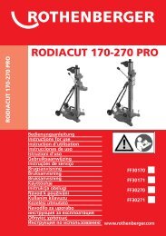
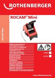
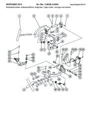
<strong>Vacuum</strong> <strong>Gauge</strong> <strong>Operation</strong><br />
Vakuumkabel<br />
<strong>Vacuum</strong> cable<br />
Cable de vide<br />
Vakuumsensor<br />
<strong>Vacuum</strong> gauge<br />
Capteur de vide<br />
Saugdruck (blau)<br />
to low side (blue)<br />
au cote basse pression (bleu)<br />
Hochdruck (rot)<br />
to high side (red)<br />
au cote haute pression<br />
(rouge)<br />
An die Vakuumpumpe<br />
to vacuum pump<br />
a la pompe a vide<br />
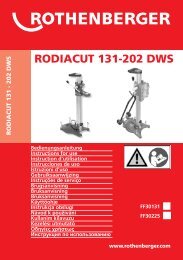
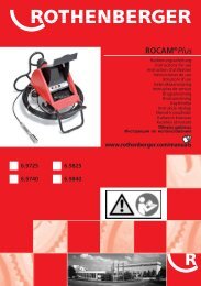
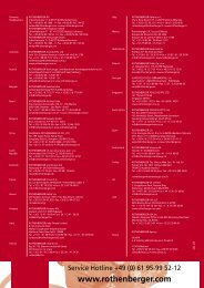
<strong>Measuring</strong> <strong>Actual</strong> Superheat and<br />
Subcooling<br />
To recovery<br />
or charging tank<br />
Liquid<br />
Vapor and Liquid<br />
Vapor<br />
Condenser<br />
Refrigerant flow<br />
Throttle Valve<br />
(TXV, Cap Tube, Fixed Orifice)<br />
Outside<br />
Indoor<br />
Compressor<br />
Outside<br />
Indoor<br />
Evaporator<br />
Liquid<br />
Vapor and Liquid<br />
Vapor<br />
To recovery<br />
or charging tank
Intro<br />
DEUTSCH<br />
Seite 2<br />
Bedienungsanleitung bitte lesen und aufbewahren! Nicht wegwerfen!<br />
Bei Schäden durch Bedienungsfehler erlischt die Garantie! Technische Änderungen vorbehalten!<br />
ENGLISH<br />
page 8<br />
Please read and retain these directions for use. Do not throw them away! The warranty does not cover<br />
damage caused by incorrect use of the equipment! Subject to technical modifications!<br />
FRANÇAIS<br />
page 14<br />
Lire attentivement le mode d’emploi et le ranger à un endroit sûr! Ne pas le jeter ! La garantie est<br />
annulée lors de dommages dûs à une manipulation erronée ! Sous réserve de modifications techniques!<br />
CE-KONFORMITÄTSERKLÄRUNG<br />
Wir erklären in alleiniger Verantwortung, dass<br />
dieses Produkt mit den angegebenen Normen und<br />
Richtlinien übereinstimmt.<br />
EC-DECLARATION OF CONFORMITY<br />
We declare on our sole accountability that this<br />
product conforms to the standards and guidelines<br />
stated.<br />
DECLARATION CE DE CONFORMITÉ<br />
Nous déclarons sous notre propre responsabilité que<br />
ce produit est conforme aux normes et directives<br />
indiquées.<br />
2004/108/EG<br />
EN 55011:1998 Teil 1, Klasse B<br />
EN 61000-6-1:2001<br />
EN 61000-6-3:2001<br />
EN 14624:2005<br />
ppa. Arnd Greding<br />
30.05.2008<br />
1
Inhalt Seite<br />
Technische Daten / Anwendungsbereiche 3<br />
Sicherheitshinweise 3<br />
Batteriewartung & Installation 3<br />
Batteriemontage 4<br />
Kalibrierung 4<br />
Einstellung von Kältemittel, Druck, Temperatur und automatische Ausschaltung 4<br />
Vakuumeinstellung 5<br />
Wichtige Hinweise beim Warten von Kälte/ Klima Anlagen 5<br />
Die Diagonistik vom Systemdruck und der Temperatur 5<br />
Das Befüllen 5<br />
Das Arbeiten der Vakuumanzeige Abb. A 5<br />
Tatsächliche Überhitzung/ Unterkühlungtemperaturmessung Abb. B 6<br />
Überhitzungstemperatur und Unterkühlungstemperaturziel 6<br />
Reinigen des Sensors 7<br />
Zubehör 7<br />
Entsorgung 7<br />
Kennzeichnungen in diesem Dokument<br />
Gefahr<br />
Dieses Zeichen warnt vor Personenschäden.<br />
Achtung<br />
Dieses Zeichen warnt vor Sach- oder Umweltschäden.<br />
� Aufforderung zu Handlungen<br />
2 DEUTSCH
Technische Daten / Anwendungsbereiche<br />
Druckdisplay: ............................................PSI, Bar, MPa, Kg/cm2<br />
Temperaturdisplay:.....................................°F oder °C<br />
Tiefvakuumdisplay: ....................................Micron, mBar, KPa, mmHg<br />
Auflösung: ................................................1 psi (.07 Bar, .007 MPa, .07 Kg/cm2)<br />
Genauigkeit: ..............................................+/- 1 psi oder 1% der Anzeige<br />
Arbeitsdruck: ............................................0 bis 750 psi (52 Bar, 5 MPa, 52 Kg/cm2)<br />
Prüfdruck: .................................................1000 psi (70 Bar, 7 MPa, 70 Kg/cm2) [Tolerierbarer Druck<br />
ohne interne Beschädigungen hervorzurufen]<br />
Kältemittel Temperaturmessbereich: ..........-40 bis 200°F (-4 bis 93°C)<br />
Arbeitstemperatur: ....................................32 bis 122°F (0 bis 45°C)<br />
Temperaturgenauigkeit: ............................±1°F (±0.5°C) zwischen 32 bis 160°F (0 to 71°C)<br />
Lagerungstemperatur: ...............................10 bis 120°F (12 bis 49°C)<br />
Anschlussverbindungen: ............................mit 1/4” SAE (7/16 UNF)<br />
Leistungsquelle: ........................................Spannung 9V mit Gleichstrombatterie und AC/DC Auflader,<br />
optional zu bestellen<br />
Lebensdauer der Batterie: ..........................30-36 Stunden Wartungsmodus (Druck- und Temperaturmessung)/<br />
25-30 Stunden Evakuiermodus und Einsatz von<br />
Hintergrundbeleuchtung<br />
Automatische Ausschaltung: .....................abstellbar für 15 Minuten<br />
Besondere Eigenschaften:<br />
• Automatische Aufwärmung<br />
• Schwach Batterie Anzeiger<br />
• Zeigt 61 unterschiedliche Kältemittel an<br />
• Zeigt den Druck, Sattdampf/Sensor Temperatur, Überhitzungs/Unterkühlungs Temperatur und<br />
Tiefvakuum<br />
• Mit Displaybeleuchtung zum bequemen Ablesen an dunklen Stellen<br />
• Mit 9V Gleichstrombatterie. AC/DC Auflader, optional zu bestellen<br />
• Monteurhilfe mit Aluminium Gehäuse, frei schwimmende Kolbenventile und Schauglas<br />
• Automatische Ausschaltung mit Abschaltemöglichkeit<br />
• Mit Gummischutz umhüllt<br />
• Aufhänger wird an der Rückseite weggesteckt<br />
Sicherheitshinweise<br />
Tragen Sie Sicherheitsbrille / Handschuhe.<br />
Bewahren Sie die Monteurhilfe an einem trockenem Ort.<br />
Vermeiden Sie Feuchtigkeit in dem Gerät.<br />
Lassen Sie die Kältemittel nicht in die Luft entfliehen.<br />
Wenn das Kältemittel in die Augen gerät, reinigen Sie Ihre Augen mit reichlich viel Wasser.<br />
Suchen Sie schnell wie möglichst einen Arzt auf.<br />
Batteriewartung & Installation<br />
Wenn die Batterie in das Gerät eingelegt worden ist und es nicht benutzt wird, beträgt die Lebensdauer<br />
6 Monate.<br />
Bitte beachten Sie: Um die Lebensdauer der 9V Batterie zu verlängern;<br />
a.) schalten Sie die Auto-Off Funktion ein<br />
b.) schalten Sie das Gerät ab, wenn Sie eine längeren Wartungs- und Inbetriebnahmeprozess<br />
durchführen und schalten Sie es nach Bedarf wieder ein (30-45 Sekunden beträgt danach die<br />
Wartezeit, bis Sie die korrekten Ergebnisse auf der Anzeige bekommen)<br />
DEUTSCH 3
Batteriemontage<br />
� Ziehen Sie den Batteriedeckel raus.<br />
� Vergewissern Sie sich, dass die Batterie in seine<br />
Stelle mit den richtigen Polspitzen plaziert ist.<br />
� Batteriedeckel wieder festmachen.<br />
Kalibrierung<br />
Für ein genaues Ablesen ist es wichtig, die Monteurhilfe zu kalibrieren.<br />
Bitte folgen Sie diesen Schritten, um die Kalibrierung durchzuführen.<br />
1. Drücken Sie POWER, um das Gerät einzuschalten.<br />
2. Geben Sie dem Gerät 10-15 Sekunden Zeit, um den Bereitschaftsmodus zu erreichen. (Alle Zeichen und<br />
Einheiten zählen abwärts 9999, 8888, 7777, …). Wenn die Initialisierung abgeschlossen ist, erscheint<br />
nur die Druck- und Temperaturanzeige.<br />
3. Da die Monteurhilfe den absoluten Druck anzeigt, muss sie kalibriert werden. Drücken Sie ENTER und<br />
halten Sie die Taste für 10-15 Sekunden gedrückt. Die Druckanzeige ist nun auf Null eingestellt.<br />
Bitte beachten Sie: In einigen Fällen ist die Druckanzeige nicht auf Null eingestellt, wenn die<br />
Monteurhilfe nicht mit der Klimasystem bzw. Vakuumpumpe verbunden ist. Drücken Sie ENTER für 10-<br />
15 Sekunden. Die Druckanzeige ist nun auf Null eingestellt.<br />
ACHTUNG! Falls die Monteurhilfe mit einem Klimasystem oder Vakuumpumpe verbunden ist und<br />
aktuelle Werte wiedergibt, versuchen Sie nicht das Gerät auf Null zu kalibrieren. Dies kann die Anzeige<br />
verfälschen.<br />
Einstellung von Kältemittel, Druck, Temperatur und automatische Ausschaltung<br />
� Um das Gerät anzuschalten, drücken Sie auf POWER.<br />
Warten Sie bis das Gerät den Bereitschaftsmodus erreicht hat [Kältemittel, Druck, Temperatur oder<br />
Vakuum werden angezeigt, wenn das Gerät bereit ist].<br />
� Drücken Sie SELECT, um in das Kältemittelmenü zu gelangen.<br />
� Drücken Sie erneut SELECT, bis das passende Kältemittel erscheint.<br />
[Die Kältemittelliste verändert sich nur in der Höhenrichtung. Kältemittel: R11, R12, R13, R21, R22,<br />
R23, R32, R113, R114, R115, R116, R123, R124, R125, R134, R134a, R141B, R142B, R143, R143A,<br />
R152A, R176, R218, R290, R401A, R401B, R401C, R402A, R402B, R403A, R403B, R404A, R405A,<br />
R406A, R407A, R407B, R407C, R407D, R408A, R409A, R410A, R410B, R411A, R411B, R412A,<br />
R413A, R414A, R414B, R501, R502, R503, R504, R507, R508B, R509A, R600, R600A, R601, R601A,<br />
R717, R744]<br />
� Um zu bestätigen, drücken Sie auf ENTER.<br />
In dem nächsten Schritt wird die Druckeinheit angezeigt.<br />
� Um die Druckeinheit zu verändern drücken Sie auf SELECT. Um zu bestätigen, drücken Sie auf ENTER.<br />
In dem nächsten Schritt wird die Temperatureinheit angezeigt.<br />
� Um °F oder °C Einheit zu wählen, drücken auf SELECT. Um zu bestätigen, drücken Sie auf ENTER.<br />
Im nächsten Schritt wird die automatische Ausschaltung angezeigt.<br />
� Um die Auto- Off (Automatische Ausschaltung) Funktion außer Betrieb zu setzen, drücken Sie auf<br />
SELECT (die automatische Ausschaltfunktion wird aus der Anzeige gelöscht).<br />
Wenn die automatische Ausschaltfunktion am Display angezeigt wird, wird sich die Monteurhilfe in 15<br />
Minuten ausschalten.<br />
� Um das Gerät wieder anzuschalten drücken Sie auf ON/OFF und warten Sie 15-20 Sekunden bis es<br />
aufgewärmt ist.<br />
HINWEIS: Um die Lebensdauer der Batterie zu verlängern, wird empfohlen die automatische<br />
Ausschaltfunktion in Betrieb zu lassen.<br />
4 DEUTSCH<br />
Batteriefach
Vakuumeinstellung<br />
� Schließen sie den Vakuumsensor an die Monteurhilfe und schalten<br />
Sie das Gerät an.<br />
Hinweis: Um den Vakuumsensor vom Gerät zu lösen, drücken Sie<br />
den Schnappverschluss unter dem Verbindungskabel. Das Ziehen am<br />
Kabel ohne den Schnappverschluss zu lösen, führt zu einem Schaden<br />
und kann nicht unter Garantie ersetzt werden (siehe Bild. 1).<br />
Bild. 1<br />
� Drücken Sie die VAKUUM Taste.<br />
� Um die gewünschte Einheit zu wählen drücken sie auf SELECT.<br />
� Um zu bestätigen, drücken Sie auf ENTER.<br />
Die Vakuumanzeige wird sich nach 15 Minuten automatisch schließen.<br />
� Um das Gerät anzuschalten, drücken Sie auf die ON/OFF und VAKUUM. Warten Sie 30- 45<br />
Sekunden bis der Sensor warm geworden und der tatsächlicher Vakuumwert angezeigt wird. (Falls<br />
Sie längere Wartungs- und Inbetriebnahmearbeiten durchführen, schalten Sie das Gerät ab<br />
und bei Bedarf wieder ein, um die Batterielebensdauer zu erhöhen)<br />
Wichtige Hinweise beim Warten von Kälte/ Klima Anlagen<br />
Ein System das geöffnet wurde, oder wo wegen Leckage Druckverlust vorhanden ist, muss erst entsorgt<br />
und dann evakuiert werden.<br />
Nach Reparatur muss es wieder auf Leckage geprüft, und vor der Füllung wieder evakuiert werden.<br />
Die Diagonistik vom Systemdruck und der Temperatur<br />
1. Achten Sie darauf, dass die zwei Ventile auf der Monteurhilfe geschlossen sind (drehen Sie die Ventile<br />
in Uhrzeigersinn).<br />
2. Verbinden Sie den blauen und roten Schlauch, die von der Nieder- und Hochdruckseite der<br />
Monteurhilfe rausgehen, an die Klimaanlage.<br />
3. Schalten Sie das System an und warten Sie ein wenig, bis der tatsächliche Druckwert in der<br />
Monteurhilfe angezeigt wird.<br />
Das Befüllen<br />
1. Beide Ventile an der Monteurhilfe müssen ganz geschlossen werden.<br />
2. Schalten Sie das System an.<br />
3. Verbinden Sie den gelben Schlauch an die Kältemittelflasche. (Verfolgen Sie für die richtige Dosierung<br />
die Anweisungen des Herstellers). Verwenden Sie für die richtige Füllung eine elektronische<br />
Kältemittelfüllwaage.<br />
4. Öffnen Sie langsam das Niederdruckventil der Monteurhilfe und fangen Sie mit der Füllung an.<br />
5. Wenn die Füllung zu Ende ist, schließen sie das Ventil auf die Kältemittelflasche und warten Sie bis die<br />
Kühlflüssigkeit aus den Schläuchen und Monteurhilfe entleert ist.<br />
6. Schließen Sie das Niederdruckventil der Monteurhilfe und trennen Sie den Schlauch (Schläuche) von<br />
dem System.<br />
Das Arbeiten der Vakuumanzeige Abb. A<br />
� Um das Gerät anzuschalten, drücken Sie auf POWER. Warten Sie 10 Sekunden bis es warm ist.<br />
� Schliessen Sie die beide Hähne.<br />
� Verbinden sie den Vakuumsensor an den seitlichen Anschluss der Monteurhilfe.<br />
� Verbinden Sie die andere Seite des Vakuumsensors an den seitlichen Verbindungsport der<br />
Monteurhilfe. Drücken Sie auf <strong>Vacuum</strong>.<br />
� Verbinden Sie Saug und Hochdruckschläuche an das System und den gelben Schlauch an die<br />
Vakuumpumpe.<br />
DEUTSCH 5
� Schalten Sie die Vakuumpumpe an und öffnen Sie das Ventil an die Saugseite.<br />
Das Zählen des Vakuumwertes nach hinten fängt von atmosphärischen Druck 00000 an. Gemäß den<br />
Systemgrößen, werden die Zeilen auf dem LCD Display erlöschen. Wenn alle Zeilen erlöscht sind, wird<br />
die zahlerische Lesevorrichtung am LCD Display erscheinen. Die Zahlen werden von 25000 MIKRON<br />
oder in anderen Einheiten heruntergesetzt.<br />
� Das Gerät wird nach 15 Minuten automatisch ausgeschaltet. Drücken Sie auf POWER.<br />
Warten Sie 30-45 Sekunden bis der Sensor warm geworden und der tatsächliche Vakuumwert<br />
angezeigt wird.<br />
� Wenn der gewünschte Vakuumwert erreicht ist, schließen Sie das Niederdruckventil und trennen Sie<br />
den Vakuumsensor von der Monteurhilfe.<br />
� Um das Gerät auszuschalten, drücken Sie auf POWER. (Falls Sie längere Wartungs- und<br />
Inbetriebnahmearbeiten durchführen, schalten Sie das Gerät ab und bei Bedarf wieder ein, um die<br />
Batterielebensdauer zu erhöhen)<br />
ACHTUNG!! Stoppen Sie niemals die Vakuumpumpe bevor Sie die Vakuumanzeige außer Betrieb<br />
gesetzt haben. Wenn diese Anweisung nicht befolgen wird, kann Öl in die Sensorzelle geraten.<br />
Tatsächliche Überhitzung/ Unterkühlungtemperaturmessung Abb. B<br />
Die Überhitzung, ist der Unterschied zwischen der tatsächlichen Temperatur des Kältemittels (Gas)<br />
beim Verlassen des Verdampfers und der Siedepunktemperatur des Kältemittels in der<br />
Verdampferspirale.<br />
Wenn der Siedepunkt erreicht ist, setzt sich die Aufwärmung des Kühlmittels fort.<br />
Überhitzung ist die zusätzliche Aufheizung des Kältemittels nach Erreichen des Siedepunktes. Bei sehr<br />
schlechten Bedingungen (bei unzureichend gefüllten Systemen), verdampft das Kühlmittel erst am<br />
Verdampferaustritt vollständig.<br />
Um sicher zu sein, dass das flüssige Kältemittel bei schlechtesten Bedingungen nicht in den Kompressor<br />
gelangt, veröffentlichen die Klimageräte Hersteller Diagramme. Die Diagramme zeigen wie hoch die<br />
Überhitzungstemperatur sein soll bei einen bestimmten Luftfeuchtigkeit und Lufttemperatur. Die<br />
Messung der Überhitzung ergibt den besten Hinweis auf eine korrekte Kältemittelfüllmenge und<br />
ordentliches Funktionieren der Anlage.<br />
Wenn alles andere richtig arbeitet und die tatsächliche Überhitzung zu hoch ist, fügen Sie Kühlmittel in<br />
das System zu.<br />
Wenn die tatsächliche Überhitzung zu niedrig ist, vermindern Sie das Kühlmittel im System.<br />
Die Unterkühlungstemperatur, ist der Unterschied zwischen den Kältemittel im Kondensator und des<br />
Kältemittels beim Verlassen des Kondensators. Die Differenz um die das Kältemittel unter den<br />
Siedepunkt abkühlt, wird Unterkühlungstemperatur genannt.<br />
Wenn die Unterkühlungstemperatur zu hoch wird, kann flüssiges Kältemittel wieder in den<br />
Kompressor zurückfließen und Schaden oder Fehler verursachen.<br />
Achtung! Seien Sie vorsichtig wenn Sie mit Elektrik und mit Kältemittel unter Hochdruck<br />
arbeiten. Tragen Sie immer eine Schutzbrille.<br />
Folgen sie alle Anweisungen für die gewarteten oder montierten Anlagen.<br />
Überhitzungstemperatur und Unterkühlungstemperaturziel<br />
Folgen Sie allen technischen Eigenschaften, Hinweisen und den Anregungen des Herstellers. Um die<br />
Zielwerte bei Überhitzungstemperatur und Unterkühlungstemperatur zu bestimmen, benötigen Sie<br />
generell drei Werte.<br />
Außenlufttemperatur, Innenluftfeuchte und das Herstellerdiagram für Überhitzungstemperatur oder<br />
Unterkühlungstemperatur.<br />
6 DEUTSCH
Reinigen des Sensors<br />
Kontrollieren Sie nach jedem Vakuumverfahren<br />
den Dichtungsring. Wenn Öl vorhanden ist,<br />
besteht die Möglichkeit, des Vorhandenseins des<br />
Öles in der Sensorkammer.<br />
Folgen Sie diese Anweisungen:<br />
1. Trennen Sie die Sensorzelle vom Sockel.<br />
2. Entfernen Sie den Dichtungsring &<br />
Ventilkerndrücker für die Reinigung.<br />
3. Reinigen Sie den Dichtungsring. Spülen Sie<br />
die Sensorzelle mit Azeton<br />
Ventilkerndrucker<br />
Dichtung<br />
¼“ FL-F<br />
Drehmutter<br />
Wiederholen Sie den Vorgang, bis das Öl vollkommen entfernt ist. Gewähren Sie 2-4 Stunden damit alle<br />
Teile getrocknet sind.<br />
4. Bringen Sie alle Teile wieder zusammen und kontrollieren Sie die Vorrichtung<br />
Zubehör<br />
Geeignetes Zubehör und ein Bestellformular finden Sie ab Seite 20.<br />
Sensorleitung<br />
Sensorzelle<br />
Sockel<br />
Entsorgung<br />
Teile des Gerätes sind Wertstoffe und können der Wiederverwertung zugeführt werden. Hierfür stehen<br />
zugelassene und zertifizierte Verwerterbetriebe zur Verfügung. Zur umweltverträglichen Entsorgung der<br />
nicht verwertbaren Teile (z.B. Elektronikschrott) befragen Sie bitte Ihre zuständige Abfallbehörde.<br />
Nur für EU-Länder:<br />
Werfen Sie Elektrowerkzeuge nicht in den Hausmüll! Gemäß der Europäischen Richtlinie<br />
2002/96/EG über Elektro- und Elektronik-Altgeräte und ihrer Umsetzung in nationales Recht<br />
müssen nicht mehr gebrauchsfähige Elektrowerkzeuge getrennt gesammelt und einer<br />
umweltgerechten Wiederverwertung zugeführt werden.<br />
Nur für Deutschland gültig:<br />
Die Entsorgung Ihres erworbenen ROTHENBERGER Gerätes übernimmt ROTHENBERGER für Sie -<br />
kostenlos! Bitte geben Sie dies bei Ihrem nächsten ROTHENBERGER Service Express Händler ab. Wer Ihr<br />
ROTHENBERGER Service Express Händler in Ihrer Nähe ist, erfahren Sie auf unserer Homepage unter<br />
www.rothenberger.com<br />
Kabel<br />
DEUTSCH 7
Contents page<br />
Technical data / specifications 9<br />
Warning 9<br />
Battery care & installation 9<br />
Battery installation 10<br />
Pressure adjustment for elevation 10<br />
Setting refrigerant, pressure, temperature and auto-off 10<br />
Setting vacuum 11<br />
Important notes for servicing AC/R system 11<br />
Diagnosing the system pressure and temperature 11<br />
Charging 11<br />
<strong>Vacuum</strong> gauge operation fig. A 12<br />
<strong>Measuring</strong> actual superheat and subcooling fig. B 12<br />
Target superheat and subcooling 13<br />
Cleaning the sensor 13<br />
Accessories 13<br />
Disposal 13<br />
Markings in this document<br />
Danger<br />
This sign warns against the danger of personal injuries.<br />
Caution<br />
This sign warns against the danger of property damage and damage to<br />
the environment.<br />
� Call for action<br />
8 ENGLISH
Technical data / specifications<br />
Pressure Display: ....................................... PSI, Bar, MPa, Kg/cm2<br />
Temperature Display: ................................. °F or °C<br />
Deep <strong>Vacuum</strong> Display: .............................. Mikron, mBar, KPa, mmHg<br />
Sensing Resolution: ................................... 1 psi (.07 Bar, .007 MPa, .07 Kg/cm2)<br />
Sensing Accuracy: ...................................... ±1 psi or 1% of reading (whichever is greater)<br />
Working Pressure: ..................................... 0 to 750 psi (52 Bar, 5 MPa, 52 Kg/cm2)<br />
Proof Pressure: .......................................... 1000 psi (70 Bar, 7 MPa, 70 Kg/cm2) [Tolerable pressure<br />
without internal damage]<br />
Refrigerant Temperature Range: ............... -40 to 200°F (-4 bis 93°C)<br />
Operating Temperature: ............................ 32 to 122°F (0 bis 45°C)<br />
Temperature Accuracy: ............................. ±1°F (±0.5°C) between 32 to 160°F (0 to 71°C)<br />
Storage Temperature: ............................... 10 to 120°F (12 to 49°C)<br />
Connections: ............................................. 1/4” SAE ( 7/16“ UNF)<br />
Power: ...................................................... 9V DC battery with optional AC/DC adapter<br />
Battery Life: ............................................... 30-36 hours hours pressure and temperature mode only<br />
(continuous use), 25-30 hours vacuum and backlight mode<br />
(continuous use)<br />
Auto-Off: .................................................. 15 min. with disabling capability<br />
Special features:<br />
• Low battery indicator<br />
• Displays 61 refrigerants<br />
• Displays pressure, saturated/sensor temperature, superheat/subcool temperature and deep vacuum<br />
• Includes back-lit display for easy reading in darker areas<br />
• 9V DC battery with optional AC/DC adapter<br />
• Free .oating piston seal seat aluminum block with sight glass<br />
• Auto-Off with disabling capability<br />
• Protective rubber boot<br />
• Heavy duty hook folds into back of unit<br />
Warning<br />
Wear Safety Glasses / Wear Gloves.<br />
Keep the manifold in a dry place. Do not allow moisture to enter the unit.<br />
Do not vent refrigerant into the atmosphere.<br />
If eyes come in contact with refrigerant, immediately flush with plenty water. Seek medical<br />
attention immediately.<br />
Battery care & installation<br />
When the battery is connected to the unit but not in use it will last six months.<br />
Note: In order to prolong the life of the 9V battery;<br />
a.) keep auto-off function enabled<br />
b.) if pressure, temperature or deep vacuum is being used for an extended period of time turn the unit<br />
off and turn back on again when reading is required. (Allow 30-45 seconds for the correct reading to<br />
appear.)<br />
ENGLISH 9
Battery installation<br />
� Remove the battery compartment cover.<br />
� Make sure to place the battery into the<br />
compartment with the correct polarity.<br />
� Replace battery cover.<br />
Pressure adjustment for elevation<br />
For an accurate reading, it is important to adjust the manifold for elevation and barometric pressure.<br />
Follow these steps to set the unit for local elevation and barometric readings.<br />
1. Press the POWER button to turn the unit ON.<br />
2. Allow 10-15 seconds for unit to initialize. (You will see all characters and units countdown<br />
99999,88888,77777... ) Once initialization is complete, only pressure and temperature readings will<br />
appear.<br />
3. Since the manifold reads absolute pressure it must be set for local elevation and barometric readings.<br />
Press and hold the ENTER button for 10-15 seconds and release. Pressure readings will now be truly<br />
zero.<br />
NOTE: In some cases pressure reading may not be zero with the manifold disconnected from the<br />
pressure or vacuum source. Press and hold the ENTER button for 10-15 seconds and release. Pressure<br />
readings will now be zero.<br />
WARNING! If the manifold is connected to a pressure or vacuum source and displays actual readings,<br />
do not attempt to zero out the reading by pressing the enter button. This can offset the reading.<br />
Setting refrigerant, pressure, temperature and auto-off<br />
� Press the POWER button to turn the unit ON.<br />
Wait for the unit to initialize [a refrigerant, pressure, temperature or vacuum will be displayed when<br />
the unit is ready].<br />
� Press the SELECT button to access the refrigerant menu.<br />
� Press SELECT again to display refrigerant type.<br />
[The Refrigerant list ascends only. Refrigerants: R11, R12, R13, R21, R22, R23, R32, R113, R114, R115,<br />
R116, R123, R124, R125, R134, R134a, R141B, R142B, R143, R143A, R152A, R176, R218, R290,<br />
R401A, R401B, R401C, R402A, R402B, R403A, R403B, R404A, R405A, R406A, R407A, R407B,<br />
R407C, R407D, R408A, R409A, R410A, R410B, R411A, R411B, R412A, R413A, R414A, R414B, R501,<br />
R502, R503, R504, R507, R508B, R509A, R600, R600A, R601, R601A, R717, R744]<br />
� Press ENTER to confirm.<br />
Next the Pressure Unit will display.<br />
� Press the SELECT button to change the pressure unit. Press ENTER to confirm.<br />
Next the Temperature Unit will display.<br />
� Press the SELECT button to either °F or °C. Press ENTER to confirm.<br />
Next Auto-Off will display.<br />
� Press the SELECT button to disable Auto-Off [auto-off will clear from the display.].<br />
If the auto-off feature is displayed the manifold will shut down after 15 minutes.<br />
� Press the ON/OFF button to turn the unit back on and allow 15-20 seconds to initialize.<br />
NOTE: It is recommended to keep the auto-off feature enabled to save the<br />
life of the battery.<br />
10 ENGLISH<br />
Battery<br />
compartment
Setting vacuum<br />
� Connect the vacuum sensor cable to the manifold and turn the unit<br />
on.<br />
Note: To disconnect the vacuum sensor cable be sure to press the<br />
release latch under the connector cable. Pulling on the cable without<br />
disengaging the latch will cause damage and is not replaceable<br />
under warranty (see fig1).<br />
fig. 1<br />
� Press the VACUUM button. This will phase out the temperature display and only show the vacuum<br />
units.<br />
� Press the SELECT button until the desired vacuum unit is displayed.<br />
� Press ENTER to confirm.<br />
The vacuum display will go off after 15 minutes automatically.<br />
� Press the ON/OFF button and VACUUM button to turn the unit on. Allow 30-45 seconds for the<br />
sensor to warm up and the correct vacuum reading to appear. (If pressure, temperature or deep<br />
vacuum is being used for an extended period of time turn the unit off and turn back on<br />
again when reading is required.)<br />
Important notes for servicing AC/R system<br />
A system that has been opened or one that is found to be excessively low on refrigerant pressure as a<br />
result of a leak, must be fully evacuated by means of recovery/recycling and deep vacuum.<br />
A system that has been evacuated must be repaired, leak tested and evacuated again before charging.<br />
Diagnosing the system pressure and temperature<br />
1. Make sure both valves on the manifold are closed (turn knobs clockwise).<br />
2. Connect the blue and red hose from the low and high side of the manifold to the system.<br />
3. Start the system and allow some time for the true pressure reading on the manifold to appear and<br />
stabalize.<br />
Charging<br />
1. Verify that both valves on the manifold are shut completely.<br />
2. Turn the system on.<br />
3. Connect the other end of the yellow hose to Refrigerant Gas supply. (Follow refrigerant<br />
manufacturer’s instructions for proper dispensing.). Use an electronic scale for accurate charging<br />
4. Open manifold low side (blue) valve slowly and start charging.<br />
5. When charging is .nished, close the valve on the tank and allow some time for the refrigerant to be<br />
evacuated from the hoses and manifold.<br />
6. Close the low side valve and disconnect the hose(s) from the system.<br />
ENGLISH 11
<strong>Vacuum</strong> gauge operation fig. A<br />
� Press the POWER button to turn the unit ON. Allow 10 seconds for the unit to initialize.<br />
� Close both valves.<br />
� Connect the vacuum cable to the manifold.<br />
� Connect the other end of the vacuum gauge to the side port on the manifold. Press the VACUUM<br />
button.<br />
� Connect the high side and low side hoses to the system and the yellow hose to the vacuum pump.<br />
� Start the vacuum pump and open the low side valve.<br />
The vacuum countdown will start from atmospheric pressure 00000. Depending on the size of the<br />
system, the lines on the LCD display will disappear one by one. Once all lines have disappeared, the<br />
numerical reading will appear on the LCD. The numbers descend from 25000 MICRONS or<br />
corresponding units.<br />
� The unit will shut down after 15 minutes automatically. Press the POWER button again.<br />
Allow 30-45 seconds for initializing and the correct vacuum reading to appear.<br />
� Once the target vacuum is reached, close the low side valve and disconnect the vacuum gauge port<br />
from the manifold.<br />
� Press the POWER button to turn the unit off. (If pressure, temperature or deep vacuum is being<br />
used for an extended period of time turn the unit off and turn back on again when reading<br />
is required)<br />
WARNING!! Never stop the vacuum pump unless the vacuum gauge is disconnected. Failure to<br />
do so may cause oil to enter the sensor chamber.<br />
<strong>Measuring</strong> actual superheat and subcooling fig. B<br />
Superheat is the difference between the actual temperature (sensor temperature) of the refrigerant<br />
(gas) as it leaves the evaporator and the boiling point temperature of the refrigerant in the evaporator<br />
coil (saturated temperature).<br />
After boiling, the refrigerant continues to warm up.<br />
The number of degrees it “warmed up” after boiling is called the superheat. Under worst-case<br />
conditions (low load for fixed orifice systems), the refrigerant in the evaporator boils off near the end of<br />
the evaporator coil.<br />
To make sure liquid doesn’t enter the compressor under the worst case condition, the AC manufacturers<br />
publish charts. The charts indicate what the superheat should be at a given indoor wet bulb<br />
measurement and outdoor air temperature. <strong>Measuring</strong> superheat is your best indication on a fixed<br />
orifice system of the proper refrigerant charge and operating conditions.<br />
If everything else is working properly and the actual superheat is too high, add refrigerant. If it’s too low,<br />
remove refrigerant.<br />
Subcooling is the difference between the boiling point of the refrigerant in the condenser (saturated<br />
temperature) and the actual temperature (sensor temperature) of the refrigerant as it leaves the<br />
condenser. The degrees that the refrigerant “cools down” below the boiling point is the sub-cooling.<br />
Under worst case scenario low load for thermostatic expansion valve systems (TXV) the subcooling will<br />
continue to rise.<br />
If the subcooling rises too high, liquid may be backed into the compressor causing damage and failure.<br />
WARNING! Use caution whenever working with electricity and high-pressure liquid or gas.<br />
Always wear safety glasses.<br />
Follow all instructions provided with equipment being serviced or installed.<br />
12 ENGLISH
Target superheat and subcooling<br />
Follow all equipment manufacturer’s speci.cations, warnings and suggestions. To determine the target<br />
superheat (.xed ori.ce system) or subcooling (charts vary dramatically from one system to another), you<br />
will typically need three things.<br />
Outdoor dry bulb (outdoor air temperature), indoor wet bulb, and the manufacturers target superheat<br />
chart or subcooling chart.<br />
Cleaning the sensor<br />
Observe the gasket after each vacuum. If oil is<br />
present, it is possible that there is a presence of<br />
oil in the sensor chamber.<br />
Follow these instructions:<br />
1. Disconnect the sensor chamber from the<br />
socket.<br />
2. Remove the gasket & depressor from the<br />
assembly to clean.<br />
Depressor<br />
Gasket<br />
¼“ FL-F<br />
Sensor chamber<br />
Cable<br />
Swivel nut<br />
3. Clean the gasket. Rinse the sensor chamber with acetone<br />
Sensor tube Socket<br />
Repeat until the oil is completely removed. Allow 2 – 4 hours for all of the parts to dry.<br />
4. Reassemble all of the parts and check the unit.<br />
Accessories<br />
The relevant accessories and an order form can be found from page 20 onwards.<br />
Disposal<br />
Components of the unit are recyclable material and should be put to recycling. For this purpose registered<br />
and certified recycling companies are available. For an environmentalfriendly disposal of the nonrecyclable<br />
parts (e.g. electronic waste) please contact your local waste disposal authority.<br />
For EU countries only:<br />
Do not dispose of electric tools with domestic waste. In accordance with European Directive<br />
2002/96/EC on waste electrical and electronic equipment and its implementation as national<br />
law, electric tools that are no longer serviceable must be collected separately and utilised for<br />
environmentally compatible recycling.<br />
ENGLISH 13
Table des matières Page<br />
Données techniques / Domaines d’application 15<br />
Avertissement 15<br />
Entretien et installation de la batterie 15<br />
Installation de pile 15<br />
Ajustement de la pression pour l’élévation 16<br />
Reglage de refrigerant, pression, temperature et arret automatique 16<br />
Selectionner unites de vide 16<br />
Notes importantes pour la revision d’un systeme AC/R 17<br />
Diagnostiquer pression et temperature du systeme R/AC 17<br />
Charge 17<br />
Fonctionnement indicateur de vide Fig. A 17<br />
Mesure des temperatures actuelles de surchauffe et sousrefroidissement Fig. B 18<br />
Surchauffe et sous-refroidissement cible 18<br />
Nettoyage du capteur 18<br />
Accessoires 19<br />
Elimination des déchets 19<br />
Pictogrammes contenus dans ce document<br />
Danger<br />
Ce pictogramme signale un risque de blessure pour les personnes.<br />
Attention<br />
Ce pictogramme signale un risque de dommage matériel ou de préjudice<br />
pour l’environnement.<br />
� Nécessité d’exécuter une action<br />
14 FRANÇAIS
Données techniques / Domaines d’application<br />
Affichage pression: ................................... PSI, Bar, MPa, Kg/cm2<br />
Affichage température:.............................. °F ou °C<br />
Affichage Vide Profond: Micron: ............... Mikron, mBar, KPa, mmHg<br />
Résolution de détection : .......................... 1 psi (.07 Bar, .007 MPa, .07 Kg/cm2)<br />
Précision de détection : .............................. +/- 1 psi ou 1% de l’affichage (la valeur la plus élevée<br />
Pression d’utilisation : ................................ 0 à 750 psi (52 Bar, 5 MPa, 52 Kg/cm2)<br />
Pression de test : ....................................... 1000 psi (70 Bar, 7 MPa, 70 Kg/cm2) [Pression tolérable sans<br />
risque d’endommagement intérieur]<br />
Plage de Mesure Température Réfrigérant: -40 à 200°F (-4 à 93°C)<br />
Température Opérationnelle: .................... 32 à 122°F (0 à 45°C)<br />
Précision de température : ......................... ±1°F (±0.5°C) 32 à 160°F (0 to 71°C)<br />
Température de stockage : ........................ 10 à 120°F (12 à 49°C)<br />
Branchements: .......................................... 1/4” SAE (7/16“ UNF)<br />
Alimentation: ............................................ Pile 9V DC avec l’adaptateur AC/DC optionnel<br />
Vie de pile: ................................................ 30-36 heures en mode pression et température (utilisation<br />
continue)/ 25-30 heures en mode vide et rétro éclairage<br />
(utilisation continue)<br />
Arrêt automatique: ................................... après 15 minutes avec la possibilité d’annulation<br />
Caracteristiques:<br />
• Indicateur de pile faible<br />
• Affiche 61 réfrigérants<br />
• Affiche la pression, la température saturée/actuelle, la température de surchauffe/de<br />
sousrefroidissement et le vide profond<br />
• Inclut un écran à fond éclairé pour la lecture facile dans des endroits plus obscures<br />
• Pile 9V DC avec l’adaptateur AC/DC optionnel<br />
• Manifold en aluminium avec voyant et vannes à piston de mouvement libre<br />
• Arrêt automatique qui est susceptible d’être annulé<br />
• Enveloppe protectrice en caoutchouc<br />
• Crochet de .xation rétractable<br />
Avertissement<br />
• Porter des lunettes de protection / Mettre des gants<br />
• Stocker le manifold en un endroit sec. Ne pas laisser entrer de l’humidité dans l’appareil.<br />
• Ne pas évacuer le .uide frigorigène à l’environnement.<br />
• Si les yeux viennent au contact avec du réfrigérant, nettoyer immédiatement à grande eau. Se présenter<br />
immédiatement à un examen médical.<br />
Entretien et installation de la batterie<br />
Durée de la batterie connectée à l’unité mais hors fonctionnement : 6 mois.<br />
Nota: afin de prolonger la vie de la batterie 9V ;<br />
a.) permettre la fonction ‘arrêt automatique’<br />
b.) En cas d’utilisation prolongée de la fonction pression, température ou vide, arrêter l’unité et<br />
redémarrer lorsque l’affichage est souhaité (attendre 30 à 45 secondes jusqu’au retour de l’affichage<br />
correct)<br />
Installation de pile<br />
� Enlever le couvercle de compartiment pile.<br />
� Assurer l’implantation de la pile dans le<br />
Compartiment<br />
compartiment pile avec la polarité correcte.<br />
Pile<br />
� Remplacer le couvercle de compartiment pile.<br />
FRANÇAIS 15
Ajustement de la pression pour l’élévation<br />
Afin de permettre un affichage précis il est important d’ajuster le manomètre pour l’élévation et la<br />
pression barométrique.<br />
Respecter les étapes suivantes pour régler l’unité sur élévation locale et affichage barométrique.<br />
1. Appuyer sur la touche POWER pour démarrer l’unité.<br />
2. Attendre l’initialisation 10 à 15 secondes (Apparition de tous les caractères en compte à rebours<br />
9999 … ) Lorsque l’initialisation est terminée, l’affichage de la pression et de la température apparaît.<br />
3. Etant donné que le manifold affiche la pression absolue, il doit être réglé pour l’élévation locale et<br />
l’affichage barométrique. Presser et tenir enfoncée la touche ENTER pour 10 à 15 secondes et relâcher.<br />
L’affichage de la pression est à zéro.<br />
NOTA : Dans certains cas l’affichage de pression peut ne pas être zéro lorsque le manifold est<br />
déconnecté de la source de pression et de vacuum. Presser et tenir enfoncé la touche ENTER pour 10 à<br />
15 secondes et relâcher. L’affichage de pression est à zéro.<br />
ATTENTION ! Si le manifold est connecté à une source de pression ou de vacuum et affiche les<br />
valeurs actuelles, ne pas essayer de mettre l’affichage à zéro en appuyant sur la touche. Ceci peut<br />
suspendre l’affichage.<br />
Reglage de refrigerant, pression, temperature et arret automatique<br />
� Pousser le bouton POWER pour allumer l’appareil.<br />
Attendre l’initialisation (affichage d’un frigorigène, de la pression, de la température ou du vide<br />
lorsque l’unité est prête).<br />
� Appuyer sur la touche SELECT pour accéder au menu Frigorigènes.<br />
� Appuyer de nouveau sur SELECT pour afficher le type de frigorigène.<br />
[La liste des réfrigérants n’avance qu’en sens montant. Les réfrigérants: R11, R12, R13, R21, R22, R23,<br />
R32, R113, R114, R115, R116, R123, R124, R125, R134, R134a, R141B, R142B, R143, R143A, R152A,<br />
R176, R218, R290, R401A, R401B, R401C, R402A, R402B, R403A, R403B, R404A, R405A, R406A,<br />
R407A, R407B, R407C, R407D, R408A, R409A, R410A, R410B, R411A, R411B, R412A, R413A,<br />
R414A, R414B, R501, R502, R503, R504, R507, R508B, R509A, R600, R600A, R601, R601A, R717,<br />
R744]<br />
� Pousser ENTER pour valider.<br />
Puis l’Unité de Pression sera affichée.<br />
� Pousser le bouton SELECT a.n de changer l’unité de pression. Pousser ENTER pour valider.<br />
Puis l’Unité de Température sera affichée.<br />
� Pousser le bouton SELECT a.n de sélectionner °F ou °C. Pousser ENTER pour valider.<br />
� Puis Auto-Off (Arrêt Automatique) sera affiché, Pousser le bouton SELECT afin d’annuler la fonction<br />
Auto-Off [« auto-off » sera supprimé de l’écran].<br />
Si la fonction Arrêt Automatique est affichée, le manifold va s’éteindre après 15 minutes.<br />
� Simplement pousser le bouton ON/OFF afin d’allumer de nouveau l’appareil et permettre 15-20<br />
secondes pour échauffement et lecture initialiser à la place du préchauffage dans la phase mentionnée<br />
ci-dessus.<br />
NOTE: Il est recommandé de maintenir la fonction arrêt automatique active pour prolonger la vie de pile.<br />
Selectionner unites de vide<br />
� Connecter le câble de capteur de vide au manifold et mettre<br />
l’appareil en marche.<br />
Nota: Pour déconnecter le câble de la sonde vacuum, appuyer sur le<br />
loquet sur le câble de connexion. Tirer sur le câble sans avoir détaché<br />
le loquet peut causer des dommages dont la remise en état ne sera<br />
pas prise en charge par la garantie (voir image 1).<br />
image 1<br />
� Pousser le bouton VACUUM. Cela supprime l’affichage de la température et indique seulement les<br />
unités de vide.<br />
� Pousser le bouton SELECT afin de sélectionner l’unité désirée.<br />
16 FRANÇAIS
� Pousser ENTER pour valider.<br />
L’affichage de vide va s’éteindre après 15 minutes automatiquement.<br />
� Pousser le bouton ON/OFF et le bouton VACUUM a.n d’allumer l’unité. Permettre 30-45 secondes<br />
pour l’échauffement du capteur de vide et l’apparition de la valeur exacte de vide sur l’écran. (En cas<br />
d’utilisation prolongée de la fonction pression, température ou vide, arrêter l’unité et<br />
remettre en route lorsque l’affichage est réclamé)<br />
Notes importantes pour la revision d’un systeme AC/R<br />
Un système qui a été ouvert ou encore qui à cause d’une fuite af.che une pression de réfrigérant très<br />
basse, doit être entièrement vidé par un recyclage/recovery et la mise à vide profond.<br />
Un système mis à vide doit être réparé, véri.é pour des fuites et encore une fois remis à vide avant de<br />
charger.<br />
Diagnostiquer pression et temperature du systeme R/AC<br />
1. Vérifier que les deux vannes manuelles sur le manifold sont bien fermées (tourner les deux boutons<br />
des vannes dans le sens des aiguilles d’une montre).<br />
2. Raccorder le flexible de basse pression (bleu) au côté aspiration du système, et le .exible de haute<br />
pression (rouge) au côté de refoulement du système.<br />
3. Démarrer le système R/AC et permettre un certain temps avant de voir apparaître la lecture numérique<br />
de la pression exacte sur l’écran afin de stabiliser.<br />
Charge<br />
1. Vérifier si les deux vannes manuelles sur le manifold à manomètre sont bien fermées.<br />
2. Mettre le système R/AC en marche.<br />
3. Raccorder le flexible jaune à la bouteille de gaz (Respecter les instructions des fabricants pour la<br />
distribution correcte). Faire usage d’une balance de réfrigérant électronique pour la charge exacte.<br />
4. Ouvrir la vanne côté basse pression (bleu) légèrement et débuter la charge.<br />
5. Lorsque la charge est terminée, fermer la vanne sur la bouteille et permettre un certain temps pour<br />
laisser évacuer tout le réfrigérant restant dans les flexibles et le manifold.<br />
6. Fermer la vanne côté basse pression et déconnecter le flexible (les flexibles) du système.<br />
Fonctionnement indicateur de vide Fig. A<br />
� Pousser le bouton POWER pour allumer l’unité. Permettre 10 secondes pour l’échauffement.<br />
� Fermer les deux vannes.<br />
� Connecter le cordon de vide au manifold.<br />
� Connecter le cordon de vide au manifold. Connecter le capteur même à la porte latérale sur le<br />
manifold. Pousser le bouton VACUUM.<br />
� Raccorder les flexibles côtés basse et haute pression au système ainsi que le flexible jaune à la pompa<br />
à vide.<br />
� Démarrer la pompe à vide et ouvrir la vanne côté basse pression.<br />
La compte à rebours du vide part de la pression atmosphérique 00000. Dépendant du volume du<br />
système, les lignes sur l’écran LCD vont disparaître. une à une. Une fois toutes les lignes supprimées,<br />
l’indicateur numérique lumineux va apparaître sur l’écran LCD. Les nombres commencent et<br />
descendent à partir de 25000 MICRONS ou équivalence en autres unités.<br />
� L’appareil va s’éteindre après 15 minutes automatiquement. Repousser le bouton POWER.<br />
Permettre 30-45 secondes pour l’échauffement et l’apparition de la valeur exacte du vide sur l’écran.<br />
� Une fois le vide cible achevé, fermer la vanne côté basse pression et déconnecter l’indicateur de vide<br />
du manifold.<br />
� Pousser le bouton POWER pour arrêter l’appareil. (En cas d’utilisation prolongée de la fonction<br />
pression, température ou vide, arrêter l’unité et remettre en route lorsque l’affichage est réclamé)<br />
AVERTISSEMENT!! Ne jamais arrêter la pompe à vide sans avoir découplé l’indicateur de vide.<br />
Dans le cas contraire, de l’huile peut s’in.ltrer dans la chambre de capteur.<br />
FRANÇAIS 17
Mesure des temperatures actuelles de surchauffe et sousrefroidissement Fig. B<br />
La température de surchauffe est la différence entre la température actuelle (température de<br />
capteur) du réfrigérant (gaz) lorsqu’il sort de l’évaporateur et la température du point d’ébullition du<br />
réfrigérant dans le serpentin d’évaporateur (température saturée).<br />
Après l’ébullition, le réfrigérant continue à s’échauffer.<br />
Le nombre de degrés gagné au cours de la phase “échauffement” après le point d’ébullition est appelé<br />
la surchauffe. Sous les pires conditions (charge faible pour les systèmes à orifice fixe), le réfrigérant dans<br />
l’évaporateur cesse de bouillir vers la fin du serpentin d’évaporateur.<br />
Afin de s’assurer que le liquide n’entre pas dans le compresseur sous la pire condition, les fabricants de<br />
climatisation publient les diagrammes. Les diagrammes indiquent quelle valeur doit-elle prendre la<br />
surchauffe à une température de bulbe humide interne et à une température d’air externe. Le calcul de<br />
la surchauffe est votre meilleure indication sur le système à orifice fixe avec la charge de réfrigérant et les<br />
conditions de fonctionnement correctes. Si tous les autres paramètres sont normaux et la surcharge<br />
actuelle est très haute, remplir du réfrigérant.<br />
Si la surcharge actuelle est très basse, enlever du réfrigérant. La température de sous-refroidissement est<br />
la différence entre la température du point d’ébullition du réfrigérant dans le condenseur (température<br />
saturée) et la température actuelle du réfrigérant (température de capteur) lorsqu’il sort du condenseur.<br />
Les degrés que le réfrigérant “refroidit” au-dessous du point d’ébullition s’appelle le sous-refroidissement.<br />
Sous le pire scénario la charge insuffisante pour les systèmes à détenteur thermostatique (TXV) la<br />
température de sous-refroidissement va continuer de monter. Lorsque la température de<br />
sousrefroidissement monte excessivement, le liquide peut reculer dans le compresseur entraînant le<br />
dommage et la défaillance.<br />
ATTENTION! Soyez prudent chaque fois que vous travaillez en présence de l’électricité et de<br />
liquide ou gaz haute pression. Porter toujours des lunettes de protection.<br />
Suivre toutes les instructions fournies avec l’équipement en phase d’entretien ou de montage<br />
Surchauffe et sous-refroidissement cible<br />
Suivre tous les spécifications, avertissements et recommandations des fabricants d’équipement. Afin de<br />
déterminer la surchauffe (système à orifice fixe) ou le sousrefroidissement (diagrammes changent<br />
énormément d’un système à autre) cible, vous aurez typiquement besoin de trois paramètres. La<br />
température au thermomètre sec externe (température d’air externe), la température de bulbe humide<br />
interne et le diagramme de surchauffe ou de sous-refroidissement cible des fabricants.<br />
Nettoyage du capteur<br />
Vérifier le joint après chaque usage. S’il y a de<br />
l’huile sur le joint, l’on peut assumer la présence<br />
d’huile dans la chambre de capteur.<br />
Suivre ces instructions:<br />
1. Déconnecter la chambre de capteur de la<br />
douille.<br />
2. Enlever le joint et le dépresseur de<br />
l’assemblage pour les nettoyer.<br />
Depresseur<br />
Joint<br />
¼“ FL-F Raccord<br />
Orientable<br />
Chambre de<br />
Capteur<br />
Cable<br />
Tube de Capteur<br />
3. Nettoyer le joint. Rincer la chambre de capteur avec de l’acétone<br />
Douille<br />
Répéter les opérations jusqu’à ce que l’huile aura complètement disparue. Permettre 2 – 4 heures pour<br />
laisser sécher toutes les pièces.<br />
4. Réassembler toutes les pièces et vérifier la fonction<br />
18 FRANÇAIS
Accessoires<br />
Vous trouverez les accessoires appropriés et un formulaire de commande page 20 et suivantes.<br />
Elimination des déchets<br />
Certaines parties de l’appareil sont des matériaux valorisables et peuvent être recyclées. Des entreprises de<br />
valorisation agréées et certifiées sont à votre disposition pour cela. Pour l’élimination des pièces non<br />
valorisables (par ex. déchets électroniques) dans le respect de l’environnement, veuillez vous adresser à<br />
l’autorité compétente en matière de déchets.<br />
Pour les pays européens uniquement:<br />
Ne pas jeter les appareils électriques dans les ordures ménagères ! Conformément à la<br />
directive européenne 2002/96/CEE relative aux déchets d'équipements électriques et<br />
électroniques et sa transposition dans la législation nationale, les appareils électriques usagés<br />
doivent faire l'objet d'une collecte sélective ainsi que d'un recyclage respectueux de<br />
l'environnement.<br />
FRANÇAIS 19
OPTIONAL<br />
1705.21<br />
20<br />
1705.22 1705.23
OPTIONAL<br />
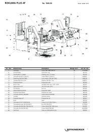
Zubehör und Ersatzteile / Accessories and spare parts<br />
Bestellen Sie Ihre Zubehör- und Ersatzteile bei Ihrem Fachhändler<br />
Order your accessories and spare parts from your specialist retailer<br />
oder bei unserer Hotline Service After Sales<br />
or from our Service After Sales hotline<br />
Tel. : +49 6195 / 99 52-14<br />
Fax : +49 6195 / 99 52-15<br />
Kunde / Anschrift<br />
Customer / address<br />
Kunden Nr. /<br />
customer no.<br />
Bestell Nr. /<br />
Order no.<br />
Ansprechpartner<br />
Contact person<br />
Tel.:<br />
Ihre Bestellung<br />
Your order<br />
Artikel Nr. /<br />
Article no.<br />
Menge /<br />
Quantity<br />
Bezeichnung /<br />
Description<br />
Stempel / Stamp<br />
Preis /<br />
Price<br />
Datum / Date Unterschrift / Signature<br />
21
NOTES<br />
22
NOTES<br />
23
NOTES<br />
24
NOTES<br />
25
ROTHENBERGER Worldwide<br />
Headquarter<br />
Germany<br />
Australia<br />
Austria<br />
Belgium<br />
Brazil<br />
Bulgaria<br />
Chile<br />
China<br />
Czech<br />
Republic<br />
Denmark<br />
France<br />
Greece<br />
Hungary<br />
India<br />
Ireland<br />
Italy<br />
ROTHENBERGER AG<br />
Industriestraße 7 • D-65779 Kelkheim/Germany<br />
Tel. + 49 61 95 / 800 - 1 • Fax + 49 61 95 / 7 44 22<br />
ROTHENBERGER Werkzeuge GmbH<br />
Industriestraße 7 • D-65779 Kelkheim/Germany<br />
Tel. + 49 61 95 / 800 - 1 • Fax + 49 61 95 / 7 44 22<br />
info@rothenberger.com • www.rothenberger.com<br />
ROTHENBERGER Produktion GmbH<br />
Lilienthalstraße 71 - 87 • D-37235 Hessisch-Lichtenau<br />
Tel.+ 49 56 02 / 93 94 - 0 • Fax + 49 56 02 / 93 94 36<br />
ROTHENBERGER Australia Pty. Ltd.<br />
Unit 12 • 5 Hudson Avenue • Castle Hill • N.S.W. 2154<br />
Tel. + 61 2 / 98 99 75 77 • Fax + 61 2 / 98 99 76 77<br />
rothenberger@rothenberger.com.au<br />
www.rothenberger.com.au<br />
ROTHENBERGER Werkzeuge- und Maschinen<br />
Handelsgesellschaft m.b.H.<br />
Gewerbeparkstraße 9 • A-5081 Anif near Salzburg<br />
Tel. + 43 62 46 / 7 20 91-45 • Fax + 43 62 46 / 7 20 91-15<br />
office@rothenberger.at • www.rothenberger.at<br />
ROTHENBERGER Benelux bvba<br />
Antwerpsesteenweg 59 • B-2630 Aartselaar<br />
Tel. + 32 3 / 8 77 22 77 • Fax + 32 3 / 8 77 03 94<br />
info@rothenberger.be • www.rothenberger.be<br />
ROTHENBERGER do Brasil Ltda.<br />
Rua marinho de Carvalho, No. 72 - Vila Marina<br />
09921-005 Diadema - Sao Paulo - Brazil<br />
Tel. + 55 11 / 40 44 47-48 • Fax + 55 11 / 40 44 50-51<br />
vendas@rothenberger.com.br • www.rothenberger.com.br<br />
ROTHENBERGER Bulgaria GmbH<br />
Boul. Sitniakovo 79 • BG-1111 Sofia<br />
Tel. + 35 92 / 9 46 14 59 • Fax + 35 92 / 9 46 12 05<br />
info@rothenberger.bg • www.rothenberger.bg<br />
ROTHENBERGER S.A., Oficinas en CHILE<br />
Merced# 32/ Oficina 63 - Santiago Centro<br />
Santiago - Chile<br />
Tel. + 56 9 / 2 99 68 79 • + 56 2 / 4 17 91 30<br />
Fax + 56 2 / 4 17 91 30 • ventas.chile@rothenberger.es<br />
ROTHENBERGER Pipe Tool (Shanghai) Co., Ltd.<br />
D-4, No.195 Qianpu Road,East New Area of Songjiang<br />
Industrial Zone, Shanghai, P.R.CHINA, Post Code: 201611<br />
Songjiang District, Shanghai, (201601) China<br />
Tel. + 86 21 67 60 20 57 • + 86 21 / 67 60 20 77<br />
Fax + 86 21 / 6760 2063 • sales@rothenberger.cn<br />
ROTHENBERGER CZ, náradí a stroje, spol. s.r.o.<br />
Lnárská 907 / 12 • CZ-104 00 Praha 10 - Uhríneves<br />
Tel. +42 02 / 71 73 01 83 • Fax +42 02 / 71 73 01 87<br />
info@rothenberger.cz • www.rothenberger.cz<br />
ROTHENBERGER Scandinavia A/S<br />
Fåborgvej 8 • DK-9220 Aalborg Øst<br />
Tel. + 45 98 / 15 75 66 • Fax + 45 98 / 15 68 23<br />
roscan@rothenberger.dk<br />
ROTHENBERGER France S.A.<br />
24, rue des Drapiers, BP 45033 • F-57071 Metz Cedex 3<br />
Tel. + 33 3 / 87 74 92 92 • Fax + 33 3 / 87 74 94 03<br />
info-fr@rothenberger.com<br />
ROTHENBERGER Hellas S.A.<br />
249 Syngrou Avenue • GR-171 22 Nea Smyrni, Athens<br />
Tel. + 30 210 / 94 07 302 • Fax + 30 210 / 94 07 322<br />
ro-he@otenet.gr<br />
ROTHENBERGER Hungary Kft.<br />
Gubacsi út 26 • H-1097 Budapest<br />
Tel. + 36 1 / 3 47 - 50 40 • Fax + 36 1 / 3 47 - 50 59<br />
mail@rothenberger.hu<br />
ROTHENBERGER India Private Limited<br />
B-1/D-5,Ground Floor<br />
Mohan Cooperative Industrial Estate,<br />
Mathura Road, New Delhi 110044<br />
Tel. + 91 11 / 51 69 90 70 • Fax + 91 11 / 51 69 90 60<br />
contactus@rothenbergerindia.com<br />
ROTHENBERGER Ireland Ltd.<br />
Bay N. 119, Shannon Industrial Estate<br />
IRL-Shannon, Co. Clare<br />
Tel. + 35 3 61 / 47 21 88 • Fax + 35 3 61 / 47 24 36<br />
rothenb@iol.ie<br />
ROTHENBERGER Italiana s.r.l.<br />
Via G. Reiss Romoli 17 • I-20019 Settimo Milanese<br />
Tel. + 39 02 / 33 50 12 12 • Fax + 39 02 / 33 50 0151<br />
rothenberger@rothenberger.it • www.rothenberger.it<br />
Mexico<br />
Netherlands<br />
Poland<br />
Portugal<br />
Singapore<br />
South Africa<br />
Spain<br />
Switzerland<br />
Turkey<br />
UAE<br />
UK<br />
USA<br />
Romania<br />
Russia<br />
ROTHENBERGER S.A. Sucursal México<br />
Bosques de Duraznos No. 69-1101<br />
Col. Bosques de las Lomas • México D.F. 11700<br />
Tel. + 52 55 / 55 96 - 84 98<br />
Fax + 52 55 / 26 34 - 25 55<br />
ROTHENBERGER Nederland bv<br />
Postbus 45 • NL-5120 AA Rijen<br />
Tel. + 31 1 61 / 29 35 79 • Fax + 31 1 61 / 29 39 08<br />
info@rothenberger.nl • www.rothenberger.nl<br />
ROTHENBERGER Polska Sp.z.o.o.<br />
ul. Cyklamenów 1 • PL-04-798 Warszawa<br />
Tel. + 48 22 / 6 12 77 01 • Fax + 48 22 / 6 12 72 95<br />
biuro@rothenberger.pl • www.rothenberger.pl<br />
SUPER-EGO TOOLS FERRAMENTAS, S.A.<br />
Apartado 62 - 2894-909 Alcochete - PORTUGAL<br />
Tel. + 351 91 / 930 64 00 • Fax + 351 21 / 234 03 94<br />
sul.pt@rothenberger.es<br />
ROTHENBERGER Asia Pte. Ltd.<br />
147 Thyrwhitt Road<br />
Singapore 207561<br />
Tel. + 65 / 6296 - 2031 • Fax + 65 / 6296 - 4031<br />
sales@rothenberger.com.sg • www.rothenberger.com.sg<br />
ROTHENBERGER-TOOLS SA (PTY) Ltd.<br />
P.O. Box 4360 • Edenvale 1610<br />
165 Vanderbijl Street, Meadowdale Germiston<br />
Gauteng (Johannesburg), South Africa<br />
Tel. + 27 11 / 3 72 96 33 • Fax + 27 11 / 3 72 96 32<br />
info@rothenberger-tools.co.za<br />
ROTHENBERGER S.A.<br />
Ctra. Durango-Elorrio, Km 2 • E-48220 Abadiano (Vizcaya)<br />
(P.O. Box) 117 • E-48200 Durango (Vizcaya)<br />
Tel. + 34 94 / 6 21 01 00 • Fax + 34 94 / 6 21 01 31<br />
export@rothenberger.es • www.rothenberger.es<br />
ROTHENBERGER (Schweiz) AG<br />
Herostr. 9 • CH-8048 Zürich<br />
Tel. +41 (0)44 435 30 30 • Fax 41 (0)44 401 06 08<br />
info@rothenberger-werkzeuge.ch<br />
ROTHENBERGER Tes. Alet ve Mak. San. Tic. Ltd. Sti<br />
Poyraz Sok. No: 20/3 - Detay Is Merkezi<br />
TR-34722 Kadiköy-Istanbul<br />
Tel. +90 / 216 449 24 85 pbx • Fax +90 / 216 449 24 87<br />
rothenberger@rothenberger.com.tr<br />
ROTHENBERGER Middle East FZCO<br />
PO Box 261190 • Jebel Ali Free Zone<br />
Dubai, United Arab Emirates<br />
Tel. +971 / 48 83 97 77 • Fax +971 / 48 83 97 57<br />
office@rothenberger.ae<br />
ROTHENBERGER UK Limited<br />
2, Kingsthorne Park, Henson Way,<br />
Kettering • GB-Northants NN16 8PX<br />
Tel. + 44 15 36 / 31 03 00 • Fax + 44 15 36 / 31 06 00<br />
info@rothenberger.co.uk<br />
ROTHENBERGER USA LLC<br />
4455 Boeing Drive, USA - Rockford, IL 61 109<br />
Tel. + 1 / 8 15 3 97 70 70 • Fax + 1 / 8 15 3 97 82 89<br />
www.rothenberger-usa.com<br />
ROTHENBERGER USA Inc.<br />
Western Regional Office • USA-955 Monterey Pass Road<br />
Monterey Park, CA 91754<br />
Tel. + 13 23 / 2 68 13 81 • Fax + 13 23 / 26 04 97<br />
ROTHENBERGER Agency<br />
RO-WALT Utilaje SRL<br />
Str. 1 Mai 2A<br />
RO/075100 Otopeni/Bucuresti, Ilfov<br />
Tel. +40 21 / 3 50 37 44 • +40 21 / 3 50 37 45<br />
Fax +40 21 / 3 50 37 46<br />
office.rothenberger-romania.ro<br />
OLMAX<br />
2-oy Werchnij Michajlowskij Projezd, d. 9,ET.4<br />
RUS-115419 Moscow<br />
Tel. + 7 / 09 57 92 59 44 Fax + 7 / 09 57 92 59 46<br />
olmax@olmax.ru • www.olmax.ru<br />
www.rothenberger.com<br />
9.0303/10.08/F&E