
Create successful ePaper yourself
Turn your PDF publications into a flip-book with our unique Google optimized e-Paper software.
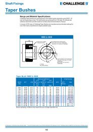
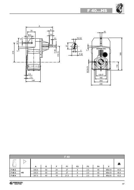
F <strong>40.</strong>..<strong>HS</strong>A79E1656.5F414F3F2 h92182797.57°F h6175.75VF h67°BONFIGLIOLI3893.57.5144M12x19130 f7165200116230F40A E F F1 F2 F3 F4 VF402335.5 50 24 27 8 2.5 45 M8x19 44.9F403 <strong>HS</strong>335.5 50 24 27 8 2.5 45 M8x19 46.4F404 357.5 40 19 21.5 6 2.5 35 M6x16 43.597
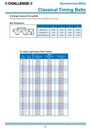
F 50...M93.565LFL20AD278211.5H105.5R22ACBONFIGLIOLI7°7°22°30’ 22°30’M12x191444794.58.5163180 f7215250280F50M_FDM_FAM_FDM_FAAC H L AD LF R AD R ADF 50 2/3 S1 M1S 138 424 399 108 72 462 75 103 132 124 108F 50 2/3 S1 M1L 138 424 423 108 73 484 76 103 132 124 108F 50 2/3 S2 M2S 156 433 452 119 73 522 76 129 143 134 119F 50 2/3 S3 M3S 195 452.5 495 142 77 591 85 160 155 160 142F 50 2/3 S3 M3L 195 452.5 527 142 85 618 92 160 155 160 142F 50 2/3 S4 M4S 258 484 597 193 104 706 118 226 193 217 193F 50 2/3 S4 M4L 258 484 635 193 119 744 137 226 193 217 193F 50 2/3 S4 M4LC 258 484 670 193 127 769 145 226 193 217 193F504 S1 M1S 138 424 470.5 108 74 533.5 77 103 132 124 108F504 S1 M1L 138 424 494.5 108 75 555.5 78 103 132 124 108F504 S2 M2S 156 433 523.5 119 79 593.5 83 129 143 134 119F504 S3 M3S 195 452.5 566.5 142 84 662.5 91 160 155 160 142F504 S3 M3L 195 452.5 598.5 142 91 689.5 98 160 155 160 14299
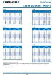
F 50...P(IEC)M2 H9154(P63)NN493.565PX20105.522BONFIGLIOLIM1N2M E72787°211.5N37°22°30’ 22°30’M12x19144479N14.58.5163180 f7215250280F50M M1 M2 N N1 N2 N3 N4 X PF 50 2/3 P63 11 12.8 4 140 115 95 — M8x19 4 268 65F 50 2/3 P71 14 16.3 5 160 130 110 — M8x16 4.5 268 65F 50 2/3 P80 19 21.8 6 200 165 130 — M10x12 4 287.5 67F 50 2/3 P90 24 27.3 8 200 165 130 — M10x12 4 287.5 67F 50 2/3 P100 28 31.3 8 250 215 180 — M12x16 4.5 297.5 71F 50 2/3 P112 28 31.3 8 250 215 180 — M12x16 4.5 297.5 71F 50 2/3 P132 38 41.3 10 300 265 230 16 14 5 334 74F 50 2/3 P160 42 45.3 12 350 300 250 23 18 5.5 384.5 78F 50 2/3 P180 48 51.8 14 350 300 250 23 18 5.5 384.5 78F504 P63 11 12.8 4 140 115 95 — M8x19 4 339.5 70F504 P71 14 16.3 5 160 130 110 — M8x16 4.5 339.5 70F504 P80 19 21.8 6 200 165 130 — M10x12 4 359 71F504 P90 24 27.3 8 200 165 130 — M10x12 4 359 71F 50 4 P100 28 31.3 8 250 215 180 — M12x16 4.5 369 75F 50 4 P112 28 31.3 8 250 215 180 — M12x16 4.5 369 75100
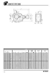
F 50...<strong>HS</strong>A6593.5EF42022F3F2 h927827105.57°F h6211.5VF h67°22°30’ 22°30’BONFIGLIOLIM12x191444794.58.5163180 f7215250280F50A E F F1 F2 F3 F4 VF502357.5 50 24 27 8 2.5 45 M8x19 65F503 <strong>HS</strong>357.5 50 24 27 8 2.5 45 M8x19 68F504 389.5 40 19 21.5 6 2.5 35 M6x16 70101
F 60...M11581LFL26ADAC325127R22BONFIGLIOLI7°7°267H22°30’ 22°30’M12x19142534410204180 f7215250307F60M_FDM_FAM_FDM_FAAC H L AD LF R AD R ADF603 S2 M2S 156 487 486.5 119 114 556.5 121 129 143 134 119F603 S3 M3S 195 506.5 529.5 142 114 625.5 122 160 155 160 142F603 S3 M3L 195 506.5 561.5 142 122 652.5 129 160 155 160 142F603 S4 M4S 258 538 631.5 193 141 739.5 155 226 193 217 193F603 S4 M4L 258 538 669.5 193 156 777.5 174 226 193 217 193F 60 3 S4 M4LC 258 538 704.5 193 164 802.5 182 226 193 217 193F603 S5 M5S 310 564 756 245 184 896 214 266 245 247 245F603 S5 M5L 310 564 800 245 200 940 230 266 245 247 245F604 S1 M1S 138 478 504 108 112 567 114 103 132 124 108F604 S1 M1L 138 478 528 108 113 589 116 103 132 124 108F604 S2 M2S 156 487 557 119 117 627 121 129 143 134 119F604 S3 M3S 195 506.5 600 142 122 696 129 160 155 160 142F604 S3 M3L 195 506.5 632 142 129 723 136 160 155 160 142F604 S4 M4L 258 538 740 193 156 849 174 226 193 217 193F 60 4 S4 M4LC 258 538 775 193 164 874 182 226 193 217 193103
F 60...P(IEC)M2 H9154(P63)NN42211581PX26127BONFIGLIOLIM1N2M E73257°267N37°22°30’ 22°30’M12x19142534N1410204180 f7215250307F60M M1 M2 N N1 N2 N3 N4 X PF603 P63 11 12.8 4 140 115 95 — M8x19 4 302.5 103F603 P71 14 16.3 5 160 130 110 — M8x16 4.5 302.5 103F603 P80 19 21.8 6 200 165 130 — M10x12 4 322 104F603 P90 24 27.3 8 200 165 130 — M10x12 4 322 104F 60 3 P100 28 31.3 8 250 215 180 — M12x16 4.5 331 108F 60 3 P112 28 31.3 8 250 215 180 — M12x16 4.5 331 108F 60 3 P132 38 41.3 10 300 265 230 16 14 5 367.5 111F 60 3 P160 42 45.3 12 350 300 250 23 18 5.5 419 116F 60 3 P180 48 51.8 14 350 300 250 23 18 5.5 419 116F604 P63 11 12.8 4 140 115 95 — M8x19 4 373 108F604 P71 14 16.3 5 160 130 110 — M8x16 4.5 373 108F604 P80 19 21.8 6 200 165 130 — M10x12 4 392.5 110F604 P90 24 27.3 8 200 165 130 — M10x12 4 392.5 110F 60 4 P100 28 31.3 8 250 215 180 — M12x16 4.5 402.5 114F 60 4 P112 28 31.3 8 250 215 180 — M12x16 4.5 402.5 114104
F 60...<strong>HS</strong>A81115EF42622F3F2 h9325311277°F h6267VF h67°22°30’ 22°30’BONFIGLIOLIM12x19142534410204180 f7215250307F60A E F F1 F2 F3 F4 VF603419 60 28 31 8 5.0 50 M10x22 108<strong>HS</strong>F604 462.5 50 24 27 8 2.5 45 M8x19 105105
F60H60STANDARD18F 60...H64.460701760 G7401822044014.5M121026155 133 6235NmF 60...S16567 G765 H716512018 h9F 60...R64M1660 h65 205 184 13F 60...F...400300 f7350250 f7300230 f7454545350183001826514C B A106
F 70...M14499.5LLFAD303701507°285 2680AC306 RH7°22°30’ 22°30’BONFIGLIOLIM14x22158608M16x3045.5 190410261205 f7235270345F70M_FDM_FAM_FDM_FAAC H L AD LF R AD R ADF703 S2 M2S 156 542 552 119 173 622 177 129 143 134 119F703 S3 M3S 195 561.5 595 142 178 691 186 160 155 160 142F703 S3 M3L 195 561.5 627 142 186 718 193 160 155 160 142F703 S4 M4S 258 593 697 193 205 806 219 226 193 217 193F703 S4 M4L 258 593 735 193 220 844 238 226 193 217 193F 70 3 S4 M4LC 258 593 770 193 228 869 246 226 193 217 193F703 S5 M5S 310 619 821.5 245 248 961.5 278 266 245 247 245F703 S5 M5L 310 619 865.5 245 264 1005.5 294 266 245 247 245F704 S1 M1S 138 533 550 108 171 613 174 103 132 124 108F704 S1 M1L 138 533 574 108 173 635 176 103 132 124 108F704 S2 M2S 156 542 603 119 177 673 180 129 143 134 119F704 S3 M3S 195 561.5 646 142 181 742 189 160 155 160 142F704 S3 M3L 195 561.5 678 142 189 769 196 160 155 160 142F704 S4 M4S 258 593 748 193 208 857 222 226 193 217 193F704 S4 M4L 258 593 786 193 223 895 241 226 193 217 193F 70 4 S4 M4LC 258 593 821 193 231 920 249 226 193 217 193107
F 70...P(IEC)154(P63)PN14430M2 H9N499.5X15026M1BONFIGLIOLI7°7°N2N1M E737028580306N322°30’ 22°30’M14x22158608M16x3045.5190410261205 f7235270345F70M M1 M2 N N1 N2 N3 N4 X PF703 P80 19 21.8 6 200 165 130 — M10x12 4 387.5 167F703 P90 24 27.3 8 200 165 130 — M10x12 4 387.5 167F 70 3 P100 28 31.3 8 250 215 180 — M12x16 4.5 397.5 171F 70 3 P112 28 31.3 8 250 215 180 — M12x16 4.5 397.5 171F 70 3 P132 38 41.3 10 300 265 230 16 14 5 434 173F 70 3 P160 42 45.3 12 350 300 250 23 18 6 489.5 185F 70 3 P180 48 51.8 14 350 300 250 23 18 6 489.5 185F 70 3 P200 55 59.3 16 400 350 300 — M16x25 7 514.5 206F704 P63 11 12.8 4 140 115 95 — M8x19 4 419 168F704 P71 14 16.3 5 160 130 110 — M8x16 4.5 419 168F704 P80 19 21.8 6 200 165 130 — M10x12 4 438.5 170F704 P90 24 27.3 8 200 165 130 — M10x12 4 438.5 170F 70 4 P100 28 31.3 8 250 215 180 — M12x16 4.5 446.5 174F 70 4 P112 28 31.3 8 250 215 180 — M12x16 4.5 446.5 174F 70 4 P132 38 41.3 10 300 265 230 16 14 5 482 176108
F 70...<strong>HS</strong>A99.5144EF43026F3F2 h9370451507°28580F h6306VF h67°22°30’ 22°30’BONFIGLIOLIM14x22158608M16x3045.5 190410261205 f7235270345F70A E F F1 F2 F3 F4 VF703572 110 42 45 12 10 90 M12x28 186<strong>HS</strong>F704 508.5 50 24 27 8 2.5 45 M8x19 174109
F 80...M122.5174.5LLFAD364307°176330 2690AC355 RH7°22°30’ 22°30’BONFIGLIOLIM16x28183714M20x3551 230410309230 f7265300411F80M_FDM_FAM_FDM_FAAC H L AD LF R AD R ADF803 S4 M4S 258 667 755 193 292 864 306 226 193 217 193F803 S4 M4L 258 667 793 193 307 902 325 226 193 217 193F 80 3 S4 M4LC 258 667 828 193 315 927 333 226 193 217 193F803 S5 M5S 310 693 879.5 245 335 1019.5 365 266 245 247 245F803 S5 M5L 310 693 923.5 245 351 1063.5 381 266 245 247 245F804 S1 M1S 138 607 620 108 261 683 263 103 132 124 108F804 S1 M1L 138 607 644 108 262 705 265 103 132 124 108F804 S2 M2S 156 616 673 119 266 743 269 129 143 134 119F804 S3 M3S 195 635.5 716 142 271 812 278 160 155 160 142F804 S3 M3L 195 635.5 748 142 278 839 285 160 155 160 142F804 S4 M4S 258 667 818 193 297 927 311 226 193 217 193F804 S4 M4L 258 667 856 193 312 965 330 226 193 217 193F 80 4 S4 M4LC 258 667 891 193 320 990 338 226 193 217 193111
F 80...P(IEC)M2 H9154(P63)NN4122.5174.5PX36176M126BONFIGLIOLI7°N2N1M E743033090355N37°22°30’22°30’M16x28183714M20x3551230410309230 f7265300411F80M M1 M2 N N1 N2 N3 N4 X PF803 P80 19 21.8 6 200 165 130 — M10x12 4 445.5 255F803 P90 24 27.3 8 200 165 130 — M10x12 4 445.5 255F 80 3 P100 28 31.3 8 250 215 180 — M12x16 4.5 455.5 259F 80 3 P112 28 31.3 8 250 215 180 — M12x16 4.5 455.5 259F 80 3 P132 38 41.3 10 300 265 230 16 14 5 492 261F 80 3 P160 42 45.3 12 350 300 250 23 18 6 547.5 276F 80 3 P180 48 51.8 14 350 300 250 23 18 6 547.5 276F 80 3 P200 55 59.3 16 400 350 300 — M16x25 7 572.5 298F 80 3 P225 60 64.4 18 450 400 350 25 18 6 618 298F804 P63 11 12.8 4 140 115 95 — M8x19 4 489 258F804 P71 14 16.3 5 160 130 110 — M8x16 4.5 489 258F804 P80 19 21.8 6 200 165 130 — M10x12 4 508.5 260F804 P90 24 27.3 8 200 165 130 — M10x12 4 508.5 260F 80 4 P100 28 31.3 8 250 215 180 — M12x16 4.5 518.5 264F 80 4 P112 28 31.3 8 250 215 180 — M12x16 4.5 518.5 264F 80 4 P132 38 41.3 10 300 265 230 16 M12x16 5 552 266112
F 80...<strong>HS</strong>A122.5174.5EF43626F3F2 h9430451767°33090F h6355VF h67°22°30’22°30’BONFIGLIOLIM16x28183714M20x3551 230410309230 f7265300411F80A E F F1 F2 F3 F4 VF803630 110 42 45 12 10 90 M12x28 273<strong>HS</strong>F804 575.5 50 24 27 8 2.5 45 M8x19 263113
F80H90STANDARD25F 80...H95.490952290 G7802743098018.5M161037890 177 100 69 NmF 80...S92 G790 H719524017025 h9F 80...R95M2090 h65 245 22F 80...F...550450 f7450350 f770705001840018BA114
F 90...M132.5201LLFAD405152117°400 32100AC433 RH7°22°30’ 22°30’BONFIGLIOLIM20x33226862M30x5061.5 270511367.5250 f7300350495F90M_FDM_FAM_FDM_FAAC H L AD LF R AD R ADF903 S3 M3S 195 756 728 142 453 824 460 160 155 160 142F903 S3 M3L 195 756 760 142 460 851 467 160 155 160 142F903 S4 M4S 258 787.5 830 193 479 939 493 226 193 217 193F903 S4 M4L 258 787.5 868 193 494 977 512 226 193 217 193F903 S5 M5L 310 813.5 998.5 245 538 1138.5 568 266 245 247 245F904 S2 M2S 156 736.5 768 119 456 838 460 129 143 134 119F904 S3 M3S 195 756 811 142 460 907 468 160 155 160 142F904 S3 M3L 195 756 843 142 468 934 475 160 155 160 142F904 S4 M4S 258 787.5 913 193 487 1022 501 226 193 217 193F904 S4 M4L 258 787.5 951 193 502 1060 520 226 193 217 193F 90 4 S4 M4LC 258 787.5 986 193 510 1085 528 226 193 217 193115
F 90...P(IEC)M2 H9154(P63)NN4201132.5PX40211M132BONFIGLIOLI7°N2N1M E7515400100433N37°22°30’22°30’M20x33226862M30x5061.5270511367.5250 f7300350495F90M M1 M2 N N1 N2 N3 N4 X PF903 P80 19 21.8 6 200 165 130 — M10x12 4 520.5 442F903 P90 24 27.3 8 200 165 130 — M10x12 4 520.5 442F 90 3 P100 28 31.3 8 250 215 180 — M12x16 4.5 530.5 446F 90 3 P112 28 31.3 8 250 215 180 — M12x16 4.5 530.5 446F 90 3 P132 38 41.3 10 300 265 230 16 14 5 567 449F 90 3 P160 42 45.3 12 350 300 250 23 18 6 622.5 463F 90 3 P180 48 51.8 14 350 300 250 23 18 6 622.5 463F 90 3 P200 55 59.3 16 400 350 300 — M16x25 7 647.5 485F 90 3 P225 60 64.4 18 450 400 350 30 18 6 693 485F 90 3 P250 65 69.4 18 550 500 450 30 18 6 723 507F904 P63 11 12.8 4 140 115 95 — M8x19 4 584 448F904 P71 14 16.3 5 160 130 110 — M8x16 4.5 584 448F904 P80 19 21.8 6 200 165 130 — M10x12 4 603.5 450F904 P90 24 27.3 8 200 165 130 — M10x12 4 603.5 450F 90 4 P100 28 31.3 8 250 215 180 — M12x16 4.5 613.5 454F 90 4 P112 28 31.3 8 250 215 180 — M12x16 4.5 613.5 454F 90 4 P132 38 41.3 10 300 265 230 16 14 5 650 455F 90 4 P160 42 45.3 12 350 300 250 23 18 5.5 700.5 461F 90 4 P180 48 51.8 14 350 300 250 23 18 5.5 700.5 461116
F 90...<strong>HS</strong>A132.5201EF44032F3F2 h9515642117°400100F h6433VF h67°22°30’22°30’BONFIGLIOLIM20x33226862M30x5061.5 270511367.5250 f7300350495F90A E F F1 F2 F3 F4 VF903806.5 140 60 64 18 10 120 M16x36 485<strong>HS</strong>F904 673.5 50 24 27 8 2.5 45 M8x19 452117
F90H100STANDARD28F 90...H106.410011026100G790335.5367.59021M1611441.5100 221.5 110 69NmF 90...S102 G7100 H722528421028 h9F 90...R106M24100 h65 24F 90...F...550450 f77450018A118
31 - ACCESSORI31 - ACCESSORIES31 - ZUBEHÖR31 - ACCESSOIRESKit antivibranteI riduttori serie F possono esserecorredati , a richiesta, di unkit antivibrante che comprende icomponenti necessari per il fissaggiopendolare (braccio di reazioneescluso).Le dimensioni sono riportatenella tabella (B20).Anti-vibration kitThe gearboxes of the F seriesare supplied with an anti-vibrationkit at customer request.The kit includes all componentsrequired for shaft mounting(torque arm is out of scope).Dimensions are shown in thetable (B20).SchwingungsdämpfungDie Getriebe der Serie F könnenauf Anfrage mit einem Satsan Schwingungsdämpfern gelifertwerden. Dieser Satz enthältdie für die Aufsteckbefestigungerforderlichen Komponenten(ausgenommen Achsstrebe).Die Abmessungen sind aus derTabelle (B20) ersichtlich.Kit de fixation pour bras deréaction avec butée en caoutchoucantivibrationsLes réducteurs de la série Fpeuvent être équipés, sur demande;d’un kit antivibration, incluantles composants nécessairesà la fixation pendulaire(bras de réaction exclu).Les dimensions sont indiquéesdans le tableau (B20).(B20)F3 F4 F6 F7 (max.) HD L1T L2T D1T D2T M ftF10 140 20 55 10 12.3 15 5 11 30 M10x80 1.5F20 160 20 55 10 12.3 15 5 11 30 M10x80 1.5F30 170 20 65 20 14.8 20 5 12.5 40 M12x100 1.5F40 218 16 61 24 14.8 20 5 12.5 40 M12x100 2.3F50 278 20 90 47 23 30 10 21 60 M20x160 3.0F60 325 26 96 41 23 30 10 21 60 M20x160 4.0F70 370 30 122 50 28 40 12 25 80 M24x200 4.0F80 430 36 128 44 28 40 12 25 80 M24x200 6.0F90 515 40 175 40 33.2 60 15 32 100 M30x260 9.0f t=variazione dimensionale del tamponedi gomma antivibrante.f t=shortening of the rubber bufferunder rated torque transmission.f t=Stauchung des Gummipuffersunter Nennlast.f t=variation dimensionnelle du tamponde caoutchouc antivibrante.119
FlangeAi riduttori può essere applicatauna flangia in uscita che puòassumere varie configurazioni(A,B,C) in base alle dimensioni.È un accessorio fornito a richiestae le caratteristiche dei tretipi di flange applicabili sono riportatenella tabella (B21).FlangesAn output flange can be appliedto gearboxes. Different configurations(A,B,C) according to dimensionsare available.This is an optional accessory.The characteristics of the threeapplicable flanges are shown inthe table (B21).FlanscheAuf dem Ausgang der Untersetzungsgetriebekann ein Flanschmontiert werden, der je nachAbmessungen verschiedeneBaugrößen (A,B,C) haben kann.Es handelt sich dabei um einZubehörteil, das auf Verlangengeliefert wird, die Abmessungender drei Flanschtypen werden inder Tabelle B21 angegeben.BridesLes réducteurs peuvent être dotésà la sortie d’une bride, quipeut présenter différentes configurations(A,B.C) selon les dimensions.Cet accessoire est fourni surdemande. Les caractéristiquesde trois types de bride sont indiquéesdans le tableau (B21).(B21)F10F20D1 D2 D3 G I1 X1 Y1FA 110 130 160 9 3 10 31.5FB 130 165 200 11 3.5 11 31.5FC 180 215 250 14 4 13 31.5FA 110 130 160 9 3 10 36FB 130 165 200 11 3.5 11 36FC 180 215 250 14 4 13 36F30FA 180 215 250 14 4 13 33FB 230 265 300 14 4 16 33FA 180 215 250 14 4 13 32.5F40FB 230 265 300 14 4 16 32.5FC 250 300 350 18 5 18 32.5FA 230 265 300 14 4 13 46.5F50FB 250 300 350 18 5 18 46.5FC 300 350 400 18 5 20 46.5FA 230 265 300 14 4 13 45F60FB 250 300 350 18 5 18 45FC 300 350 400 18 5 20 45F70FA 350 400 450 18 5 22 67.5FB 450 500 550 18 5 24 67.5F80FA 350 400 450 18 5 22 70FB 450 500 550 18 5 24 70F90 FA 450 500 550 18 5 24 74120
Albero lento sporgenteLa tabella (B22) riporta le dimensionidegli alberi lenti sporgentiforniti, a richiesta, comeaccessori con i riduttori serie F.Output shaft extensionThe table (B22) shows the dimensionsof the output shaft extensionswhich are supplied, onrequest, as accessories to the Fseries gearboxes.HerausragendeAufsteckabtriebswelleIn der Tabelle (B22) werden dieAbmessungen der Aufsteckabtriebswelleangegeben, die aufVerlangen als Zubehörteile mitden Untersetzungsgetriebender Serie F geliefert werdenArbre lent saillantLe tableau (B22) indique les dimensionsdes arbres lents saillantsfournis, sur demande.comme accessoires avec les réducteursde la série F.(B22)B h6 B1 B2 C L1 L2 UF10 25 28 8 45 76.5 87.5 M8F20 30 33 8 60 96 100 M10F30 35 38 10 60 93 104 M10F40 40 43 12 80 112.5 118.5 M12F50 50 53.5 14 100 146.5 139.5 M16F60 60 64 18 120 165 180 M16F70 80 85 22 130 197.5 229.5 M20F80 90 95 25 170 240 272 M20F90 100 106 28 210 284 333 M24121
32 - PERNO MACCHINA32 - CUSTOMER' SHAFT 32 - MASCHINAC<strong>HS</strong>E 32 - ARBRE MACHINENel realizzare l'albero condottoche si accoppierà con il riduttoreconsigliamo di utilizzare acciaiodi buona qualità e di realizzarele dimensioni come suggeritonello schema seguente.Suggeriamo inoltre di completareil montaggio con un dispositivoche realizza il bloccaggio assialedell'albero (non illustrato).Il numero e la dimensionedel/dei relativi fori filettatiall'estremità dell'albero sarannodeterminati dalle diverse esigenzeapplicative.Pivot of driven equipmentshould be made from high gradealloy steel. Table below showsrecommended dimensions forthe Customer to consider whendesigning mating shaft.A device retaining the shaft axiallyis also recommended (notshown).The number and size of relativetapped holes at shaft end dependon application requirements.Für die mit dem Getriebe verbundeneAntriebswelle, wirdempfohlen, hochwertigen Stahlzu verwenden und die im folgendenSchema enthaltenen Abmessungenzu beachten. Eswird außerdem empfohlen, dieMontage mit Hilfe einer Vorrichtung,die die Welle axial blockiert(nicht abgebildet), vorzunehmen.Die Anzahl und die Abmessungdes/der Gewindebohrungen anden Wellenenden werden denEinsatzbedingungen gemäß festgelegt.Pour la réalisation de l’arbremené d’accouplement avec le réducteur,nous conseillons d’utiliserde l’acier de bonne qualité etde respecter les dimensions indiquéessur le schéma suivant.Il est recommandé de compléterle montage par un dispositif deblocage axial de l’arbre (non illustré)Le nombre et les dimensionsde(s) l’orifice (s) fileté (s) correspondant(s)à l’extrémité de l’arbresont déterminés par les différentesexigences d’application.HF10F20F30F40F50F60F70F80F90A1 A2 A3 B B1 B2 C D E F G R SUNI 6604 35 30 h7 29 79 15.5 48 20 2 2 33 8 h9 0.5 1.5 8x7x20 A 30 25 h7 24 79 15.5 48 20 2 2 28 8 h9 0.5 1.5 8x7x20 A 42 35 h7 34 99 18 63 22 2 2 38 10 h9 0.5 1.5 10x8x22 A 35 30 h7 29 99 18 63 22 2 2 33 8 h9 0.5 1.5 8x7x22 A 47 40 h7 39 104 28 48 30 2 2 43 12 h9 0.5 1.5 12x8x30 A 42 35 h7 34 104 28 48 30 2 2 38 10 h9 0.5 1.5 10x8x30 A 52 45 h7 44 118 27.5 63 45 2.5 2.5 49.5 14 h9 1 2.0 14x9x45 A 47 40 h7 39 118 27.5 63 45 2.5 2.5 43 12 h9 1 2.0 12x8x45 A 63 55 h7 54 139 33 73 50 2.5 2.5 59 16 h9 1 2.0 16x10x50 A 57 50 h7 49 139 33 73 50 2.5 2.5 53.5 14 h9 1 2.0 14x9x50 A 78 70 h7 69 180 38 104 70 2.5 2.5 74.5 20 h9 1 2.0 20x12x70 A 68 60 h7 59 180 38 104 70 2.5 2.5 64 18 h9 1 2.0 18x11x70 A 89 80 h7 79 229 58 113 75 3 3 85 22 h9 2.5 2.5 22x14x75 A 78 70 h7 69 229 58 113 75 3 3 74.5 20 h9 2.5 2.5 20x12x75 A 99 90 h7 89 272 78 116 100 3 3 95 25 h9 2.5 2.5 25x14x100 A 89 80 h7 79 272 78 116 100 3 3 85 22 h9 2.5 2.5 22x14x100 A 111 100 h7 99 333 87.5 158 110 3 3 106 28 h9 2.5 2.5 28x16x110 A 99 90 h7 89 333 87.5 158 110 3 3 95 25 h9 2.5 2.5 25x14x110 ASA1 A2 A3 A4 B B1 B2 R SF10 36 27 h7 24 25 h6 138 34 70 0.5 1.5F20 42 32 h7 29 30 h6 160 38 84 0.5 1.5F30 50 38 h7 35 36 h6 155 40 73 1 2F40 58 44 h7 41 42 h6 177 46.5 82 1 2F50 68 54 h7 51 52 g6 201 48 91 1 2F60 84 67 h7 64 65 g6 248 53 133 1.5 2F70 104 82 h7 79 80 g6 308 78 140 2.5 2.5F80 114 92 h7 89 90 g6 365 88 177 2.5 2.5F90 126 102 h7 99 100 g6 429.5 98 221.5 2.5 2.5122
MOTORI ELETTRICI ELECTRIC MOTORS ELEKTROMOTOREN MOTEURSELECTRIQUESM1 - SIMBOLOGIA EUNITÀ DI MISURAM1 - SYMBOLS AND UNITSOF MEASUREMENTM1 - SYMBOLE UNDMAßEINHEITENM1 - SYMBOLES ET UNITESDE MESURESimb.Symb.U.m.EinheitDescrizione Description Beschreibung Descriptioncos – Fattore di potenza Power factor Leistungsfaktor Facteur de puissance – Rendimento Efficiency Wirkungsgrad Rendementf m – Fattore correttivodella potenzaPower adjusting factor Leistungskorrekturfaktor Facteur de correction de lapuissanceI – Rapporto di intermittenza Cyclic duration factor Relative Einschaltdauer Rapport d’intermittenceI N [A] Corrente nominale Rated current Nennstrom Courant nominalI S [A] Corrente di spunto Locked rotor current Kurzschlußstrom Courant de démarrageJ C [Kgm 2 ] Momento di inerziadel caricoLoad moment of inertiaMassenträgheitsmomentder externen MassenMoment d’inertie de la chargeJ M [Kgm 2 ] Momento di inerzia motore Moment of inertia Trägheitsmoment Moment d’inertie du moteurK c – Fattore di coppia Torque factor Drehmomentfaktor Facteur de coupleK d – Fattore di carico Load factor Lastfaktor Facteur de chargeK J – Fattore di inerzia Inertia factor Trägheitsfaktor Facteur d’inertieM A [Nm] Coppia accelerante media Mean breakaway torque Losbrechmoment Couple d’accélération moyenM B [Nm] Coppia frenante Brake torque Bremsemoment Couple du freinM N [Nm] Coppia nominale Rated torque Nennmoment Couple nominalM L [Nm] Coppia resistente media Counter-torque during LastmomentCouple résistant moyenaccelerationM S [Nm] Coppia di spunto Starting torque Startmoment Couple de démarragen [min -1 ] Velocità nominale Rated speed Nenndrehzahl Vitesse nominaleP B [W] Potenza assorbitadal freno a 20°CPower drawn by thebrake at 20°CLeistungsaufnahmeder Bremse bei 20°CPuissance absorbée par lefrein à 20°CP n [kW] Potenza nominale Motor rated power Nennleistung Puissance nominaleP r [kW] Potenza richiesta Required power Benötigte Leistung Puissance nécessairet 1 [ms] Ritardo di sblocco del frenocon alimentatore a semiondat 1s [ms] Tempo di sblocco del frenocon alimentatore a controlloelettronicot 2 [ms] Ritardo di frenatura con disgiunzionelato c.a.t 2c [ms] Ritardo di frenatura con disgiunzionecircuitoc.a. e c.c.Brake response time withone-way rectifierBrake response time withelectronic-controlled rectifierBrake reaction time witha.c. disconnectBrake reaction time witha.c. and d.c. disconnectAnsprechzeit Bremsemit Einweg-GleichrichterAnsprechzeit Bremse mitelektronisch gesteuertemGleichrichterEinfallzeit Bremse bei Unterbrechungder StromversorgungWSEinfallzeit Bremse bei Unterbrechungder StromversorgungWS und GSTemps de déblocage du freinavec alimentation à demi-ondeTemps de déblocage du freinavec alimentation à contrôleélectroniqueRetard de freinage aveccoupure coté c.a.Retard de freinage aveccoupure coté c.a. et c.c.t a [°C] Temperatura ambiente Ambient temperature Umgebungstemperatur Température ambiantet f [min] Tempo di funzionamentoa carico costanteWork time at constant loadBetriebsdauer unterNennbelastungTemps de fonctionnement àcharge constantet r [min] Tempo di riposo Rest time Aussetzzeit Temps de reposW [J] Lavoro di frenatura accumulatotra due regolazioni del traferroW max [J] Energia massima per singolafrenaturaZ [1/h] N° di avviamenti ammissibili,a caricoZ 0 [1/h] N° di avviamenti ammissibilia vuoto (I = 50%)Braking work betweenservice intervalMaximum brake work foreach brakingPermissible startingfrequency, loadedMax. permissible unloadedstarting frequency (I = 50%)Bremsenergie zwichen zweiEinstellungenMax. Bremsarbeit proBremsvorgangSchalthäufigkeit NennbetriebMax. Schalthäufigkeit imLeerlauf (relative EinschaltdauerI = 50%)Energie de freinageaccumulée entre deuxréglages de l'entreferEnergie maxi par freinageNombre de démarrages admissiblesen chargeNombre de démarrages admissibleà vide (I = 50%)123
M2 - CARATTERISTICHEGENERALIM2 - GENERALCHARACTERISTICSM2 - ALLGEMEINEEIGENSCHAFTENM2 - CARACTERISTIQUESGENERALESProgramma di produzioneProduction rangeProduktprogrammProgramme de productionI motori elettrici asincroni trifasedel programma di produzionedella BONFIGLIOLI RIDUT-TORI sono previsti nelle formecostruttive base IMB5, IMB14 eloro derivate con le seguenti polarità:2, 4, 6, 2/4, 2/6, 2/8, 2/12.Nel presente catalogo sono evidenziateinoltre, le caratteristichetecniche dei motori in versioneintegrata, tipo M.The asynchronous three-phaseelectric motors of BONFIGLIOLIRIDUTTORI’s production, areavailable in basic designs IMB5and IMB14 and derived versions,with the following polarities:2, 4, 6, 2/4, 2/6, 2/8, 2/12.The technical characteristics ofcompact motors, M type, arealso supplied in this manual.Die Dreiphasen-Asynchronmotorenaus dem Produktprogrammvon BONFIGLIOLI RIDUTTORIgibt es in den GrundbauformenIMB5, IMB14 und deren Ableitungenmit folgenden Polzahlen: 2,4, 6, 2/4, 2/6, 2/8 und 2/12.Im vorliegenden Katalog sind außerdemdie technischen Eigenschaftender Motoren in Kompaktausführunghervogehoben.Les moteurs électriques asynchronestriphasés du programmede production de BONFIGLIOLIRIDUTTORI sont prévus dans lesformes de construction de baseIMB5, IMB14 et leur dérivés avecles polarités suivantes: 2, 4, 6,2/4, 2/6, 2/8, 2/12.Dans le présent catalogue sontégalement mises en évidenceles caractéristiques techniquesdes moteurs en version compacte,type M.NormativeStandardsNormenRéglementationsI motori descritti in questo catalogosono costruiti in accordo alleNorme ed unificazioni applicabilievidenziate nella tabella seguente.The motors described in this catalogueare manufactured to theapplicable standards shown inthe following table.Die in diesem Katalog beschriebenenMotoren sind in Übereinstimmungmit den in der folgendenTabelle angegebenen einschlägigenNormen und Vereinheitlichungsrichtlinienkonstruiertworden.Les moteurs décrits dans ce cataloguesont construits en accordavec les Normes et standardisationsapplicables mises en évidencedans le tableau ci-dessous.(A26)Titolo / Title / Titel / Titre CEI IECPrescrizioni generali per macchine elettriche rotantiGeneral requirements for rotating electrical machinesAllgemeine Vorschriften für umlaufende elektrische MaschinenPrescriptions générales pour machines électriques tournantesMarcatura dei terminali e senso di rotazione per macchine elettriche rotantiTerminal markings and direction of rotation of rotating machinesKennzeichnung der Anschlußklemmen und Drehrichtung von umlaufenden elektrischen MaschinenDéfinitions des bornes et sens de rotation pour machines électriques tournantesMetodi di raffreddamento delle macchine elettricheMethods of cooling for electrical machinesVerfahren zur Kühlung von elektrischen MaschinenMéthodes de refroidissement des machines électriquesDimensioni e potenze nominali per macchine elettriche rotantiDimensions and output ratings for rotating electrical machinesAuslegung der Nennleistung von umlaufenden elektrischen MaschinenDimensions, puissances nominales pour machines électriques tournantesClassificazione dei gradi di protezione delle macchine elettriche rotantiClassification of degree of protection provided by enclosures for rotating machinesKlassifizierung der Schutzart von umlaufenden elektrischen MaschinenClassification des degrés de protection des machines électriques tournantesLimiti di rumorositàNoise limitsGeräuschgrenzwerteLimites de bruitSigle di designazione delle forme costruttive e dei tipi di installazioneClassification of type of construction and mounting arrangementsAbkürzungen zur Kennzeichnung der Bauform und der EinbaulagenSigles de dénomination des formes de construction et des types d’installationTensione nominale per i sistemi di distribuzione pubblica dell’energia elettrica a bassa tensioneRated voltage for low voltage mains powerNennspannung für öffentliche NS-StromverteilungssystemeTension nominale pour les systèmes de distribution publique de l’énergie électrique en basse tensionGrado di vibrazione delle macchine elettricheVibration level of electric machinesSchwingstärke bei elektrischen MaschinenDegré de vibration des machines électriquesCEI EN 60034-1 IEC 60034-1CEI 2-8 IEC 60034-8CEI EN 60034-6 IEC 60034-6EN 50347 IEC 60072CEI EN 60034-5 IEC 60034-5CEI EN 60034-9 IEC 60034-9CEI EN 60034-7 IEC 60034-7CEI 8-6 IEC 60038CEI EN 60034-14 IEC 60034-14124
I motori corrispondono inoltrealle Norme straniere adeguatealle IEC 60034-1 e qui riportate.(A27)The motors also comply with foreignstandards adapted to IEC60034-1 as shown here below.Die Motoren entsprechen außerdemden an die IEC-Norm60034-1 angepaßten ausländischenNormen, die in der folgendenTabelle genannt werden.En outre, les moteurs correspondentaux Normes étrangèresadaptées aux IEC 60034-1 indiquéesdans le tableau ci-dessous.DIN VDE 0530 Germania Germany Deutschland AllemagneBS5000 / BS4999 Gran Bretagna Great Britain Großbritannien Grande BretagneAS 1359 Australia Australia Australien AustralieNBNC 51 - 101 Belgio Belgium Belgien BelgiqueNEK - IEC 34 Norvegia Norway Norwegen NorvègeNF C 51 Francia France Frankreich FranceOEVE M 10 Austria Austria Österreich AutricheSEV 3009 Svizzera Switzerland Schweiz SuisseNEN 3173 Paesi Bassi Netherlands Niederlande Pays BasSS 426 01 01 Svezia Sweden Schweden SuèdeCUSMOTORI PER USA E CANADAMOTORS FOR USAAND CANADAMOTOREN FÜR DIE USAUND KANADAMOTEURS POURETATS-UNIS ET CANADAI motori BN ed M sono disponibiliin esecuzione NEMA Design C(per le caratteristiche elettriche),certificata in conformità alle normeCSA (Canadian Standard)C22.2 N° 100 e UL (UnderwritersLaboratory) UL 1004 con targhettariportante il marchiocCSAus (tensione 600V), specificarein questo caso l'opzioneCUS.Le tensioni delle reti di distribuzioneamericane e le corrispondentitensioni nominali da specificareper il motore sono indicatenella tabella seguente:(A28)Frequenza / FrequencyFrequenz / Fréquence60 HzBN and M motors are availablein NEMA Design C configuration(concerning electrical characteristics),certified to CSA (Canadianstandard) C22.2 No. 100and UL (Underwriters Laboratory)UL 1004. Name plate includesthe cCSAus mark (voltage 600V), in this case,please specify CUS option.US power mains voltages andthe corresponding rated voltagesto be specified for the motorare indicated in the followingtable:Tensione di rete / Mains voltageNetzspannung / Tension de réseauDie BN/M-Motoren sind in derAusführung NEMA, Design C(aufgrund der elektrischen Eigenschaften),den Normen CSA(Canadian Standard) C22.2 Nr100 und UL (Underwriters Laboratory)UL 1004 gemäß zertifiziert,mit einem Typenschild mitcCSAus Zeichen (Spannung 600V), in diesem Fall muss dieOption CUS angegeben werden.Die Spannungen der amerikanischenVerteilernetze und dieentsprechenden tens-Nennspannungen,die bei den Motorenangegeben werden müssen,können der folgenden Tabelleentnommen werden:V mot208 V 200 V240 V 230 V480 V 460 V600 V 575 VLes moteurs BN et M sont disponiblesen exécution NEMA DesignC (pour les caractéristiquesélectriques), certifiée conformeaux normes CSA (CanadianStandard) C22.2 N°100 et UL(Underwriters Laboratory) UL1004 avec plaque signalétiqueindiquant la marque cCSAus(tension 600V), dans ce cas,spécifier l’option CUS.Les tensions des réseaux dedistribution américains ainsi queles tensions nominales à spécifierpor le moteur sont indiquéesdans le tableau suivant :I motori dotati di collegamentoYY/Y (es. 230/460-60; 220/440-60)presentano di serie una morsettieraa 9 terminali.Per le stesse esecuzioni, e inoltreper l'alimentazione 575V-60Hz, lapotenza di targa corrisponde aquella normalizzata a 50Hz.Per i motori autofrenanti con frenoin c.c. tipo BN_FD l’alimentazionedel raddrizzatore è da morsettieramotore con tensione 230V a.c.monofase.Per i motori autofrenanti l’alimen- tazionedel freno è così predisposta:BN_FDM_FDDa morsettiera motore 1230V c.a.Wired to terminal box 1230V a.c.Vom Motorklemmenkasten1230V W.S.Depuis boÎte à bornes moteur 1230V c.a.L'opzione CUS non è applicabileai motori dotati di servoventilazione.Motors with YY/Y connection(e.g. 230/460-60; 220/440-60)feature, as standard, a 9-studterminal board. For same executions,as well as for 575V-60Hzsupply, the nominal rating is coincidentwith the correspondent50Hz rating.For DC brake motors typeBN_FD, the rectifier is connectedto a single-phase 230 VAC supplyvoltage in the motor terminalbox.Brake power supply for brakemotors is as follows:The option CUS does not applyto servo-ventilated motors.Motoren mit YY/Y-Anschluss (z.B.230/460-60; 220/440-60) sindstandardmäßig mit 9 Pins auf demKlemmbrett ausgeführt. Für gleicheAusführungen, ebenso wie für575V-60Hz, die Nennleistung istgleich mit der entsprechenden 50Hz-Leistung.Für Bremsmotorenmit Gleichstrombremse vom TypBN_FD erfolgt die Versorgung desGleichrichters über den Motorklemmenkastenmit einer Spannungvon 230V (einphasigerWechselstrom). Bei Bremsmotorenstellt sich die Versorgungder Bremse wie folgt dar:BN_FA ; BN_BAM_FAAlimentazione separata / Separate power supplyFremdversorgung / Alimentation séparée230V - 60HzAlimentazione separata / Separate power supplyFremdversorgung / Alimentation séparée460V Y - 60HzDie CUS-Option ist für dieFremdlüftermotoren nicht anwendbar.Les moteurs avec connexionYY/Y (ex. 230/460-60; 220/440-60)presentent, en standard, uneplaque à borne avec 9 bornes.Pour les memes executions, etaussi pour l'alimentation575V-60Hz, la puissance deplaque corresponde à celle normaliséà 50Hz.Pour les moteurs frein avec freinen c.c. type BN_FD , l’alimentationdu redresseur provient de laboîte à bornes moteur avec unetension 230V c.a. monophasée.Pour les moteurs frein l’alimentationdu frein est la suivante :Specificare / SpecifyBitte angeben / Spécifier230SA460SAL'option CUS n'est pas applicableaux moteurs doués deventilation forcée.125
Direttive CEE 73/23 (LVD) eCEE 89/336 (EMC)I motori delle serie BN ed M sonoconformi ai requisiti delle DirettiveCEE 73/23 (Direttiva BassaTensione) e CEE 89/336 (DirettivaCompatibilità Elettromagnetica),e riportano in targa la marcaturaCE.Per quanto riguarda la DirettivaEMC, la costruzione è in accordoalle Norme CEI EN 60034-1sez. 12, EN 50081, EN 50082.I motori con freno in c.c. tipo FD,se corredati dell'opportuno filtrocapacitivo in ingresso al raddrizzatore(opzione CF), rientranonei limiti di emissione previsti dallaNorma EN 50081-1 "Compatibilitàelettromagnetica - NormaGenerica sull'emissione - Parte1: Ambienti residenziali, commercialie dell'industria leggera".I motori soddisfano inoltre le prescrizionidella Norma CEI EN60204-1 "Equipaggiamento elettricodelle macchine".È responsabilità del costruttoreo dell'assemblatore dell'apparecchiaturache incorpora i motoricome componenti garantirela sicurezza e la conformità alledirettive del prodotto finale.Directives 73/23/EEC (LVD)and 89/336/EEC (EMC)BN motors meet the requirementsof Directives 73/23/EEC(Low Voltage Directive) and89/336/EEC (ElectromagneticCompatibility Directive) and theirname plates bear the CE mark.As for the EMC Directive, constructionis in accordance withstandards CEI EN 60034-1 Sect.12, EN 50081, EN50082.Motors with FD brakes, when fittedwith the suitable capacitivefilter at rectifier input (option CF),meet the emission limits requiredby Standard EN 50081-1"Electromagnetic compatibility -Generic Emission Standard -Part 1: Residential, commercialand light industrial environment".Motors also meet the requirementsof standard CEI EN60204-1 "Electrical equipment ofmachines".The responsibility for final productsafety and compliance withapplicable directives rests withthe manufacturer or the assemblerwho incorporate the motorsas component parts.Richtlinien EWG 73/23 (LVD)und EWG 89/336 (EMC)Die Motoren der Serie BN entsprechenden Anforderungen derRichtlinien EWG 73/23 (Richtlinie- Niederspannung) und CEE89/336 (Richtlinie - elektromagnetischeKompatibilität) und sind mitdem CE-Zeichen ausgestattet.Im Hinblick auf die Richtlinie EMCentspricht die Konstruktion denNormen CEI EN 60034-1, Abschn.12, EN 50081, EN 50082.Die Motoren mit dem Bremstyp FDfallen, falls mit dem entsprechendenkapazitiven Filter am Eingangdes Gleichrichters ausgestattet(Option CF), unter die Emissionsgrenzwerte,die von der Norm EN50081-1 "ElektromagnetischeKompatibilität - Allgemeine Normfür Emissionen - Teil 1: Wohngebiete,Handels- und Leichtindustriezonen"vorgesehen werden.Die Motoren entsprechen darüberhinaus den von der Norm CEI EN60204-1 "Elektrische Maschinenausstattung"gegebenen Vorschriften.Es liegt in der Verantwortung desHerstellers oder es Monteurs derAusrüstung, in der die Motoren alsKomponenten montiert werden,die Sicherheit und die Übereinstimmungmit den Richtlinien desEndprodukts zu gewährleisten.Directives CEE 73/23 (LVD) etCEE 89/336 (EMC)Les moteurs de la série BN sontconformes aux conditions requisespae les Directives CEE73/23 (Directive Basse Tension)et CEE 89/336 (Directive CompatibilitéElectromagnétique), etle marquage CE est indiqué surla plaquette signalétique.En ce qui concerne la DirectiveEMC, la fabrication répond auxNormes CEI EN 60034-1 Sect.12, EN 50081, EN 50082.Les moteurs avec frein FD, s'ilssont équipés du frein capacitifapproprié en entrée du redresseur(option CF), rentrent dansles limites d'émission prévuespar la Norme EN 50081-1 "Compatibilitéélectromagnétique -Norme Générique sur l'émission- Partie 1 : Milieux résidentiels,commerciaux et de l'industrielégère".Les moteurs répondent aussiaux prescriptions de la NormeCEI EN 60204-1 "Equipementélectrique des machines".Le fabricant ou le monteur de lamachine qui comprend les moteurscomme composant estresponsable et doit se chargerde garantir la sécurité et laconformité aux directives duproduit final.TolleranzeTolerancesToleranzenTolérancesSecondo le Norme sono ammessele tolleranze indicate nellatabella seguente sulle grandezzegarantite.As per the Norms applicable thetolerances here below apply tothe following quantities.Die Normen lassen die in folgendenTabelle genannten Toleranzenbei den garantierten Größenzu.Selon les Normes, les tolérancesindiquées dans le tableau ci-dessoussont admises sur les taillesgaranties.(A29)-0.15 (1 - ) P 50kW Rendimento Efficiency Wirkungsgrad Rendement-(1 - cos)/6 min 0.02 max 0.07 Fattore di potenza Power factor Leistungsfaktor Facteur de puissance±20% * Scorrimento Slip Schlupf Glissement+20% Corrente a rotore bloccato Locked rotor current Strom bei blockiertem Läufer Courant à rotor bloqué-15% +25% Coppia a rotore bloccato Locked rotor torque Drehmoment bei blockiertem Läufer Couple à rotor bloqué-10% Coppia max Max. torque Max. Drehmoment Couple max* ± 30% per motori con Pn
posizioni IM V18 e IM V19.In questi casi, sulla targa del motoresarà indicata la forma costruttivabase IM B5 o IM B14.Nelle forme costruttive dove ilmotore assume una posizioneverticale con albero in basso, siconsiglia di richiedere l’esecuzionecon tettuccio parapioggia(da prevedere sempre nel casodi motori autofrenanti). Tale esecuzione,pressente nelle opzioni,va richiesta espressamente infase di ordine in quanto non èprevista nella versione base.In such cases, the basic designIM B5 or IM B14 is indicated onthe motor name plate.In design versions with a verticallylocated motor and shaftdownwards, it is recommendedto request the drip cover (alwaysnecessary for brake motors).This facility, included in the optionlist should be specifiedwhen ordering as it does notcome as a standard device.baulagen IM V18 und IM V19eingebaut werden.In diesen Fällen ist auf dem Leistungsschilddes Motors die BauformIM B5 oder IM B 14 angegeben.Bei Bauformen mit vertikalerLage des Motors und nach untengerichteter Welle wird dieAus-führung mit Regenschutzabdeckungempfohlen (beiBremsmotoren stets vorzusehen).Dieses wahlweise Zubehörmuß ausdrücklich zum Zeitpunktder Bestellung verlangt werden,da es bei der Grundausführungnicht vorgesehen ist.être installés dans les positionsIM V18 et IM V19.Dans ces cas, la forme de constructionbase IM B5 ou IM B14sera indiquée sur la plaque dumoteur. Dans les formes deconstruction où le moteur présenteune position verticale avecarbre vers le bas, nous conseillonsde demander l’exécutionavec capot de protection contrela pluie (à prévoir toujours dansle cas de moteurs freins). Cetteexécution, prévue dans les options,doit être expressément demandéeen phase de commandeétant donné qu’elle n’est pasprévue dans la version de base.(A30)IM B5 IM V1 IM V3 IM B14 IM V18 IM V19I motori in forma flangiata possonoessere forniti con dimensionidi accoppiamento ridotte, comeriportato in tabella (A31) - esecuzioniB5R, B14R.Flanged motors can be suppliedwith a reduced mounting interface,as shown in chart (A31) below.Die Motoren in der Auslegungmit Flansch können mit reduziertenPassmassen gemäß Tabelle(A31) - Versionen B5R, B14Rgeliefert werden.Les moteurs avec forme à bridepeuvent être fournis avec destailles d’accouplement réduites,comme indiqué dans le tableau(A31) - exécutions B5R, B14R.(A31)BN 71 BN 80 BN 90 BN 100 BN 112 BN 132DxE - B5R (1) 11x23 - 140 14x30 - 160 19x40 - 200 24x50 - 200 24x50 - 200 28x60 - 250B14R (2) 11x23 - 90 14x30 - 105 19x40 - 120 24x50 - 140 — —(1) flangia con fori passanti(2) flangia con fori filettati(1) flange with through holes(2) flange with threaded holes(1) Flansch mit durchgehenden Bohrungen(2) Flansch mit Gewindebohrungen(1) bride avec orifices passants(2) bride avec orifices filetésIP..Grado di protezioneDegree of protectionSchutzartDegré de protectionLa tabella sottostante riassumela disponibilità dei vari gradi diprotezione.Indipendentemente dal grado diprotezione specificato, per installazioneall’aperto i motori devonoessere protetti dall’irrag-The following chart provides anoverview of the degrees of protectionavailable.In addition to the degree of protectionspecified when ordering,motors to be installed outdoorsrequire protection against directIn der nachstehenden Tabellewerden die jeweiligs zur Verfügungstehenden Schutzartenzusammengefasst.Unabhängig von der spezifischenSchutzart müssen die imFreien installierten Motoren vorLe tableau ci-dessous résume ladisponibilité des différents degrésde protection.Indépendamment du degré deprotection spécifié, en cas d’installationen plein air, les moteursdoivent être protégés des127
giamento diretto e, nel casod’installazione con albero rivoltoverso il basso, è necessariospecificare ulteriormente il tettucciodi protezione control’ingresso di acqua e corpi solidi(opzione RC).sunlight and also – when theyare to be installed verticallydown – a drip cover to preventthe ingress of water and solidparticles (option RC).direkten Strahlungen geschütztwerden. Im Fall einer senkrechtenMontage, in der die Wellenach unten gerichtet ist, solltedarüber hinaus das Schutzdachbestellt werden, das vor demEindringen von Wasser und festenFremdkörpern schützt (OptionRC).rayons directs du soleil et, encas d’installation avec l’arbre dirigévers le bas, il est nécessairede spécifier ultérieurement le capotde protection contre la pénétrationde l’eau et des corps solides(option RC).(A32)IP 54 IP 55 IP 56BN M standardBN_FDBN_FAM_FDM_FAstandardBN_BA – standardVentilazioneCoolingLüftungVentilationI motori sono raffreddati medianteventilazione esterna (IC411 secondo CEI EN 60034-6) esono provvisti di ventola radialein plastica che funziona in entrambii sensi di rotazione.L’installazione deve assicurareuna distanza minima dalla calottacopriventola alla parete in mododa non avere impedimentiall’ingresso aria e permettere lapossibilità di eseguire l’opportunamanutenzione del motore e, seprevisto, del freno.Su richiesta è possibile prevedereuna ventilazione forzata indipendente(opzione U1). Questasoluzione consente di aumentareil fattore di utilizzo delmotore nel caso di alimentazioneda inverter e funzionamentoa giri ridotti.The motors are externally ventilated(IC 411 to CEI EN 60034-6)and are equipped with a plastic fanworking in both directions.The motors must be installed allowingsufficient space betweenfan cowl and the nearest wall toensure free air intake and allowaccess for maintenance purposeson motor and brake, if supplied.Independent, forced air ventilation(IC 416) can be supplied onrequest (option U1).This solution enables to increasethe motor duty factor when drivenby an inverter and operating atreduced speed.Die Motoren sind eigenbelüftet(IC 411 gemäß CEI EN 60034-6)und verfügen über ein Radiallüfterradaus Kunststoff, das in beidenDrehrichtungen arbeitenkann.Bei der Installation muß sichergestelltwerden, daß die Lüfterradabdeckungsoweit von derWand entfernt ist, daß der Lufteintrittnicht behindert wird, unddaß der Motor und (falls vorhanden)die Bremse problemlos gewartetwerden können.Auf Wunsch können die Motorenmit Fremdbelüftung geliefert werden(Option U1). Diese Lösungermöglicht das Motorbetriebsfaktorzu erhöhen, wenn vom Frequenzumrichtergesteuert und zuniedrigen Geschwindigkeit betrieben.Les moteurs sont refroidis àl’aide d’une ventilation extérieure(IC 411 selon CEI EN60034-6) et sont dotés d’un ventilateurà ailettes en plastique quifonctionne dans les deux sensde rotation.L’installation doit assurer unedistance minimum entre le capotde protection du ventilateur et laparoi afin de permettre unebonne circulation de l’air etrendre plus aisé l’entretien dumoteur et si prévu, du frein.Sur demande, il est possible deprévoir une ventilation forcée indépendante(option U1).Cette solution permet d’augmenterle facteur d’utilisation du moteuren cas d’alimentation, via unvariateur de fréquence, et pourun fonctionnement à faible vitesse.Senso di rotazioneDirection of rotationDrehrichtungSens de rotationÈ possibile il funzionamento inentrambi i sensi di rotazione.Con collegamento dei morsettiU1,V1,W1 alle fasi di lineaL1,L2,L3 si ha rotazione orariavista dal lato accoppiamento,mentre la marcia antioraria si ottienescambiando fra loro duefasi.Rotation is possible in both directions.If terminals U1, V1, andW1 are connected to line phasesL1,L2 and L3, clockwise rotation(looking from drive end) is obtained.For counterclockwise rotation,switch two phases.Der Betrieb in beiden Drehrichtungenist möglich.Schließt man die Klemmen U1,V1, W1 an die Phasen L1, L2, L3an, dreht sich der Motor im Uhrzeigersinn(von der Verbindungsseiteher betrachtet); dieDrehung im Gegenuhrzeigersinnerhält man, indem man zweiPhasen vertauscht.Un fonctionnement dans lesdeux sens de rotation est possible.Avec raccordement desbornes U1, V1,W1 aux phasesde ligne L1, L2,L3, on a la rotationdans le sens des aiguillesd’une montre vue du côté liaisonalors que le sens inverse s’obtienten intervertissant les deuxphases entre elles.RumorositàNoiseGeräuschpegelNiveau de bruitI valori di rumorosità, rilevati secondoil metodo previsto dalleNorme ISO 1680, sono contenutientro i livelli massimi previstidalle Norme CEI EN 60034-9.Noise levels, measured usingthe method prescribed by ISO1680 Standards, are within themaximum levels specified byStandards CEI EN 60034-9.Die mit der von der ISO-Norm1680 vorgesehenen Methodengemessenen Lärmstärkewerteliegen innerhalb der gemäß denNormen CEI EN 60034-9 zulässigenHöchstgrenzen.Les valeurs relevées selon laméthode prévue par les normesISO 1680 sont situées sous lesniveaux maximums prévus parles normes CEI EN 60034-9.128
Vibrazioni ed equilibraturaVibrations and balancingSchwingungen und AusgleichVibrations et équilibrageTutti i rotori sono equilibrati conmezza linguetta e rientrano nei limitidi intensità di vibrazione previstidalle Norme CEI EN60034-14.Per particolari esigenze di silenziositàpotrà essere previsto, arichiesta, un’esecuzione antivibrantein grado ridotto R.La tabella seguente riporta i valoridella velocità efficace di vibrazioneper equilibratura standard(N) e incrementata (R).(A33)Grado di vibrazioneVibration classSchwingungsklasseDegré de vibrationRotor shafts are balanced withhalf key fitted and fall within thevibration class N, as per StandardCEI EN 60034-14.If a further reduced noise level isrequired improved balancingcan be optionally requested(class N).Table below shows the value forthe vibration velocity for standard(N) and improved (R) balancing.Velocità di rotazioneAngular velocityDrehungsgeswindikeitViitesse de rotationAlle Rotoren werden durch einenhalben Federkeil ausgeglichenund fallen somit unter die,von den Normen CEI EN60034-14 vorgesehenen Scwingungsgradgrezen.Bei besonderen Anforderungenan die Laufruhe kann auf Anfrageeine schwingungsdämpfendeAusführung in der reduziertenKlasse (R) geliefert werden.Die folgende Tabelle führt dieWerte der Ist-Schwingungsgeschwindigkeitfür einen normalen(N) und verbesserten (R)Ausgleich auf.Limiti della velocità di vibrazioneLimits of the vibration velocityGrenzen der SchwingungsgeschwindigkeitLimites de la vitesse de vibrationTous les rotors sont équilibrésavec une demi languette et renttretdans les limites d'intensitéde vibration prévues par les NormesCEI EN 60034-14.En cas d'exigences particulièreconcernant le niveau de bruit,sur demande, il est possible deréaliser une exécution anti-vibrante,de degré réduit (R).Le tableau ci-dessous indique lesvaleurs de la vitesse efficace devibration pour un équilibragestandard (N) et améliorée (R).[mm/s]BN 56…BN 132BN 160MR…BN 200n[min -1 ]M05…M4M5N 600 n 3600 1.8 2.8R600 n 1800 0.71 1.121800 < n 3600 1.12 1.8I valori si riferiscono a misurecon motore liberamente sospesoe funzionamento a vuoto.Values refer to measures withfreely suspended motor in unloadedconditions.Die Werte beziehen sich auf dieAbmessungen mit stehendemMotor, ohne Getriebe und Leerlauf.Les valeurs se référent à desmesures avec moteur librementsuspendu et fonctionnement àvide.Morsettiera motoreTerminal boxMotorklemmenkastenBornier moteurLa morsettiera principale èaseimorsetti per collegamento concapicorda. All’interno della scatolaè previsto un morsetto per ilconduttore di terra.Le dimensioni dei perni di attaccosono riportate nella tabellaseguente.Nel caso di motori autofrenanti, ilraddrizzatore per l’alimentazionedel freno è fissato all’interno dellascatola e provvisto di adeguatimorsetti di collegamento.Eseguire i collegamenti secondogli schemi riportati all’internodella scatola coprimorsetti o neimanuali d’uso.Terminal board features 6 studsfor eyelet terminal connection.A ground terminal is also suppliedfor earthing of the equipment.Terminals number and type areshown in the following table.Brakemotors house the a.c./d.c.rectifier (factory pre-wired) insidethe terminal box.Wiring instructions are providedeither in the box or in the usermanual.Die Hauptklemmleiste hat 6Klemmen für den Anschluß mitKabelschuhen. Im Innern desKlemmenkasten befindet sicheine Klemme für den Erdleiter.Die Abmessungen der Auschüssesind in der folgenden Tabelleangegeben.Bei den Bremsmotoren befindetsich auch der mit den erforderlichenAnschlußklemmen ausgestatteteGleichrichter für dieStromversorgung der Bremseim Klemmenkasten.Die Anschlüße müssen gemäßden Diagrammen im Klemmkastenoder in den Betriebsanwiesungendurchgeführt werden.Le bornier principal prevoit sixbornes pour raccordement aveccosses. Dans le boîtier se trouveune borne pour le conducteur deterre.Les dimensions des axes defixation sont reportées dans letableau ci-dessous.Dans le cas de moteurs freins, leredresseur pour l’alimentationdu frein est fixé à l’intérieur duboîtier et est doté de bornes deraccordement.Effectuer les connexions selonles schémas indiqués à l’intérieurdu bornier, ou dans les manuelsd’utilisation.(A34)N° terminaliNo. of terminalsKlemmenN° bornesFilettatura terminaliTerminal threadsGewindeFiletage bornesSezione max del conduttoreWire max cross section areaMax. leiterquerschnittSection max du conducteurmm 2BN 56...BN 71 M05, M1 6 M4 2.5BN 80, BN 90 M2 6 M4 2.5BN 100...BN 112 M3 6 M5 6BN 132...BN 160MR M4 6 M5 6BN 160M...BN 180M M5 6 M6 16BN 180L...BN 200L – 6 M8 25129
Ingresso caviCable entryKabeleingangEntrée câblesNel rispetto della Norma EN50262, i fori di ingresso cavi nellescatole morsettiera presentanofilettature metriche della misuraindicata nella tabella seguente.(A35)The holes used to bring cablesto terminal boxes use metricthreads in accordance with standardEN 50262 as indicated inthe table here after.Ingresso cavi / Cable entrykabeldurchführung / Entrée câblesUnter Berücksichtigung derNorm EN 50262 verfügen dieKabeleingänge in die Klemmenkästenüber metrische Gewinde,deren Maße, der nachstehendenTabelle entnommen werdenkönnen.Dans le respect de la Norme EN50262, les orifices d’entrée câblesdans les boîtes à bornesprésentent des filetages métriquesde la taille indiquée dans letableau ci-dessous.Diametro max. cavo allacciabile / Max. cable diameter allowedMax. zulässiger Kabeldurchmesser / Diam. maxi câble[mm]BN 63 M05 2 x M20 x 1.5 13BN 71 M1 2 x M25 x 1.5 17BN80-BN90 M2 2 x M25 x 1.5 17BN 100M32 x M32 x 1.5 212 x M25 x 1.5 17BN 112 — 4 x M25 x 1.5 17BN 132...BN 160MR M4 4 x M32 x 1.5 21BN 160M...BN 200L M5 2 x M40 x 1.5 29CuscinettiBearingsLagerRoulementsI cuscinetti previsti sono del tiporadiale a sfere con lubrificazionepermanente precaricati assialmente.I tipi utilizzati sono indicati nelletabelle seguenti. La durata nominalea fatica L 10h dei cuscinetti,in assenza di carichi esterniapplicati è superiore a <strong>40.</strong>000ore, calcolata secondo ISO 281.DE = lato comandoNDE = lato opposto comandoLife lubricated preloaded radialball bearings are used, types areshown in the chart here under.Calculated endurance lifetimeL 10 , as per ISO 281, in unloadedcondition, exceeds 40000 hrs.DE = drive endNDE = non drive endBei den Lagern handelt es sichum Radialkugellager mit Dauerschmierung.Die verwendeten Typen sind inden folgenden Tabellen angegeben.Die Lebensdauer der Lager beieiner Beanspruchung L 10h ist,sofern keine externen Kräfte wirken,über <strong>40.</strong>000 Stunden (Berechnunggemäß ISO 281).DE = WellenseiteNDE = LüfterseiteLes roulements prévus sont dutype radial à billes avec lubrificationpermanente.Les types utilisés sont indiquésdans les tableaux ci-dessous.La résistance à la déformation L 10hdes roulements en absence decharges extérieures appliquéesest supérieure à <strong>40.</strong>000 heurescalculée selon ISO 281.DE = sortie arbreNDE = côté ventilateur(A36)DENDEM, M_FD, M_FA M M_FD; M_FAM05 6004 2Z C3 6201 2Z C3 6201 2RS C3M1 6004 2Z C3 6202 2Z C3 6202 2RS C3M2 6007 2Z C3 6204 2Z C3 6204 2RS C3M3 6207 2Z C3 6206 2Z C3 6206 2RS C3M4 6309 2Z C3 6308 2Z C3 6308 2RS C3M5 6309 2Z C3 6309 2Z C3 6309 2RS C3(A37)DENDEBN, BN_FD, BN_FA, BN_BA BN, BN_BA BN_FD; BN_FABN 56 6201 2Z C3 6201 2Z C3 –BN 63 6201 2Z C3 6201 2Z C3 6201 2RS C3BN 71 6202 2Z C3 6202 2Z C3 6202 2RS C3BN 80 6204 2Z C3 6204 2Z C3 6204 2RS C3BN 90 6205 2Z C3 6205 2Z C3 6305 2RS C3BN 100 6206 2Z C3 6206 2Z C3 6206 2RS C3BN 112 6306 2Z C3 6306 2Z C3 6306 2RS C3BN 132 6308 2Z C3 6308 2Z C3 6308 2RS C3BN 160MR 6309 2Z C3 6308 2Z C3 6308 2RS C3BN 160M/L 6309 2Z C3 6309 2Z C3 6309 2RS C3BN 180M 6310 2Z C3 6309 2Z C3 6309 2RS C3BN 180L 6310 2Z C3 6310 2Z C3 6310 2RS C3BN 200L 6312 2Z C3 6310 2Z C3 6310 2RS C3130
M4 - CARATTERISTICHEELETTRICHEM4 - ELECTRICALCHARACTERISTICSM4 - ELEKTRISCHEEIGENSCHAFTENM4 - CARACTERISTIQUESELECTRIQUESTensioneVoltageSpannungTensionI motori a una velocità sono previstinell’esecuzione normale pertensione nominale 230V / 400VY, 50 Hz con tolleranza di tensione± 10% (escluso i tipi M3LC4 eM3LC6).In targa sono indicati oltre allatensione nominale i campi di funzionamentoconsentiti,p.e.:220 - 240V 380 - 415V Y /50 Hz.In accordo alle Norme CEI EN60034-1 i motori possono funzionarealle tensioni sopra indicatecon tolleranza del ± 5%.Per funzionamento ai limiti di tolleranzala temperatura può superaredi 10 K il limite previsto dallaclasse di isolamento adottata.Ad eccezione dei motori autofrenantitipo BN_FD in targa vengonoindicati anche i valori corrispondential funzionamento a 60Hz (p.e. 460Y, 60 Hz) ed il relativocampo di tensione:440 - 480VY, 60 Hz.Per i motori autofrenanti con frenotipo FD le tensioni standardsono:220V - 240V -50Hz380V-415VY-50Hzcon tensione di alimentazionefreno 230V ± 10%.La tabella seguente riporta letensioni previste per i motori.Single speed motors are ratedfor 230/400 V-50Hz.A tolerance of ±10% applies tonominal voltage, with the exceptionof motors type M3LC4 andM3LC6.In addition to nominal voltage-frequencyvalues the name platealso shows voltage ranges themotor can operate under, e.g.:220-240V -50Hz380-415V Y-50HzAs per Norms CEI EN 60034-1on above voltage values the±5% tolerance applies.When operating close to the tolerancelimit values the windingtemperature can exceed by 10 Kthe rated temperature for thegiven insulation class.With the exception of BN_FDbrakemotors, the rated voltagevalues for operation under 60 Hzmains are also shown on thenameplate, e.g. 460Y-60 Hzalong with related tolerancefield, e.g. 440-480V Y-60 Hz.For brakemotors, FD type, ratedvoltage is:220-240V -50Hz380-415V Y-50HzBrake supply is a.c. 230V ±10%single phase.Chart below shows standardand optional wiring of motors.Die eintourigen Motoren müssenin der Standardausführung miteiner Spannung von 230 V /400 V Y, 50 Hz mit einer Toleranzvon ± 10% gespeist werden(Type M3LC4 und M3LC6 ausgenommen).Auf dem Schild werden dieNennspannung hinaus, auch diezulässigen Ansprechbereicheangegeben, z.B.:220-240V 380-415V Y/50 Hz.Gemäß den Normen CEI EN60034-1 können die Motoren aufdie oben genannten Spannungenmit Toleranzen von ± 5% arbeiten.Bei Betrieb an den Spannungsgrenzen,kann die Temperaturbis zum 10K die für die verwendetenIsolierstoffklasse angegebenenGrenze überschreiten.Darüber hinaus wird auf den Typensschilddie dem 60 Hz-Betriebentsprechenden Werte angegeben(d.h. 460 Y, 60 Hz) unddas entsprechende Spannungsfeld,440-480VY, 60 Hz.Für die selbstbremsenden Motorenmit dem Bremsetyp FD sind dieStandardspannungen folgende:220V - 240V -50Hz380V-415VY-50Hzmit Bremsspannungsversorgungvon 230V ± 10%.Die folgende Tabelle fürth die fürdie Motoren vorgesehenen Spannungenauf.Les moteurs à polarité uniquesont prévus dans l’exécutionnormale pour tension 230V /400V Y, 50 Hz avec tolérance detension ± 10% (sauf les typesM3LC4 et M3LC6).Outre la tension nominale, les plagesde fonctionnement permisessont indiquées sur la plaquette signalétique,à savoir:220-240V 380-415V Y/50 Hz.Selon les normes CEI EN 60034-1les moteurs peuvent fonctionneraux tension indiquées ci-dessusavec une tolérance de ± 5%.Pour un fonctionnement à la limitede tolérance, la températurepeut dépasser les 10K, la limiteprevue de la classe d’isolationchoisie.Sur la plaque marque sont deplus indiqués les valeurscorrespondantes au fonctionnementen 60 Hz (ex.460Y, 60 Hz)et la relative plage de tension:440 - 480VY, 60 Hz.En ce qui concerne les moteursautofrenants avec frein de typeFD, les tensions standard sontles suivantes :220V - 240V -50Hz380V-415VY-50Hzavec tension d’alimentation dufrein 230V ± 10%.La tableau ci-dessous indiqueles tensions prévues pour lesmoteurs.(A38)BN 56 - BN 132BN 100 - BN 132M05…M4M3 - M4BNMV mot 10 %3~230/400 - 50Hz460 - 60Hz400/690 - 50Hz460 - 60HzV mot 10 %3~BN_FDM_FDV B 10 %1~230/400V /Y- 50 Hz 230V400/690V /Y- 50 Hz 400VV mot 10 %3~230/400V /Y- 50 Hz460V Y - 60Hz400/690V /Y- 50 Hz460V Y - 60HzBN_FA / BN_BAM_FAV B 10 %3~230/400V /Y- 50 Hz460V Y - 60Hz400/690V /Y- 50 Hz460V Y - 60HzEsecuzioneConfiguationVersionExecutionStandardA richiesta, senza sovrapprezzoOn request at no extra chargeAuf Anfrage, ohne AufpreisSur demande, sans majoration deprixI motori a due velocità400V/50Hz, sono previsti pertensione nominale standard400V; tolleranze applicabili secondoCEI EN 60034-1.Nella tabella seguente sono indicatii vari tipi di collegamenti previstiper i motori in funzione dellapolarità.The only rated voltage for motorstype 400V/50Hz and all doublespeed motors is 400V.Applicable tolerances as per CEIEN 60034-1.The table below shows the wiringoptions available.Alle polumschaltbaren Motoren,die Typen 400V/50Hz, sind nichtumschaltbar, standard-mäßignur für ein Spannung 400V vorgesehen;geltenden Toleranzengemäß CEI EN 60034-1.Auf die folgende Tabelle werdendie verschiedenen für die Motorenvorgesehenen Anschlußtypenangegeben.Tous les moteur à deux vitesses,les types 400V/50Hz, sontprevus pour une tension nominalestandard de 400V; tolérancesapplicables selon CEI EN60034-1.Dans le tableau ci-dessous sontindiqués les differents types deconnexion prevus pour les moteurs.(A39)Poli / Pole / Polig / PôlesCollegamento avvolgimento / Wiring optionsWicklungsanschlubß / Connexion du bobinageBN 56…BN 200M05…M52, 4, 6 / Y2/4 / YY (Dahlander)2/6, 2/8, 2/12Y / Y (due avvolgimenti / Two windingszwei Wicklungen / Deux bobinage)131
FrequenzaFrequencyFrequenzFréquenceI motori ad una velocità nell’esecuzionestandard riportano intarga oltre alle tensioni del funzionamentoa 50 Hz il campo ditensione 440 - 480V 60 Hz(escluso motori autofrenanti confreno FD) con potenza aumentatadi circa il 20%La potenza di targa dei motori a60Hz corrisponde a quanto riportatonella tabella (A40) seguente:With the exception ofbrakemotors, name plate of standardsingle speed motors shows,besides the 50 Hz voltage ratings,also the rated power output for 60Hz operation in the 440-480 Vrange.Power output is increased byapprox 20%.Rated output power for 60 Hzoperation is shown in the followingdiagram.Bei eintourigen Motoren in derStandardausführung wird außerden 50 Hz-Betriebsspannungenauch den Spannungsfeld 440 -480V 60 Hz angegeben (mit Ausnahmevon Bremsmotoren mitBremsentyp FD) mit einer erhöhtenLeistung von ungefähr 20%.Die Leistung auf das Namenschildvon 60 Hz-Motoren entsprichtden Daten aus der folgendenTabelle (A40):Les moteurs à une vitesse enexécution standard reportent surla plaque marque en plus destension du fonctionnement à 50Hz la plage de tension 440 -480V 60 Hz (moteurs freins avecfrein FD exclus) avec puissanceaugmentée de 20% env.La puissance sur la plaquemarque des moteurs à 60 Hzcorrespond à celle indiquée autableau (A40) suivant:(A40)2P 4P 6PP n [kW]BN 56A – – 0.06 –BN 56B M0B – 0.10 –BN 63A M05A 0.21 0.14 0.10BN 63B M05B 0.30 0.21 0.14BN 71A M05C 0.45 0.30 0.21BN 71B M1SD 0.65 0.45 0.30BN 80A M1LA 0.90 0.65 0.45BN 80B M2SA 1.30 0.90 0.65BN 90S M2SB – 1.30 0.90BN 90SA M2SB 1.8 – –BN 90L M3SA 2.5 – 1.3BN 90LA M3SA – 1.8 –BN 100L M3LA 3.5 – –BN 100LA M3LA – 2.5 1.8BN 100LB M3LB 4.7 3.5 2.2BN 112M M3LB 4.7 4.7 2.5M3LC – 4.7 2.5BN 132S M4SA – 6.5 3.5BN 132SA M4SA 6.3 – –BN 132SB M4SB 8.7 – –BN 132M M4LA 11 – –BN 132MA M4LA – 8.7 4.6BN 132MB M4LB – 11 6.5BN 160MR M4LC 12.5 12.5 –BN 160MB M5SB 17.5 – –BN 160M M5SA – – 8.6BN 160L M5S 21.5 17.5 12.6BN 180M M5LA 24.5 21.5 –BN 180L – – 25.3 17.5BN 200L – 34 34 22Motori a doppia polarità alimentatia 60 Hz avranno un aumentodella potenza nominale, riferita a50 Hz, pari al 15%.Qualora sulla targhetta di un motoredestinato ad essere alimentatoa 60 Hz sia richiesto un valoredi potenza nominale pari aquello normalizzato a 50 Hz specificarein designazione l’opzionePN.For two-speed motors operatedunder 60 Hz supply the ratedpower output is increased by15% as compared to same motorwith 50 Hz supply.If same IEC-normalised 50 Hzpower rating value is desired onname plate of a 60 Hz operatedmotor specify option PN in theordering code.Standard motors wound for 50Für polumschaltbare Motorenmit 60 Hz Spannungsversorgungist die vorgesehene Leistungserhöhunggemäß den Datenblättervon 15%.Wenn die angefragte 60 Hz-Leistungder normierten 50 Hz-Leistungentspricht, geben bei derBezeichnung das Option PN an.Die Motoren mit einer Wicklungfür eine Frequenz von 50 HzPour les moteurs à deux vitessesavec alimentation 60 Hzl’augmentation de puissanceprevue per rapport aux valeursindiquées dans les tableauxtechniques, sera de 15%.Si la puissance requise à 60 Hzcorrespond à la puissance normaliséeà 50 Hz on devra indiquerl’option PN.Les moteurs bobinés pour fré-132
I motori normalmente avvolti perfrequenza 50 Hz possono essereusati in reti a 60 Hz con i lorodati che saranno corretti comeda tabella seguente.I freni, se presenti, dovrannosempre essere alimentati allatensione V b , riportata in targa.Hz supply can be operated under60 Hz with main data correctedas per chart below:Brakes, if fitted, must be suppliedwith the voltage value V bthat is stated on the nameplate.können entsprechend den Angabenvon Tabelle (A40) an Netzemit 60 Hz angeschlossenwerden.Die Bremse muss, falls angebaut,mit der auf dem Typenschildangegebenen SpannungV b betrieben werden.quence 50 Hz peuvent être utiliséssur réseau à 60 Hz selon lesindications du tableau (A40).Les freins, si présents, devronttoujours être alimentés avec latension V b rapportée sur laplaque.(A41)50 Hz 60 HzV -50Hz V -60Hz Pn -60Hz M n ,M a /M n -60Hz n [min -1 ]-60Hz230/400 /Y220 - 240 380 - 415 Y1 0.83 1.2400/690 /Y 380 - 415 230/400 /Y265 - 280 440 - 480 Y1.15 1 1.2400/690 /Y 440 - 480 Potenza nominaleRated powerNennleistungPuissance nominaleLe tabelle dei dati tecnici del catalogoriportano le caratteristichefunzionali a 50 Hz in condizioniambientali standard secondole Norme CEI EN60034-1 (temperatura 40 °C ealtitudine
L’accurata scelta dei componentidel sistema isolante consentel’impiego dei motori anche in climitropicali ed in presenza di vibrazioninormali.Per applicazioni in presenza disostanze chimiche aggressive, odi elevata umidità, è consigliabilecontattare il Servizio TecnicoBonfiglioli per la selezione delprodotto più idoneo.(A43)A careful selection of insulatingcomponents makes the motorscompatible with tropical climatesand normal vibration.For applications involving thepresence of aggressive chemicalsor high humidity, contactBonfiglioli Engineering for assistancewith product selection.Die sorgfältig Wahl der Komponentendes Isoliersystem gestattenden Einsatz dieser Motorenauch unter tropischen Klimabedingungenund bei Vorliegennormaler Schwingungen.Für den Einsatz in in der Näheaggressiv wirkenden chemischenSubstanzen oder bei hoherLuftfeuchtigkeit, wird empfohlensich zur Wahl eines passendesProduktes mit unseremTechnischen Kundendienst inVerbindung zu setzen.Le choix soigné des composantsdu système d’isolation permetd’utiliser également les moteursdans des climats tropicaux et enprésence de vibrations normales.Pour des applications en présencede substances chimiquesagressives, ou d’humiditéélevée, il est conseillé de contacterle Service Technique Bonfigliolipour sélectionner le produitle plus adapté.CL F155°CCL H180°C15Margine di sucurezzaHot spot allowanceSicherheitsgrenzeMarge de sécurité10105125Aumento consentito della temperaturaTemperature rise allowedZulässige TemperaturerhöhungAugmentation de température admise4040Max. temperatura ambienteMax. ambient temperatureMax. UmgebungstemperaturTempérature ambiente maxiStandardOptionTipo di servizioType of dutyBetriebsartType de serviceSe non indicato diversamente lapotenza dei motori riportata a catalogosi riferisce al servizio continuoS1.Per i motori utilizzati in condizionidiverse da S1 sarà necessarioidentificare il tipo di servizio previstocon riferimento alle NormeCEI EN 60034-1.In particolare, per i servizi S2 edS3, è possibile ottenere unamaggiorazione della potenzatermica rispetto a quella previstaper il servizio continuo secondoquanto indicato nella tabella(A44) valida per motori ad unavelocità. Per motori a doppia polaritàinterpellare il nostro ServizioTecnico.Unless otherwise indicated, thepower of motors specified in thecatalogue refers to continuousduty S1.For motors used under conditionsother than S1, the type ofduty required must be adjustedwith reference to CEI EN60034-1 Standards.In particular, for duties S2 andS3, power can be adjusted withrespect to continuous duty accordingto data in table (A44) applicableto single speed motors.For double speed motors, contactour Technical Service.Sofern nicht anders angegeben,bezieht sich die im Katalog angegebeneMotorleistung auf denDauerbetrieb S1.Bei den Motoren, die für eine andereBetriebsart als S1 vorgesehensind, muß man die Betriebsartunter Bezugnahme auf dieNormen CEI EN 60034-1 identifizieren.Insbesondere kann man für dieBetriebsarten S2 und S3 nach derfür Motoren mit einer Drehzahl.Gültigen Tabelle (A44) eine Überdimensionierungder Leistung fürden Dauerbetrieb im Vergleichzur vorgesehenen Betriebsart erreichen.Für polumschaltbarenMotoren, bitte Rückfrage.Sauf indication contraire, la puissancedes moteurs reportéedans le catalogue se réfère auservice continu S1.Pour les moteurs utilisés dansdes conditions différentes de S1,il sera nécessaire d’identifier letype de service prévu en se réferantaux normes CEI EN 60034-1.En particulier, pour les servicesS2 et S3, il est possible d’obtenirune majoration de la puissancepar rapport à celle prévue pour leservice continu selon ce qui estindiqué dans le tableau (A44) valablepour les moteurs à une vitesse.Pour les moteurs à doublepolarité, contacter notre ServiceTechnique.(A44)Servizio / Duty / Betriebsart / ServiceS2 S3 * S4 - S9Durata del ciclo (min) / Cycle duration (min)Zyklusdauer (min) / Durée du cycle (min)Rapporto di intermittenza (I)/Cyclic duration factor (I)Relative Einschaltdauer (I) / Rapport d’intermittence (l)10 30 60 25% 40% 60%f m 1.35 1.15 1.05 1.25 1.15 1.1InterpellarciConsult factoryRückfrageNous contacter* La durata del ciclo dovrà comunqueessere uguale o inferiore a 10minuti; se superiore interpellare ilnostro Servizio Tecnico.* Cycle duration must, in any event,be equal to or less than 10 minutes; ifthis time is exceeded, please contactour Technical Service.* Die Zyklusdauer muß in jedem Fallkleiner oder gleich 10 Minuten sein.Wenn sie darüber liegt, unserenTechnischen Kundendienst zu Rateziehen.* La durée du cycle devra être inférieureou égale à 10 minutes. Si supérieure,contacter notre ServiceTechnique.134
Rapporto di intermittenza:Cyclic duration factor:Relative Einschaltdauer:Rapport d’intermittence:I=tftf tr. 100 (23)t f =t r =tempo di funzionamento acarico costantetempo di riposot f =t r =work time under constantloadrest timet f =t r =Betriebszeit mit konstanterLastAussetzzeitt f =t r =temps de fonctionnement àcharge constantetemps de reposServizio di durata limitata S2Limited duration duty S2Kurzzeitbetrieb S2Service de durée limitée S2Caratterizzato da un funzionamentoa carico costante per unperiodo di tempo limitato, inferiorea quello richiesto per raggiungerel’equilibrio termico,seguito da un periodo di riposodi durata sufficiente a ristabilire,nel motore, la temperaturaambiente.This type of duty is characterizedby operation at constantload for a limited time, which isshorter than the time required toreach thermal equilibrium, followedby a rest period of sufficientduration to restore ambienttemperature in the motor.Betrieb mit konstanter Last füreine begrenzte Zeit, die unter derZeit liegt, die zum Erreichen desthermischen Gleichgewichts benötigtwird, gefolgt von einer Aussetzzeit,die so lang ist, daß derMotor wieder auf die Umgebungstemperaturabkühlen kann.Caractérisé par un fonctionnementà charge constante pourune période de temps limitée, inférieureà celle necessaire pouratteindre l’équilibre thermique,suivie par une période de reposde durée suffisante pour rétablir,dans le moteur, la températureambiante.Servizio intermittenteperiodico S3:Caratterizzato da una sequenzadi cicli di funzionamentoidentici, ciascuno comprendenteun periodo di funzionamentoa carico costante ed un periododi riposo. In questo servizio, lacorrente di avviamento non influenzala sovratemperatura inmodo significativo.Periodical intermittent dutyS3:This type of duty is characterizedby a sequence of identicaloperation cycles, each includinga constant load operation periodand a rest period.For this type of duty, the startingcurrent does not significantly influenceovertemperature.Periodische EinschaltsdauerS3:Betrieb mit aufeinanderfolgendenidentischen Betriebszyklen, diealle einen kurzzeitigen Betrieb mitkonstanter Belastung und eineAussetzzeit einschließen.Bei dieser Betriebsart beeinflußtder Anlaufstrom die Übertemperaturnicht in signifikanter Weise.Service intermittent périodiqueS3Caractérisé par une séquence decycles de fonctionnement identiques,comprenant chacun une périodede fonctionnement à chargeconstante et une période de repos.Dans ce service, le courant dedémarrage n’influence pas l’excèsde température de façon significative.Funzionamento con alimentazioneda inverterInverter-controlled motorsBetrieb mit Versorgung überInverterFonctionnement avec alimentationpar variateur de vitesseI motori elettrici della serie BN edM possono essere utilizzati conalimentazione da inverter PWM, etensione nominale all'ingresso delconvertitore fino a 500 V.Il sistema isolante sui motori di serieprevede l'isolamento di fasecon separatori, l'utilizzo di filosmaltato in grado 2 e resined'impregnazione in classe H (limitedi tenuta all'impulso di tensione1600V picco-picco e fronte di salitat s > 0.1µs ai morsetti motore).Le caratteristiche tipiche coppia/velocitàin servizio S1 per motorecon frequenza base f b =50Hz sono riportate in tab. (A54).Per frequenze di funzionamentoinferiori a circa 30 Hz, a causadella diminuzione della ventilazione,i motori standard autoventilati(IC411) devono essere opportunamentedeclassati in coppia o, inalternativa, devono essere provvistidi servoventilatore indipendente.Per frequenze maggiori alla frequenzabase, raggiunto il valoremassimo di tensione di uscitadell'inverter, il motore lavora in unThe electric motors of series BNand M may be used in combinationwith PWM inverters withrated voltage at transformer inputup to 500 V.Standard motorsuse a phase insulating systemwith separators, class 2enamelled wire and class H impregnationresins (1600Vpeak-to-peak voltage pulse capacityand rise edge t s > 0.1µsat motor terminals). Table (A54)shows the typical torque/speedcurves referred to S1 duty formotors with base frequency f b =50 Hz.Because ventilation is somewhatimpaired in operation atlower frequencies (about 30Hz), standard motors with incorporatedfan (IC411) requireadequate torque derating or -alternately - the addition of aseparate supply fan cooling.Above base frequency, uponreaching the maximum outputvoltage of the inverter, the motorenters a steady-power fieldof operation, and shaft torquedrops with ratio (f/f b ).Die Elektromotoren der Serie BNund M können über einen InverterPWM und mit einen Nennspannungam Wandlereingang bis zu500 V versorgt werden. Das anden Serienmotoren angewendeteSystem sieht eine Phasenisolierungmittels Trennvorrichtungenvor, ebenso wie einen Emaildrahtmit Grad 2 und Imprägnierungsharzein der Klasse H vor (Abdichtungsgrenzebei Spannungsimpuls1600V Spitze-Spitze und Anstiegsfrontt s > 0.1µs an den Motorklemmen).Dietypischen Merkmalevon Drehmoment/Geschwindigkeitim Betrieb S1 fürMotoren mit einer Grundfrequenzf b = 50 Hz werden in der Tab.(A54) angegeben.Bei Betriebsfrequenzenunter ungefähr 30 Hzmüssen die selbstlüftenden Standardmotoren(IC411) aufgrundder in diesem Fall abnehmendenBelüftung entsprechend paarweisedeklassiert, oder in Alternative,mit unabhängigen Servoventilatorenausgestattet werden. Bei überder Grundfrequenz liegendenFrequenzen arbeitet der Motor,Les moteurs électriques de lasérie BN et M peuvent être utilisésavec alimentation par variateurPWM, et tension nominaleen entrée du convertisseur jusqu’à500V.Le système adoptésur les moteurs de série prévoitl’isolation de phase avec des séparateurs,l’utilisation de fil émailléniveau 2 et résines d’imprégnationde classe H (limite demaintien à l’impulsion de tension1600V pic-pic et front de montéet s > 0.1µs aux bornes moteur).Lescaractéristiques typiquescouple/vitesse en serviceS1 pour moteur avec fréquencede base f b = 50 Hz sont indiquéesdans le tab. (A54).Pour des fréquences de fonctionnementinférieures à environ 30Hz, à cause de la diminution de laventilation, les moteurs standardsautoventilés (IC411) doiventêtre opportunément déclassésau niveau du couple ou, enalternative, doivent être équipésde servoventilateur indépendant.Pour des fréquences supérieuresà la fréquence de base, une fois135
campo di funzionamento a potenzacostante, con coppiaall'albero che si riduce ca. con ilrapporto (f/f b ).Poiché la coppia massima delmotore decresce ca. con (f/f b ) 2 ,ilmargine di sovraccarico ammessodovrà essere progressivamenteridotto.As motor maximum torque decreaseswith (f/f b ) 2 , the allowedoverloading must be reducedprogressively.nach Erreichen des max. Spannungswertsam Inverterausgangin einem Betriebsbereich unterkonstanter Leistung mit einemDrehmoment an der Welle, dersich ungefähr im Verhältnis (f/f b )reduziert. Da das max. Drehmomentdes Motors mit ungefähr(f/f b ) 2 abnimmt, muss auch der zulässigeÜberbelastungsgrenzwertprogressiv reduziert werden.la valeur maximale de tension desortie du variateur atteinte, le moteurfonctionne dans une plagede fonctionnement à puissanceconstante, avec couple à l’arbrequi se réduit avec le rapport(f/f b ).Dans la mesure où le couplemaximal du moteur diminue avec(f/f b ) 2 , la marge de surcharge admisedoit être progressivementréduite.(A45)1.21Ventilazione separataSeparate coolingFremdbelüftungVentilation séparéeM / MN0.80.60.4AutoventilazioneSelf coolingEigenlüftungAutoventilation0.200 10 20 30 40 50 60 70 80 90 100[Hz]fPer funzionamento oltre la frequenzanominale, la velocità limitemeccanica dei motori è riportatain tabella (A45):Table (A45) reports the mechanicallimit speed for motor operationabove rated frequency:Für einen Betrieb, der über dieNennfrequenz hinausgeht, wirddie Geschwindigkeitsbegrenzungder Motoren in der Tabelle(A45) angegeben:En cas de fonctionnementau-delà de la fréquence nominale,la vitesse limite mécaniquedes moteurs est indiquée dansle tableau (A45):(A46)n[min -1 ]2p 4p 6p BN 112 M05…M3 5200 4000 3000BN 132...BN 200L M4, M5 4500 4000 3000A velocità superiori alla nominalei motori presentano maggiorivibrazioni meccaniche e rumorositàdi ventilazione; è consigliabile,per queste applicazioni,un bilanciamento del rotorein grado R e l'eventuale montaggiodel servoventilatore indipendente.Il servoventilatore e, se presente,il freno elettromagnetico devonosempre essere alimentatidirettamente da rete.Above rated speed, motors generateincreased mechanical vibrationand fan noise. Class Rrotor balancing is highly recommendedin these applications.Installing a separate supply fancooling may also be advisable.Remote-controlled fan andbrake (if fitted) must always beconnected direct to mainspower supply.Bei Geschwindigkeiten über dieNennwerte hinaus, weisen dieMotoren höhere mechanischeSchwingungen und mehr Funktionsgeräuschebei der Belüftungauf. Bei diesen Applikationenwird ein Auswuchten desRotors im Grad R und eineeventuelle Montage des unabhängigfunktionierenden Servoventilatorsempfohlen.Der Servoventilator und, fallsvorhanden, die elektromagnetischeBremse müssen immer direktüber das Netz gespeistwerden.A des vitesses supérieures à lavitesse nominale, les moteursprésentent plus de vibrationsmécaniques et de bruit de ventilation; pour ces applications, ilest conseillé d’effectuer unéquilibrage du rotor en niveau Ret de monter éventuellement unservoventilateur indépendant.Le servoventilateur et, si présent,le frein électromagnétiquedoivent toujours être alimentésdirectement par le réseau.136
Frequenza massimadi avviamento ZPermissible starts per hour, ZMaximaleSchaltungshäufigkeit ZFréquence maximumde démarrage ZNelle tabelle dei dati tecnici motoriè indicata la max frequenzadi inserzione a vuoto Z 0 conI=50% riferita alla versione autofrenante.Questo valore definisceil numero max di avviamentiorari a vuoto che il motore puòsopportare senza superare lamax temperatura ammessa dallaclasse di isolamento F.Nel caso pratico di motore accoppiatoad un carico esternocon potenza assorbita P r , massainerziale J c e coppia resistentemedia durante l’avviamento M L ,il numero di avviamenti ammissibilesi può calcolare in modo approssimatocon la seguente formula:The rating charts of brakemotorslend the permitted number ofstarts Z 0 , based on 50% intermittenceand for unloaded operation.The catalogue value representsthe maximum number of startsper hour for the motor without exceedingthe rated temperaturefor the insulation class F.To give a practical example foran application characterized byinertia J c , drawing power P r andrequiring mean torque at start-upM L the actual number of starts perhour for the motor can be calculatedapproximately through thefollowing equation:In den Tabellen mit den TechnischenDaten der Motoren ist diemaximale Schaltungshäufigkeitim Leerlauf Z 0 bei relativer EinschaltdauerI = 50% bezüglichauf die Bremsausführung. DieserWert definiert die maximaleAnzahl von Anfahrten im Leerlaufpro Stunde, die der Motorertragen kann, ohne die durchdie Isolierstoffklasse F festgelegtemaximal zulässige Temperaturzu überschreiten.Im praktischen Fall eines mit einerexternen Last verbundenenMotors mit einer Leistungsaufnahmevon P r , TrägheitsmasseJ c und mittlerem Gegenmomentwährend des Anfahrens von M Lkann die zulässige Anzahl Anfahrtenmit folgender Formel approximativberechnet werden:Dans les tableaux des caractéristiquestechniques des moteursse trouve la fréquencemaximum d’insertion à vide Z 0avec intermittence I = 50% référéeà la version frein. Cette valeurdéfinit un nombre maximumde démarrages horaires à videque le moteur peut supportersans dépasser la températuremaximum admise par la classed’isolation F.Dans le cas pratique de moteuraccouplé à une charge extérieureavec puissance absorbéeP r , masse inertielle J c et couplerésistant moyen pendant le démarrageM L , le nombre de démarragesadmissible peut secalculer de façon approximativeavec la formule suivante:Z= Z K KK0 c dJdove:where:wobei gilt:où:K = J +J m c= fattore di inerziaJJmK = J +J m c= inertia factorJJmK = J +J m c= TrägheitsfaktorJJmK = J +J m c= facteur d’inertieJJmK = M -M acMaL= fattore di coppiaK = M -M acMaL= torque factorK = M -M acMaL= DrehmomentsfaktorK = M -M a Lc= facteur de coupleMaK d fattore di caricovedi tabella (A46)K d = load factorsee table (A46)K d = Lastfaktorsiehe Tabelle (A46)K d = facteur de chargevoir tableau (A46)(A47)Con il numero di avviamenti cosìottenuto si dovrà in seguito verificareche il massimo lavoro difrenatura sia compatibile con lacapacità termica del freno W maxindicata nella tabella (A54).If actual starts per hour is withinpermitted value (Z) it may beworth checking that braking workis compatible with brake (thermal)capacity W max also given intable (A54) and dependent onthe number of switches (c/h).Auf Grundlage der so berechnetenAnzahl Schaltungen mußman dann prüfen, ob die maximaleBremsarbeit mit der Wärmegrenzleistungder Bremse W maxkompatibel ist, die in die Tabelle(A54) angegeben ist.Avec le nombre de démarragesainsi obtenu, il faudra ensuitevérifier que le travail maximumde freinage soit compatible avecla capacité thermique du freinW max indiquée dans le table(A54).137
M5 - MOTORI ASINCRONIAUTOFRENANTIM5 - ASYNCHRONOUSBRAKE MOTORSM5 - DRE<strong>HS</strong>TROMBREMS-MOTORENM5 - MOTEURS FREIN ASYN-CHRONESFunzionamentoOperationBetriebsweiseFonctionnementL’esecuzione autofrenante prevedel’impiego di freni a pressionedi molle alimentati in c.c. (tipoFD) o in c.a. (tipo FA, BA).Tutti i freni funzionano secondo ilprincipio di sicurezza, ossia intervengonoin seguito alla pressioneesercitata dalle molle, inmancanza di alimentazione.(A48)Versions with incorporatedbrake use spring-applied DC(FD option) or AC (FA, BA options)brakes.All brakes are designed to providefail-safe operation, meaningthat they are applied byspring-action in the event ofpower failure.Die selbstbremsende Ausführungder Motoren sieht den Einsatzvon Federdruckbremsen vor, diemit Gleichstrom (Typ FD) oder mitWechselstrom (Typ FA, BA) gespeistwerden.Alle Bremsen arbeiten gemäßdem Sicherheitsprinzip, d.h. siegreifen, im Fall eines Stromausfallsin Folge eines auf die Federausgeübten Drucks ein.L’exécution avec frein prévoitl’utilisation de freins à pressionde ressorts alimentés en c.c.(type FD) ou en c.a. (type FA,BA).Tous les freins fonctionnent selonle principe de sécurité,c’est-à-dire qu’ils interviennentsuite à la pression exercée parles ressorts, en cas de coupured’alimentation.Legenda: disco mozzo áncora mobile bobina scudo post.motore molleKey: brake disc disc carrier pressure plate brake coil motor rear shield brake springsZeichenerklärung: Brems scheibe Nabe Bewglicher Anker Ringspule Motorschild SchußfedernLégende: disque moyeu d'entraînement disque de freinage bobine de frein flasque-frein ressort de freinIn mancanza di tensione,l’ancora mobile spinta dalle molledi pressione blocca il discofreno tra la superficie dell’ancorastessa e lo scudo motore impedendola rotazione dell’albero.Quando la bobina viene eccitata,l’attrazione magnetica esercitatasull’ancora mobile vince lareazione elastica delle molle e liberail disco freno, e conseguentementel’albero motore conesso solidale.When voltage is interrupted,pressure springs push the armatureplate against the brake disc.The disc becomes trapped betweenthe armature plate andmotor shield and stops the shaftfrom rotation.When the coil is energized, amagnetic field strong enough toovercome spring action attractsthe armature plate, so that thebrake disc – which is integralwith the motor shaft – is released.Wenn die Spannungsversorgungabfällt, sorgt der bewegliche, vonden Druckfedern geschobeneAnker für die Blockierung derBremsscheibe zwischen der Ankerflächeund dem Motorschildund blockiert damit den RotorWird die Spule erregt, kommt esdurch den magnetischen auf denbeweglichen Anker wirkendenAnzug zur Überwindung der elastischenFederkraft und zum Lösender Bremsscheibe, wodurchder rotor wieder freigegeben wird.En cas de coupure de courant,l’armature mobile, poussée parles ressorts, bloque le disque defrein entre la surface de l’armatureet le bouclier moteur en empêchantla rotation de l’arbre.Lorsque la bobine est excitée,l’attraction magnétique exercéesur l’armature mobile annule laréaction élastique des ressortset libère le disque de frein, et parconséquent l’arbre moteur, quiest solidaire.Caratteristiche generaliMost significant featuresAllgemeine EigenschaftenCaractéristiques générales• Coppie frenanti elevate (generalmenteM b 2M n ) e regolabili.• Disco freno con anima in acciaioa doppia guarnizioned’attrito (materiale a bassausura, senza amianto).• Cava esagonale sull’alberomotore, lato ventola (NDE),per rotazione manuale (nonprevista quando sono presentile opzioni PS, RC, TC, U1, U2,EN1, EN2, EN3).• Sblocco meccanico manuale.• Trattamento anticorrosivo ditutte la superfici del freno.• Isolamento in classe F• High braking torques (normallyM b 2 M n ), brakingtorque adjustment.• Steel brake disc with doublefriction lining (low-wear, asbestos-freelining).• Hexagonal seat on motorshaft fan end (N.D.E.) formanual rotation (not compatiblewith options PS, RC, TC,U1, U2, EN1, EN2, EN3).• Manual release lever.• Corrosion-proof treatment onall brake surfaces.• Insulation class F• Hohe und regulierbare Bremsmomente(allgemein M b 2M n ).• Bremsscheibe mit Stahlkernund doppeltem Bremsbelag(Material mit geringem Verschleiß,asbestfrei).• Sechskant hinten an der Motorwelle,auf Lüfterradseite (N.D.E.),für eine manuelle Drehung desRotors mit einem Inbusschlüssel.(nicht lieferbar, wenn die OptionenPS, RC, TC, U1, U2, EN1,EN2, EN3) bestellt wurden.• Manuell zu betätigende, mechanischeBremslüftvorrichtung.• Korrionsschutzbehandlung anallen Flächen der Bremse.• Isolierung in Klasse F• Couples de freinage élevés(généralement M b 2M n )etréglables.• Disque de frein avec structureen acier à double garniture defrottement (matière à faibleusure, sans amiante).• Empreinte hexagonale surl’arbre moteur, côté ventilateur(N.D.E.), pour la rotation manuelle(non prévue en cas deprésence des options PS, RC,TC, U1, U2, EN1, EN2, EN3).• Déblocage mécanique manuel.• Traitement anticorrosion surtoute la surface du frein.• Isolation en classe F138
M6 - MOTORI AUTOFRENANTIIN C.C., TIPO BN_FDM6 - DC BRAKE MOTORSTYPE BN_FDM6 - DRE<strong>HS</strong>TROMBREMSMO-TOREN MIT GLEICH-TROMBREMSE: TYPBN_FDM6 - MOTEURS FREIN EN C.C.,TYPE BN_FDGrandezze: BN 63 … BN 200LFrame sizes: BN63…BN200LBaugrößen: BN 63 … BN 200LTailles : BN 63 … BN 200L(A49)(A50)IP 54 IP 55Freno elettromagnetico con bobinatoroidale in corrente continuafissato con viti allo scudomotore; le molle di precarico realizzanoil posizionamento assialedel corpo magnete.Il disco freno è scorrevole sulmozzo trascinatore in acciaiocalettato sull’albero e previsto dimolla antivibrazione.I motori sono forniti con freno taratoin fabbrica al valore di coppiariportato nelle tabelle datitecnici; la coppia frenante puòessere regolata modificando iltipo e/o il numero delle molle.A richiesta, i motori possono essereprevisti di leva per lo sbloccomanuale con ritorno automatico(R) o con mantenimento dellaposizione di rilascio freno(RM); per la posizione angolaredella leva di sblocco vedi descrizionedella relativa variante allapag. 152.Il freno FD garantisce elevateprestazioni dinamiche e bassarumorosità; le caratteristiched’intervento del freno in correntecontinua possono essere ottimizzatein funzione dell’applicazione,utilizzando i vari tipi di alimentatoredisponibili e/o realizzandol’opportuno cablaggio.Direct current toroidal-coilelectromagnetic brake boltedonto motor shield. Preloadingsprings provide axial positioningof magnet body.Brake disc slides axially on steelhub shrunk onto motor shaft withanti-vibration spring.Brake torque factory setting isindicated in the correspondingmotor rating charts. Brakingtorque may be modified bychanging the type and/or numberof springs.At request, motors may beequipped with manual releaselever with automatic return (R)or system for holding brake inthe released position (RM).See variant at page 152 foravailable release lever locations.FD brakes ensure excellent dynamicperformance with lownoise. DC brake operating characteristicsmay be optimized tomeet application requirementsby choosing from the variousrectifier/power supply and wiringconnection options available.Elektromagnetische Bremse mitRingwicklungsspule für Gleichstromspannung,die mittelsSchrauben am hinteren Motorschildbefestigt ist. Die Federnsorgen für die axiale Ausrichtungdes Magnetkörpers.Die Bremsscheibe gleitet axialauf der Mitnehmernabe ausStahl, die über eine Paßfedermit der Motorwelle verbundenund mit einer Schwingungsdämpfungausgestattet ist.Die Motoren werden vom Herstellerauf den in der Tabelle dertechnischen Daten angegebenenBremsmoment eingestellt;das Bremsmoment kann durchdas Ändern des Typs und/oderder Anzahl der Federn reguliertwerden.Auf Anfrage können die Motorenmit einem Bremslüfthebel für diemanuelle Lüftung der Bremsemit selbstständiger Rückstellung(R) ohne Arretierung oder mit arretierbaremLüfterhebel (RM)geliefert werden. Die Fesstlegungder Position des Bremslüfthebelin Abhängigkeit von derKlemmkastenlage erfolgt durchdie Option auf Seite 152.Die Bremse vom Typ FD garantierthohe dynamische Leistungenund niedrige Laufgeräusche.Die Ansprecheigenschaftender Bremse unter Gleichstromkönnen in Abhängigkeitzur jeweiligen Anwendung durchden Einsatz der verschiedenenverfügbaren Gleichrichter oderdurch eine entsprechenden Anschlußder Bremse optimiertwerden.Frein électromagnétique avecbobine toroïdale en courantcontinu, fixé avec des vis aubouclier moteur ; les ressorts deprécharge réalisent le positionnementaxial de la bobine.Le disque frein coulisse de façonaxiale sur le moyeu d’entraînementen acier calé sur l’arbre etdoté de ressort antivibration.Les moteurs sont fournis avecfrein préréglé en usine à la valeurde couple indiquée dans lestableaux des caractéristiquestechniques ; le couple de freinagepeut être réglé en modifiantle type et/ou le nombre deressorts.Sur demande, les moteurs peuventêtre équipés de levier pourle déblocage manuel avec retourautomatique (R) ou avec maintiende la position de déblocagefrein (RM); pour la position angulairedu levier de déblocage,voir description de la variantecorrespondante à la page 152.Le frein FD garantit des performancesdynamiques élevées etun faible niveau de bruit ; les caractéristiquesd’intervention dufrein en courant continu peuventêtre optimisées en fonction del’application en utilisant les différentstypes de dispositifs d’alimentationdisponibles et/ou enréalisant un câblage approprié.139
Grado di protezioneDegree of protectionSchutzartDegré de protectionL’esecuzione standard prevedeil grado di protezione IP54. Inopzione il motore autofrenantetipo FD viene fornito con gradodi protezione IP 55, prevedendole seguenti varianti costruttive: anello V-ring posizionatosull’albero motore N.D.E. fascia di protezione in gomma anello in acciaio inox interpostotra scudo motore e discofreno mozzo trascinatore in acciaioinox disco freno in acciaio inoxStandard protection class isIP54.Brake motor FD is also availablein protection class IP 55, whichmandates the following variants:V-ring at N.D.E. of motor shaft dust and water-proof rubberboot stainless steel ring placed betweenmotor shieldand brakedisc stainless steel hub stainless steel brake discDie Standardausführung istSchutzart IP54 vor. Optional kannder Bremsmotor vom Typ FD inder Schutzart IP 55 geliefert werden,wobei sind folgende Komponenteneingesetzt werden: V-Ring an der MotorwelleN.D.E. Schutzring aus Gummi Ring aus rostfreiem Stahlzwischen Motorschild und Bremsscheibe Mitnehmernabeaus rostfreiem Stahl Bremsscheibe aus rostfreiemStahlL’exécution standard prévoit ledegré de protection IP54.En option, le moteur frein type FDest fourni avec degré de protectionIP 55, en prévoyant les variantesde construction suivantes : bague V-ring positionnéessur l’arbre moteur N.D.E. bande de protection encaoutchouc bague en acier inox interposéeentre le bouclier moteuret le disque de frein moyeu d’entraînement enacier inox disque frein en acier inoxAlimentazione freno FDFD brake power supplySpannungsversorgung derBremse FDAlimentation frein FDL’alimentazione della bobina frenoin c.c. è prevista per mezzo diopportuno raddrizzatore montatoall’interno della scatola coprimorsettie già cablato alla bobinadel freno.Per motori a singola polarità èinoltre previsto di serie il collegamentodel raddrizzatore allamorsettiera motore.Indipendentemente dalla frequenzadi rete, la tensione standarddi alimentazione del raddrizzatoreV B ha il valore indicato nellatabella (A51) qui di seguito:A rectifier accommodated insidethe terminal box feeds the DCbrake coil. Wiring connectionacross rectifier and brake coil isperformed at the factory.On all single-pole motors, rectifieris connected to the motorterminal board.Rectifier standard power supplyvoltage V B is as indicated in thefollowing table (A51), regardlessof mains frequency:Die Versorgung der Gleichstrombremsspuleerfolgt über einenGleichrichter im Klemmenkastender bei Lieferung, wennnicht anders bestellt, bereits mitder Bremsspule verkabelt ist.Bei den einpoligen Motoren istserienmäßig der Anschluss desGleichrichters an die Motorsspannungvorgesehen. Unabhängigvon der Netzfrequenz erfolgtdie Versorgung des GleichrichtersV B über die in der nachstehendenTabelle (A51) angegebenenStandardspannung:L’alimentation de la bobine defrein en c.c. est prévue aumoyen d’un redresseur appropriémonté à l’intérieur de laboîte à bornes et déjà câblé à labobine de frein.De plus, pour les moteurs àsimple polarité, le raccordementdu redresseur au bornier moteurest prévu de série.Indépendamment de la fréquencedu réseau, la tensionstandard d’alimentation du redresseurV B correspond à la valeurindiquée dans le tableau(A51) ci-dessous :(A51)2, 4, 6 P 1 speedBN_FD / M_FDalimentazione freno da morsettiera alimentazione separatabrake connected to terminal board power supply separate power supplyV mot ± 10% V B ± 10% Bremsversorgung über die Motorspannung Separate Versorgung3~1~ Alimentation frein depuis boîte à bornes Alimentation séparéespecificare V B SA o V B SDspecify VBN 63…BN 132 M05...M4LB 230/400 V–50Hz 230V standardB SA or V B SDV B SA oder V B SD angebenspécifier V B SA ou V B SDspecificare V B SA o V B SDspecify VBN 160…BN 200 M4LC...M5 400/690 V–50Hz 400V standardB SA or V B SDV B SA oder V B SD angebenspécifier V B SA ou V B SD140Pour les moteurs à double polarité,l’alimentation standard dufrein dérive d’une ligne séparéePer i motori a doppia polarità Switch-pole motors feature a Die polumschaltbaren Motorenl’alimentazione standard del frenoè da linea separata con ten-the brake with rectifier input volt-Bremsversorgungsspannung be-separate power supply line for müssen immer mit separatersione d’ingresso al raddrizzatore age V B as indicated in the table trieben werden, deshalb erfolgt dieV B come indicato in tabella (A52):Lieferung standardmäßig ohne Anschlußder Bremse an die Motor-(A52):spannung, da diese mit einer amEingang des Gleichrichters V B anliegendenSpannung versorgt werdenmuß, entsprechend Werte inder nachstehenden Tabelle (A52):(A52)2/4, 2/6, 2/8, 2/12, 4/6, 4/8 P 2 speedBN_FD / M_FDV mot ± 10%3~V B ± 10%1~BN 63…BN 132 M05...M4LB 400V–50Hz 230Valimentazione freno da morsettierabrake powered via terminal boardBremsversorgung über die MotorspannungAlimentation frein depuis boîte à bornesavec tension d’entrée au redresseurV B comme indiquédans le tableau (A52):alimentazione separataseparate power supplySeparate VersorgingAlimentation séparéespecificare V B SA o V B SDspecify V B SA or V B SDV B SA oder V B SD angebenspécifier V B SA ou V B SD
Il raddrizzatore è del tipo a diodia semionda (Vc.c 0,45 xVc.a.) ed è disponibile nelle versioniNB, SB, NBR e SBR, comedettagliato nella tabella (A53)seguente:The diode half-wave rectifier(VDC 0,45 x VAC) is availablein versions NB, SB, NBR eSBR, as detailed in the table(A53) below:Bei dem Gleichrichter handelt essich um einen Typ mit Halbwellendioden(Vc.c 0,45 Vc.a.).Er ist in den Versionen NB, SB,NBR und SBR, gemäß den Detailsin der nachstehenden Tabelle(A53), verfügbar:Le redresseur est du type à diodesà demi-onde (Vc.c 0,45 xVc.a.) et il est disponible dansles versions NB, SB, NBR etSBR, comme indiqué de façondétaillée dans le tableau (A53)suivant :(A53)frenobrakeBremsefreinBN 63 M05 FD 02BN 71M1FD 03FD 53BN 80 M2 FD 04BN 90S — FD 14BN 90L — FD 05BN 100FD 15M3— FD 55BN 112 — FD 06SBN 132...160MR M4 FD 56BN 160L - BN 180M M5 FD 06BN 180L - NM 200L — FD 07standardNBSBa richiestaat requestauf AnfrageSur demandeSB, SBR, NBRSBRll raddrizzatore SB a controlloelettronico dell’eccitazione, riducei tempi di sblocco del frenosovreccitando l’elettromagnetenei primi istanti d’inserzione, perpassare poi al normale funzionamentoa semionda a distaccodel freno avvenuto.Rectifier SB with electronic energizingcontrol over-energizes theelectromagnet upon power-up tocut brake release response timeand then switches to normalhalf-wave operation once thebrake has been released.Der Gleichrichter SB mit elektronischerKontrolle der Erregungreduziert die Bremslösezeiten,indem er die Bremsspule in denersten Momenten der Einschaltungübermäig erregt, um dann,nach erfolgter Bremslösung, indie normale Halbwellenfunktionumzuschalten.Le redresseur SB à contrôleélectronique de l’excitation réduitles temps de déblocage dufrein en surexcitant l’électro-aimantdurant les premiers instantsd’enclenchement pourpasser ensuite au fonctionnementnormal à demi-onde unefois le frein désactivé.L’impiego del raddrizzatore tipoSB è sempre da prevedere neicasi di:- elevato numero di interventiorari- tempi di sblocco freno ridotti- elevate sollecitazioni termichedel frenoPer applicazioni dove è richiestoun rapido rilascio del freno sonodisponibili a richiesta i raddrizzatoriNBR o SBR.Questi raddrizzatori completanoi tipi NB e SB, integrando nel circuitoelettronico un interruttorestatico che interviene diseccitandorapidamente il freno incaso di mancanza di tensione.Questa soluzione consente di ridurrei tempi di rilascio del frenoevitando ulteriori cablaggi e contattiesterni.Per il migliore utilizzo dei raddrizzatoriNBR e SBR è richiestal’alimentazione separata del freno.Tensioni disponibili: 230V ±10%, 400V ± 10%, 50/60 Hz.Use of the SB rectifier is mandatoryin the event of:- high number of operations perhour- reduced brake release responsetime- brake is exposed to extremethermal stressRectifiers NBR or SBR areavailable for applications requiringquick brake release response.These rectifiers complement theNB and SB types as their electroniccircuit incorporates astatic switch that de-energizesthe brake quickly in the eventvoltage is missing.This arrangement ensures shortbrake release response timewith no need for additional externalwiring and contacts.Optimum performance of rectifiersNBR and SBR is achievedwith separate brake power supply.Available voltages: 230V ± 10%,400V ± 10%, 50/60 Hz.Der Einsatz eines Gleichrichtersvom Typ SB wird in folgendenFällen empfohlen:- hohe Anzahl von Schaltungenpro Stunde- schnelle Bremsansprechzeiten- starke thermische Beanspruchungender BremseFür die Anwendungen, bei deneneine schnelle Ansprechzeit derBremse gefordert wird, könnenauf Anfrage die Gleichrichter NBRoder SBR geliefert werden.Diese Gleichrichter erweitern dieFunktion der Typen NB und SB,indem in dem elektronischenSchaltkreis ein statischen Schalterintegriert ist, durch dessenAuslösen die Bremse im Fall einesSpannungsausfalls schnellabgeregt wird.Diese Lösung ermöglicht eineVerringerung der Ansprechzeitender Bremse, wodurch weitereSchaltungen und externe Sensorenvermieden werden können.Im Hinblick auf einen besserenEinsatz der Gleichrichter NBRund SBR ist bei der Bremse eineseparate Versorgung erforderlich.Verfügbare Spannungen: 230V ±10%, 400V ± 10%, 50/60 Hz.L’utilisation du redresseur typeSB doit toujours être prévuedans les cas suivants :- nombre d’interventions horairesélevé- temps de déblocage frein réduits- sollicitations thermiques dufrein élevéesPour les applications nécessitantun déblocage rapide dufrein, sur demande les redresseursNBR ou SBR sont disponibles.Ces redresseurs complètent lestypes NB et SB, en intégrantdans le circuit électronique uninterrupteur statique qui intervienten désexcitant rapidementle frein en cas de coupure detension.Cette solution permet de réduireles temps de déblocage du freinen évitant d’autres câblages etcontacts extérieurs.Pour une meilleure utilisationdes redresseurs NBR et SBRl’alimentation séparée du freinest nécessaire.Tensions disponibles : 230V ±10%, 400V ± 10%, 50/60 Hz.141
Collegamenti freno FDFD brake connectionsAnschlüsse - Bremstyp FDRaccordements frein FDI motori standard ad una velocitàsono forniti con il collegamentodel raddrizzatore alla morsettieramotore già realizzato in fabbrica.Per motori a 2 velocità, e dove èrichiesta l’alimentazione del frenoseparata, prevedere il collegamentoal raddrizzatore in accordoalla tensione freno V B indicatanella targhetta del motore.Data la natura induttiva del carico,per il comando del frenoe per l’interruzione lato correntecontinua devono essereutilizzati contatti con categoriad’impiego AC-3 secondoIEC 60947-4-1.Tabella (A55) - Alimentazionefreno dai morsetti motore ed interruzionelato a.c.Tempo di arresto t 2 ritardato efunzione delle costanti di tempodel motore. Da prevedere quandosono richiesti avviamenti/arrestiprogressivi.Tabella (A56) - Bobina freno conalimentazione separata ed interruzionelato c.a.Tempo di arresto normale ed indipendentedal motore.Si realizzano i tempi di arresto t 2indicati nella tabella (A54).Tabella (A57) - Bobina freno conalimentazione dai morsetti motoreed interruzione lato c.a. e c.c.Arresto rapido con i tempid’intervento t 2c indicati in tabella(A54).Tabella (A87) - Bobina freno conalimentazione separata ed interruzionelato c.a. e c.c.Tempo di arresto ridotto secondoi valori t 2c indicati in tabella (A54).On standard single-pole motors,the rectifier is connected to themotor terminal board at the factory.For switch-pole motors andwhere a separate brake powersupply is required, connection torectifier must comply with brakevoltage V B stated in motor nameplate.Because the load is of the inductivetype, brake controland DC line interruption mustuse contacts from the usageclass AC-3 to IEC 60947-4-1.Table (A55) – Brake power supplyfrom motor terminals and ACline interruptionDelayed stop time t 2 and functionof motor time constants.Mandatory when soft-start/stopsare required.Table (A56) – Brake coil withseparate power supply and ACline interruptionNormal stop time independent ofmotor.Achieved stop times t 2 are indicatedin the table (A54).Table (A57) – Brake coil powersupply from motor terminals andAC/DC line interruption.Quick stop with operation timest 2c as per table (A54).Table (A58) – Brake coil withseparate power supply andAC/DC line interruption.Stop time decreases by valuest 2c indicated in the table (A54).Die einpoligen Motoren werdenvom Werk ab mit an die MotorspannungangeschlossenemGleichrichters geliefert.Für die polumschaltbaren Motoren,und Bremse mit separaterVersorgung, wird in Übereinstimmungmit der auf dem Typenschilddes Motors angegebenen BremsspannungV B der Anschluss anden Gleichrichter vorgesehen.Da es sich bei der Bremsleistungum eine induktive Krafthandelt, müssen gemäß IEC60947-4-1 für die Steuerungder Bremse und die Unterbrechungder GleichstromseiteKontakte der Kategorie AC-3verwendet werden.Tabelle (A55) –Bremsversorgungüber die Motorspannung und Unterbrechungder Wechselstromseite.Verzögerter und von den Zeitkonstantendes Motors abhängigeHaltezeit t 2 .Vorzusehen, wenn progressiveStarts/Stopps erforderlich sind.Tabelle (A56) – Bremsspule mit separaterSpannungsversorgung undUnterbrechung der Wechselstromseite.Normale und vom Motor unabhängigeStoppzeiten. Es werdendie in der Tabelle (A54) angegebenenStoppzeiten t 2 realisiert.Tabelle (A57) – Bremsspule mitVersorgung über die Motorspannungund Unterbrechung derGleich- und der Wechselstromseite.Schneller Stopp mit den in der Tabelle(A54) angegebenen Ansprechzeitent 2c .Tabelle (A58) - Bremsspule mit separaterSpannungsvversorgungund Unterbrechung der Gleich- undder Wechselstromseite. ReduzierteStoppzeiten der in der Tabelle(A54) angegebenen Werte t 2c .Les moteurs standard à une vitessesont fournis avec le raccordementdu redresseur au borniermoteur déjà réalisé en usine.Pour les moteurs à 2 vitesses, etlorsqu’une alimentation séparéedu frein est requise, prévoir le raccordementau redresseur conformémentà la tension frein V B indiquéesur la plaque signalétiquedu moteur.Etant donné la nature inductivede la charge, pour la commandedu frein et l’interruptioncôté courant continu, il est nécessaired’utiliser des contactsavec catégorie d’utilisationAC-3 selon la norme IEC60947-4-1.Tableau (A55) - Alimentationfrein depuis bornes moteur et interruptioncôté c.a.Temps d’arrêt t 2 retardé et fonctiondes constantes de temps dumoteur.A prévoir lorsque des démarrages/arrêtsprogressifs sont requis.Tableau (A56) - Bobine de freinavec alimentation séparée et interrupteurcôté c.a.Temps d’arrêt normal et indépendantdu moteur.Les temps d’arrêts t 2 sont ceuxindiqués dans le tableau (A54).Tableau (A57) - Bobine de freinavec alimentation depuis lesbornes moteur et interruptioncôté c.a. et c.c.Arrêt rapide avec les temps d’interventiont 2c indiqués dans le tableau(A54).Tableau (A58) - Bobine de freinavec alimentation séparée et interruptioncôté c.a. et c.c.Temps d’arrêt réduit selon lesvaleurs t 2c indiquées dans le tableau(A54).(A55) (A56) (A57) (A58)bobinacoilSpulebobinebobinacoilSpulebobinebobinacoilSpulebobinebobinacoilSpulebobineLe tabelle da (A55) a (A58) riportanogli schemi tipici di collegamentoper alimentazione 400 V,motori 230/400V collegati a stellae freno 230 V.Tables (A55) through (A58)show the typical connection diagramsfor 400 V power supply,star-connected 230/400V motorsand 230 V brake.In den Tabellen (A55) bis (A58)werden die typischen Schaltungenfür Versorgung mit 400 V,Motoren 230/400V mit Sternschaltungund einer Bremsspannungvon 230 V wiedergegeben.Les tableaux de (A55) à (A58)indiquent les schémas typiquesde branchement pour une alimentationde 400 V, moteurs230/400V raccordés en étoile etfrein 230 V.143
M7 - MOTORI AUTOFRENANTIIN C.A., TIPO BN_FAM7 - AC BRAKE MOTORSTYPE BN_FAM7 - WEC<strong>HS</strong>ELSTROM-BREMSMOTOREN–TYPBN_FAM7 - MOTEURS FREIN EN C.A.,TYPE BN_FAGrandezze: BN 63 … BN 180MFrame sizes: BN 63 … BN 180MBaugrößen: BN 63 … BN 180MTailles : BN 63 … BN 180M(A59)(A60)IP 54 IP 55Freno elettromagnetico con alimentazionein corrente alternatatrifase, fissato con viti allo scudomotore; le molle di precaricorealizzano il posizionamento assialedel corpo magnete.Il disco freno è scorrevole assialmentesul mozzo trascinatore inacciaio calettato sull’albero eprovvisto di molla antivibrazione.La coppia frenante è pre-impostatain fabbrica su valori chesono indicati nelle tabelle datitecnici dei relativi motori.L’azione del freno è inoltre modulabile,regolando con continuitàla coppia frenante, tramite leviti che realizzano il precaricodelle molle; il campo di regolazionedella coppia è: 30% M bMAX
Grado di protezioneDegree of protectionSchutzartDegré de protectionL’esecuzione standard prevede ilgrado di protezione IP54.In opzione, il motore autofrenanteBN_FA viene fornito con gradodi protezione IP 55 prevedendole seguenti varianti costruttive:- anello V-ring posizionato sull’alberomotore NDE.- fascia di protezione in gomma- anello O-ringStandard protection class isIP54.Brake motor BN_FA is alsoavailable in protection class IP55, which mandates the followingvariants:- V-ring at N.D.E. of motor shaft- rubber protection sleeve- O-ringDie Standardausführung istSchutzart IP54 vor.Optional kann der BremsmotorBN_FA auch in der Schutzart IP55 geliefert werden, was durchdie folgenden zusätzlichen Bauteileerreicht wird:- V-Ring an der MotorwelleN.D.E.- Schutzring aus Gummi- O-RingL’exécution standard prévoit ledegré de protection IP54.En option, le moteur frein BN_FAest fourni avec degré de protectionIP 55, les variations de constructionsuivantes sont prévues :- bague V-ring positionné surl’arbre moteur N.D.E.- bande de protection en caoutchouc- joint toriqueAlimentazione freno FAFA brake power supplyStromversorgung - Bremstyp FAAlimentation frein FANei motori a singola polaritàl’alimentazione della bobina frenoè derivata direttamente dallamorsettiera motore e la tensionedel freno quindi coincide con latensione del motore. In questocaso la tensione del freno puòessere omessa dalla designazionePer i motori a doppia polarità, eper i motori con alimentazioneseparata del freno, è presenteuna morsettiera ausiliaria con 6terminali per il collegamento allalinea del freno. In entrambi i casiil valore di tensione del freno dovràessere specificato in designazione.Nella tabella seguente sono riportatele condizioni di alimentazionestandard del freno in c.a.per i motori a singola e doppiapolarità:In single speed motors, powersupply is brought to the brakecoil direct from the motor terminalbox. As a result, brake voltageand motor voltage are thesame. In this case, brake voltageindication may be omitted inthe designation.Switch-pole motors and motorswith separate brake power supplyfeature an auxiliary terminalboard with 6 terminals for connectionto brake line. In bothcases, brake voltage indicationin the designation is mandatory.The following table reports standardAC brake power supply ratingsfor single- and switch-polemotors:Bei den einpoligen Motoren wirddie Versorgung der Bremsspuledirekt vom Motorklemmenkastenabgenommen, das bedeutet,dass die Spannung der Bremsemit der Motorspannung übereinstimmt.In diesem Fall brauchtdie Bremsenspannung nicht extraangegeben werden.Für die polumschaltbaren Motorenund für eine separateBremsversorgung ist eine Hilfsklemmenleistemit 6 Anschlüssenvorgesehen, die einen Anschlußder Bremse ermöglichen.In beiden Fällen muss die Bremspannungin der Bestellung angegebenwerden.In der nachstehenden Tabellewerden für die einpoligen und diepolumschaltbaren Motoren dieStandardspannungen der Wechselstrombremsenangegeben.Sur les moteurs à simple polarité,l’alimentation de la bobinefrein dérive directement du borniermoteur, par conséquent, latension du frein coïncide avec latension du moteur. Dans ce cas,la tension du frein peut êtreomise de la désignation.Pour les moteurs à double polaritéet les moteurs avec alimentationséparée du frein, uneboîte à bornes auxiliaire avec 6bornes pour le raccordement àla ligne du frein, est présente.Dans les deux cas, la valeur detension du frein doit être spécifiéedans la désignation.Le tableau suivant indique lesconditions d’alimentation standarddu frein en c.a. pour les moteursà simple et double polarité :(A61)motori a singola polaritàsingle-pole motorEinpolige MotorenMoteurs à simple polaritéBN 63…BN 132 BN 160…BN 180M05...M4LBM4LC...M5230 / 400Y V ±10% – 50 Hz 400/ 690Y V ±10% – 50 Hz265 / 460Y ±10% - 60 Hz460Y – 60 Hzmotori a doppia polarità (alimentazione da linea separata)switch-pole motors (separate power supply line)Polumschaltbare Motoren (separate Versorgung)Moteurs à double polarité (alimentation depuis ligne séparée)BN 63…BN 132M05...M4230 / 400Y V ±10% – 50 Hz460Y-60HzSe non diversamente specificato,l’alimentazione standard delfreno è 230 /400Y V-50Hz.Su richiesta, sono disponibilitensioni speciali, nel campo24…690 V, 50-60 Hz.Unless otherwise specified,standard brake power supply is230 /400Y V-50Hz.Special voltages in the 24…690V, 50-60 Hz range are availableat request.Falls nicht anderweitig angegeben,beträgt die Standardversorgungder Bremse 230 /400Y V-50Hz.Auf Anfrage können Sonderspannungenvon 24…690 V,50-60 Hz geliefert werden.Sauf spécification contraire, l’alimentationstandard du frein est230 /400Y V-50Hz.Sur demande, des tensions spécialessont disponibles dans laplage 24…690 V, 50-60 Hz.145
Dati tecnici freni FATechnical specifications of FAbrakesTechnische Daten der Bremsenvom Typ FACaractéristiques techniquesfreins FA(A62)FrenoBrakeBremseFreinCoppia frenanteBrake torqueBremsmomentCouple de freinageRilascioReleaseAnsprechzeitDéblocageFrenaturaBrakingBremsungFreinageWmaxM b t 1 t 2 [J][Nm] [ms] [ms] 10 s/h 100 s/h 1000 s/h [MJ] [VA]FA 02 3.5 4 20 4500 1400 180 15 60FA 03 7.5 4 40 7000 1900 230 25 80FA 04FA 1415 6 60 10000 3100 350 30 110FA 05FA 1540 8 90 18000 4500 500 50 250FA 06S 60 16 120 20000 4800 550 70 470FA 06 75 16 140 29000 7400 800 80 550FA 07 150 16 180 40000 9300 1000 130 600FA 08 250 20 200 60000 14000 1500 230 1200WP bLegenda:M b = max coppia frenante statica(±15%)t 1 = tempo di rilascio frenot 2 = ritardo di frenaturaW max = energia max per frenata (capacitàtermica del freno)W = energia di frenatura tra dueregolazioni successive del traferroP b = potenza assorbita dal freno a20° (50 Hz)s/h = avviamenti orariKey:M b = max static braking torque(±15%)t 1 = brake release timet 2 = brake engagement timeW max = max energy per brake operation(brake thermal capacity)W = braking energy between twosuccessive air gap adjustmentsP b = power drawn by brake at 20°(50 Hz)s/h = starts per hourLegende:M b = statisches max. Bremsmoment(±15%)t 1 = Bremsenansprechzeitt 2 = BremsverzögerungW max = max. Energie pro Bremsung(Wärmeleistung der Bremse)W = Bremsenergie zwischen zweiEinstellungen des LuftspaltsP bs/h= bei 20° von der Bremse aufgenommeneLeistung (50 Hz)= Einschaltungen pro stundeLégende:M b = couple de freinage statiquemax (±15%)t 1 = temps de déblocage freint 2 = retard de freinageW max = énergie max par freinage (capacitéthermique du frein)W = énergie de freinage entre deuxréglages successifs del’entreferP b = puissance absorbée par le freinà 20° (50 Hz)s/h = dèmarrages horairesN.B.I valori di t 1 et 2 riportati in tabella sonoriferiti al freno tarato alla coppia nominale,traferro medio e tensione nominale.NOTEValues t 1 and t 2 in the table refer to abrake set at rated torque, medium airgap and rated voltage.HINWEIS:Die in der Tabelle angegebenen Wertet 1 und t 2 beziehen sich auf eineBremse, die auf das Nenndrehmoment,einen mittleren Luftspalt und dieStandardspannung eingestellt ist.N.B.Les valeurs de t 1 et t 2 indiquées dansle tableau se réfèrent au frein étalonnéau couple nominal, entrefer moyen ettension nominale.Collegamenti freno FAFA brake connectionsAbschlüsse - Bremstyp FARaccordements frein FAPer i motori con alimentazionedel freno derivata direttamentedall’alimentazione motore i collegamentialla morsettiera corrispondonoa quanto riportato nelloschema (A63):The diagram (A63) shows thewiring when brake is connecteddirectly to same power supply ofthe motor:Bei den Motoren mit direkterBremsspannungsversorgungmüssen die Anschlüsse im Klemmenkastenentsprechend denAngaben im Schema (A63) angeschlossenwerden:Pour les moteurs avec alimentationdu frein dérivant directementde l’alimentation moteur,les raccordements à la boîte àbornes correspondent aux indicationsdu schéma (A63) :(A63)146
Per i motori a doppia polarità e,quando richiesto, per i motori aduna velocità con alimentazioneda linea separata è prevista unamorsettiera ausiliaria a 6 morsettiper il collegamento del freno;in questa esecuzione i motoriprevedono la scatola coprimorsettimaggiorata. Vedi schema(A64):Switch-pole motors and, at request,single-pole motors withseparate power supply areequipped with an auxiliary terminalboard with 6 terminals forbrake connection.In this version, motors feature alarger terminal box. See diagram(A64):Bei den polumschaltbaren Motorenund, auf Anfrage, auch beiden einpoligen Motoren mit separaterBremsversorgung ist fürden Anschluss der Bremse einHilfsklemmenkasten mit 6 Klemmenvorgesehen. In diesen Ausführungenhaben die Motoren einengrößeren Klemmenkasten.Siehe Schema (A64):Pour les moteurs à double polaritéet, lorsque cela est requis,pour les moteurs à une vitesseavec alimentation depuis ligneséparée, une boîte à bornesauxiliaire à 6 bornes est prévuepour le raccordement du frein ;dans cette exécution les moteursprévoient un couverclebornier majoré. Voir schéma(A64) :(A64)147
M8 - MOTORI AUTOFRENANTIIN C.A., TIPO BN_BAM8 - AC BRAKE MOTORSTYPE BN_BAM8 - DRE<strong>HS</strong>TROM-BREMS-MOTOREN MIT WECH-SELS- TROMBREMSEVOM TYP BN_BAM8 - MOTEURS FREIN EN C.A.,TYPE BN_BAGrandezze: BN 63 … BN 132MFrame sizes: BN 63 … BN 132MBaugrößen: BN 63 … BN 132MTailles : BN 63 … BN 132M(A65)IP 55Freno elettromagnetico con alimentazionein corrente alternatatrifase, fissato con viti alloscudo convogliatore.Disco freno in acciaio scorrevoleassialmente sull’albero motorescanalato (mozzo trascinatore inacciaio calettato sull’albero pergrandezza 244).I motori sono forniti con freno taratoalla massima coppia.La coppia freno è regolabile concontinuità agendo sulle viti dicompressione delle molle; ilcampo di regolazione consentitoè 30% M bMAX < M b < M bMAX(M bMAX è il momento frenantemassimo riportato in tab. (A66).Di serie i motori sono forniti completidi vite per lo sblocco manualedel freno, con mantenimentodella posizione di rilascioper consentire la rotazionedell’albero motore.La vite di sblocco deve esseresmontata dopo l’utilizzo per assicurareil corretto funzionamentodel freno, ed evitare situazionipotenzialmente pericolose.Il freno BA, oltre alle elevate caratteristichedinamiche tipiche deifreni in corrente alternata, presentauna costruzione robusta conenergia di frenatura aumentatache lo rendono particolarmenteidoneo a servizi pesanti, oltre chein applicazioni dove sono richiestefrequenze di manovra elevatee tempi d’intervento molto rapidi.Electromagnetic brake operatesfrom three-phase alternatedcurrent power supply and isbolted onto conveyor shield.Steel brake disc slides axially onsplined motor shaft (steel drivehub is shrunk onto shaft onframe size 244).Factory setting is maximumbrake torque.Step less braking torque adjustmentby screws which compressthe brake springs. Allowed adjustmentrange is 30% M bMAX
Grado di protezioneProtection classSchutzartDegré de protectionÈ disponibile un’unica esecuzione,con grado di protezioneIP55.Only available in protectionclass IP55.Es ist eine nur die Ausführung inSchutzklasse IP55 verfügbar.Il est disponible en une exécutionunique, avec degré de protectionIP55.Alimentazione freno BABA brake power supplyStromversorgung - Bremstyp BAAlimentation frein BANei motori a singola polaritàl’alimentazione della bobina frenoè derivata direttamente dallamorsettiera motore e la tensionedel freno quindi coincide con latensione del motore. In questocaso la tensione del freno puòessere omessa dalla designazionePer i motori a doppia polarità, eper i motori con alimentazioneseparata del freno, è presenteuna morsettiera ausiliaria con 6terminali per il collegamento allalinea del freno. In entrambi i casiil valore di tensione del freno dovràessere specificato in designazione.Nella tabella seguente sono riportatele condizioni di alimentazionestandard del freno in c.a.per i motori a singola e doppiapolarità:In single speed motors, powersupply is brought to the brakecoil direct from the motor terminalbox. As a result, brake voltageand motor voltage are thesame. In this case, brake voltageindication may be omitted inthe designation.Switch-pole motors and motorswith separate brake power supplyfeature an auxiliary terminalboard with 6 terminals for connectionto brake line. In bothcases, brake voltage indicationin the designation is mandatory.The following table reports standardAC brake power supply ratingsfor single- and switch-polemotors:Bei den einpoligen Motoren wirddie Versorgung der Bremsspuledirekt vom Motorklemmenkastenabgezweigt, das bedeutetalso, dass die Spannung derBremse mit der Motorspannungübereinstimmt. In diesem Fallbraucht die Bremsenspannungnicht extra angegeben werden.Für polumschaltbaren Motorenund für eine separate Bremsversorgungist eine Hilfsklemmenleistemit 6 Anschlüssen vorgesehen,die einen Anschluss derBremse ermöglichen. In beidenFällen muss die Bremsspannungbei der Bestellung angegebenwerden.In der nachstehenden Tabellewerden für die einpoligen und diepolumschaltbaren Motoren dieStandardversorgung der Wechselstrombremsenangegeben.Sur les moteurs à simple polarité,l’alimentation de la bobinefrein dérive directement du borniermoteur, par conséquent, latension du frein coïncide avec latension du moteur. Dans ce cas,la tension du frein peut êtreomise de la désignation.Pour les moteurs à double polaritéet les moteurs avec alimentationséparée du frein, un boîteà bornes auxiliaire avec 6 bornespour le raccordement au réseaudu frein, est présente.Dans les deux cas, la valeur detension du frein doit être spécifiéedans la désignation.Le tableau suivant indique lesconditions d’alimentation standarddu frein en c.a. pour les moteursà simple et double polarité :(A65)motori a singola polaritàsingle-pole motorEinpolige MotorenMoteurs à simple polaritéBN 63 … BN 132230 / 400Y V ±10% – 50 Hz265 / 460Y ±10% - 60 Hzmotori a doppia polarità (alimentazione da linea separata)switch-pole motors (separate power supply line)Polumschaltbare Motoren (separate Versorgung)Moteurs à double polarité (alimentation depuis ligne séparée)BN 63 … BN 132230 / 400Y V ±10% – 50 Hz460Y-60HzSe non diversamente specificato,l’alimentazione standard delfreno è 230 /400Y V-50Hz.Su richiesta, sono disponibilitensioni speciali, nel campo24…690 V, 50-60 Hz.Unless otherwise specified,standard brake power supply is230 /400Y V-50Hz.Special voltages in the 24…690V, 50-60 Hz range are availableat request.Falls nicht anderweitig angegeben,beträgt die Standardversorgungder Bremse 230 /400Y V -50 Hz.Auf Anfrage können Sonderspannungenvon 24…690 V,50-60 Hz geliefert werden.Sauf spécification contraire, l’alimentationstandard du frein est230 /400Y V-50Hz.Sur demande, des tensions spécialessont disponibles dans laplage 24…690 V, 50-60 Hz.Dati tecnici freni BABA brake technical specificationsTechnische Daten der Bremsenvom Typ BACaractéristiquesfreins BAtechniquesNella tabella (A66) sottostantesono riportati i dati tecnici dei freniin c.a., tipo BA.The table (A66) below reportsthe technical specifications forAC brakes type BA.In der nachstehenden Tabelle(A66) werden die technischenDaten der Wechselstrombremsenvom Typ BA angegeben:Le tableau (A66) ci-dessous indiqueles caractéristiques techniquesdes freins en c.a., typeBA.149
(A66)FrenoBrakeBremseFreinCoppia frenanteBrake torqueBremsmomentCouple de freinageRilascioReleaseAnsprechzeitDéblocageFrenaturaBrakingBremsungFreinageWmaxWP bM b t 1 t 2 [J][Nm] [ms] [ms] 10 s/h 100 s/h 1000 s/h [MJ] [VA]BA 60 5 5 20 4000 1500 180 30 60BA 70 8 6 25 7000 2700 300 60 75BA 80 18 6 25 10000 3100 350 80 110BA 90 35 8 35 13000 3600 400 88 185BA 100 50 8 35 18000 4500 500 112 225BA 110 75 8 35 28000 6800 750 132 270BA 140 150 15 60 60000 14000 1500 240 530Legenda:M b = max coppia frenante statica(±15%)t 1 = tempo di rilascio frenot 2 = ritardo di frenaturaW max = energia max per frenata (capacitàtermica del freno)W = energia di frenatura tra dueregolazioni successive del traferroP b = potenza assorbita dal freno a20° (50 Hz)Key:M b = max static braking torque(±15%)t 1 = brake release timet 2 = brake engagement timeW max = max energy per brake operation(brake thermal capacity)W = braking energy between twosuccessiveair gap adjustmentsP b = brake power absorption at 20°(50 Hz)Legende:M b = statisches max. Bremsmoment(±15%)t 1 = Bremsenansprechzeitt 2 = BremsverzögerungW max = max. Energie pro Bremsung(Wärmeleistung der Bremse)W = Bremsenergie zwischen zweiEinstellungen des LuftspaltsP b= bei 20° von der Bremse aufgenommeneLeistung (50 Hz)Légende:M b = couple de freinage statiquemax (±15%)t 1 = temps de déblocage freint 2 = retard de freinageW max = énergie max par freinage (capacitéthermique du frein)W = énergie de freinage entre deuxréglages successifs del’entreferP b = puissance absorbée par le freinà 20° (50 Hz)s/h= avviamenti oraris/h= starts per hours/h= Einschaltungen pro stundes/h= dèmarrages horairesN.B.I valori di t 1 et 2 riportati in tabella sonoriferiti al freno tarato alla coppia nominale,traferro medio e tensione nominale.NOTEValues t 1 and t 2 in the table refer to abrake set at rated torque, medium airgap and rated voltage.HINWEIS:Die in der Tabelle angegebenen Wertet 1 und t 2 beziehen sich auf eineBremse, die auf das Nenndrehmoment,einen mittleren Luftspalt und dieStandardspannung eingestellt ist.N.B.Les valeurs de t 1 et t 2 indiquées dansle tableau se réfèrent au frein étalonnéau couple nominal, entrefer moyen ettension nominale.Collegamenti freno BABA brake connectionsAbschlüsse - Bremstyp BARaccordements frein BAPer i motori con alimentazionedel freno derivata direttamentedall’alimentazione motore i collegamentialla morsettiera corrispondonoa quanto riportato nelloschema (A67):The diagram (A67) shows therequired connections to terminalbox when brake is to be connecteddirectly to motor powersupply:Bei den Motoren mit direkterBremsspannungsversorgungmüssen die Anschlüsse imKlemmenkasten entsprechendden Angaben im Schema (A67)angeschlossen werden:Pour les moteurs avec alimentationdu frein dérivant directementde l’alimentation moteur,les raccordements à la boîte àbornes correspondent aux indicationsdu schéma (A67) :(A67)150
Per i motori a doppia polarità e,quando richiesto, per i motori aduna velocità con alimentazioneda linea separata è prevista unamorsettiera ausiliaria a 6 morsettiper il collegamento del freno;in questa esecuzione i motoriprevedono la scatola coprimorsettimaggiorata. Vedi schema(A68):Switch-pole motors and, at request,single-pole motors withseparate power supply line areequipped with an auxiliary terminalboard with 6 terminals forbrake connection. In this version,motors feature a larger terminalbox. See diagram (A68):Bei den polumschaltbaren Motorenund, auf Anfrage, auch beiden einpoligen Motoren mit separaterBremsversorgung ist fürden Anschluss der Bremse einHilfsklemmenkasten mit 6 Klemmenvorgesehen. In diesen Ausführungenhaben die Motoren einengrößeren Klemmenkasten.Siehe Schema (A68):Pour les moteurs à double polaritéet, lorsque cela est requis,pour les moteurs à une vitesseavec alimentation depuis ligneséparée, une boîte à bornesauxiliaire à 6 bornes est prévuepour le raccordement du frein ;dans cette exécution les moteursprévoient un couverclebornier majoré. Voir schéma(A68) :(A68)151
M9 - SISTEMI DI SBLOCCOFRENOM9 - BRAKE RELEASESYSTEMSM9 - BREMSLÜFTHEBELM9 - SYSTEMES DEDEBLOCAGE FREINI freni a pressione di molle tipoFD e FA possono essere dotatiopzionalmente di dispositivi perlo sblocco manuale del freno,normalmente utilizzati per condurreinterventi di manutenzionesulle parti di macchina, odell’impianto, comandate dalmotore.Spring-applied brakes type FDand FA may be equipped withoptional manual release devices.These are typically usedfor manually releasing the brakebefore servicing any machine orplant parts operated by the motor.Die Federdruckbremsen vomTyp FD und FA können Optionalmit Bremslüfthebeln geliefertwerden, die ein manuelles Lüftender Bremse ermöglichen.Diese Lüftungseinrichtungenkönnen bei Instandhaltungsarbeitenan vom Motor betriebenenMaschinen- oder Anlagenteilenverwendet werden.Les freins à pression de ressortstype FD et FA peuvent, en option,être dotés de dispositifs dedéblocage manuel du frein, normalementutilisés pour effectuerdes interventions d’entretien surles composants de la machine,ou de l’installation commandéepar le moteur.R(A69)La leva di sblocco è dotata di ritornoautomatico, tramite dispositivoa molla.A return spring brings the releaselever back in the originalposition.Bremslüfthebel mit automatischerRückstellung durch Federkraft.Le levier de déblocage est dotéde retour automatique, aumoyen d’un dispositif à ressort.RM(A70)Sui motori tipo BN_FD la leva disblocco può essere temporaneamentebloccata in posizione dirilascio del freno, avvitando lastessa fino ad impegnarnel’estremità in un risalto del corpodel freno.On motors type BN_FD, if theoption RM is specified, the releasedevice may be locked inthe ”release” position by tighteningthe lever until its end becomesengaged with a brakehousing projection.Der Bremslüfthebel kann zeitweisein der Bremslüfthebelkann zeitweise in der Bremslüftpositionarretiert werden, indemman ihn so lange einschraubt,bis die Bremse arretiert ist.Für die unterschiedlichen Motor-Levier de déblocage peut êtretemporairement bloqué en positionde déblocage du frein en levissant jusqu’à engager l’extrémitédans une saillie du corps dufrein.La disponibilité des systèmes de152
La disponibilità dei sistemi disblocco freno è diversa per i varitipi di motore, ed è descritta dallatabella seguente:The availability for the variousdisengagement devices ischarted here below:typen sind ebenso verschiedeneBremslüftsysteme verfügbar, dieSie der folgenden Tabelle entnehmenkönnen:déblocage du frein est différenteen fonction des types de moteuret figure dans le tableau suivant :(A71)RRMBN_FD BN 63...BN 2002p4p6p63A2 H 132M263A4 H 132MA463A6 H 132MA6M_FD M 05...M 5 M 05...M 4LABN_FABN 63...BN 180MM_FA M 05...M 5BN_BAdi seriestd. supplyserienmäßigde sérieOrientamento della leva disbloccoRelease lever orientationAusrichtung des BremslüfthebelsOrientation du levier de déblocagePer entrambe le opzioni R e RM,la leva di sblocco del freno vienecollocata, se non diversamentespecificato, con orientamento di90° in senso orario, rispetto allaposizione della morsettiera - riferimento[AB] nel disegno sottostante.Orientamenti alternativi, tipo[AA], [AC]e[AD] possono essererichiesti citandone la relativaspecifica:(A72)Unless otherwise specified, therelease lever is located 90°away from the terminal box –identified by letters [AB] inthediagram below – in a clockwisedirection on both options R andRM.Alternative lever positions [AA],[AC] and [AD] are also possiblewhen the corresponding optionis specified:Bei beiden Optionen, R und RM,wird der Bremslüfthebel, fallsnicht anderweitig festgelegt, um90° im Uhrzeigersinn zur Positiondes Klemmenkastens montiert(Position [AB] in der nachfolgendenZeichnung).Andere Positionen: AA (0° zumKlemmenkasten), AC (180° zumKlemmenkasten) oder AD (270°zum Klemmenkasten, im Uhrzeigersinnvom Lüfter aus gesehen)können unter Angabe derentsprechenden Spezifikationbestellt werden:Pour les deux options R et RM,le levier de déblocage du freinest positionné, sauf spécificationcontraire, avec une orientationde 90° dans le sens des aiguillesd’une montre par rapport à la positionde la boîte à bornes - référence[AB] sur le dessin ci-dessous.Des orientations différentes,type [AA], [AC] et[AD] peuventêtre demandées à condition depréciser la position correspondante:AAACADCaratteristiche volani (F1)Fly-wheel data (F1)Eigenschaften derSchwungräder (F1)Caractéristiques volants (F1)La tabella seguente riporta ilpeso e l'inerzia aggiuntiva del volaniche possono essere richiestitramite l'opzione F1. Le dimensionicomplessive rimangono invariate.The table below shows values ofweight and inertia of flywheel(option F1). Overall dimensionsof motors remain unchanged.Die folgende Tabelle gibt dasGewicht und das Trägheitsmomentder Zusatzschwungräderan (Option F1). Die Gesamtabmessungenbleiben unverändert.Le tableau suivante indique lepoids et l’inertie des volants supplémentairessans variations del'encombrement moteur.153
(A73)Dati tecnici volano per motori tipo: / Main data for flywheel of motore type: / Eigenschaften der Schwungräder für Motoren typ: / Donneés volant puor moteurstype: BN_FD, M_FDPeso volano / Fly-wheel weightGewicht Schwungrad / Poids volant[Kg]Inerzia volano / Fly-wheel inertiaTrägheitsmoment Schwungrad / Inertie volant[Kgm 2 ]BN 63 M05 0.69 0.00063BN 71 M1 1.13 0.00135BN 80 M2 1.67 0.00270BN90S-BN90L – 2.51 0.00530BN 100 M3 3.48 0.00840BN 112 – 4.82 0.01483BN132S-BN132M M4 6.19 0.02580M10 - OPZIONIM10 - OPTIONSM10 - OPTIONENM10 - OPTIONSProtezioni termicheThermal protective devicesThermische SchutzeinrichtungenProtections thermiquesOltre alla protezione garantitadall’interruttore magnetotermico,i motori possono essere provvistidi sonde termiche incorporateper proteggere l’avvolgimento daeccessivo riscaldamento dovutoa scarsa ventilazione o serviziointermittente.Questa protezione dovrebbesempre essere prevista per motoriservoventilati (IC416).E3In addition to the standard protectionprovided by the magneto-thermaldevice, motors canbe supplied with built-in thermalprobes to protect the windingagainst overheating caused, byinsufficient ventilation or by an intermittentduty.This additional protection shouldalways be specified for servoventilatedmotors (IC416).Abgesehen von den Motorschutzschalternmit thermischemund elektromagnetischemAuslöser können die Motorenmit integrierten Temperaturfühlernzum Schutz der Wicklungvor Überhitzung z.B. wegenunzureichender Lüftung oderAussetzbetriebs ausgestattetwerden.Diese Schutzeinrichtung muß beifremdbelüfteten Motoren stetsvorgesehen werden (IC416).Outre la protection garantie parl’interrupteur magnétothermique,les moteurs peuvent êtreéquipés de sondes thermiquesincorporées pour protéger le bobinagecontre une surchauffeexcessive due par exemple àune ventilation insuffisante ouun service intermittent.Cette protection devrait toujoursêtre prévue pour les moteursservoventilés (IC416).Sonde termiche a termistoriThermistorsTemperaturfühler und ThermistorenSondes thermométriquesSono dei semiconduttori chepresentano una rapida variazionedi resistenza in prossimitàdella temperatura nominale di intervento.L’andamento della caratteristicaR= f (T) è normalizzato dalleNorme DIN 44081, IEC 34-11.Questi sensori presentano ilvantaggio di avere ingombri ridotti,un tempo di risposta moltocontenuto e, dato che il funzionamentoavviene senza contatti,sono completamente esentida usura.In genere vengono impiegatitermistori a coefficiente di temperaturapositivo denominati anche“resistori a conduttore freddo”PTC.A differenza delle sonde termichebimetalliche, non possonointervenire direttamente sullecorrenti delle bobine di eccitazionee devono pertanto esserecollegati ad una speciale unità dicontrollo (apparecchio di sgancio)da interfacciare alle connessioniesterne.Con questa protezione vengonoinseriti tre PTC, (collegati in serie),nell’avvolgimento con terminalidisponibili in morsettieraausiliaria.These are semi-conductors havingrapid resistance variationwhen they are close to the ratedswitch off temperature.Variations of the R = f(T) characteristicare specified under DIN44081, IEC 34-11 Standards.These elements feature severaladvantages: compact dimensions,rapid response timeand,being contact-free, absolutelyno wear.Positive temperature coefficientthermistors are normally used(also known as PTC “cold conductorresistors”).Contrary to bimetallic thermostates,they cannot directly interveneon currents of energizingcoils, and must therefore be connectedto a special control unit(triggering apparatus) to be interfacedwith the external connections.Thus protected, three PTCs connectedin series are installed inthe winding, the terminals ofwhich are located on the auxiliaryterminal-board.Hierbei handelt es sich um Halbleiter,die eine schnelle Änderungdes Widerstands in derNähe der Nennansprechtemperaturzeigen.Der Verlauf der Kennlinie R =f(T) ist durch die DIN-Normen44081 und IEC 34-11 festgelegt.Diese Sensoren haben folgendeVorteile: sie weisen geringe Außenmaßeund eine äußerst kurzeAnsprechzeit auf und sindvollkommen verschleißfrei, dasie berührungslos arbeiten.Im allgemeinen werden Thermistorenmit positivem Temperaturkoeffizientenverwendet,die auch als “Kaltleiter”(PTC-Widerstände) bezeichnetwerden.Im Unterschied zu Bimetall-Temperaturfühlernkönnensie nicht direkt auf die Erregungsströmeder Spulen wirken,sondern müssen an eine spezielleSteuereinheit (Auslösegerät)angeschlossen werden, diemit den externen Anschlüssenkompatibel ist.Mit dieser Schutzeinrichtungwerden drei in Reihe geschaltetePTC-Widerstände in die Wicklungeingesetzt, deren Endanschlüssean einer Zusatzklemmleisteverfügbar sind.Ce sont des semiconducteursqui présentent une variation rapidede résistance à proximité dela température nominale d’intervention.L’évolution de la caractéristiqueR = f(T) est défini par les NormesDIN 44081, IEC 34-11.Ces capteurs présentent l’avantaged’avoir des encombrementsréduits, un temps de réponsetrès bref et, du fait que lefonctionnement a lieu sanscontact, il sont exempts d’usure.En général, on utilise des thermistorsà coefficient de températurepositif dénommés également“résistors à conducteurfroid” PTC.Contrairement aux sondes thermiquesbimétalliques, ils ne peuventintervenir directement surles courants des bobines d’excitationet doivent par conséquentêtre reliés à une unité spécialede contrôle (appareil de déconnection)à interfacer auxconnexions extérieures.Avec cette protection, trois sondes,(reliées en série), sont inséréesdans le bobinage avec extrémitésdisponibles dans le bornierauxiliaire.154
D3Sonde termiche bimetallicheBimetallic thermostatesBimetall-TemperaturfühlerSondes thermiques bimétalliquesI protettori di questo tipo contengonoall’interno di un involucroun disco bimetallico che, raggiuntala temperatura nominaledi intervento, commuta i contattidalla posizione di riposo.Con la diminuzione della temperatura,il disco e i contatti riprendonoautomaticamente la posizionedi riposo.Normalmente si impiegano tresonde bimetalliche in serie concontatti normalmente chiusi eterminali disponibili in una morsettieraausiliaria.These types of protective deviceshouse a bimetal disk. Whenthe rated switch off temperatureis reached, the disk switches thecontacts from their initial rest position.As temperature falls, the disk andthe contacts automatically returnto rest position.Three bimetallic thermostatesconnected in series are usuallyemployed, with normally closedcontacts. The terminals are locatedon an auxiliary terminal-board.Diese Schutzeinrichtungen bestehenaus einer Kapsel, in dersich eine Bimetallscheibe befindet,die bei Erreichen der Nennansprechtemperaturanspricht.Nach Absenkung der Temperaturgeht der Schaltkontakt automatischin Ruhestellung zurück.Normalerweise werden drei inReihe geschaltete Bimetallfühlermit Öffnern verwendet, derenEndverschlüsse an einerZusatzklemmleiste verfügbarsind.Les protecteurs de ce type contiennent,dans une enveloppe interne,un disque bimétallique qui, lorsquela température nominale d’interventionest atteinte, commute lescontacts de la position de repos.Avec la diminution de la température,le disque et les contacts reprennentautomatiquement la positionde repos.Normalement, on utilise trois sondesbimétalliques en série aveccontacts normalement fermés etextrémités disponibles dans unbornier auxiliaire.H1Riscaldatori anticondensaAnti-condensation heatersWicklungsheizungRechauffeurs anticondensationI motori funzionanti in ambientimolto umidi e/o in presenza diforti escursioni termiche, possonoessere equipaggiati con unaresistenza anti-condensa.L’alimentazione monofase è previstada morsettiera ausiliaria postanella scatola principale.Le potenze assorbite dalla resistenzaelettrica sono elencatequi di seguito:(A74)Where an application involveshigh humidity or extreme temperaturefluctuation, motors maybe equipped with an anti-condensateheater.A single-phase power supply isavailable in the auxiliary terminalboard inside the main terminalbox.Values for the absorbed powerare listed here below:Die Motoren, die in besondersfeuchten Umgebungen und/oderunter starken Temperaturschwankungeneingesetzt werden,können mit einem Heizelementals Kondenwasserschutzausgestattet werden.Die einphasige Versorgung erfolgtüber eine Zusatzklemmenleiste,die sich im Klemmenkastenbefindet.Werte fuer die Leistungsaufnahmesind in folgender Tabelle aufgeführt.H11~ 230V ± 10%P [W]BN 56...BN 80 M0...M2 10BN 90...BN 160MR M3 - M4 25BN 160M...BN 180M M5 50BN 180L...BN 200L — 65Les moteurs fonctionnants dansdes milieux très humides et/ouen présence de fortes plagesthermiques peuvent être équipésd’une résistance anticondensation.L’alimentation monophasée estprévue par l’intermédiaire d’uneboîte à bornes auxiliaire situéedans la boîte principale.Les puissances absorbées sontindiqués de suite :Importante!Durante il funzionamento delmotore la resistenza anticondensanon deve mai essere inserita.Warning!Always remove power supplyto the anti-condensante heaterbefore operating the motor.Warnung!Während des Motorbetriebsdarf die Wicklungsheizung niegespeist werden.Avertissement!Durant le fontionnement dumoteur, la résistence anticondensationne doit jamais êtrealimentée.PSPS155
Seconda estremità d’alberoSecond shaft extensionZweites WellenendeArbre à double extrémitéL’opzione esclude le varianti RC,TC, U1, U2, EN1, EN2, EN3 –non applicabile ai motori con frenotipo BA.Le dimensioni sono reperibilinelle tavole dimensionali dei motori.This option is not compatiblewith variants RC, TC, U1, U2,EN1, EN2, EN3 – and is not feasibleon motors equipped withBA brake.For shaft dimensions please seemotor dimensions tables.Diese Option schließt die OptionenRC, TC, U1, U2, EN1, EN2,EN3 aus – sie kann nicht außerdemnicht an Motoren, die mit einerBremse vom Typ BA ausgestattetsind, angebaut werden.Die entsprechenden Maße könnenden Maßtabellen der Motorenentnommen werden.L’option exclut les variantes RC,TC, U1, U2, EN1, EN2, EN3 –non applicables aux moteursavec frein type BA.Les dimensions figurent sur lesplanches de dimensions desmoteurs.ALARDispositivo antiritornoBackstop deviceRücklaufsperreDispositif anti-retourNelle applicazioni dove è necessarioimpedire la rotazione inversadel motore dovutaall’azione del carico, è possibileimpiegare motori provvisti di undispositivo antiritorno (disponibilesolo sulla serie M). Questodispositivo, pur consentendo lalibera rotazione nel senso dimarcia, interviene istantaneamentein caso di mancanza dialimentazione bloccando la rotazionedell’albero nel senso inverso.Il dispositivo antiritorno è lubrificatoa vita con grasso specificoper questa applicazione.In fase di ordine dovrà essere indicatochiaramente il senso dimarcia previsto.In nessun caso il dispositivo antiritornodovrà essere utilizzatoper impedire la rotazione inversanel caso di collegamentoelettrico errato.Nella tabella (A75) sono indicatele coppie nominale e massima dibloccaggio attribuite ai dispositiviantiritorno utilizzati, mentre laraffigurazione schematica deldispositivo è inserita nella tabella(A76).Le dimensioni sono le stesse delmotore autofrenante.For applications wherebackdriving must be avoided,motors equipped with an antirun-back device can be used(available for the M series only).While allowing rotation in the directionrequired, this device operatesinstantaneously in caseof a power failure, preventing theshaft from running back.The anti run-back device is lifelubricated with special greasefor this specific application.When ordering, customersshould indicate the required rotationdirection, AL or AR.Never use the anti run-back deviceto prevent reverse rotationcaused by faulty electrical connection.Table (A75) shows rated andmaximum locking torques for theanti run-back devices.A diagram of the device can beseen in Table (A76).Overall dimensis are same asthe corresponding brake motor.Für Anwendungen, bei denen eindurch die Last verursachtesRücklaufen des Motors verhindertwerden soll, können Motoreninstalliert werden, die übereine Rücklaufsperre verfügen(nur bei Serie M verfügbar).Diese Vorrichtung, die eine völligunbehinderte Drehung des Motorsin Laufrichtung gestattet,greift sofort ein, wenn die Spannungfehlt, und verhindert dieDrehung der Welle in die Gegenrichtung.Die Rücklaufsperre verfügt übereine Dauer - Schmierung mit einemspeziell für diese Anwendunggeeigneten Fett.Bei der Bestellung muß die vorgeseheneDrehrichtung des Motorsgenau angegeben werden.Die Rücklaufsperre darf keines-fallsverwendet werden, umim Falle eines fehlerhaften elektrischenAnschlusses die Drehungin die Gegenrichtung zuverhindern. In Tabelle (A75) sinddie Nenndrehmomente undHöchstdrehmomente für die verwendetenRücklaufsperren angegeben;Abbildung (A76) zeigteine schematische Darstellungder Vorrichtung.Die abmessungen sind ähnlichdenen der Brems motoren.Pour les applications où il est nécessaired’empêcher la rotationinverse du moteur à cause del’action de la charge, il est possibled’utiliser des moteurs dotésd’un dispositif anti-retour (disponibleseulement sur la série M).Ce dispositif, bien que permettantla libre rotation dans le sensde marche, intervient instantanémenten cas de manque d’alimentationen bloquant la rotationde l’arbre dans le sens inverse.Le dispositif anti-retour est lubrifiéà vie avec une graisse spécifiquepour cette application.En phase de commande, il faudraindiquer clairement le sensde marche prévu. En aucun cas,le dispositif anti-retour ne devraêtre utilisé pour empêcher la rotationinverse en cas de branchementélectrique erroné.Le tableau (A75) indique lecouple nominal et le couplemaximum de blocage attribuésaux dispositifs anti-retour utilisésalors que la représentation schématiquedu dispositif se trouvedans le tableau (A76).Le dimensions sont le même dumoteur frein.(A75)(A76)Coppia nominale dibloccaggioRated locking torqueNenndrehmoment derSperreCouple nominal deblocage[Nm]Coppia max. dibloccaggioMax. locking torqueMax. Drehmomentder SperreCouple maxi. deblocage[Nm]Velocità di distaccoRelease speedAusrückgeschwindigkeitVitesse de décollement[min -1 ]M1 6 10 750M2 16 27 650M3 54 92 520M4 110 205 430156
VentilazioneVentilationBelüftungVentilationI motori sono raffreddati medianteventilazione esterna (IC 411secondo CEI EN 60034-6) esono provvisti di ventola radialein plastica, funzionante in entrambii versi di rotazione.L’installazione dovrà assicurareuna distanza minima della calottacopriventola dalla parete piùvicina, in modo da non creareimpedimento alla circolazionedell’aria, oltre che permetterel’esecuzione della manutenzioneordinaria del motore e, sepresente, del freno.Su richiesta, a partire dalle grandezzeBN 71, oppure M1, i motoripossono essere forniti con ventilazioneforzata ad alimentazioneindipendente. Il raffreddamento èrealizzato per mezzo di un ventilatoreassiale con alimentazioneindipendente, montato sulla calottacopriventola (metodo di raffreddamentoIC 416).Questa esecuzione è utilizzatain caso di alimentazione del motoretramite inverter allo scopo diestendere il campo di funzionamentoa coppia costante anchea bassa velocità, o quando per lostesso sono richieste elevatefrequenze di avviamento.Da questa opzione sono esclusii motori autofrenanti tipo BN_BAe tutti i motori con doppia sporgenzad’albero (opzione PS).Motors are cooled through outerair blow (IC 411 according to CEIEN 60034-6) and are equippedwith a plastic radial fan, whichoperates in both directions.Ensure that fan cover is installedat a suitable distance from theclosest wall so to allow air circulationand servicing of motor andbrake, if fitted.On request, motors can be suppliedwith independentlypower-supplied forced ventilationsystem starting from BN 71or M1 size.Motor is cooled by an axial fanwith independent power supplyand fitted on the fan cover (IC416 cooling system).This version is used in case ofmotor driven by inverter so thatsteady torque operation is possibleeven at low speed or whenhigh starting frequencies areneeded.Brake motors of BN_BA typeand all motors with rear shaftprojection (PS option) are excluded.Die Motoren werden mittelsFremdbelüftung gekühlt (IC 411gemäß CEI EN 60034-6) undsind mit einem Radiallüfterradaus Kunststoff ausgestattet, dasin beide Richtungen dreht.Die Installation muss zwischenLüfterradkappe und der nächstliegendenWand einen Mindestabstandberücksichtigen, sodass der Luftumlauf nicht behindertwerden kann. Dieser Abstandist jedoch ebenso für dieregelmäßige Instandhaltung desMotors und, falls vorhanden, derBremse erforderlich.Ab der Baugröße BN 71 oder M1können die Motoren auf Anfragemit einer unabhängig gespeistenZwangsbelüftung geliefert werden.Die Kühlung erfolgt hierdurcheinen unabhängig gespeistenAxialventilator, der aufdie Lüfterradkappe (KühlmethodeIC 416) montiert wird.Diese Ausführung wird im Fall einesüber einen Frequenzumrichterversorgten Motor verwendet,so dass der Betriebsbereich beikonstantem Drehmoment auchauf die niedrige Drehzahl ausgedehntwird, oder im Fall von hohenAnlauffrequenzen.Von dieser Option ausgeschlossensind die Bremsmotoren BN_BAund Motoren mit beidseitig herausragenderWelle (Option PS).Les moteurs sont refroidis parventilation externe (IC 411 selonCEI EN 60034-6) et sont équipésde ventilateur radial en plastiquefonctionnant dans les deuxsens de rotation.L’installation doit garantir unedistance minimum de la calottecache-ventilateur par rapport aumur le plus proche de façon à nepas créer d’empêchement à lacirculation de l’air ainsi que pourpermettre les interventions d’entretienordinaire du moteur et, siprésent, du frein.Sur demande, à partir de la tailleBN 71, ou M1, les moteurs peuventêtre fournis avec ventilationforcée à alimentation indépendante.Le refroidissement estréalisé au moyen d’un ventilateuraxial avec alimentation indépendantemonté sur la calottecache-ventilateur (méthode derefroidissement IC 416).Cette exécution est utilisée encas d’alimentation du moteur parvariateur dans le but d’étendreaussi la plage de fonctionnementà couple constant aux faiblesvitesses ou lorsque des fréquencesde démarrage élevéessont nécessaire à celui-ci.Les moteurs frein type BN_BA etles moteurs avec arbre sortantdes deux côtés (option PS) SPsont exclus de cette option.(A77)Dati di alimentazione / Power supply / Daten der Stromversorgung / Données d’alimentationV a.c. ± 10% Hz P [W] I [A]BN 71M122 0.14BN 80 M2 22 0.141~ 230BN 90 — 40 0.25BN 100 (*) M3 50/6050 0.25BN 112 —50 0.26 / 0.15BN 132SM4S3~ 230 / 400Y110 0.38 / 0.22BN 132M...BN 160MR M4LBN 160...BN 180M M5 50 180 1.25 / 0.72Per la variante sono disponibilidue esecuzioni alternative, denominateU1 e U2, aventi lostesso ingombro in senso longitudinale.Per entrambe le esecuzioni,la maggiore lunghezzadella calotta copriventola (L) èriportata nella tabella che segue.Dimensioni complessive ricavabilidalle tavole dimensionali deimotori.This variant has two differentmodels, called U1 and U2, havingthe same longitudinal size.Longer side of fan cover (L) isspecified for both models in thetable below. Overall dimensioncan be reckoned from motor sizetable.Für die Varianten sind als Alternativezwei Ausführungen verfügbar:U1 und U2 mit dem gleichenLängsmaßen. Für beideAusführungen wird die Verlängerungder Lüfterradkappe (L)in der nachstehenden Tabellewiedergegeben. Gesamtmaßekönnen den Tabellen entnommenwerden, in denen die Motormaßeangegeben werden.Pour la variante sont disponiblesdeux exécutions alternatives,dénommées U1 et U2, ayant lemême encombrement dans lesens longitudinal. Pour les deuxexécutions, la majoration de lalongueur de la calottecache-ventilateur (L) est indiquéedans le tableau suivant.Dimensions totales à calculer157
(A78)Tabella maggiorazione lunghezze motore / Extra length for servoventilated motorsTabelle - Motorverlängerung / Tableau majoration longueurs moteur L 1 L 2BN 71 M1 93 32BN 80 M2 127 55BN 90 — 131 48BN 100 M3 119 28BN 112 — 130 31BN 132S M4S 161 51BN 132M M4L 161 51L 1 = variazione dimensionalerispetto alla quota LB del motorestandard corrispondenteL 2 = variazione dimensionalerispetto alla quota LB del motoreautofrenante corrispondenteL 1 = extra length to LB value ofcorresponding standard motorL 2 = extra length to LB value ofcorresponding brake motorL 1 = Maßänderung gegenüberMaß LB des entsprechendenStandardmotorsL 2 = Maßänderung gegenüberMaß LB des entsprechendenBremsmotorsL 1 = variation de dimension parrapport à la cote LB du moteurstandard correspondantL 2 = variation de dimension parrapport à la cote LB du moteurfrein correspondantU1Terminali di alimentazione delventilatore in scatola morsettiseparata.Nei motori autofrenanti grandezzaBN 71...BN 160MR, con varianteU1, la leva di sblocco nonè collocabile nella posizione AA.L’opzione non è disponibile per imotori conformi alle norme CSAe UL (opzione CUS).Fan wiring terminals arehoused in a separate terminalbox.In brake motors of size BN71...BN 160MR, with U1 model,the release lever cannot be positionedto AA.The option is not applicable tomotors compliant with the CSAand UL norms (option CUS).Versorgungsanschlüsse desVentilators im Zusatzklemmenkasten.Bei den Bremsmotoren in derBaugröße BN 71...BN 160MR,mit Variante U1 kann der Bremslösehebelnicht in der Position AA.Die Option ist nicht anwendbarfür die Motoren entsprechendden Normen CSA und UL (OptionCUS).Bornes d’alimentation du ventilateurdans un bornier séparé.Pour les moteurs frein taille BN71...BN 160MR, avec varianteU1, le levier de déblocage nepeut être installé en position AA.L'option n'est pas disponiblepour les moteurs conformes auxnormes CSA et UL (optionCUS).U2I terminali del ventilatore sonocollocati nella scatola morsettieraprincipale del motore.L’opzione U2 non è applicabileai motori da BN 160 a BN 200L,con eccezione dei motori BN160MR, per i quali l'opzione è disponibilee ai motori con opzioneCUS (conformi alle norme CSAe UL).Fan terminals are wired in themotor terminal box.The U2 option does not apply tomotors BN 160 through BN200L, with the only exception ofmotor BN 160MR for which theoption is available instead and tomotors with option CUS (compliantto norms CSA and UL).Versorgungsanschlüsse des Ventilatorsbefinden sich im Hauptklemmenkastendes Motors.Die Option U2 ist nicht anwendbarbei den MotorenBN160M...BN200L, außer denMotoren BN160MR wofür dieOption verfügbar ist, und bei denMotoren mit der CUS-Option(entsprechend den NormenCSA und UL).Bornes d’alimentation du ventilateurdans le bornier principaldu moteur.L’option n’est pas applicable auxmoteurs BN 160…BN 200L,sauf pour les moteurs BN160MR, pour lesquels l'optionest disponible et aux moteursavec l'option CUS (conformeaux normes CSA et UL).(A79)(*)V a.c. ± 10% Hz P [W] I [A]BN 100_U2 M3 3~ 230 / 400Y 50 / 60 40 0.24 / 0.14RCTettuccio parapioggiaDrip coverSchutzdachCapot de protection anti-pluieIl dispositivo parapioggia, cheè raccomandato quando il motoreè montato verticalmentecon l’albero verso il basso, servea proteggere il motore stessodall’ingresso di corpi solidi edallo stillicidio.The drip cover protects the motorfrom dripping and avoids theingress of solid bodies. It is recommendedwhen motor is installedin a vertical position withthe shaft downwards.Das Schutzdach, dessen Montagedann empfohlen wird, wennder Motor senkrecht mit einernach unten gerichteten Welleausgerichtet wird, dient demSchutz des Motors vor einemEindringen von festen Fremdkörpernund Tropfwasser.Le capot de protection antipluieest recommandélorsque le moteur est montéverticalement avec l’arbre versle bas, il sert à protéger le moteurcontre l’introduction decorps solides et le suintement.158
Le dimensioni aggiuntive sonoindicate nella tabella (A80).Il tettuccio esclude le variantiPS, EN1, EN2, EN3 e non èapplicabile ai motori con frenotipo BARelevant dimensions are indicatedin the table (A80).The drip cover is not compatiblewith variants PS, EN1, EN2,EN3 and will not fit motorsequipped with a BA brake.Die Maßerweiterungen werdenin der Tabelle (A80) angegeben.Das Schutzdach schließt dieMöglichkeit der Varianten PS,EN1, EN2, EN3 und kann bei Motorenmit dem Bremstyp BA nichtmontiert werden.Les dimensions à ajouter sontindiquées dans le tableau(A80).Le capot antipluie exclue les variantesPS, EN1, EN2, EN3 etn’est pas applicable aux moteursavec frein type BA.(A80)AQVBN 63 M05 118 24BN 71 M1 134 27BN 80 M2 134 25BN 90 — 168 30BN 100 M3 168 28BN 112 — 211 32BN 132...BN 160MR M4 211 32BN 160M...BN 180M M5 270 36BN 180L...BN 200L — 310 36TCTettuccio tessileTextile canopySchutzdachCapot textileLa variante del tettuccio tipo TCè da specificare quando il motoreè installato in ambientidell’industria tessile, dove sonopresenti filamenti che potrebberoostruire la griglia del copriventola,impedendo il regolare flussodell’aria di raffreddamento.L’opzione esclude le variantiEN1, EN2, EN3 e non è applicabileai motori con freno tipo BA.L’ingombro complessivo è lostesso del tettuccio tipo RC.Option TC is a cover variant fortextile industry environments,where lint may obstruct the fangrid and prevent a regular flow ofcooling air.This option is not compatible withvariants EN1, EN2, EN3 and willnot fit motors equipped with a BAbrake.Overall dimensions are the sameas drip cover type RC.Die Variante des Schutzdachsvom Typ TC muss dann spezifiziertwerden, wenn der Motor inBereichen der Textilindustrie installiertwird, in denen Stofffusselndas Lüfterradgitter verstopfen undso einen regulären Kühlluftflussverhindern könnten.Diese Option schließt die Möglichkeitder Varianten EN1, EN2, EN3aus und kann bei Motoren mit einerBremse vom Typ BA nicht appliziertwerden.Die Gesamtmaße entsprechen denendes Schutzdachs vom Typ RC.La variante du capot type TC està spécifier lorsque le moteur estinstallé dans des sites de l’industrietextile, où sont présentsdes filaments qui pourraient obstruerla grille du cache-ventilateuret empêcher le flux régulierde l’air de refroidissement.L’option exclue les variantesEN1, EN2, EN3 et n’est pas applicableaux moteurs avec freintype BA.L’encombrement total est identiqueà celui du capot type RC.Dispositivi di retroazioneFeedback unitsGeber-anschlußDispositifs de retroactionI motori possono essere dotati ditre diversi tipi di encoder, qui diseguito descritti.Il montaggio dell’encoder escludele esecuzioni con doppiaestremità d’albero (PS) e tettucciodi protezione (RC, TC). Il dispositivonon è applicabile aimotori dotati del freno im c.a.,tipo BA.Motors may be combined withthree different types of encodersto achieve feedback circuits.Configurations with double-extendedshaft (PS) and rain canopy(RC, TC) are not compatiblewith encoder installation.Also not compatible are motorsequipped with a.c. brakes, typeBA.Die Motoren konnen mit drei unterschiedlichenEncodertypenausgestattet werden. Nachstehendfinden Sie die entsprechendenBeschreibungen.Die Montage des Encodersschließt die Version mit zweitemWellenende (PS) und Schutzdach(RC, TC) aus.Die Vorrichtung kann an Motorenmit Bremse vom Typ BAnicht angebaut werden.Pour moteurs peuvent être dotésde trois types de codeurs différents,décrits ci-après.Le montage du codeur exclu lesexécutions avec arbre à doubleextrémité (PS) et le capot deprotection (RC, TC).Le dispositif n’est pas applicableaux moteurs avec frein en c.a.,type BA.EN1Encoder incrementale, V IN =5V,uscita line-driver RS 422.Incremental encoder, V IN =5V,line-driver output RS 422.Inkremental-Encoder, V IN =5V,Ausgang „line-driver“ RS 422.Codeur incrémental, V IN = 5 V,sortie line-driver RS 422.EN2Encoder incrementale, V IN =10-30V, uscita line driver RS 422.Incremental encoder, V IN =10-30V, line-driver output RS 422.Inkremental-Encoder, V IN =10-30V, Ausgang „line driver“ RS 422.Codeur incrémental, V IN =10-30V, sortie line-driver RS 422.159
EN3Encoder incrementale, V IN =12-30V, uscita push-pull 12-30 VIncremental encoder, V IN =12-30V, push-pull output 12-30 VInkremental-Encoder, V IN =12-30V, Ausgang „push-pull“ 12-30 VCodeur incrémental, V IN =12-30V, sortie push-pull 12-30 V(A81) EN1 EN2 EN3interfaccia / InterfaceSchnittstelle / interfacetensione alimentazione / Power supply voltageVersorgungsspannung / tension d’alimentationtensione di uscita / Output voltageAusgangsspannung / tension de sortiecorrente di esercizio senza carico / No-load operating currentBetriebsstrom ohne Belastung / courant d’utilisation sans chargen° di impulsi per giro / No. of pulses per revolutionImpulse pro Drehung / nbre d’impulsions par tourn° segnali / No. of signalsSignale / nbre de signauxmax. frequenza di uscita / Max. output frequencyMax. Ausgangsfrequenz / fréquence max. de sortiemax. velocità / Max. speedMax. Drehzahl / vitesse max.campo di temperatura / Temperature rangeTemperaturbereich / plage de températuregrado di protezione / Protection classSchutzgrad / degré de protectionRS 422 RS 422 push-pull[V] 4...6 10...30 12...30[V] 5 5 12...30[mA] 120 100 10010246 (A, B, C + segnali invertiti / inverted signalsinvertierte Signale / signaux inversés)[kHz] 300 300 200[min -1 ]6000 (9000 min -1 ) x 10s[°C] -20...+70IP 65EN1, EN2, EN3EN_+U1U1BN 63...BN 200LBN 63_FD...BN 200L_FDBN 63_FA...BN 200L_FAM05...M5M05_FD...M5_FDM05_FA...M5_FAL3BN 160M...BN 180M M5 72BN 180L...BN 200L - 82BN 160M_FD...BN 180M_FD M5_FD 35BN 180L_FD...BN 200L_FD - 41Se l'opzione EN_ è richiesta permotori di grandezzaBN71...BN160MR e M1...M4,contemporaneamente all'opzioneU1/U2, le variazioni dimensionalicoincidono con quelle dell'opzioneU1/U2.If the encoder device (optionsEN1, EN2, EN3) is specified onmotors BN71...BN160MR andM1...M4, along with the independentfan cooling (options U1,U2), the extra length of motor iscoincident with that of the correspondentU1 and U2 execution.Wenn der Encoder (OptionenEN1, EN2, EN3) für Motoren derBaugrößen BN71...BN160MRund M1...M4 zusammen mitFremdlüftung (Optionen U1, U2)ausgelegt ist, stimmen die Maßänderungendes Motors mit jenender entsprechenden AusführungenU1 und U2 überein.Si un codeur (option EN1, EN2,EN3) est nécessaire sur les moteursde taillesBN71…BN160MR et M1…M4,en association avec la ventilationforcée (options U1, U2), la variationde dimensions du moteurcoïncide avec celle des exécutionsU1 et U2 correspondantes.160
M11 - DATI TECNICI MOTORI M11 - MOTOR RATING CHARTS M11 - MOTORENAUSWAHL TABELLEN M11 - DONNEES TECHNIQUESDES MOTEURS2P 3000 min -1 -S150 HzPnkWn Mnmin -1 Nm%cos InA(400 V)IsInMsMnMaMnJmx10 -4kgm 2 IM B5Mod.freno c.c. / d.c. brakeG.S.-bremse / frein c.c.MbNmfreno c.a. / a.c. brakeW.S.-bremse / frein c.a.FD FA BAZo1/hNB SBJm IM B5x10 -4Kgm 2Mod.MbNmZo1/hJmx10 -4kgm 2 IM B5Mod.MbmaxNmZo1/hJm IM B5x10 -4kgm 20.18 BN 63A 2 2700 0.64 53 0.78 0.63 3.0 2.1 2 2.0 3.5 FD 02 1.75 3900 4800 2.6 5.2 FA 02 1.75 4800 2.6 5.0 BA 60 5 3500 4.0 5.80.25 BN 63B 2 2700 0.88 62 0.78 0.75 3.3 2.3 2.3 2.3 3.9 FD 02 1.75 3900 4800 3.0 5.6 FA 02 1.75 4800 3.0 5.4 BA 60 5 3600 4.3 6.20.37 BN 63C 2 2750 1.29 64 0.79 1.06 3.9 2.6 2.6 3.3 5.1 FD 02 3.5 3600 4500 3.9 6.8 FA 02 3.5 4500 3.9 6.6 BA 60 5 3500 5.3 7.<strong>40.</strong>37 BN 71A 2 2810 1.26 70 0.78 0.98 4.8 2.8 2.6 3.5 5.4 FD 03 3.5 3000 4100 4.6 8.1 FA 03 3.5 4200 4.6 7.8 BA 70 8 3500 5.5 9.30.55 BN 71B 2 2810 1.87 73 0.77 1.41 5.0 2.9 2.8 4.1 6.2 FD 03 5 2900 4200 5.3 8.9 FA 03 5 4200 5.3 8.6 BA 70 8 3600 6.1 10.10.75 BN 71C 2 2800 2.6 74 0.77 1.90 5.1 3.1 2.8 5.0 7.3 FD 03 5 1900 3300 6.1 10 FA 03 5 3600 6.1 9.7 BA 70 8 3200 7.0 11.20.75 BN 80A 2 2800 2.6 74 0.78 1.88 4.8 2.6 2.2 7.8 8.6 FD 04 5 1700 3200 9.4 12.5 FA 04 5 3200 9.4 12.4 BA 80 18 2800 10.8 13.91.1 BN 80B 2 2800 3.8 76 0.77 2.71 4.8 2.8 2.4 9.0 9.5 FD 04 10 1500 3000 10.6 13.4 FA 04 10 3000 10.6 13.3 BA 80 18 2700 12.0 14.81.5 BN 80C 2 2800 5.1 80 0.81 3.3 4.9 2.7 2.4 11.4 11.3 FD 04 15 1300 2600 13.0 15.2 FA 04 15 2600 13.0 15.1 BA 80 18 2400 14.4 16.61.5 BN 90SA 2 2870 5.0 78 0.78 3.6 5.9 2.7 2.6 12.5 12.3 FD 14 15 900 2200 14.1 16.5 FA 14 15 2200 14.1 16.4 BA 90 35 1600 19.5 19.61.85 BN 90SB 2 2880 6.1 79 0.79 4.3 6.2 2.9 2.6 16.7 14 FD 14 15 900 2200 18.3 18.2 FA 14 15 2200 18.3 18.1 BA 90 35 1700 23.7 21.32.2 BN 90L 2 2880 7.3 79 0.79 5.1 6.3 2.9 2.7 16.7 14 FD 05 26 900 2200 21 20 FA 05 26 2200 21 20.7 BA 90 35 1700 24 21.33 BN 100L 2 2860 10.0 80 0.80 6.8 5.7 2.6 2.2 31 20 FD 15 26 700 1600 35 26 FA 15 26 1600 35 27 BA 100 50 1300 43 304 BN 100LB 2 2870 13.3 82 0.81 8.7 5.9 2.7 2.5 39 23 FD 15 40 450 900 43 29 FA 15 40 1000 43 30 BA 100 50 850 51 334 BN 112M 2 2900 13.2 83 0.84 8.3 6.9 3 2.9 57 28 FD 06S 40 — 950 66 39 FA 06S 40 950 66 40 BA 110 75 850 73 415.5 BN 132SA 2 2890 18.2 83 0.85 11.3 6 2.6 2.2 101 35 FD 06 50 — 600 112 48 FA 06 50 600 112 49 BA 140 150 500 151 677.5 BN 132SB 2 2900 25 84 0.86 15.0 6.4 2.6 2.2 145 42 FD 06 50 — 550 154 55 FA 06 50 550 154 56 BA 140 150 450 195 749.2 BN 132M 2 2900 30 86 0.87 17.7 6.9 2.8 2.3 178 53 FD 56 75 — 430 189 66 FA 06 75 430 189 67 BA 140 150 400 228 8511 BN 160MR 2 2910 36 87 0.86 21 7.0 2.9 2.5 210 6515 BN 160MB 2 2930 49 88 0.86 29 7.1 2.6 2.3 340 8418.5 BN 160L 2 2930 60 89 0.86 35 7.6 2.7 2.3 420 9722 BN 180M 2 2930 72 89 0.87 41 7.8 2.6 2.4 490 10930 BN 200LA 2 2960 97 90 0.88 55 7.9 2.7 2.9 770 140161
4P1500 min -1 -S150 HzPnkWn Mnmin -1 Nm%cos InA(400V)IsInMsMnMaMnJm IM B5x10 -4kgm 2Modfreno c.c. / d.c. brakeG.S.-bremse / frein c.c.MbNmfreno c.a. / a.c. brakeW.S.-bremse / frein c.a.FD FA BAZo1/hNB SBJm IM B5x10 -4Kgm 2Mod.MbNmZo1/hJmx10 -4kgm 2 IM B5Mod.MbmaxNmZo1/hJm IM B5x10 -4kgm 20.06 BN 56A 4 1350 0.42 47 0.62 0.30 2.6 2.3 2.0 1.5 3.10.09 BN 56B 4 1350 0.64 52 0.62 0.40 2.6 2.5 2.4 1.5 3.10.12 BN 63A 4 1310 0.88 51 0.68 0.50 2.6 1.9 1.8 2.0 3.5 FD 02 1.75 1000013000 2.6 5.2 FA 02 1.75 13000 2.6 5.0 BA 60 5 9000 4.0 5.80.18 BN 63B 4 1320 1.30 53 0.68 0.72 2.6 2.2 2.0 2.3 3.9 FD 02 3.5 1000013000 3.0 5.6 FA 02 3.5 13000 3.0 5.4 BA 60 5 9000 4.3 6.20.25 BN 63C 4 1320 1.81 60 0.69 0.87 2.7 2.1 1.9 3.3 5.1 FD 02 3.5 7800 10000 3.9 6.8 FA 02 3.5 10000 3.9 6.6 BA 60 5 8500 5.3 7.<strong>40.</strong>25 BN 71A 4 1375 1.74 62 0.77 0.76 3.3 1.9 1.7 5.8 5.1 FD 03 3.5 7700 11000 6.9 7.8 FA 03 3.5 11000 6.9 7.5 BA 70 8 9700 7.8 9.00.37 BN 71B 4 1370 2.6 65 0.77 1.07 3.7 2.0 1.9 6.9 5.9 FD 03 5.0 6000 9400 8.0 8.6 FA 03 5.0 9400 8.0 8.3 BA 70 8 8500 8.9 9.80.55 BN 71C 4 1380 3.8 69 0.74 1.55 4.1 2.3 2.3 9.1 7.3 FD 53 7.5 4300 8700 10.2 10 FA 03 7.5 8700 10.2 9.7 BA 70 8 8000 11.1 11.20.55 BN 80A 4 1390 3.8 72 0.77 1.43 4.1 2.3 2.0 15 8.2 FD 04 10 4100 8000 16.6 12.1 FA 04 10 8000 16.6 12.0 BA 80 18 7400 18 13.50.75 BN 80B 4 1400 5.1 75 0.78 1.85 4.9 2.7 2.5 20 9.9 FD 04 15 4100 7800 22 13.8 FA 04 15 7800 22 13.7 BA 80 18 7400 23 15.21.1 BN 80C 4 1400 7.5 75 0.79 2.68 5.1 2.8 2.5 25 11.3 FD 04 15 2600 5300 27 15.2 FA 04 15 5300 27 15.1 BA 80 18 5100 28 16.61.1 BN 90S 4 1400 7.5 73 0.77 2.82 4.6 2.6 2.2 21 12.2 FD 14 15 4800 8000 23 16.4 FA 14 15 8000 23 16.3 BA 90 35 6500 28 19.51.5 BN 90LA 4 1410 10.2 77 0.77 3.7 5.3 2.8 2.4 28 13.6 FD 05 26 3400 6000 32 19.6 FA 05 26 6000 32 20.3 BA 90 35 5400 35 211.85 BN 90LB 4 1400 12.6 77 0.78 4.4 5.2 2.8 2.6 30 15.1 FD 05 26 3200 5900 34 21.1 FA 05 26 5900 34 21.8 BA 90 35 5400 37 22.52.2 BN 100LA 4 1410 14.9 78 0.76 5.4 4.5 2.2 2.0 40 18.3 FD 15 40 2600 4700 44 25 FA 15 40 4700 44 25 BA 100 50 4000 52 293 BN 100LB 4 1410 20 80 0.78 6.9 5 2.3 2.2 54 22 FD 15 40 2400 4400 58 28 FA 15 40 4400 58 29 BA 100 50 3800 66 324 BN 112M 4 1420 27 83 0.78 8.9 5.6 2.7 2.5 98 30 FD 06S 60 — 1400 107 40 FA 06S 60 2100 107 42 BA 110 75 2000 114 435.5 BN 132S 4 1440 36 84 0.80 11.8 5.5 2.3 2.2 213 44 FD 56 75 — 1050 223 57 FA 06 75 1200 223 58 BA 140 150 1200 263 767.5 BN 132MA 4 1440 50 85 0.81 15.7 5.7 2.5 2.4 270 53 FD 06 100 — 950 280 66 FA 07 100 1000 280 71 BA 140 150 1000 320 859.2 BN 132MB 4 1440 61 86 0.81 19.1 5.9 2.7 2.5 319 59 FD 07 150 — 900 342 75 FA 07 150 900 342 77 BA 140 150 900 369 9111 BN 160MR 4 1440 73 87 0.82 22.3 5.9 2.7 2.5 360 70 FD 07 150 — 850 382 86 FA 07 150 850 382 8815 BN 160L 4 1460 98 89 0.82 29.7 5.9 2.3 2.1 650 99 FD 08 200 — 750 725 129 FA 08 200 750 710 12818.5 BN 180M 4 1460 121 89 0.81 37.0 6.2 2.6 2.5 790 115 FD 08 250 — 700 865 145 FA 08 250 700 850 14422 BN 180L 4 1465 143 89 0.82 45 6.5 2.5 2.5 1250 135 FD 09 300 — 400 1450 17530 BN 200L 4 1465 196 90 0.83 58 7.1 2.7 2.8 1650 157 FD 09 400 — 300 1850 197162
6P1000 min -1 -S150 HzPnkWn Mnmin -1 Nm%cos InA(400V)IsInMsMnMaMnJm IM B5x10 -4kgm 2Mod.freno c.c. / d.c. brakeG.S.-bremse / frein c.c.MbNmfreno c.a. / a.c. brakeW.S.-bremse / frein c.a.FD FA BAZo1/hNB SBJm IM B5x10 -4kgm 2Mod.MbNmZo1/hJm IM B5x10 -4kgm 2Mod.MbmaxNmZo1/hJm IM B5x10 -4kgm 20.09 BN 63A 6 880 0.98 41 0.53 0.60 2.1 2.1 1.8 3.4 4.6 FD 02 3.5 9000 14000 4.0 6.3 FA 02 3.5 14000 4.0 6.1 BA 60 5 12000 5.4 6.90.12 BN 63B 6 870 1.32 45 0.60 0.64 2.1 1.9 1.7 3.7 4.9 FD 02 3.5 9000 14000 4.3 6.6 FA 02 3.5 14000 4.3 6.4 BA 60 5 12000 5.7 7.20.18 BN 71A 6 900 1.91 56 0.69 0.67 2.6 1.9 1.7 8.4 5.5 FD 03 5.0 8100 13500 9.5 8.2 FA 03 5.0 13500 9.5 7.9 BA 70 8 12300 10.4 9.<strong>40.</strong>25 BN 71B 6 900 2.7 62 0.71 0.82 2.6 1.9 1.7 10.9 6.7 FD 03 5.0 7800 13000 12 9.4 FA 03 5.0 13000 12 9.1 BA 70 8 12000 12.9 10.60.37 BN 71C 6 910 3.9 66 0.69 1.17 3 2.4 2.0 12.9 7.7 FD 53 7.5 5100 9500 14 10.4 FA 03 7.5 9500 14 10.1 BA 70 8 8900 14.9 11.60.37 BN 80A 6 910 3.9 68 0.68 1.15 3.2 2.2 2.0 21 9.9 FD 04 10 5200 8500 23 13.8 FA 04 10 8500 23 13.7 BA 80 18 8000 24 15.20.55 BN 80B 6 920 5.7 70 0.69 1.64 3.9 2.6 2.2 25 11.3 FD 04 15 4800 7200 27 15.2 FA 04 15 7200 27 15.1 BA 80 18 6800 28 16.60.75 BN 80C 6 920 7.8 70 0.65 2.38 3.8 2.5 2.2 28 12.2 FD 04 15 3400 6400 30 16.1 FA 04 15 6400 30 16.0 BA 80 18 6100 31 17.50.75 BN 90S 6 920 7.8 69 0.68 2.31 3.8 2.4 2.2 26 12.6 FD 14 15 3400 6500 28 16.8 FA 14 15 6500 28 16.7 BA 90 35 5500 33 19.91.1 BN 90L 6 920 11.4 72 0.69 3.2 3.9 2.3 2.0 33 15 FD 05 26 2700 5000 37 21 FA 05 26 5000 37 22 BA 90 35 4600 40 221.5 BN 100LA 6 940 15.2 73 0.72 4.1 4 2.1 2.0 82 22 FD 15 40 1900 4100 86 28 FA 15 40 4100 86 29 BA 100 50 3800 94 321.85 BN 100LB 6 930 19.0 75 0.73 4.9 4.5 2.1 2.0 95 24 FD 15 40 1700 3600 99 30 FA 15 40 3600 99 31 BA 100 50 3400 107 342.2 BN 112M 6 940 22 78 0.73 5.6 4.8 2.2 2.0 168 32 FD 06S 60 — 2100 177 42 FA 06S 60 2100 177 44 BA 110 75 2000 184 453 BN 132S 6 940 30 76 0.76 7.5 4.8 1.9 1.8 216 36 FD 56 75 — 1400 226 49 FA 06 75 1400 226 50 BA 140 150 1200 266 684 BN 132MA 6 950 40 78 0.77 9.6 5.5 2.0 1.8 295 45 FD 06 100 — 1200 305 58 FA 07 100 1200 318 63 BA 140 150 1050 345 775.5 BN 132MB 6 945 56 80 0.78 12.7 5.9 2.1 1.9 383 56 FD 07 150 — 1050 406 72 FA 07 150 1050 406 74 BA 140 150 1000 433 887.5 BN 160M 6 955 75 84 0.81 15.9 5.9 2.2 2.0 740 83 FD 08 170 — 900 815 112 FA 08 170 900 815 11311 BN 160L 6 960 109 87 0.81 22.5 6.5 2.5 2.3 970 103 FD 08 200 — 800 1045 133 FA 08 200 800 1045 13315 BN 180L 6 970 148 88 0.82 30 6.2 2.0 2.4 1550 130 FD 09 300 — 600 1750 17018.5 BN 200LA 6 960 184 88 0.81 37 5.9 2.0 2.3 1700 145 FD 09 400 — 450 1900 185163
2/4 P3000/1500 min -1 -S150 HzPnkWn Mnmin -1 Nm%cos InA(400V)IsInMsMnMaMnJm IM B5x10 -4kgm 2Mod.freno c.c. / d.c. brakeG.S.-bremse / frein c.c.MbNmfreno c.a. / a.c. brakeW.S.-bremse / frein c.a.FD FA BAZo1/hNB SBJm IM B5x10 -4kgm 2Mod.MbNmZo1/hJm IM B5x10 -4kgm 2Mod.MbmaxNmZo1/hJm IM B5x10 -4kgm 20.20 BN 63B 2 2700 0.71 55 0.82 0.64 3.5 2.1 1.9 2.9 4.4 FD 02 3.5 2200 2600 3.5 6.1 FA 02 3.5 2600 3.5 5.9 BA 60 5 2000 4.9 6.70.15 4 1350 1.06 49 0.67 0.66 2.6 1.8 1.7 4000 5100 5100 40000.28 BN 71A 2 2700 0.99 56 0.82 0.88 2.9 1.9 1.7 4.7 4.4 FD 03 3.5 2100 2400 5.8 7.1 FA 03 3.5 2400 5.8 6.8 BA 70 8 2100 5.6 8.30.20 4 1370 1.39 59 0.72 0.68 3.1 1.8 1.7 3800 4800 4800 42000.37 BN 71B 2 2740 1.29 56 0.82 1.16 3.5 1.8 1.8 5.8 5.1 FD 03 5 1400 2100 6.9 7.8 FA 03 5 2100 6.9 7.5 BA 70 8 1800 7.8 9.00.25 4 1390 1.72 60 0.73 0.82 3.3 2.0 1.9 2900 4200 4200 36000.45 BN 71C 2 2780 1.55 63 0.85 1.21 3.8 1.8 1.8 6.9 5.9 FD 03 5 1400 2100 8.0 8.6 FA 03 5 2100 8.0 8.3 BA 70 8 1800 8.9 9.80.30 4 1400 2.0 63 0.73 0.94 3.6 2.0 1.9 2900 4200 4200 36000.55 BN 80A 2 2800 1.9 63 0.85 1.48 3.9 1.7 1.7 15 8.2 FD 04 5 1600 2300 16.6 12.1 FA 04 5 2300 16.6 12.0 BA 80 18 2100 18 13.50.37 4 1400 2.5 67 0.79 1.01 4.1 1.8 1.9 3000 4000 4000 37000.75 BN 80B 2 2780 2.6 65 0.85 1.96 3.8 1.9 1.8 20 9.9 FD 04 10 1400 1600 22 13.8 FA 04 10 1600 22 13.7 BA 80 18 1500 22 15.20.55 4 1400 3.8 68 0.81 1.44 3.9 1.7 1.7 2700 3600 3600 33001.1 BN 90S 2 2790 3.8 71 0.82 2.73 4.7 2.3 2.0 21 12.2 FD 14 10 1500 1600 23 16.4 FA 14 10 1600 23 16.3 BA 90 35 1300 28 19.50.75 4 1390 5.2 66 0.79 2.08 4.6 2.4 2.2 2300 2800 2800 23001.5 BN 90L 2 2780 5.2 70 0.85 3.64 4.5 2.4 2.1 28 14.0 FD 05 26 1050 1200 32 20 FA 05 26 1200 32 21 BA 90 35 1100 35 211.1 4 1390 7.6 73 0.81 2.69 4.7 2.5 2.2 1600 2000 2000 18002.2 BN 100LA 2 2800 7.5 72 0.85 5.2 4.5 2.0 1.9 40 18.3 FD 15 26 600 900 44 25 FA 15 26 900 44 25 BA 100 50 750 51 291.5 4 1410 10.2 73 0.79 3.8 4.7 2.0 2.0 1300 2300 2300 19003.5 BN 100LB 2 2850 11.7 80 0.84 7.5 5.4 2.2 2.1 61 25 FD 15 40 500 900 65 31 FA 15 40 900 65 32 BA 100 50 750 72 352.5 4 1420 16.8 82 0.80 5.5 5.2 2.2 2.2 1000 2100 2100 18004 BN 112M 2 2880 13.3 79 0.83 8.8 6.1 2.4 2.0 98 30 FD 06S 60 — 700 107 40 FA 06S 60 700 107 42 BA 110 75 600 114 433.3 4 1420 22.2 80 0.80 7.4 5.1 2.1 2.0 — 1200 1200 11005.5 BN 132S 2 2890 18.2 80 0.87 11.4 5.9 2.4 2.0 213 44 FD 56 75 — 350 223 57 FA 06 75 350 223 58 BA 140 150 300 263 764.4 4 1440 29 82 0.84 9.2 5.3 2.2 2.0 — 900 900 7507.5 BN 132MA 2 2900 25 82 0.87 15.2 6.5 2.4 2.0 270 53 FD 06 100 — 350 280 66 FA 07 100 350 293 71 BA 140 150 300 320 856 4 1430 40 84 0.85 12.1 5.8 2.3 2.1 — 900 900 8009.2 BN 132MB 2 2920 30 83 0.86 18.6 6.0 2.6 2.2 319 59 FD 07 150 — 300 342 75 FA 07 150 300 342 77 BA 140 150 300 369 917.3 4 1440 48 85 0.85 14.6 5.5 2.3 2.1 — 800 800 750164
2/6 P3000/1000 min -1 - S3 60/40%50 HzPnkWn Mnmin -1 Nm%cos InA(400V)IsInMsMnMaMnJm IM B5x10 -4kgm 2Mod.freno c.c. / d.c. brakeG.S.-bremse / frein c.c.MbNmfreno c.a. / a.c. brakeW.S.-bremse / frein c.a.FD FA BAZo1/hNB SBJm IM B5x10 -4kgm 2Mod.MbNmZo1/hJm IM B5x10 -4kgm 2Mod.MbmaxNmZo1/hJm IM B5x10 -4kgm 20.25 BN 71A 2 2850 0.84 60 0.82 0.73 4.3 1.9 1.8 6.9 5.9 FD 03 1.75 1500 1700 8.0 8.6 FA 03 2.5 1700 8.0 8.3 BA 70 8 1500 8.9 9.80.08 6 910 0.84 43 0.70 0.38 2.1 1.4 1.5 1000013000 13000 110000.37 BN 71B 2 2880 1.23 62 0.80 1.08 4.4 1.9 1.8 9.1 7.3 FD 03 3.5 1000 1300 10.2 10.0 FA 03 3.5 1300 10.2 9.7 BA 70 8 1200 11.1 11.20.12 6 900 1.27 44 0.73 0.54 2.4 1.4 1.5 9000 11000 11000 100000.55 BN 80A 2 2800 1.88 63 0.86 1.47 4.5 1.9 1.7 20 9.9 FD 04 5 1500 1800 22 13.8 FA 04 5 1800 22 13.7 BA 80 18 1700 23 15.20.18 6 930 1.85 52 0.65 0.77 3.3 2 1.9 4100 6300 6300 60000.75 BN 80B 2 2800 2.6 66 0.87 1.89 4.3 1.8 1.6 25 11.3 FD 04 5 1700 1900 27 15.2 FA 04 5 1900 27 15.1 BA 80 18 1800 28 16.60.25 6 930 2.6 54 0.67 1.00 3.2 1.7 1.8 3800 6000 6000 56001.1 BN 90L 2 2860 3.7 67 0.84 2.82 4.7 2.1 1.9 28 14.0 FD 05 13 1400 1600 32 20 FA 05 13 1600 32 21 BA 90 35 1500 35 210.37 6 920 3.8 59 0.71 1.27 3.3 1.6 1.6 3400 5200 5200 47001.5 BN 100LA 2 2880 5.0 73 0.84 3.53 5.1 1.9 2.0 40 18.3 FD 15 13 1000 1200 44 24 FA 15 13 1200 44 25 BA 100 50 1050 51 290.55 6 940 5.6 64 0.67 1.85 3.5 1.7 1.8 2900 4000 4000 35002.2 BN 100LB 2 2900 7.2 77 0.85 4.9 5.9 2.0 2.0 61 25 FD 15 26 700 900 65 31 FA 15 26 900 65 32 BA 100 50 800 72 360.75 6 950 7.5 67 0.64 2.5 3.3 1.9 1.8 2100 3000 3000 27003 BN 112M 2 2900 9.9 78 0.87 6.4 6.3 2.0 2.1 98 30 FD 06S 40 — 1000 107 40 FA 06S 40 1000 107 32 BA 110 75 930 114 431.1 6 950 11.1 72 0.64 3.4 3.9 1.8 1.8 — 2600 2600 24004.5 BN 132S 2 2910 14.8 78 0.84 9.9 5.8 1.9 1.8 213 44 FD 56 37 — 500 223 57 FA 06 37 500 223 58 BA 140 150 400 263 761.5 6 960 14.9 74 0.67 4.4 4.2 1.9 2.0 — 2100 2100 17005.5 BN 132M 2 2920 18.0 78 0.87 11.7 6.2 2.1 1.9 270 53 FD 56 50 — 400 280 66 FA 06 50 400 280 67 BA 140 150 350 320 852.2 6 960 22 77 0.71 5.8 4.3 2.1 2.0 — 1900 1900 1600165
2/8 P3000/750 min -1 - S3 60/40%50 HzPnkWn Mnmin -1 Nm%cos InA(400V)IsInMsMnMaMnJm IM B5x10 -4kgm 2Mod.freno c.c. / d.c. brakeG.S.-bremse / frein c.c.MbNmfreno c.a. / a.c. brakeW.S.-bremse / frein c.a.FD FA BAZo1/hNB SBJm IM B5x10 -4kgm 2Mod.MbNmZo1/hJm IM B5x10 -4kgm 2Mod.MbmaxNmZo1/hJm IM B5x10 -4kgm 20.25 BN 71A 2 2790 0.86 61 0.87 0.68 3.9 1.8 1.9 10.9 6.7 FD 03 1.75 1300 1400 12 9.4 FA 03 2.5 1400 12 9.1 BA 70 8 1300 12.9 10.60.06 8 680 0.84 31 0.61 0.46 2 1.8 1.9 1000013000 13000 120000.37 BN 71B 2 2800 1.26 63 0.86 0.99 3.9 1.8 1.9 12.9 7.7 FD 03 3.5 1200 1300 14 10.4 FA 03 3.5 1300 14 10.1 BA 70 8 1200 14.9 11.60.09 8 670 1.28 34 0.75 0.51 1.8 1.4 1.5 9500 13000 13000 120000.55 BN 80A 2 2830 1.86 66 0.86 1.40 4.4 2.1 2.0 20 9.9 FD 04 5 1500 1800 22 13.8 FA 04 5 1800 22 13.7 BA 80 18 1700 23 15.20.13 8 690 1.80 41 0.64 0.72 2.3 1.6 1.7 5600 8000 8000 75000.75 BN 80B 2 2800 2.6 68 0.88 1.81 4.6 2.1 2.0 25 11.3 FD 04 10 1700 1900 27 15.2 FA 04 10 1900 27 15.1 BA 80 18 1800 28 16.60.18 8 690 2.5 43 0.66 0.92 2.3 1.6 1.7 4800 7300 7300 70001.1 BN 90L 2 2830 3.7 63 0.84 3.00 4.5 2.1 1.9 28 14 FD 05 13 1400 1600 32 20 FA 05 13 1600 32 21 BA 90 35 1400 35 210.28 8 690 3.9 48 0.63 1.34 2.4 1.8 1.9 3400 5100 5100 45001.5 BN 100LA 2 2880 5.0 69 0.85 3.69 4.7 1.9 1.8 40 18.3 FD 15 13 1000 1200 44 25 FA 15 13 1200 44 25 BA 100 50 1000 52 290.37 8 690 5.1 46 0.63 1.84 2.1 1.6 1.6 3300 5000 5000 42002.4 BN 100LB 2 2900 7.9 75 0.82 5.6 5.4 2.1 2.0 61 25 FD 15 26 550 700 65 31 FA 15 26 700 65 32 BA 100 50 600 72 360.55 8 700 7.5 54 0.58 2.5 2.6 1.8 1.8 2000 3500 3500 31003 BN 112M 2 2900 9.9 76 0.87 6.5 6.3 2.1 1.9 98 30 FD 06S 40 — 900 107 40 FA 06S 40 900 107 42 BA 110 75 800 114 430.75 8 690 10.4 60 0.65 2.8 2.5 1.6 1.6 — 2900 2900 27004 BN 132S 2 2870 13.3 73 0.84 9.4 5.6 2.3 2.4 213 44 FD 56 37 — 500 223 57 FA 06 37 500 223 58 BA 140 150 400 263 761 8 690 13.8 66 0.62 3.5 2.9 1.9 1.8 — 3500 3500 30005.5 BN 132M 2 2870 18.3 75 0.84 12.6 6.1 2.4 2.5 270 53 FD 06 50 — 400 280 66 FA 06 50 400 280 67 BA 140 150 350 320 851.5 8 690 21 68 0.63 5.1 2.9 1.9 1.9 — 2400 2400 2100166
2/12 P 3000/500 min -1 - S3 60/40%50 HzPnkWn Mnmin -1 Nm%cos InA(400V)IsInMsMnMaMnJm IM B5x10 -4kgm 2Mod.freno c.c. / d.c. brakeG.S.-bremse / frein c.c.MbNmfreno c.a. / a.c. brakeW.S.-bremse / frein c.a.FD FA BAZo1/hNB SBJm IM B5x10 -4kgm 2Mod.MbNmZo1/hJm IM B5x10 -4kgm 2Mod.MbmaxNmZo1/hJm IM B5x10 -4kgm 20.55 BN 80B 2 2820 1.86 64 0.89 1.39 4.2 1.6 1.7 25 11.3 FD 04 5 1000 1300 27 15.2 FA 04 5 1300 27 15.1 BA 80 18 1200 28 16.60.09 12 430 2.0 30 0.63 0.69 1.8 1.9 1.8 8000 12000 12000 110000.75 BN 90L 2 2790 2.6 56 0.89 2.17 4.2 1.8 1.7 26 12.6 FD 05 13 1000 1150 30 18.6 FA 05 13 1150 30 19.3 BA 90 35 1050 33 19.90.12 12 430 2.7 26 0.63 1.06 1.7 1.4 1.6 4600 6300 6300 57001.1 BN 100LA 2 2850 3.7 65 0.85 2.87 4.5 1.6 1.8 40 18.3 FD 15 13 700 900 44 25 FA 15 13 900 44 25 BA 100 50 750 52 290.18 12 430 4.0 26 0.54 1.85 1.5 1.3 1.5 4000 6000 6000 50001.5 BN 100LB 2 2900 4.9 67 0.86 3.76 5.6 1.9 1.9 54 22 FD 15 13 700 900 58 28 FA 15 13 900 58 29 BA 100 50 800 66 320.25 12 440 5.4 36 0.46 2.18 1.8 1.7 1.8 3800 5000 5000 43002 BN 112M 2 2900 6.6 74 0.88 4.43 6.5 2.1 2 98 30 FD 06S 20 — 800 107 40 FA 06S 20 800 107 42 BA 110 75 750 114 430.3 12 460 6.2 46 0.43 2.19 2 2.1 2 — 3400 3400 32003 BN 132S 2 2920 9.8 74 0.87 6.7 6.8 2.3 1.9 213 44 FD 56 37 — 450 223 57 FA 06 37 450 223 58 BA 140 150 380 263 760.5 12 470 10.2 51 0.43 3.3 2 1.7 1.6 — 3000 3000 25004 BN 132M 2 2920 13.1 75 0.89 8.6 5.9 2.4 2.3 270 53 FD 56 37 — 400 280 66 FA 06 37 400 280 67 BA 140 150 350 320 850.7 12 460 14.5 53 0.44 4.3 1.9 1.7 1.6 — 2800 2800 2500167
4/6 P 1500/1000 min -1 -S150 HzPnkWn Mnmin -1 Nm%cos InA(400V)IsInMsMnMaMnJm IM B5x10 -4kgm 2Mod.freno c.c. / d.c. brakeG.S.-bremse / frein c.c.MbNmfreno c.a. / a.c. brakeW.S.-bremse / frein c.a.FD FA BAZo1/hNB SBJm IM B5x10 -4kgm 2Mod.MbNmZo1/hJm IM B5x10 -4kgm 2Mod.MbmaxNmZo1/hJm IM B5x10 -4kgm 20.22 BN 71B 4 1410 1.5 64 0.74 0.67 3.9 1.8 1.9 9.1 7.3 FD 03 3.5 2500 3500 10.2 10 FA 03 3.5 3500 10.2 9.7 BA 70 8 3200 11.1 11.20.13 6 920 1.4 43 0.67 0.65 2.3 1.6 1.7 5000 9000 9000 82000.30 BN 80A 4 1410 2.0 61 0.82 0.87 3.5 1.3 1.5 15 8.2 FD 04 5 2500 3100 16.6 12.1 FA 04 5 3100 16.6 12.0 BA 80 18 2800 18 13.50.20 6 930 2.1 54 0.66 0.81 3.2 1.9 2.0 4000 6000 6000 55000.40 BN 80B 4 1430 2.7 63 0.75 1.22 3.9 1.8 1.8 20 9.9 FD 04 10 1800 2300 22 13.8 FA 04 10 2300 22 13.7 BA 80 18 2200 23 15.20.26 6 930 2.7 55 0.70 0.97 2.7 1.5 1.6 3600 5500 5500 52000.55 BN 90S 4 1420 3.7 70 0.78 1.45 4.5 2.0 1.9 21 12.2 FD 14 10 1500 2100 23 16.1 FA 14 10 2100 23 16.3 BA 90 35 1700 28 19.50.33 6 930 3.4 62 0.70 1.10 3.7 2.3 2.0 2500 4100 4100 33000.75 BN 90L 4 1420 5.0 74 0.78 1.88 4.3 1.9 1.8 28 14 FD 05 13 1400 2000 32 20 FA 05 13 2000 32 21 BA 90 35 1800 35 210.45 6 920 4.7 66 0.71 1.39 3.3 2.0 1.9 2300 3600 3600 33001.1 BN 100LA 4 1450 7.2 74 0.79 2.72 5.0 1.7 1.9 82 22 FD 15 26 1400 2000 86 28 FA 15 26 2000 86 29 BA 100 50 1800 94 320.8 6 950 8.0 65 0.69 2.57 4.1 1.9 2.1 2100 3300 3300 30001.5 BN 100LB 4 1450 9.9 75 0.79 3.65 5.1 1.7 1.9 95 25 FD 15 26 1300 1800 99 31 FA 15 26 1800 99 32 BA 100 50 1600 107 341.1 6 950 11.1 72 0.68 3.24 4.3 2.0 2.1 2000 3000 3000 28002.3 BN 112M 4 1450 15.2 75 0.78 5.7 5.2 1.8 1.9 168 32 FD 06S 40 — 1600 177 42 FA 06S 40 1600 177 44 BA 110 75 1500 184 451.5 6 960 14.9 73 0.72 4.1 4.9 2.0 2.0 — 2400 2400 23003.1 BN 132S 4 1460 20 83 0.83 6.5 5.9 2.1 2.0 213 44 FD 56 37 — 1200 223 57 FA 06 37 1200 223 58 BA 140 150 1000 263 762 6 960 20 77 0.75 4.9 4.5 2.1 2.1 — 1900 1900 16004.2 BN 132MA 4 1460 27 84 0.82 8.8 5.9 2.1 2.2 270 53 FD 06 50 — 900 280 66 FA 06 50 900 280 67 BA 140 150 800 320 852.6 6 960 26 79 0.72 6.6 4.3 2.0 2.0 — 1500 1500 1300168
4/8 P 1500/750 min -1 -S150 HzPnkWn Mnmin -1 Nm%cos InA(400V)IsInMsMnMaMnJm IM B5x10 -4kgm 2Mod.freno c.c. / d.c. brakeG.S.-bremse / frein c.c.MbNmfreno c.a. / a.c. brakeW.S.-bremse / frein c.a.FD FA BAZo1/hJm IM B5x10 -4kgm 2Mod.MbNmZo1/hJm IM B5x10 -4kgm 2Mod.MbmaxNmZo1/hJm IM B5x10 -4kgm 20.37 BN 80A 4 1400 2.5 63 0.82 1.03 3.3 1.4 1.4 15 8.2 FD 04 10 2300 3500 16.6 12.1 FA 04 10 3500 16.6 12.0 BA 80 18 3200 18 13.50.18 8 690 2.5 44 0.60 0.98 2.2 1.5 1.6 4500 7000 7000 65000.55 BN 80B 4 1390 3.8 65 0.86 1.42 3.8 1.7 1.6 20 9.9 FD 04 10 2200 2900 22 13.8 FA 04 10 2900 22 13.7 BA 80 18 2500 23 15.20.30 8 670 4.3 49 0.65 1.36 2.3 1.7 1.8 4200 6500 6500 56000.65 BN 90S 4 1390 4.5 73 0.85 1.51 4.0 1.9 1.9 28 13.6 FD 14 15 2300 2800 30 17.8 FA 14 15 2800 30 17.7 BA 90 35 2400 35 210.35 8 690 4.8 49 0.57 1.81 2.5 2.1 2.2 3500 6000 6000 51000.9 BN 90L 4 1370 6.3 73 0.87 2.05 3.8 1.8 1.8 30 15.1 FD 05 26 1700 2100 34 21 FA 05 26 2100 34 22 BA 90 35 1900 37 220.5 8 670 7.1 57 0.62 2.04 2.4 2.1 2 2500 4200 4200 38001.3 BN 100LA 4 1420 8.7 72 0.83 3.14 4.3 1.7 1.8 82 22 FD 15 40 1300 1700 86 28 FA 15 40 1700 86 29 BA 100 50 1500 94 320.7 8 700 9.6 58 0.64 2.72 2.8 1.8 1.8 2000 3400 3400 31001.8 BN 100LB 4 1420 12.1 69 0.87 4.3 4.2 1.6 1.7 95 25 FD 15 40 1200 1700 99 31 FA 15 40 1700 99 32 BA 100 50 1500 107 3<strong>40.</strong>9 8 700 12.3 62 0.63 3.3 3.2 1.7 1.8 1600 2600 2600 24002.2 BN 112M 4 1440 14.6 77 0.85 4.9 5.3 1.8 1.8 168 32 FD 06S 60 — 1200 177 42 FA 06S 60 1200 177 43 BA 110 75 1100 184 451.2 8 710 16.1 70 0.63 3.9 3.3 1.9 1.8 — 2000 2000 19003.6 BN 132S 4 1440 24 80 0.82 7.9 6.5 2.1 1.9 295 45 FD 56 75 — 1000 305 58 FA 06 75 1000 305 59 BA 140 150 900 345 771.8 8 720 24 72 0.55 6.6 4.6 1.9 2 — 1400 1400 12004.6 BN 132M 4 1450 30 81 0.83 9.9 6.5 2.2 1.9 383 56 FD 06 100 — 1000 393 69 FA 07 100 1000 406 74 BA 140 150 900 433 882.3 8 720 31 73 0.54 8.4 4.4 2.3 2 — 1300 1300 1200169
2P 3000 min -1 -S150 HzPnkWn Mnmin -1 Nm%cos InA(400 V)IsInMsMnMaMnJmx10 -4kgm 2 IM B9Mod.MbNmfreno c.c. / d.c. brakeG.S.-bremse / frein c.c.freno c.a. / a.c. brakeW.S.-bremse / frein c.a.FD FAZo1/hNB SBJm IM B9x10 -4Kgm 2Mod.MbNmZo1/hJmx10 -4kgm 2 IM B90.18 M 05A 2 2700 0.64 53 0.78 0.63 3.0 2.1 2.0 2.0 3.2 FD 02 1.75 3900 4800 2.6 4.9 FA 02 1.75 4800 2.6 4.70.25 M 05B 2 2700 0.88 62 0.78 0.75 3.3 2.3 2.3 2.3 3.6 FD 02 1.75 3900 4800 3.0 5.3 FA 02 1.75 4800 3.0 5.10.37 M 05C 2 2750 1.29 64 0.79 1.06 3.9 2.6 2.6 3.3 4.8 FD 02 3.5 3600 4500 3.9 6.5 FA 02 3.5 4500 3.9 6.30.55 M 1SD 2 2810 1.87 73 0.77 1.41 5 2.9 2.8 4.1 5.8 FD 03 5 2900 4200 5.3 8.5 FA 03 5 4200 5.3 8.20.75 M 1LA 2 2800 2.6 74 0.77 1.90 5.1 3.1 2.8 5.0 6.9 FD 03 5 1900 3300 6.1 9.6 FA 03 5 3300 6.1 9.31.1 M 2SA 2 2800 3.8 76 0.77 2.71 4.8 2.8 2.4 9.0 8.8 FD 04 10 1500 3000 10.6 11.9 FA 04 10 3000 10.6 12.61.5 M 2SB 2 2800 5.1 80 0.81 3.3 4.9 2.7 2.4 11.4 10.6 FD 04 15 1300 2600 13.0 9.9 FA 04 15 2600 13.0 14.42.2 M 3SA 2 2810 7.5 79 0.82 4.9 5.2 2.1 1.8 24 15.5 FD 15 26 1100 2400 28 22 FA 15 26 2400 28 233 M 3LA 2 2860 10.0 80 0.80 6.8 5.7 2.6 2.2 31 18.7 FD 15 26 700 1600 35 25 FA 15 26 1600 35 264 M 3LB 2 2870 13.3 82 0.81 8.7 5.9 2.7 2.5 39 22 FD 15 40 450 900 43 28 FA 15 40 900 43 295.5 M 4SA 2 2890 18.2 83 0.85 11.3 6 2.6 2.2 101 33 FD 06 50 — 600 112 46 FA 06 50 600 112 477.5 M 4SB 2 2900 25 84 0.86 15.0 6.4 2.6 2.2 145 40 FD 06 50 — 550 154 53 FA 06 50 550 154 549.2 M 4LA 2 2900 30 86 0.87 17.7 6.9 2.8 2.3 178 51 FD 56 75 — 430 189 64 FA 06 75 430 189 6511 M 4LC 2 2920 36 87 0.86 21 7 2.9 2.5 210 6015 M 5SB 2 2930 49 88 0.86 29 7.1 2.6 2.3 340 7018.5 M 5SC 2 2930 60 89 0.86 35 7.6 2.7 2.3 420 8322 M 5LA 2 2930 72 89 0.87 41 7.8 2.6 2.4 490 95170
4P1500 min -1 -S150 HzPnkWn Mnmin -1 Nm%cos InA(400V)IsInMsMnMaMnJm IM B9x10 -4kgm 2ModMbNmfreno c.c. / d.c. brakeG.S.-bremse / frein c.c.freno c.a. / a.c. brakeW.S.-bremse / frein c.a.FD FAZo1/hNB SBJm IM B9x10 -4Kgm 2Mod.MbNmZo1/hJmx10 -4kgm 2 IM B90.09 M0B 4 1350 0.64 52 0.62 0.40 2.6 2.5 2.4 1.5 2.90.12 M 05A 4 1310 0.88 51 0.68 0.50 2.6 1.9 1.8 2.0 3.2 FD 02 1.75 10000 13000 2.6 4.9 FA 02 1.75 13000 2.6 4.70.18 M 05B 4 1320 1.30 53 0.68 0.72 2.6 2.2 2.0 2.3 3.6 FD 02 3.5 10000 13000 3.0 5.3 FA 02 3.5 13000 3.0 5.10.25 M 05C 4 1320 1.81 60 0.69 0.87 2.7 2.1 1.9 3.3 4.8 FD 02 3.5 7800 10000 3.9 6.5 FA 02 3.5 10000 3.9 6.30.37 M 1SD 4 1370 2.6 65 0.77 1.07 3.7 2 1.9 6.9 5.5 FD 03 5 6000 9400 8.0 8.2 FA 03 5 9400 8.0 7.90.55 M 1LA 4 1380 3.8 69 0.74 1.55 4.1 2.3 2.3 9.1 6.9 FD 53 7.5 4300 8700 10.2 9.6 FA 03 7.5 8700 10.2 9.30.75 M 2SA 4 1400 5.1 75 0.78 1.85 4.9 2.7 2.5 20 9.2 FD 04 15 4100 7800 22 13.1 FA 04 15 7800 22 131.1 M 2SB 4 1400 7.5 75 0.79 2.68 5.1 2.8 2.5 25 10.6 FD 04 15 2600 5300 27 14.5 FA 04 15 5300 27 14.41.5 M 3SA 4 1410 10.2 78 0.77 3.6 4.6 2.1 2.1 34 15.5 FD 15 26 2800 4900 38 22 FA 15 26 4900 38 232.2 M 3LA 4 1410 14.9 78 0.76 5.4 4.5 2.2 2 40 17 FD 15 40 2600 4700 44 24 FA 15 40 4700 44 243 M 3LB 4 1410 20 80 0.78 6.9 5 2.3 2.2 54 21 FD 15 40 2400 4400 58 27 FA 15 40 4400 58 284 M 3LC 4 1390 27 81 0.79 9.0 4.7 2.3 2.2 61 23 FD 55 55 — 1300 65 29 FA 15 40 1300 65 305.5 M 4SA 4 1440 36 84 0.80 11.8 5.5 2.3 2.2 213 42 FD 56 75 — 1050 223 55 FA 06 75 1050 223 567.5 M 4LA 4 1440 50 85 0.81 15.7 5.7 2.5 2.4 270 51 FD 06 100 — 950 280 64 FA 07 100 950 280 659.2 M 4LB 4 1440 61 86 0.81 19.1 5.9 2.7 2.5 319 57 FD 07 150 — 900 342 73 FA 07 150 900 342 7511 M4LC 4 1440 73 87 0.82 22.3 5.9 2.7 2.5 360 65 FD 07 150 — 850 382 81 FA 07 150 850 382 8315 M 5SB 4 1460 98 89 0.82 29.7 5.9 2.3 2.1 650 85 FD 08 200 — 750 725 115 FA 08 200 750 710 11418.5 M 5LA 4 1460 121 89 0.81 37.0 6.2 2.6 2.5 790 101 FD 08 250 — 700 865 131 FA 08 250 700 850 130171
6P1000 min -1 -S150 HzPnkWn Mnmin -1 Nm%cos InA(400V)IsInMsMnMaMnJm IM B9x10 -4kgm 2Mod.MbNmfreno c.c. / d.c. brakeG.S.-bremse / frein c.c.freno c.a. / a.c. brakeW.S.-bremse / frein c.a.FD FAZo1/hNB SBJm IM B9x10 -4kgm 2Mod.MbNmZo1/hJm IM B9x10 -4kgm 20.09 M 05A 6 880 0.98 41 0.53 0.60 2.1 2.1 1.8 3.4 4.3 FD 02 3.5 9000 14000 4.0 6.0 FA 02 3.5 14000 4.0 5.80.12 M 05B 6 870 1.32 45 0.60 0.64 2.1 1.9 1.7 3.7 4.6 FD 02 3.5 9000 14000 4.3 6.3 FA 02 3.5 14000 4.3 6.10.18 M 1SC 6 900 1.91 56 0.69 0.67 2.6 1.9 1.7 8.4 5.1 FD 03 5 8100 13500 9.5 7.8 FA 03 5 13500 9.5 7.50.25 M 1SD 6 900 2.7 62 0.71 0.82 2.6 1.9 1.7 10.9 6.3 FD 03 5 7800 13000 12 9 FA 03 5 13000 12 8.70.37 M 1LA 6 910 3.9 66 0.69 1.17 3 2.4 2 12.9 7.3 FD 53 7.5 5100 9500 14 10 FA 03 7.5 9500 14 9.70.55 M 2SA 6 920 5.7 70 0.69 1.64 3.9 2.6 2.2 25 10.6 FD 04 15 4800 7200 27 14.5 FA 04 15 7200 27 14.<strong>40.</strong>75 M 2SB 6 920 7.8 70 0.65 2.38 3.8 2.5 2.2 28 11.5 FD 04 15 3400 6400 30 15.4 FA 04 15 6400 30 15.31.1 M 3SA 6 920 11.4 72 0.69 3.2 3.9 2.3 2 33 17 FD 05 26 2700 5000 37 23 FA 15 26 5000 37 241.5 M 3LA 6 940 15.2 73 0.72 4.1 4 2.1 2 82 21 FD 15 40 1900 4100 86 27 FA 15 40 4100 86 281.85 M 3LB 6 930 19.0 75 0.73 4.9 4.5 2.1 2 95 23 FD 15 40 1700 3600 99 29 FA 15 40 3600 99 302.2 M 3LC 6 930 23 75 0.71 6.0 4.6 2 1.9 95 23 FD 55 55 — 1900 99 29 FA 15 55 1900 99 303 M 4SA 6 940 30 76 0.76 7.5 4.8 1.9 1.8 216 34 FD 56 75 — 1400 226 47 FA 06 75 1400 226 484 M 4LA 6 950 40 78 0.77 9.6 5.5 2 1.8 295 43 FD 06 100 — 1200 305 56 FA 07 100 1200 305 575.5 M 4LB 6 945 56 80 0.78 12.7 5.9 2.1 1.9 383 54 FD 07 150 — 1050 406 70 FA 07 150 1050 406 727.5 M 5SA 6 955 75 84 0.81 15.9 5.9 2.2 2 740 69 FD 08 170 — 900 815 98 FA 08 170 900 800 9811 M 5SB 6 960 109 87 0.81 22.5 6.5 2.5 2.3 970 89 FD 08 200 — 800 1045 119 FA 08 200 800 1030 118172
2/4 P3000/1500 min -1 -S150 HzPnkWn Mnmin -1 Nm%cos InA(400V)IsInMsMnMaMnJm IM B9x10 -4kgm 2Mod.MbNmfreno c.c. / d.c. brakeG.S.-bremse / frein c.c.freno c.a. / a.c. brakeW.S.-bremse / frein c.a.FD FAZo1/hNB SBJm IM B9x10 -4kgm 2Mod.MbNmZo1/hJm IM B9x10 -4kgm 20.20 M 05A 2 2700 0.71 55 0.82 0.64 3.5 2.1 1.9 2.9 4.1 FD 02 3.5 2200 2600 3.5 5.8 FA 02 3.5 2600 3.5 5.60.15 4 1350 1.06 49 0.67 0.66 2.6 1.8 1.7 4000 5100 51000.28 M 1SB 2 2700 0.99 56 0.82 0.88 2.9 1.9 1.7 4.7 4 FD 03 3.5 2100 2400 5.8 6.7 FA 03 3.5 2400 5.8 6.<strong>40.</strong>20 4 1370 1.39 59 0.68 1.02 3.1 1.8 1.7 3800 4800 48000.37 M 1SC 2 2740 1.29 56 0.82 1.16 3.5 1.8 1.8 5.8 4.7 FD 03 5 1400 2100 6.9 7.4 FA 03 5 2100 6.9 7.10.25 4 1390 1.72 60 0.73 0.82 3.3 2 1.9 2900 4200 42000.45 M 1SD 2 2780 1.55 63 0.85 1.21 3.8 1.8 1.8 6.9 5.5 FD 03 5 1400 2100 8 8.2 FA 03 5 2100 8 7.90.30 4 1400 2.0 63 0.74 0.93 3.8 2.1 1.9 2900 4200 42000.55 M 1LA 2 2800 1.9 73 0.79 1.38 4.2 2 1.8 9.1 6.9 FD 03 5 1600 2200 10.2 9.6 FA 03 5 2200 10.2 9.30.37 4 1400 2.5 68 0.72 1.09 3.9 2.2 2 3300 4600 46000.75 M 2SA 2 2780 2.6 65 0.85 1.96 3.8 1.9 1.8 20 9.2 FD 04 10 1400 1600 22 13.1 FA 04 10 1600 22 130.55 4 1400 3.8 68 0.81 1.44 3.9 1.7 1.7 2700 3600 36001.1 M 2SB 2 2730 3.9 65 0.86 2.84 3.9 2 1.9 25 10.7 FD 04 10 1200 1500 27 14.5 FA 04 10 1500 27 14.50.75 4 1410 5.1 75 0.81 1.78 4.5 2.1 2 2300 3100 31001.5 M 3SA 2 2830 5.1 74 0.83 3.5 4.7 2.1 2 34 15.5 FD 15 26 700 1000 38 22 FA 15 26 1000 38 231.1 4 1420 7.4 77 0.78 2.6 4.3 2.1 2 1600 2600 26002.2 M 3LA 2 2800 7.5 72 0.85 5.2 4.5 2 1.9 40 17 FD 15 26 600 900 44 24 FA 15 26 900 44 241.5 4 1410 10.2 73 0.79 3.8 4.7 2 2 1300 2300 23003.5 M 3LB 2 2850 11.7 80 0.84 7.5 5.4 2.2 2.1 61 23 FD 15 40 500 900 65 29 FA 15 40 900 65 302.5 4 1420 16.8 82 0.80 5.5 5.2 2.2 2.2 1000 2100 21004.8 M4SA 2 2900 15.8 81 0.88 9.7 6 2 1.9 213 42 FD 06 50 — 400 233 55 FA 06 50 400 233 563.8 4 1430 25.4 81 0.84 8.1 5.2 2.1 2.1 — 950 9505.5 M 4SB 2 2890 18.2 80 0.87 11.4 5.9 2.4 2 213 42 FD 56 75 — 350 223 55 FA 06 75 350 223 564.4 4 1440 29 82 0.84 9.2 5.3 2.2 2 — 900 9007.5 M 4LA 2 2900 25 82 0.87 15.2 6.5 2.4 2 270 51 FD 06 100 — 350 280 64 FA 07 100 350 280 656 4 1430 40 84 0.85 12.1 5.8 2.3 2.1 — 950 9509.2 M 4LB 2 2920 30 83 0.86 18.6 6 2.6 2.2 319 57 FD 07 150 — 300 342 73 FA 07 150 300 342 757.3 4 1440 48 85 0.85 14.6 5.5 2.3 2.1 — 800 800173
2/6 P3000/1000 min -1 - S3 60/40%50 HzPnkWn Mnmin -1 Nm%cos InA(400V)IsInMsMnMaMnJm IM B9x10 -4kgm 2Mod.MbNmfreno c.c. / d.c. brakeG.S.-bremse / frein c.c.freno c.a. / a.c. brakeW.S.-bremse / frein c.a.FD FAZo1/hNB SBJm IM B9x10 -4kgm 2Mod.MbNmZo1/hJm IM B9x10 -4kgm 20.25 M 1SA 2 2850 0.84 60 0.82 0.73 4.3 1.9 1.8 6.9 5.5 FD 03 1.75 1500 1700 8 8.2 FA 03 1.75 1700 8 7.90.08 6 910 0.84 43 0.70 0.38 2.1 1.4 1.5 10000 13000 130000.37 M 1LA 2 2880 1.23 62 0.80 1.08 4.4 1.9 1.8 9.1 6.9 FD 03 3.5 1000 1300 10.2 9.6 FA 03 3.5 1300 10.2 9.30.12 6 900 1.27 44 0.73 0.54 2.4 1.4 1.5 9000 11000 110000.55 M 2SA 2 2800 1.88 63 0.86 1.47 4.5 1.9 1.7 20 9.2 FD 04 5 1500 1800 22 13.1 FA 04 5 1800 22 130.18 6 930 1.85 52 0.65 0.77 3.3 2.0 1.9 4100 6300 63000.75 M 2SB 2 2800 2.6 66 0.87 1.89 4.3 1.8 1.6 25 10.6 FD 04 5 1700 1900 27 14.5 FA 04 5 1900 27 14.<strong>40.</strong>25 6 930 2.6 54 0.67 1.00 3.2 1.7 1.8 3800 6000 60001.1 M 3SA 2 2870 3.7 71 0.82 2.73 4.9 1.8 1.9 34 15.5 FD 15 13 1000 1300 38 22 FA 15 13 1300 38 230.37 6 930 3.8 63 0.70 1.21 3.1 1.5 1.8 3500 5000 50001.5 M 3LA 2 2880 5.0 73 0.84 3.53 5.1 1.9 2.0 40 17 FD 15 13 1000 1200 44 24 FA 15 13 1200 44 2<strong>40.</strong>55 6 940 5.6 64 0.67 1.85 3.5 1.7 1.8 2900 4000 40002.2 M 3LB 2 2900 7.2 77 0.85 4.9 5.9 2.0 2.0 61 23 FD 15 26 700 900 65 29 FA 15 26 900 65 300.75 6 950 7.5 67 0.64 2.5 3.3 1.9 1.8 2100 3000 30003 M 4SA 2 2910 9.9 74 0.88 6.6 5.6 2.0 2.1 170 36 FD 56 37 — 600 182 48 FA 06 37 600 182 501.1 6 960 10.9 73 0.68 3.2 4.5 2.2 2 — 2200 22004.5 M 4SB 2 2910 14.8 78 0.84 9.9 5.8 1.9 1.8 213 42 FD 56 37 — 500 223 55 FA 06 37 500 223 561.5 6 960 14.9 74 0.67 4.4 4.2 1.9 2.0 — 2100 21005.5 M 4LA 2 2920 18.0 78 0.87 11.7 6.2 2.1 1.9 270 51 FD 06 50 — 400 280 64 FA 06 50 400 280 652.2 6 960 22 77 0.71 5.8 4.3 2.1 2.0 — 1900 1900174
2/8 P3000/750 min -1 - S3 60/40%50 HzPnkWn Mnmin -1 Nm%cos InA(400V)IsInMsMnMaMnJm IM B9x10 -4kgm 2Mod.MbNmfreno c.c. / d.c. brakeG.S.-bremse / frein c.c.freno c.a. / a.c. brakeW.S.-bremse / frein c.a.FD FAZo1/hNB SBJm IM B9x10 -4kgm 2Mod.MbNmZo1/hJm IM B9x10 -4kgm 20.37 M 1LA 2 2800 1.26 63 0.86 0.99 3.9 1.8 1.9 12.9 7.3 FD 03 3.5 1200 1300 14 10 FA 03 3.5 1300 14 9.70.09 8 670 1.28 34 0.75 0.51 1.8 1.4 1.5 9500 13000 130000.55 M 2SA 2 2830 1.86 66 0.86 1.40 4.4 2.1 2 20 9.2 FD 04 5 1500 1800 22 13.1 FA 04 5 1800 22 130.13 8 690 1.80 41 0.64 0.72 2.3 1.6 1.7 5600 8000 80000.75 M 2SB 2 2800 2.6 68 0.88 1.81 4.6 2.1 2 25 10.6 FD 04 10 1700 1900 27 14.5 FA 04 10 1900 27 14.<strong>40.</strong>18 8 690 2.5 43 0.66 0.92 2.3 1.6 1.7 4800 7300 73001.1 M 3SA 2 2870 3.7 69 0.84 2.74 4.6 1.8 1.7 34 15.5 FD 15 13 1000 1300 38 22 FA 15 13 1300 38 230.28 8 690 3.9 44 0.56 1.64 2.3 1.4 1.7 3400 5000 50001.5 M 3LA 2 2880 5.0 69 0.85 3.69 4.7 1.9 1.8 40 17 FD 15 13 1000 1200 44 24 FA 15 13 1200 44 2<strong>40.</strong>37 8 690 5.1 46 0.63 1.84 2.1 1.6 1.6 3300 5000 50002.4 M 3LB 2 2900 7.9 75 0.82 5.6 5.4 2.1 2 61 23 FD 15 26 550 700 65 29 FA 15 26 700 65 300.55 8 700 7.5 54 0.58 2.5 2.6 1.8 1.8 2000 3500 35003 M 4SA 2 2920 9.8 72 0.85 7.1 5.6 2 1.8 162 36 FD 56 37 — 600 182 48 FA 06 37 600 182 500.75 8 710 10.1 61 0.64 2.8 3 1.7 1.8 — 3400 34004 M 4SB 2 2870 13.3 73 0.84 9.4 5.6 2.3 2.4 213 42 FD 56 37 — 500 223 55 FA 06 37 500 223 561 8 690 13.8 66 0.62 3.5 2.9 1.9 1.8 — 3500 35005.5 M 4LA 2 2870 18.3 75 0.84 12.6 6.1 2.4 2.5 270 51 FD 06 50 — 400 280 64 FA 06 50 400 280 651.5 8 690 21 68 0.63 5.1 2.9 1.9 1.9 — 2400 2400175
2/12 P 3000/500 min -1 - S3 60/40%50 HzPnkWn Mnmin -1 Nm%cos InA(400V)IsInMsMnMaMnJm IM B9x10 -4kgm 2Mod.MbNmfreno c.c. / d.c. brakeG.S.-bremse / frein c.c.freno c.a. / a.c. brakeW.S.-bremse / frein c.a.FD FAZo1/hNB SBJm IM B9x10 -4kgm 2Mod.MbNmZo1/hJm IM B9x10 -4kgm 20.55 M 2SA 2 2820 1.86 64 0.89 1.39 4.2 1.6 1.7 25 10.6 FD 04 5 1000 1300 27 14.5 FA 04 5 1300 27 14.<strong>40.</strong>09 12 430 2.0 30 0.63 0.69 1.8 1.9 1.8 8000 12000 120000.75 M 3SA 2 2900 2.5 65 0.81 2.06 5.2 1.9 2.1 34 15.5 FD 15 13 700 900 38 22 FA 15 13 900 38 230.12 12 460 2.5 33 0.43 1.22 1.9 1.3 1.6 5000 7000 70001.1 M 3LA 2 2850 3.7 65 0.85 2.87 4.5 1.6 1.8 40 17 FD 15 13 700 900 44 24 FA 15 13 900 44 2<strong>40.</strong>18 12 430 4.0 26 0.54 1.85 1.5 1.3 1.5 4000 6000 60001.5 M 3LB 2 2900 4.9 67 0.86 3.76 5.6 1.9 1.9 54 21 FD 15 13 700 900 58 27 FA 15 13 900 58 280.25 12 440 5.4 36 0.46 2.18 1.8 1.7 1.8 3800 5000 50002 M 3LC 2 2850 6.7 70 0.84 4.9 4.9 1.8 1.7 61 23 FD 55 18 — 700 65 29 FA 15 18 700 65 300.3 12 450 6.4 38 0.47 2.4 1.7 1.6 1.7 — 3500 35003 M 4SA 2 2920 9.8 74 0.87 6.7 6.8 2.3 1.9 213 42 FD 56 37 — 450 223 55 FA 06 37 450 223 560.5 12 470 10.2 51 0.43 3.3 2 1.7 1.6 — 3000 30004 M 4LA 2 2920 13.1 75 0.89 8.6 5.9 2.4 2.3 270 51 FD 56 37 — 400 280 64 FA 06 37 400 280 650.7 12 460 14.5 53 0.44 4.3 1.9 1.7 1.6 — 2800 2800176
M12 - DIMENSIONI MOTORI M12 - MOTORS DIMENSIONS M12 - MOTORENABMESSUN-GENM12 - DIMENSIONSMOTEURS177
BNETVLCLLBLLEAAFIM B14FDBPNDDAACDBFA45°ADGAGCSMDDAAlbero / Shaft / Welle / Arbre Flangia / Flange / Flansch / Bride Motore / Motor / Motor / MoteurEEADBGAGCFFAM N P S T AC L LB LC AD AF LL VBN 56 9 20 M3 10.2 3 65 50 80 M5 2.5 110 185 165 207 91 74 80 34BN 63 11 23 M4 12.5 4 75 60 90 M5 2.5 121 207 184 232 95 74 80 26BN 71 14 30 M5 16 5 85 70 105 M6 2.5 138 249 219 281 108 74 80 37BN 80 19 40 M6 21.5 6 100 80 120 M6 3 156 274 234 315 119 74 80 38BN 90 S 24 50 M8 27 8 115 95 140 M8 3 176 326 276 378 133 98 98 44BN 90 L 24 50 M8 27 8 115 95 140 M8 3 176 326 276 378 133 98 98 44BN 100 28 60 M10 31 8 130 110 160 M8 3.5 195 366 306 429 142 98 98 50BN 112 28 60 M10 31 8 130 110 160 M8 3.5 219 385 325 448 157 98 98 52BN 132 S 38 80 M12 41 10 165 130 200 M10 4 258 455 375 538 193 118 118 58BN 132 M 38 80 M12 41 10 165 130 200 M10 4 258 493 413 576 193 118 118 58N.B.:1) Queste dimensioni sono riferitealla seconda estremitàd'albero.NOTE:1) These values refer to therear shaft end.HINWEIS:1) Diese Maße betreffen daszweite Wellenende.REMARQUE :1) Ces dimensions se réfèrentà la deuxième extrémité del’arbre.178
BNIM B5DDAAlbero / Shaft / Welle / Arbre Flangia / Flange / Flansch / Bride Motore / Motor / Motor / MoteurEEADBGAGCFFAM N P S T LA AC L LB LC AD AF LL VBN 56 9 20 M3 10.2 3 100 80 120 7 3 8 110 185 165 207 91 74 80 34BN 63 11 23 M4 12.5 4 115 95 140 9.5 3 10 121 207 184 232 95 74 80 26BN 71 14 30 M5 16 5 130 110 160 9.5 3 10 138 249 219 281 108 74 80 37BN 80 19 40 M6 21.5 6 165 130 200 11.5 3.5 11.5 156 274 234 315 119 74 80 38BN 90 S 24 50 M8 27 8 165 130 200 11.5 3.5 11.5 176 326 276 378 133 98 98 44BN 90 L 24 50 M8 27 8 165 130 200 11.5 3.5 11.5 176 326 276 378 133 98 98 44BN 100 28 60 M10 31 8 215 180 250 14 4 14 195 367 307 429 142 98 98 50BN 112 28 60 M10 31 8 215 180 250 14 4 15 219 385 325 448 157 98 98 52BN 132 S 38 80 M12 41 10 265 230 300 14 4 16 258 455 375 538 193 118 118 58BN 132 M 38 80 M12 41 10 265 230 300 14 4 16 258 493 413 576 193 118 118 58BN 160 MRBN 160 MBN 160 LBN 180 MBN 180 LBN 200 L4238 (1)4238 (1)4238 (1)4838 (1)4842 (1)5542 (1)11080 (1)11080 (1)11080 (1)110110 (1)110110 (1)110110 (1)M16M12 (1)M16M12 (1)M16M12 (1)M16M12 (1)M16M16 (1)M20M16 (1)4541 (1)4541 (1)4541 (1)51.541 (1)51.545 (1)5945 (1)1210 (1)1210 (1)1210 (1)1410 (1)1412 (1)1612 (1)300 250 350 18.5 5 15 258 562 452 645 193 118 118 218300 250 350 18.5 5 15 310 596 486 680 245 187 187 51300 250 350 18.5 5 15 310 596 486 680 245 187 187 51300 250 350 18.5 5 15 310 640 530 724 245 187 187 51300 250 350 18.5 5 18 348 708 598 823 261 187 187 52350 300 400 18.5 5 18 348 722 612 837 261 187 187 66N.B.:1) Queste dimensioni sono riferitealla seconda estremitàd'albero.NOTE:1) These values refer to therear shaft end.HINWEIS:1) Diese Maße betreffen daszweite Wellenende.REMARQUE :1) Ces dimensions se réfèrentà la deuxième extrémité del’arbre.179
BN_FDTEVLLLCLLBEAAFAADBRDBADIM B14FGAPNDDAACGCFAABstandard45"ADESSACMDDAAlbero / Shaft / Welle / Arbre Flangia / Flange / Flansch / Bride Motore / Motor / Motor / MoteurEEADBGAGCFFAM N P S T AC L LB LC AD AF LL V R ESBN 63 11 23 M4 12.5 4 75 60 90 M5 2.5 121 272 249 297 119 98 133 14 96 5BN 71 14 30 M5 16 5 85 70 105 M6 2.5 138 310 280 342 132 98 133 30 103 5BN 80 19 40 M6 21.5 6 100 80 120 M6 3 156 346 306 388 143 98 133 41 129 5BN 90 S 24 50 M8 27 8 115 95 140 M8 3 176 409 359 461 146 110 165 39 129 6BN 90 L 24 50 M8 27 8 115 95 140 M8 3 176 409 359 461 146 110 165 39 160 6BN 100 28 60 M10 31 8 130 110 160 M8 3.5 195 458 398 521 155 110 165 62 160 6BN 112 28 60 M10 31 8 130 110 160 M8 3.5 219 484 424 547 170 110 165 73 199 6BN 132 S 38 80 M12 41 10 165 130 200 M10 4 258 565 485 648 193 118 118 142 204 (2) 6BN 132 M 38 80 M12 41 10 165 130 200 M10 4 258 603 523 686 193 118 118 180 204 (2) 6N.B.:1) Queste dimensioni sono riferitealla seconda estremitàd'albero.2) Per freno FD07 quotaR=226.NOTE:1) These values refer to therear shaft end.2) For FD07 brake valueR=226.HINWEIS:1) Diese Maße betreffen daszweite Wellenende.2) Für Bremse FD07, MaßR=226.REMARQUE :1) Ces dimensions se réfèrentà la deuxième extrémité del’arbre.2) Pour frein FD07 valeurR=226.L'esagono ES non è presentecon l'opzione PS.ES hexagon is not suppliedwith PS option.Der Sechskant ES ist bei derOption PS nicht vorhanden.L’hexagone ES n’est pas disponibleavec l’option PS.180
BN_FDIM B5DDAAlbero / Shaft / Welle / Arbre Flangia / Flange / Flansch / Bride Motore / Motor / Motor / MoteurEEADBGAGCFFAM N P S T LA AC L LB LC AD AF LL V R ESBN 63 11 23 M4 12.5 4 115 95 140 9.5 3 10 121 272 249 297 119 98 133 14 96 5BN 71 14 30 M5 16 5 130 110 160 9.5 3.5 10 138 310 280 342 132 98 133 30 103 5BN 80 19 40 M6 21.5 6 165 130 200 11.5 3.5 11.5 156 346 306 388 143 98 133 41 129 5BN 90 S 24 50 M8 27 8 165 130 200 11.5 3.5 11.5 176 409 359 461 146 110 165 39 129 6BN 90 L 24 50 M8 27 8 165 130 200 11.5 3.5 11.5 176 409 359 461 146 110 165 39 160 6BN 100 28 60 M10 31 8 215 180 250 14 4 14 195 458 398 521 155 110 165 62 160 6BN 112 28 60 M10 31 8 215 180 250 14 4 15 219 484 424 547 170 110 165 73 199 6BN 132 S 38 80 M12 41 10 265 230 300 14 4 16 258 565 485 648 193 118 118 142 204 (2) 6BN 132 M 38 80 M12 41 10 265 230 300 14 4 16 258 603 523 686 193 118 118 180 204 (2) 6BN 160 MRBN 160 MBN 160 LBN 180 MBN 180 LBN 200 L4238 (1)4238 (1)4238 (1)4838 (1)4842 (1)5542 (1)11080 (1)11080 (1)11080 (1)110110 (1)110110 (1)110110 (1)M16M12 (1)M16M12 (1)M16M12 (1)M16M12 (1)M16M16 (1)M20M16 (1)4541 (1)4541 (1)4541 (1)51.541 (1)51.545 (1)5945 (1)1210 (1)1210 (1)1210 (1)1410 (1)1412 (1)1612 (1)300 250 350 18.5 5 15 258 672 562 755 193 118 118 218 226 6300 250 350 18.5 5 15 310 736 626 820 245 187 187 51 266300 250 350 18.5 5 15 310 736 626 820 245 187 187 51 266300 250 350 18.5 5 15 310 780 670 864 245 187 187 51 266300 250 350 18.5 5 18 348 866 756 981 261 187 187 52 305350 300 400 18.5 5 18 348 878 768 993 261 187 187 64 305N.B.:1) Queste dimensioni sono riferitealla seconda estremitàd'albero.2) Per freno FD07 quotaR=226.NOTE:1) These values refer to therear shaft end.2) For FD07 brake valueR=226.HINWEIS:1) Diese Maße betreffen daszweite Wellenende.2) Für Bremse FD07, MaßR=226.REMARQUE :1) Ces dimensions se réfèrentà la deuxième extrémité del’arbre.2) Pour frein FD07 valeurR=226.L'esagono ES non è presentecon l'opzione PS.ES hexagon is not suppliedwith PS option.Der Sechskant ES ist bei derOption PS nicht vorhanden.L’hexagone ES n’est pas disponibleavec l’option PS.181
BN_FAETVLCLLBLLEAAFAAIM B14FDBGAPNDRDAACDBGCFAABstandard45°ADADESSACMDDAAlbero / Shaft / Welle / Arbre Flangia / Flange / Flansch / Bride Motore / Motor / Motor / MoteurEEADBGAGCFFAM N P S T AC L LB LC AD AF LL V R ESBN 63 11 23 M4 12.5 4 75 60 90 M5 2.5 121 272 249 119 95 74 80 26 116 5BN 71 14 30 M5 16 5 85 70 105 M6 2.5 138 310 280 342 108 74 80 68 124 5BN 80 19 40 M6 21.5 6 100 80 120 M6 3 156 346 306 388 119 74 80 83 134 5BN 90 S 24 50 M8 27 8 115 95 140 M8 3 176 409 359 461 133 98 98 95 134 6BN 90 L 24 50 M8 27 8 115 95 140 M8 3 176 409 359 461 133 98 98 95 160 6BN 100 28 60 M10 31 8 130 110 160 M8 3.5 195 458 398 521 142 98 98 119 160 6BN 112 28 60 M10 31 8 130 110 160 M8 3.5 219 484 424 547 157 98 98 128 198 6BN 132 S 38 80 M12 41 10 165 130 200 M10 4 258 565 485 648 193 118 118 142 200 (2) 6BN 132 M 38 80 M12 41 10 165 130 200 M10 4 258 603 523 686 193 118 118 180 200 (2) 6N.B.:1) Queste dimensioni sono riferitealla seconda estremitàd'albero.2) Per freno FD07 quotaR=226.NOTE:1) These values refer to therear shaft end.2) For FD07 brake valueR=226.HINWEIS:1) Diese Maße betreffen daszweite Wellenende.2) Für Bremse FD07, MaßR=226.REMARQUE :1) Ces dimensions se réfèrentà la deuxième extrémité del’arbre.2) Pour frein FD07 valeurR=226.Per la versione BN..FA le dimensionidella scatola morsettieraAD, AF, LL, V sono ugualial tipo BN..FD.For motors type BN..FA, theterminal box sizes AD, AF, LL,V are the same as for BN..FD.Bei der Motor typ BN..FA sinddie Maße des KlemmenkastensAD, AF, LL, V denen der VersionBN..FD gleich.Pour moteurs type BN..FA lesdimensions de la boîte à bornesAD, AF, LL, V sont les mêmesde BN..FD.L'esagono ES non è presentecon l'opzione PS.ES hexagon is not suppliedwith PS option.Der Sechskant ES ist bei derOption PS nicht vorhanden.L’hexagone ES n’est pas disponibleavec l’option PS.182
BN_FAIM B5DDAAlbero / Shaft / Welle / Arbre Flangia / Flange / Flansch / Bride Motore / Motor / Motor / MoteurEEADBGAGCFFAM N P S T LA AC L LB LC AD AF LL V R ESBN 63 11 23 M4 12.5 4 115 95 140 9.5 3 10 121 272 249 297 95 74 80 26 116 5BN 71 14 30 M5 16 5 130 110 160 9.5 3.5 10 138 310 280 342 108 74 80 68 124 5BN 80 19 40 M6 21.5 6 165 130 200 11.5 3.5 11.5 156 346 306 388 119 74 80 83 134 5BN 90 S 24 50 M8 27 8 165 130 200 11.5 3.5 11.5 176 409 359 461 133 98 98 95 134 6BN 90 L 24 50 M8 27 8 165 130 200 11.5 3.5 11.5 176 409 359 461 133 98 98 95 160 6BN 100 28 60 M10 31 8 215 180 250 14 4 14 195 458 398 521 142 98 98 119 160 6BN 112 28 60 M10 31 8 215 180 250 14 4 15 219 484 424 547 157 98 98 128 198 6BN 132 S 38 80 M12 41 10 265 230 300 14 4 16 258 565 485 648 193 118 118 142 200 (2) 6BN 132 M 38 80 M12 41 10 265 230 300 14 4 16 258 603 523 686 193 118 118 180 200 (2) 6BN 160 MRBN 160 MBN 160 LBN 180 M4238 (1)4238 (1)4238 (1)4838 (1)11080 (1)11080 (1)11080 (1)11080 (1)M16M12 (1)M16M12 (1)M16M12 (1)M16M12 (1)4541 (1)4541 (1)4541 (1)51.541 (1)1210 (1)1210 (1)1210 (1)1410 (1)300 250 350 18.5 5 15 258 672 562 755 193 118 118 218 217 6300 250 350 18.5 5 15 310 736 626 820 245 187 187 51 247 —300 250 350 18.5 5 15 310 736 626 820 245 187 187 51 247 —300 250 350 18.5 5 15 310 780 670 864 245 187 187 51 247 —N.B.:1) Queste dimensioni sono riferitealla seconda estremitàd'albero.2) Per freno FD07 quotaR=226.NOTE:1) These values refer to therear shaft end.2) For FD07 brake valueR=226.HINWEIS:1) Diese Maße betreffen daszweite Wellenende.2) Für Bremse FD07, MaßR=226.REMARQUE :1) Ces dimensions se réfèrentà la deuxième extrémité del’arbre.2) Pour frein FD07 valeurR=226.Per la versione BN..FA le dimensionidella scatola morsettieraAD, AF, LL, V sono ugualial tipo BN..FD.For motors type BN..FA, theterminal box sizes AD, AF, LL,V are the same as for BN..FD.Bei der Motor typ BN..FA sinddie Maße des KlemmenkastensAD, AF, LL, V denen der VersionBN..FD gleich.Pour moteurs type BN..FA lesdimensions de la boîte à bornesAD, AF, LL, V sont les mêmesde BN..FD.L'esagono ES non è presentecon l'opzione PS.ES hexagon is not suppliedwith PS option.Der Sechskant ES ist bei derOption PS nicht vorhanden.L’hexagone ES n’est pas disponibleavec l’option PS.183
BN_BAELLBTVLLAFDB45°ADIM B14FPNDACGASMDDAAlbero / Shaft / Welle / Arbre Flangia / Flange / Flansch / Bride Motore / Motor / Motor / MoteurEEADBGAGCFFAM N P S T AC L LB AD AF LL VBN 63 11 23 M4 12.5 4 75 60 90 M5 2.5 124 298 275 95 74 80 28BN 71 14 30 M5 16 5 85 70 105 M6 2.5 138 327 297 108 74 80 68BN 80 19 40 M6 21.5 6 100 80 120 M6 3 156 372 332 119 74 80 83BN 90 S 24 50 M8 27 8 115 95 140 M8 3 176 425 375 133 98 98 95BN 90 L 24 50 M8 27 8 115 95 140 M8 3 176 425 375 133 98 98 95BN 100 28 60 M10 31 8 130 110 160 M8 3.5 195 477 417 142 98 98 119BN 112 28 60 M10 31 8 130 110 160 M8 3.5 219 500 440 157 98 98 128BN 132 S 38 80 M12 41 10 165 130 200 M10 4 258 600 520 193 118 118 142BN 132 M 38 80 M12 41 10 165 130 200 M10 4 258 638 558 193 118 118 180N.B.:Per la versione BN..BA le dimensionidella scatola morsettieraAD, AF, LL, V sono ugualial tipo BN..FD.NOTE:For motors type BN..BA, theterminal box sizes AD, AF, LL,V are the same as for BN..FD.HINWEIS:Bei der Version BN..BA sind dieMaße des KlemmenkastensAD, AF, LL, V denen der VersionBN..FD gleich.REMARQUE :Pour moteurs type BN..BA lesdimensions de la boîte à bornesAD, AF, LL, V sont les mêmesde BN..FD.184
BN_BAIM B5DDAAlbero / Shaft / Welle / Arbre Flangia / Flange / Flansch / Bride Motore / Motor / Motor / MoteurEEADBGAGCFFAM N P S T LA AC L LB AD AF LL VBN63 11 23 M4 12.5 4 115 95 140 9.5 3 10 124 298 275 95 74 80 28BN 71 14 30 M5 16 5 130 110 160 9.5 3.5 10 138 327 297 108 74 80 68BN 80 19 40 M6 21.5 6 165 130 200 11.5 3.5 11.5 156 372 332 119 74 80 83BN 90 S 24 50 M8 27 8 165 130 200 11.5 3.5 11.5 176 425 375 133 98 98 95BN 90 L 24 50 M8 27 8 165 130 200 11.5 3.5 11.5 176 425 375 133 98 98 95BN 100 28 60 M10 31 8 215 180 250 14 4 14 195 477 417 142 98 98 119BN 112 28 60 M10 31 8 215 180 250 14 4 15 219 500 440 157 98 98 128BN 132 S 38 80 M12 41 10 265 230 300 14 4 16 258 600 520 193 118 118 142BN 132 M 38 80 M12 41 10 265 230 300 14 4 16 258 638 558 193 118 118 180N.B.:Per la versione BN..BA le dimensionidella scatola morsettieraAD, AF, LL, V sono ugualial tipo BN..FD.NOTE:For motors type BN..BA, theterminal box sizes AD, AF, LL,V are the same as for BN..FD.HINWEIS:Bei der Motor typ BN..BA sinddie Maße des KlemmenkastensAD, AF, LL, V denen der VersionBN..FD gleich.REMARQUE :Pour moteurs type BN..BA lesdimensions de la boîte à bornesAD, AF, LL, V sont les mêmesde BN..FD.185
MAFLLJLAEAADDAFADBACGCAC AD AF LL J DA EA LA DB GC FAM0 110 91 74 80 91 9 20 2 M3 10.2 3M05 121 95 74 80 117 11 23 3 M4 12.5 4M1S 138 108 74 80 118 14 30 2 M5 16 5M1L 138 108 74 80 142 14 30 2 M5 16 5M2S 156 119 74 80 152 19 40 3 M6 21.5 6M3S 195 142 98 98 176.5 28 60 3 M10 31 8M3L 195 142 98 98 208.5 28 60 3 M10 31 8M4S 258 193 118 118 258.5 38 80 3 M12 41 10M4L 258 193 118 118 296.5 38 80 3 M12 41 10M 4LC 258 193 118 118 331.5 38 80 3 M12 41 10M5S 310 245 187 187 341.5 38 80 4 M12 41 10M5L 310 245 187 187 385 38 80 4 M12 41 10186
M_FDAFAALLJLAEAADRDBDAFAADABDefaultACGCESACAC AD AF LL J R DA EA LA DB GC FA ESM05 121 119 98 133 183 96 11 23 2 M4 12.5 4 5M1S 138 132 98 133 153 103 14 30 2 M5 16 5 5M1L 138 132 98 133 175 103 14 30 2 M5 16 5 5M2S 156 143 98 133 184 129 19 40 2 M6 21.5 6 5M3S 195 155 110 165 202 160 28 60 3 M10 31 8 6M3L 195 155 110 165 229 160 28 60 3 M10 31 8 6M4S 258 193 118 118 285 226 38 80 3 M12 41 10 6M4L 258 193 118 118 285 226 38 80 3 M12 41 10 6M 4LC 258 193 118 118 431 226 38 80 3 M12 41 10 6M5S 310 245 187 187 481 266 38 80 4 M12 41 10 —M5L 310 245 187 187 525 266 38 80 4 M12 41 10 —N.B.:L'esagono ES non è presentecon l'opzione PS.NOTE:The hexagonal socket "ES" isnot available with the PS option.HINWEIS:Der Sechskant ES ist bei derOption PS nicht vorhanden.REMARQUE :L’hexagone ES n’est pas disponibleavec l’option PS.187
M_FAAFAALLJLAEAADRDBDAFAADABDefaultACGCESACAC AD AF LL J R DA EA LA DB GC FA ESM05 121 95 74 80 183 116 11 23 2 M4 12.5 4 5M1S 138 108 74 80 153 124 14 30 2 M5 16 5 5M1L 138 108 74 80 175 124 14 30 2 M5 16 5 5M2S 156 119 74 80 184 134 19 40 2 M6 21.5 6 5M3S 195 142 98 98 202 160 28 60 3 M10 31 8 6M3L 195 142 98 98 229 160 28 60 3 M10 31 8 6M4S 258 193 118 118 258 217 38 80 3 M14 41 10 6M4L 258 193 118 118 285 217 38 80 3 M14 41 10 6M 4LC 258 193 118 118 431 217 38 80 3 M14 41 10 6M5S 310 245 187 187 481 247 38 80 4 M12 41 10 —M5L 310 245 187 187 525 247 38 80 4 M12 41 10 —N.B.:L'esagono ES non è presentecon l'opzione PS.NOTE:The hexagonal socket "ES" isnot available with the PS option.HINWEIS:Der Sechskant ES ist bei derOption PS nicht vorhanden.REMARQUE :L’hexagone ES n’est pas disponibleavec l’option PS.188
189
INDICE DELLE REVISIONI (R) INDEX OF REVISIONS (R) LISTE DER ÄNDERUNGEN (R) INDEX DES RÉVISIONS (R)Descrizione Description Beschreibung DescriptionR574104Rimossa predisposizioneP132 per F 604.Dropped P132 input forF 604.Aufhebung der AnbaumöglichkeitP132 für das F 604.Oté Predisposition moteurP132 pour F 604 .Questa pubblicazione annulla e sostituisceogni precedente edizione o revisione.Ci riserviamo il diritto di apportaremodifiche senza preavviso. È vietatala produzione anche parziale senzaautorizzazione.This publication supersedes and replacesany previous edition and revision.We reserve the right toimplement modifications without notice.This catalogue cannot be reproduced,even partially, without priorconsent.Diese Veröffentlichung annuliert undersetzt jeder hergehende Edition oderRevision. BONFIGLIOLI behält sichdas Recht vor, Änderungen ohne vorherigeInformationen durchzuführen.Cette publication annule et remplacetoutes les autres précédentes. Nousnous réservons le droit d’apporter toutesmodifications à nos produits. La reproductionet la publication partielle outotale de ce catalogue est interditesans notre autorisation.190
INDUSTRY PROCESSAND AUTOMATION SOLUTIONSWorldwideBonfiglioli Worldwide & BEST PartnersHEADQUARTERSBONFIGLIOLI RIDUTTORI S.p.A.Via Giovanni XXIII, 7/A40012 Lippo di Calderara di RenoBologna (ITALY)Tel. (+39) 051 6473111Fax (+39) 051 6473126www.bonfiglioli.combonfiglioli@bonfiglioli.comSPARE PARTS BONFIGLIOLIB.R.T.Via Castagnini, 2-4Z.I. Bargellino - 40012Calderara di Reno - Bologna (ITALY)Tel. (+39) 051 727844Fax (+39) 051 727066www.brtbonfiglioliricambi.itbrt@bonfiglioli.comAUSTRALIABONFIGLIOLI TRANSMISSION (Aust) Pty Ltd.48-50 Adderley St. (East) Auburn (Sydney) N.S.W. 2144Tel. (+61) 2 8748 4400 - Fax (+61) 2 9748 8740P.o. Box 6705 Silverwater NSW 1811www.bonfiglioli.com.au - bta1@bonfiglioli.com.auAUSTRIAMOLL MOTOR GmbHIndustriestrasse 8 - 2000 StockerauTel. (+43) 2266 63421+DW - Fax (+43) 6342 180Tlx 61 32 22 348 Mollawww.mollmotor.at - office@mollmotor.atBELGIUMN.V. ESCO TRANSMISSION S.A.Culliganlaan 3 - 1831 Machelem DiegemTel. 0032 2 7204880 - Fax 0032 2 7212827Tlx 21930 Escopo Bwww.escotrans.be - info@escotrans.beBRASILATI BRASILRua Omlio Monteiro Soares, 260 - Vila Fanny - 81030-000Tel. (+41) 334 2091 - Fax (+41) 332 8669www.atibrasil.com.br - vendas@atibrasil.com.brCANADABONFIGLIOLI CANADA INC.2-7941 Jane Street - Concord, ONTARIO L4K 4L6Tel. (+1) 905 7384466 - Fax (+1) 905 7389833www.bonfigliolicanada.com - sales@bonfigliolicanada.comCHINABONFIGLIOLI DRIVES (SHANGHAI) CO. LTD.No. 8 Building, Area C1 - 318SuHong Road, Qingpu, Shanghai 201700Tel. +86 21 69225500 - Fax +86 21 69225511www.bonfiglioli.cn - linkn@bonfiglioli.comFRANCEBONFIGLIOLI TRANSMISSIONS S.A.14 Rue Eugène Pottier BP 19Zone Industrielle de Moimont II - 95670 Marly la VilleTel. (+33) 1 34474510 - Fax (+33) 1 34688800www.bonfiglioli.fr - btf@bonfiglioli.frGERMANYBONFIGLIOLI DEUTSCHLAND GmbHHamburger Straße 18 - 41540 DormagenTel. (+49) 2133 50260 - Fax (+49) 2133 502610www.bonfiglioli.de - info@bonfiglioli.deGREAT BRITAINBONFIGLIOLI UK LtdUnit 3 Colemeadow Road - North Moons MoatRedditch. Worcestershire B98 9PBTel. (+44) 1527 65022 - Fax (+44) 1527 61995www.bonfiglioli.co.uk - marwaha@bonfiglioli.comBONFIGLIOLI (UK) LIMITED5 Grosvenor Grange - Woolston - Warrington, Cheshire WA1 4SFTel. (+44) 1925 852667 - Fax (+44) 1925 852668www.bonfiglioliuk.co.uk - sales@bonfiglioliuk.co.ukGREECEBONFIGLIOLI HELLAS S.A.O.T. 48A T.O. 230 - C.P. 570 22 Industrial Area - ThessalonikiTel. (+30) 2310 796456 - Fax (+30) 2310 795903www.bonfiglioli.gr - info@bonfiglioli.grHOLLANDELSTO AANDRIJFTECHNIEKLoosterweg, 7 - 2215 TL VoorhoutTel. (+31) 252 219 123 - Fax (+31) 252 231 660www.elsto.nl - imfo@elsto.nlHUNGARYAGISYS AGITATORS & TRANSMISSIONS Ltd2045 Törökbálint, Tö u.2. HungaryTel. +36 23 50 11 50 - Fax +36 23 50 11 59www.agisys.hu - info@agisys.comINDIABONFIGLIOLI TRANSMISSIONS PVT Ltd.PLOT AC7-AC11 Sidco Industrial EstateThirumudivakkam - Chennai 600 044Tel. +91(0)44 24781035 / 24781036 / 24781037Fax +91(0)44 24780091 / 24781904www.bonfiglioli.co.in - bonfig@vsnl.comNEW ZEALANDSAECO BEARINGS TRANSMISSION36 Hastie Avenue, MangerePo Box 22256, Otahuhu - AucklandTel. +64 9 634 7540 - Fax +64 9 634 7552mark@saeco.co.nzPOLANDPOLPACK Sp. z o.o. - Ul. Chrobrego 135/137 - 87100 TorunTel. 0048.56.6559235 - 6559236 - Fax 0048.56.6559238www.polpack.com.pl - polpack@polpack.com.plRUSSIAFAM57, Maly prospekt, V.O. - 199048, St. PetersburgTel. +7 812 3319333 - Fax +7 812 3271454www.fam-drive.ru - fam@nm.ruSPAINTECNOTRANS SABRE S.A.Pol. Ind. Zona Franca sector C, calle F, n°6 08040 BarcelonaTel. (+34) 93 4478400 - Fax (+34) 93 3360402www.tecnotrans.com - tecnotrans@tecnotrans.comSOUTH AFRICABONFIGLIOLI POWER TRANSMISSION Pty Ltd.55 Galaxy Avenue, Linbro Business Park - SandtonTel. (+27) 11 608 2030 OR - Fax (+27) 11 608 2631www.bonfiglioli.co.za - bonfigsales@bonfiglioli.co.zaSWEDENBONFIGLIOLI SKANDINAVIEN ABKontorsgatan - 234 34 LommaTel. (+46) 40 412545 - Fax (+46) 40 414508www.bonfiglioli.se - info@bonfiglioli.seTHAILANDK.P.T MACHINERY (1993) CO.LTD.259/83 Soi Phiboonves, Sukhumvit 71 Rd. Phrakanong-nur,Wattana, Bangkok 10110Tel. 0066.2.3913030/7111998Fax 0066.2.7112852/3811308/3814905www.kpt-group.com - sales@kpt-group.comUSABONFIGLIOLI USA INC1000 Worldwide Boulevard - Hebron, KY 41048Tel.: (+1) 859 334 3333 - Fax: (+1) 859 334 8888www.bonfiglioliusa.comindustrialsales@bonfiglioliusa.commobilesales@bonfiglioliusa.comVENEZUELAMAQUINARIA Y ACCESSORIOS IND.-C.A.Calle 3B - Edif. Comindu - Planta Baja - Local BLa Urbina - Caracas 1070Tel. 0058.212.2413570 / 2425268 / 2418263Fax 0058.212.2424552Tlx 24780 Maica Vwww.maica-ve.com - maica@telcel.net.veCOD. 1042 R5