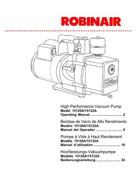
High Performance Vacuum Pump Bombas de VacÃo de Alto ...
High Performance Vacuum Pump Bombas de VacÃo de Alto ...
High Performance Vacuum Pump Bombas de VacÃo de Alto ...

Create successful ePaper yourself
Turn your PDF publications into a flip-book with our unique Google optimized e-Paper software.
<strong>High</strong> <strong>Performance</strong> <strong>Vacuum</strong> <strong>Pump</strong><br />
Mo<strong>de</strong>l 15120A/15122A<br />
Operating Manual .................................. 2<br />
<strong>Bombas</strong> <strong>de</strong> Vacío <strong>de</strong> <strong>Alto</strong> Rendimiento<br />
Mo<strong>de</strong>lo 15120A/15122A<br />
Manuel <strong>de</strong>l Operador ............................ 8<br />
Pompe à Vi<strong>de</strong> à Haut Ren<strong>de</strong>ment<br />
Modèle 15120A/15122A<br />
Manuel d’utilisation ............................. 16<br />
Hochleistungs-Vakuumpumpe<br />
Mo<strong>de</strong>lle 15120A/15122A<br />
Bedienungsanleitung .......................... 24
Operating Manual<br />
2<br />
Table of Contents<br />
Warnings ................................................................ 2<br />
CoolTechr ® high performance<br />
vacuum pumps ................................................. 2<br />
<strong>Pump</strong> components ........................................... 3<br />
Before using your vacuum pump ......................... 3<br />
To use the gas ballast feature .............................. 4<br />
To shut down your pump after use ...................... 4<br />
To maintain your high vacuum pump .................. 4<br />
<strong>Vacuum</strong> pump oil .............................................. 4<br />
Oil change procedure ....................................... 4<br />
Cleaning your pump ......................................... 5<br />
Motor lubrication ............................................... 5<br />
Troubleshooting gui<strong>de</strong> ........................................... 5<br />
Failure to start ................................................... 5<br />
Oil leakage ........................................................ 5<br />
Failure to pull a good vacuum ......................... 5<br />
VacuMaster ® specifications .................................. 5<br />
When you need help ............................................. 6<br />
Replacement parts ................................................ 6<br />
Warranty coverage ................................................ 6<br />
Out of warranty ................................................. 6<br />
For use on A/C-R systems<br />
using CFCs, HCFCs and HFCs<br />
in conjunction with mineral oil,<br />
ester oil, alkylbenzene oil and<br />
PAG oil as lubricants. Not for<br />
use with ammonia or lithium<br />
bromi<strong>de</strong> systems. Not for use<br />
with flammable refrigerants.<br />
U.S Patents 4,523,897; 5,209.653.<br />
Other U.S. and Foreign Patents Pending.<br />
Warnings<br />
When working with refrigerants, goggles should<br />
always be worn. Contact with refrigerants may<br />
cause injury.<br />
Improper use or connections may cause<br />
electrical shock hazards. Read and follow the<br />
instructions carefully and take precautions to<br />
avoid electrical shock hazards. Be sure that all<br />
associated <strong>de</strong>vices are properly groun<strong>de</strong>d before<br />
energizing circuits.<br />
The normal operating temperature will cause<br />
certain external portions of the pump to be hot to<br />
the touch. Do not touch the pump housing or<br />
motor during operation.<br />
VacuMaster ® <strong>High</strong><br />
<strong>Performance</strong> <strong>Vacuum</strong> <strong>Pump</strong>s<br />
Congratulations on purchasing one of Robinair’s<br />
top quality VacuMaster ® vacuum pumps. Your<br />
pump has been engineered specifically for air<br />
conditioning and refrigeration service, and is built<br />
with Robinair’s proven offset rotary vane for fast,<br />
thorough evacuation.<br />
You’ll appreciate these key features...<br />
Iso-Valve TM<br />
Allows the pump to be shut off while still connected<br />
to the A/C-R system, which is handy for<br />
checking rate of rise. With the valve handle in the<br />
“Open” position, the pump is open to the system<br />
being evacuated. In the “Close” position, the pump<br />
is isolated from the system.<br />
<strong>High</strong> vacuum rating<br />
The two-stage, offset rotary vane <strong>de</strong>sign provi<strong>de</strong>s<br />
powerful, quiet high vacuum capability and<br />
assures moisture removal, while the high pumping<br />
capacity reduces evacuation time.<br />
Lifetime Filtration<br />
The intake filter prevents foreign matter from<br />
entering the pumping chamber, and an exhaust<br />
filter separates oil vapor from the exhaust flow.<br />
Gas ballast<br />
A precise amount of atmospheric air is introduced<br />
into the pump, preventing con<strong>de</strong>nsation of<br />
moisture vapor and helping maintain the purity of<br />
the pump oil. By using the gas ballast, the pump<br />
operates more efficiently and pump life is exten<strong>de</strong>d.<br />
Sure-grip handle<br />
The one-piece, mol<strong>de</strong>d handle makes it easy to<br />
carry the pump to and from job sites, and the<br />
handle stays cool to the touch during operation.<br />
Compact <strong>de</strong>sign<br />
Your pump measures approximately 42 cm<br />
(16 1 /2”) long, while aluminum housing and offset<br />
rotary vanes keep the pump weight low, making<br />
it easy to carry.<br />
NOTICE: Airborne<br />
Noise Emissions<br />
This equipment has been tested<br />
for airborne noise emission per<br />
the Council Directive for Machinery<br />
(89/392/EEC) Section 1.7.4<br />
Instructions — Essential Health<br />
and Safety Requirements. Sound<br />
levels do not exceed 80dB(A)<br />
actual value.
<strong>Pump</strong> components<br />
1. Intake Fitting<br />
2. Gas Ballast Valve (located<br />
besi<strong>de</strong> handle)<br />
3. Exhaust Filter<br />
4. Oil Fill Port<br />
5. Sight Glass<br />
6. Die-Cast Aluminum Housing<br />
7. Oil Drain<br />
8. Mol<strong>de</strong>d Polycarbonate Base<br />
9. Iso-Valve TM — Isolates the pump<br />
from the system<br />
10. Powerful, <strong>High</strong> Torque Motor<br />
11. Power Switch<br />
12. Sure-Grip Handle<br />
Before using your<br />
vacuum pump<br />
In all cases, motors are <strong>de</strong>signed for operating<br />
voltages plus or minus 10% of the normal rating<br />
(see SPECIFICATIONS). Single voltage motors<br />
are supplied fully connected and ready to<br />
operate.<br />
1. Check to make certain the voltage and<br />
frequency at the outlet match the specifications<br />
on the pump motor <strong>de</strong>cal. Check the<br />
ON-OFF switch to be sure it is in the OFF<br />
position before you plug the pump into an<br />
outlet. Check to be certain the gas ballast<br />
valve is closed. Remove and discard the red<br />
plastic plug from the top of the oil reservoir.<br />
Failure To Remove Red Plastic Caplug<br />
May Result In Bodily Injury.<br />
2. The pump is shipped without oil in the<br />
reservoir. Before starting the pump, fill with<br />
oil until oil just shows in the bottom of the<br />
sight glass. The approximate oil capacity of<br />
the pump is 488 milliliters (16 1 /2 ounces).<br />
3. Thread in the exhaust filter (hand tighten)<br />
and remove the cap from one of the inlet<br />
ports. Turn the Iso-Valve to OPEN. Turn the<br />
motor switch to ON. When the pump runs<br />
smoothly, turn the Iso-Valve to CLOSED and<br />
replace the cap on the inlet port. This may<br />
take from two to 30 seconds <strong>de</strong>pending on<br />
the ambient temperature. After the pump<br />
runs for approximately one minute, check the<br />
sight glass for proper oil level — oil should be<br />
even with the sight glass OIL LEVEL line.<br />
Add oil if necessary.<br />
When the pump is running, the oil level should be<br />
even with the OIL LEVEL line. Un<strong>de</strong>rfilling will<br />
result in poor vacuum performance. Overfilling<br />
can result in oil blowing from the exhaust.<br />
Your pump is now ready to evacuate air conditioning<br />
and refrigeration systems. Follow normal<br />
service procedures and the A/C-R manufacturer’s<br />
instructions for connections to the system.<br />
CAUTION! Before connecting your vacuum pump<br />
to an A/C-R system, remove refrigerant from the<br />
system in an accepted manner. Damage to the<br />
pump may occur if evacuation is started while the<br />
system is un<strong>de</strong>r high pressure. Robinair recommends<br />
use of our Refrigerant Recovery and<br />
Recycling equipment.<br />
Operating Manual<br />
3
Operating Manual<br />
4<br />
Wiring Instructions (15121A):<br />
The VacuMaster vacuum pump features dual voltage<br />
ranges. Before operating the pump, read and<br />
follow these rewiring instructions (if necessary) to<br />
be sure your pump is wired for the appropriate<br />
voltage.<br />
CAUTION! Unplug the unit before beginning any<br />
service work. Improper use or connections can<br />
cause electrical shock. Only qualified personnel<br />
should perform service work.<br />
The VacuMaster vacuum pump is factory wired<br />
for a high voltage of 220 volts. To wire the switch<br />
for a low voltage range of 110 volts to 127 volts,<br />
follow these steps.<br />
1. Disconnect the unit from the AC power<br />
source before proceeding.<br />
2. Loosen the screws on the plate at the rear of<br />
the motor, and carefully move the plate asi<strong>de</strong><br />
to clear the opening.<br />
3. Disconnect the leads and reconnect for low<br />
voltage, following the diagram and chart.<br />
(<strong>High</strong> voltage connections are also shown<br />
if you want to rewire at some time.)<br />
4. Check to see that all connections are secure<br />
and that there are no short circuits. Be sure<br />
the grounding connector is properly connected.<br />
5. Re-install the plate on the rear of motor with<br />
the screws which were loosened in Step 2.<br />
IMPORTANT: Check for short circuits using a<br />
continuity tester before reconnecting to the AC<br />
power source.<br />
15121A<br />
To use the gas ballast feature<br />
Moisture from the A/C-R system that is carried<br />
into the pump as a vapor tends to con<strong>de</strong>nse into a<br />
liquid and combine with the vacuum pump oil.<br />
When moisture contaminates the pump oil, it<br />
reduces the pump’s ability to reach its ultimate<br />
<strong>de</strong>ep vacuum level.<br />
The gas ballast valve purges a small amount of<br />
atmospheric air through the exhaust chamber.<br />
This extra volume of air mixes with the vapor from<br />
the refrigerant system to prevent con<strong>de</strong>nsation<br />
and to help exhaust moisture in the form of vapor<br />
from the pump.<br />
To use the gas ballast, start the pump and open<br />
the gas ballast valve until the system has reached<br />
approximately 1000-3000 microns. Close the valve<br />
to allow the pump to pull down to its ultimate<br />
vacuum level. The gas ballast valve is located<br />
besi<strong>de</strong> the handle, opposite the inlet fitting.<br />
The gas ballast valve may be opened or closed at<br />
any time during pump operation. It is fully open at<br />
two turns counterclockwise.<br />
NOTE: Robinair recommends the use of a<br />
thermistor vacuum gauge to most accurately<br />
measure vacuum levels.<br />
To shut down your<br />
pump after use<br />
To help prolong pump life and promote easy<br />
starting, follow these procedures for shutdown:<br />
1. Close the manifold valve between the pump<br />
and the system.<br />
2. Turn the Iso-Valve to the CLOSED position.<br />
3. Remove the hose from the pump inlet.<br />
4. Turn the pump power switch to OFF, then return<br />
the Iso-Valve to the OPEN position for a few<br />
seconds to relieve any vacuum insi<strong>de</strong> the pump.<br />
5. Cap the inlet port to prevent any contamination<br />
or loose particles from entering the port.<br />
To maintain your high<br />
vacuum pump<br />
For maximum performance, Robinair recommends<br />
changing vacuum pump oil after each use.<br />
<strong>Vacuum</strong> pump oil<br />
The condition and type of oil used in any high<br />
vacuum pump are extremely important in <strong>de</strong>termining<br />
the ultimate attainable vacuum. Robinair recommends<br />
the use of our Premium <strong>High</strong> <strong>Vacuum</strong><br />
<strong>Pump</strong> Oil. This oil has been specifically blen<strong>de</strong>d to<br />
maintain maximum viscosity at normal running<br />
temperatures and to improve cold weather starts.<br />
Robinair Premium <strong>High</strong> <strong>Vacuum</strong> <strong>Pump</strong> Oil is<br />
available in convenient pint, quart or gallon<br />
containers. Or<strong>de</strong>r by part number:<br />
13201 — Pint (shipped 12 pints per case)<br />
13203 — Quart (shipped 12 quarts per case)<br />
13204 — Gallon (shipped 4 gallons per case)<br />
Oil change procedure<br />
1. Be sure the pump is warmed up.<br />
2. Remove the OIL DRAIN cap. Drain contaminated<br />
oil into a suitable container and dispose<br />
of properly. Oil can be forced from the pump<br />
by opening the inlet and partially blocking the<br />
exhaust with a cloth while the pump is<br />
running. Do not operate the pump for more<br />
than 20 seconds using this method.<br />
3. When the flow of oil has stopped, tilt the<br />
pump forward to drain residual oil.
4. Replace the OIL DRAIN cap. Remove the<br />
exhaust filter and fill the reservoir with new<br />
vacuum pump oil until the oil just shows at the<br />
bottom of the sight glass. The approximate oil<br />
capacity of the pump is 488 milliliters (16 1 /2<br />
ounces).<br />
5. Be sure the inlet ports are capped, then turn<br />
ON the pump. Allow it to run for one minute,<br />
then check the oil level. If the oil is below the<br />
sight glass OIL LEVEL line, add oil slowly<br />
(with the pump running) until the oil reaches<br />
the OIL LEVEL line. Replace the exhaust filter<br />
(hand tighten), making sure the inlet is<br />
capped and the drain cap is tight.<br />
6. If the oil is badly contaminated with sludge<br />
that forms when water is allowed to collect in<br />
the oil, you may need to remove the oil<br />
reservoir cover and wipe it out.<br />
Repeat this procedure as required until the<br />
contamination is removed. Replace the OIL<br />
DRAIN cap and refill the reservoir to the proper<br />
level with fresh pump oil (see Step 4).<br />
Cleaning your pump<br />
Clean the pump with soap and water only. Do not<br />
use commercial cleaners that contain <strong>de</strong>greasing<br />
agents that can damage polycarbonates. The<br />
pump handle and base are ma<strong>de</strong> of Lexan*, one<br />
of the toughest polycarbonate plastics available.<br />
However, it is sensitive to <strong>de</strong>greasing agents.<br />
*Lexan is a registered tra<strong>de</strong>mark of General Electric<br />
Motor lubrication<br />
After three years of normal service or one year of<br />
heavy-duty service, add oil annually. Use electric<br />
motor oil or SAE 10 oil.<br />
Troubleshooting gui<strong>de</strong><br />
Your VacuMaster pump has been <strong>de</strong>signed for <strong>de</strong>pendable<br />
use and long life. If something should go<br />
wrong, however, the following gui<strong>de</strong> will help you get<br />
the pump back into service as quickly as possible.<br />
If disassembly of the pump is required, please<br />
check your warranty. The warranty may be voi<strong>de</strong>d<br />
by misuse or customer tampering which results in<br />
the pump being inoperable.<br />
Failure to start<br />
Check the line voltage. Robinair pumps are <strong>de</strong>signed<br />
to start at +10% line voltage at 0 o C (32 o F).<br />
At extremes, however, switching between the start<br />
and run windings may occur.<br />
Oil leakage<br />
1. Be sure the oil is not a residual accumulation<br />
from spillage, etc.<br />
2. If leakage exists, the module cover gasket or<br />
the shaft seal may need replacing. Follow the<br />
instructions in the seal replacement kit, part<br />
number 15367. If leakage exists in the area of<br />
the oil drain plug, you may need to reseal the<br />
plug using a commercial pipe thread sealer.<br />
Failure to pull a good vacuum<br />
1. Be sure the Iso-Valve is in the OPEN position.<br />
2. Be sure the vacuum gauge and all connections<br />
are in good conditon and leak-free. You can<br />
confirm leakage by monitoring the vacuum<br />
with a thermistor gauge while applying vacuum<br />
pump oil at connections or suspected leak<br />
points. The vacuum will improve briefly while<br />
the oil is sealing the leak.<br />
3. Be sure the pump oil is clean. A badly<br />
contaminated pump may require several oil<br />
flushes. See OIL CHANGE PROCEDURE.<br />
NOTE: Use only high vacuum pump oil such as<br />
Robinair’s Premium <strong>High</strong> <strong>Vacuum</strong> <strong>Pump</strong> Oil. Other<br />
oils will prevent pull-down to a <strong>de</strong>ep vacuum.<br />
4. Be sure the gas ballast knob is tightly closed.<br />
5. Be sure the oil is at the proper level. For<br />
maximum pump operation, the oil must be<br />
even with the OIL LEVEL line on the sight<br />
glass when the pump is running. Do not<br />
overfill. To check the oil level, start the pump<br />
with the inlet capped. Add oil if necessary.<br />
VacuMaster ® specifications<br />
Mo<strong>de</strong>l 15120A<br />
Frequency Range .......................................... 60 Hz<br />
Voltage Range ................................................ 115V<br />
Free Air Displacement................. 283 l/m (10 cfm)<br />
Stages .................................................................... 2<br />
Motor Speed ............................................ 1725 rpm<br />
Factory Micron Rating .......................... 20 microns<br />
Approximate Oil Capacity .......... 488 ml (16 1 /2 oz.)<br />
Weight ........................................ 17.24 kg (38 lbs.)<br />
Width ............................................. 14.29 cm (5 5 /8”)<br />
Height ............................................ 27.3 cm (10 3 /4”)<br />
Length ........................................... 41,9 cm (16 1 /2”)<br />
Intake .................................... 1 /2” and 1 /4” SAE MFL<br />
Min. Starting Temp. (at 90% Voltage) ..0 o C (32 o F)<br />
Motor Size .......................... 1 /2 HP, Capacitor Start<br />
Operating Temp. ............................... 74 o C (165 o F)<br />
Mo<strong>de</strong>l 15122A<br />
Frequency Range ..................................... 50/60 Hz<br />
Free Air Displacement................. 283 l/m (10 cfm)<br />
236 l/m @ 50 Hz<br />
Stages .................................................................... 2<br />
Motor Speed .................................. 1450/1725 rpm<br />
Voltage Range ................................................ 240V<br />
Factory Micron Rating .......................... 20 microns<br />
Approximate Oil Capacity .......... 488 ml (16 1 /2 oz.)<br />
Weight ........................................ 18.60 kg (41 lbs.)<br />
Width ............................................. 14.29 cm (5 5 /8”)<br />
Height ............................................ 27.3 cm (10 3 /4”)<br />
Length ........................................... 44,5 cm (17 1 /2”)<br />
Intake .................................... 1 /2” and 1 /4” SAE MFL<br />
Min. Starting Temp. (at 90% Voltage) ..0 o C (32 o F)<br />
Motor Size ...........0,37 kw ( 1 /2 HP) Capacitor Start<br />
Operating Temp. ............................... 74 o C (165 o F)<br />
Operating Manual<br />
5
Operating Manual<br />
Note:<br />
1. All motors are internally protected (automatic<br />
reset).<br />
2. Operating temperatures are typical for normal<br />
operating conditions.<br />
When you need help<br />
If these procedures do not correct the problem,<br />
contact your nearest Robinair distributor. The<br />
distributor may recommend an additional replacement<br />
part (this manual contains a parts list) or<br />
suggest you send your pump to the nearest<br />
authorized service center.<br />
Because of ongoing product improvements,<br />
we reserve the right to change <strong>de</strong>sign, specifications,<br />
or materials without notice.<br />
12<br />
11<br />
10<br />
9<br />
8<br />
Replacement parts<br />
Part<br />
Figure Part No.<br />
Oil Drain Cap (6) 1 40572<br />
Oil Drain Kit (inclu<strong>de</strong>s # 1, 2) -- 48116<br />
Module Cover Kit(# 1, 2, 3, 5, 18) -- 15139<br />
Exhaust Filter 4 15147<br />
Gas Ballast Knob and Seal 7 15371<br />
Intake Fitting (inclu<strong>de</strong>s # 8, 9, 10) -- 15364<br />
Intake Cap (2), 1 /2” SAE MFL 9 41135<br />
Intake Cap (6), 1 /4” SAE MFL 10 41139<br />
Handle Bolt (inclu<strong>de</strong>s O-ring) 11 15146<br />
Handle, Power Cord, Switch Assy.12 15366<br />
15120A Motor and Handle Assy. 13 15136<br />
15122A Motor and Handle Assy. 13 15143<br />
Coupling 14 48103<br />
Iso-Valve TM Assembly 15 15368<br />
Base and Foot Assembly 16 15369<br />
<strong>Pump</strong> Assembly (# 1-10, 14-19) -- 15138<br />
Seal Replacement Kit (not shown) -- 15367<br />
Warranty coverage<br />
Robinair VacuMaster vacuum pumps are warranted<br />
against <strong>de</strong>fects in material and workmanship for<br />
one year of normal use from the date of purchase.<br />
See your distributor for warranty <strong>de</strong>tails.<br />
Out of warranty<br />
A pump which is no longer covered by the one-year<br />
warranty period and which fails to operate properly<br />
should be returned to the distributor with a full written<br />
explanation of the problem. Before returning an outof-warranty<br />
pump, review all maintenance procedures<br />
to avoid an unnecessary return. Replacement parts<br />
are available for doing your own service.<br />
7<br />
13<br />
14<br />
6<br />
5<br />
15<br />
4<br />
16<br />
17<br />
3<br />
18<br />
6<br />
INST0189<br />
19 2 1
Contenido<br />
<strong>Bombas</strong> <strong>de</strong> vacío <strong>de</strong> alto rendimiento<br />
VacuMaster ® .......................................................... 7<br />
Componentes <strong>de</strong> la bomba .............................. 8<br />
Advertencias .......................................................... 8<br />
Antes <strong>de</strong> utilizar su bomba <strong>de</strong> vacío..................... 9<br />
Para utilizar el balasto <strong>de</strong> gas ............................. 10<br />
Para apagar la bomba <strong>de</strong>spués <strong>de</strong> utilizarla ...... 10<br />
Para mantener su bomba <strong>de</strong> alto vacío ............. 10<br />
Aceite <strong>de</strong> la bomba <strong>de</strong> vacío .......................... 10<br />
Procedimiento para cambios <strong>de</strong> aceite ......... 10<br />
Limpieza <strong>de</strong> la bomba .................................... 11<br />
Lubricación <strong>de</strong> motor ...................................... 11<br />
Guía para la resolución <strong>de</strong> problemas ............... 11<br />
Fallas <strong>de</strong> arranque .......................................... 11<br />
Fugas <strong>de</strong> aceite .............................................. 11<br />
Vacío <strong>de</strong>ficiente .............................................. 11<br />
Especificaciones <strong>de</strong> las bombas<br />
VacuMaster ® ........................................................ 12<br />
Repuestos ............................................................ 13<br />
Cuando usted necesita ayuda ............................ 13<br />
Cobertura <strong>de</strong> la garantía ..................................... 13<br />
Período <strong>de</strong> garantía ........................................ 13<br />
Para los sistemas A/C-R que<br />
utilizan los CFC, HCFC, y HFC<br />
en combinación con aceite<br />
mineral, aceite <strong>de</strong> éster, aceite<br />
aiquilbenceno y aceite PAG<br />
como lubricantes. No para uso<br />
con sistemas <strong>de</strong> amoníaco o<br />
bromuro <strong>de</strong> litio. No para uso<br />
con refrigerantes combustibles.<br />
<strong>Bombas</strong> <strong>de</strong> vacío <strong>de</strong> alto<br />
rendimiento VacuMaster ®<br />
Felicitaciones por su compra <strong>de</strong> una bomba<br />
<strong>de</strong> vacío VacuMaster ® <strong>de</strong> óptima calidad <strong>de</strong><br />
Robinair. Su bomba ha sido diseñada específicamente<br />
para servicios <strong>de</strong> aire acondicionado<br />
y refrigeración y está construida con el álabe<br />
rotatorio compensado <strong>de</strong> la Robinair para tener<br />
una comprobada evacuación rápida y completa.<br />
Ud. va a apreciar estas características...<br />
Iso-Valve TM<br />
Permite que la bomba se cierre mientras está<br />
conectada todavía al sistema <strong>de</strong> A/C-R, lo cual es<br />
conveniente para controlar el ritmo <strong>de</strong> aumento.<br />
Con el mango <strong>de</strong> la válvula en la posición “Open,”<br />
la bomba está abierta al sistema que está siendo<br />
evacuado. En la posición “Close,” la bomba está<br />
aislada <strong>de</strong>l sistema.<br />
<strong>Alto</strong> vacío nominal<br />
El diseño <strong>de</strong>l álabe rotatorio compensado <strong>de</strong> dos<br />
etapas ofrece una capacidad <strong>de</strong> alto vacío<br />
po<strong>de</strong>rosa, pero silenciosa, y asegura la<br />
eliminación <strong>de</strong> la humedad, mientras que la fuerte<br />
capacidad <strong>de</strong> bombeo reduce el tiempo <strong>de</strong><br />
evacuación.<br />
Filtración durante la Vida Util<br />
El filtro <strong>de</strong> entrada evita que materias extrañas<br />
entren a la cámara <strong>de</strong> bombeo, y un filtro <strong>de</strong><br />
escape separa el vapor <strong>de</strong> aceite <strong>de</strong>l flujo <strong>de</strong><br />
escape.<br />
Balasto <strong>de</strong> gas<br />
Una cantidad precisa <strong>de</strong> aire atmosférico se<br />
introduce en la bomba, previniendo la con<strong>de</strong>nsación<br />
<strong>de</strong>l vapor <strong>de</strong> humedad y ayudando a mantener<br />
la pureza <strong>de</strong>l aceite <strong>de</strong> la bomba. Al utilizar<br />
el balasto <strong>de</strong> gas, la bomba opera con mayor<br />
eficiencia y se extien<strong>de</strong> la vida <strong>de</strong> la bomba.<br />
Mango <strong>de</strong> agarre seguro<br />
El mango mol<strong>de</strong>ado <strong>de</strong> una sola pieza hace que<br />
sea fácil <strong>de</strong> transportar la bomba a diferentes<br />
lugares <strong>de</strong> trabajo, y no se calienta durante la<br />
operación.<br />
Diseño compacto<br />
Su bomba mi<strong>de</strong> aproximadamente 42 cm (16 1 /2”)<br />
<strong>de</strong> largo, y la caja <strong>de</strong> aluminio y álabes rotatorios<br />
compensados aligeran el peso <strong>de</strong> la bomba,<br />
haciéndola fácil <strong>de</strong> llevar.<br />
Operating Manual<br />
7
Manual <strong>de</strong>l Operador<br />
Componentes <strong>de</strong> la bomba<br />
1. Conectador <strong>de</strong> la Entrada<br />
2. Válvula <strong>de</strong> Balasto <strong>de</strong> Gas (ubicada al lado<br />
<strong>de</strong>l mango)<br />
3. Filtro <strong>de</strong> Escape<br />
4. Puerto para el Llenado <strong>de</strong> Aceite<br />
5. Tubo Indicador<br />
6. Caja Mol<strong>de</strong>ada <strong>de</strong> Aluminio<br />
7. Drenaje <strong>de</strong> Aceite<br />
8. Base Mol<strong>de</strong>ada <strong>de</strong> Policarbonatos<br />
9. Iso-Valve TM — aísla la bomba <strong>de</strong>l sistema<br />
10. Potente Motor <strong>de</strong> <strong>Alto</strong> Torque<br />
11. Interruptor Eléctrico<br />
12. Mango <strong>de</strong> Agarre Seguro<br />
Advertencias<br />
Cuando se trabaja con refrigerantes, siempre se<br />
<strong>de</strong>be usar gafas protectoras. El contacto con<br />
refrigerantes pue<strong>de</strong> causar daños a su persona.<br />
El uso o conexiones ina<strong>de</strong>cuados pue<strong>de</strong>n crear<br />
situaciones <strong>de</strong> peligro <strong>de</strong> shock eléctrico. Lea y<br />
siga las instrucciones cuidadosamente y tome<br />
precauciones para evitar estos peligros.<br />
Asegúrese <strong>de</strong> que todos los dispositivos<br />
asociados estén a<strong>de</strong>cuadamente conectados a<br />
tierra antes <strong>de</strong> pasar energía a los circuitos.<br />
La temperatura normal <strong>de</strong> operación hará que<br />
ciertas porciones externas <strong>de</strong> la bomba se<br />
calienten. No toque la caja <strong>de</strong> la bomba o el motor<br />
durante su operación.<br />
NOTICIA: Emisiones Aerotransportadas <strong>de</strong> Ruido<br />
Este equipo ha sido probado para emisiones aerotransportadas<br />
<strong>de</strong> ruido según la Directiva <strong>de</strong>l Consejo para Maquinaria (89/392/<br />
EEC), Sección 1.7.4 Instrucciones — Requisitos Esenciales <strong>de</strong><br />
Salud y Seguridad. El nivel <strong>de</strong> ruido no sobrepasa el valor<br />
actual <strong>de</strong> 88dB(A).<br />
8
Antes <strong>de</strong> utilizar<br />
su bomba <strong>de</strong> vacío<br />
En todos los casos, los motores están diseñados<br />
para voltajes <strong>de</strong> trabajo con una variación <strong>de</strong>l +10%<br />
<strong>de</strong>l valor nominal (ver ESPECIFICACIONES).<br />
Los motores <strong>de</strong> voltaje sencillo se suministran<br />
completamente conectados y listos para functionar.<br />
1. Asegúrese <strong>de</strong> que el voltaje y la frecuencia<br />
en la salida se conformen con las especificaciones<br />
en la calcomanía <strong>de</strong>l motor <strong>de</strong> la<br />
bomba. Revise el interruptor (ON-OFF) para<br />
asegurar que está en la posición <strong>de</strong> OFF<br />
antes <strong>de</strong> enchufar la bomba. Verifique que la<br />
válvula <strong>de</strong> balasto <strong>de</strong> gas esté cerrada.<br />
Saque y bote el tapón <strong>de</strong> plástico <strong>de</strong>l extremo<br />
<strong>de</strong>l filtro <strong>de</strong> escape.<br />
2. La bomba se envía sin aceite en el<br />
reservorio; antes <strong>de</strong> arrancarla, hay que<br />
llenarlo <strong>de</strong> aceite. Saque el filtro <strong>de</strong> escape<br />
(un tapón hecho <strong>de</strong> plástico negro que está<br />
directamente al frente al mango) y agregue<br />
aceite justamente hasta que aparezca en el<br />
fondo <strong>de</strong>l tubo indicador. La bomba tiene una<br />
capacidad aproximada <strong>de</strong> aceite <strong>de</strong> 375 ml.<br />
3. Reemplace el filtro <strong>de</strong> escape (apriete a<br />
mano), y remueva la tapa <strong>de</strong> uno <strong>de</strong> los<br />
puertos <strong>de</strong> entrada. Ponga la Iso-válvula en<br />
la posición ABIERTO (Open). Gire el<br />
interruptor <strong>de</strong> motor a ENCENDIDO (On).<br />
Cuando la bomba funcione suavemente,<br />
ponga la Iso-válvula en la posición<br />
CERRADO (Closed) y reemplace la tapa <strong>de</strong>l<br />
puerto <strong>de</strong> entrada. Esto pue<strong>de</strong> requerir <strong>de</strong><br />
dos a 30 segundos <strong>de</strong>pendiendo <strong>de</strong> la<br />
temperatura ambiente. Después <strong>de</strong> que la<br />
bomba funcione por aproximadamente un<br />
minuto, verifique el nivel a<strong>de</strong>cuado <strong>de</strong>l aceite<br />
en el cristal visor — el aceite <strong>de</strong>be estar<br />
nivelado con la línea <strong>de</strong> NIVEL DE ACEITE<br />
(Oil level) <strong>de</strong>l cristal visor. Añada más aceite<br />
si es necesario.<br />
Cuando la bomba está funcionando, el aceite <strong>de</strong>be<br />
estar al nivel <strong>de</strong> la línea <strong>de</strong> NIVEL DE ACEITE<br />
(Oil level). Una cantidad <strong>de</strong>masiado baja resultará<br />
en un vacío <strong>de</strong>ficiente. Una cantidad <strong>de</strong>masiado<br />
gran<strong>de</strong> resultará en la salida <strong>de</strong> aceite por el escape.<br />
Ahora su bomba está lista para evacuar sistemas <strong>de</strong><br />
aire acondicionado y refrigeración. Para conectar la<br />
bomba al sistema, siga los procedimientos normales<br />
<strong>de</strong> servicio y las instrucciones <strong>de</strong>l fabricante.<br />
CUIDADO! Antes <strong>de</strong> conectar la bomba <strong>de</strong> vacío<br />
al sistema <strong>de</strong> A/C-R, elimine el refrigerante <strong>de</strong>l<br />
sistema <strong>de</strong> una manera aceptable. Pue<strong>de</strong>n<br />
producirse daños en la bomba si se inicia la<br />
evacuación mientras el sistema está bajo mucha<br />
presión. La Robinair recomienda el uso <strong>de</strong><br />
nuestros equipos <strong>de</strong> Recuperación y Reciclaje <strong>de</strong><br />
Refrigerantes.<br />
Instrucciones para la instalación<br />
alámbrica <strong>de</strong>l interruptor (15121A):<br />
Los bombas <strong>de</strong> vacío VacuMaster ofrecen rangos<br />
duales <strong>de</strong> voltaje. Antes <strong>de</strong> operar la bomba, lea y<br />
siga estas instrucciones para cambios <strong>de</strong><br />
alambrado (si esto fuera necesario) para asegurar<br />
que su bomba esté preparada para el voltaje<br />
apropiado.<br />
CUIDADO! Desenchufe la unidad antes <strong>de</strong> iniciar<br />
cualquier trabajo <strong>de</strong> servicio. El uso o conexiones<br />
ina<strong>de</strong>cuados pue<strong>de</strong>n causar shock eléctrico.<br />
Solamente personal calificado <strong>de</strong>be realizar<br />
trabajos <strong>de</strong> servicio.<br />
Los bombas <strong>de</strong> vacío VacuMaster vienen <strong>de</strong> la<br />
fábrica listos para <strong>de</strong> alto voltaje <strong>de</strong> 220 voltios.<br />
Para cambiar el alambrado a un rango <strong>de</strong> bajo<br />
voltaje <strong>de</strong> 100 a 127 voltios, siga estos pasos:<br />
1. Desconecte la unidad <strong>de</strong> la fuente <strong>de</strong> po<strong>de</strong>r<br />
<strong>de</strong> corriente alterna (AC) antes <strong>de</strong> proce<strong>de</strong>r.<br />
2. Afloje los tornillos <strong>de</strong> la placa en el lado<br />
posterior <strong>de</strong>l motor y coloque cuidadosamente<br />
a un lado la placa para <strong>de</strong>spejar la<br />
entrada.<br />
3. Desconecte los avances y reconecte para el<br />
bajo voltaje, siguiendo el diagrama y el<br />
cuadro en la siguiente página. (Las<br />
conexiones <strong>de</strong> alto voltaje también están<br />
indicadas por si acaso quisiera volver a la<br />
configuración original alguna vez.)<br />
4. Verifique que las todas las conexiones estén<br />
bien sujetadas y que no haya cortocircuitos.<br />
También <strong>de</strong> que la conexión a tierra esté bien<br />
hecha.<br />
5. Reinstale la placa en el lado posterior <strong>de</strong>l<br />
motor con los tornillos que se aflojaron en el<br />
paso 2.<br />
IMPORTANTE: Antes <strong>de</strong> volver a conectar con la<br />
fuente <strong>de</strong> po<strong>de</strong>r, revise para ver si hay<br />
cortocircuitos utilizando un medidor <strong>de</strong><br />
continuidad.<br />
1<br />
➀ Tornillo Para La<br />
Puesta A Tierra<br />
➁ Nota: Las<br />
conexiones eléctricas<br />
externas siempre<br />
se conectan con las<br />
terminales 1 y 2.<br />
➂ Avances Eléctricos<br />
2<br />
3<br />
4<br />
5 6 7<br />
8<br />
9<br />
15121A<br />
➃ Conexión Interna<br />
De Voltaje<br />
➄ Avance Del Motor<br />
➅ Bajo Voltaje<br />
➆ <strong>Alto</strong> Voltaje<br />
➇ Marrón<br />
➈ Blanco<br />
➉ Púrpura<br />
Manual <strong>de</strong>l Operador<br />
9
Para utilizar el<br />
balasto <strong>de</strong> gas<br />
Para mantener su<br />
bomba <strong>de</strong> alto vacío<br />
Manual <strong>de</strong>l Operador<br />
La humedad que la bomba se lleva <strong>de</strong>l sistema<br />
A/C-R, en forma <strong>de</strong> vapor, tien<strong>de</strong> a con<strong>de</strong>nsarse<br />
y este líquido se une al aceite <strong>de</strong> la bomba <strong>de</strong><br />
vacío. Cuando el aceite <strong>de</strong> la bomba se contamina<br />
<strong>de</strong> humedad, esto reduce la capacidad <strong>de</strong> la bomba<br />
<strong>de</strong> alcanzar su máximo nivel <strong>de</strong> alto vacío.<br />
La válvula <strong>de</strong>l balasto <strong>de</strong> gas purga una pequeña<br />
cantidad <strong>de</strong> aire atmosférico a través <strong>de</strong> la<br />
cámara <strong>de</strong> escape. Este volumen adicional <strong>de</strong> aire<br />
se mezcla con el vapor <strong>de</strong>l sistema <strong>de</strong> refrigerante<br />
para evitar la con<strong>de</strong>nsación y facilitar la salida <strong>de</strong><br />
humedad <strong>de</strong> la bomba en forma <strong>de</strong> vapor.<br />
Para utilizar el balasto <strong>de</strong> gas, arranque la bomba<br />
y abra la válvula <strong>de</strong> balasto <strong>de</strong> gas hasta que el<br />
sistema haya llegado a aproximadamente<br />
1000-3000 (mil) micrones. Cierre la válvula para<br />
permitir que la bomba llegue a su máximo nivel <strong>de</strong><br />
vacío. La válvula <strong>de</strong>l balasto <strong>de</strong> gas está ubicada<br />
al lado <strong>de</strong>l mango, frente al conectador <strong>de</strong> la entrada.<br />
La válvula <strong>de</strong>l balasto <strong>de</strong> gas pue<strong>de</strong> estar abierta<br />
o cerrada en cualquier momento durante la<br />
operación <strong>de</strong> la bomba. Está totalmente abierta<br />
con dos vueltas en la dirección contraria al<br />
movimiento <strong>de</strong> las manecillas <strong>de</strong>l reloj.<br />
NOTA: La Robinair recomienda el uso <strong>de</strong> un<br />
manómetro <strong>de</strong> vacío tipo termistor para medir los<br />
niveles <strong>de</strong> vacío <strong>de</strong> la manera más precisa.<br />
Para apagar la<br />
bomba <strong>de</strong>spués <strong>de</strong> utilizarla<br />
Para ayudar a prolongar la vida útil <strong>de</strong> la bomba y<br />
facilitar el arranque, siga estos procedimientos<br />
para apagarla.<br />
1. Cierre la válvula <strong>de</strong>l múltiple entre la bomba y<br />
el sistema.<br />
2. Ponga la Iso-válvula en la posición<br />
CERRADO (Closed).<br />
3. Remueva la manguera <strong>de</strong> la entrada <strong>de</strong> la<br />
bomba.<br />
4. Ponga el interruptor <strong>de</strong> energía para la<br />
bomba en la posición PARADO (Off), luego<br />
ponga la Iso-válvula en la posición ABIERTO<br />
(Open) <strong>de</strong> nuevo, por unos segundos para<br />
eliminar el vacío <strong>de</strong>l interior <strong>de</strong> la bomba.<br />
5. Tape el puerto <strong>de</strong> entrada para prevenir<br />
cualquier contaminación o entrada <strong>de</strong><br />
partículas flojas en el puerto.<br />
Para un máximo rendimiento, Robinair<br />
recomienda que se cambie el aceite <strong>de</strong> la bomba<br />
<strong>de</strong> vacío <strong>de</strong>spués <strong>de</strong> cada uso.<br />
Aceite <strong>de</strong> la bomba <strong>de</strong> vacío<br />
La condición y el tipo <strong>de</strong> aceite utilizado en<br />
cualquier bomba <strong>de</strong> alto vacío son sumamente<br />
importantes en la <strong>de</strong>terminación <strong>de</strong>l máximo vacío<br />
alcanzable. Robinair recomienda el uso <strong>de</strong><br />
nuestro Aceite Premium para <strong>Bombas</strong> <strong>de</strong> <strong>Alto</strong><br />
Vacío. Este aceite ha sido mezclado<br />
específicamente para mantener la viscosidad<br />
máxima a temperaturas normales <strong>de</strong> trabajo y<br />
para mejorar los arranques en temporadas frías.<br />
Aceite Premium para <strong>Bombas</strong> <strong>de</strong> <strong>Alto</strong> Vacío <strong>de</strong><br />
Robinair es disponible en recipientes<br />
convenientes <strong>de</strong> un octavo <strong>de</strong> galón (0,475 l),<br />
cuarto <strong>de</strong> galón (0,95 l) o un galón (3,8 l). Haga<br />
los pedidos por los números <strong>de</strong> repuesto:<br />
13201 — Octavo (enviados 12 octavos por caja)<br />
13203 — Cuartos (enviados 12 cuartos por caja)<br />
13204 — Galón (enviados 4 galones por caja)<br />
Procedimiento para cambios <strong>de</strong> aceite<br />
1. Asegúrese <strong>de</strong> calentar la bomba.<br />
2. Saque la tapa OIL DRAIN. Drene el aceite<br />
contaminado en un recipiente apropiado y<br />
disponga <strong>de</strong>l mismo a<strong>de</strong>cuadamente. El<br />
aceite pue<strong>de</strong> ser forzado a salir <strong>de</strong> la bomba<br />
al abrir la entrada y bloquear parcialmente el<br />
escape con una tela mientras la bomba está<br />
funcionando. No opere la bomba por más <strong>de</strong><br />
20 segundos utilizando este método.<br />
3. Cuando se haya <strong>de</strong>tenido el flujo <strong>de</strong> aceite,<br />
incline la bomba hacia a<strong>de</strong>lante para drenar<br />
el aceite residual.<br />
4. Vuelva a colocar la tapa OIL DRAIN. Saque<br />
el filtro <strong>de</strong> escape y llene el reservorio con el<br />
nuevo aceite para bombas <strong>de</strong> vacío<br />
justamente hasta que aparezca en el fondo<br />
<strong>de</strong>l tubo indicador. La bomba tiene una<br />
capacidad aproximada <strong>de</strong> aceite <strong>de</strong> 488 ml<br />
(16 1 /2 oz.).<br />
5. Asegúrese <strong>de</strong> que estén tapados los puertos<br />
<strong>de</strong> entrada y luego encienda la bomba<br />
(póngala en ON). Permita que funcione<br />
durante un minuto y luego revise el nivel <strong>de</strong>l<br />
aceite. Si el aceite está por <strong>de</strong>bajo <strong>de</strong> la línea<br />
OIL LEVEL, agregue más aceite lentamente<br />
(mientras funciona la bomba) hasta que<br />
alcance la línea. Reemplace el filtro <strong>de</strong><br />
escape (apriete a mano), asegurándose <strong>de</strong><br />
que la entrada esté tapada y que la tapa <strong>de</strong>l<br />
drenaje esté bien ajustada.<br />
10
6. Si el aceite está muy contaminado con<br />
fangos que se forman cuando permite que el<br />
agua permanezca en el aceite, pue<strong>de</strong> ser<br />
necessario remover la tapa <strong>de</strong>l recipiente <strong>de</strong><br />
aceite y limpario.<br />
Repita este procedimiento las veces que sean<br />
necesarias hasta que se elimine la contaminación.<br />
Vuelva a colocar la tapa OIL DRAIN y vuelva<br />
a llenar el reservorio con aceite fresco para<br />
bombas hasta el nivel apropiado (ver el paso 4).<br />
Limpieza <strong>de</strong> la bomba<br />
Limpie la bomba con agua y jabón. No utilice los<br />
limpiadores comerciales que contienen<br />
agentes <strong>de</strong>sengrasadores que pue<strong>de</strong>n dañar<br />
los policarbonatos. La manilla y la base <strong>de</strong> la<br />
bomba son construidas <strong>de</strong> Lexan, uno <strong>de</strong> los<br />
plásticos policarbonatos más duros. Sin embargo<br />
es sensible a los agentes <strong>de</strong>sengrasadores.<br />
*Lexan es una marca registrada <strong>de</strong> General Electric<br />
Lubricación <strong>de</strong> motor<br />
Después <strong>de</strong> tres años <strong>de</strong> servicio normal o un año<br />
<strong>de</strong> servicio pesado, añada aceite anualmente.<br />
Use aceite <strong>de</strong> motor eléctrico o aceite SAE 10.<br />
Guía para la<br />
resolución <strong>de</strong> problemas<br />
Su bomba VacuMaster ha sido diseñada para<br />
ofrecer un servicio confiable y una larga vida útil.<br />
Sin embargo, si hubiera una falla, la siguiente<br />
guía le ayudará a tener la bomba funcionando <strong>de</strong><br />
nuevo lo más rápidamente posible.<br />
Si se requiere <strong>de</strong>smontar la bomba, favor <strong>de</strong><br />
revisar su garantía. La garantía pue<strong>de</strong> ser<br />
anulada por la mala utilización o por trabajos<br />
realizados por personas no autorizadas,<br />
incluyendo al cliente, cuando estos resultan en la<br />
inoperabilidad <strong>de</strong> la bomba.<br />
Fallas <strong>de</strong> arranque<br />
Revise el voltaje <strong>de</strong> la línea eléctrica. Las bombas<br />
Robinair están diseñadas para arrancar a 0 o C<br />
(32 o F) a un voltaje <strong>de</strong> línea con una variación <strong>de</strong><br />
+10%. Sin embargo, bajo condiciones extremas,<br />
pue<strong>de</strong>n producirse conmutación entre los<br />
bobinados <strong>de</strong> arranque y <strong>de</strong> operación.<br />
Fugas <strong>de</strong> aceite<br />
1. Asegúrese <strong>de</strong> que el aceite no sea residuos<br />
<strong>de</strong> un <strong>de</strong>rrame, etc.<br />
2. Si existe una fuga, pue<strong>de</strong> ser necesario<br />
reemplazar el empaque <strong>de</strong> la tapa <strong>de</strong>l módulo<br />
o el sello <strong>de</strong>l eje. Siga las instrucciones<br />
suministradas con el juego <strong>de</strong> repuesto <strong>de</strong>l<br />
sello, repuesto número 15367. Si existe una<br />
fuga en el área <strong>de</strong>l tapón <strong>de</strong> drenaje, pue<strong>de</strong><br />
ser necesario volver a sellarlo utilizando un<br />
sellador comercial para la rosca <strong>de</strong> la tubería.<br />
Vacío <strong>de</strong>ficiente<br />
1. Asegúrese <strong>de</strong> que la Iso-Valve <strong>de</strong> la bomba<br />
esté en la posición abierta (OPEN).<br />
2. Asegúrese <strong>de</strong> que el manómetro <strong>de</strong> vacío y<br />
todas las conexiones estén en buen estado y<br />
libre <strong>de</strong> fugas. Se pue<strong>de</strong> confirmar una fuga<br />
a través <strong>de</strong> un manómetro tipo termistor<br />
mientras se vaya aplicando aceite para<br />
bombas <strong>de</strong> vacío en las conexiones o los<br />
puntos en don<strong>de</strong> se sospecha que pueda<br />
presentarse una fuga.<br />
3. Asegúrese <strong>de</strong> que el aceite <strong>de</strong> la bomba esté<br />
limpio. Una bomba muy contaminada pue<strong>de</strong><br />
requerir varios enjuagues <strong>de</strong> aceite. Ver el<br />
PROCEDIMIENTO PARA CAMBIOS DE<br />
ACEITE.<br />
NOTA: Use solamente aceite para bombas <strong>de</strong> alto<br />
vacío tal como el Aceite Premium para <strong>Bombas</strong><br />
<strong>de</strong> <strong>Alto</strong> Vacío Robinair. Otros aceites previenen la<br />
realización <strong>de</strong> un vacío fuerte.<br />
4. Verifique que la válvula <strong>de</strong> balasto <strong>de</strong> gas<br />
esté bien cerrada.<br />
5. Asegúrese <strong>de</strong> que el aceite esté en el nivel<br />
apropiado. Para el máximo rendimiento <strong>de</strong> la<br />
bomba, el aceite tiene que estar en el nivel<br />
<strong>de</strong> la línea OIL LEVEL en el tubo indicador<br />
cuando la bomba está funcionando. Ver el<br />
PROCEDIMIENTO PARA CAMBIOS DE<br />
ACEITE. No cargue la bomba con <strong>de</strong>masiado<br />
aceite. Para revisar el nivel <strong>de</strong>l aceite,<br />
arranque la bomba con la entrada tapada.<br />
Agregue aceite si es necesario.<br />
Manual <strong>de</strong>l Operador<br />
11
Especificaciones <strong>de</strong> las<br />
bombas VacuMaster ®<br />
Manual <strong>de</strong>l Operador<br />
Mo<strong>de</strong>lo 15120A<br />
Rango <strong>de</strong> Frecuencia .................................... 60 Hz<br />
Desplazamiento Libre <strong>de</strong> Aire .... 283 l/m (10 cfm)<br />
Etapas .................................................................... 2<br />
Velocidad <strong>de</strong> Motor ................................ 1.725 rpm<br />
Rango <strong>de</strong> Voltaje ............................................ 115V<br />
Valor Nominal <strong>de</strong> la Fábrica .............. 20 micrones<br />
Capacidad Aprox. <strong>de</strong> Aceite ...... 488 ml (16 1 /2 oz.)<br />
Peso ........................................... 17.24 kg (38 lbs.)<br />
Anchura ......................................... 14,29 cm (5 5 /8”)<br />
Altura ............................................. 27,3 cm (10 3 /4”)<br />
Longitud ........................................ 41,9 cm (16 1 /2”)<br />
Entrada ...................................... 1 /2” y 1 /4” SAE MFL<br />
Temp. Mínima <strong>de</strong> Arranque<br />
(a voltaje <strong>de</strong> 90%) ................................. 0 o C (32 o F)<br />
Tamaño <strong>de</strong>l Motor ......................................... 1 /2 HP<br />
Arranque por Capacitor<br />
Temp. <strong>de</strong> Trabajo .............................. 74 o C (165 o F)<br />
Mo<strong>de</strong>lo 15122A<br />
Rango <strong>de</strong> Frecuencia ............................... 50/60 Hz<br />
Desplazamiento Libre <strong>de</strong> Aire .... 283 l/m (10 cfm)<br />
236 l/m @ 50 Hz<br />
Etapas .................................................................... 2<br />
Velocidad <strong>de</strong> Motor ....................... 1450/1725 rpm<br />
Rango <strong>de</strong> Voltaje ............................................ 240V<br />
Valor Nominal <strong>de</strong> la Fábrica .............. 20 micrones<br />
Capacidad Aprox. <strong>de</strong> Aceite ...... 488 ml (16 1 /2 oz.)<br />
Peso ........................................... 18.60 kg (41 lbs.)<br />
Anchura ......................................... 14,29 cm (5 5 /8”)<br />
Altura ............................................. 27,3 cm (10 3 /4”)<br />
Longitud ........................................ 44,5 cm (17 1 /2”)<br />
Entrada ...................................... 1 /2” y 1 /4” SAE MFL<br />
Temp. Mínima <strong>de</strong> Arranque<br />
(a voltaje <strong>de</strong> 90%) ................................. 0 o C (32 o F)<br />
Tamaño <strong>de</strong>l Motor ........................ 0,37 kw ( 1 /2 HP)<br />
Arranque por Capacitor<br />
Temp. <strong>de</strong> Trabajo .............................. 74 o C (165 o F)<br />
Nota:<br />
1. Todos los motores llevan protección interna<br />
(con reactivación automática).<br />
2. Las temperaturas <strong>de</strong> trabajo son típicas para<br />
condiciones normales <strong>de</strong> operación.<br />
Patentes EE.UU. 4.523.897; 5,209.653. Otras<br />
patentes pendientes en los Estados Unidos y<br />
otros países.<br />
Debido al continuo mejoramiento <strong>de</strong> los<br />
productos, nos reservamos el <strong>de</strong>recho <strong>de</strong><br />
cambiar diseños, especificaciones y<br />
materiales sin previo aviso.<br />
12
12<br />
11<br />
9<br />
8<br />
10<br />
7<br />
13<br />
14<br />
6<br />
5<br />
15<br />
4<br />
INST0189<br />
Repuestos<br />
Repuesto<br />
Figura Número<br />
Tapa para Drenaje <strong>de</strong> Aceite (6) 1 40572<br />
Juego <strong>de</strong> Drenaje <strong>de</strong> Aceite<br />
(incluye #1 y #2) -- 48116<br />
Juego <strong>de</strong> Cubierta <strong>de</strong> Módulo<br />
(incluye #1, #2, #3, #5 y #18) -- 15139<br />
Filtro <strong>de</strong> escape 4 15147<br />
Válvula y sello <strong>de</strong>l balasto <strong>de</strong> gas 7 15371<br />
Conectador <strong>de</strong> Entrada<br />
(incluye #8, #9 y #10) -- 15364<br />
Tapa <strong>de</strong> Entrada (2),<br />
1<br />
/2" SAE MFL 9 41135<br />
Tapa <strong>de</strong> Entrada (6),<br />
1<br />
/4" SAE MFL 10 41139<br />
Tuerca <strong>de</strong> Mango<br />
(incluye juntas tórica) 11 15146<br />
Conjunto Mango-Cable<br />
Eléctrico-Interruptor 12 15366<br />
15120A Conjunto Motor-Mango 13 15136<br />
15122A Conjunto Motor-Mango 13 15143<br />
Acople 14 48103<br />
Conjunto <strong>de</strong> Válvula (Iso-Valve TM ) 15 15368<br />
Conjunto Base-Pie 16 15369<br />
Conjunto <strong>de</strong> Bomba,<br />
(incluye #1-10 y #14-19) -- 15138<br />
Juego <strong>de</strong> Reemplazo<br />
<strong>de</strong>l Sello (no ilustrado) -- 15367<br />
16<br />
17<br />
18<br />
Cuando usted necesita ayuda<br />
Si estos procedimientos no resuelven el<br />
problema, comuníquese con el distribuidor más<br />
cercano. El distribuidor pue<strong>de</strong> recomendar una<br />
pieza <strong>de</strong> repuesto adicional (este manual contiene<br />
una lista <strong>de</strong> repuestos) o sugiere que envíe la<br />
bomba al centro <strong>de</strong> servicio autorizado.<br />
Cobertura <strong>de</strong> la garantía<br />
Las bombas <strong>de</strong> vacío VacuMaster <strong>de</strong> Robinair<br />
están garantizadas contra <strong>de</strong>fectos <strong>de</strong> materiales<br />
y fabricación durante un año <strong>de</strong> uso normal <strong>de</strong>s<strong>de</strong><br />
la fecha <strong>de</strong> adquisición. Para los <strong>de</strong>talles <strong>de</strong> la<br />
garantía, comuníquese con el distribuidor.<br />
Período <strong>de</strong> garantía<br />
19 2 1<br />
Una bomba que ya no esté cubierta por el período<br />
<strong>de</strong> garantía <strong>de</strong> un año que <strong>de</strong>je <strong>de</strong> funcionar<br />
a<strong>de</strong>cuadamente <strong>de</strong>be ser <strong>de</strong>vuelta al distribuidor<br />
con una explicación completa <strong>de</strong>l problema por<br />
escrito. Antes <strong>de</strong> <strong>de</strong>volver una bomba sin<br />
garantía, revise todos los procedimientos <strong>de</strong><br />
mantenimiento para evitar la <strong>de</strong>volución<br />
innecesaria. Están disponibles repuestos para<br />
que usted realice su propio servicio <strong>de</strong><br />
mantenimiento.<br />
3<br />
Manual <strong>de</strong>l Operador<br />
13
Manuel d’utilisation<br />
Sommaire<br />
Pompes à vi<strong>de</strong> VacuMaster ®<br />
à haut ren<strong>de</strong>ment ................................................. 14<br />
Composants <strong>de</strong> la pompe .............................. 15<br />
Avertissements .................................................... 15<br />
Avant d’utiliser la pompe à vi<strong>de</strong> .......................... 16<br />
Utilisation du dispositif <strong>de</strong> lest <strong>de</strong> gaz ................ 17<br />
Arrêt <strong>de</strong> la pompe après usage........................... 17<br />
Entretien <strong>de</strong> la pompe à vi<strong>de</strong><br />
à haut ren<strong>de</strong>ment ................................................. 17<br />
Huile <strong>de</strong> la pompe à vi<strong>de</strong> ................................ 17<br />
Instructions pour le changement d’huile ........ 17<br />
Nettoyage <strong>de</strong> la pompe .................................. 18<br />
Lubrification <strong>de</strong> moteur ................................... 18<br />
Gui<strong>de</strong> <strong>de</strong> détection <strong>de</strong>s pannes .......................... 18<br />
La pompe ne démarre pas ............................. 18<br />
Il y a une fuite d’huile ...................................... 18<br />
Il est impossible d’obtenir<br />
un haut niveau <strong>de</strong> vi<strong>de</strong> ................................... 18<br />
Spécifications <strong>de</strong> la pompe VacuMaster ® .......... 19<br />
Pièces <strong>de</strong> rechange ............................................. 20<br />
En cas <strong>de</strong> besoin d’assistance ........................... 20<br />
Garantie ................................................................ 20<br />
Hors garantie .................................................. 20<br />
Pour les systèmes A/C-R,<br />
utilisant les CFC, HCFC et HFC<br />
en conjonction avec <strong>de</strong> l’huile<br />
minérale, <strong>de</strong> l‘huile ester, <strong>de</strong><br />
l’huile <strong>de</strong> benzène d’alkyle et<br />
<strong>de</strong> l’huile PAG comme<br />
lubrifiants. Ne pas utiliser sur<br />
les systèmes à ammoniaque<br />
ou bromure <strong>de</strong> lithium. Ne pas<br />
utiliser avec <strong>de</strong>s réfrigérants<br />
inflammables.<br />
Pompes à vi<strong>de</strong> VacuMaster ®<br />
à haut ren<strong>de</strong>ment<br />
Nous vous félicitons d’avoir opté pour un modèle<br />
<strong>de</strong> pompes à vi<strong>de</strong> VacuMaster ® <strong>de</strong> haute gamme.<br />
Cette pompe a été spécifiquement conçue pour<br />
entretenir les installations <strong>de</strong> climatisation et <strong>de</strong><br />
réfrigération et comporte un dispositif à ailettes<br />
rotatives Robinair qui a fait ses preuves et qui<br />
assure une évacuation rapi<strong>de</strong> et complète.<br />
Ces qualités sont là pour vous servir au mieux...<br />
Soupape Iso-Valve TM<br />
Elle permet d’arrêter la pompe tout en la laissant<br />
branchée sur le système A/C-R, ce qui est<br />
commo<strong>de</strong> pour vérifier les niveaux. Lorsque la<br />
manette <strong>de</strong> soupape est en position “Open,” la<br />
pompe s’ouvre au système en cours d’évacuation.<br />
Lorsqu’elle est en position “Close,” elle est isolée<br />
du système.<br />
Régime nominal <strong>de</strong> vi<strong>de</strong> poussé<br />
Sa conception à <strong>de</strong>ux étages et à <strong>de</strong>ux ailettes<br />
rotatives donne à la pompe une capacité <strong>de</strong> vi<strong>de</strong><br />
puissante et silencieuse ainsi que la possibilité <strong>de</strong><br />
prélever l’humidité; cette forte capacité <strong>de</strong><br />
pompage réduit le temps d’évacuation.<br />
Filtration et durée <strong>de</strong> vie<br />
Le filtre d’aspiration retient toute matière<br />
étrangère à l’entrée <strong>de</strong> la chambre <strong>de</strong> pompage et<br />
un filtre d’échappement interne sépare la vapeur<br />
d’huile du flux d’échappement.<br />
Lest <strong>de</strong> gaz<br />
Un volume précis d’air est introduit dans la<br />
pompe, ce qui empêche la con<strong>de</strong>nsation <strong>de</strong> la<br />
vapeur d’humidité et ai<strong>de</strong> à maintenir la pureté <strong>de</strong><br />
l’huile. En utilisant le lest <strong>de</strong> gaz, la pompe opère<br />
plus efficacement et sa durée <strong>de</strong> vie est rallongée.<br />
Poignée <strong>de</strong> prise sûre<br />
Cette poignée moulée, faite d’une seule pièce,<br />
facilite le transport <strong>de</strong> la pompe <strong>de</strong> chantier en<br />
chantier. Elle reste froi<strong>de</strong> lorsque la pompe<br />
fonctionne.<br />
Conception compacte<br />
La pompe, qui mesure environ 42 cm (16 1 /2”) <strong>de</strong><br />
long, est légère grâce à son boîtier en aluminium<br />
et ses ailettes rotatives, et dès lors facile à<br />
transporter.<br />
14
Composants <strong>de</strong> la pompe<br />
1. Raccord d’aspiration<br />
2. Soupape <strong>de</strong> lest <strong>de</strong> gaz (située près du socle<br />
<strong>de</strong> la poignée)<br />
3. Filtre d’echappement<br />
4. Orifice <strong>de</strong> remplissage d’huile<br />
5. Hublot <strong>de</strong> regard<br />
6. Boîtier en aluminium moulé<br />
7. Orifice <strong>de</strong> vidange d’huile<br />
8. Socle en polycarbonate moulé<br />
9. Soupape Iso-Valve TM — permet d’isoler la<br />
pompe du système<br />
10. Moteur puissant à fort couple<br />
11. Interrupteur d’alimentation<br />
12. Poignée à prise sûre<br />
Avertissements<br />
Pour travailler avec <strong>de</strong>s réfrigérants, le port <strong>de</strong><br />
lunettes protectrices est obligatoire car le contact<br />
avec les réfrigérants peut occasionner <strong>de</strong>s<br />
blessures.<br />
Une utilisation inappropriée ou <strong>de</strong>s connexions mal<br />
faites peuvent être sources <strong>de</strong> chocs électriques.<br />
Lire soigneusement les instructions et prendre<br />
toutes les précautions nécessaires pour éviter les<br />
chocs électriques. S’assurer que tous les appareils<br />
associés à la pompe sont correctement mis à la<br />
masse avant <strong>de</strong> mettre les circuits sous tension.<br />
La température normale <strong>de</strong> fonctionnement<br />
provoquera le réchauffement <strong>de</strong> certaines parties<br />
extérieures <strong>de</strong> la pompe. Ne pas toucher le boîtier<br />
<strong>de</strong> la pompe ou le moteur pendant que la pompe<br />
fonctionne.<br />
Manuel d’utilisation<br />
NOTICE: Emissions <strong>de</strong> Bruits Aériens<br />
Cet équipment a été testé pour les émissions <strong>de</strong> bruits aériens<br />
selon la Directive du Conseil pour la Machinerie (89/392/EEC),<br />
Section 1.7.4 Instructions — Prescriptions Essentielles <strong>de</strong> Santé<br />
<strong>de</strong> Sécurité. Les niveaux sonores ne doivent pas excé<strong>de</strong>r<br />
88dB(A) en valeur effective.<br />
15
Manuel d’utilisation<br />
16<br />
Avant d’utiliser<br />
la pompe à vi<strong>de</strong><br />
Dans tous les cas, les moteurs sont conçus pour<br />
fonctionner avec <strong>de</strong>s tensions <strong>de</strong> fonctionnement<br />
<strong>de</strong> plus ou moins 10% <strong>de</strong> la tension nominale (cf.<br />
SPECIFICATIONS). Des moteurs à voltage unique<br />
sont livrés tout connectés et prêts à l’emploi.<br />
1. Vérifier que les spécifications <strong>de</strong> tension et <strong>de</strong><br />
fréquence mentionnées sur la plaque<br />
d’i<strong>de</strong>ntification du moteur correspon<strong>de</strong>nt bien<br />
à celles <strong>de</strong> la prise <strong>de</strong> courant. Faire attention<br />
que l’interrupteur ON-OFF soit en position<br />
OFF avant <strong>de</strong> brancher la pompe dans une<br />
prise. Vérifier que la soupape <strong>de</strong> lest <strong>de</strong> gaz<br />
est fermée. Retirer et jeter le bouchon en<br />
plastique <strong>de</strong> l’extrémité du filtre<br />
d’échappement.<br />
2. La pompe est livrée sans huile dans le<br />
réservoir. Avant <strong>de</strong> démarrer la pompe, il faut<br />
remplir le réservoir d’huile. Retirer le filtre<br />
d’échappement (bouchon noir en plastique<br />
situé <strong>de</strong>vant la poignée) et ajouter <strong>de</strong> l’huile<br />
jusqu’à ce qu’on la voit apparaître au fond du<br />
hublot <strong>de</strong> regard. La capacité <strong>de</strong> la pompe en<br />
huile est d’environ 488 millilitres (16 1 /2 oz).<br />
3. Remplacer le filtre d’échappement (serrer à la<br />
main) et enlever le bouchon <strong>de</strong> l’un <strong>de</strong>s<br />
orifices d’admission. Mettre la soupape Isovalve<br />
en position ouverte (OPEN). Placer le<br />
commutateur moteur sur ON. Une fois la<br />
pompe mise en route, mettre la soupape Isovalve<br />
en position fermée (CLOSED) et<br />
replacer le capuchon sur l’orifice d’admission.<br />
L’opération dure entre 2 et 30 secon<strong>de</strong>s<br />
suivant la température ambiante. Après avoir<br />
laissé la pompe fonctionner pendant une<br />
minute environ, vérifier le niveau d’huile dans<br />
le hublot <strong>de</strong> regard : l’huile doit atteindre la ligne<br />
OIL LEVEL. Ajouter <strong>de</strong> l’huile si nécessaire.<br />
Lorsque la pompe fonctionne, le niveau d’huile<br />
doit arriver au trait du hublot <strong>de</strong> regard l’huile doit<br />
atteindre la ligne OIL LEVEL. Si le niveau est inférieur,<br />
le ren<strong>de</strong>ment sera moindre en termes <strong>de</strong> vi<strong>de</strong> réalisé.<br />
Si le niveau est supérieur, <strong>de</strong> l’huile s’échappera<br />
éventuellement <strong>de</strong> l’orifice d’échappement.<br />
La pompe est maintenant prête à évacuer les<br />
systèmes <strong>de</strong> climatisation et <strong>de</strong> réfrigération.<br />
Suivre les procédures normales d’entretien et les<br />
instructions du fabricant <strong>de</strong> systèmes A/C-R<br />
concernant le branchement <strong>de</strong> la pompe au système.<br />
ATTENTION! Avant <strong>de</strong> brancher la pompe à vi<strong>de</strong><br />
sur un système A/C-R, retirer le réfrigérant du<br />
système en suivant la métho<strong>de</strong> habituelle. Si<br />
l’évacuation commence alors que le système est<br />
sous haute pression, la pompe encourt <strong>de</strong>s<br />
dommages. Robinair recomman<strong>de</strong> l’utilisation <strong>de</strong><br />
son équipement <strong>de</strong> récupération et <strong>de</strong> recyclage<br />
du réfrigérant.<br />
Instructions relatives au cablâge (15121A):<br />
La pompe à vi<strong>de</strong> VacuMaster ® est disponible en<br />
bitension. Avant d’utiliser la pompe, lire et suivre<br />
les instructions <strong>de</strong> recâblage (si nécessaire) afin<br />
que la pompe soit réglée sur la tension<br />
appropriée.<br />
ATTENTION! Débrancher la pompe avant<br />
d’entreprendre tout travail d’entretien. Une<br />
utilisation ou <strong>de</strong>s connexions inappropriées<br />
peuvent causer <strong>de</strong>s chocs électriques. Seul un<br />
personnel qualifié doit réaliser le travail <strong>de</strong><br />
maintenance.<br />
La pompe à vi<strong>de</strong> VacuMaster est câblée en usine<br />
pour une haute tension <strong>de</strong> 220 volts. Pour<br />
brancher le commutateur qui permet <strong>de</strong> se régler<br />
sur une basse tension <strong>de</strong> 110 á 127 volts, il<br />
convient d’adopter la procédure suivante:<br />
1. Avant <strong>de</strong> procé<strong>de</strong>r, débrancher l’appareil <strong>de</strong><br />
la source <strong>de</strong> courant.<br />
2. Desserrer les vis du plateau à l’arrière du<br />
moteur et déplacer avec précaution le plateau<br />
sur le côté pour dégager l’ouverture.<br />
3. Débrancher les conducteurs principaux et les<br />
rebrancher pour une basse tension, suivant le<br />
schéma et le tableau <strong>de</strong> la page opposée (les<br />
connexions <strong>de</strong> haute tension sont aussi<br />
indiquées pour le cas où l’on veuille recâbler).<br />
4. S’assurer que toutes les connexions sont<br />
sures et qu’il n’y a pas <strong>de</strong> court-circuits.<br />
S’assurer que la prise <strong>de</strong> terre est bien<br />
branchée.<br />
5. Réinstaller le plateau à l’arrière du moteur<br />
avec les vis qui ont été <strong>de</strong>sserrées à l’étape 2.<br />
IMPORTANT : Vérifier l’absence <strong>de</strong> court-circuits<br />
à l’ai<strong>de</strong> d’un testeur <strong>de</strong> continuité avant <strong>de</strong><br />
rebrancher l’appareil à la source <strong>de</strong> courant.<br />
➀<br />
➁<br />
➂<br />
➃<br />
➄<br />
➅<br />
➆<br />
➇<br />
➈<br />
➉<br />
1<br />
2<br />
3<br />
4<br />
5 6 7<br />
Vis De Mise A La Terre<br />
Remarque : Les conducteurs d’alimentation<br />
externe sont toujours connectés aux<br />
terminaux 1 et 2.<br />
Conducteurs Principaux<br />
Connexion <strong>de</strong> Tension Interne<br />
Conducteur Principal De Moteur<br />
Basse Tension<br />
Haute Tension<br />
Marron<br />
Blanc<br />
Violet<br />
8<br />
9<br />
15121A
Utilisation du<br />
dispositif <strong>de</strong> lest <strong>de</strong> gaz<br />
Entretien <strong>de</strong> la pompe<br />
à vi<strong>de</strong> à haut ren<strong>de</strong>ment<br />
L’humidité du système A/C-R qui arrive dans la<br />
pompe sous forme <strong>de</strong> vapeur tend à se con<strong>de</strong>nser<br />
en liqui<strong>de</strong> et à se combiner avec l’huile <strong>de</strong> la<br />
pompe. Lorsque l’humidité contamine l’huile <strong>de</strong> la<br />
pompe, la capacité <strong>de</strong> la pompe à atteindre son<br />
niveau optimal <strong>de</strong> vi<strong>de</strong> profond est réduite.<br />
La soupape <strong>de</strong> lest <strong>de</strong> gaz laisse passer une<br />
petite quantité d’air par la chambre<br />
d’échappement. Ce volume supplémentaire d’air<br />
se mélange avec la vapeur du système <strong>de</strong><br />
réfrigérant pour prévenir la con<strong>de</strong>nsation et ai<strong>de</strong>r<br />
à expulser l’humidité <strong>de</strong> la pompe sous forme <strong>de</strong><br />
vapeur.<br />
Pour utiliser la soupape <strong>de</strong> lest <strong>de</strong> gaz, démarrer<br />
la pompe et ouvrir la soupape <strong>de</strong> lest <strong>de</strong> gaz<br />
jusqu’à ce que le système atteigne un vi<strong>de</strong><br />
d’environ 1000-3000 microns. Fermer la soupape<br />
pour que la pompe puisse <strong>de</strong>scendre à son<br />
niveau optimal <strong>de</strong> vi<strong>de</strong>. La soupape <strong>de</strong> lest <strong>de</strong> gaz<br />
est située à côté <strong>de</strong> la poignée, en face du<br />
raccord d’aspiration.<br />
La soupape <strong>de</strong> lest <strong>de</strong> gaz peut être ouverte ou<br />
fermée à n’importe quel moment du<br />
fonctionnement <strong>de</strong> la pompe. Elle est<br />
complètement ouverte lorsqu’on lui fait faire <strong>de</strong>ux<br />
tours dans le sens <strong>de</strong>s aiguilles d’une montre.<br />
REMARQUE : Robinair recomman<strong>de</strong> l’utilisation<br />
d’un manomètre à thermistor pour mesurer le plus<br />
précisément possible les niveaux <strong>de</strong> vi<strong>de</strong>.<br />
Arrêt <strong>de</strong> la<br />
pompe après usage<br />
Afin <strong>de</strong> prolonger la vie <strong>de</strong> la pompe et d’en<br />
faciliter le démarrage, arrêter la pompe en suivant<br />
les instructions ci-après.<br />
1. Fermer le manifold entre la pompe et le<br />
système.<br />
2. Mettre la soupape Iso-valve en position<br />
fermée (CLOSED).<br />
3. Sortir le tuyau à l’entrée <strong>de</strong> la pompe.<br />
4. Mettre l’interrupteur <strong>de</strong> la pompe sur OFF;<br />
remettre ensuite la soupape Iso-valve en<br />
position ouverte (OPEN) pendant quelques<br />
secon<strong>de</strong>s pour dégager tout vi<strong>de</strong> se trouvant<br />
dans la pompe.<br />
5. Boucher l’orifice d’admission pour empêcher<br />
toute contamination ou l’entrée dans l’orifice<br />
<strong>de</strong> particules isolées.<br />
Pour assurer un ren<strong>de</strong>ment maximal, Robinair<br />
recomman<strong>de</strong> <strong>de</strong> changer l’huile <strong>de</strong> la pompe<br />
après chaque utilisation.<br />
Huile <strong>de</strong> la pompe à vi<strong>de</strong><br />
Le type d’huile utilisé pour chaque pompe à vi<strong>de</strong> à<br />
haut ren<strong>de</strong>ment et son état, sont <strong>de</strong>ux facteurs<br />
extrêmement importants pour déterminer le vi<strong>de</strong><br />
maximum possible. Robinair recomman<strong>de</strong><br />
l’utilisation <strong>de</strong> son huile pour pompe à vi<strong>de</strong> à haut<br />
ren<strong>de</strong>ment, <strong>de</strong> qualité supérieure. Cette huile a<br />
été spécifiquement mélangée pour maintenir une<br />
viscosité maximale à <strong>de</strong>s températures normales<br />
<strong>de</strong> fonctionnement et pour améliorer les<br />
démarrages en conditions hivernales.<br />
L’huile <strong>de</strong> qualité supérieure Robinair pour pompe<br />
à vi<strong>de</strong> à haut ren<strong>de</strong>ment est disponible en<br />
conteneurs d’un huitième <strong>de</strong> gallon (pinte ou<br />
0,475 l), d’un quart <strong>de</strong> gallon (0,95 l) ou d’un<br />
gallon (3,8 l).<br />
Pour les comman<strong>de</strong>r, indiquer le numéro <strong>de</strong><br />
référence:<br />
13201 — Pinte (livré par caisse <strong>de</strong> 12 pintes)<br />
13203 — Quart (livré par caisse <strong>de</strong> 12 quarts)<br />
13204 — Gallon (livré par caisse <strong>de</strong> 4 gallons)<br />
Instructions pour le changement d’huile<br />
1. S’assurer que la pompe est chau<strong>de</strong>.<br />
2. Enlever le bouchon <strong>de</strong> l’orifice <strong>de</strong> vidange<br />
d’huile. Verser l’huile contaminée dans un<br />
conteneur approprié et l’éliminer <strong>de</strong> manière<br />
propre. Il est possible d’extirper l’huile <strong>de</strong> la<br />
pompe en ouvrant la bouche d’aspiration et<br />
en bloquant l’échappement avec un tissu<br />
alors que la pompe fonctionne. Si l’on utilise<br />
cette métho<strong>de</strong>, ne pas faire marcher la<br />
pompe plus <strong>de</strong> 20 secon<strong>de</strong>s.<br />
3. Lorsque l’écoulement d’huile s’arrête,<br />
pencher la pompe vers l’avant pour vi<strong>de</strong>r<br />
l’huile qui reste.<br />
4. Replacer le bouchon <strong>de</strong> vidange d’huile.<br />
Retirer le filtre d’échappement et remplir le<br />
réservoir avec <strong>de</strong> l’huile neuve jusqu’à ce que<br />
l’on aperçoive l’huile au fond du hublot <strong>de</strong><br />
regard. La capacité <strong>de</strong> la pompe en huile est<br />
d’environ 488 millilitres (16 1 /2 oz).<br />
5. S’assurer que les orifices d’aspiration sont<br />
bouchés puis mettre la pompe sous tension.<br />
La faire tourner pendant une minute puis<br />
vérifier le niveau d’huile. Si l’huile est en<br />
<strong>de</strong>ssous du repère <strong>de</strong> niveau dans le hublot<br />
<strong>de</strong> regard, en rajouter lentement (en continuant<br />
<strong>de</strong> faire tourner la pompe) jusqu’à ce<br />
qu’elle atteigne le niveau souhaité. Replacer<br />
le filtre d’échappement (serrer à la main) en<br />
s’assurant que l’aspiration est bouchée et que<br />
le bouchon <strong>de</strong> vidange est bien serré.<br />
Manuel d’utilisation<br />
17
Manuel d’utilisation<br />
6. Si l’huile est sérieusement contaminée avec<br />
du cambouis qui se forme lorsque l’eau entre<br />
en contact avec l’huile, il sera peut-être<br />
nécessaire d’enlever le couvercle du<br />
réservoir d’huile et <strong>de</strong> le nettoyer avec un<br />
chiffon.<br />
Répéter la procédure comme indiqué jusqu’à ce<br />
que les contaminants aient disparu. Replacer le<br />
bouchon <strong>de</strong> l’orifice <strong>de</strong> vidange d’huile et remplir<br />
le réservoir avec <strong>de</strong> l’huile propre jusqu’au niveau<br />
adéquat (cf. Etape 4).<br />
Nettoyage <strong>de</strong> la pompe<br />
Ne nettoyer la pompe qu’avec <strong>de</strong> l’eau et du<br />
savon. Ne pas utiliser <strong>de</strong> détergents vendus<br />
dans le commerce contenant <strong>de</strong>s agents<br />
dégraissants qui pourraient endommager les<br />
polycarbonates. La poignée et le socle <strong>de</strong> la<br />
pompe sont fabriqués en Lexan, un <strong>de</strong>s plastiques<br />
polycarbonates les plus résistants. Les agents<br />
dégraissants pourraient toutefois les abîmer.<br />
*Lexan est une marque déposée <strong>de</strong> General Electric<br />
Lubrification <strong>de</strong> moteur<br />
Aprés trois ans <strong>de</strong> service normal ou un an <strong>de</strong><br />
service à haut ren<strong>de</strong>ment, ajouter <strong>de</strong> l’huile<br />
annuellement. Utiliser <strong>de</strong> l’huile pour moteur<br />
électrique ou <strong>de</strong> l’huile SAE 10.<br />
Gui<strong>de</strong> <strong>de</strong> détection <strong>de</strong>s pannes<br />
La conception <strong>de</strong> la pompe VacuMaster est telle<br />
qu’elle garantit une utilisation fiable et durable.<br />
Si toutefois quelque chose ne fonctionne pas, le<br />
présent gui<strong>de</strong> <strong>de</strong>s anomalies permettra <strong>de</strong><br />
remettre la pompe en service aussi rapi<strong>de</strong>ment<br />
que possible.<br />
Si le démontage <strong>de</strong> la pompe s’avère nécessaire,<br />
consulter la garantie. Elle peut ne pas s’appliquer<br />
lorsque la pompe est <strong>de</strong>venue inopérable à la<br />
suite d’une mauvaise utilisation ou d’une altération<br />
par l’utilisateur.<br />
La pompe ne démarre pas<br />
Vérifier la tension <strong>de</strong> la ligne électrique. Les<br />
pompes Robinair sont conçues pour démarrer<br />
à +10% <strong>de</strong> la tension <strong>de</strong> la ligne (chargée) à 0 o C<br />
(32 o F). Aux extrêmes toutefois, un transfert entre<br />
les enroulements <strong>de</strong> démarrage et d’allure<br />
normale peut se produire.<br />
Il y a une fuite d’huile<br />
1. S’assurer que l’huile ne provient pas d’une<br />
accumulation due à un débor<strong>de</strong>ment, etc.<br />
2. Si la fuite existe, il faut peut-être remplacer le<br />
joint <strong>de</strong> couvercle du module ou le joint<br />
d’arbre. Suivre les instructions fournies avec<br />
le kit <strong>de</strong> remplacement <strong>de</strong> joint, pièce<br />
N°15367. Si une fuite existe autour du<br />
bouchon <strong>de</strong> l’orifice <strong>de</strong> vidange,<br />
il faudra éventuellement resceller le bouchon<br />
à l’ai<strong>de</strong> d’un dégrippant commercial.<br />
Il est impossible d’obtenir un haut niveau <strong>de</strong> vi<strong>de</strong><br />
1. S’assurer que la soupape Iso-valve est en<br />
position OPEN.<br />
2. S’assurer que le manomètre et toutes les<br />
connexions sont en bon état et qu’ils ne<br />
présentent pas <strong>de</strong> fuites. On peut confirmer la<br />
présence d’une fuite en contrôlant le vi<strong>de</strong> à<br />
l’ai<strong>de</strong> d’un manomètre à thermistor et en<br />
appliquant <strong>de</strong> l’huile aux jointures ou aux<br />
points <strong>de</strong> fuite qu’on a i<strong>de</strong>ntifiés. Le vi<strong>de</strong><br />
s’améliorera rapi<strong>de</strong>ment dès que l’huile aura<br />
remédié à la fuite.<br />
3. S’assurer que l’huile <strong>de</strong> la pompe est propre.<br />
Si la pompe est gravement contaminée, il<br />
faudra éventuellement lui faire subir plusieurs<br />
lavages d’huile. Cf. la section INSTRUC-<br />
TIONS POUR LE CHANGEMENT D’HUILE.<br />
REMARQUE : N’utiliser que <strong>de</strong> l’huile pour pompe<br />
à vi<strong>de</strong> à haut ren<strong>de</strong>ment telle que l’huile <strong>de</strong> qualité<br />
supérieure Robinair pour pompe à vi<strong>de</strong> à haut<br />
ren<strong>de</strong>ment. Les autres huiles empêcheront<br />
l’obtention d’un vi<strong>de</strong> profond.<br />
4. Vérifier que le bouton <strong>de</strong> lest <strong>de</strong> gaz est bien<br />
fermé.<br />
5. S’assurer que l’huile est au niveau souhaité.<br />
Pour que la pompe fonctionne <strong>de</strong> manière<br />
optimale, il faut, lorsqu’elle marche, que<br />
l’huile atteigne la ligne <strong>de</strong> niveau du hublot <strong>de</strong><br />
regard. Cf. INSTRUCTIONS POUR LE<br />
CHANGEMENT D’HUILE. Ne pas remplir <strong>de</strong><br />
trop le réservoir. Pour vérifier le niveau<br />
d’huile, démarrer la pompe avec la bouche<br />
d’aspiration fermée. Vérifier le niveau d’huile<br />
dans le hublot. Ajouter <strong>de</strong> l’huile si<br />
nécessaire.<br />
18
Spécifications<br />
<strong>de</strong> la pompe VacuMaster ®<br />
Modèle 15120A<br />
Gamme <strong>de</strong> fréquence ................................... 60 Hz<br />
Déplacement libre d’air ............... 283 l/m (10 cfm)<br />
Etages .................................................................... 2<br />
Vitesse du moteur .......................................... 1725<br />
Gamme <strong>de</strong> tension ........................................ 115 V<br />
Niveau micronique <strong>de</strong> fabrication ........ 20 microns<br />
Capacité d’huile approx..............488 ml (16 1 /2 oz.)<br />
Poids ........................................... 17.24 kg (38 lbs.)<br />
Largeur .......................................... 14,29 cm (5 5 /8”)<br />
Hauteur.......................................... 27,3 cm (10 3 /4”)<br />
Longueur ....................................... 41,9 cm (16 1 /2”)<br />
Raccord ................................... 1 /2” et 1 /4” SAE MFL<br />
Température <strong>de</strong> départ<br />
minimum (à 90% <strong>de</strong> tension)................ 0 o C (32 o F)<br />
Capacité du moteur .................... 1 /2 HP Démarreur<br />
Température opérationnelle ............. 74 o C (165 o F)<br />
Modèle 15122A<br />
Gamme <strong>de</strong> fréquence ..............................50/60 Hz<br />
Déplacement libre d’air ............... 283 l/m (10 cfm)<br />
236 l/m @ 50 Hz<br />
Etages .................................................................... 2<br />
Vitesse du moteur ................................. 1450/1725<br />
Gamme <strong>de</strong> tension ........................................ 240 V<br />
Niveau micronique <strong>de</strong> fabrication ........ 20 microns<br />
Capacité d’huile approx..............488 ml (16 1 /2 oz.)<br />
Poids ........................................... 18.60 kg (41 lbs.)<br />
Largeur .......................................... 14,29 cm (5 5 /8”)<br />
Hauteur.......................................... 27,3 cm (10 3 /4”)<br />
Longueur ....................................... 44,5 cm (17 1 /2”)<br />
Raccord ................................... 1 /2” et 1 /4” SAE MFL<br />
Température <strong>de</strong> départ<br />
minimum (à 90% <strong>de</strong> tension)................ 0 o C (32 o F)<br />
Capacité du moteur ... 0,37 kw ( 1 /2 HP) Démarreur<br />
Température opérationnelle ............. 74 o C (165 o F)<br />
Remarque :<br />
1. Tous les moteurs sont protégés à l’intérieur<br />
(remise à zéro automatique).<br />
2. Les températures opérationnelles reflètent<br />
<strong>de</strong>s conditions normales d’opération.<br />
Brevets U.S 4.523,897; 5,209.653.<br />
Autres brevets U.S. et étrangers en instance.<br />
En raison <strong>de</strong>s améliorations continues<br />
apportées au produit, nous nous réservons le<br />
droit <strong>de</strong> modifier, sans notification préalable,<br />
la conception, les spécifications et les<br />
matériaux s’y rapportant.<br />
Manuel d’utilisation<br />
19
12<br />
11<br />
9<br />
8<br />
10<br />
7<br />
13<br />
14<br />
6<br />
5<br />
15<br />
4<br />
Manuel d’utilisation<br />
INST0189<br />
Pièces <strong>de</strong> rechange<br />
Pièce N° Numéro<br />
Capuchon (6) d’orifice<br />
<strong>de</strong> vidange d’huile 1 40572<br />
Orifice <strong>de</strong> vidange d’huile<br />
(comprend N° 1 et 2) -- 48116<br />
Kit <strong>de</strong> couvercle <strong>de</strong> Module<br />
(comprend N° 1, 2, 3, 5 et 18) -- 15139<br />
Filtre d’échappement 4 15147<br />
Bouton <strong>de</strong> lest <strong>de</strong> gaz et joint 7 15371<br />
Raccord d’aspiration<br />
(comprend N° 8, 9 et 10) -- 15364<br />
Bouchon (2) d’aspiration<br />
13mm ( 1 /2” SAE MFL) 9 41135<br />
Bouchon (6) d’aspiration<br />
6 mm ( 1 /4” SAE MFL) 10 41139<br />
Boulon <strong>de</strong> la poignée<br />
(comprend bagues) 11 15146<br />
Poignée, fil électrique et<br />
ensemble interrupteur 12 15366<br />
15120A Ensemble Moteur<br />
et Poignée 13 15136<br />
15122A Ensemble Moteur<br />
et Poignée 13 15143<br />
Raccord 14 48103<br />
Ensemble soupape (Iso-Valve TM ) 15 15368<br />
Ensemble socle et pied 16 15369<br />
Ensemble le Pompe,<br />
(comprend N° 1-10 et 14-19) -- 15138<br />
Kit <strong>de</strong> remplacement <strong>de</strong><br />
joint (non illustré) -- 15367<br />
16<br />
17<br />
18<br />
En cas <strong>de</strong> besoin d’assistance<br />
Si ces procédures ne corrigent pas le problème,<br />
veuillez contacter votre distributeur Robinair le<br />
plus proche. Le distributeur sera en mesure <strong>de</strong><br />
vous recomman<strong>de</strong>r une pièce <strong>de</strong> rechange<br />
supplémentaire (une liste <strong>de</strong> pièces figure dans ce<br />
manuel) ou <strong>de</strong> vous suggérer <strong>de</strong> renvoyer votre<br />
pompe au centre <strong>de</strong> réparation agréé le plus<br />
proche.<br />
Garantie<br />
Les pompes VacuMaster <strong>de</strong> Robinair sont<br />
garanties contre les défauts <strong>de</strong> matériel et <strong>de</strong><br />
fabrication pendant une durée normale<br />
d’utilisation d’un an à partir <strong>de</strong> la date d’achat.<br />
Prendre contact avec le distributeur pour obtenir<br />
les détails concernant l’application <strong>de</strong> cette<br />
garantie.<br />
Hors garantie<br />
19 2 1<br />
Toute pompe dont la pério<strong>de</strong> <strong>de</strong> garantie d’un an<br />
est révolue et qui ne fonctionne plus correctement<br />
doit être retournée au distributeur,<br />
accompagnée d’une lettre expliquant en quoi<br />
consiste le problème. Toutefois, avant <strong>de</strong><br />
renvoyer une pompe qui n’est plus couverte par la<br />
garantie, revoir toutes les procédures d’entretien<br />
afin d’éviter un retour inutile. Des pièces <strong>de</strong><br />
rechange sont disponibles pour l’utilisateur<br />
désireux d’effectuer l’entretien<br />
lui-même.<br />
3<br />
20
Inhaltsverzeichnis<br />
VacuMaster ® Hochleistungs-Vakuumpumpen ... 21<br />
<strong>Pump</strong>enbestandteile ....................................... 22<br />
Warnung ............................................................... 22<br />
Bevor Sie Ihre Vakuumpumpe<br />
in Betrieb nehmen ................................................ 23<br />
Benutzung <strong>de</strong>r Gasballastventile ........................ 24<br />
Abschalten <strong>de</strong>r <strong>Pump</strong>e nach Gebrauch ............. 24<br />
Instandhaltung Ihrer Hochvakuumpumpe .......... 24<br />
Vakuumpumpenöl ........................................... 24<br />
Ölwechselvorgang .......................................... 24<br />
Reinigen ihrer <strong>Pump</strong>e ..................................... 25<br />
Motor Schmierung .......................................... 25<br />
Störungssuch-Hinweise....................................... 25<br />
Springt nicht an ............................................... 25<br />
Öl läuft aus ...................................................... 25<br />
Zieht kein gutes Vakuum ................................ 25<br />
Technische Daten <strong>de</strong>r VacuMaster ®<br />
Vakuumpumpe ..................................................... 26<br />
Ersatzteile............................................................. 27<br />
Wenn Hilfe Beansprucht Wer<strong>de</strong>n Muß ............... 27<br />
Garantie ................................................................ 27<br />
Garantieablauf ................................................ 27<br />
Für Gebrauch an A/C-R<br />
Systemen mit CFCs, HCFCs,<br />
und HFCs in Verbindung mit<br />
Mineralöl, Esteröl, Alkylbenzenöl<br />
und PAG-Öl als<br />
Schmiermittel. Nicht für <strong>de</strong>n<br />
Gebrauch mit Ammoniak o<strong>de</strong>r<br />
Lithiumbromid Systemen.<br />
Nicht für <strong>de</strong>n Gebrauch mit<br />
brennbaren Kühlmitteln.<br />
VacuMaster ® Hochleistungs-<br />
Vakuumpumpen<br />
Wir gratulieren Ihnen zum Kauf einer<br />
Hochqualitäts Robinair VacuMaster ® Vakuumpumpe.<br />
Ihre <strong>Pump</strong>e wur<strong>de</strong> speziell für <strong>de</strong>n<br />
Service an Klima- und Kühlanlagen hergestellt<br />
und sie ist mit Robinairs bewährtem Offsetrotationsflügel<br />
für schnelle, sorgfältige Evakuierung<br />
ausgestattet.<br />
Sie wer<strong>de</strong>n diese wesentlichen Eigenshaften<br />
schätzen...<br />
Iso-Valve TM<br />
Ermöglicht das Ausschalten <strong>de</strong>r <strong>Pump</strong>e während<br />
sie noch an <strong>de</strong>m Klima- Kühlanlagensystem<br />
angeschlossen ist, was praktisch zur Überprüfung<br />
<strong>de</strong>r Anstiegsgeschwindigkeit ist. In<strong>de</strong>m <strong>de</strong>r<br />
Ventilgriff in <strong>de</strong>r “Offen” Position ist, steht die<br />
<strong>Pump</strong>e zu <strong>de</strong>m System das evakuiert wird offen.<br />
In <strong>de</strong>r “Zu” Position ist die <strong>Pump</strong>e vom System<br />
isoliert.<br />
Hoher Vakuumnennwert<br />
Der zweistufig Offsett-Rotationsflügelentwurf<br />
erzeugt kraftvolle, geräuscharme, hohe<br />
Vakuumleistung und versichert die Entfernung von<br />
Feuchtigkeit, während die Hochpumpen-Kapazität<br />
die Evakuierungszeit vermin<strong>de</strong>rt.<br />
Filtrierung auf Lebenszeit<br />
Der Einlaßfilter verhin<strong>de</strong>rt <strong>de</strong>n Eindrang von<br />
Fremdstoffen in die <strong>Pump</strong>enkammer und ein<br />
Ablaßfilter schei<strong>de</strong>t Öldampf von <strong>de</strong>n Ablaßgasen<br />
ab.<br />
Gasballast<br />
Ein genau angegebener Anteil atmosphärischer<br />
Luft wird in die <strong>Pump</strong>e eingezogen, um<br />
Kon<strong>de</strong>nsation von Wasserdampf zu verhin<strong>de</strong>rn<br />
und um die Reinheit <strong>de</strong>s <strong>Pump</strong>enöls zu erhalten.<br />
Die Benutzung <strong>de</strong>s Gasballasts ermöglicht, daß<br />
die <strong>Pump</strong>e leistungsfähiger arbeitet und die<br />
Lebenszeit <strong>de</strong>r <strong>Pump</strong>e verlängert wird.<br />
Rutschsicherer Griff<br />
Ein einzelteiliger, geformter Griff vereinfacht <strong>de</strong>n<br />
Transport <strong>de</strong>r <strong>Pump</strong>e zu und von <strong>de</strong>r Arbeitsstelle<br />
und <strong>de</strong>r Griff bleibt zum Anfassen während <strong>de</strong>s<br />
Betriebs kühl.<br />
Kompakter Entwurf<br />
Ihre <strong>Pump</strong>e ist nur ungefähr 42 cm (16 1 /2”) lang,<br />
wobei ein Gehäuse aus Aluminium und<br />
Offsetrotations-Flügel das <strong>Pump</strong>engewicht niedrig<br />
halten und damit <strong>de</strong>n Transport vereinfachen.<br />
Bedienungsanleitung<br />
21
Bedienungsanleitung<br />
<strong>Pump</strong>enbestandteile<br />
1. Einlaßanschluß<br />
2. Gasballastventil (befin<strong>de</strong>t sich neben <strong>de</strong>r<br />
Griffbasis)<br />
3. Ablaß-Filter<br />
4. Ölfülleingang<br />
5. Sichtglas<br />
6. Druckgußgehäuse aus Aluminium<br />
7. Ölablaß<br />
8. Basis aus geformten Polykarbonat<br />
9. Iso-Valve TM - Isoliert die <strong>Pump</strong>e von <strong>de</strong>m<br />
System<br />
10. Kraftvoller Motor mit hohem Drehmoment<br />
11. Stromschalter<br />
12. Rutschsicherer Griff<br />
Warnung<br />
Tragen Sie immer eine Schutzbrille wenn Sie mit<br />
Kältemitteln arbeiten. Kontakt mit Kältemitteln<br />
könnte Verletzungen verursachen.<br />
Unsachgemäßer Gebrauch o<strong>de</strong>r Verbindungen<br />
könnten Elektroschocks verursachen. Lesen und<br />
folgen Sie allen Anweisungen vorsichtig und<br />
unternehmen Sie Vorsichtsmaßnahmen um<br />
Elektroschock zu verhin<strong>de</strong>rn. Versichern Sie, daß<br />
alle angeschlossenen Geräte richtig geer<strong>de</strong>t sind<br />
bevor Sie <strong>de</strong>n Strom einschalten.<br />
Die normale Betriebstemperatur verursacht, daß<br />
sich gewisse äußere Teile <strong>de</strong>r <strong>Pump</strong>e heiß<br />
anfühlen. Fassen Sie das Pumengehäuse o<strong>de</strong>r<br />
<strong>de</strong>n Motor nicht während <strong>de</strong>s Betriebs an.<br />
MITTEILUNG: Luftübertragene Lärmemission<br />
Dieses Gerät wur<strong>de</strong> auf luftübertragene Lärmemission gemäß <strong>de</strong>r<br />
Ratsverordnung für Maschinen (89/392/EEC), Abschnitt 1.7.4<br />
Anleitungen — wesentliche Gesundheits- und<br />
Sicherheitsanfor<strong>de</strong>rungen getestet. Lärmpegel überschreiten nicht<br />
88dB(A) tatsächlicher Wert.<br />
22
Bevor Sie Ihre Vakuumpumpe in Betrieb nehmen<br />
Die Motoren sind in allen Fällen für plus o<strong>de</strong>r minus<br />
10% <strong>de</strong>r Normalnennwerte für Betriebsspannungen<br />
entworfen (richten Sie sich an die TECHNISCHEN<br />
DATEN). Einzelvoltmotoren wer<strong>de</strong>n voll<br />
angeschlossen gelierfert und sind zum Einsatz bereit.<br />
1. Überprüfen Sie die Spannung und Frequenz<br />
an <strong>de</strong>r Steckdose um zu versichern, daß Sie<br />
mit <strong>de</strong>n technischen Daten die sich an <strong>de</strong>m<br />
<strong>Pump</strong>enmotoraufkleber befin<strong>de</strong>n<br />
übereinstimmen. Überprüfen Sie <strong>de</strong>n EIN/<br />
AUS Schalter um zu versichern, daß er in <strong>de</strong>r<br />
AUS Position ist, bevor Sie die <strong>Pump</strong>e an ein<br />
Stromnetz anschließen. Versichern Sie, daß<br />
das Gasballastventil geschlossen ist. Den<br />
Plastikverschluß am En<strong>de</strong> <strong>de</strong>s Ablaßfilters<br />
entfernen und wegwerfen.<br />
2. Die <strong>Pump</strong>e wird ohne Öl in <strong>de</strong>m Reservoir<br />
geliefert. Bevor Sie die <strong>Pump</strong>e in Betrieb<br />
nehmen füllen Sie sie mit Öl. Den Ablaß-Filter<br />
entfernen (schwarzer Plastikpfropfen direkt<br />
an <strong>de</strong>r Vor<strong>de</strong>rseite <strong>de</strong>s Griffs) und füllen Sie<br />
Öl ein bis das Öl gera<strong>de</strong> unten im Sichtglas<br />
erscheint. Die ungefähre Ölkapazität <strong>de</strong>r<br />
<strong>Pump</strong>e beträgt 488 ml. (16 1 /2 oz.).<br />
3. Den Ablaß-Filter auswechseln (mit <strong>de</strong>r Hand<br />
leicht anziehen) und entfernen Sie die Kappe<br />
von einem <strong>de</strong>r Einlaßanschlüsse. Drehen Sie<br />
das Iso-Ventil auf OFFEN. Schalten Sie <strong>de</strong>n<br />
Motorschalter ein. Wenn die <strong>Pump</strong>e ruhig<br />
läuft, drehen Sie das Iso-Ventil auf<br />
GESCHLOSSEN und ersetzen Sie die Kappe<br />
an <strong>de</strong>m Einlaß-anschluß. Dies könnte von<br />
zwei bis 30 Sekun<strong>de</strong>n dauern, je nach <strong>de</strong>r<br />
Umgebungs-temperatur. Nach<strong>de</strong>m die<br />
<strong>Pump</strong>e für ungefähr eine Minute gelaufen ist,<br />
überprüfen Sie das Schauglas auf <strong>de</strong>n<br />
genauen Ölstand - das Öl sollte auf einer<br />
Linie mit <strong>de</strong>r ÖLSTANDSLINIE im Schauglas<br />
sein. Geben Sie Öl dazu falls notwendig.<br />
Wenn die <strong>Pump</strong>e läuft sollte <strong>de</strong>r Ölstand auf einer<br />
Ebene mit <strong>de</strong>r ÖLSTANDSLINIE. Unterfüllung<br />
wirkt sich in schlechter Vakuumsleistung aus.<br />
Überfüllung kann verursachen, daß Öl aus <strong>de</strong>m<br />
Ablaß herausbläst.<br />
Ihre <strong>Pump</strong>e ist nun bereit Klima- und<br />
Kühlanlagensysteme zu evakuieren. Folgen Sie<br />
<strong>de</strong>n normalen Service-Vorgängen und <strong>de</strong>n<br />
Anweisungen <strong>de</strong>s Herstellers <strong>de</strong>r Klima-<br />
Kühlanlage für <strong>de</strong>n Anschluß an <strong>de</strong>s System.<br />
VORSICHT! Bevor Sie Ihre Vakuumpumpe an ein<br />
Klima- Kühlanlagensystem anschließen, entfernen<br />
Sie das Kältemittel in angemessener Weise vom<br />
System. Die <strong>Pump</strong>e könnte beschädigt wer<strong>de</strong>n,<br />
falls Evakuierung beginnt während das System<br />
unter hohem Druck steht. Robinair schlägt die<br />
Benutzung unserer Kältemittelrückgewinnungsund<br />
Wie<strong>de</strong>raufbereitungsgeräte vor.<br />
Verdrahtungsanweisungen für <strong>de</strong>n Schalter (15121A):<br />
Die VacuMaster Vakuum-<strong>Pump</strong>en haben zwei<br />
Spannungs-Bereiche. Bevor Sie die <strong>Pump</strong>e in<br />
Betrieb nehmen, lesen und folgen Sie diesen<br />
Verdrahtungsanweisungen (falls notwendig) um zu<br />
versichern, daß Ihre <strong>Pump</strong>e für <strong>de</strong>n richtigen<br />
Spannungsbereich verdrahtet ist.<br />
VORSICHT! Ziehen Sie <strong>de</strong>n Stecker ab, bevor Sie<br />
mit irgen<strong>de</strong>iner Servicearbeit fortfahren. Unsachgemäßer<br />
Gebrauch o<strong>de</strong>r Verbindungen könnten<br />
Elektroschock verursachen. Nur qualifiziertes<br />
Personal sollte Service-Arbeiten vornehmen.<br />
Die VacuMaster Vakuum-<strong>Pump</strong>en sind von <strong>de</strong>r<br />
Fabrik aus für einen Hochspannungsbereich von<br />
220 Volt verdrahtet. Um <strong>de</strong>n Schalter für einen<br />
niedrigeren Spannungsbereich von 110 Volt zu 127<br />
Volt zu verdrahten folgen sie diesen Schritten.<br />
1. Ziehen Sie <strong>de</strong>n Stecker von <strong>de</strong>r Wechselstromquelle<br />
ab, bevor Sie weiterfahren.<br />
2. Lockern Sie die Schrauben <strong>de</strong>r Platte an <strong>de</strong>r<br />
Rückseite <strong>de</strong>s Motors und legen Sie die Platte<br />
vorsichtig zur Seite um die Öffnung frei zu machen.<br />
3. Entkuppeln Sie die Leitungen und verdrahten<br />
Sie wie<strong>de</strong>r für Nie<strong>de</strong>rspannung, in<strong>de</strong>m Sie sich<br />
nach <strong>de</strong>m Diagramm und <strong>de</strong>r Tabelle auf <strong>de</strong>r<br />
nächsten Seite richten. (Hochspannungsverbindungen<br />
sind ebenfalls abgebil<strong>de</strong>t, falls<br />
Sie in <strong>de</strong>r Zukunft wie<strong>de</strong>r so verdrahten wollen.)<br />
4. Versichern Sie, daß alle Verbindungen gut sind<br />
und daß keine Kurzschlüsse bestehen. Seien<br />
Sie sicher, daß die Erdverbindung richtig<br />
angeschloßen ist.<br />
5. Schrauben Sie die Platte wie<strong>de</strong>r an die<br />
Rückseite <strong>de</strong>s Motors, mit <strong>de</strong>n Schrauben die<br />
Sie in Schritt zwei gelockert haben, fest.<br />
WICHTIG: Überprüfen Sie auf Kurzschlüsse mit<br />
einem Durchgangsprüfer bevor Sie das Gerät<br />
wie<strong>de</strong>r an die Wechselstromquelle anschließen.<br />
➀<br />
➁<br />
➂<br />
1<br />
Erdschraube<br />
Anmerkung: Externe<br />
Stromzuführungen<br />
sind immer an<br />
Anschlüssen 1 und 2<br />
angeschloßen.<br />
Stromleitungen<br />
2<br />
3<br />
4<br />
➃<br />
➄<br />
➅<br />
➆<br />
➇<br />
➈<br />
➉<br />
5 6 7<br />
8<br />
9<br />
15121A<br />
Interne<br />
Spannungsanchlüsse<br />
Motorleitung<br />
Nie<strong>de</strong>rspannung<br />
Hochspannung<br />
Braun<br />
Weiß<br />
Purpur<br />
Bedienungsanleitung<br />
23
Benutzung <strong>de</strong>r<br />
Gasballastventiles<br />
Instandhaltung Ihrer<br />
Hochvakuumpumpe<br />
Bedienungsanleitung<br />
24<br />
Feuchtigkeit die von <strong>de</strong>m Klima-Kühlanlagensystem<br />
in die <strong>Pump</strong>e als Dampf gelangt, neigt<br />
sich dazu in eine Flüssigkeit zu kon<strong>de</strong>nsieren und<br />
sich mit <strong>de</strong>m Vakuumpumpenöl zu vermischen.<br />
Wenn Feuchtigkeit das <strong>Pump</strong>enöl verschmutzt,<br />
hin<strong>de</strong>rt es die Fähigkeit <strong>de</strong>r <strong>Pump</strong>e ihren<br />
höchstmöglichen, tiefen Vakuumpegel zu<br />
erreichen.<br />
Das Gasballastventil spült einen kleinen Anteil<br />
atmosphärischer Luft durch die Ablaßkammer.<br />
Dieses extra Luftvolumen vermischt sich mit <strong>de</strong>m<br />
Dampf <strong>de</strong>s Kühlanlagensystems um Kon<strong>de</strong>nsation<br />
zu verhin<strong>de</strong>rn und um Feuchtigkeit in <strong>de</strong>r<br />
Form von Dampf von <strong>de</strong>r <strong>Pump</strong>e abzulassen.<br />
Um <strong>de</strong>n Gasballast zu benutzen, lassen Sie die<br />
<strong>Pump</strong>e an und öffnen Sie das Gasballastventil bis<br />
das System ungefähr 1000-3000 Mikronen<br />
erreicht. Schließen Sie das Ventil damit die<br />
<strong>Pump</strong>e ihren höchstmöglichen Vakuumpegel<br />
erreichen kann. Das Gasballastventil befin<strong>de</strong>t sich<br />
neben <strong>de</strong>m Griff, gegenüber <strong>de</strong>s<br />
Einlaßanschlußes.<br />
Das Gasballastventil kann zu je<strong>de</strong>r Zeit <strong>de</strong>s<br />
<strong>Pump</strong>enbetriebs geöffnet o<strong>de</strong>r geschlossen<br />
wer<strong>de</strong>n. Es ist vollkommen offen nach zwei<br />
Umdrehungen nach links.<br />
ANMERKUNG: Robinair schlägt die Benutzung<br />
eines Thermistor-Vakuummanometers für<br />
genaueste Ablesung <strong>de</strong>s Vakuumpegels vor.<br />
Abschalten <strong>de</strong>r<br />
<strong>Pump</strong>e nach Gebrauch<br />
Um die Lebenszeit <strong>de</strong>r <strong>Pump</strong>e zu verlängern und<br />
das Anlassen zu beför<strong>de</strong>rn, folgen Sie diesen<br />
Vorgängen für das Abschalten:<br />
1. Schließen Sie das Ventil <strong>de</strong>r Ventilbatterie<br />
zwischen <strong>de</strong>r <strong>Pump</strong>e und <strong>de</strong>m System.<br />
2. Drehen Sie das Iso-Ventil auf die<br />
GESCHLOSSEN Position.<br />
3. Entfernen Sie <strong>de</strong>n Schlauch vom<br />
<strong>Pump</strong>eneinlaß.<br />
4. Schalten Sie <strong>de</strong>n <strong>Pump</strong>enstromschalter auf<br />
AUS, dann drehen Sie das Iso-Ventil wie<strong>de</strong>r<br />
für einige Sekun<strong>de</strong>n in die OFFEN Position,<br />
um jegliches Vakuum in <strong>de</strong>r <strong>Pump</strong>e<br />
abzulassen.<br />
5. Kappen Sie <strong>de</strong>n Einlaßanschluß um zu<br />
verhin<strong>de</strong>rn das Verunreinigungen o<strong>de</strong>r lose<br />
Teilchen in <strong>de</strong>n Anschluß eindringen.<br />
Für Hochleistung schlägt Robinair vor, daß Sie<br />
das Vakuumpumpenöl nach je<strong>de</strong>r Benutzung<br />
wechseln.<br />
Vakuumpumpenöl<br />
Der Zustand und Typ <strong>de</strong>s Öls <strong>de</strong>r in <strong>de</strong>r<br />
Vakuumpumpe benutzt wird trägt sehr dazu bei,<br />
daß ein höchstmögliches Vakuum erreicht wird.<br />
Robinair schlägt die Benutzung unseres premium<br />
Hochvakuumpumpenöls vor. Dieses Öl wur<strong>de</strong><br />
speziell für maximale Zähflüssigkeit bei normalen<br />
Betriebstemperaturen vermischt und um das<br />
Anlassen bei kaltem Wetter zu verbessern.<br />
Robinair premium Vakuumpumpenöl ist in<br />
handlichen Pint (0,475 l), Quart (0,95 l) und<br />
Gallone (3,80 l) Größen erhältlich. Bestellen Sie<br />
nach Teilnummer:<br />
13201 — Pint (wird als 12 Pint pro Kasten geliefert)<br />
13203 — Quart (wird als 12 Quart pro Kasten geliefert)<br />
13204 — Gallone (wird als 4 Gallonen pro Kasten<br />
geliefert)<br />
Ölwechselvorgang<br />
1. Versichern Sie sich, daß die <strong>Pump</strong>e<br />
angewärmt ist.<br />
2. Entfernen Sie die ÖLABLAßKAPPE.<br />
Lassen Sie das verschmutzte Öl in einen<br />
angemessenen Behälter ablaufen und werfen<br />
Sie es in angemessener Weise weg. Öl kann<br />
aus <strong>de</strong>r <strong>Pump</strong>e gedrängt wer<strong>de</strong>n, in<strong>de</strong>m <strong>de</strong>r<br />
Eingang geöffnet wird und <strong>de</strong>r Ablaß teilweise<br />
mit einem Lappen blockiert wird während die<br />
<strong>Pump</strong>e läuft. Lassen Sie die <strong>Pump</strong>e nicht länger<br />
als 20 Sekun<strong>de</strong>n bei dieser Metho<strong>de</strong> laufen.<br />
3. Wenn <strong>de</strong>r Ölfluß aufgehört hat kippen Sie die<br />
<strong>Pump</strong>e nach vorne um <strong>de</strong>n Rest <strong>de</strong>s Öls<br />
ablaufen zu lassen.<br />
4. Ersetzen Sie die ÖLABLAßKAPPE. Den<br />
Ablaß-Filter entfernen und füllen Sie das<br />
Reservoir mit neuem Vakuum-pumpenöl bis<br />
das Öl gera<strong>de</strong> unten in <strong>de</strong>m Sichtglas<br />
sichtbar wird. Die ungefähre Kapazität <strong>de</strong>r<br />
<strong>Pump</strong>e beträgt 488 ml. (16 1 /2 oz.).<br />
5. Versichern Sie sich, daß die Einlaßeingänge<br />
abgekappt sind, dann schalten Sie die <strong>Pump</strong>e<br />
EIN. Lassen Sie sie für eine Minute laufen,<br />
dann überprüfen Sie <strong>de</strong>n Ölstand. Falls das<br />
Öl unterhalb <strong>de</strong>r ÖLSTANDLINIE in <strong>de</strong>m<br />
Sichtglas ist, geben Sie langsam (während<br />
die <strong>Pump</strong>e läuft) Öl hinzu, bis das Öl die<br />
ÖLSTANDLINIE erreicht. Den Ablaß-Filter<br />
auswechseln (mit <strong>de</strong>r Hand leicht anziehen),<br />
daß <strong>de</strong>r Eingang abgekappt ist und die<br />
Ablaßkappe fest verschlossen ist.<br />
6. Wenn das Öl durch Wasser ansammlung<br />
start verschmutzt ist, kann es nötig wer<strong>de</strong>n,<br />
<strong>de</strong>n Ölbehälter<strong>de</strong>ckel zu öffnen und ihn<br />
auszuwischen.
Wie<strong>de</strong>rholen Sie diesen Vorgang nach Bedarf, bis<br />
die Verschmutzung entfernt ist. Ersetzen Sie die<br />
ÖLABLAßKAPPE und füllen Sie das Reservoir auf<br />
<strong>de</strong>n richtigen Stand mit neuem <strong>Pump</strong>enöl (richten<br />
Sie sich an Schritt 4).<br />
Reinigen Ihrer <strong>Pump</strong>e<br />
Reinigen Sie die <strong>Pump</strong>e nur mit Seife und<br />
Wasser. Benutzen Sie keine han<strong>de</strong>lsüblichen<br />
Säuberungsmittel mit Entfettungsmitteln die<br />
Polykarbonat beschädigen könnten. Der Griff<br />
und die Grundplatte <strong>de</strong>r <strong>Pump</strong>e bestehen aus<br />
Lexan, eines <strong>de</strong>r härtesten Polykarbonat-Plastiks.<br />
Es reagiert jedoch empfindlich auf<br />
Entfettungsmittel.<br />
*Lexan ist ein eingetragenes Warenzeichen von General<br />
Electric.<br />
Motor Schmierung<br />
Nach dreijährigem normalen Einsatz o<strong>de</strong>r nach<br />
dreijährigem Hochleistungseinsatz, sollte Öl järlich<br />
dazugegeben wer<strong>de</strong>n. Verwen<strong>de</strong>n Sie Öl für<br />
Elektromotoren o<strong>de</strong>r SAE 10 Öl.<br />
Störungssuch-Hinweise<br />
Ihre VacuMaster <strong>Pump</strong>e wur<strong>de</strong> für zuverlässigen<br />
Gebrauch und lange Lebenszeit entwickelt. Falls<br />
etwas nicht richtig funktionieren sollte, wer<strong>de</strong>n<br />
Ihnen jedoch die folgen<strong>de</strong>n Hinweise helfen die<br />
<strong>Pump</strong>e wie<strong>de</strong>r so bald wie möglich<br />
operationsfähig zu machen.<br />
Falls das Auseinan<strong>de</strong>rbauen <strong>de</strong>r <strong>Pump</strong>e<br />
notwendig ist, überprüfen Sie bitte Ihre Garantie.<br />
Die Garantie könnte ungültig sein, falls Mißbrauch<br />
o<strong>de</strong>r Modifikationen vom Kun<strong>de</strong>n vorgenommen<br />
wur<strong>de</strong>n wodurch die <strong>Pump</strong>e betriebsunfähig<br />
gemacht wur<strong>de</strong>.<br />
Springt nicht an<br />
Überprüfen Sie die Stromspannung. Robinair<br />
<strong>Pump</strong>en sind entwickelt um bei 10% <strong>de</strong>r<br />
Spannung bei 0 o C (32 o F) anzuspringen. In<br />
extremen Fällen könnte das Hin- und Herschalten<br />
zwischen <strong>de</strong>n Start- und Laufwicklungen<br />
auftreten.<br />
Öl läuft aus<br />
1. Versichern Sie sich, daß das Öl keine<br />
Überrestansammlung von Schüttverlust,<br />
etc. ist.<br />
2. Falls ein Leck vorhan<strong>de</strong>n ist müssen Sie<br />
vielleicht die Modul<strong>de</strong>ckeldichtung o<strong>de</strong>r die<br />
Wellendichtung ersetzen. Folgen Sie <strong>de</strong>n<br />
Anweisungen die mit <strong>de</strong>m Dichtungs-ersatz-<br />
Sets, Teil Nr. 15367 mitgeliefert wer<strong>de</strong>n. Falls<br />
ein Leck im Bereich <strong>de</strong>s Ablaßpfropfen<br />
vorhan<strong>de</strong>n ist, müssen Sie eventuell <strong>de</strong>n<br />
Pfropfen mit einem han<strong>de</strong>lsüblichen<br />
Gewin<strong>de</strong>rohrdichtungsmittel wie<strong>de</strong>r<br />
verdichten.<br />
Zieht kein gutes Vakuum<br />
1. Versichern Sie sich, daß das Iso-Valve an <strong>de</strong>r<br />
<strong>Pump</strong>e in <strong>de</strong>r OFFEN Position ist.<br />
2. Versichern Sie sich, daß <strong>de</strong>r Vakuumm-<br />
Anzeiger und alle Verbindungen in gutem<br />
Zustand und leckfrei sind. Sie können sich<br />
von Lecks überzeugen, in<strong>de</strong>m Sie das<br />
Vakuum mit einem Thermistormanometer<br />
überprüfen, während Sie Vakuumpumpenöl<br />
an Verbindungen o<strong>de</strong>r verdächtigen<br />
Leckpunkten auftragen. Das Vakuum wird<br />
sich momentan verbessern während das Öl<br />
<strong>de</strong>n Leck abdichtet.<br />
3. Versichern Sie sich, daß das <strong>Pump</strong>enöl<br />
sauber ist. Eine sehr verschmutzte <strong>Pump</strong>e<br />
könnte einige Ölspülungen benötigen.<br />
Richten Sie sich an <strong>de</strong>n<br />
ÖLWECHSELVORGANG.<br />
ANMERKUNG: Nur Hochdruck-Vakuumpumpenöl,<br />
wie Robinairs Premium Vakuumpumpenöl ist zu<br />
verwen<strong>de</strong>n. An<strong>de</strong>re Öle verhin<strong>de</strong>rn ein günstiges<br />
Vakuum-Resultat.<br />
4. Überprüfen, daß <strong>de</strong>r Gasballastknopf fest<br />
zugedreht ist.<br />
5. Versichern Sie sich, daß das Öl sich auf <strong>de</strong>m<br />
richtigen Stand befin<strong>de</strong>t. Für maximalen<br />
<strong>Pump</strong>enbetrieb muß das Öl auf einer Ebene<br />
mit <strong>de</strong>r ÖLSTANDLINIE im Sichtglas sein<br />
während die <strong>Pump</strong>e läuft. Richten Sie sich an<br />
<strong>de</strong>n ÖLWECHSELVORGANG. Überfüllen Sie<br />
nicht. Um <strong>de</strong>n Ölstand zu überprüfen, lassen<br />
Sie die <strong>Pump</strong>e mit <strong>de</strong>m verkappten Eingang<br />
an. Überprüfen Sie <strong>de</strong>n Ölstand im Sichtglas.<br />
Falls notwendig, geben Sie Öl dazu.<br />
Bedienungsanleitung<br />
25
Technische Daten <strong>de</strong>r<br />
VacuMaster ® Vakuumpumpe<br />
Bedienungsanleitung<br />
Mo<strong>de</strong>ll 15120A<br />
Frequenzbereich ............................................ 60 Hz<br />
Freiluftversetzung ........................ 283 l/m (10 cfm)<br />
Stufen ..................................................................... 2<br />
Motorgeschwindigkeit ...........................1725 U/min<br />
Spannungsbereich ......................................... 115V<br />
Mikronennennwert von <strong>de</strong>r<br />
Fabrik aus ........................................... 20 Mikronen<br />
Ungefähre Ölwechselkapazität .. 488 ml (16 1 /2 oz.)<br />
Gewicht ...................................... 17.24 kg (38 lbs.)<br />
Breite ............................................. 14,29 cm (5 5 /8”)<br />
Höhe .............................................. 27,3 cm (10 3 /4”)<br />
Länge ............................................ 41,9 cm (16 1 /2”)<br />
Einlaß ................................... 1 /2” und 1 /4” SAE MFL<br />
Min. Starttemperatur (bei 90% Volt) .....0 o C (32 o F)<br />
Motorgröße .................... 1 /2 PS Kon<strong>de</strong>nsator Start<br />
Betriebstemperatur ............................ 74 o C (165 o F)<br />
Mo<strong>de</strong>ll 15122A<br />
Frequenzbereich ....................................... 50/60 Hz<br />
Freiluftversetzung ........................ 283 l/m (10 cfm)<br />
236 l/m @ 50 Hz<br />
Stufen ..................................................................... 2<br />
Motorgeschwindigkeit ................. 1450/1725 U/min<br />
Spannungsbereich ......................................... 240V<br />
Mikronennennwert von <strong>de</strong>r<br />
Fabrik aus ........................................... 20 Mikronen<br />
Ungefähre Ölwechselkapazität .. 488 ml (16 1 /2 oz.)<br />
Gewicht ...................................... 18.60 kg (41 lbs.)<br />
Breite ............................................. 14,29 cm (5 5 /8”)<br />
Höhe .............................................. 27,3 cm (10 3 /4”)<br />
Länge ............................................ 44,5 cm (17 1 /2”)<br />
Einlaß ................................... 1 /2” und 1 /4” SAE MFL<br />
Min. Starttemperatur (bei 90% Volt) .....0 o C (32 o F)<br />
Motorgröße ....0,37 kw ( 1 /2 PS) Kon<strong>de</strong>nsator Start<br />
Betriebstemperatur ............................ 74 o C (165 o F)<br />
Anmerkung:<br />
1. Alle Motoren sind intern geschützt<br />
(automatische Rücksetzung).<br />
2. Betriebstemperaturen sind typisch für<br />
normale Betriebsbedingungen.<br />
U.S. Patents 4,523,897; 5,209.653.<br />
Weitere U.S und Auslandspatente angemel<strong>de</strong>t.<br />
Än<strong>de</strong>rungen im Entwurf, technische Daten<br />
und Material sind zwecks angehen<strong>de</strong>n<br />
Produktverbesserungen vorbehalten.<br />
26
12<br />
11<br />
9<br />
8<br />
10<br />
7<br />
13<br />
14<br />
6<br />
5<br />
15<br />
4<br />
INST0189<br />
Ersatzteile<br />
Teil<br />
Abbildung Nummer<br />
Ölablaßkappe (6) 1 40572<br />
Ölablaßsatz<br />
(einschließlich Nr. 1 und 2) -- 48116<br />
Modulgehäusesatz (einschließlich<br />
Nr. 1, 2, 3, 5 und 18) -- 15139<br />
Ablaß-Filter 4 15147<br />
Gasballastknopf und Abdichtung 7 15371<br />
Einlaßanschluß (einschließlich<br />
Nr. 8, 9 und 10) -- 15364<br />
Einlaßkappe (2),<br />
1<br />
/2" SAE MFL 9 41135<br />
Einlaßkappe (6),<br />
1<br />
/4" SAE MFL 10 41139<br />
Griffschraube<br />
(einschließlich von O-Ringen) 11 15146<br />
Griff, Stromkabel und<br />
Schalterzusammenbau 12 15366<br />
15120A Motor und<br />
griffzusammenbau 13 15136<br />
15122A Motor und<br />
griffzusammenbau 13 15143<br />
Verbindung 14 48103<br />
Ventilzusammenbau<br />
(Iso-Valve TM ) 15 15368<br />
Basis- und<br />
Fußzusammenbau 16 15369<br />
<strong>Pump</strong>ezusammenbau,<br />
(einschließlich Nr. 1-10 und 14-19)-- 15138<br />
Dichtungsersatzsatz<br />
(nicht abgebil<strong>de</strong>t) -- 15367<br />
16<br />
17<br />
18<br />
Wenn Hilfe<br />
Beansprucht Wer<strong>de</strong>n Muß<br />
Falls diese Maßnahmen <strong>de</strong>n erwünschten Erfolg<br />
nicht erreichen, können Sie sich an die zuständige<br />
Robinair Vertretung wen<strong>de</strong>n. Der Vertreter wird<br />
<strong>de</strong>n Umstän<strong>de</strong>n entsprechend zusätzliche<br />
Erzatzteile empfehlen (welche in diesem Prospekt<br />
aufgeführt sind) o<strong>de</strong>r vorschlagen, daß die <strong>Pump</strong>e<br />
and die Reparaturwerkstatt gesandt wird.<br />
Garantie<br />
Robinair Vacumaster Vakuumpumpen sind<br />
garantiert frei von Mängeln in Material und<br />
Fertigung für eine Zeitspanne von einem Jahr<br />
für normalen Gebrauch nach <strong>de</strong>m Kaufdatum.<br />
Richten Sie sich an Ihren Fachhändler für<br />
Garantieeinzelheiten.<br />
Garantieablauf<br />
19 2 1<br />
Eine <strong>Pump</strong>e die nicht richtig arbeitet und nicht<br />
mehr innerhalb <strong>de</strong>r Garantiezeitspanne von einem<br />
Jahr fällt sollte zu Ihrem Fachhändler mit einer<br />
ausführlichen Erklärung <strong>de</strong>s Problems<br />
zurückgeschickt wer<strong>de</strong>n. Bevor Sie eine <strong>Pump</strong>e,<br />
die nicht länger garantiert ist, an die Fabrik<br />
zurückschicken, überprüfen Sie alle Vorgänge für<br />
Instandhaltung um unnötige Rücksendung zu<br />
vermei<strong>de</strong>n. Ersatzteile sind für Ihren persönlichen<br />
Service erhältlich.<br />
3<br />
Bedienungsanleitung<br />
27
W O R L D • C H O I C E<br />
Visit our web site at<br />
www.robinair.com<br />
or call our Toll-Free<br />
Technical Support Line at<br />
1-800-822-5561<br />
in the continental U.S. and Canada.<br />
In all other locations, call your local distributor.<br />
NATIONWIDE NETWORK OF<br />
AUTHORIZED SERVICE CENTERS<br />
If your unit needs replacement parts, contact the service center in your area. For help in locating a<br />
service center, call the Toll-Free Technical Support Line or visit our web site.<br />
SPX ROBINAIR<br />
SPX Corporation<br />
1224 Robinair Way<br />
Montpelier, OH 43543-1952 USA<br />
Phone: 419-485-5561<br />
Fax: 419-485-8300<br />
Web site: www.robinair.com<br />
122939 (Rev. 02/00) Mo<strong>de</strong>l 15120A/15122A VacuMaster ® <strong>Vacuum</strong> <strong>Pump</strong> Printed in U.S.A.