Jet Pumps Pompes accélératrices Bombas de chorro - Flotec
Jet Pumps Pompes accélératrices Bombas de chorro - Flotec
Jet Pumps Pompes accélératrices Bombas de chorro - Flotec

You also want an ePaper? Increase the reach of your titles
YUMPU automatically turns print PDFs into web optimized ePapers that Google loves.
Installation 7<br />
Process C, continued.<br />
17. Cement as many sections and couplings of rigid 1" PVC<br />
pipe nee<strong>de</strong>d to connect the 1" male PVC adapter in the<br />
discharge tee to the 1" male adapter on the tank cross inlet.<br />
Set pressure in the pre-charged pressure tank to<br />
2 pounds less than the cut-in pressure of the pump. The<br />
cut-in pressure of these pumps is factory preset to 30 PSI. If<br />
this cut-in setting has not been changed, then the precharged<br />
pressure tank should be set to 28 PSI. Total<br />
installation should look like the shallow well drawing<br />
below.<br />
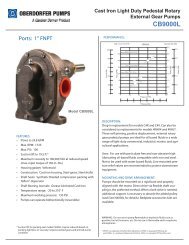
18. TO PRIME, remove plug from<br />
the top of pump case. Fill<br />
piping and pump with water<br />
until the water overflows<br />
from the top of pump case.<br />
Replace plug and tighten to<br />
seal. Install pressure gauge.<br />
Open a faucet or two in the<br />
house. Start motor. If pump<br />
is offset from well 4 feet<br />
or more, it may take a few<br />
minutes for pump to prime.<br />
Failure to prime in 5 minutes: Stop motor, remove<br />
pressure gauge plug from discharge tee, add more<br />
water, try again.<br />
Well Point Pump Installation<br />
Materials nee<strong>de</strong>d in addition to Shallow Well General<br />
Materials, for Well Points only<br />
• Enough galvanized 1-1/4" pipe and drive couplings to<br />
reach from bottom of well to one foot above ground level<br />
• One 1-1/4" galvanized elbow<br />
• One 1-1/4" galvanized nipple<br />
• One 1-1/4" check valve<br />
• One 1-1/4" male PVC adapter<br />
STEP 1: Drive the well point into the ground according to<br />
the instructions inclu<strong>de</strong>d with your well point. Use as much<br />
galvanized pipe and as many drive couplings as it takes to<br />
both reach the water and leave approximately one foot of pipe<br />
protruding from the ground.<br />
STEP 2: Thread 1-1/4" galvanized elbow onto the pipe protruding<br />
from the ground. Seal all pipe threads with Teflon tape.<br />
STEP 3: Thread 1-1/4" galvanized nipple into the 1-1/4"<br />
galvanized elbow.<br />
STEP 4: Thread 1-1/4" check valve onto the 1-1/4"<br />
galvanized nipple.<br />
STEP 5: Thread 1-1/4" male PVC adapter into the 1-1/4"<br />
check valve.<br />
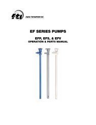
STEP 6: FOLLOW STEPS 6–18 IN SHALLOW CASED WELL<br />
INSTRUCTIONS. Total installation should look like the drawing<br />
below.<br />
FP4155<br />
FP4157<br />
FP4150<br />
FP4205<br />
FP4207,<br />
FP4210<br />
CONVERTIBLE<br />
For parts or assistance, call <strong>Flotec</strong> Customer Service at 1-800-365-6832