Jet Pumps Pompes accélératrices Bombas de chorro - Flotec
Jet Pumps Pompes accélératrices Bombas de chorro - Flotec
Jet Pumps Pompes accélératrices Bombas de chorro - Flotec

You also want an ePaper? Increase the reach of your titles
YUMPU automatically turns print PDFs into web optimized ePapers that Google loves.
Installation 4<br />
Process A. Determine the Depth of<br />
Your Well<br />
Shallow wells are less than 25 feet to water; <strong>de</strong>ep wells are up<br />
to 70 feet to water. Tie a small but heavy weight to the end of<br />
a piece of string (be sure there is enough string; some wells are<br />
very <strong>de</strong>ep). Lower the weight into the well until it reaches the<br />
bottom. Take up the slack and mark the string at ground level.<br />
Pull the weight out of the well and measure from the bottom of<br />
the weight to the ground level mark. This is the <strong>de</strong>pth of your<br />
well. Subtract five feet from the <strong>de</strong>pth of your well. This number<br />
should not exceed the maximum rated <strong>de</strong>pth for your pump. If<br />
it does, it will greatly hin<strong>de</strong>r or prevent the proper operation of<br />
the pump.<br />
Process B. Correctly Select Your Pump<br />
Voltage<br />
Hazardous voltage. Disconnect power to pump<br />
before working on pump or motor. Disconnect pump from<br />
power source before changing the pump voltage. To change the<br />
voltage, the selector switch is located un<strong>de</strong>rneath the plastic<br />
access cover on top of the motor. To access the switch, remove<br />
the eight screws holding the plastic cover. To change the voltage<br />
setting, sli<strong>de</strong> the switch as shown until <strong>de</strong>sired voltage is visible<br />
on the switch. The voltage number that appears is the voltage<br />
setting for the pump. Be sure the switch is completely engaged.<br />
Replace the cover and secure it with the eight screws.<br />
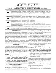
VOLTAGE SELECTION DIRECTIONS<br />
Warning!<br />
Disconnect pump from power<br />
source before servicing or<br />
handling pump.<br />
Be sure that incoming power<br />
supply is same as voltage<br />
selector switch setting.<br />
To change voltage settings<br />
sli<strong>de</strong> switch as shown<br />
until <strong>de</strong>sired voltage is<br />
visible on switch.<br />
Be sure switch is completely<br />
engaged.<br />
Replace capacitor housing cover<br />
and secure cover with screws.<br />
Do not overtighten screws.<br />
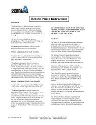
Wiring Your Pump<br />
Hazardous voltage. Disconnect power to pump<br />
before working on pump or motor. Disconnect pump from<br />
power before servicing or handling pump. Remove the cover<br />
from the pressure switch. Connect the bare copper ground to<br />
the ground screw in the pressure switch. Connect the power<br />
supply to the terminals marked “Line" in the diagram below.<br />
Ground<br />
Connections<br />
To Motor<br />
From Line<br />
5907 1108<br />
Piping<br />
Plastic PVC pipe is shown in the illustrations, but galvanized<br />
steel pipe may be used if <strong>de</strong>sired. All piping must be clean and<br />
free of all foreign matter to prevent clogging. ALL JOINTS AND<br />
CONNECTIONS IN THE WELL ASSEMBLY MUST BE AIRTIGHT.<br />
Even a pinhole leak will prevent the proper operation of<br />
the pump (this is the most common problem). Use thread<br />
compound on all threa<strong>de</strong>d joints unless specified otherwise.<br />
Wiring Chart – Recommen<strong>de</strong>d Wire And Fuse Sizes<br />
Distance In Feet(Meters) From Motor To Supply<br />
0 - 100 101 - 200 201 - 300 301 - 400<br />
Motor Nameplate Branch Fuse<br />
(0 - 30) (31 - 61) (62 - 91) (92 - 122)<br />
Mo<strong>de</strong>l HP Volts Amps Rating Amp AWG Wire Size (mm 2 )<br />
FP4155 1/2 115/230 8.5/4.2 15/15 14/14(2/2) 12/14(3/2) 10/14(5.5/2) 8/14(8.4/2)<br />
FP4157 3/4 115/230 11.0/5.5 20/15 12/14(3/2) 10/14(5.5/2) 8/14(8.4/2) 6/14(14/2)<br />
FP4150 1 115/230 12.0/6.0 20/15 12/14(3/2) 10/14(5.5/2) 8/14(8.4/2) 6/14(14/2)<br />
FP4205 1/2 115/230 7.0/3.5 15/15 14/14(2/2) 12/14(3/2) 10/14(5.5/2) 10/14(5.5/2)<br />
FP4207 3/4 115/230 11.0/5.5 20/15 12/14(3/2) 10/14(5.5/2) 8/14(8.4/2) 6/14(14/2)<br />
FP4210 1 115/230 11.0/5.5 20/15 12/14(3/2) 10/14(5.5/2) 8/14(8.4/2) 6/14(14/2)<br />
For parts or assistance, call <strong>Flotec</strong> Customer Service at 1-800-365-6832