Jet Pumps Pompes accélératrices Bombas de chorro - Flotec
Jet Pumps Pompes accélératrices Bombas de chorro - Flotec
Jet Pumps Pompes accélératrices Bombas de chorro - Flotec

Create successful ePaper yourself
Turn your PDF publications into a flip-book with our unique Google optimized e-Paper software.
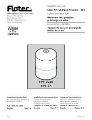
OWNER’S MANUAL<br />
<strong>Jet</strong> <strong>Pumps</strong><br />
293 Wright Street, Delavan, WI 53115<br />
Phone: 1-800-365-6832<br />
Fax: 1-800-526-3757<br />
Web Site: <strong>Flotec</strong>Water.com<br />
NOTICE D’UTILISATION<br />
<strong>Pompes</strong> <strong>accélératrices</strong><br />
MANUAL DEL USUARIO<br />
<strong>Bombas</strong> <strong>de</strong> <strong>chorro</strong><br />
Shallow Well Pump Mo<strong>de</strong>ls<br />
Pompe Pour Puits Peu Profond<br />
Bomba De Pozo Poco Profundo<br />
FP4155 1/2 HP/ch<br />
FP4157 3/4 HP/ch<br />
FP4150 1 HP/ch<br />
Deep Well Pump Mo<strong>de</strong>ls<br />
Pompe Pour Puits Profond<br />
Bomba De Pozo Profundo<br />
FP4205 1/2 HP/ch<br />
FP4207 3/4 HP/ch<br />
FP4210 1 HP/ch<br />
Installation/Operation/Parts<br />
For further operating, installation,<br />
or maintenance assistance:<br />
Call 1-800-365-6832<br />
English . . . . . . . . . . . . . Pages 2-12<br />
Installation/Fonctionnement/<br />
Pièces<br />
Pour plus <strong>de</strong> renseignements<br />
concernant l’utilisation,<br />
l’installation ou l’entretien,<br />
Composer le 1 (800) 365-6832<br />
Français . . . . . . . . . . Pages 13-23<br />
Instalación/Operación/Piezas<br />
Para mayor información sobre el<br />
funcionamiento, instalación o<br />
mantenimiento <strong>de</strong> la bomba:<br />
Llame al 1-800-365-6832<br />
Español. . . . . . . . . . Páginas 24-34<br />
©2011 FP933 (4/5/11)
Safety 2<br />
Important Safety Instructions<br />
SAVE THESE INSTRUCTIONS - This manual contains<br />
important instructions that should be followed during<br />
installation, operation, and maintenance of the product.<br />
Save this manual for future reference.<br />
This is the safety alert symbol. When you see this<br />
symbol on your pump or in this manual, look for one of<br />
the following signal words and be alert to the potential<br />
for personal injury!<br />
indicates a hazard which, if not avoi<strong>de</strong>d, will<br />
result in <strong>de</strong>ath or serious injury.<br />
indicates a hazard which, if not avoi<strong>de</strong>d,<br />
could result in <strong>de</strong>ath or serious injury.<br />
indicates a hazard which, if not avoi<strong>de</strong>d,<br />
could result in minor or mo<strong>de</strong>rate injury.<br />
NOTICE addresses practices not related to personal injury.<br />
Carefully read and follow all safety instructions in this<br />
manual and on pump.<br />
Keep safety labels in good condition.<br />
Replace missing or damaged safety labels.<br />
Electrical Safety<br />
Capacitor voltage may be hazardous.<br />
To discharge motor capacitor, hold insulated handle<br />
screwdriver BY THE HANDLE and short capacitor<br />
terminals together. Do not touch metal screwdriver bla<strong>de</strong><br />
or capacitor terminals. If in doubt, consult a qualified<br />
electrician.<br />
General Safety<br />
Do not touch an operating motor. Mo<strong>de</strong>rn<br />
motors are <strong>de</strong>signed to operate at high temperatures. To<br />
avoid burns when servicing pump, allow it to cool for<br />
20 minutes after shut-down before handling.<br />
Do not allow pump or any system component to freeze.<br />
To do so will void warranty.<br />
Pump water only with this pump.<br />
Periodically inspect pump and system components.<br />
Wear safety glasses at all times when working on pumps.<br />
Keep work area clean, uncluttered and properly lighted;<br />
store properly all unused tools and equipment.<br />
Keep visitors at a safe distance from the work areas.<br />
Pump body may explo<strong>de</strong> if used as a<br />
booster pump unless relief valve capable of passing full<br />
pump flow at 75 psi is installed.<br />
WARNING<br />
Hazardous voltage.<br />
Can shock, burn, or<br />
cause <strong>de</strong>ath.<br />
Ground pump before<br />
connecting to power<br />
supply. Disconnect power<br />
before working on pump,<br />
motor or tank.<br />
Wire motor for correct<br />
voltage. See “Electrical”<br />
section of this manual<br />
and motor nameplate.<br />
Ground motor before<br />
connecting to power<br />
supply.<br />
Meet National Electrical<br />
Co<strong>de</strong>, Canadian<br />
Electrical Co<strong>de</strong>, and<br />
local co<strong>de</strong>s for all<br />
wiring.<br />
Follow wiring<br />
instructions in this<br />
manual when<br />
connecting motor to<br />
power lines.<br />
WARNING<br />
Hazardous pressure!<br />
Install pressure relief<br />
valve in discharge pipe.<br />
Release all pressure on<br />
system before working on<br />
any component.<br />
For parts or assistance, call <strong>Flotec</strong> Customer Service at 1-800-365-6832
Warranty 3<br />
Retain Original Receipt For Your Records<br />
Limited Warranty<br />
FLOTEC warrants to the original consumer purchaser (“Purchaser” or “You”) of its products that they are free from <strong>de</strong>fects in material and workmanship<br />
for a period of twelve (12) months from the date of the original consumer purchase.<br />
If, within twelve (12) months from the original consumer purchase, any such product shall prove to be <strong>de</strong>fective, it shall be repaired or replaced at<br />
FLOTEC’s option, subject to the terms and conditions set forth below. The original purchase receipt and product warranty information label are required<br />
to <strong>de</strong>termine warranty eligibility. Eligibility is based on purchase date of original product – not the date of replacement un<strong>de</strong>r warranty. The warranty is<br />
limited to repair or replacement of product only – Purchaser pays all removal, installation, labor, shipping, and inci<strong>de</strong>ntal charges.<br />
For parts or troubleshooting assistance, DO NOT return product to your retail store. Contact FLOTEC Customer Service at 1-800-365-6832.<br />
Claims ma<strong>de</strong> un<strong>de</strong>r this warranty shall be ma<strong>de</strong> by returning the product (except sewage pumps, see below) to the retail outlet where it was purchased<br />
immediately after the discovery of any alleged <strong>de</strong>fect. FLOTEC will subsequently take corrective action as promptly as reasonably possible. No requests<br />
for service will be accepted if received more than 30 days after the warranty expires.<br />
Sewage <strong>Pumps</strong><br />
DO NOT return a sewage pump (that has been installed) to your retail store. Contact FLOTEC Customer Service. Sewage pumps that have seen service<br />
and been removed carry a contamination hazard with them.<br />
If your sewage pump has failed:<br />
• Wear rubber gloves when handling the pump;<br />
• For warranty purposes, return the pump’s cord tag and original receipt of purchase to the retail store;<br />
• Dispose of the pump according to local disposal ordinances.<br />
Exceptions to the Twelve (12) Month Limited Warranty<br />
Product<br />
Drill Pump, Pitcher Pump, In-line Water Filter Cartridge, Utility Pump (Mo<strong>de</strong>l FP0F360AC, FP0FDC)<br />
1/3 HP Submersible Sump <strong>Pumps</strong>, Pool Cover Pump (Mo<strong>de</strong>l FP0S1790PCA), Utility Pump (Mo<strong>de</strong>l FP0S4100X), Con<strong>de</strong>nsate<br />
Pump (Mo<strong>de</strong>l FPCP-20ULST), IntelliPump (Mo<strong>de</strong>l FP0S1775A), Back-up Sump Pump System (Mo<strong>de</strong>l FP2800DCC)<br />
Warranty Period<br />
General Terms and Conditions<br />
You must pay all labor and shipping charges necessary to replace product covered by this warranty. This warranty does not apply to the following:<br />
(1) acts of God; (2) products which, in FLOTEC’s sole judgement, have been subject to negligence, abuse, acci<strong>de</strong>nt, misapplication, tampering, or<br />
alteration; (3) failures due to improper installation, operation, maintenance or storage; (4) atypical or unapproved application, use or service; (5) failures<br />
caused by corrosion, rust or other foreign materials in the system, or operation at pressures in excess of recommen<strong>de</strong>d maximums.<br />
This warranty sets forth FLOTEC’s sole obligation and purchaser’s exclusive remedy for <strong>de</strong>fective products.<br />
FLOTEC SHALL NOT BE LIABLE FOR ANY CONSEQUENTIAL, INCIDENTAL, OR CONTINGENT DAMAGES WHATSOEVER.<br />
THE FOREGOING WARRANTIES ARE EXCLUSIVE AND IN LIEU OF ALL OTHER EXPRESS AND IMPLIED WARRANTIES, INCLUDING BUT NOT LIMITED<br />
TO THE IMPLIED WARRANTIES OF MERCHANTABILITY AND FITNESS FOR A PARTICULAR PURPOSE. THE FOREGOING WARRANTIES SHALL NOT<br />
EXTEND BEYOND THE DURATION PROVIDED HEREIN.<br />
Some states do not allow the exclusion or limitation of inci<strong>de</strong>ntal or consequential damages or limitations on how long an implied warranty lasts, so the<br />
above limitations or exclusions may not apply to You. This warranty gives You specific legal rights and You may also have other rights which vary from<br />
state to state.<br />
FLOTEC • 293 Wright Street • Delavan, WI U.S.A. 53115<br />
Phone: 1-800-365-6832 • Fax: 1-800-526-3757<br />
Web Site: <strong>Flotec</strong>Water.com<br />
90 days<br />
2 Years<br />
4” Submersible Well <strong>Pumps</strong>, 1/2 HP Submersible Sump <strong>Pumps</strong>, 1/3 HP Sump Pump Mo<strong>de</strong>ls (FPSC2200A-10, FPSC2250A-10) 3 Years<br />
Pre-Charge Water System Tank (FP7100 Series), 1/2 HP Sump Pump (Mo<strong>de</strong>ls FPSC3200A-10, FPSC3250A-10), Submersible<br />
Solids Handling <strong>Pumps</strong> (Mo<strong>de</strong>ls FPSE9000, E75STVT), Submersible Sump <strong>Pumps</strong> (Mo<strong>de</strong>ls E50TLT, E50VLT, E75VLT,<br />
E100ELT, FPSC5000A)<br />
Floodmate® 7000 (Mo<strong>de</strong>l FP0S6000A), Pe<strong>de</strong>stal Sump Pump (Mo<strong>de</strong>l FPPSS5000), Sewage Ejector (Mo<strong>de</strong>l FPSE3601A),<br />
Submersible Sewage Pump (Mo<strong>de</strong>l FPSES2700A), Utility Pump (Mo<strong>de</strong>l FPSC1725X), Submersible Sump Pump (Mo<strong>de</strong>l<br />
FPSC4550A-10)<br />
5 Years<br />
Lifetime<br />
For parts or assistance, call <strong>Flotec</strong> Customer Service at 1-800-365-6832
Installation 4<br />
Process A. Determine the Depth of<br />
Your Well<br />
Shallow wells are less than 25 feet to water; <strong>de</strong>ep wells are up<br />
to 70 feet to water. Tie a small but heavy weight to the end of<br />
a piece of string (be sure there is enough string; some wells are<br />
very <strong>de</strong>ep). Lower the weight into the well until it reaches the<br />
bottom. Take up the slack and mark the string at ground level.<br />
Pull the weight out of the well and measure from the bottom of<br />
the weight to the ground level mark. This is the <strong>de</strong>pth of your<br />
well. Subtract five feet from the <strong>de</strong>pth of your well. This number<br />
should not exceed the maximum rated <strong>de</strong>pth for your pump. If<br />
it does, it will greatly hin<strong>de</strong>r or prevent the proper operation of<br />
the pump.<br />
Process B. Correctly Select Your Pump<br />
Voltage<br />
Hazardous voltage. Disconnect power to pump<br />
before working on pump or motor. Disconnect pump from<br />
power source before changing the pump voltage. To change the<br />
voltage, the selector switch is located un<strong>de</strong>rneath the plastic<br />
access cover on top of the motor. To access the switch, remove<br />
the eight screws holding the plastic cover. To change the voltage<br />
setting, sli<strong>de</strong> the switch as shown until <strong>de</strong>sired voltage is visible<br />
on the switch. The voltage number that appears is the voltage<br />
setting for the pump. Be sure the switch is completely engaged.<br />
Replace the cover and secure it with the eight screws.<br />
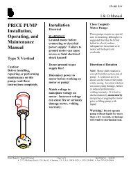
VOLTAGE SELECTION DIRECTIONS<br />
Warning!<br />
Disconnect pump from power<br />
source before servicing or<br />
handling pump.<br />
Be sure that incoming power<br />
supply is same as voltage<br />
selector switch setting.<br />
To change voltage settings<br />
sli<strong>de</strong> switch as shown<br />
until <strong>de</strong>sired voltage is<br />
visible on switch.<br />
Be sure switch is completely<br />
engaged.<br />
Replace capacitor housing cover<br />
and secure cover with screws.<br />
Do not overtighten screws.<br />
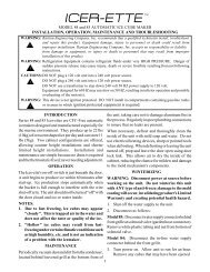
Wiring Your Pump<br />
Hazardous voltage. Disconnect power to pump<br />
before working on pump or motor. Disconnect pump from<br />
power before servicing or handling pump. Remove the cover<br />
from the pressure switch. Connect the bare copper ground to<br />
the ground screw in the pressure switch. Connect the power<br />
supply to the terminals marked “Line" in the diagram below.<br />
Ground<br />
Connections<br />
To Motor<br />
From Line<br />
5907 1108<br />
Piping<br />
Plastic PVC pipe is shown in the illustrations, but galvanized<br />
steel pipe may be used if <strong>de</strong>sired. All piping must be clean and<br />
free of all foreign matter to prevent clogging. ALL JOINTS AND<br />
CONNECTIONS IN THE WELL ASSEMBLY MUST BE AIRTIGHT.<br />
Even a pinhole leak will prevent the proper operation of<br />
the pump (this is the most common problem). Use thread<br />
compound on all threa<strong>de</strong>d joints unless specified otherwise.<br />
Wiring Chart – Recommen<strong>de</strong>d Wire And Fuse Sizes<br />
Distance In Feet(Meters) From Motor To Supply<br />
0 - 100 101 - 200 201 - 300 301 - 400<br />
Motor Nameplate Branch Fuse<br />
(0 - 30) (31 - 61) (62 - 91) (92 - 122)<br />
Mo<strong>de</strong>l HP Volts Amps Rating Amp AWG Wire Size (mm 2 )<br />
FP4155 1/2 115/230 8.5/4.2 15/15 14/14(2/2) 12/14(3/2) 10/14(5.5/2) 8/14(8.4/2)<br />
FP4157 3/4 115/230 11.0/5.5 20/15 12/14(3/2) 10/14(5.5/2) 8/14(8.4/2) 6/14(14/2)<br />
FP4150 1 115/230 12.0/6.0 20/15 12/14(3/2) 10/14(5.5/2) 8/14(8.4/2) 6/14(14/2)<br />
FP4205 1/2 115/230 7.0/3.5 15/15 14/14(2/2) 12/14(3/2) 10/14(5.5/2) 10/14(5.5/2)<br />
FP4207 3/4 115/230 11.0/5.5 20/15 12/14(3/2) 10/14(5.5/2) 8/14(8.4/2) 6/14(14/2)<br />
FP4210 1 115/230 11.0/5.5 20/15 12/14(3/2) 10/14(5.5/2) 8/14(8.4/2) 6/14(14/2)<br />
For parts or assistance, call <strong>Flotec</strong> Customer Service at 1-800-365-6832
Installation 5<br />
Process C. 1. Install a shallow well pump<br />
(FP4155, FP4157, FP4150)<br />
Draining For Servicing or For Winter<br />
The pump should be drained before it is disconnected for<br />
servicing or if it is in danger of freezing. To drain:<br />
• Remove drain plug from bottom of pump case.<br />
• Remove discharge tee to vent the pump.<br />
• Drain all piping to a point 3 feet (1 meter) below<br />
ground level.<br />
For wells 25 feet or less in <strong>de</strong>pth, the 1/2 HP FP4155, 3/4 HP<br />
FP4157 and 1 HP FP4150 pumps are recommen<strong>de</strong>d. However,<br />
the 1/2 HP FP4205, 3/4 HP FP4207, and 1 HP FP4210<br />
convertible pumps may be adapted to shallow wells with an<br />
ejector kit.<br />
General Materials Required<br />
• One can PVC cement (read instructions carefully)<br />
• One can thread compound (read instructions carefully)<br />
• One 1-1/4" foot valve<br />
• Two male 1-1/4" PVC adapters<br />
• Enough rigid 1-1/4" PVC pipe and couplings to reach from<br />
bottom of well to pump<br />
• One well seal with vent plug<br />
• One 1-1/4" PVC elbow<br />
• One discharge tee<br />
• One pressure gauge<br />
• One male 1" PVC adapter<br />
• Enough rigid 1" PVC pipe to reach from pump to pressure<br />
tank to service line<br />
• One female 1" PVC adapter<br />
• One 1" tank cross (for diaphragm tanks)<br />
• Two 1/4" plugs<br />
• One 1/2" drain cock<br />
• One 10" x 1" nipple<br />
In addition to General Materials, for the FP4205,<br />
FP4207, or FP4210 Convertible only<br />
One ejector kit; inclu<strong>de</strong>s ejector, venturi tube, gasket, bolts,<br />
plug, tubing, and fittings.<br />
Tools nee<strong>de</strong>d for all pump installations<br />
Pipe wrench, pipe clamp, crescent wrench, slot screwdriver,<br />
24-tooth hacksaw, knife or round file.<br />
Remin<strong>de</strong>r: All joints and connections must be airtight. A single pinhole leak will prevent the<br />
proper operation of the pump. Use thread compound on all threa<strong>de</strong>d connections unless<br />
specified otherwise.<br />
1. Thread 1-1/4" male PVC<br />
adapter into foot valve. Hand<br />
tighten, then tighten 1/4 turn<br />
with crescent wrench. Seal<br />
the threa<strong>de</strong>d pipe joints with<br />
1<br />
Teflon tape or Teflon<br />
based pipe joint compound<br />
approved for use on PVC.<br />
1<br />
E. I. DuPont <strong>de</strong> Demours and Company<br />
Corporation, Delaware<br />
1-1/4"<br />
MALE PVC<br />
ADAPTER<br />
FOOT<br />
VALVE<br />
3. Cement as many couplings and<br />
sections of rigid PVC pipe as it<br />
takes to equal the <strong>de</strong>pth of your<br />
well minus five feet, then firmly<br />
clamp the assembly with a pipe<br />
clamp to prevent the assembly<br />
from sliding down into the well.<br />
2. Subtract five feet from the <strong>de</strong>pth of<br />
your well (see page 2 “Determine<br />
the Depth of Your Well"). This is<br />
the total length of rigid PVC pipe<br />
and couplings to cement onto the<br />
1-1/4" male PVC adapter. Cement<br />
one section of rigid PVC pipe to the<br />
PVC adapter which is connected<br />
to the foot valve, then lower the<br />
whole assembly into the well, foot<br />
valve first. Firmly clamp the end<br />
of the rigid PVC pipe with a pipe<br />
clamp to prevent the assembly<br />
from sliding down into the well.<br />
PVC<br />
P PE<br />
SECTION<br />
1-1/4"<br />
MALE PVC<br />
ADAPTER<br />
FOOT<br />
VALVE<br />
For parts or assistance, call <strong>Flotec</strong> Customer Service at 1-800-365-6832
Installation 6<br />
Process C, continued.<br />
4. HOLD THE PIPE, remove pipe clamp<br />
and sli<strong>de</strong> well seal over rigid PVC<br />
pipe and onto well casing. Position<br />
assembly so that twelve inches of<br />
rigid PVC pipe protru<strong>de</strong> from well<br />
seal. Alternately turn bolts on well<br />
seal clockwise until rubber gaskets<br />
are tight against well casing and rigid<br />
PVC pipe.<br />
5. Cement 1-1/4" PVC elbow onto<br />
rigid PVC pipe protruding from well<br />
seal. If <strong>de</strong>sired, some length may<br />
be cut off of rigid PVC pipe before<br />
cementing elbow. Smooth the insi<strong>de</strong><br />
of any rigid PVC pipe that has been<br />
cut with a round file or knife.<br />
6. If you are using the FP4155, FP4157,<br />
BUSHING<br />
or FP4150 pump, thread a 1-1/4"<br />
male PVC adapter into the front of it.<br />
Hand tighten, then turn 1/4 turn with<br />
crescent wrench. Seal the threa<strong>de</strong>d<br />
pipe joints with Teflon tape or<br />
Teflon based pipe joint compound approved for<br />
use on PVC.<br />
7. Open ejector kit.<br />
Gasket<br />
Replace nozzle #3<br />
Venturi tube<br />
with nozzle #2 (from<br />
Nozzle<br />
kit) and tighten until<br />
snug. Thread shorter<br />
venturi tube into<br />
ejector until snug.<br />
Place gasket over<br />
venturi tube so that<br />
openings in gasket line up with openings in ejector.<br />
8. Sli<strong>de</strong> bolts through the bolt openings<br />
on either si<strong>de</strong> of the ejector, through<br />
the gasket and bolt ejector to front of<br />
the pump. Tighten bolts securely.<br />
APPROX.<br />
12" OF<br />
PVC PIPE<br />
PROTRUDING<br />
FROM WELL<br />
SEAL<br />
WELL<br />
SEAL<br />
1-1/4"<br />
PVC<br />
ELBOW<br />
TOP OF<br />
PVC PIPE<br />
PROTRUDING<br />
FROM WELL<br />
SEAL<br />
1-1/4"<br />
MALE PVC<br />
ADAPTER<br />
PUMP<br />
Priming Shallow Well <strong>Jet</strong> <strong>Pumps</strong><br />
Steps 7–12 are for FP4205, FP4207, and FP4210<br />
convertible pumps. See kit instruction sheet.<br />
Ejector<br />
Bolts<br />
6391 0211<br />
BOLT<br />
EJECTOR<br />
10. Cement<br />
as many<br />
1-1/4" PVC PIPE<br />
sections and<br />
couplings<br />
of PVC pipe<br />
nee<strong>de</strong>d to<br />
connect the<br />
PVC elbow to the 1-1/4" male PVC adapter in the front of<br />
the pump.<br />
11. Apply 2-3 wraps of Teflon tape to<br />
the male threads on the discharge<br />
tee. Using pipe wrench, thread 1"<br />
discharge tee into top of pump.<br />
Remove pressure gauge plug from<br />
top of discharge tee. TO PRIME: Put<br />
a gar<strong>de</strong>n hose into top of discharge<br />
tee and fill pipes and pump until water overflows<br />
from top of discharge tee. This may take several<br />
minutes.<br />
12. Thread pressure gauge and plug<br />
into discharge tee. Make sure all<br />
connections are tightly sealed.<br />
PRESSURE<br />
GAUGE<br />
PLUG<br />
DISCHARGE<br />
TEE<br />
PRESSURE<br />
GAUGE<br />
13. Complete all electrical connections as <strong>de</strong>scribed on page 4.<br />
Sealing Pipe Joints<br />
Use only Teflon tape or Teflon based joint compounds<br />
for making all threa<strong>de</strong>d connections to the pump itself. Do<br />
not use pipe joint compounds on plastic pumps: they can<br />
react with the plastic in pump components. Make sure that<br />
all pipe joints in the suction pipe are air tight as well as<br />
water tight. If the suction pipe can suck air, the pump will<br />
not be able to pull water from the well.<br />
14. Screw 1" male PVC adapter<br />
into discharge tee outlet.<br />
15. Thread 10" x 1" nipple into<br />
pressure tank. Thread tank<br />
cross into nipple so that the<br />
two 1/4" holes in tank cross<br />
face upward. Plug two outlets<br />
on tank cross with two 1/4"<br />
plugs.<br />
NIPPLE<br />
1" MALE PVC<br />
ADAPTER<br />
1/4" PLUGS<br />
TANK<br />
CROSS<br />
9. Thread a 1-1/4" male PVC adapter<br />
into front of ejector. Hand tighten,<br />
then turn 1/4 turn with wrench.<br />
Seal the threa<strong>de</strong>d pipe joints with<br />
Teflon tape or Teflon based pipe<br />
joint compound approved for use<br />
on PVC.<br />
1-1/4"<br />
MALE PVC<br />
ADAPTER<br />
16. Thread 1/2" boiler drain into<br />
front of tank cross. Thread 1"<br />
male PVC adapter into inlet<br />
si<strong>de</strong> of tank cross. Connect to<br />
household plumbing.<br />
1" MALE<br />
PVC ADAPTER<br />
1/2"<br />
BOILER<br />
DRAIN<br />
For parts or assistance, call <strong>Flotec</strong> Customer Service at 1-800-365-6832
Installation 7<br />
Process C, continued.<br />
17. Cement as many sections and couplings of rigid 1" PVC<br />
pipe nee<strong>de</strong>d to connect the 1" male PVC adapter in the<br />
discharge tee to the 1" male adapter on the tank cross inlet.<br />
Set pressure in the pre-charged pressure tank to<br />
2 pounds less than the cut-in pressure of the pump. The<br />
cut-in pressure of these pumps is factory preset to 30 PSI. If<br />
this cut-in setting has not been changed, then the precharged<br />
pressure tank should be set to 28 PSI. Total<br />
installation should look like the shallow well drawing<br />
below.<br />
18. TO PRIME, remove plug from<br />
the top of pump case. Fill<br />
piping and pump with water<br />
until the water overflows<br />
from the top of pump case.<br />
Replace plug and tighten to<br />
seal. Install pressure gauge.<br />
Open a faucet or two in the<br />
house. Start motor. If pump<br />
is offset from well 4 feet<br />
or more, it may take a few<br />
minutes for pump to prime.<br />
Failure to prime in 5 minutes: Stop motor, remove<br />
pressure gauge plug from discharge tee, add more<br />
water, try again.<br />
Well Point Pump Installation<br />
Materials nee<strong>de</strong>d in addition to Shallow Well General<br />
Materials, for Well Points only<br />
• Enough galvanized 1-1/4" pipe and drive couplings to<br />
reach from bottom of well to one foot above ground level<br />
• One 1-1/4" galvanized elbow<br />
• One 1-1/4" galvanized nipple<br />
• One 1-1/4" check valve<br />
• One 1-1/4" male PVC adapter<br />
STEP 1: Drive the well point into the ground according to<br />
the instructions inclu<strong>de</strong>d with your well point. Use as much<br />
galvanized pipe and as many drive couplings as it takes to<br />
both reach the water and leave approximately one foot of pipe<br />
protruding from the ground.<br />
STEP 2: Thread 1-1/4" galvanized elbow onto the pipe protruding<br />
from the ground. Seal all pipe threads with Teflon tape.<br />
STEP 3: Thread 1-1/4" galvanized nipple into the 1-1/4"<br />
galvanized elbow.<br />
STEP 4: Thread 1-1/4" check valve onto the 1-1/4"<br />
galvanized nipple.<br />
STEP 5: Thread 1-1/4" male PVC adapter into the 1-1/4"<br />
check valve.<br />
STEP 6: FOLLOW STEPS 6–18 IN SHALLOW CASED WELL<br />
INSTRUCTIONS. Total installation should look like the drawing<br />
below.<br />
FP4155<br />
FP4157<br />
FP4150<br />
FP4205<br />
FP4207,<br />
FP4210<br />
CONVERTIBLE<br />
For parts or assistance, call <strong>Flotec</strong> Customer Service at 1-800-365-6832
Installation 8<br />
Process C. 2. Install a <strong>de</strong>ep well pump<br />
(FP4205, FP4207, FP4210)<br />
Deep Well Pump Installation<br />
(4" or Larger Diameter Cased Well)<br />
For wells over 25, but not exceeding 70 feet in <strong>de</strong>pth, the<br />
1 HP Convertible Deep Well Pump is recommen<strong>de</strong>d. However,<br />
the 1/2 HP or 3/4 HP Deep Well Pump may also be used for<br />
<strong>de</strong>pths not exceeding 70 feet.<br />
General materials nee<strong>de</strong>d for the convertible pumps:<br />
• One can PVC cement (read instructions carefully)<br />
• One can thread compound (read instructions carefully)<br />
• Two 1" female PVC adapters<br />
• Enough rigid 1-1/4" and 1" PVC pipe and couplings to<br />
reach from bottom of well to pump (<strong>de</strong>livery pipe)<br />
• One 1-1/4" PVC elbow<br />
• One 1-1/4" male PVC adapter<br />
• One pressure regulator Kit (inclu<strong>de</strong>s fittings, tubing, and<br />
1/4" plug)<br />
• One pressure gauge<br />
• Two male 3/4" PVC adapters<br />
• Enough rigid 3/4" PVC pipe to reach from pump to pressure<br />
tank to service line<br />
• Tank tee (for diaphragm pressure tanks)<br />
• Two 1/4" plugs<br />
• One 1/2" drain cock<br />
In addition to General Materials for Deep Well <strong>Pumps</strong><br />
• One 1-1/4" foot valve<br />
• One 1-1/4" close nipple<br />
• One ejector<br />
• One 1" x 5" nipple<br />
• One 1-1/4" female adapter<br />
• One well seal<br />
• Enough rigid 1" PVC pipe and couplings to reach from<br />
bottom of well to pump (pressure pipe)<br />
• One 1" PVC elbow<br />
• Two 1-1/4" male PVC adapters<br />
• One 1" x 4" nipple<br />
Remin<strong>de</strong>r: All joints and connections must be airtight. A single pinhole leak will prevent the<br />
proper operation of the pump. Use thread compound on all threa<strong>de</strong>d connections unless<br />
specified otherwise.<br />
To Install A Convertible <strong>Jet</strong> Pump:<br />
1. Thread 1-1/4" close nipple into foot<br />
valve. Thread the other end of 1-1/4"<br />
close nipple into bottom of <strong>de</strong>ep well<br />
ejector. Hand tighten, then tighten<br />
1/4 turn with pipe wrench.<br />
2. The ejector has two holes in the top<br />
of it. Confirm nozzle is installed.<br />
Thread <strong>de</strong>ep well venturi tube (longer<br />
tube) into larger hole until snug.<br />
Thread 1" x 5" nipple into smaller<br />
hole. Only hand tighten venturi tube.<br />
Hand tighten nipple 1/4 turn with<br />
pipe/crescent wrench.<br />
EJECTOR<br />
1-1/4"<br />
CLOSE<br />
NIPPLE<br />
FOOT<br />
VALVE<br />
1" x 5"<br />
Nipple<br />
Venturi<br />
Nozzle<br />
Ejector<br />
3. Thread a 1-1/4" male PVC adapter<br />
over the venturi tube and into<br />
ejector. Thread a 1" female PVC<br />
adapter onto the 1" x 5" nipple.<br />
Hand tighten adapters 1/4 turn with<br />
pipe/crescent wrench.<br />
4. Subtract five feet from the <strong>de</strong>pth of<br />
your well. This is the total length<br />
of PVC pipe and couplings to<br />
cement onto both 1-1/4" male and<br />
1" female PVC adapters. Cement<br />
a section of PVC pipe to each<br />
adapter, then lower the whole<br />
assembly into the well, foot valve<br />
first. Firmly clamp the end of the<br />
1" FEMALE<br />
PVC<br />
ADAPTER<br />
1" FEMALE<br />
PVC<br />
ADAPTER<br />
1-1/4" MALE<br />
PVC<br />
ADAPTER<br />
1-1/4" MALE<br />
PVC<br />
ADAPTER<br />
PVC pipes with a pipe clamp to prevent the assembly from<br />
sliding down into well.<br />
6392 0211<br />
For parts or assistance, call <strong>Flotec</strong> Customer Service at 1-800-365-6832
Installation 9<br />
Process C, continued.<br />
5. Cement as many couplings and<br />
sections of rigid PVC pipe on both<br />
the pressure and <strong>de</strong>livery si<strong>de</strong>s as it<br />
takes to equal the <strong>de</strong>pth of your well<br />
minus four feet, then firmly clamp the<br />
assembly with a pipe clamp to prevent<br />
the assembly from sliding down into<br />
the well. Be sure to keep track of<br />
which pipe is the pressure pipe and<br />
which is the <strong>de</strong>livery pipe.<br />
10. Open pressure regulator kit.<br />
Apply 2-3 wraps of Teflon tape<br />
to the male threads on the body<br />
of the pressure regulator. With<br />
pipe wrench, thread the pressure<br />
regulator into 1" discharge at top of<br />
pump. Thread pressure gauge into si<strong>de</strong> of pump case.<br />
11. Thread plug into opening to right of<br />
pressure regulator outlet.<br />
PRESSURE<br />
REGULATOR<br />
PRESSURE<br />
REGULATOR<br />
OUTLET<br />
PLUG<br />
6. Remove pipe clamp and sli<strong>de</strong> well<br />
seal over PVC pipes and onto well<br />
casing. DO NOT let assembly sli<strong>de</strong><br />
down into well. Position assembly<br />
so that twelve inches of PVC pipes<br />
protru<strong>de</strong> from well seal. Using<br />
crescent wrench, turn bolts on well<br />
seal clockwise until rubber gaskets are<br />
tight against the well casing and the<br />
PVC pipes.<br />
7. Cut 1" pipe 2" shorter than the<br />
1-1/4" pipe. Smooth rough<br />
edges. Cement 1" and 1-1/4"<br />
PVC elbows to pipes protruding from<br />
the well seal.<br />
12" OF<br />
PVC PIPE<br />
PROTRUD-<br />
ING FROM<br />
WELL<br />
SEAL<br />
WELL SEAL<br />
1-1/4" PVC<br />
ELBOW<br />
1" PVC<br />
ELBOW<br />
1" PIPE 2"<br />
SHORTER<br />
THAN 1-1/4"<br />
PIPE<br />
Priming Deep Well <strong>Jet</strong> <strong>Pumps</strong><br />
12. Complete all electrical connections as <strong>de</strong>scribed on page 4.<br />
Sealing Pipe Joints<br />
Use only Teflon tape or Teflon based joint compounds<br />
for making all threa<strong>de</strong>d connections to the pump itself. Do<br />
not use pipe joint compounds on plastic pumps: they can<br />
react with the plastic in pump components. Make sure that<br />
all pipe joints in the suction pipe are air tight as well as<br />
water tight. If the suction pipe can suck air, the pump will<br />
not be able to pull water from the well.<br />
13. Thread 3/4" male PVC adapter<br />
into pressure regulator outlet.<br />
14. Thread tank tee into<br />
pre-charged pressure tank.<br />
Plug two outlets on tank tee<br />
with two 1/4" plugs.<br />
TANK TEE<br />
3/4" MALE<br />
PVC ADAPTER<br />
1/4" PLUGS<br />
8. Thread a 1-1/4" male PVC adapter<br />
into top hole in front of pump.<br />
Thread 1" x 4" nipple into bottom<br />
hole in front of pump. Thread the<br />
1" female PVC adapter onto the<br />
1" x 4" nipple. Seal the threa<strong>de</strong>d<br />
1-1/4" MALE<br />
PVC ADAPTER<br />
1" FEMALE<br />
PVC<br />
ADAPTER<br />
1" x 4"<br />
NIPPLE<br />
pipe joints with Teflon tape or Teflon based pipe joint<br />
compound approved for use on PVC.<br />
9. Cement<br />
1-1/4" PVC P PE<br />
as many<br />
sections<br />
and<br />
couplings<br />
FEMALE ADAPTER<br />
of rigid 1"<br />
and 1-1/4"<br />
PVC as<br />
nee<strong>de</strong>d to connect the 1" female PVC adapter and the<br />
1-1/4" male PVC adapter to the 1" and 1-1/4" PVC elbows.<br />
1" PVC P PE<br />
15. Thread boiler drain into<br />
front of tank tee. Thread<br />
3/4" male PVC adapter into inlet<br />
si<strong>de</strong> of tank tee. Connect to<br />
household plumbing.<br />
3/4" MALE<br />
PVC<br />
ADAPTER<br />
1/2" BOILER<br />
DRAIN<br />
16. TO PRIME: Remove<br />
pressure regulator, put a<br />
gar<strong>de</strong>n hose into the top<br />
of the pump discharge<br />
and fill and pump<br />
with water until water<br />
overflows from top of<br />
pump. This may take several minutes. Put regulator back<br />
on pump.<br />
For parts or assistance, call <strong>Flotec</strong> Customer Service at 1-800-365-6832
Installation 10<br />
Process C, continued.<br />
17. Cement as many sections and couplings of rigid 3/4" PVC<br />
pipe nee<strong>de</strong>d to connect the 3/4" PVC adapter in the<br />
discharge tee to the 3/4" male adapter on the tank tee inlet.<br />
Set pressure in the diaphragm pressure tank to<br />
2 pounds less than the cut-in pressure of the pump. The<br />
cut-in pressure of these pumps is factory preset to 30 PSI. If<br />
this cut-in setting has not been changed, then the diaphragm<br />
pressure tank should be set to 28 PSI. Total installation<br />
should look like the drawing at right.<br />
Risk of explosion. If you change pressure<br />
switch settings, set the cut-off pressure low enough to<br />
shut off the pump. If a valve shuts off and the cut-off<br />
setting is too high, the pump will run continuously<br />
without water flow, causing overheating and possible<br />
explosion which can cause serious burns and damage.<br />
18. Open a faucet or two in<br />
the house. Turn regulator<br />
adjustment screw down<br />
tight. Start motor. If pump<br />
is properly primed, a high<br />
pressure will immediately<br />
show on the pressure gauge.<br />
With pump operating at high<br />
pressure, slowly unscrew<br />
regulator stem until maximum<br />
water flow is obtained without<br />
REGULATOR<br />
STEM<br />
dropping to zero. If pressure falls completely, retighten stem<br />
and readjust. Steady pressure must not be less than<br />
24 PSI for the FP4205 and 32 PSI for the FP4210. If no<br />
pressure shows, stop motor, remove pressure regulator from<br />
pump, add more water, and try again.<br />
If you install your pump with a 2" single-pipe<br />
(“Packer”) jet, please follow the installation<br />
instructions inclu<strong>de</strong>d with the Packer jet kit.<br />
NOTICE: Plastic shipping fixture is used to prevent movement in shipment only.<br />
Do not return pump if shipping fixture becomes cracked, as pump performance<br />
will not be affected.<br />
For parts or assistance, call <strong>Flotec</strong> Customer Service at 1-800-365-6832
Troubleshooting 11<br />
Symptom Possible Cause(s) Corrective Action<br />
Motor will not run Disconnect switch is off Be sure switch is on.<br />
Fuse is blown or circuit breaker tripped Replace fuse or reset circuit breaker.<br />
Starting switch is <strong>de</strong>fective<br />
DISCONNECT POWER; Replace starting switch.<br />
Wires at motor are loose, disconnected, or<br />
wired incorrectly<br />
Refer to instructions on wiring (Page 9). DISCONNECT POWER; check and<br />
tighten all wiring.<br />
Capacitor voltage may be hazardous. To discharge capacitor,<br />
hold insulated handle screwdriver BY THE HANDLE and short capacitor<br />
terminals together. Do not touch metal screwdriver bla<strong>de</strong> or capacitor terminals.<br />
If in doubt, consult a qualified electrician.<br />
Pressure switch contacts are dirty<br />
DISCONNECT POWER and file contacts with emery board or nail file.<br />
Motor runs hot and overload Motor is wired incorrectly<br />
Refer to instructions on wiring.<br />
kicks off<br />
Voltage is too low<br />
Check with power company. Install heavier wiring if wire size is too small (See<br />
Electrical / Wiring Chart).<br />
Pump cycles too frequently<br />
See section below on too frequent cycling.<br />
Motor runs but no water is<br />
<strong>de</strong>livered*<br />
* Stop pump; then check<br />
Pump in new installation did not pick up<br />
prime through:<br />
1. Improper priming<br />
2. Air leaks<br />
3. Leaking foot valve or check valve<br />
In new installation:<br />
1. Re-prime according to instructions.<br />
2. Check all connections on suction line, AVC, and ejector with soapy water or<br />
shaving cream.<br />
3. Replace foot valve or check valve.<br />
prime before looking for<br />
Pump has lost prime through:<br />
In installation already in use:<br />
other causes. Unscrew<br />
priming plug and see if<br />
1. Air leaks<br />
1. Check all connections on suction line and shaft seal.<br />
water is in priming hole. 2. Water level below suction pipe inlet 2. Lower suction line into water and re-prime. If receding water level in well<br />
exceeds 25’ (7.6M), a <strong>de</strong>ep well pump is nee<strong>de</strong>d.<br />
Foot valve or strainer is plugged<br />
Clean foot valve or strainer.<br />
Ejector or impeller is plugged<br />
Clean ejector or impeller.<br />
Check valve or foot valve is stuck shut Replace check valve or foot valve.<br />
Pipes are frozen<br />
Thaw pipes. Bury pipes below frost line. Heat pit or pump house.<br />
Foot valve and/or strainer are buried in<br />
sand or mud<br />
Raise foot valve and/or strainer above bottom of water source. Clean foot valve<br />
and strainer.<br />
Water level is too low for shallow well<br />
setup to <strong>de</strong>liver water<br />
A <strong>de</strong>ep well jet will be nee<strong>de</strong>d if your well is more than 25’ (7.6M) <strong>de</strong>pth to<br />
water.<br />
Pump does not <strong>de</strong>liver water Water level in well is lower than estimated A new nozzle and venturi combination may be nee<strong>de</strong>d.<br />
to full capacity (Also check<br />
Steel piping (if used) is corro<strong>de</strong>d or limed,<br />
point 3 immediately above)<br />
causing excess friction<br />
Replace with plastic pipe where possible, otherwise with new steel pipe.<br />
Piping is too small in size<br />
Use larger piping.<br />
Pump <strong>de</strong>livers water but does Pressure switch is out of adjustment or DISCONNECT POWER; adjust or replace pressure switch.<br />
not shut off or pump cycles<br />
too frequently<br />
contacts are wel<strong>de</strong>d together<br />
Faucets have been left open<br />
Close faucets.<br />
Venturi, nozzle or impeller is clogged Clean venturi, nozzle or impeller.<br />
Standard pressure tank is waterlogged and<br />
has no air cushion<br />
Drain tank to air volume control port. Check AVC for <strong>de</strong>fects. Check all<br />
connections for air leaks.<br />
Pipes leak<br />
Check connections.<br />
Foot valve leaks<br />
Replace foot valve.<br />
Pressure switch is out of adjustment Adjust or replace pressure switch.<br />
Air charge too low in pre-charged tank DISCONNECT POWER and open faucets until all pressure is relieved. Using<br />
tire pressure gauge, check air pressure in tank at valve stem located on the tank.<br />
If less than pressure switch cut-in setting (30-50 PSI), pump air into tank from<br />
outsi<strong>de</strong> source until air pressure is 2 PSI less than cut-in setting of switch. Check<br />
air valve for leaks (use soapy solution) and replace core if necessary.<br />
Air spurts from faucets Pump is picking up prime When pump has picked up prime, it should pump solid water with no air.<br />
Leak in suction si<strong>de</strong> of pump<br />
Suction pipe is sucking air. Check joints for leaks with soapy water.<br />
Well is gaseous<br />
Consult factory about installing a sleeve in the well.<br />
Intermittent over-pumping of well. (Water<br />
drawn down below foot valve.)<br />
Lower foot valve if possible, otherwise restrict pump discharge.<br />
For parts or assistance, call <strong>Flotec</strong> Customer Service at 1-800-365-6832
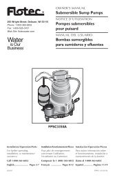
Repair Parts 12<br />
1A<br />
1<br />
2 3<br />
4<br />
5<br />
6<br />
7<br />
8<br />
9<br />
10<br />
11<br />
12<br />
13<br />
14<br />
15<br />
Shallow Well<br />
6<br />
9<br />
11 10 12<br />
15<br />
15A<br />
6<br />
13<br />
Deep Well<br />
16<br />
14 17<br />
18<br />
19<br />
5912 1108<br />
Key Part<br />
No. Description<br />
Qty.<br />
1 Motor/Seal Plate Assembly 1<br />
1A Motor Flange Screw 4<br />
2 Seal Plate O-Ring 1<br />
3 Pressure switch 1<br />
4 Shaft Seal 1<br />
5 Impeller 1<br />
6 1/4” NPT x 1/4” Barb Elbow 2<br />
7 Hose 1<br />
Key Part<br />
No. Description<br />
Qty.<br />
8 Diffuser 1<br />
9 Diffuser Plate 1<br />
10 Diffuser Plate O-Ring 1<br />
11 Diffuser Plate Washer 3<br />
12 Diffuser Plate Screw 3<br />
13 Venturi 1<br />
14 Nozzle 1<br />
Key Part<br />
No. Description<br />
Qty.<br />
15 Pump Body 1<br />
15A Pressure Regulator 1<br />
16 Ejector Gasket 1<br />
17 Ejector Body 1<br />
18 Washer 2<br />
19 Ejector Capscrew 2<br />
Pump Mo<strong>de</strong>l and Horsepower<br />
Convertible (Deep Well) <strong>Pumps</strong><br />
Shallow Well <strong>Pumps</strong><br />
Part FP4205 FP4207 FP4210 FP4155 FP4157 FP4150<br />
Description 1/2 HP 3/4 HP 1 HP 1/2 HP 3/4 HP 1 HP<br />
Seal and O-Ring Kit RPK-35 RPK-35 RPK-35 RPK-35 RPK-35 RPK-35<br />
Overhaul Kit RPK-205DW RPK-207DW RPK-210DW RPK-205SW RPK-207SW RPK-210SW<br />
Ejector Kit FP520-100 FP520-100 FP520-100 – – –<br />
Pump Body Assembly R176-72 R176-72 R176-72 R176-73 R176-73 R176-73<br />
Pressure Switch (30-50) TC2151 TC2151 TC2151 TC2151 TC2151 TC2151<br />
Pressure Switch Tubing FPASFK FPASFK FPASFK FPASFK FPASFK FPASFK<br />
Pressure Regulator FPAPR FPAPR FPAPR – – –<br />
Kits Inclu<strong>de</strong>:<br />
Seal and O-Ring Kit: Key Nos 2, 4, 10, 16<br />
Overhaul Kit (Shallow well) Key Nos 1A, 2, 4, 5, 8, 9, 10, 11(3), 12(3), 13, 14<br />
Overhaul Kit (Deep well) Key Nos 1A, 2, 4, 5, 8, 9, 10, 11, 12<br />
Ejector Kit (Deep well) Key Nos 6(2), 7, 13(5), 14(2), 16, 17, 18(2), 19(2)<br />
Pump Body Assembly (313) Key Nos 2, 6, 10, 15, 16, 1/4” NPT Plug(2), 1/2” NPT Plug<br />
Pump Body Assembly (312) Key Nos 2, 6, 13, 14, 15, 1/4” NPT Plug(2), 1/2” NPT Plug<br />
Pressure Switch Key No 3<br />
Pressure Switch Tubing Kit Key Nos. 6(3), 7<br />
For parts or assistance, call <strong>Flotec</strong> Customer Service at 1-800-365-6832
Sécurité 13<br />
Directives <strong>de</strong> sécurité importantes<br />
Conservez ces directives – Ce manuel renferme d’importantes<br />
directives qu’il faut suivre durant l’installation et l’entretien <strong>de</strong><br />
la pompe.<br />
Ce symbole indique qu’il faut être pru<strong>de</strong>nt. Lorsque ce<br />
symbole apparaît sur la pompe ou dans cette Notice, rechercher<br />
une <strong>de</strong>s mises en gar<strong>de</strong> qui suivent, car elles indiquent un<br />
potentiel <strong>de</strong> blessures corporelles!<br />
Le mot signal<br />
indique un danger qui, s’il n’est pas<br />
évité, causera la mort ou <strong>de</strong>s blessures graves.<br />
Le mot signal<br />
indique un risque qui, s’il n’est<br />
pas évité, pourrait causer la mort ou <strong>de</strong>s blessures graves.<br />
Le mot signal<br />
indique un risque qui, s’il n’est pas<br />
évité, pourrait causer <strong>de</strong>s blessures mineures ou modérées.<br />
Le mot AVIS est utilisé pour les pratiques qui ne sont pas reliées<br />
aux blessures personnelles.<br />
Lire attentivement toutes les consignes <strong>de</strong> sécurité contenues dans<br />
cette Notice ou collées sur la pompe.<br />
Gar<strong>de</strong>r les autocollants <strong>de</strong> sécurité en bon état;<br />
les remplacer s’ils manquent ou s’ils ont été endommagés.<br />
Sécurité concernant l’électricité<br />
La tension du con<strong>de</strong>nsateur peut être<br />
dangereuse. Pour décharger le con<strong>de</strong>nsateur du moteur, tenir<br />
un tournevis à manche isolé PAR LE MANCHE et mettre en<br />
court-circuit les bornes du con<strong>de</strong>nsateur. Ne pas toucher la lame<br />
métallique du tournevis ni les bornes du con<strong>de</strong>nsateur. En cas <strong>de</strong><br />
doute, consulter un électricien qualifié.<br />
Sécurité générale<br />
Ne pas toucher un moteur qui fonctionne.<br />
Les moteurs mo<strong>de</strong>rnes sont conçus pour fonctionner par<br />
<strong>de</strong>s températures élevées. Pour ne pas se brûler lorsque l’on<br />
interviendra sur la pompe, la laisser refroidir pendant 20 minutes<br />
après l’avoir arrêtée avant <strong>de</strong> la toucher.<br />
Ne pas laisser geler la pompe ni aucun autre élément du système,<br />
sinon la garantie sera annulée.<br />
Ne pomper que <strong>de</strong> l’eau avec cette pompe.<br />
Périodiquement, inspecter la pompe et tous les éléments<br />
du système.<br />
Toujours porter <strong>de</strong>s lunettes <strong>de</strong> sécurité lorsque l’on intervient sur<br />
une pompe.<br />
Gar<strong>de</strong>r la zone <strong>de</strong> travail propre, non encombrée et bien éclairée;<br />
tous les outils et tout l’équipement non utilisés doivent être<br />
entreposés correctement.<br />
Ne pas laisser les visiteurs s’approcher <strong>de</strong> la zone <strong>de</strong> travail.<br />
Le corps <strong>de</strong> la pompe peut exploser si la<br />
pompe est utilisée en tant que pompe <strong>de</strong> surpression, à moins<br />
qu’une soupape <strong>de</strong> sûreté pouvant laisser passer le débit maximum<br />
<strong>de</strong> la pompe à 75 lb/po 2 soit posée.<br />
AVERTISSEMENT<br />
Tension dangereuse.<br />
Risque <strong>de</strong> secousses<br />
électriques, <strong>de</strong> brûlures,<br />
voire <strong>de</strong> mort.<br />
Mettre à la terre la pompe<br />
avant <strong>de</strong> la brancher sur le<br />
courant électrique. Couper<br />
l’arrivée <strong>de</strong> courant avant<br />
d’intervenir sur la pompe, sur<br />
le moteur ou sur le réservoir.<br />
Câbler le moteur en<br />
fonction <strong>de</strong> la bonne<br />
tension. Voir la Section<br />
«Électricité» <strong>de</strong> cette<br />
Notice et la plaque<br />
signalétique du moteur.<br />
Mettre à la terre le<br />
moteur avant <strong>de</strong> le<br />
brancher sur le courant<br />
électrique.<br />
Conforme au Co<strong>de</strong><br />
national <strong>de</strong> l’électricité,<br />
au Co<strong>de</strong> canadien <strong>de</strong><br />
l’électricité et aux co<strong>de</strong>s<br />
municipaux pour tous<br />
les câblages.<br />
AVERTISSEMENT<br />
Pression dangereuse!<br />
Poser une soupape <strong>de</strong> sûreté<br />
sur le tuyau <strong>de</strong> refoulement.<br />
Dissiper toute la pression<br />
du système avant d’intervenir<br />
sur un élément.<br />
Respecter les instructions <strong>de</strong> câblage figurant dans<br />
cette Notice lorsque l’on branche le moteur sur<br />
une ligne haute tension.<br />
Pour les services <strong>de</strong>s pièces ou d’assistance, appeler le service à la clientèle <strong>Flotec</strong> en composant le 1(800)365-6832
Garantie 14<br />
Conserver l’original du reçu pour toute référence ultérieure<br />
Garantie limitée<br />
FLOTEC garantit à l’acheteur/au consommateur d’origine (l’Acheteur) que ses produits sont exempts <strong>de</strong> tout vice <strong>de</strong> matériau et <strong>de</strong> fabrication. Cette garantie est valable<br />
pendant douze (12) mois à partir <strong>de</strong> la date d’achat d’origine.<br />
Si, dans les douze (12) mois suivant la date d’achat d’origine, un produit se révèle défectueux, il sera réparé ou remplacé, à la discrétion <strong>de</strong> FLOTEC, conformément<br />
aux modalités et conditions exposées ci-<strong>de</strong>ssous. Le reçu <strong>de</strong> l’achat d’origine et l’étiquette d’information sur la garantie sont requis pour déterminer la recevabilité <strong>de</strong><br />
la réclamation au titre <strong>de</strong> la garantie. La recevabilité <strong>de</strong> la réclamation se base sur la date <strong>de</strong> l’achat d’origine du produit, et non sur la date d’un éventuel remplacement<br />
sous garantie. La garantie est limitée à la réparation ou au remplacement du produit uniquement. L’Acheteur assume les frais <strong>de</strong> retrait, d’installation, <strong>de</strong> transport et tous<br />
les frais accessoires.<br />
Pour obtenir <strong>de</strong>s pièces ou <strong>de</strong> l’ai<strong>de</strong> technique, NE PAS retourner le produit au détaillant. Contacter le service à la clientèle <strong>de</strong> FLOTEC au 1-800-365-6832.<br />
Les réclamations au titre <strong>de</strong> cette garantie doivent être effectuées en retournant le produit (à l’exception <strong>de</strong>s pompes d’eaux d’égout, voir ci-<strong>de</strong>ssous) au détaillant où<br />
il a été acheté, et ce, immédiatement après la découverte <strong>de</strong> la défaillance supposée. FLOTEC prendra les mesures correctives nécessaires dans un délai rapi<strong>de</strong> et<br />
raisonnable. Aucune <strong>de</strong>man<strong>de</strong> <strong>de</strong> réparation ne sera acceptée plus <strong>de</strong> 30 jours après l’expiration <strong>de</strong> la garantie.<br />
<strong>Pompes</strong> d’eaux d’égout<br />
NE PAS RETOURNER une pompe d’eaux d’égout (qui a été installée) au détaillant. Communiquer avec le service à la clientèle <strong>de</strong> FLOTEC. Les pompes d’eaux d’égout<br />
qui ont été utilisées, puis retirées présentent un risque <strong>de</strong> contamination.<br />
En cas <strong>de</strong> défaillance <strong>de</strong> la pompe d’eaux d’égout :<br />
• Porter <strong>de</strong>s gants en caoutchouc pour manipuler la pompe.<br />
• À <strong>de</strong>s fins <strong>de</strong> garantie, retourner l’étiquette figurant sur le cordon <strong>de</strong> la pompe et l’original du reçu au détaillant.<br />
• Mettre la pompe au rebut conformément à la réglementation locale.<br />
Exceptions à la garantie limitée <strong>de</strong> douze (12) mois<br />
Produit<br />
Pério<strong>de</strong> <strong>de</strong> garantie<br />
Pompe adaptable sur perceuse, pompe d’amorçage, cartouche <strong>de</strong> filtre à eau en ligne, Pompe à usage général (modèle<br />
FP0F360AC, FP0FDC)<br />
<strong>Pompes</strong> <strong>de</strong> puisard submersibles <strong>de</strong> 1/3 CV, Pompe pour couverture <strong>de</strong> piscine (modèle FP0S1790PCA), Pompe à usage<br />
général (modèle FP0S4100X), INTELLIPUMP (modèle FP0S1775A), Pompe <strong>de</strong> récupération <strong>de</strong>s eaux con<strong>de</strong>nsées (modèle<br />
FPCP-20ULST), Système <strong>de</strong> pompage <strong>de</strong> secours <strong>de</strong> puisard <strong>de</strong> soutien (modèle FP2800DCC)<br />
<strong>Pompes</strong> <strong>de</strong> puits submersibles <strong>de</strong> 10,2 cm (4 po), <strong>Pompes</strong> <strong>de</strong> puisard submersibles <strong>de</strong> 1/2 CV, <strong>Pompes</strong> <strong>de</strong> puisard<br />
submersibles <strong>de</strong> 1/3 CV (modèles FPSC2200A-10, FPSC2250A-10)<br />
Réservoir préchargé <strong>de</strong> système d’eau (gamme FP7100), <strong>Pompes</strong> <strong>de</strong> puisard submersibles <strong>de</strong> 1/2 CV (modèles<br />
FPSC3200A-10, FPSC3250A-10), <strong>Pompes</strong> submersibles pour les matières soli<strong>de</strong>s (modèles FPSE9000, E75STVT), <strong>Pompes</strong><br />
<strong>de</strong> puisard submersibles (modèles E50TLT, E50VLT, E75VLT, E100ELT, FPSC5000A)<br />
Floodmate® 7000 (modèle FP0S6000A), pompe sur colonne <strong>de</strong> puisard (modèle FPPSS5000), Éjecteur d’eaux d’égout<br />
(modèle FPSE3601A), Pompe d’eaux d’égout submersible (modèle FPSES2700A), Pompe à usage général (modèle<br />
FPSC1725X), Pompe <strong>de</strong> puisard submersible (modèle FPSC4550A-10)<br />
90 jours<br />
2 ans<br />
3 ans<br />
5 ans<br />
À vie<br />
Modalités et conditions générales<br />
L’Acheteur doit payer tous les frais <strong>de</strong> main d’œuvre et <strong>de</strong> transport nécessaires au remplacement du produit garanti couvert par cette garantie. Cette garantie ne<br />
s’applique pas à ce qui suit : (1) Les catastrophes naturelles; (2) Les produits qui, selon FLOTEC, ont fait l’objet d’une négligence, d’une utilisation abusive, d’un<br />
acci<strong>de</strong>nt, d’une mauvaise application ou d’une altération; (3) Les défaillances dues à une installation, une utilisation, un entretien ou un entreposage inappropriés;<br />
(4) Une application, une utilisation ou une réparation atypique ou non approuvée; (5) Les défaillances causées par la corrosion, la rouille ou d’autres matériaux<br />
étrangers au système, ou par une utilisation à une pression supérieure au maximum recommandé.<br />
Cette garantie établit la responsabilité unique <strong>de</strong> FLOTEC et le recours exclusif <strong>de</strong> l’Acheteur en cas <strong>de</strong> produit défectueux.<br />
FLOTEC NE POURRA TRE TENUE RESPONSABLE DE TOUT DOMMAGE INDIRECT OU CONSÉCUTIF QUEL QU’IL SOIT.<br />
LES PRÉSENTES GARANTIES SONT EXCLUSIVES ET REMPLACENT TOUTE AUTRE GARANTIE EXPRESSE OU IMPLICITE, Y COMPRIS, MAIS SANS S’Y LIMITER,<br />
CELLE DE QUALITÉ MARCHANDE OU D’APTITUDE DU PRODUIT À UN EMPLOI PARTICULIER. LES PRÉSENTES GARANTIES NE PEUVENT SE PROLONGER AU-DELÀ<br />
DE LA PÉRIODE DE GARANTIE INDIQUÉE ICI.<br />
Certains États ne permettent pas l’exclusion ou la limitation <strong>de</strong>s dommages indirects ou consécutifs, ni les limitations relatives à la durée <strong>de</strong>s garanties implicites. Par<br />
conséquent, il se peut que les limitations ou les exclusions ci-<strong>de</strong>ssus ne s’appliquent pas. Cette garantie procure <strong>de</strong>s droits juridiques précis à l’Acheteur. Cependant, il<br />
est possible <strong>de</strong> bénéficier d’autres droits, qui varient selon l’État.<br />
FLOTEC • 293 Wright Street • Delavan, WI U.S.A. 53115<br />
Téléphone : 1 800 365-6832 • Télécopieur : 1 800 526-3757<br />
Site Web : <strong>Flotec</strong>Water.com<br />
Pour les services <strong>de</strong>s pièces ou d’assistance, appeler le service à la clientèle <strong>Flotec</strong> en composant le 1(800)365-6832
Installation 15<br />
Procédure A. Déterminer la profon<strong>de</strong>ur <strong>de</strong><br />
votre puits<br />
Un puits peu profonds est un puits dont la profon<strong>de</strong>ur maximale jusqu’à<br />
l’eau est <strong>de</strong> 7,60 mètres; Un puits profonds est un puits dont la profon<strong>de</strong>ur<br />
maximale jusqu’à l’eau est <strong>de</strong> 21,33 mètres. Attachez un petit poids<br />
relativement lourd à l’extrémité d’une cor<strong>de</strong> (assurez-vous d’avoir une cor<strong>de</strong><br />
assez longue car; certains puits sont très profonds). Descen<strong>de</strong>z le poids dans<br />
le puits jusqu’à ce qu’il atteigne le fond. Assurez-vous que la cor<strong>de</strong> est tendue<br />
et faites une marque sur la cor<strong>de</strong> au niveau du sol. Sortez le poids du puits,<br />
puis mesurez la distance entre le bas du poids et la marque <strong>de</strong> niveau du<br />
sol. Cette valeur correspond à la profon<strong>de</strong>ur <strong>de</strong> votre puits. Soustrayez cinq<br />
pieds (1,52 m) <strong>de</strong> la profon<strong>de</strong>ur du puits. Cette valeur ne doit pas excé<strong>de</strong>r<br />
la profon<strong>de</strong>ur <strong>de</strong> pompage maximale <strong>de</strong> votre pompe. Si le puits est plus<br />
profond, la pompe ne fonctionnera pas bien.<br />
Procédure B. Sélectionner la bonne<br />
tension <strong>de</strong> la pompe<br />
Tension dangereuse. Couper l’arrivée <strong>de</strong> courant<br />
à la pompe avant d’intervenir sur la pompe ou sur le moteur. Avant <strong>de</strong><br />
modifier le réglage <strong>de</strong> tension, la pompe doit être débranchée <strong>de</strong> son<br />
alimentation électrique. Pour modifier la tension, le commutateur <strong>de</strong><br />
tension est situé sous le couvercle d’accès en plastique sur le <strong>de</strong>ssus<br />
du moteur. Pour accé<strong>de</strong>r au commutateur, enlevez les huit vis retenant<br />
le couvercle en plastique. Pour modifier le réglage du commutateur<br />
<strong>de</strong> tension, faites-le glisser (comme dans l’illustration) jusqu’à ce que<br />
le commutateur indique la tension appropriée. La valeur <strong>de</strong> tension<br />
indiquée correspond au réglage <strong>de</strong> tension <strong>de</strong> la pompe. Assurez-vous<br />
que le commutateur est bien enclenché. Reposez le couvercle et fixezle<br />
à l’ai<strong>de</strong> <strong>de</strong>s huit vis.<br />
DIRECTIVES DE CHOIX DE TENSION<br />
Avertissement!<br />
Avant <strong>de</strong> réparer ou manipuler<br />
la pompe, vous <strong>de</strong>vez la débrancher.<br />
Assurez-vous que l'alimentation<br />
électrique disponible est conforme<br />
au réglage du commutateur <strong>de</strong> tension.<br />
Pour modifier le réglage du<br />
commutateur <strong>de</strong> tension, faites-le<br />
glisser (comme dans l'illustra ion)<br />
jusqu'à ce que le commutateur<br />
indique la tension appropriée.<br />
Assurez-vous que le commutateur<br />
est bien enclenché.<br />
Replacez le couvercle du boîtier du<br />
con<strong>de</strong>nsateur et fixez-le avec les vis<br />
prévues à cet effet.<br />
Faites attention <strong>de</strong> ne pas trop serrer<br />
les vis.<br />
Câblage <strong>de</strong> la pompe<br />
Tension dangereuse. Couper l’arrivée <strong>de</strong> courant<br />
à la pompe avant d’intervenir sur la pompe ou sur le moteur. Avant <strong>de</strong><br />
réparer ou manipuler la pompe, vous <strong>de</strong>vez la débrancher. Enlevez<br />
le couvercle sur le pressostat. Connectez le fil <strong>de</strong> terre nu en cuivre à<br />
la vis <strong>de</strong> terre du pressostat. Connectez l’alimentation électrique aux<br />
bornes marquées « Ligne » sur le schéma ci-<strong>de</strong>ssous.<br />
Connexions à<br />
la terre<br />
Vers le moteur<br />
Du fil<br />
5907 1108<br />
Tuyauterie<br />
Les illustrations présentent <strong>de</strong> la tuyauterie en plastique PVC mais il est<br />
également possible d’utiliser <strong>de</strong>s tuyaux en acier galvanisé. Afin d’éviter<br />
les engorgements, toute la tuyauterie doit être propre et exempte <strong>de</strong><br />
corps étrangers. TOUS LES JOINTS ET TOUTES LES CONNEXIONS<br />
DANS LE PUITS DOIVENT ÊTRE HERMÉTIQUES. Même une petite<br />
fuite grosse comme une tête d’épingle peut empêcher la pompe <strong>de</strong><br />
fonctionner (problème le plus fréquent avec ce type <strong>de</strong> pompe). À<br />
moins d’indications contraires, appliquez <strong>de</strong> l’enduit d’étanchéité sur<br />
tous les joints filetés.<br />
Tableau <strong>de</strong> câblage – calibres <strong>de</strong>s fils et <strong>de</strong>s fusibles recommandés<br />
Distance en pieds (mètres) entre le moteur<br />
et le courant d’alimentation<br />
puissance<br />
ampérage<br />
0 - 100 101 - 200 201 - 300 301 - 400<br />
du indiqué Intensité<br />
moteur sur la plaque <strong>de</strong>s fusibles<br />
(0 - 30) (31 - 61) (62 - 91) (92 - 122)<br />
Modèle en ch Volts signalétique en ampères calibre AWG <strong>de</strong>s fils (mm 2 )<br />
FP4155 1/2 115/230 8,5/4,2 15/15 14/14(2/2) 12/14(3/2) 10/14(5.5/2) 8/14(8.4/2)<br />
FP4157 3/4 115/230 11,0/5,5 20/15 12/14(3/2) 10/14(5.5/2) 8/14(8.4/2) 6/14(14/2)<br />
FP4150 1 115/230 12,0/6,0 20/15 12/14(3/2) 10/14(5.5/2) 8/14(8.4/2) 6/14(14/2)<br />
FP4205 1/2 115/230 7,0/3,5 15/15 14/14(2/2) 12/14(3/2) 10/14(5.5/2) 10/14(5.5/2)<br />
FP4207 3/4 115/230 11.0/5.5 20/15 12/14(3/2) 10/14(5.5/2) 8/14(8.4/2) 6/14(14/2)<br />
FP4210 1 115/230 11,0/5,5 20/15 12/14(3/2) 10/14(5.5/2) 8/14(8.4/2) 6/14(14/2)<br />
Pour les services <strong>de</strong>s pièces ou d’assistance, appeler le service à la clientèle <strong>Flotec</strong> en composant le 1(800)365-6832
Installation 16<br />
Procédure C. 1. Installation d’une<br />
pompe pour puits peu profond (FP4155,<br />
FP4157, FP4150)<br />
Drainage avant une opération d’entretien ou avant<br />
l’hiver<br />
La pompe doit être drainée avant <strong>de</strong> la déconnecter pour une<br />
opération d’entretien, ainsi que si elle risque d’être exposée au<br />
gel. Procédure <strong>de</strong> drainage:<br />
• Enlevez le bouchon <strong>de</strong> vidange dans le bas <strong>de</strong> l’enceinte<br />
<strong>de</strong> la pompe.<br />
• Enlevez le té <strong>de</strong> refoulement pour aérer la pompe.<br />
• Drainez tous les tuyaux jusqu’à 3 pieds (92 cm) sous le<br />
niveau du sol.<br />
Si le puits est d’une profon<strong>de</strong>ur ne dépassant pas 25 pieds (7,62 m),<br />
les pompes FP4155 (1/2 ch), FP4157 (3/4 ch) et FP4150 (1 ch) sont<br />
recommandées. Les pompes convertibles FP4205 (1/2 ch), FP4207<br />
(3/4 ch), et FP4210 (1 ch) peuvent toutefois être adaptées en pompes<br />
pour puits peu profonds.<br />
Fournitures générales requises<br />
• Une boîte <strong>de</strong> ciment PVC (lire attentivement les instructions)<br />
• Une boîte d’enduit à filets (lire attentivement les instructions)<br />
• Un clapet <strong>de</strong> pied <strong>de</strong> 1-1/4 po<br />
• Deux adaptateurs mâles en PVC <strong>de</strong> 1-1/4 po<br />
• Suffisamment <strong>de</strong> tuyaux et raccords en PVC rigi<strong>de</strong> 1-1/4 po<br />
pour atteindre le fond du puits<br />
• Une couronne d’étanchéité <strong>de</strong> puits avec bouchon d’aération<br />
• Un cou<strong>de</strong> en PVC <strong>de</strong> 1-1/4 po<br />
• Un té <strong>de</strong> refoulement<br />
• Un manomètre<br />
• Un adaptateur en PVC mâle <strong>de</strong> 1 po<br />
• Suffisamment <strong>de</strong> tuyauterie rigi<strong>de</strong> en PVC <strong>de</strong> 1 po pour relier<br />
la pompe au réservoir sous pression et assurer l’entretien <strong>de</strong> la<br />
ligne<br />
• Un adaptateur en PVC femelle <strong>de</strong> 1 po<br />
• Une croix <strong>de</strong> réservoir <strong>de</strong> 1 po (pour réservoirs à diaphragme)<br />
• Deux bouchons <strong>de</strong> 1/4 po<br />
• Un robinet <strong>de</strong> vidange <strong>de</strong> 1/2 po<br />
• Un mamelon <strong>de</strong> 10 po x 1 po<br />
Outre les matériaux d’utilité générale, pour les pompes<br />
convertibles FP4205, FP4207, ou FP4210 uniquement<br />
Une trousse d’éjecteur, laquelle comprend un éjecteur, un venturi,<br />
joint, <strong>de</strong>s boulons, un bouchon, <strong>de</strong>s tubes et <strong>de</strong>s raccords.<br />
Outils nécessaires pour installer toutes les pompes<br />
Clé à tuyau, collier pour tuyau, clé à molette, tournevis à pointe<br />
plate, scie à métaux 24 <strong>de</strong>nts, couteau ou lime ron<strong>de</strong>.<br />
Rappel: Tous les joints et toutes les connexions doivent être hermétiques.<br />
Une seule fuite grosse comme une tête d’épingle peut nuire au fonctionnement <strong>de</strong> la pompe. À moins<br />
d’indications contraires, appliquez <strong>de</strong> l’enduit d’étanchéité sur tous les raccords filetés.<br />
1. Vissez l’adaptateur en PVC<br />
mâle <strong>de</strong> 1-1/4 po dans le clapet<br />
<strong>de</strong> pied. Serrez à la main,<br />
puis serrez sur 1/4 <strong>de</strong> tour<br />
supplémentaire avec une clé<br />
à molette. N’utiliser que du<br />
ruban 1 Téflon ou <strong>de</strong> la pâte<br />
pour raccords filetés approuvée<br />
sur les tuyaux en PVC.<br />
1<br />
E. I. DuPont <strong>de</strong> Demours and Company<br />
Corporation, Delaware<br />
ADAPTATEUR<br />
MÂLE EN PVC<br />
DE 1-1/4 PO<br />
CLAPET DE<br />
PIED<br />
3. Collez autant <strong>de</strong> raccords et<br />
sections <strong>de</strong> tuyau en PVC rigi<strong>de</strong><br />
qu’il est nécessaire pour égaler la<br />
profon<strong>de</strong>ur du puits moins cinq<br />
pieds, puis serrez fermement<br />
l’assemblage avec un collier pour<br />
éviter qu’il <strong>de</strong>scen<strong>de</strong> dans le puits.<br />
2. Soustrayez cinq pieds (1,22 m) <strong>de</strong><br />
la profon<strong>de</strong>ur du puits (voir en page<br />
15 sous « Déterminer la profon<strong>de</strong>ur<br />
<strong>de</strong> votre puits »). Cette valeur<br />
correspond à la longueur totale <strong>de</strong>s<br />
raccords et tuyaux en PVC rigi<strong>de</strong><br />
<strong>de</strong>vant être collés à l’adaptateur<br />
mâle en PVC <strong>de</strong> 1-1/4 po. Collez<br />
une section <strong>de</strong> tuyau en PVC rigi<strong>de</strong><br />
sur l’adaptateur en PVC connecté<br />
au clapet <strong>de</strong> pied, puis <strong>de</strong>scen<strong>de</strong>z<br />
tout l’assemblage dans le puits en<br />
commençant par le clapet <strong>de</strong> pied.<br />
SECTION<br />
DE TUYAU<br />
EN PVC<br />
ADAPTATEUR<br />
MÂLE EN<br />
PVC DE<br />
1-1/4 PO<br />
CLAPET<br />
DE P ED<br />
Serrez fermement l’extrémité du tuyau en PVC avec un collier<br />
pour que l’assemblage ne glisse pas dans le puits.<br />
Pour les services <strong>de</strong>s pièces ou d’assistance, appeler le service à la clientèle <strong>Flotec</strong> en composant le 1(800)365-6832
Installation 17<br />
Procédure C (suite)<br />
4. IMMOBILISEZ LE TUYAU, enlevez le<br />
collier <strong>de</strong> serrage et glissez la couronne<br />
d’étanchéité sur le tuyau en PVC rigi<strong>de</strong>,<br />
puis sur l’enceinte <strong>de</strong> pompe. Placez<br />
l’assemblage <strong>de</strong> sorte que 12 po (30,5<br />
cm) <strong>de</strong> tuyau en PVC rigi<strong>de</strong> sorte <strong>de</strong> la<br />
couronne d’étanchéité. En alternance,<br />
tournez les boulons sur la couronne<br />
d’étanchéité vers la droite jusqu’à ce<br />
que les joints en caoutchouc soient<br />
serrés contre l’enceinte <strong>de</strong> pompe et le<br />
tuyau en PVC rigi<strong>de</strong>.<br />
5. Collez le cou<strong>de</strong> en PVC <strong>de</strong> 1-1/4 po<br />
sur le tuyau en PVC rigi<strong>de</strong> qui dépasse<br />
<strong>de</strong> la couronne d’étanchéité. Si vous le<br />
désirez, vous pouvez couper une petite<br />
longueur du tuyau en PVC rigi<strong>de</strong> avant<br />
<strong>de</strong> coller le cou<strong>de</strong>. Avec un couteau ou<br />
une lime, enlevez les résidus <strong>de</strong> PVC<br />
sur l’extrémité coupée du tuyau en<br />
PVC rigi<strong>de</strong>.<br />
ENVIRON 12 PO<br />
(30,5 CM) DE<br />
TUYAU EN PVC<br />
DÉPASSANT DE<br />
LA COURONNE<br />
D'ÉTANCHÉITÉ.<br />
COURONNE<br />
D'ÉTANCHÉITÉ<br />
COUDE<br />
EN PVC<br />
DE<br />
1-1/4 PO<br />
DESSUS DU TUYAU<br />
EN PVC DÉPASSANT<br />
DE LA COURONNE<br />
D ÉTANCHÉITÉ<br />
6. Si vous utilisez une pompe FP4155,<br />
DOUILLE<br />
FP4157 ou FP4150, vissez un<br />
adaptateur mâle en PVC <strong>de</strong> 1-1/4<br />
po sur l’avant <strong>de</strong> la pompe. Serrez à<br />
la main, puis serrez sur 1/4 <strong>de</strong> tour<br />
POMPE<br />
supplémentaire avec une clé à molette.<br />
N’utiliser que du ruban Téflon ou <strong>de</strong><br />
la pâte pour raccords filetés approuvée sur les tuyaux en PVC.<br />
7. Ouvrez la trousse<br />
Joint<br />
d’éjecteur. Remplacez<br />
la buse n° 3 par la buse<br />
n° 2 (provenant <strong>de</strong> la<br />
trousse) et bien serrer.<br />
Vissez bien serré le<br />
plus petit venturi dans<br />
l’éjecteur. Posez le<br />
joint sur le venturi <strong>de</strong><br />
façon que ses ouvertures<br />
s’alignent avec celles <strong>de</strong> l’éjecteur.<br />
8. Faites glisser les boulons dans les<br />
orifices <strong>de</strong> boulons sur chaque côté <strong>de</strong><br />
l’éjecteur, puis dans le joint <strong>de</strong> scellée<br />
et dans l’éjecteur <strong>de</strong> boulon sur l’avant<br />
<strong>de</strong> la pompe. Serrez fermement les<br />
boulons.<br />
9. Vissez un adaptateur mâle en PVC<br />
<strong>de</strong> 1-1/4 po sur l’avant <strong>de</strong> l’éjecteur.<br />
Serrez à la main, puis serrez sur 1/4<br />
<strong>de</strong> tour supplémentaire avec une<br />
clé. N’utiliser que du ruban Téflon<br />
ou <strong>de</strong> la pâte pour raccords filetés<br />
approuvée sur les tuyaux en PVC.<br />
ADAPTATEUR<br />
MÂLE EN PVC<br />
DE 1-1/4 PO<br />
Amorçage d’une pompe accélératrice<br />
dans un puits peu profond<br />
Les étapes 7 à 12 s’appliquent aux pompes<br />
convertibles FP4205, FP4207, et FP4210. Voir<br />
le mo<strong>de</strong> d’emploi <strong>de</strong> la trousse.<br />
Tube venturi<br />
Buse<br />
Éjecteur<br />
Boulons<br />
6391 0211<br />
BOULON<br />
ÉJECTEUR<br />
ADAPTATEUR<br />
MÂLE EN PVC<br />
DE 1-1/4 PO<br />
10. Collez autant<br />
<strong>de</strong> raccords<br />
TUYAU EN PVC DE 1-1/4 PO<br />
et <strong>de</strong> sections<br />
<strong>de</strong> tuyau en<br />
PVC que<br />
nécessaires<br />
pour<br />
connecter le cou<strong>de</strong> en PVC à l’adaptateur mâle en PVC <strong>de</strong><br />
1-1/4 po sur l’avant <strong>de</strong> la pompe.<br />
11. Enveloppez 2 ou 3 tours <strong>de</strong> ruban en<br />
Téflon sur les filets mâles sur le té<br />
<strong>de</strong> refoulement. Avec une clé à tuyau,<br />
vissez un té <strong>de</strong> refoulement <strong>de</strong> 1 po<br />
sur le <strong>de</strong>ssus <strong>de</strong> la pompe. Enlevez le<br />
bouchon du manomètre sur le <strong>de</strong>ssus<br />
du té <strong>de</strong> refoulement. PROCÉDURE<br />
D’AMORÇAGE: Puis remplissez les tuyaux et la pompe jusqu’à<br />
ce que l’eau débor<strong>de</strong> sur le haut du té <strong>de</strong> refoulement. Il est<br />
possible que vous <strong>de</strong>viez attendre plusieurs minutes.<br />
12. Filetez le manomètre et vissez-le dans<br />
le té <strong>de</strong> refoulement. Assurez-vous que<br />
toutes les connexions sont soli<strong>de</strong>ment<br />
hermétiques.<br />
14. Vissez un adaptateur mâle en<br />
PVC <strong>de</strong> 1 po dans la sortie du<br />
té <strong>de</strong> refoulement.<br />
15. Vissez un mamelon <strong>de</strong> 10 po<br />
x 1 po dans le réservoir sous<br />
pression. Vissez la croix <strong>de</strong><br />
réservoir dans le mamelon <strong>de</strong><br />
sorte que les <strong>de</strong>ux trous <strong>de</strong> 1/4<br />
po <strong>de</strong> la croix <strong>de</strong> réservoir soient<br />
orientés vers le haut. Avec <strong>de</strong>ux<br />
MAMELON<br />
bouchons <strong>de</strong> 1/4 po, bouchez <strong>de</strong>ux orifices <strong>de</strong> la croix<br />
<strong>de</strong> réservoir.<br />
MANOMÈTRE<br />
13. Effectuez toutes les connexions électriques tel qu’indiqué à la<br />
page 15.<br />
16. Vissez l’écoulement <strong>de</strong> chaudière<br />
<strong>de</strong> 1/2 po sur l’avant <strong>de</strong> la croix<br />
<strong>de</strong> réservoir. Vissez un adaptateur<br />
en PVC mâle <strong>de</strong> 1 po sur le côté<br />
admission <strong>de</strong> la croix <strong>de</strong> réservoir.<br />
Branchez-le sur la plomberie <strong>de</strong><br />
l’habitation.<br />
ADAPTATEUR<br />
EN PVC MÂLE<br />
DE 1 PO<br />
BOUCHONS 1/4 PO<br />
BOUCHON<br />
DE MANOMÈTRE<br />
TÉ DE<br />
REFOULEMENT<br />
Étanchéité <strong>de</strong>s raccords <strong>de</strong>s tuyaux<br />
N’utiliser que du ruban Téflon ou <strong>de</strong> la pâte d’étanchéité pour<br />
raccords filetés à base <strong>de</strong> Téflon pour procé<strong>de</strong>r à tous les raccords<br />
filetés sur la pompe. Ne pas utiliser <strong>de</strong> pâte pour raccords filetés sur<br />
les pompes en plastique : cette pâte peut réagir avec les éléments<br />
en plastiques <strong>de</strong> la pompe. S’assurer que tous les raccords du tuyau<br />
d’aspiration sont bien étanches, aussi bien à l’air qu’à l’eau. Si le tuyau<br />
d’aspiration aspire <strong>de</strong> l’air, la pompe ne pompera pas l’eau du puits.<br />
ADAPTATEUR EN<br />
PVC MÂLE DE 1 PO<br />
CROIX DE<br />
RÉSERVOIR<br />
ÉCOULEMENT DE<br />
CHAUDIÈRE DE<br />
1/2 PO<br />
Pour les services <strong>de</strong>s pièces ou d’assistance, appeler le service à la clientèle <strong>Flotec</strong> en composant le 1(800)365-6832
Installation 18<br />
Procédure C (suite)<br />
17. Collez autant <strong>de</strong> raccords et <strong>de</strong> sections <strong>de</strong> tuyau en PVC rigi<strong>de</strong><br />
<strong>de</strong> 1 po qu’il est nécessaire pour connecter l’adaptateur mâle en<br />
PVC <strong>de</strong> 1 po (sur le té <strong>de</strong> refoulement) à l’adaptateur mâle <strong>de</strong> 1<br />
po sur l’admission <strong>de</strong> la croix <strong>de</strong> réservoir. Réglez la pression du<br />
réservoir sous pression préchargé à 2 livres <strong>de</strong> moins que la<br />
pression <strong>de</strong> démarrage <strong>de</strong> la pompe. La pression <strong>de</strong> démarrage<br />
<strong>de</strong> ces pompes a été réglée à l’usine à 30 lb/po 2 . Si la pression<br />
<strong>de</strong> démarrage n’a pas été modifiée, le réservoir sous pression<br />
préchargé <strong>de</strong>vrait donc être réglé à 28 lb/po 2 . Lorsque<br />
l’installation est terminée, l’équipement <strong>de</strong>vrait ressembler au<br />
schéma pour puits peu profond ci-<strong>de</strong>ssous.<br />
18. Pour procé<strong>de</strong>r à l’amorçage,<br />
retirez le bouchon sur le<br />
<strong>de</strong>ssus <strong>de</strong> l’enceinte <strong>de</strong> pompe.<br />
Remplissez d’eau la tuyauterie<br />
et la pompe jusqu’à ce que<br />
l’eau débor<strong>de</strong> sur le <strong>de</strong>ssus<br />
<strong>de</strong> l’enceinte <strong>de</strong> la pompe.<br />
Replacez le bouchon et serrez<br />
pour assurer une fermeture<br />
hermétique. Installez le<br />
manomètre. Ouvrez un ou<br />
<strong>de</strong>ux robinets <strong>de</strong> l’habitation.<br />
Faites démarrer le moteur. Si la pompe se trouve à plus <strong>de</strong> 4<br />
pieds (1,22 m) du puits, l’amorçage peut <strong>de</strong>man<strong>de</strong>r quelques<br />
minutes. Si l’amorçage n’est pas terminé après 5 minutes:<br />
arrêtez le moteur, enlevez le bouchon du manomètre sur le té<br />
<strong>de</strong> refoulement, ajoutez <strong>de</strong> l’eau et réessayez.<br />
Installation d’une pompe avec<br />
pointe filtrante<br />
Matériaux nécessaires (outre les matériaux généraux pour<br />
puits peu profonds) pour installations avec pointe filtrante<br />
uniquement<br />
• Un montant suffisant <strong>de</strong> tuyau galvanisé <strong>de</strong> 1-1/4 po et <strong>de</strong><br />
raccords d’enfoncement pour pouvoir allonger du fond du<br />
puits jusqu’à 1 pied au <strong>de</strong>ssus du niveau du sol.<br />
• Un cou<strong>de</strong> galvanisé <strong>de</strong> 1-1/4 po<br />
• Un mamelon galvanisé <strong>de</strong> 1-1/4 po<br />
• Un clapet <strong>de</strong> pied <strong>de</strong> 1-1/4 po<br />
• Un adaptateur mâle en PVC <strong>de</strong> 1-1/4 po.<br />
ÉTAPE 1: Enfoncez la pointe filtrante dans le sol conformément aux<br />
instructions du fabricant. Utilisez autant <strong>de</strong> tuyau galvanisé et <strong>de</strong><br />
raccords d’enfoncement que nécessaire pour atteindre l’eau et<br />
laisser environ un pied <strong>de</strong> tuyau qui sorte du sol.<br />
ÉTAPE 2: Vissez un cou<strong>de</strong> galvanisé <strong>de</strong> 1-1/4 po sur le tuyau qui<br />
dépasse du sol. Étanchéisez les filets <strong>de</strong> tous les tuyaux à l’ai<strong>de</strong> <strong>de</strong><br />
ruban Téflon.<br />
ÉTAPE 3: Vissez un mamelon galvanisé <strong>de</strong> 1-1/4 po sur le cou<strong>de</strong><br />
galvanisé <strong>de</strong> 1-1/4 po.<br />
ÉTAPE 4: Vissez un clapet anti-retour <strong>de</strong> 1-1/4 po sur le mamelon<br />
galvanisé <strong>de</strong> 1-1/4 po.<br />
ÉTAPE 5: Vissez un adaptateur mâle en PVC <strong>de</strong> 1-1/4 po dans le clapet<br />
anti-retour.<br />
ÉTAPE 6: EXÉCUTEZ LES OPÉRATIONS 6-20 DE LA PROCÉDURE POUR<br />
PUITS FERMÉ PEU PROFOND.<br />
Lorsque l’installation est terminée, l’équipement <strong>de</strong>vrait ressembler au<br />
schéma ci-<strong>de</strong>ssous.<br />
FP4155<br />
FP4157<br />
FP4150<br />
Boîte <strong>de</strong> fusibles<br />
ou disjoncteur<br />
Manomètre<br />
Té <strong>de</strong><br />
refoulement<br />
Réservoir sous<br />
pression<br />
FP4205<br />
FP4207<br />
FP4210<br />
(CONVERTIBLE)<br />
Pressostat<br />
INSTALLATION<br />
AVEC POINTE<br />
FILTRANTE<br />
Té <strong>de</strong><br />
réservoir<br />
Couronne<br />
d'étanchéité<br />
du puits<br />
Adaptateur<br />
Clapet anti-retour<br />
Pointe<br />
filtrante<br />
Clapet<br />
<strong>de</strong> pied<br />
Pour les services <strong>de</strong>s pièces ou d’assistance, appeler le service à la clientèle <strong>Flotec</strong> en composant le 1(800)365-6832
Installation 19<br />
Procédure C,2. Installation d’une pompe<br />
pour puits profond (FP4205, FP4207,<br />
FP4210)<br />
Pompe installée dans un puits profond<br />
(puits fermé <strong>de</strong> 4 po <strong>de</strong> diamètre ou<br />
plus)<br />
Si la profon<strong>de</strong>ur du puits dépasse 25 pieds (7,6 m) sans excé<strong>de</strong>r<br />
70 pieds (21,33 m), il est recommandé d’utiliser une pompe pour puits<br />
profond convertible <strong>de</strong> 1 ch. Cependant, il est également possible<br />
d’utiliser une pompe pour puits profond <strong>de</strong> 1/2 ch ou 3/4 ch si la<br />
profon<strong>de</strong>ur ne dépasse pas 70 pieds (21,33 mètres).<br />
Matériaux d’utilité générale nécessaires pour les pompes<br />
convertibles :<br />
• Une boîte <strong>de</strong> ciment PVC (lire attentivement les instructions)<br />
• Une boîte d’enduit à filets (lire attentivement les instructions)<br />
• Deux adaptateurs en PVC femelles <strong>de</strong> 1 po<br />
• Suffisamment <strong>de</strong> tuyaux et raccords en PVC 1-1/4 po et 1 po<br />
pour atteindre le fond du puits (tuyau <strong>de</strong> refoulement)<br />
• Un cou<strong>de</strong> en PVC <strong>de</strong> 1-1/4 po<br />
• Un adaptateur mâle en PVC <strong>de</strong> 1-1/4 po.<br />
• Un kit <strong>de</strong> régulateur <strong>de</strong> pression (comprend raccords, tubulure<br />
et bouchon <strong>de</strong> 1/4 po)<br />
• Un manomètre<br />
• Deux adaptateurs mâles en PVC <strong>de</strong> 3/4 po<br />
• Suffisamment <strong>de</strong> tuyauterie rigi<strong>de</strong> en PVC <strong>de</strong> 3/4 po pour relier<br />
la pompe au réservoir sous pression et assurer l’entretien <strong>de</strong> la<br />
ligne<br />
• Un té <strong>de</strong> réservoir (pour réservoir sous pression à diaphragme)<br />
• Deux bouchons <strong>de</strong> 1/4 po<br />
• Un robinet <strong>de</strong> vidange <strong>de</strong> 1/2 po<br />
Outre les matériaux d’utilité générale pour les pompes à puits<br />
profonds :<br />
• Un clapet <strong>de</strong> pied <strong>de</strong> 1-1/4 po<br />
• Un mamelon fermé <strong>de</strong> 1-1/4 po<br />
• Un éjecteur<br />
• Un mamelon <strong>de</strong> 1 po x 5 po<br />
• Un adaptateur femelle en PVC <strong>de</strong> 1-1/4 po.<br />
• Une couronne d’étanchéité<br />
• Suffisamment <strong>de</strong> tuyaux et raccords en PVC rigi<strong>de</strong> 1 po pour<br />
atteindre le fond du puits (tuyau <strong>de</strong> pression)<br />
• Un cou<strong>de</strong> en PVC <strong>de</strong> 1 po<br />
• Deux adaptateurs mâles en PVC <strong>de</strong> 1-1/4 po<br />
• Un mamelon <strong>de</strong> 1 po x 4 po<br />
Rappel: Tous les joints et toutes les connexions doivent être hermétiques.<br />
Une seule fuite grosse comme une tête d’épingle peut nuire au fonctionnement <strong>de</strong> la pompe. À moins<br />
d’indications contraires, appliquez <strong>de</strong> l’enduit d’étanchéité sur tous les raccords filetés.<br />
Installation d’une pompe accélératrice<br />
convertible :<br />
1. Vissez le mamelon fermé <strong>de</strong> 1-1/4 po sur<br />
le clapet <strong>de</strong> pied. Vissez l’autre extrémité<br />
du mamelon fermé <strong>de</strong> 1-1/4 po sur le<br />
bas <strong>de</strong> l’éjecteur pour puits profonds.<br />
Serrez à la main, puis serrez sur 1/4<br />
<strong>de</strong> tour supplémentaire avec une clé à<br />
tuyau.<br />
2. L’éjecteur possè<strong>de</strong> <strong>de</strong>ux trous dans sa<br />
partie supérieure. Vérifiez que la buse<br />
est installée. Vissez bien serré le venturi<br />
(le plus long) dans le plus grand trou.<br />
Vissez un mamelon <strong>de</strong> 1 po x 5 po dans<br />
le petit trou. Le tube venturi ne doit être<br />
serré qu’avec les doigts. Avec une clé<br />
à tuyau, vissez le mamelon sur 1/4 <strong>de</strong><br />
tour.<br />
ÉJECTEUR<br />
MAMELON<br />
FERMÉ DE<br />
1-1/4 po<br />
CLAPET<br />
DE PIED<br />
Mamelon <strong>de</strong><br />
1 po x 5 po<br />
Venturi<br />
Buse<br />
Éjecteur<br />
3. Vissez un adaptateur mâle en PVC<br />
<strong>de</strong> 1-1/4 po sur le tube venturi et<br />
dans l’éjecteur. Vissez un adaptateur<br />
femelle en PVC <strong>de</strong> 1 po dans le<br />
mamelon <strong>de</strong> 1 po x 5 po. Avec une<br />
clé à tuyau, vissez les adaptateurs<br />
sur 1/4 <strong>de</strong> tour.<br />
4. Soustrayez cinq pieds (1,52 m) <strong>de</strong><br />
la profon<strong>de</strong>ur du puits. Cette valeur<br />
correspond à la longueur totale <strong>de</strong>s<br />
raccords et tuyaux en PVC <strong>de</strong>vant<br />
être collés à l’adaptateur mâle en<br />
PVC <strong>de</strong> 1-1/4 po et à l’adaptateur<br />
femelle en PVC <strong>de</strong> 1 po. Collez<br />
une section <strong>de</strong> tuyau en PVC sur<br />
chaque adaptateur, puis <strong>de</strong>scen<strong>de</strong>z<br />
ADAPTATEUR<br />
FEMELLE EN<br />
PVC DE 1 PO<br />
ADAPTATEUR<br />
FEMELLE EN<br />
PVC DE 1 PO<br />
ADAPTATEUR<br />
MÂLE EN PVC<br />
DE 1-1/4 PO<br />
ADAPTATEUR<br />
MÂLE EN PVC<br />
DE 1-1/4 PO<br />
l’assemblage dans le puits en commençant par le clapet <strong>de</strong><br />
pied. Serrez fermement l’extrémité <strong>de</strong>s tuyaux en PVC avec un<br />
collier pour que l’assemblage ne glisse pas dans le puits.<br />
6392 0211<br />
Pour les services <strong>de</strong>s pièces ou d’assistance, appeler le service à la clientèle <strong>Flotec</strong> en composant le 1(800)365-6832
Installation 20<br />
Procédure C (suite)<br />
5. Sur les côtés pression et refoulement <strong>de</strong><br />
la tuyauterie, collez autant <strong>de</strong> raccords et<br />
sections <strong>de</strong> tuyau en PVC rigi<strong>de</strong> qu’il est<br />
nécessaire pour égaler la profon<strong>de</strong>ur du<br />
puits moins quatre pieds (1,22 m), puis<br />
serrez fermement l’assemblage avec un<br />
collier pour éviter qu’il <strong>de</strong>scen<strong>de</strong> dans<br />
le puits. Assurez-vous <strong>de</strong> bien noter quel<br />
tuyau est sous pression et quel tuyau sert<br />
au refoulement.<br />
10. Ouvrez le kit <strong>de</strong> régulateur <strong>de</strong> pression.<br />
Enveloppez 2 ou 3 tours <strong>de</strong> ruban en<br />
Téflon sur les filets mâles sur le corps<br />
du régulateur <strong>de</strong> pression. Avec une clé<br />
à tuyau, vissez le régulateur <strong>de</strong> pression<br />
dans l’orifice <strong>de</strong> refoulement <strong>de</strong> 1 po<br />
sur le <strong>de</strong>ssus <strong>de</strong> la pompe. Vissez le manomètre RG-2 dans le<br />
côté <strong>de</strong> l’enceinte <strong>de</strong> pompe.<br />
11. Vissez le bouchon dans l’orifice à<br />
droite <strong>de</strong> la sortie du régulateur<br />
<strong>de</strong> pression.<br />
RÉGULATEUR<br />
DE PRESSION<br />
SORTIE DU<br />
RÉGULATEUR<br />
DE PRESSION<br />
BOUCHON<br />
Amorçage d’une pompe accélératrice<br />
dans un puits profond<br />
12. Effectuez toutes les connexions électriques tel qu’indiqué à la<br />
page 15.<br />
6. Enlevez le collier <strong>de</strong> serrage et glissez la<br />
couronne d’étanchéité sur les tuyaux en<br />
PVC, puis sur l’enceinte <strong>de</strong> pompe. NE<br />
LAISSEZ PAS l’assemblage glisser dans<br />
le puits. Placez l’assemblage <strong>de</strong> sorte<br />
que 12 po (30,5 cm) <strong>de</strong> tuyau en PVC<br />
sorte <strong>de</strong> la couronne d’étanchéité. À<br />
l’ai<strong>de</strong> d’une clé à molette, tournez les<br />
boulons sur la couronne d’étanchéité<br />
vers la droite jusqu’à ce que les joints<br />
en caoutchouc soient serrés contre l’enceinte <strong>de</strong> pompe et les<br />
tuyaux en PVC.<br />
7. Coupez un tuyau <strong>de</strong> 1 po pour qu’il<br />
soit 2 po plus court que le tuyau <strong>de</strong><br />
1-1/4 po. Lissez les rebords rugueux.<br />
Collez les cou<strong>de</strong>s en PVC <strong>de</strong> 1 po et<br />
1-1/4 po sur les tuyaux dépassant <strong>de</strong><br />
la couronne d’étanchéité.<br />
8. Vissez un adaptateur mâle en PVC <strong>de</strong><br />
1-1/4 po dans le trou du haut sur<br />
l’avant <strong>de</strong> la pompe. Vissez le<br />
mamelon <strong>de</strong> 1 po x 4 po dans le trou<br />
du bas sur l’avant <strong>de</strong> la pompe. Vissez<br />
un adaptateur femelle en PVC <strong>de</strong> 1 po<br />
dans le mamelon <strong>de</strong> 1 po x 4 po.<br />
N’utiliser que du ruban Téflon ou <strong>de</strong><br />
la pâte pour raccords filetés<br />
approuvée sur les tuyaux en PVC.<br />
9. Vissez un<br />
adaptateur<br />
mâle en PVC<br />
<strong>de</strong> 1-1/4 po<br />
dans le trou du<br />
haut sur l’avant<br />
<strong>de</strong> la pompe.<br />
Vissez le<br />
ADAPTATEUR FEMELLE<br />
12 PO (30,5 CM)<br />
DE TUYAU EN<br />
PVC DÉPASSANT<br />
DE LA COURONNE<br />
D ÉTANCHÉITÉ<br />
COURONNE<br />
D'ÉTANCHÉITÉ<br />
COUDE EN<br />
PVC DE<br />
1-1/4 PO<br />
COUDE<br />
EN PVC<br />
DE 1 PO<br />
TUYAU DE 1 PO<br />
MESURANT<br />
2 PO DE MOINS<br />
QUE LE TUYAU<br />
DE 1-1/4 PO<br />
ADAPTATEUR MÂLE<br />
EN PVC DE 1-1/4 PO<br />
ADAPTATEUR<br />
FEMELLE EN<br />
PVC DE 1 PO<br />
MAMELON<br />
1 PO X 4 PO<br />
TUYAU EN PVC DE 1-1/4 PO<br />
TUYAU EN PVC<br />
DE 1 PO<br />
mamelon <strong>de</strong> 1 po dans le trou du bas sur l’avant <strong>de</strong> la pompe.<br />
Vissez un adaptateur femelle en PVC <strong>de</strong> 1 po dans le mamelon<br />
<strong>de</strong> 1 po.<br />
Étanchéité <strong>de</strong>s raccords <strong>de</strong>s tuyaux<br />
N’utiliser que du ruban Téflon ou <strong>de</strong> la pâte d’étanchéité pour<br />
raccords filetés à base <strong>de</strong> Téflon pour procé<strong>de</strong>r à tous les raccords<br />
filetés sur la pompe. Ne pas utiliser <strong>de</strong> pâte pour raccords filetés sur<br />
les pompes en plastique : cette pâte peut réagir avec les éléments<br />
en plastiques <strong>de</strong> la pompe. S’assurer que tous les raccords du tuyau<br />
d’aspiration sont bien étanches, aussi bien à l’air qu’à l’eau. Si le tuyau<br />
d’aspiration aspire <strong>de</strong> l’air, la pompe ne pompera pas l’eau du puits.<br />
13. Vissez un adaptateur en PVC<br />
mâle <strong>de</strong> 3/4 po dans la sortie du<br />
régulateur <strong>de</strong> pression.<br />
14. Vissez le té <strong>de</strong> réservoir sur<br />
le réservoir sous pression<br />
préchargé. Avec <strong>de</strong>ux<br />
bouchons <strong>de</strong> 1/4 po, bouchez<br />
<strong>de</strong>ux orifices du té<br />
<strong>de</strong> réservoir.<br />
15. Vissez un écoulement <strong>de</strong><br />
chaudière sur l’avant du té <strong>de</strong><br />
réservoir. Vissez un adaptateur<br />
en PVC mâle <strong>de</strong> 3/4 po sur le<br />
côté admission du té <strong>de</strong> réservoir.<br />
Branchez-le sur la plomberie <strong>de</strong><br />
l’habitation.<br />
TÉ DE RÉSERVOIR<br />
ADAPTATEUR<br />
EN PVC<br />
MÂLE DE<br />
3/4 PO<br />
ADAPTATEUR<br />
EN PVC MÂLE<br />
DE 3/4 PO<br />
BOUCHONS 1/4 PO<br />
ÉCOULEMENT DE<br />
CHAUDIÈRE DE 1/2 PO<br />
16. PROCÉDURE<br />
D’AMORÇAGE: Enlevez<br />
le régulateur <strong>de</strong> pression,<br />
insérez un tuyau<br />
d’arrosage dans le <strong>de</strong>ssus<br />
<strong>de</strong> l’orifice <strong>de</strong> refoulement<br />
<strong>de</strong> la pompe, puis<br />
remplissez la pompe d’eau jusqu’à ce que l’eau débor<strong>de</strong> dans<br />
le haut <strong>de</strong> la pompe. Il est possible que vous <strong>de</strong>viez attendre<br />
plusieurs minutes Replacez le régulateur sur la pompe.<br />
Pour les services <strong>de</strong>s pièces ou d’assistance, appeler le service à la clientèle <strong>Flotec</strong> en composant le 1(800)365-6832
Installation 21<br />
Procédure C (suite)<br />
17. Collez autant <strong>de</strong> raccords et <strong>de</strong> sections <strong>de</strong> tuyau en PVC rigi<strong>de</strong><br />
<strong>de</strong> 3/4 po qu’il est nécessaire pour connecter l’adaptateur mâle<br />
en PVC <strong>de</strong> 3/4 po (sur le té <strong>de</strong> refoulement) à l’adaptateur<br />
mâle <strong>de</strong> 3/4 po sur l’admission du té <strong>de</strong> réservoir. Réglez la<br />
pression du réservoir à diaphragme à 2 livres <strong>de</strong> moins que la<br />
pression limite <strong>de</strong> la pompe. La pression <strong>de</strong> démarrage <strong>de</strong> ces<br />
pompes a été réglée à l’usine à 30 lb/po 2 . Si cette pression n’a<br />
pas été modifiée, le réservoir sous pression à membrane <strong>de</strong>vra<br />
alors être réglé à 28 lb/po 2 . Lorsque l’installation est terminée,<br />
l’équipement <strong>de</strong>vrait ressembler au schéma à droite.<br />
18. Ouvrez un ou <strong>de</strong>ux robinets<br />
<strong>de</strong> l’habitation. Serrez la vis<br />
<strong>de</strong> réglage du régulateur.<br />
Faites démarrer le moteur. Si<br />
la pompe a été correctement<br />
amorcée, une pression élevée<br />
sera immédiatement indiquée<br />
sur le manomètre. Alors que<br />
la pompe fonctionne sous<br />
une pression élevée, dévissez<br />
lentement la tige du régulateur<br />
jusqu’à l’obtention d’un débit<br />
d’eau maximal sans chute <strong>de</strong><br />
pression à zéro. Si la pression<br />
TIGE DU<br />
RÉGULATEUR<br />
chute complètement, resserrez la tige et reprenez le réglage.<br />
La pression stabilisée ne doit pas dépasser 24 lb/po 2 avec une<br />
pompe FP4205 et 32 lb/po 2 avec une pompe FP4210. Si aucune<br />
pression n’est détectée, arrêtez le moteur, retirez le régulateur<br />
<strong>de</strong> pression <strong>de</strong> la pompe, ajoutez <strong>de</strong> l’eau et réessayez.<br />
Risque d’explosion. Si vous modifiez les<br />
réglages du pressostat, réglez la pression d’arrêt suffisamment<br />
basse pour arrêter la pompe. Si aucun robinet n’est ouvert et que<br />
la pression d’arrêt est réglée trop haut, la pompe fonctionnera<br />
continuellement sans débiter, ce qui causera sa surchauffe, ou son<br />
explosion, et causer <strong>de</strong> graves brûlures et <strong>de</strong> sérieux dommages.<br />
Boîte <strong>de</strong> fusibles<br />
ou disjoncteur<br />
Manomètre<br />
Pressostat<br />
Régulateur<br />
<strong>de</strong> pression<br />
Couronne<br />
d'étanchéité<br />
du puits<br />
Éjecteur<br />
jumelé<br />
Clapet<br />
<strong>de</strong> pied<br />
Si vous installez votre pompe avec un éjecteur<br />
(garniture d’étanchéité) à tuyau simple, veuillez<br />
suivre les directives d’installation qui accompagnent<br />
la trousse d’éjecteur à garniture d’étanchéité.<br />
AVIS : Un dispositif d’immobilisation en plastique est utilisé pour empêcher les mouvements<br />
pendant l’expédition seulement. Si le dispositif d’expédition s’est fissuré, la pompe ne doit pas<br />
être retournée car son fonctionnement n’en sera pas affecté.<br />
Pour les services <strong>de</strong>s pièces ou d’assistance, appeler le service à la clientèle <strong>Flotec</strong> en composant le 1(800)365-6832
Diagnostic <strong>de</strong>s pannes 22<br />
Symptômes Causes probables Remè<strong>de</strong>s<br />
Le moteur ne tourne pas Le sectionneur est ouvert S’assurer que le sectionneur est enclenché.<br />
Le moteur chauffe et le<br />
dispositif <strong>de</strong> protection<br />
contre les surcharges<br />
se déclenche<br />
Le moteur fonctionne<br />
mais la pompe ne<br />
débitepas d’eau *<br />
* AVIS : Arrêter la<br />
pompe, puis vérifier<br />
l’amorçage avant<br />
<strong>de</strong> rechercher toute<br />
autre cause.<br />
Dévisser le bouchon<br />
d’amorçage et voir si le<br />
trou d’amorçage contient<br />
<strong>de</strong> l’eau.<br />
La pompe ne débite pas à<br />
pleine capacité.<br />
(Vérifier aussi les<br />
3 points immédiatement<br />
précités)<br />
La pompe débite mais<br />
ne s’arrête pas ou<br />
bien pelle fonctionne<br />
trop fréquemment<br />
L’air jaillit <strong>de</strong>s robinets<br />
du système<br />
Le fusible est sauté ou le disjoncteur est déclenché<br />
L’interrupteur <strong>de</strong> démarrage est défectueux<br />
Les fils côté moteur sont <strong>de</strong>sserrés, débranchés ou<br />
mal branchés<br />
Les contacts du pressostat sont sales<br />
Le moteur est mal câblé<br />
La tension est trop faible<br />
La pompe fonctionne trop fréquemment.<br />
Dans une installation nouvelle, la pompe ne s’est<br />
pas amorcée à cause :<br />
1. D’un mauvais amorçage<br />
2. De prises d’air<br />
3. De fuites du clapet <strong>de</strong> non retour ou du clapet<br />
<strong>de</strong> pied.<br />
La pompe s’est désamorcée :<br />
1. À cause <strong>de</strong> prises d’air<br />
2. Parce que le niveau d’eau est plus bas que la<br />
prise d’eau du tuyau d’aspiration.<br />
Le clapet <strong>de</strong> pied ou la crépine sont bouchés<br />
L’éjecteur ou l’impulseur sont bouchés<br />
Le clapet <strong>de</strong> non retour ou le clapet <strong>de</strong> pied sont<br />
grippés en position fermée<br />
Les tuyauteries sont gelées.<br />
Le clapet <strong>de</strong> pied et/ou la trémie sont enfouis dans<br />
le sable ou la boue<br />
Dans le cas d’un puits peu profond, le niveau <strong>de</strong><br />
l’eau est trop bas pour que la pompe débite<br />
Le niveau <strong>de</strong> l’eau du puits est plus bas que<br />
celui estimé<br />
La tuyauterie en acier (le cas échéant) est corrodée<br />
ou bouchée par la chaux, ce qui cause un<br />
frottement excessif<br />
Le diamètre <strong>de</strong>s tuyaux est trop petit<br />
Le pressostat est déréglé ou bien ses contacts sont<br />
soudés ensemble<br />
Les robinets du système sont restés ouverts<br />
Le venturi, la buse ou l’impulseur sont bouchés<br />
Le réservoir sous pression standard est saturé d’eau<br />
et n’a plus <strong>de</strong> coussin d’air<br />
Les tuyaux fuient<br />
Le clapet <strong>de</strong> pied fuit<br />
Le pressostat est déréglé<br />
La charge d’air dans le réservoir préchargé est<br />
trop basse<br />
La pompe s’amorce<br />
Prise d’air côté aspiration <strong>de</strong> la pompe<br />
Le puits est gazeux<br />
Surpompage intermittent du puits. (L’eau<br />
estpompée plus bas que le clapet <strong>de</strong> pied.)<br />
Remplacer le fusible ou réenclencher le disjoncteur.<br />
COUPER L’ARRIVÉE DE COURANT; remplacer l’interrupteur <strong>de</strong> démarrage.<br />
Se reporter aux instructions sur le câblage (page 24). COUPER L’ARRIVÉE DE COURANT; vérifier<br />
tout le câblage et le resserrer.<br />
La tension du con<strong>de</strong>nsateur peut être dangereuse. Pour décharger le<br />
con<strong>de</strong>nsateur du moteur, tenir un tournevis à manche isolé PAR LE MANCHE et mettre en courtcircuit<br />
les bornes du con<strong>de</strong>nsateur. Ne pas toucher la lame métallique du tournevis ni les bornes<br />
du con<strong>de</strong>nsateur. En cas <strong>de</strong> doute, consulter un électricien qualifié.<br />
COUPER L’ARRIVÉE DE COURANT, puis nettoyer les contacts avec un morceau <strong>de</strong> toile émeri ou<br />
une lame à ongles.<br />
Se reporter aux instructions concernant le câblage.<br />
S’adresser à la compagnie d’électricité. Poser <strong>de</strong>s câbles plus gros si le diamètre <strong>de</strong>s fils est trop<br />
petit (voir Électricité/Tableau <strong>de</strong> câblage).<br />
Se reporter ci-<strong>de</strong>ssous si la pompe démarre trop fréquemment.<br />
Dans le cas d’une installation neuve :<br />
1. Réamorcer la pompe conformément aux instructions.<br />
2. Vérifier tous les raccords <strong>de</strong> la conduite d’aspiration, du régulateur <strong>de</strong> volume d’air et<br />
<strong>de</strong> l’éjecteur.<br />
3. Remplacer le clapet <strong>de</strong> pied ou le clapet <strong>de</strong> non retour.<br />
Dans le cas d’une installation déjà en utilisation :<br />
1. Vérifier tous les raccords <strong>de</strong> la conduite d’aspiration et le joint <strong>de</strong> l’arbre.<br />
2. Abaisser la conduite d’aspiration dans l’eau et réamorcer la pompe. Si, dans le puits, la surface<br />
libre jusqu’à l’eau dépasse 7,60 mètres (25 pieds), utiliser une pompe pour puits profond.<br />
Nettoyer le clapet <strong>de</strong> pied ou la crépine.<br />
Nettoyer l’éjecteur ou l’impulseur.<br />
Remplacer le clapet <strong>de</strong> non retour ou le clapet <strong>de</strong> pied.<br />
Dégeler les tuyauteries. Enterrer les tuyauteries sous le point <strong>de</strong> gélivation. Chauffer la fosse ou le<br />
bâtiment où se trouve la pompe.<br />
Relever le clapet <strong>de</strong> pied et/ou la crépine plus haut que le fond <strong>de</strong> la source d’eau. Nettoyer le<br />
clapet <strong>de</strong> pied et la crépine.<br />
Utiliser un éjecteur pour puits profonds si la surface libre jusqu’à l’eau dans ce puits est supérieure<br />
à 7,60 mètres (25 pieds).<br />
Une nouvelle combinaison buse et venturi est peut-être requise.<br />
Dans la mesure du possible, remplacer par <strong>de</strong>s tuyaux en plastique, sinon poser <strong>de</strong>s tuyaux en<br />
acier neufs.<br />
Utiliser <strong>de</strong>s tuyaux <strong>de</strong> plus grand diamètre.<br />
COUPER L’ARRIVÉE DE COURANT; régler le pressostat ou le remplacer.<br />
Les fermer.<br />
Nettoyer le venturi, la buse ou l’impulseur.<br />
Penser à l’idée d’utiliser une pompe à éjecteur pour puits profonds. Vi<strong>de</strong>r le réservoir jusqu’à<br />
l’orifice du régulateur <strong>de</strong> volume d’air. Vérifier le régulateur <strong>de</strong> volume d’air à la recherche <strong>de</strong><br />
défectuosités. S’assurer que les raccords n’aspirent pas d’air.<br />
Vérifier les raccords.<br />
Remplacer le clapet <strong>de</strong> pied.<br />
Régler ou remplacer le pressostat.<br />
COUPER L’ARRIVÉE DE COURANT et ouvrir les robinets du système jusqu’à ce que toute la<br />
pression soit dissipée. À l’ai<strong>de</strong> d’un manomètre pour pneus, vérifier la pression d’air dans le<br />
réservoir par la tige <strong>de</strong> la valve qui se trouve sur le réservoir. Si la pression est inférieure au<br />
réglage <strong>de</strong> fonctionnement du pressostat entre (206 et 344,7 kPa [30 et 50 lb/po2]), pomper <strong>de</strong><br />
l’air dans le réservoir à partir d’une source extérieure jusqu’à ce que la pression d’air soit <strong>de</strong> 2<br />
lb/po2 inférieure au réglage <strong>de</strong> déclenchement du pressostat. S’assurer que la valve ne fuit pas<br />
(l’enduire d’une solution savonneuse); remplacer l’obus <strong>de</strong> la valve au besoin.<br />
Lorsque la pompe sera amorcée, tout l’air sera chassé.<br />
Le tuyau d’aspiration aspire <strong>de</strong> l’air. Vérifier tous les raccords. S’assurer qu’ils sont bien serrés.<br />
S’adresser à l’usine pour la possibilité d’installer un manchon dans le puits.<br />
Dans la mesure du possible, abaisser le clapet <strong>de</strong> pied. Sinon, limiter le refoulement <strong>de</strong> la pompe.<br />
Pour les services <strong>de</strong>s pièces ou d’assistance, appeler le service à la clientèle <strong>Flotec</strong> en composant le 1(800)365-6832
Pièces <strong>de</strong> rechange 23<br />
1A<br />
1<br />
2 3<br />
4<br />
5<br />
6<br />
7<br />
8<br />
9<br />
10<br />
11<br />
12<br />
13<br />
14<br />
15<br />
Puits peu<br />
profonds<br />
6<br />
9<br />
11 10 12<br />
15<br />
15A<br />
6<br />
13<br />
Puits profonds<br />
16<br />
14 17<br />
18<br />
19<br />
5912 1108<br />
Désignation<br />
Réf. <strong>de</strong>s pièces<br />
Qté.<br />
1 Moteur/Plaque d’étanchéité 1<br />
1A Vis <strong>de</strong> la bri<strong>de</strong> du moteur 4<br />
2 Joint torique <strong>de</strong> la plaque 1<br />
d’étanchéité<br />
3 Pressostat 1<br />
4 Joint d’arbre 1<br />
5 Impulseur 1<br />
6 Cou<strong>de</strong> cannelé <strong>de</strong> 1/4 po 2<br />
NPT x 1/4 po<br />
7 Tuyau souple 1<br />
Désignation<br />
Réf. <strong>de</strong>s pièces<br />
Qté.<br />
8 Diffuseur 1<br />
9 Plaque du diffuseur 1<br />
10 Joint torique <strong>de</strong> la plaque 1<br />
du diffuseur<br />
11 Ron<strong>de</strong>lle <strong>de</strong> la plaque 3<br />
du diffuseur<br />
12 Vis <strong>de</strong> la plaque du 3<br />
diffuseur<br />
13 Venturi 1<br />
14 Buse 1<br />
Désignation<br />
Réf. <strong>de</strong>s pièces<br />
Qté.<br />
15 Corps <strong>de</strong> la pompe 1<br />
15A Régulateur <strong>de</strong> pression 1<br />
16 Joint d’étanchéité <strong>de</strong> 1<br />
l’éjecteur<br />
17 Corps <strong>de</strong> l’éjecteur 1<br />
18 Ron<strong>de</strong>lle 2<br />
19 Vis à tête hexagonale <strong>de</strong> 2<br />
l’éjecteur<br />
Modèle et puissance en ch <strong>de</strong> la pompe<br />
<strong>Pompes</strong> (pour puits profonds) convertibles<br />
<strong>Pompes</strong> pour puits peu profonds<br />
Désignation FP4205 FP4207 FP4210 FP4155 FP4157 FP4150<br />
<strong>de</strong>s pièces 1/2 ch 3/4 ch 1 ch 1/2 ch 3/4 ch 1 ch<br />
Trousse <strong>de</strong> joints d’étanchéité RPK-35 RPK-35 RPK-35 RPK-35 RPK-35 RPK-35<br />
et <strong>de</strong> joints toriques<br />
Trousse <strong>de</strong> réparation RPK-205DW RPK-207DW RPK-210DW RPK-205SW RPK-207SW RPK-100A<br />
Trousse d’éjecteurs FP520-100 FP520-100 FP520-100 – – –<br />
Corps <strong>de</strong> la pompe R176-72 R176-72 R176-72 R176-73 R176-73 R176-73<br />
Pressostat (30-50) TC2151 TC2151 TC2151 TC2151 TC2151 TC2151<br />
Tuyau du pressostat FPASFK FPASFK FPASFK FPASFK FPASFK FPASFK<br />
Régulateur <strong>de</strong> pression FPAPR FPAPR FPAPR – – –<br />
Les trousses comprennent :<br />
Trousse <strong>de</strong> joints d’étanchéité et <strong>de</strong> joints toriques : Réf. 2, 4, 10, 16<br />
Trousse <strong>de</strong> réparation (puits peu profond) Réf. 1A, 2, 4, 5, 8, 9, 10, 11(3), 12(3), 13, 14<br />
Trousse <strong>de</strong> réparation (puits profond) Réf. 1A, 2, 4, 5, 8, 9, 10, 11, 12<br />
Trousse d’éjecteurs Réf. 6(2), 7, 13(5), 14(2), 16, 17, 18(2), 19(2)<br />
Corps <strong>de</strong> la pompe (313)<br />
Réf. 2, 6, 10, 15, 16, bouchon <strong>de</strong> 1/4 po NPT(2), bouchon <strong>de</strong> 1/2 po NPT<br />
Corps <strong>de</strong> la pompe (312)<br />
Réf. 2, 6, 13, 14, 15, bouchon <strong>de</strong> 1/4 po NPT(2), bouchon <strong>de</strong> 1/2 po NPT<br />
Pressostat Réf. 3<br />
Trousse <strong>de</strong> tuyau du pressostat Réf. 6(3), 7<br />
Pour les services <strong>de</strong>s pièces ou d’assistance, appeler le service à la clientèle <strong>Flotec</strong> en composant le 1(800)365-6832
Seguridad 24<br />
Instrucciones importantes<br />
<strong>de</strong> seguridad<br />
Guar<strong>de</strong> estas instrucciones - Este manual contiene instrucciones<br />
importantes que se <strong>de</strong>ben seguir durante la instalación y el<br />
mantenimiento <strong>de</strong>l bombas <strong>de</strong> sumi<strong>de</strong>ro.<br />
Este es un símbolo <strong>de</strong> alerta sobre la seguridad. Cuando vea<br />
este símbolo en su bomba o en este manual, busque para ver si<br />
hay alguna <strong>de</strong> las siguientes palabras <strong>de</strong> señal y esté alerta a la<br />
posibilidad <strong>de</strong> lesiones personales.<br />
indica un riesgo que, <strong>de</strong> no evitarse, provocará la<br />
muerte o lesiones <strong>de</strong> gravedad.<br />
indica un riesgo que, <strong>de</strong> no evitarse, podría<br />
provocar la muerte o lesiones <strong>de</strong> gravedad.<br />
indica un riesgo que, <strong>de</strong> no evitarse, podría<br />
provocar lesiones leves o mo<strong>de</strong>radas.<br />
AVISO hace referencia a una práctica no relacionada con una<br />
lesión física.<br />
Lea y siga cuidadosamente todas las instrucciones <strong>de</strong> seguridad<br />
en este manual y en la bomba.<br />
Mantenga las etiquetas <strong>de</strong> seguridad en buenas condiciones.<br />
Reemplace las etiquetas <strong>de</strong> seguridad faltantes o dañadas.<br />
Seguridad electrica<br />
El voltaje <strong>de</strong>l capacitor pue<strong>de</strong> ser peligroso.<br />
Para <strong>de</strong>scargar el capacitor <strong>de</strong>l motor, tome un <strong>de</strong>satornillador con<br />
mango aislado POR EL MANGO y ponga en corto las terminales<br />
<strong>de</strong>l capacitor. No toque la superficie <strong>de</strong> metal <strong>de</strong>l <strong>de</strong>satornillador<br />
ni las terminales <strong>de</strong>l capacitor. Si tiene alguna duda, consulte a un<br />
electricista calificado.<br />
Seguridad general<br />
No toque un motor en operación. Los<br />
motores mo<strong>de</strong>rnos están diseñados para operar a temperaturas<br />
altas. Para evitar quemaduras al realizar el servicio a una bomba,<br />
déjela enfriar por 20 minutos <strong>de</strong>spués <strong>de</strong> apagarla.<br />
No permita que la bomba o cualquier componente <strong>de</strong>l sistema se<br />
congele. Hacerlo invalidará la garantía.<br />
Utilice esta bomba sólo para agua.<br />
Inspeccione la bomba y los componentes <strong>de</strong>l<br />
sistema periódicamente.<br />
Utilice gafas <strong>de</strong> seguridad durante todo el tiempo mientras trabaje<br />
en la bomba.<br />
El área <strong>de</strong> trabajo se <strong>de</strong>be mantener limpia, or<strong>de</strong>nada y con<br />
iluminación a<strong>de</strong>cuada; guar<strong>de</strong> las herramientas y el equipo que no<br />
utilice en el lugar apropiado.<br />
Mantenga a los visitantes a una distancia segura <strong>de</strong> las áreas<br />
<strong>de</strong> trabajo.<br />
El cuerpo <strong>de</strong> la bomba pue<strong>de</strong> explotar si se<br />
utiliza como una bomba propulsora a menos que se instale una<br />
válvula <strong>de</strong> alivio que sea capaz <strong>de</strong> pasar todo el flujo <strong>de</strong> la bomba<br />
a 75 psi.<br />
ADVERTENCIA<br />
Voltaje peligroso. Pue<strong>de</strong><br />
ocasionar conmoción,<br />
quemaduras e incluso<br />
la muerte.<br />
Conecte la bomba a tierra<br />
antes <strong>de</strong> conectarla a la<br />
alimentación eléctrica.<br />
Desconecte la alimentación<br />
<strong>de</strong> energía antes <strong>de</strong> trabajar<br />
en la bomba, el motor<br />
o el tanque.<br />
Conecte el motor al<br />
voltaje correcto. Vea la<br />
sección “Electricidad”<br />
en este manual y la<br />
placa <strong>de</strong>l motor.<br />
Conecte el motor a<br />
tierra antes <strong>de</strong><br />
conectarlo a la<br />
alimentación <strong>de</strong><br />
energía.<br />
Cumpla con las<br />
indicaciones <strong>de</strong>l Código<br />
Nacional Eléctrico, el<br />
<strong>de</strong> Canadá y los códigos<br />
locales para toda la<br />
conexión eléctrica.<br />
Siga las instrucciones <strong>de</strong><br />
conexión eléctrica en<br />
este manual al conectar<br />
el motor a las líneas <strong>de</strong><br />
energía eléctrica.<br />
ADVERTENCIA<br />
Presión peligrosa!<br />
Instale una válvula <strong>de</strong> alivio<br />
<strong>de</strong> presión en la tubería<br />
<strong>de</strong> <strong>de</strong>scarga.<br />
L bere toda la presión en el<br />
sistema antes <strong>de</strong> trabajar en<br />
alguno <strong>de</strong> los componentes.<br />
Para refacciones o asistencia, llame a <strong>Flotec</strong> Servicios al Cliente al: 1 800 365-6832.
Garantía 25<br />
Guar<strong>de</strong> el recibo original para culaquier referencia posterior<br />
Garantía limitada<br />
FLOTEC le garantiza al comprador consumidor original (el “Comprador” o “Usted”) <strong>de</strong> sus productos, que éstos estarán libres <strong>de</strong> <strong>de</strong>fectos en materiales y en mano <strong>de</strong><br />
obra por un período <strong>de</strong> doce (12) meses, a partir <strong>de</strong> la fecha <strong>de</strong> la compra original <strong>de</strong>l consumidor.<br />
Si <strong>de</strong>ntro <strong>de</strong> los doce (12) meses a partir <strong>de</strong> la fecha <strong>de</strong> la compra inicial <strong>de</strong>l consumidor, se comprueba que cualquiera <strong>de</strong> esos productos es <strong>de</strong>fectuoso, éste será<br />
reparado o reemplazado, a la discreción <strong>de</strong> FLOTEC, sujeto a los términos y a las condiciones indicadas a continuación. Se necesitará su recibo <strong>de</strong> compra original y<br />
la etiqueta <strong>de</strong> información sobre la garantía <strong>de</strong>l producto, para <strong>de</strong>terminar la admisibilidad <strong>de</strong> la garantía. La admisibilidad se basa en la fecha <strong>de</strong> compra <strong>de</strong>l producto<br />
original - no en la fecha <strong>de</strong> reemplazo bajo la garantía. La garantía está limitada a la reparación o el reemplazo <strong>de</strong>l producto solamente - El comprador pagará todos los<br />
costos <strong>de</strong> remoción, instalación, mano <strong>de</strong> obra y envío necesarios, así como todo costo adicional asociado.<br />
Si necesita piezas o resolución <strong>de</strong> problemas, NO regrese el producto a la tienda minorista. Llame el Servicio a la Clientela <strong>de</strong> FLOTEC al 1-800-365-6832.<br />
Las reclamaciones bajo esta garantía se <strong>de</strong>berán realizar mediante la <strong>de</strong>volución <strong>de</strong>l producto (excepto en el caso <strong>de</strong> las bombas cloacales, ver a continuación) a la<br />
tienda minorista en don<strong>de</strong> se haya adquirido, inmediatamente <strong>de</strong>spués <strong>de</strong> haber <strong>de</strong>scubierto un supuesto <strong>de</strong>fecto. FLOTEC entonces tomará la medida correctiva tan<br />
pronto como sea razonablemente posible. No se aceptarán solicitu<strong>de</strong>s <strong>de</strong> servicio, si se reciben más <strong>de</strong> 30 días <strong>de</strong>spués <strong>de</strong>l vencimiento <strong>de</strong> esta garantía.<br />
<strong>Bombas</strong> cloacales<br />
NO <strong>de</strong>vuelva una bomba cloacal (que se haya instalado) a su tienda minorista. Comuníquese con el Departamento <strong>de</strong> Atención al Cliente <strong>de</strong> FLOTEC. Las bombas<br />
cloacales que hayan estado en servicio y se hayan removido pue<strong>de</strong>n representar un peligro <strong>de</strong> contaminación.<br />
Si su bomba cloacal ha fallado:<br />
• Use guantes <strong>de</strong> caucho cuando manipule la bomba;<br />
• Para los fines <strong>de</strong> la garantía, <strong>de</strong>vuelva la etiqueta <strong>de</strong>l cordón <strong>de</strong> la bomba y el recibo <strong>de</strong> compra original a la tienda minorista;<br />
• Descarte la bomba cumpliendo con todas las normas locales que correspondan para su eliminación.<br />
Excepciones para la Garantía limitada <strong>de</strong> Doce (12) Meses<br />
Producto<br />
Período <strong>de</strong> garantía<br />
Bomba a taladro, Bomba a émbolo, Cartucho <strong>de</strong>l filtro <strong>de</strong> agua en línea, Bomba para todo uso (mo<strong>de</strong>lo FP0F360AC,<br />
FP0FDC)<br />
<strong>Bombas</strong> <strong>de</strong> sumi<strong>de</strong>ro sumergibles <strong>de</strong> 1/3 HP, Bomba para cubiertas <strong>de</strong> piscina (mo<strong>de</strong>lo F0S1790PCA), Bomba para todo uso<br />
(mo<strong>de</strong>lo FP0S4100X), Bomba <strong>de</strong> con<strong>de</strong>nsado (mo<strong>de</strong>lo FPCP-20ULST), Bomba para todo uso (mo<strong>de</strong>lo FP0S4100X), Sistema<br />
<strong>de</strong> bomba <strong>de</strong> sumi<strong>de</strong>ro <strong>de</strong> respaldo (mo<strong>de</strong>lo FP2800DCC)<br />
<strong>Bombas</strong> <strong>de</strong> pozo sumergibles <strong>de</strong> 4”, <strong>Bombas</strong> <strong>de</strong> sumi<strong>de</strong>ro sumergibles <strong>de</strong> 1/2 HP, <strong>Bombas</strong> <strong>de</strong> sumi<strong>de</strong>ro <strong>de</strong> 1/3 HP (mo<strong>de</strong>los<br />
FPSC2200A-10, FPSC2250A-10)<br />
Tanque precargado <strong>de</strong>l sistema <strong>de</strong> agua (Serie FP7100), <strong>Bombas</strong> <strong>de</strong> sumi<strong>de</strong>ro <strong>de</strong> 1/2 HP (mo<strong>de</strong>los FPSC3200A-10,<br />
FPSC3250A-10), <strong>Bombas</strong> sumergibles para procesar sólidos (mo<strong>de</strong>los FPSE9000, E75STVT), <strong>Bombas</strong> sumergibles para<br />
sumi<strong>de</strong>ro (mo<strong>de</strong>los E50TLT, E50VLT, E75VLT, E100ELT, FPSC5000A)<br />
Floodmate® 7000 (mo<strong>de</strong>lo FP0S6000A), Bomba <strong>de</strong> pe<strong>de</strong>stal para sumi<strong>de</strong>ro (mo<strong>de</strong>lo FPPSS5000), Eyector <strong>de</strong> aguas<br />
servidas (mo<strong>de</strong>lo FPSE3601A), Bomba cloacal sumergible (mo<strong>de</strong>lo FPSES2700A), Bomba para todo uso (mo<strong>de</strong>lo<br />
FPSC1725X), Bomba <strong>de</strong> sumi<strong>de</strong>ro sumergible (mo<strong>de</strong>lo FPSC4550A-10)<br />
90 días<br />
2 años<br />
3 años<br />
5 años<br />
De por vida<br />
Términos y condiciones generales<br />
Usted <strong>de</strong>berá pagar por todos los gastos <strong>de</strong> mano <strong>de</strong> obra y <strong>de</strong> envío necesarios para reemplazar el producto cubierto por esta garantía. Esta garantía no se aplicará en<br />
las siguientes situaciones: (1) caso <strong>de</strong> fuerza mayor (2) productos que, a sólo juicio <strong>de</strong> FLOTEC hayan sido sometidos a negligencia, abuso, acci<strong>de</strong>nte, mala aplicación,<br />
manejo in<strong>de</strong>bido o alteraciones; (3) fallas <strong>de</strong>bido a instalación, operación, mantenimiento o almacenamiento ina<strong>de</strong>cuados; (4) aplicaciones, usos o servicios que no<br />
sean normales o aprobados; (5) fallas provocadas por corrosión, herrumbre u otros materiales extraños en el sistema, o una operación a presiones que excedan los<br />
máximos recomendados.<br />
Esta garantía establece la única obligación <strong>de</strong> FLOTEC y el recurso exclusivo <strong>de</strong>l Comprador con respecto a los productos <strong>de</strong>fectuosos.<br />
FLOTEC NO SE HARÁ RESPONSABLE DE NINGÚN DA—O CONSECUENTE, INCIDENTAL O CONTINGENTE.<br />
LAS GARANTÍAS QUE ANTECEDEN SON EXCLUSIVAS Y REEMPLAZAN TODA OTRA GARANTÍA EXPLÍCITA O IMPLÍCITA, INCLUYENDO PERO SIN LIMITARSE A LAS<br />
GARANTÍAS IMPLÍCITAS DE COMERCIABILIDAD E IDONEIDAD PARA UN FIN ESPECÍFICO. LAS GARANTÍAS QUE ANTECEDEN NO SE EXTENDERÁN MÁS ALLÁ DE<br />
LA DURACIÓN PROVISTA EN LA PRESENTE.<br />
Algunos Estados no permiten la exclusión o limitación <strong>de</strong> daños inci<strong>de</strong>ntales o consecuentes o <strong>de</strong> limitaciones <strong>de</strong> tiempo sobre garantías implícitas, <strong>de</strong> modo que<br />
es posible que las limitaciones o exclusiones que prece<strong>de</strong>n no correspondan en su caso. Esta garantía le otorga <strong>de</strong>rechos legales específicos y es posible que Usted<br />
también tenga otros <strong>de</strong>rechos que pue<strong>de</strong>n variar <strong>de</strong> un Estado al otro.<br />
FLOTEC • 293 Wright Street • Delavan, WI 53115 U.S.A.<br />
Teléfono: 1-800-365-6832 • Fax: 1-800-526-3757<br />
Sitio Web: <strong>Flotec</strong>Water.com<br />
Para refacciones o asistencia, llame a <strong>Flotec</strong> Servicios al Cliente al: 1 800 365-6832.
Instalación 26<br />
Proceso A. Determin la profundidad <strong>de</strong><br />
su pozo<br />
Los pozos poco profundos tienen menos <strong>de</strong> 25 pies <strong>de</strong> profundidad<br />
al agua, los pozos profundos tienen hasta 70 pies <strong>de</strong> profundidad al<br />
agua. Ate un peso <strong>de</strong> tamaño pequeño pero pesado en el extremo <strong>de</strong> una<br />
cuerda (asegúrese <strong>de</strong> que haya cuerda suficiente; algunos pozos son muy<br />
profundos). Baje el peso por el pozo hasta llegar al fondo. Tense la cuerda<br />
y márquela a nivel <strong>de</strong>l suelo. Saque el peso <strong>de</strong>l pozo y mida <strong>de</strong>s<strong>de</strong> fondo<br />
<strong>de</strong>l peso hasta la marca <strong>de</strong>l nivel <strong>de</strong>l suelo. Ésta será la profundidad <strong>de</strong> su<br />
pozo. Réstele 5 pies (1.5 metros) a la profundidad <strong>de</strong> su pozo. El número<br />
calculado no <strong>de</strong>berá sobrepasar la profundidad máxima especificada para<br />
su bomba. Si esto fuera así, el funcionamiento a<strong>de</strong>cuado <strong>de</strong> la bomba se<br />
verá afectado consi<strong>de</strong>rablemente o será impedido.<br />
Proceso B. Seleccione la tensión<br />
correcta para su bomba<br />
Voltaje peligroso. Desconecte la alimentación<br />
<strong>de</strong> energía <strong>de</strong> la bomba antes <strong>de</strong> trabajar en ella o en el motor.<br />
Desconecte la bomba <strong>de</strong>l suministro eléctrico antes <strong>de</strong> cambiar el<br />
voltaje <strong>de</strong> la bomba. Para cambiar la tensión, el interruptor <strong>de</strong><br />
selección está ubicado <strong>de</strong>bajo <strong>de</strong> la cubierta <strong>de</strong> acceso <strong>de</strong> plástico<br />
en la parte superior <strong>de</strong>l motor. Para acce<strong>de</strong>r al interruptor, quite los<br />
ocho tornillos que fijan la cubierta <strong>de</strong> plástico. Para cambiar el ajuste<br />
<strong>de</strong>l voltaje, <strong>de</strong>slice el interruptor como se muestra hasta que el voltaje<br />
<strong>de</strong>seado sea visible en el interruptor. El valor <strong>de</strong>l voltaje que aparezca<br />
es el ajuste <strong>de</strong>l voltaje para la bomba. Asegúrese <strong>de</strong> que el interruptor<br />
esté completamente en posición. Vuelva a colocar la cubierta y<br />
asegúrela con los ocho tornillos.<br />
DIRECCIONES DE SELECCIÓN DEL VOLTAJE<br />
¡Advertencia!<br />
Desconecte la bomba <strong>de</strong>l suministro<br />
eléctrico antes <strong>de</strong> darle servicio a la<br />
bomba o <strong>de</strong> manejarla.<br />
Asegúrese <strong>de</strong> que el suministro<br />
eléctrico entrante sea el mismo<br />
que el <strong>de</strong>l ajuste <strong>de</strong>l interruptor<br />
selector <strong>de</strong> voltaje.<br />
Para cambiar el ajuste <strong>de</strong>l voltaje,<br />
<strong>de</strong>slice el interruptor como se<br />
muestra hasta que el voltaje <strong>de</strong>seado<br />
sea visible en el interruptor.<br />
Asegúrese <strong>de</strong> que esté completamente<br />
en posición.<br />
Vuelva a instalar la cubierta <strong>de</strong> la<br />
carcasa <strong>de</strong>l con<strong>de</strong>nsador y asegúrela<br />
con los tornillos.<br />
No apriete los tornillos excesivamente.<br />
El cableado <strong>de</strong> su bomba<br />
Voltaje peligroso. Desconecte la alimentación<br />
<strong>de</strong> energía <strong>de</strong> la bomba antes <strong>de</strong> trabajar en ella o en el motor.<br />
Desconecte la bomba <strong>de</strong>l suministro eléctrico antes <strong>de</strong> darle servicio<br />
a la bomba o <strong>de</strong> manejarla. Quite la cubierta <strong>de</strong>l interruptor <strong>de</strong><br />
presión. Conecte el conductor <strong>de</strong> cobre sin revestimiento al tornillo <strong>de</strong><br />
conexión a tierra en el interruptor <strong>de</strong> presión. Conecte el suministro<br />
eléctrico a las terminales con la palabra “Conductor” (“Line”) en el<br />
diagrama <strong>de</strong> más abajo.<br />
Conexiones<br />
a tierra<br />
Al motor<br />
Des<strong>de</strong> la línea<br />
5907 1108<br />
Tuberías<br />
Se muestra en las ilustraciones una tubería <strong>de</strong> plástico <strong>de</strong> cloruro <strong>de</strong><br />
polivinilo (PVC), pero también se podrán utilizar tuberías <strong>de</strong> acero<br />
galvanizado si se <strong>de</strong>sea. Las tuberías <strong>de</strong>berán estar limpias y libres<br />
<strong>de</strong> materiales in<strong>de</strong>seables para prevenir que se atasquen. TODAS<br />
LAS JUNTAS Y LAS CONEXIONES EN EL POZO DEBERÁN SER<br />
HERMÉTICAS. Incluso una fuga <strong>de</strong>l tamaño <strong>de</strong> un orificio <strong>de</strong> alfiler<br />
podrá impedir el funcionamiento a<strong>de</strong>cuado <strong>de</strong> la bomba (éste es<br />
el problema más común). Use compuesto para roscas en todos los<br />
acopladores con rosca a menos que se especifique lo contrario.<br />
Cuadro <strong>de</strong> cableado - tamaños <strong>de</strong> cables y fusibles recomendados<br />
Distancia en pies (metros) <strong>de</strong>l motor a la fuente <strong>de</strong> suministro<br />
0 - 100 101 - 200 201 - 300 301 - 400<br />
Amp. Calibre <strong>de</strong>l<br />
HP en placa fusible <strong>de</strong>l<br />
(0 - 30) (31 - 61) (62 - 91) (92 - 122)<br />
Mo<strong>de</strong>lo <strong>de</strong>l motor Voltios <strong>de</strong> fábrica ramal en amp. Tamaño <strong>de</strong>l cable AWG (mm 2 )<br />
FP4155 1/2 115/230 8.5/4.2 15/15 14/14(2/2) 12/14(3/2) 10/14(5.5/2) 8/14(8.4/2)<br />
FP4157 3/4 115/230 11.0/5.5 20/15 12/14(3/2) 10/14(5.5/2) 8/14(8.4/2) 6/14(14/2)<br />
FP4150 1 115/230 12.0/6.0 20/15 12/14(3/2) 10/14(5.5/2) 8/14(8.4/2) 6/14(14/2)<br />
FP4205 1/2 115/230 7.0/3.5 15/15 14/14(2/2) 12/14(3/2) 10/14(5.5/2) 10/14(5.5/2)<br />
FP4207 3/4 115/230 11.0/5.5 20/15 12/14(3/2) 10/14(5.5/2) 8/14(8.4/2) 6/14(14/2)<br />
FP4210 1 115/230 11.0/5.5 20/15 12/14(3/2) 10/14(5.5/2) 8/14(8.4/2) 6/14(14/2)<br />
Para refacciones o asistencia, llame a <strong>Flotec</strong> Servicios al Cliente al: 1 800 365-6832.
Instalación 27<br />
Proceso C. 1. Instalación <strong>de</strong> una bomba<br />
<strong>de</strong> pozo poco profundo (FP4155,<br />
FP4157, FP4150)<br />
Drenado para dar servicio o para invierno<br />
Se <strong>de</strong>berá drenar la bomba antes <strong>de</strong> <strong>de</strong>sconectarla para darle<br />
servicio o cuando haya peligro <strong>de</strong> que se congele. Cómo drenarlo:<br />
• Saque el tapón <strong>de</strong> drenado <strong>de</strong>l fondo <strong>de</strong> la carcasa <strong>de</strong><br />
la bomba.<br />
• Quite la conexión en T <strong>de</strong> <strong>de</strong>scarga para ventilar la bomba.<br />
• Drene toda la tubería hasta 3 pies (aproximadamente<br />
1 metro) por <strong>de</strong>bajo <strong>de</strong>l nivel <strong>de</strong>l suelo.<br />
Para pozos con una profundidad <strong>de</strong> 7.5 metros, se recomiendan los<br />
mo<strong>de</strong>los <strong>de</strong> bomba FP4155 <strong>de</strong> 1/2 caballo <strong>de</strong> fuerza, FP4157 <strong>de</strong> 3/4<br />
caballo <strong>de</strong> fuerza y FP4150 <strong>de</strong> 1 caballo <strong>de</strong> fuerza. Sin embargo,<br />
las bombas convertibles FP4205 <strong>de</strong> 1/2 HP, FP4207 <strong>de</strong> 3/4 HP, y<br />
FP4210 <strong>de</strong> 1 HP se pue<strong>de</strong>n adaptar a pozos poco profundos con un<br />
juego <strong>de</strong> eyección.<br />
Materiales generales requeridos<br />
• Una lata <strong>de</strong> pegamento para piezas <strong>de</strong> cloruro <strong>de</strong> polivinilo<br />
(lea las instrucciones <strong>de</strong>tenidamente)<br />
• Una lata <strong>de</strong> compuesto para roscas (lea las instrucciones<br />
<strong>de</strong>tenidamente)<br />
• Una válvula <strong>de</strong> pie <strong>de</strong> 1-1/4"<br />
• Dos adaptadores macho <strong>de</strong> cloruro <strong>de</strong> polivinilo <strong>de</strong> 1-1/4 <strong>de</strong><br />
pulgada<br />
• Suficientes tubos rígidos y adaptadores <strong>de</strong> 1-1/4" <strong>de</strong> cloruro<br />
<strong>de</strong> polivinilo para conectar <strong>de</strong>s<strong>de</strong> el fondo <strong>de</strong>l pozo hasta la<br />
bomba<br />
• Un sello para pozo con tapón <strong>de</strong> ventilación<br />
• Un codo <strong>de</strong> cloruro <strong>de</strong> polivinilo <strong>de</strong> 1-1/4"<br />
• Una conexión en T <strong>de</strong> <strong>de</strong>scarga tipo<br />
• Un manómetro<br />
• Un adaptador macho <strong>de</strong> cloruro <strong>de</strong> polivinilo <strong>de</strong> 1"<br />
• Suficiente tubería rígida <strong>de</strong> cloruro <strong>de</strong> polivinilo <strong>de</strong> 1" para<br />
conectar <strong>de</strong> la bomba al tanque <strong>de</strong> presión y a la línea <strong>de</strong><br />
servicio.<br />
• Un adaptador hembra <strong>de</strong> cloruro <strong>de</strong> polivinilo <strong>de</strong> 1"<br />
• Una doble T para el tanque <strong>de</strong> 1" (para los tanques <strong>de</strong><br />
diafragma)<br />
• Dos tapones <strong>de</strong> 1/4"<br />
• Una llave <strong>de</strong> <strong>de</strong>sagüe <strong>de</strong> 1/2"<br />
• Una boquilla <strong>de</strong> 10" x 1"<br />
A<strong>de</strong>más <strong>de</strong> los materiales generales, exclusivamente para las<br />
bombas convertibles FP4205, FP4207, o FP4210<br />
Un juego <strong>de</strong> eyección; incluye eyector, tubo venturi,<br />
empaquetadura, pernos, tapón, tubería y accesorios.<br />
Herramientas necesarias para todo tipo <strong>de</strong> instalaciones <strong>de</strong><br />
bombas<br />
Llave para tubos, corona para tubos, llave ajustable, <strong>de</strong>stornillador<br />
plano, sierra para metales <strong>de</strong> 24 dientes y lima recta o redonda.<br />
Recordatorio: Todas las juntas y conexiones <strong>de</strong>berán ser herméticas. Una única fuga <strong>de</strong>l tamaño <strong>de</strong> un<br />
orificio <strong>de</strong> alfiler evitará el funcionamiento a<strong>de</strong>cuado <strong>de</strong> la bomba. Use compuesto para roscas en todas<br />
las conexiones con rosca a menos que se especifique lo contrario.<br />
1. Enrosque un adaptador macho<br />
<strong>de</strong> cloruro <strong>de</strong> polivinilo <strong>de</strong> 1-1/4"<br />
en la válvula <strong>de</strong> pie. Apriételo<br />
a mano, apriételo entonces un<br />
cuarto <strong>de</strong> vuelta con una llave<br />
ajustable. Utilice cinta <strong>de</strong> 1 Teflón<br />
o compuesto para unir tuberías<br />
autorizado para utilizarse en PVC.<br />
1<br />
E. I. DuPont <strong>de</strong> Demours and Company Corporation,<br />
Delaware<br />
ADAPTADOR<br />
MACHO DE<br />
CLORURO DE<br />
POLIVINILO<br />
DE 1-1/4"<br />
VÁLVULA<br />
DE PIE<br />
3. Pegue todos los adaptadores y<br />
tramos <strong>de</strong> tubería <strong>de</strong> cloruro <strong>de</strong><br />
polivinilo rígido necesarios para<br />
igualar la distancia a la profundidad<br />
<strong>de</strong>l pozo menos cinco pies (1,22<br />
m), entonces sujete firmemente la<br />
ensambladura con una corona para<br />
tubos para evitar que se <strong>de</strong>slice y<br />
caiga al pozo.<br />
2. Réstele cinco pies (1,2 metros) a la<br />
profundidad <strong>de</strong>l pozo (véase la página 28,<br />
Determine la profundidad <strong>de</strong> su pozo).<br />
Ésta es la longitud total <strong>de</strong> la tubería<br />
rígida y <strong>de</strong> los adaptadores <strong>de</strong> cloruro<br />
<strong>de</strong> polivinilo a pegar en el adaptador<br />
macho <strong>de</strong> cloruro <strong>de</strong> polivinilo <strong>de</strong><br />
1-1/4". Pegue una sección <strong>de</strong>l tubo<br />
rígido <strong>de</strong> cloruro <strong>de</strong> polivinilo al<br />
adaptador <strong>de</strong> cloruro <strong>de</strong> polivinilo que<br />
esté conectado a la válvula <strong>de</strong> pie,<br />
introduzca <strong>de</strong>spués toda la<br />
ensambladura en el pozo, primero la<br />
válvula <strong>de</strong> pie. Sujete firmemente el extremo <strong>de</strong>l tubo <strong>de</strong><br />
SECCIÓN DE<br />
LA TUBERÍA<br />
DE CLORURO<br />
DE POLIVINILO<br />
ADAPTADOR<br />
MACHO DE<br />
CLORURO DE<br />
POLIVINILO<br />
DE 1-1/4"<br />
VÁLVULA<br />
DE PIE<br />
cloruro <strong>de</strong> polivinilo rígido con una corona para tubos para<br />
evitar que la ensambladura se <strong>de</strong>slice y caiga al pozo.<br />
Para refacciones o asistencia, llame a <strong>Flotec</strong> Servicios al Cliente al: 1 800 365-6832.
Instalación 28<br />
Proceso C, continuación.<br />
4. SOSTENGA EL TUBO, retire la<br />
abraza<strong>de</strong>ra <strong>de</strong>l tubo y <strong>de</strong>slice el sello <strong>de</strong>l<br />
pozo por encima <strong>de</strong> la tubería <strong>de</strong> PVC<br />
rígido y sobre el entubado <strong>de</strong>l pozo.<br />
Coloque la ensambladura <strong>de</strong> tal manera<br />
que sobresalgan doce pies (3,65 metros)<br />
<strong>de</strong>l tubo <strong>de</strong> cloruro <strong>de</strong> polivinilo rígido<br />
<strong>de</strong>l sello <strong>de</strong>l pozo. Haga girar los pernos<br />
en el sello <strong>de</strong>l pozo, en forma alternada,<br />
en la dirección <strong>de</strong> las agujas <strong>de</strong>l reloj,<br />
hasta que las empaquetaduras <strong>de</strong> caucho<br />
APROXIMADA-<br />
MENTE 12<br />
PULGADAS<br />
(30,5 CM) DE<br />
TUBERÍA DE<br />
CLORURO DE<br />
POLIVINILO<br />
SOBRESALIENTE<br />
DEL SELLO DEL<br />
POZO<br />
SELLO DEL<br />
POZO<br />
hayan quedado ajustadas contra el entubado <strong>de</strong>l pozo y la<br />
tubería <strong>de</strong> PVC rígido.<br />
5. Pegue el codo <strong>de</strong> cloruro <strong>de</strong> polivinilo<br />
<strong>de</strong> 1-1/4" en el tubo <strong>de</strong> cloruro <strong>de</strong><br />
polivinilo rígido que sobresalga <strong>de</strong>l<br />
sello <strong>de</strong>l pozo. Si lo <strong>de</strong>sea, podrá<br />
cortar parte <strong>de</strong>l tubo <strong>de</strong> cloruro <strong>de</strong><br />
polivinilo rígido antes <strong>de</strong> pegar el<br />
codo. Use una lima recta o redonda<br />
para alisar el interior <strong>de</strong> cualquier tubo<br />
<strong>de</strong> cloruro <strong>de</strong> polivinilo rígido que<br />
haya sido cortado.<br />
6. Si está usando una bomba FP4155,<br />
FP4157, o FP4150, enrosque un<br />
adaptador macho <strong>de</strong> cloruro <strong>de</strong><br />
polivinilo <strong>de</strong> 1-1/4" en la parte<br />
<strong>de</strong>lantera <strong>de</strong> la bomba. Apriételo a<br />
mano, entonces apriételo un cuarto<br />
CODO DE<br />
CLORURO<br />
DE POLIVINILO<br />
DE 1-1/4"<br />
APROXIMADAMENTE<br />
12 PULGADAS<br />
(30,5 CM) DE TUBERÍA<br />
DE CLORURO DE<br />
POLIVINILO<br />
SOBRESALIENTE DEL<br />
SELLO DEL POZO<br />
ADAPTADOR<br />
COJINETE MACHO DE<br />
CLORURO DE<br />
POLIVINILO<br />
DE 1-1/4"<br />
BOMBA<br />
<strong>de</strong> vuelta con una llave ajustable. Utilice cinta <strong>de</strong> Teflón o<br />
compuesto para unir tuberías autorizado para utilizarse en PVC.<br />
Cebado <strong>de</strong> las bombas <strong>de</strong> <strong>chorro</strong> para<br />
pozos poco profundos<br />
Los pasos <strong>de</strong>l 7 al 12 son para los mo<strong>de</strong>los <strong>de</strong><br />
bombas convertibles FP4205, FP4207, y FP4210.<br />
Consulte la hoja <strong>de</strong> instrucciones <strong>de</strong>l juego.<br />
7. Abra el juego <strong>de</strong><br />
Junta<br />
eyección. Reemplace<br />
Tubo <strong>de</strong> venturi<br />
la boquilla No. 3 con<br />
Boquilla<br />
la boquilla No. 2 (<strong>de</strong>l<br />
Eyector<br />
juego) y apriete hasta<br />
que que<strong>de</strong> bien<br />
Pernos<br />
ajustada. Enrosque el<br />
tubo venturi más corto<br />
6391 0211<br />
en el eyector hasta que<br />
que<strong>de</strong> firme. Coloque la empaquetadura sobre el tubo venturi<br />
<strong>de</strong> manera que las aberturas en la empaquetadura que<strong>de</strong>n<br />
alineadas con las aberturas en el eyector.<br />
8. Deslice los pernos a través <strong>de</strong> las<br />
aberturas para los pernos a cada lado<br />
<strong>de</strong>l eyector, a través <strong>de</strong> la junta y una<br />
el eyector con los pernos a la parte<br />
<strong>de</strong>lantera <strong>de</strong> la bomba. Apriete los<br />
pernos <strong>de</strong> manera que que<strong>de</strong>n seguros.<br />
9. Enrosque un adaptador macho <strong>de</strong><br />
cloruro <strong>de</strong> polivinilo <strong>de</strong> 1-1/4" en la<br />
parte <strong>de</strong>lantera <strong>de</strong>l eyector. Apriételo<br />
a mano, entonces apriételo un cuarto<br />
<strong>de</strong> vuelta con una llave. Utilice cinta <strong>de</strong><br />
Teflón o compuesto para unir tuberías<br />
autorizado para utilizarse en PVC.<br />
PERNO<br />
EYECTOR<br />
ADAPTADOR<br />
MACHO<br />
DE CLORURO<br />
DE POLIVINILO<br />
DE 1-1/4"<br />
10. Pegue todos<br />
los tramos<br />
<strong>de</strong> tubo y<br />
adaptadores<br />
<strong>de</strong> cloruro <strong>de</strong><br />
polivinilo que<br />
necesite para<br />
TUBERÍA DE CLORURO<br />
DE POLIVINILO DE 1-1/4"<br />
conectar el codo <strong>de</strong> cloruro <strong>de</strong> polivinilo al adaptador macho<br />
<strong>de</strong> cloruro <strong>de</strong> polivinilo <strong>de</strong> 1-1/4" en la parte <strong>de</strong>lantera <strong>de</strong> la<br />
bomba.<br />
11. Aplique 2-3 vueltas <strong>de</strong> cinta <strong>de</strong><br />
Teflón en las roscas macho <strong>de</strong> la<br />
conexión <strong>de</strong> <strong>de</strong>scarga en T. Utilizando<br />
una llave para tubos, enrosque la<br />
conexión <strong>de</strong> <strong>de</strong>scarga en T tipo <strong>de</strong><br />
1" en la parte superior <strong>de</strong> la bomba.<br />
Quite el manómetro <strong>de</strong> la parte<br />
superior <strong>de</strong> la conexión <strong>de</strong> <strong>de</strong>scarga en T. PARA CEBAR: Llene<br />
los tubos y la bomba hasta que el agua se <strong>de</strong>sbor<strong>de</strong> por la parte<br />
superior <strong>de</strong> la conexión <strong>de</strong> <strong>de</strong>scarga en T. Esto podría llevarle<br />
varios minutos.<br />
12. Enrosque el manómetro y enchúfelo<br />
en el tubo en T <strong>de</strong> <strong>de</strong>scarga. Asegúrese<br />
<strong>de</strong> que todas las conexiones estén bien<br />
apretadas y selladas.<br />
14. Atornille un adaptador <strong>de</strong> PVC<br />
macho <strong>de</strong> 1” en la salida <strong>de</strong> la<br />
conexión <strong>de</strong> <strong>de</strong>scarga en T.<br />
PIEZA DE<br />
ACOPLAMIENTO<br />
DEL MANÓMETRO<br />
CONEXIÓN DE<br />
DESCARGA EN T<br />
MANÓMETRO<br />
13. Complete todas las conexiones eléctricas como se <strong>de</strong>scribe en<br />
la página 26.<br />
Sellado <strong>de</strong> Juntas <strong>de</strong> Tubería<br />
Utilice solamente cinta <strong>de</strong> Teflón o compuestos para enchufes a<br />
base <strong>de</strong> Teflón para todas las conexiones <strong>de</strong> rosca a la bomba.<br />
No use compuestos <strong>de</strong> burlete para tuberías en bombas <strong>de</strong><br />
plástico: estos pue<strong>de</strong>n reaccionar con los componentes <strong>de</strong> plástico<br />
<strong>de</strong> la bomba. Asegúrese <strong>de</strong> que todos los burletes en la tuberías<br />
<strong>de</strong> aspiración sean impermeables y herméticos. Si la tubería <strong>de</strong><br />
aspiración aspira aire, la bomba no podrá sacar agua <strong>de</strong>l pozo.<br />
ADAPTADOR MACHO<br />
DE CLORURO DE<br />
POLIVINILO DE<br />
1 PULGADA<br />
15. Enrosque una entrerrosca <strong>de</strong> 10”<br />
TAPONES DE 1/4<br />
x 1” en el tanque <strong>de</strong> presión.<br />
DE PULGADA<br />
Enrosque la doble T <strong>de</strong>l tanque<br />
en la entrerrosca <strong>de</strong> manera<br />
que los dos orificios <strong>de</strong> 1/4” en BOQUILLA<br />
la doble T <strong>de</strong>l tanque que<strong>de</strong>n<br />
dirigidos hacia arriba. Tape las<br />
dos salidas en la doble T <strong>de</strong>l tanque con dos tapones <strong>de</strong> 1/4”.<br />
16. Enrosque la válvula <strong>de</strong> <strong>de</strong>sagüe<br />
<strong>de</strong> 1/2" en la parte <strong>de</strong>lantera <strong>de</strong><br />
la T doble <strong>de</strong>l tanque. Enrosque<br />
el adaptador macho <strong>de</strong> cloruro<br />
<strong>de</strong> polivinilo <strong>de</strong> 1" en el lado <strong>de</strong><br />
entrada <strong>de</strong> la T doble <strong>de</strong>l tanque.<br />
Conecte a la plomería <strong>de</strong> la casa.<br />
T DOBLE<br />
TANQUE<br />
VÁLVULA DE<br />
DESCARGA 1/2<br />
DE PULGADA<br />
ADAPTADOR MACHO DE<br />
CLORURO DE POLIVINILO<br />
DE 1/2 DE PULGADA<br />
Para refacciones o asistencia, llame a <strong>Flotec</strong> Servicios al Cliente al: 1 800 365-6832.
Instalación 29<br />
Proceso C, continuación.<br />
17. Pegue todos los tramos <strong>de</strong> tubo y adaptadores <strong>de</strong> cloruro <strong>de</strong><br />
polivinilo rígidos <strong>de</strong> 1" que necesite para conectar el adaptador<br />
macho <strong>de</strong> cloruro <strong>de</strong> polivinilo <strong>de</strong> 1" ubicado en la conexión<br />
<strong>de</strong> <strong>de</strong>scarga en T al adaptador macho <strong>de</strong> 1" en la entrada<br />
<strong>de</strong> la T doble <strong>de</strong>l tanque. Configure la presión en el tanque<br />
<strong>de</strong> presión precargado a 2 libras menos que la presión <strong>de</strong><br />
activación <strong>de</strong> la bomba. La presión <strong>de</strong> marcha <strong>de</strong> estas bombas<br />
viene graduada <strong>de</strong> fábrica a 30 PSI. Si esta graduación <strong>de</strong><br />
marcha no ha sido cambiada, entonces, el tanque <strong>de</strong> presión<br />
a diafragma se <strong>de</strong>berá graduar a 28 PSI. Si no se ha cambiado<br />
esta graduación <strong>de</strong> activación, entonces la presión <strong>de</strong>l tanque<br />
<strong>de</strong> presión precargado se <strong>de</strong>berá configurar a 28 PSI (libras por<br />
pulgada cuadrada).<br />
18. Para cebarla, quite el tapón <strong>de</strong> la<br />
sección superior <strong>de</strong> la carcasa <strong>de</strong><br />
la bomba. Llene la tubería y la<br />
bomba con agua hasta que se<br />
<strong>de</strong>rrame el agua <strong>de</strong> la sección<br />
superior <strong>de</strong> la carcasa <strong>de</strong> la<br />
bomba. Reemplace el tapón y<br />
apriételo hasta que selle. Instale<br />
el manómetro. Abra uno o dos<br />
grifos en la casa. Encienda el<br />
motor. Si la bomba está<br />
<strong>de</strong>splazada <strong>de</strong>l pozo 4 pies (1,2<br />
metros) o más, podría tomar varios minutos para que se cebe la<br />
bomba. Si no se cebara en<br />
5 minutos: pare el motor, retire el acoplador <strong>de</strong>l manómetro <strong>de</strong> la<br />
conexión <strong>de</strong> <strong>de</strong>scarga en T, añada más agua e inténtelo otra vez.<br />
Instalación <strong>de</strong> la bomba para lanzas<br />
extractoras<br />
Materiales necesarios a<strong>de</strong>más <strong>de</strong> los materiales generales para<br />
pozos poco profundos, sólo para lanzas extractoras<br />
• Suficiente tubería galvanizada <strong>de</strong> 1-1/4" y manguitos <strong>de</strong><br />
tubería <strong>de</strong> hincar como para llegar <strong>de</strong>s<strong>de</strong> el fondo <strong>de</strong>l pozo a<br />
un pie por encima <strong>de</strong>l nivel <strong>de</strong>l suelo<br />
• Un codo <strong>de</strong> acero galvanizado <strong>de</strong> 1-1/4"<br />
• Una boquilla <strong>de</strong> acero galvanizado <strong>de</strong> 1-1/4"<br />
• Una válvula <strong>de</strong> retención <strong>de</strong> 1-1/4"<br />
• Un adaptador macho <strong>de</strong> cloruro <strong>de</strong> polivinilo <strong>de</strong> 1-1/4"<br />
PASO 1: hinque la lanza extractora en el suelo según le indiquen las<br />
instrucciones incluidas con la lanza extractora. Use tanta tubería<br />
galvanizada y tantos manguitos <strong>de</strong> tubería <strong>de</strong> hincar como sea<br />
necesario para llegar al agua y <strong>de</strong>jar aproximadamente un pie <strong>de</strong><br />
tubería sobresaliendo <strong>de</strong>s<strong>de</strong> el suelo.<br />
PASO 2: enrosque el codo <strong>de</strong> acero galvanizado <strong>de</strong> 1-1/4" en el tubo<br />
que sobresalga <strong>de</strong>l suelo. Selle todas las roscas <strong>de</strong> tubería con cinta<br />
<strong>de</strong> Teflón MC .<br />
PASO 3: enrosque una boquilla <strong>de</strong> acero galvanizado <strong>de</strong> 1-1/4" en el<br />
codo <strong>de</strong> acero galvanizado <strong>de</strong> 1-1/4".<br />
PASO 4: enrosque la válvula <strong>de</strong> retención <strong>de</strong> 1-1/4" en la boquilla <strong>de</strong><br />
acero galvanizado <strong>de</strong> 1-1/4".<br />
PASO 5: enrosque un adaptador macho <strong>de</strong> cloruro <strong>de</strong> polivinilo <strong>de</strong><br />
1-1/4" en la válvula <strong>de</strong> retención <strong>de</strong> 1-1/4".<br />
PASO 6: SIGA LOS PASOS DEL 6 AL 18 DE LAS INSTRUCCIONES DE<br />
LOS POZOS POCO PROFUNDOS CON CARCASAS. La instalación<br />
completa se <strong>de</strong>berá realizar <strong>de</strong> acuerdo con la ilustración siguiente.<br />
FP4155<br />
FP4157<br />
FP4150<br />
Caja <strong>de</strong> fusibles o<br />
disyuntor <strong>de</strong> circuito<br />
Manómetro<br />
Conexión <strong>de</strong><br />
<strong>de</strong>scarga en T<br />
Tanque <strong>de</strong><br />
presión<br />
T <strong>de</strong>l<br />
tanque<br />
CONVERTIBLES<br />
FP4205<br />
FP4207<br />
FP4210<br />
Interruptor<br />
<strong>de</strong> presión<br />
INSTALACIÓN USANDO<br />
LANZA EXTRACTORA<br />
Sello para<br />
el pozo<br />
Adaptador<br />
Válvula <strong>de</strong> retención<br />
Lanza<br />
extractora<br />
Válvula<br />
<strong>de</strong> pie<br />
Para refacciones o asistencia, llame a <strong>Flotec</strong> Servicios al Cliente al: 1 800 365-6832.
Instalación 30<br />
Proceso C.2. Instalación <strong>de</strong> una bomba<br />
para pozos profundos (FP4205, FP4207,<br />
FP4210)<br />
Instalación <strong>de</strong> la bomba en pozos<br />
profundos (pozo enfundado o<br />
cementado <strong>de</strong> diámetro <strong>de</strong> 4" o mas)<br />
Se recomienda la bomba para pozos profundos convertible <strong>de</strong><br />
1 caballo <strong>de</strong> fuerza para pozos <strong>de</strong> más <strong>de</strong> 25 pies (7,5 metros), pero<br />
que no excedan 70 pies (21,33 metros) <strong>de</strong> profundidad. Sin embargo,<br />
la bomba para pozos profundos <strong>de</strong> 1/2 o <strong>de</strong> 3/4 caballo <strong>de</strong> fuerza<br />
también se pue<strong>de</strong> utilizar para profundida<strong>de</strong>s menores a 70 pies<br />
(21,33 metros).<br />
Materiales generales necesarios para las bombas convertibles:<br />
• Una lata <strong>de</strong> pegamento para piezas <strong>de</strong> cloruro <strong>de</strong> polivinilo<br />
(lea las instrucciones <strong>de</strong>tenidamente)<br />
• Una lata <strong>de</strong> compuesto para roscas (lea las instrucciones<br />
<strong>de</strong>tenidamente)<br />
• Dos adaptadores hembra <strong>de</strong> cloruro <strong>de</strong> polivinilo <strong>de</strong> 1"<br />
• Suficientes tubos rígidos y adaptadores <strong>de</strong> cloruro <strong>de</strong> polivinilo<br />
1-1/4" y 1" para conectar <strong>de</strong>s<strong>de</strong> el fondo <strong>de</strong>l pozo hasta la<br />
bomba (tubería <strong>de</strong> suministro)<br />
• Un codo <strong>de</strong> cloruro <strong>de</strong> polivinilo <strong>de</strong> 1-1/4"<br />
• Un adaptador macho <strong>de</strong> cloruro <strong>de</strong> polivinilo <strong>de</strong> 1-1/4"<br />
• Un juego <strong>de</strong> accesorios para regulador <strong>de</strong> presión (incluye<br />
accesorios, tubos y tapón <strong>de</strong> 1/4")<br />
• Un manómetro<br />
• Dos adaptadores macho <strong>de</strong> cloruro <strong>de</strong> polivinilo <strong>de</strong> 3/4"<br />
• Suficiente tubería rígida <strong>de</strong> cloruro <strong>de</strong> polivinilo <strong>de</strong> 3/4" para<br />
conectar <strong>de</strong> la bomba al tanque <strong>de</strong> presión y a la tubería <strong>de</strong><br />
servicio<br />
• Una conexión en T para tanque tipo (para tanques <strong>de</strong> presión<br />
<strong>de</strong> diafragma)<br />
• Dos tapones <strong>de</strong> 1/4"<br />
• Una llave <strong>de</strong> <strong>de</strong>sagüe <strong>de</strong> 1/2"<br />
A<strong>de</strong>más <strong>de</strong> los materiales generales para bombas <strong>de</strong> pozo<br />
profundo:<br />
• Una válvula <strong>de</strong> pie <strong>de</strong> 1-1/4"<br />
• Una boquilla <strong>de</strong> cierre <strong>de</strong> 1-1/4"<br />
• Un eyector<br />
• Una boquilla <strong>de</strong> 1" x 5"<br />
• Un adaptador hembra <strong>de</strong> 1-1/4"<br />
• Un sello <strong>de</strong> pozo<br />
• Suficientes tubos rígidos y adaptadores <strong>de</strong> 1" <strong>de</strong> cloruro <strong>de</strong><br />
polivinilo para conectar <strong>de</strong>s<strong>de</strong> el fondo <strong>de</strong>l pozo hasta la<br />
bomba (tubería <strong>de</strong> presión)<br />
• Un codo <strong>de</strong> cloruro <strong>de</strong> polivinilo <strong>de</strong> 1"<br />
• Dos adaptadores macho <strong>de</strong> cloruro <strong>de</strong> polivinilo <strong>de</strong> 1-1/4"<br />
• Una boquilla <strong>de</strong> 1" x 4"<br />
Recordatorio: Todas las juntas y conexiones <strong>de</strong>berán ser herméticas. Una única fuga <strong>de</strong>l tamaño <strong>de</strong><br />
un orificio <strong>de</strong> alfiler evitará el funcionamiento a<strong>de</strong>cuado <strong>de</strong> la bomba. Use compuesto para roscas en<br />
todas las conexiones con rosca a menos que se especifique lo contrario.<br />
Para instalar una bomba <strong>de</strong> <strong>chorro</strong><br />
convertible<br />
1. Enrosque una boquilla <strong>de</strong> cierre <strong>de</strong><br />
1-1/4" en la válvula <strong>de</strong> pie. Enrosque<br />
el otro extremo <strong>de</strong> la rosca bicónica <strong>de</strong><br />
1-1/4" en la parte inferior <strong>de</strong>l eyector<br />
<strong>de</strong>l pozo profundo. Apriételo a mano,<br />
<strong>de</strong>spués apriételo un cuarto <strong>de</strong> vuelta<br />
con una llave para tubos.<br />
2. El eyector tiene dos orificios en la parte<br />
superior. Verifique que se haya instalado<br />
la boquilla. Enrosque el tubo venturi<br />
para pozos profundos (tubo más largo)<br />
en el orificio más gran<strong>de</strong> hasta que<br />
que<strong>de</strong> firme. Atornille la boquilla <strong>de</strong> 1"<br />
x 5" en el orificio más pequeño. Apriete<br />
el tubo <strong>de</strong> venturi únicamente con la<br />
mano. Apriete a mano la boquilla un<br />
cuarto <strong>de</strong> vuelta con la llave para tubos.<br />
EYECTOR<br />
BOQUILLA DE<br />
CIERRE DE 1-1/4"<br />
VÁLVULA<br />
DE PIE<br />
Boquilla <strong>de</strong><br />
1" x 5"<br />
Venturi<br />
Boquilla<br />
Eyector<br />
3. Enrosque un adaptador macho <strong>de</strong><br />
cloruro <strong>de</strong> polivinilo <strong>de</strong> 1-1/4" sobre<br />
el tubo <strong>de</strong> venturi y en el eyector.<br />
Enrosque un adaptador hembra <strong>de</strong><br />
cloruro <strong>de</strong> polivinilo <strong>de</strong> 1" sobre la<br />
boquilla <strong>de</strong> 1" x 5". Apriete a mano<br />
los adaptadores un cuarto <strong>de</strong> vuelta<br />
con la llave para tubos.<br />
4. Réstele 5 pies (1.5 metros) a la<br />
profundidad <strong>de</strong> su pozo. Ésta es<br />
la longitud total <strong>de</strong> la tubería y<br />
adaptadores <strong>de</strong> cloruro <strong>de</strong> polivinilo<br />
a pegar en los adaptadores macho<br />
<strong>de</strong> 1-1/4" y hembra <strong>de</strong> 1" <strong>de</strong> cloruro<br />
<strong>de</strong> polivinilo. Pegue una sección<br />
<strong>de</strong> tubería <strong>de</strong> cloruro <strong>de</strong> polivinilo<br />
a cada adaptador, baje entonces la<br />
ADAPTADOR<br />
HEMBRA DE<br />
CLORURO DE<br />
POLIVINILO<br />
DE 1”<br />
ADAPTADOR<br />
HEMBRA DE<br />
CLORURO DE<br />
POLIVINILO<br />
DE 1”<br />
ensambladura completa <strong>de</strong>ntro <strong>de</strong>l pozo, la válvula <strong>de</strong><br />
pie primero. Sujete firmemente el extremo <strong>de</strong>l tubo <strong>de</strong><br />
cloruro <strong>de</strong> polivinilo con una corona para tubos para<br />
evitar que la ensambladura se <strong>de</strong>slice y caiga al pozo.<br />
ADAPTADOR<br />
MACHO DE<br />
CLORURO DE<br />
POLIVINILO DE<br />
1-1/4 PULGADA<br />
ADAPTADOR<br />
MACHO DE<br />
CLORURO DE<br />
POLIVINILO DE<br />
1-1/4 PULGADA<br />
6392 0211<br />
Para refacciones o asistencia, llame a <strong>Flotec</strong> Servicios al Cliente al: 1 800 365-6832.
Instalación 31<br />
Procédure C (suite)<br />
5. Pegue todos los adaptadores y tramos<br />
<strong>de</strong> tubería <strong>de</strong> cloruro <strong>de</strong> polivinilo<br />
rígidos necesarios tanto en el lado <strong>de</strong><br />
presión como <strong>de</strong> suministro para igualar<br />
la distancia a la profundidad <strong>de</strong>l pozo<br />
menos cuatro pies (1,2 metros), entonces<br />
sujete firmemente la ensambladura con<br />
una corona para tubos para evitar que<br />
se <strong>de</strong>slice y caiga al pozo. Asegúrese<br />
<strong>de</strong> saber en todo momento cuál tubería<br />
es la <strong>de</strong> presión y cuál tubería es la <strong>de</strong><br />
suministro.<br />
10. Abra el juego <strong>de</strong> accesorios para<br />
regulador <strong>de</strong> presión. Aplique 2-3<br />
vueltas <strong>de</strong> cinta <strong>de</strong> teflón en las roscas<br />
macho <strong>de</strong> la unidad <strong>de</strong>l regulador<br />
<strong>de</strong> presión. Con la llave ajustable,<br />
enrosque el regulador <strong>de</strong> presión en la<br />
<strong>de</strong>scarga <strong>de</strong> 1" <strong>de</strong> la parte superior <strong>de</strong> la bomba. Enrosque el<br />
manómetro en el lado <strong>de</strong> la carcasa <strong>de</strong> la bomba.<br />
11. Enrosque el acoplador o tapón en la<br />
apertura a la <strong>de</strong>recha <strong>de</strong> la salida <strong>de</strong>l<br />
regulador <strong>de</strong> presión.<br />
REGULADOR<br />
DE PRESIÓN<br />
SORTIE DU<br />
RÉGULATEUR<br />
DE PRESSION<br />
BOUCHON<br />
6. Quite la corona para tubos y <strong>de</strong>slice<br />
el sello sobre la tubería <strong>de</strong> cloruro <strong>de</strong><br />
polivinilo y sobre la carcasa <strong>de</strong>l pozo.<br />
NO PERMITA que la ensambladura caiga<br />
por el pozo. Coloque la ensambladura<br />
<strong>de</strong> tal manera que sobresalgan doce<br />
pies (3,65 metros) <strong>de</strong>l tubo <strong>de</strong> cloruro<br />
<strong>de</strong> polivinilo <strong>de</strong>l sello <strong>de</strong>l pozo. Usando<br />
una llave inglesa, haga girar los pernos<br />
en el sello <strong>de</strong>l pozo en la dirección <strong>de</strong> las agujas <strong>de</strong>l reloj,<br />
hasta que las empaquetaduras <strong>de</strong> caucho estén ajustadas contra<br />
el entubado <strong>de</strong>l pozo y las tuberías<br />
<strong>de</strong> PVC.<br />
7. Corte la tubería <strong>de</strong> 1“ dos pulgadas<br />
(5 cm) más corta que la tubería <strong>de</strong><br />
1-1/4". Alise los bor<strong>de</strong>s rugosos.<br />
Pegue los codos <strong>de</strong> cloruro <strong>de</strong><br />
polivinilo <strong>de</strong> 1" y 1-1/4" a las tuberías<br />
que sobresalgan <strong>de</strong>l sello <strong>de</strong>l pozo.<br />
8. Enrosque un adaptador macho <strong>de</strong><br />
cloruro <strong>de</strong> polivinilo <strong>de</strong> 1-1/4" en el<br />
orificio superior <strong>de</strong> la parte <strong>de</strong>lantera<br />
<strong>de</strong> la bomba. Enrosque la boquilla<br />
<strong>de</strong> 1" x 4" en el orificio inferior <strong>de</strong> la<br />
parte <strong>de</strong>lantera <strong>de</strong> la bomba. Enrosque<br />
el adaptador hembra <strong>de</strong> cloruro <strong>de</strong><br />
polivinilo <strong>de</strong> 1" sobre la boquilla<br />
<strong>de</strong> 1" x 4". Utilice cinta <strong>de</strong> Teflón o<br />
compuesto para unir tuberías autorizado<br />
para utilizarse en PVC.<br />
9. Pegue todos<br />
los tramos y<br />
adaptadores<br />
<strong>de</strong> 1"<br />
y <strong>de</strong> 1-1/4"<br />
<strong>de</strong> cloruro<br />
<strong>de</strong> polivinilo<br />
que necesite<br />
ADAPTADOR HEMBRA<br />
12 PULGADAS<br />
(30,5 CM) DE<br />
TUBERÍA DE<br />
CLORURO DE<br />
POLIVINILO<br />
SOBRESALIENTE<br />
DEL SELLO<br />
DEL POZO<br />
SELLO DEL<br />
POZO<br />
CODO DE<br />
CLORURO<br />
DE POLIVINILO<br />
DE 1-1/4"<br />
CODO DE<br />
CLORURO<br />
DE POLIVINILO<br />
DE 1"<br />
TUBERÍA DE 1"<br />
DOS PULGADAS<br />
(5 CM) MÁS CORTA<br />
QUE LA TUBERÍA<br />
DE 1/4"<br />
ADAPTADOR MACHO<br />
DE CLORURO DE<br />
POLIVINILO DE 1-1/4"<br />
ADAPTADOR MACHO<br />
DE CLORURO DE<br />
POLIVINILO DE 1<br />
BOQUILLA<br />
DE 1" X 4"<br />
TUBERÍA DE CLORURO DE<br />
POLIV N LO DE 1-1/4"<br />
TUBERÍA DE CLORURO<br />
DE POLIV N LO DE 1"<br />
para conectar el adaptador hembra <strong>de</strong> 1" y el adaptador macho<br />
<strong>de</strong> 1-1/4" <strong>de</strong> cloruro <strong>de</strong> polivinilo a los codos <strong>de</strong> cloruro <strong>de</strong><br />
polivinilo <strong>de</strong> 1" y <strong>de</strong> 1-1/4".<br />
Cebado <strong>de</strong> las bombas <strong>de</strong> <strong>chorro</strong> para<br />
pozos para pozos profundos<br />
12. Complete todas las conexiones eléctricas como se <strong>de</strong>scribe en<br />
la página 25.<br />
Sellado <strong>de</strong> Juntas <strong>de</strong> Tubería<br />
Utilice solamente cinta <strong>de</strong> Teflón o compuestos para enchufes a<br />
base <strong>de</strong> Teflón para todas las conexiones <strong>de</strong> rosca a la bomba.<br />
No use compuestos <strong>de</strong> burlete para tuberías en bombas <strong>de</strong><br />
plástico: estos pue<strong>de</strong>n reaccionar con los componentes <strong>de</strong> plástico<br />
<strong>de</strong> la bomba. Asegúrese <strong>de</strong> que todos los burletes en la tuberías<br />
<strong>de</strong> aspiración sean impermeables y herméticos. Si la tubería <strong>de</strong><br />
aspiración aspira aire, la bomba no podrá sacar agua <strong>de</strong>l pozo.<br />
13. Enrosque el adaptador macho<br />
<strong>de</strong> cloruro <strong>de</strong> polivinilo <strong>de</strong> 3/4"<br />
en la salida <strong>de</strong>l regulador <strong>de</strong><br />
presión.<br />
14. Enrosque la conexión en T<br />
<strong>de</strong>l tanque en el tanque <strong>de</strong><br />
presión precargado. Ponga dos<br />
tapones <strong>de</strong> 1/4"<br />
en 2 salidas <strong>de</strong> la conexión<br />
en T <strong>de</strong>l tanque.<br />
15. Enrosque la válvula <strong>de</strong> <strong>de</strong>scarga<br />
en la parte <strong>de</strong>lantera <strong>de</strong> la<br />
conexión en T <strong>de</strong>l tanque.<br />
Enrosque el adaptador macho<br />
<strong>de</strong> cloruro <strong>de</strong> polivinilo <strong>de</strong><br />
3/4" en el lado <strong>de</strong> entrada <strong>de</strong><br />
la conexión en T <strong>de</strong>l tanque.<br />
Conecte al sistema <strong>de</strong> plomería<br />
<strong>de</strong> la casa.<br />
CONEXIÓN EN<br />
T DEL TANQUE<br />
ADAPTADOR<br />
MACHO DE<br />
CLORURO DE<br />
POLIVINILO<br />
DE 3/4 DE<br />
PULGADA<br />
ADAPTADOR<br />
MACHO DE<br />
CLORURO<br />
DE POLIVINILO<br />
DE 3/4 DE<br />
PULGADA<br />
TAPONES DE 1/4<br />
DE PULGADA<br />
VÁLVULA DE<br />
DESCARGA<br />
1/2 DE PULGADA<br />
16. PARA CEBAR: quite el<br />
regulador <strong>de</strong> presión,<br />
ponga una manguera <strong>de</strong><br />
jardín en la parte superior<br />
<strong>de</strong> la <strong>de</strong>scarga <strong>de</strong> la<br />
bomba y llene los tubos<br />
y la bomba hasta que el<br />
agua se <strong>de</strong>sbor<strong>de</strong> por la parte superior <strong>de</strong> la bomba. Esto podría<br />
llevarle varios minutos. Vuelva a poner el regulador en la bomba.<br />
Para refacciones o asistencia, llame a <strong>Flotec</strong> Servicios al Cliente al: 1 800 365-6832.
Instalación 32<br />
17. Pegue todos los tramos <strong>de</strong> tubo y adaptadores <strong>de</strong> cloruro <strong>de</strong><br />
polivinilo rígidos <strong>de</strong> 3/4" que necesite para conectar el adaptador<br />
<strong>de</strong> cloruro <strong>de</strong> polivinilo <strong>de</strong> 3/4" ubicado en la conexión <strong>de</strong> <strong>de</strong>scarga<br />
en T al adaptador macho <strong>de</strong> 3/4" en la entrada <strong>de</strong> la conexión en T<br />
<strong>de</strong>l tanque. Ajuste la presión <strong>de</strong>l tanque <strong>de</strong> presión <strong>de</strong> diafragma a<br />
2 libras menos que la presión <strong>de</strong> arranque <strong>de</strong> la bomba. La presión<br />
<strong>de</strong> marcha <strong>de</strong> estas bombas viene graduada <strong>de</strong> fábrica a 30 PSI.<br />
Si esta graduación <strong>de</strong> marcha no ha sido cambiada, entonces<br />
el tanque <strong>de</strong> presión a diafragma se <strong>de</strong>berá graduar a 28 PSI. La<br />
instalación final <strong>de</strong>berá ser como la indicada en el diagrama que se<br />
muestra a la <strong>de</strong>recha.<br />
18. Abra uno o dos grifos en la<br />
casa. Enrosque hacia abajo<br />
el tornillo <strong>de</strong> ajuste <strong>de</strong>l<br />
regulador hasta que que<strong>de</strong><br />
apretado. Encienda el motor.<br />
Si la bomba estuviera cebada<br />
correctamente, aparecerá<br />
inmediatamente una presión<br />
alta en el manómetro. Cuando<br />
la bomba esté funcionando a<br />
una presión alta, <strong>de</strong>stornille<br />
lentamente el vástago <strong>de</strong>l<br />
regulador hasta que se obtenga<br />
el flujo <strong>de</strong> agua máximo sin<br />
VÁSTAGO DEL<br />
REGULADOR<br />
bajar a cero. Si la presión bajara por completo, vuelva a apretar<br />
el vástago y reajuste. La presión constante no <strong>de</strong>berá ser <strong>de</strong><br />
menos <strong>de</strong> 24 PSI para el mo<strong>de</strong>lo FP4205 y no menos <strong>de</strong><br />
32 PSI para el mo<strong>de</strong>lo FP4210. Si no hay presión, pare el<br />
motor, quite el regulador <strong>de</strong> presión <strong>de</strong> la bomba, añada más<br />
agua e inténtelo <strong>de</strong> nuevo.<br />
Peligro <strong>de</strong> explosión. Si usted cambia<br />
las graduaciones <strong>de</strong>l manóstato, coloque la presión <strong>de</strong><br />
cierre a una graduación lo suficientemente baja como para<br />
apagar la bomba. Si una válvula se cierra y la graduación <strong>de</strong><br />
cierre es <strong>de</strong>masiado alta, la bomba marchará continuamente<br />
sin flujo <strong>de</strong> agua, provocando un recalentamiento y la<br />
posibilidad <strong>de</strong> explosión, con las resultantes quemaduras<br />
graves y daños materiales.<br />
Caja <strong>de</strong> fusibles o<br />
disyuntor <strong>de</strong> circuito<br />
Manómetro<br />
Interruptor<br />
<strong>de</strong> presión<br />
Regulador<br />
<strong>de</strong> presión<br />
Sello para<br />
el pozo<br />
Eyector<br />
doble<br />
Válvula<br />
<strong>de</strong> pie<br />
Si instala su bomba con un <strong>chorro</strong> <strong>de</strong> tubo simple<br />
<strong>de</strong> 2" (“obturador”), siga las instrucciones <strong>de</strong><br />
instalación que vienen incluidas con el Juego <strong>de</strong><br />
accesorios <strong>de</strong>l <strong>chorro</strong> obturador.<br />
AVISO: Los accesorios <strong>de</strong> plástico para el envío se usan sólo para impedir el<br />
movimiento durante el envío. No <strong>de</strong>vuelva la bomba si los accesorios <strong>de</strong> plástico<br />
para el envío se han quebrado, ya que eso no afecta el <strong>de</strong>sempeño <strong>de</strong> la bomba.<br />
Para refacciones o asistencia, llame a <strong>Flotec</strong> Servicios al Cliente al: 1 800 365-6832.
I<strong>de</strong>ntificación y solución <strong>de</strong> problemas 33<br />
Síntoma Causa(s) probable(s) Acción correctiva<br />
El motor no funciona El interruptor <strong>de</strong> <strong>de</strong>sconexión está apagado Verifique que el interruptor esté encendido.<br />
El motor se calienta y dispara<br />
la sobrecarga<br />
El motor funciona pero no<br />
sale agua*<br />
* (AVIS: Detenga la<br />
bomba: <strong>de</strong>spués verifique<br />
el cebado antes <strong>de</strong> buscar<br />
otras causas. Destornille<br />
el tapón <strong>de</strong> cebar y vea<br />
si hay agua en el orificio<br />
<strong>de</strong> cebado)<br />
La bomba no produce agua a<br />
toda su capacidad (También<br />
verifique el punto 3 <strong>de</strong> arriba)<br />
La bomba entrega agua pero<br />
no se apaga o los ciclos<br />
<strong>de</strong> bombeo son <strong>de</strong>masiado<br />
frecuentes<br />
El fusible está quemado o el disyuntor se abrió<br />
El interruptor <strong>de</strong> encendido está <strong>de</strong>fectuoso<br />
Los cables en el motor están sueltos, <strong>de</strong>sconectados o conectados<br />
incorrectamente<br />
Los contactos <strong>de</strong>l manóstato están sucios<br />
El motor está cableado incorrectamente<br />
La tensión es muy baja<br />
Los ciclos <strong>de</strong> la bomba son muy frecuentes<br />
La bomba en una instalación nueva no recogió el cebado <strong>de</strong>bido a:<br />
1. Cebado ina<strong>de</strong>cuado<br />
2. Fugas <strong>de</strong> aire<br />
3. Fugas en la válvula <strong>de</strong> pie o en la válvula <strong>de</strong> retención<br />
La bomba ha perdido cebadura <strong>de</strong>bido a:<br />
1. Fugas <strong>de</strong> aire<br />
2. Nivel <strong>de</strong> agua por <strong>de</strong>bajo <strong>de</strong> la entrada <strong>de</strong> la tubería <strong>de</strong> aspiración<br />
La válvula <strong>de</strong> pie o el colector están tapados<br />
El eyector o el impulsor están tapados<br />
La válvula <strong>de</strong> retención o la válvula <strong>de</strong> pie está cerrada y atascada<br />
Las tuberías están congeladas<br />
La válvula <strong>de</strong> pie y/o el colector están enterrados en arena o en lodo<br />
El nivel <strong>de</strong> agua es <strong>de</strong>masiado bajo para que la instalación <strong>de</strong>l pozo<br />
poco profundo produzca agua<br />
El nivel <strong>de</strong>l agua en el pozo profundo es menor que el que se calculó<br />
La tubería <strong>de</strong> acero (si se utilizó) está corroída u oxidada,<br />
ocasionando una fricción excesiva<br />
El tamaño <strong>de</strong> la tubería es muy pequeño<br />
El manóstato está <strong>de</strong>sajustado o los contactos están soldados juntos<br />
Se <strong>de</strong>jaron las llaves abiertas<br />
El venturi, la tobera o el impulsor están tapados<br />
El tanque <strong>de</strong> presión estándar está inundado y no tiene amortiguador<br />
<strong>de</strong> aire<br />
Las tuberías presentan fugas<br />
Las válvulas <strong>de</strong> pie presentan fugas<br />
El manóstato está <strong>de</strong>sajustado<br />
La carga <strong>de</strong> aire es <strong>de</strong>masiado baja en el tanque precargado<br />
Reemplace el fusible o reposicione el disyuntor.<br />
DESCONECTE LA CORRIENTE ELÉCTRICA; reemplace el interruptor <strong>de</strong><br />
encendido.<br />
Consulte las instrucciones sobre el cableado (página 39); DESCONECTE LA<br />
CORRIENTE ELÉCTRICA; inspeccione y ajuste todo el cableado.<br />
La tensión <strong>de</strong>l capacitor pue<strong>de</strong> ser peligrosa.<br />
Para <strong>de</strong>scargar el capacitor, tome un <strong>de</strong>stornillador con mango aislado POR EL<br />
MANGO y haga un corto circuito con los bornes <strong>de</strong>l capacitor. No toque la<br />
hoja metálica <strong>de</strong>l <strong>de</strong>stornillador ni los bornes <strong>de</strong>l capacitor. Si tiene alguna duda,<br />
consulte con un electricista competente.<br />
DESCONECTE LA CORRIENTE ELÉCTRICA y lime los contactos con una lima <strong>de</strong><br />
esmeril o una lima para uñas.<br />
Consulte las instrucciones sobre el cableado.<br />
Verifique con la compañía <strong>de</strong> energía eléctrica. Instale un cableado <strong>de</strong> mayor<br />
calibre si éste es muy pequeño (Ver el Gráfico <strong>de</strong> Cableado/Electricidad).<br />
Consulte la sección a continuación sobre ciclos <strong>de</strong>masiado frecuentes.<br />
En una instalación nueva:<br />
1. Vuelva a cebarla según las instrucciones.<br />
2. Revise todas las conexiones en la línea <strong>de</strong> aspiración, en el AVC y en el eyector<br />
con agua jabonosa o crema <strong>de</strong> afeitar.<br />
3. Reemplace la válvula <strong>de</strong> pie o la válvula <strong>de</strong> retención.<br />
En una instalación que ya esté en uso:<br />
1. Inspeccione todas las conexiones en la línea <strong>de</strong> aspiración y en el sello<br />
<strong>de</strong>l eje.<br />
2. Baje la línea <strong>de</strong> aspiración hacia el agua y vuelva a cebar. Si la disminución<br />
<strong>de</strong>l nivel <strong>de</strong> agua supera los 25 pies (7.6 m), será necesario instalar una<br />
bomba para pozo profundo.<br />
Limpie la válvula <strong>de</strong> pie o el colector.<br />
Limpie el eyector o el impulsor.<br />
Reemplace la válvula <strong>de</strong> retención o la válvula <strong>de</strong> pie.<br />
Descongele las tuberías. Entierre las tuberías <strong>de</strong>bajo <strong>de</strong> la línea <strong>de</strong> congelación.<br />
Caliente el recinto <strong>de</strong> bombas o el foso.<br />
Eleve la válvula <strong>de</strong> pie y/o el colector por encima <strong>de</strong>l fondo <strong>de</strong> la fuente <strong>de</strong> agua.<br />
Limpie la válvula <strong>de</strong> pie y el colector.<br />
Se necesitará un paquete <strong>de</strong> <strong>chorro</strong> para pozo profundo si su pozo tiene más <strong>de</strong><br />
25 pies (7.6 m) <strong>de</strong> profundidad al agua.<br />
Es posible que se requiera una nueva combinación <strong>de</strong> venturi y tobera.<br />
Reemplace con tubería <strong>de</strong> plástico don<strong>de</strong> sea posible, o <strong>de</strong> lo contrario con<br />
tubería nueva <strong>de</strong> acero.<br />
Utilice una tubería acodada más gran<strong>de</strong>.<br />
DESCONECTE LA CORRIENTE ELÉCTRICA; ajuste o reemplace el manóstato.<br />
Cierre las llaves.<br />
Limpie el venturi, la tobera o el impulsor.<br />
Drene el tanque a la abertura <strong>de</strong> regulador <strong>de</strong> volumen <strong>de</strong> aire. Verifique<br />
que el AVC no presente <strong>de</strong>fectos. Verifique que no haya fugas <strong>de</strong> aire en<br />
ninguna conexión.<br />
Inspeccione las conexiones.<br />
Reemplace la válvula <strong>de</strong> pie.<br />
Ajuste o reemplace el manóstato.<br />
DESCONECTE LA CORRIENTE ELÉCTRICA y abra las llaves hasta que se haya<br />
liberado la presión. Mida la presión <strong>de</strong>l aire en el tanque con un manómetro<br />
para neumáticos en el vástago <strong>de</strong> la válvula que se encuentra en el tanque. Si<br />
la presión es menor que la <strong>de</strong>l disparo <strong>de</strong>l manóstato (30-50 PSI), bombee aire<br />
hacia el tanque <strong>de</strong>s<strong>de</strong> una fuente externa hasta que la presión <strong>de</strong>l aire sea 2 PSI<br />
menos que la presión <strong>de</strong> disparo <strong>de</strong>l interruptor. Verifique que no haya fugas<br />
en la válvula <strong>de</strong> aire (utilice una solución jabonosa) y reemplace el núcleo si<br />
fuese necesario.<br />
Sale aire <strong>de</strong> los grifos La bomba está cebando Cuando la válvula está cebando, <strong>de</strong>bería bombar sólo agua, sin aire.<br />
Fuga <strong>de</strong>l lado <strong>de</strong> la aspiración <strong>de</strong> la bomba<br />
El pozo es gaseoso<br />
Sobre-bombeo intermitente <strong>de</strong>l pozo, (aspiración adicional <strong>de</strong> agua<br />
por <strong>de</strong>bajo <strong>de</strong> la válvula <strong>de</strong> pie)<br />
La tubería <strong>de</strong> aspiración está aspirando aire. Verifique que no haya fugas en las<br />
juntas usando agua jabonosa.<br />
Consulte a la fábrica sobre la instalación <strong>de</strong> una camisa en el pozo.<br />
Baje la válvula <strong>de</strong> pie si es posible, <strong>de</strong> lo contrario, restrinja la <strong>de</strong>scarga <strong>de</strong><br />
la bomba.<br />
Para refacciones o asistencia, llame a <strong>Flotec</strong> Servicios al Cliente al: 1 800 365-6832.
Piezas <strong>de</strong> reparación 34<br />
1A<br />
1<br />
2 3<br />
4<br />
5<br />
6<br />
7<br />
8<br />
9 Pozo poco<br />
10<br />
11<br />
12<br />
profundo<br />
13<br />
15<br />
14<br />
6<br />
9<br />
11 10 12<br />
15<br />
15A<br />
6<br />
13<br />
Pozo profundo<br />
16<br />
14 17<br />
18<br />
19<br />
5912 1108<br />
Clave Descripción<br />
No. <strong>de</strong> la pieza Cant.<br />
Clave Descripción<br />
No. <strong>de</strong> la pieza<br />
1 Unidad <strong>de</strong>l motor/placa <strong>de</strong> 1 7 Manguera 1 14 Boquilla 1<br />
estanqueidad<br />
8 Difusor 1 15 Unidad <strong>de</strong> la bomba 1<br />
1A Tornillo <strong>de</strong> la brida <strong>de</strong>l motor 4 9 Placa <strong>de</strong>l difusor 1 15A Regulador <strong>de</strong> presión 1<br />
2 Aro tórico <strong>de</strong> la placa <strong>de</strong> 1 10 Aro tórico <strong>de</strong> la placa 1 16 Empaquetadura <strong>de</strong>l eyector 1<br />
estanqueidad<br />
<strong>de</strong>l difusor<br />
17 Unidad <strong>de</strong>l eyector 1<br />
3 Manóstato 1 11 Aran<strong>de</strong>la <strong>de</strong> la placa 3 18 Aran<strong>de</strong>la 2<br />
4 Sello <strong>de</strong>l eje 1<br />
<strong>de</strong>l difusor<br />
19 Tornillo prisionero 2<br />
5 Impulsor 1 12 Tornillo <strong>de</strong> la placa <strong>de</strong>l<br />
con cabeza hexagonal<br />
6 Codo <strong>de</strong>ntado <strong>de</strong> 1/4” NPT 2<br />
difusor 3<br />
<strong>de</strong>l eyector<br />
x 1/4”<br />
13 Venturi 1<br />
Mo<strong>de</strong>lo <strong>de</strong> la bomba y caballos <strong>de</strong> fuerza<br />
<strong>Bombas</strong> convertibles (pozo profundo)<br />
<strong>Bombas</strong> <strong>de</strong> pozo poco profundo<br />
Descripción FP4205 FP4207 FP4210 FP4155 FP4157 FP4150<br />
<strong>de</strong> la pieza 1/2 HP 3/4 HP 1 HP 1/2 HP 3/4 HP 1 HP<br />
Juego <strong>de</strong> junta y aro tórico RPK-35 RPK-35 RPK-35 RPK-35 RPK-35 RPK-35<br />
Juego <strong>de</strong> acondicionamiento RPK-205DW RPK-207DW RPK-210DW RPK-205SW RPK-207SW RPK-210SW<br />
Juego <strong>de</strong>l eyector FP520-100 FP520-100 FP520-100 – – –<br />
Unidad <strong>de</strong> la bomba R176-72 R176-72 R176-72 R176-73 R176-73 R176-73<br />
Manóstato (30-50) TC2151 TC2151 TC2151 TC2151 TC2151 TC2151<br />
Tubos <strong>de</strong>l manóstato FPASFK FPASFK FPASFK FPASFK FPASFK FPASFK<br />
Regulador <strong>de</strong> presión FPAPR FPAPR FPAPR – – –<br />
Los juegos incluyen:<br />
Juego <strong>de</strong> junta y aro tórico Nos. <strong>de</strong> clave 2, 4, 10, 16<br />
Juego <strong>de</strong> reacondicionamiento (pozo poco profundo) Nos. <strong>de</strong> clave 1A, 2, 4, 5, 8, 9, 10, 11(3), 12(3), 13, 14<br />
Juego <strong>de</strong> reacondicionamiento (pozo profundo) Nos. <strong>de</strong> clave 1A, 2, 4, 5, 8, 9, 10, 11, 12<br />
Juego <strong>de</strong>l eyector (pozo profundo) Nos. <strong>de</strong> clave 6(2), 7, 13(5), 14(2), 16, 17, 18(2), 19(2)<br />
Unidad <strong>de</strong> la bomba (313)<br />
Nos. <strong>de</strong> clave 2, 6, 10, 15, 16, Tapón <strong>de</strong> 1/4” NPT(2), Tapón <strong>de</strong> 1/2” NPT<br />
Unidad <strong>de</strong> la bomba (312)<br />
Nos. <strong>de</strong> clave 2, 6, 13, 14, 15, Tapón <strong>de</strong> 1/4” NPT(2), Tapón <strong>de</strong> 1/2” NPT<br />
Manóstato No. <strong>de</strong> clave 3<br />
Juego <strong>de</strong> tubos <strong>de</strong>l manóstato Nos. <strong>de</strong> clave 6(3), 7<br />
Cant.<br />
Clave Descripción<br />
No. <strong>de</strong> la pieza<br />
Para refacciones o asistencia, llame a <strong>Flotec</strong> Servicios al Cliente al: 1 800 365-6832.<br />
Cant.
Para refacciones o asistencia, llame a <strong>Flotec</strong> Servicios al Cliente al: 1 800 365-6832.<br />
35