Submersible Sump Pumps Pompes submersibles pour ... - Flotec
Submersible Sump Pumps Pompes submersibles pour ... - Flotec
Submersible Sump Pumps Pompes submersibles pour ... - Flotec

Create successful ePaper yourself
Turn your PDF publications into a flip-book with our unique Google optimized e-Paper software.
Installation 4<br />
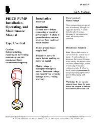
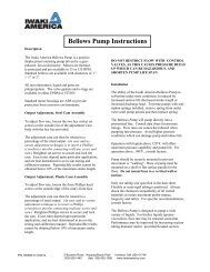
4. Place the pump in the sump; make sure that<br />
nothing interferes with switch operation.<br />
<strong>Sump</strong> Lid omitted<br />
for clarity.<br />
be grounded and should be dedicated to the<br />
sump pump.<br />
6B. The pump is supplied with a 3-wire cord set with<br />
grounding-type plug. Plug the switch directly into<br />
the outlet and plug the pump into the switch’s plug.<br />
Electrical shock hazard. Always<br />
ground the pump to a suitable electrical ground,<br />
such as a grounded water pipe, a properly<br />
grounded metallic raceway, or a ground wire<br />
system. Do not cut off the round ground pin.<br />
<strong>Sump</strong> Lid omitted<br />
for clarity.<br />
Figure 6<br />
5. Finish installing the necessary plumbing. Follow<br />
the glue manufacturer’s instructions for safety<br />
precautions and curing time.<br />
Risk of flooding. Make sure the pump<br />
cannot move in the sump. If the pump moves when it<br />
runs, the piping or sump wall may interfere with the<br />
switch and prevent the pump from starting or stopping.<br />
<strong>Sump</strong> Lid omitted<br />
for clarity.<br />
Figure 7<br />
6A. Power Supply: This pump requires a 115V., 60 Hz.,<br />
15 amp individual branch circuit. The circuit must<br />
Figure 8<br />
7A. After you have installed the piping, check valve,<br />
and switch, the pump is ready for operation.<br />
7B. Check the pump by filling the sump with water and<br />
observing the pump’s operation through one<br />
complete cycle. For switch settings see the<br />
Electrical and Switch Specifications chart on Page 7.<br />
Failure to make this operational<br />
check may lead to improper operation, premature<br />
failure, and flooding.<br />
THE INTELLISHIELD SWITCH<br />
NOTICE: Keep the IntelliShield control box dry at<br />
all times. Do not connect it to an extension cord or<br />
let it get into the sump pit.<br />
The IntelliShield switch consists of three stainless<br />
steel rods (probes) mounted vertically on the side of<br />
the pump . These are the OFF, ON, and GROUND<br />
probes (see Figure 9).<br />
Normal Operation<br />
When the water level rises to the level of the ON<br />
probe (the short stainless rod), the pump starts. As<br />
the pump runs, the water level drops. When it drops<br />
below the tip of the OFF probe (the long stainless rod<br />
with the long plastic sleeve), the pump stops.<br />
For parts or assistance, call <strong>Flotec</strong> Customer Service at 1-800-365-6832