You also want an ePaper? Increase the reach of your titles
YUMPU automatically turns print PDFs into web optimized ePapers that Google loves.
Advanced <strong>Contact</strong> Technology<br />
<strong>MA202</strong> (<strong>de</strong>_<strong>en</strong>_<strong>fr</strong>)<br />
Montageanleitung<br />
MC Mehrpolige Stift- und<br />
Buchs<strong>en</strong>einsätze 2-polig+PE<br />
bis 109-polig+PE nach Katalog<br />
Dockingline und Son<strong>de</strong>rausführung<strong>en</strong><br />
Bei <strong>de</strong>r B<strong>en</strong>utzung von an<strong>de</strong>r<strong>en</strong> als von<br />
MC angegeb<strong>en</strong><strong>en</strong> Einzelteil<strong>en</strong> und Werkzeug<strong>en</strong>,<br />
sowie bei Abweichung <strong>de</strong>r hier beschrieb<strong>en</strong><strong>en</strong><br />
Vorgänge zur Vorbereitung und<br />
Montage, kann bei <strong>de</strong>r Selbstkonfektionierung<br />
we<strong>de</strong>r die Sicherheit, noch die Einhaltung<br />
<strong>de</strong>r technisch<strong>en</strong> Dat<strong>en</strong> gewährleistet<br />
wer<strong>de</strong>n.<br />
Zum Schutz vor einem elektrisch<strong>en</strong><br />
Schlag müss<strong>en</strong> die Bauteile bei <strong>de</strong>r Montage<br />
o<strong>de</strong>r Demontage immer allseitig von <strong>de</strong>r<br />
Stromversorgung getr<strong>en</strong>nt sein.<br />
Das Steck<strong>en</strong> und Tr<strong>en</strong>n<strong>en</strong> von Steckverbindung<strong>en</strong><br />
hat g<strong>en</strong>erell in stromlosem Zustand<br />
zu erfolg<strong>en</strong>.<br />
Technische Dat<strong>en</strong> und vorkonfektionierte<br />
Bauteile siehe MC Katalog<br />
Dockingline.<br />
6<br />
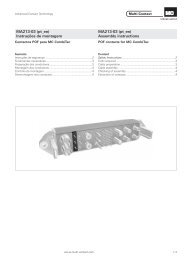
1 = Buchs<strong>en</strong>träger<br />
2 = Stiftträger<br />
3 = Verschlussstopf<strong>en</strong> MVS1/1 1)<br />
4 = Verschlussstopf<strong>en</strong> 2)<br />
5 = Buchse Ø 5-11mm<br />
6 = Buchse Ø 1-3 mm<br />
7 = Stift Ø 5-11 mm<br />
8 = Stift Ø 1-3 mm<br />
1) Der Verschlussstopf<strong>en</strong> MVS1/1pass<strong>en</strong>d<br />
für N<strong>en</strong>n-Ø 1,0mm, muss richtungsabhängig<br />
mit <strong>de</strong>r lang<strong>en</strong> Seite zur Kabelausgangsrichtung<br />
hin montiert wer<strong>de</strong>n. Er ist<br />
für <strong>de</strong>n Träger E1-18+PE (Stift und Buchs<strong>en</strong>seite)<br />
eeignet. Für E01-18PE darf kein<br />
Verschlussstopf<strong>en</strong> verw<strong>en</strong><strong>de</strong>t wer<strong>de</strong>n.<br />
Statt<strong>de</strong>ss<strong>en</strong> ist nur Vollbestückung mit<br />
Kontakt<strong>en</strong> zulässig!<br />
2) Pass<strong>en</strong>d für N<strong>en</strong>n-Ø 1,5 - 8 mm<br />
Farb<strong>en</strong>: Ø1/weiss; Ø1,2-2/blau;<br />
Ø 2,36 u. 3/gelb; Ø5/weiss;<br />
Ø6/schwarz; Ø8/schwarz<br />
5<br />
3<br />
<strong>MA202</strong> (<strong>de</strong>_<strong>en</strong>_<strong>fr</strong>)<br />
Assembly instructions<br />
MC <strong>Multi</strong>pole pin and socket<br />
inserts 2-pole+PE up to 109pole+PE<br />
according to catalogue<br />
Dockingline and special<br />
applications<br />
If, during self assembly, parts and tools<br />
other than those stated by MC are used or if<br />
the preparation and assembly instructions <strong>de</strong>scribed<br />
here are disregar<strong>de</strong>d th<strong>en</strong> neither the<br />
safety nor compliance with the technical data<br />
can be guaranteed.<br />
For protection against electrical shock,<br />
parts must be isolated <strong>fr</strong>om the power supply<br />
while being assembled or disassembled.<br />
Connectors may not be connected or<br />
disconnected un<strong>de</strong>r load.<br />
See the MC Catalogue Dockingline for<br />
technical data and assembled parts.<br />
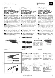
4 1 2 4<br />
ill.1<br />
1 = Socket carrier<br />
2 = Pin carrier<br />
3 = Blind plugs MVS1/1 1)<br />
4 = Blind plugs Ø 1-8 2)<br />
5 = Socket Ø 5-11 mm<br />
6 = Socket Ø 1-3 mm<br />
7 = Plug Ø 5-11 mm<br />
8 = Plug Ø 1-3 mm<br />
1) The blind plug MVS1/1, suitable for<br />
nominal Ø 1mm, must be assembled<br />
with the long si<strong>de</strong> facing the direction of<br />
the cable <strong>en</strong>try.<br />
The blind plug is only suitable for the<br />
E1-18+PE (Pin + socket si<strong>de</strong>).<br />
For the E01-18PE a blind plug may not be<br />
used. In place of this it is permitted to<br />
completely fill the part with all contacts.<br />
2) Suitable for nominal-Ø 1,5 - 8 mm<br />
Colours: Ø1/white; Ø1,2-2/blue;<br />
Ø 2,36 u. 3/yellow; Ø5/white;<br />
Ø6/black; Ø8/black<br />
www.multi-contact.com<br />
<strong>MA202</strong> (<strong>de</strong>_<strong>en</strong>_<strong>fr</strong>)<br />
Instructions <strong>de</strong> montage<br />
Inserts mâles et femelles multipolaires<br />
MC 2-pôles+T jusqu'à<br />
109-pôles+T selon catalogue<br />
Dockingline et applications<br />
spéciales<br />
Lors <strong>de</strong> l’assemblage, si <strong>de</strong>s composants<br />
et <strong>de</strong>s outils différ<strong>en</strong>ts <strong>de</strong> ceux prescrits<br />
par MC étai<strong>en</strong>t utilisés, si <strong>en</strong> outre les instructions<br />
<strong>de</strong> montage ci-après n’étai<strong>en</strong>t pas<br />
strictem<strong>en</strong>t appliquées, ni la sécurité, ni la<br />
conformité aux caractéristiques techniques<br />
ne saurai<strong>en</strong>t être garanties.<br />
En vue <strong>de</strong> garantir une protection contre<br />
les chocs électriques, il est indisp<strong>en</strong>sable<br />
<strong>de</strong> réaliser les opérations <strong>de</strong> montage et <strong>de</strong><br />
démontage hors t<strong>en</strong>sion, <strong>en</strong> veillant à déconnecter<br />
les différ<strong>en</strong>ts composants <strong>de</strong> toute alim<strong>en</strong>tation<br />
électrique.<br />
En règle générale, il ne faut pas embrocher<br />
ou débrocher un connecteur sous charge.<br />
Caractéristiques techniques et pièces<br />
constituantes: consulter le catalogue MC<br />
Dockingline.<br />
1 = Support <strong>de</strong> douilles<br />
2 = Support <strong>de</strong> broches<br />
3 = Bouchon d’obturation MVS1/1 1)<br />
4 = Bouchon d'obturation Ø 1-8 2)<br />
5 = Douille Ø 5-11 mm<br />
6 = Douille Ø 1-3 mm<br />
7 = Broche Ø 5-11 mm<br />
8 = Broche Ø 1-3 mm<br />
1) La partie longue du bouchon d’obturation<br />
MVS1/1 doit être montée dans la direction<br />
<strong>de</strong> la sortie <strong>de</strong> câble. Le bouchon<br />
d’obturation n’est approprié qu’au<br />
support E1-18+PE (Support <strong>de</strong> broche et<br />
<strong>de</strong> douille). Aucun bouchon d’obturation<br />
ne doit être utilisé dans les support E01-<br />
18PE. Ne sont admis que les supports<br />
intégralem<strong>en</strong>t montés avec <strong>de</strong>s contacts.<br />
2) Convi<strong>en</strong>t pour Ø nominal 1,5 - 8 mm<br />
Couleurs: Ø1/blanc; Ø1,2-2/bleu;<br />
Ø 2,36 u. 3/jaune; Ø5/blanc;<br />
Ø6/noir; Ø8/noir<br />
7<br />
8<br />
3<br />
1/8
Advanced <strong>Contact</strong> Technology<br />
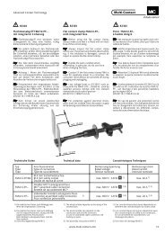
ill.2<br />
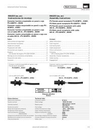
1) Crimpzange nur bis 35mm² zulässig<br />
2) Einsätze zweiseitig verw<strong>en</strong>dbar. Ziffern<br />
9 & 13 bzw. 11 & 14,5 = Crimphüls<strong>en</strong><br />
Auss<strong>en</strong>-Ø<br />
3) Für Pilotkontakte. Nicht für UL-Steckverbin<strong>de</strong>r.<br />
4) Diese Werkzeuge und Einsätze müss<strong>en</strong><br />
für UL-Anw<strong>en</strong>dung<strong>en</strong> verw<strong>en</strong><strong>de</strong>t wer<strong>de</strong>n.<br />
2/8<br />
a<br />
Notw<strong>en</strong>diges Werkzeug / Tools required / Outillage nécessaire<br />
bc<strong>de</strong>f<br />
siehe MA224-<strong>de</strong>f siehe MA226-<strong>de</strong>f<br />
l m n<br />
Typ Bestell Nr. Leiterquerschnitt Bezeichnung<br />
Pos. Type Or<strong>de</strong>r No. Conductor cross-section L±0,5<br />
Description<br />
Type No. <strong>de</strong> C<strong>de</strong> Section du conducteur (ill.6) Désignation<br />
mm² AWG mm<br />
a M-PZ131)4) 18.3700 - - Crimpzange / Crimping pliers / Pince à sertir<br />
b MES-PZ-TB 5/6 18.3701 6 10 Einsatz für a / Insert for a / Matrice pour a<br />
c MES-PZ-TB 8/10 18.3702 10 12 Einsatz für a / Insert for a / Matrice pour a<br />
d MES-PZ-TB 9/164) 18.3703 16 6 12 Einsatz für a / Insert for a / Matrice pour a<br />
e MES-PZ-TB 11/25 18.3704 25 4 14 Einsatz für a / Insert for a / Matrice pour a<br />
f MES-PZ-TB 13/35 18.3705 35 2;(1) 15 Einsatz für a / Insert for a / Matrice pour a<br />
g M-PZ-T2600 18.3710 - - - Crimpzange / Crimping pliers / Pince à sertir<br />
h TB8-17 18.3711 10 & 70 7&00 12/25 Einsatz für g / Insert for g / Matrice pour g<br />
i TB9-132) 18.3712 16 & 35 6&2(1) 12/15 Einsatz für g / Insert for g / Matrice pour g<br />
j TB11-14,52) 18.3713 25 & 50 4&1 14/22 Einsatz für g / Insert for g / Matrice pour g<br />
k M-CZ3) 18.3800 - - Crimpzange / Crimping pliers / Pince à sertir<br />
l MES-CZ 18.3801 - - - Locator für k / Locator for k / Locateur pour k<br />
m MES-CZ1,5/2 18.3802 0,5-1,5 - 7 Einsatz für k / Insert for k / Matrice pour k<br />
n MES-CZ1/1.57 18.3803 0,25-1,5 - 5 Einsatz für k / Insert for k / Matrice pour k<br />
MBT 17-70-50 18.3026 70 00 25 Ergänz<strong>en</strong><strong>de</strong> Einsätze für M-KO-RL<br />
MBT 20-95-50 18.3027 95 000 27 Optional additional inserts for M-KO-RL<br />
Matrices complém<strong>en</strong>taires pour M-KO-RL<br />
Werkzeugkoffer Roboticline komplett<br />
Tool case Roboticline complete<br />
Cof<strong>fr</strong>e d’outils Roboticline complet<br />
Inhalt / Cont<strong>en</strong>t / Cont<strong>en</strong>u:<br />
M-KO-RL4) 18.3100 Elektro-hydraulische-crimpzange<br />
/ Cordless electro hydraulic crimping tool /<br />
Outil electro-hydraulique <strong>de</strong> sertissage<br />
Einsätze / Inserts / Matrices Leiterquerschnitt/Conductor cross-section/Section du conducteur L±0,5 (ill.6)<br />
MBT 11-25-504) 18.3023 25mm² / 4 AWG 14<br />
MBT 13-35-504) 18.3024 35mm² / 2 (1) AWG 15<br />
MBT 14,5-50-504) 18.3025 50mm² / 1 AWG 22<br />
ME-WZ11/38 18.3021 Einsetzwerkzeug Stift/Buchse - Insertion tool pin/socket - Outil <strong>de</strong> montage broche/douille<br />
MSA-WZ8 18.3022 Stiftausbauwerkzeug - Extraction tool (pin) - Outil <strong>de</strong> démontage (broche)<br />
MBA-WZ6<br />
2 Akkus / 2 Batteries<br />
18.3017 Buchs<strong>en</strong>ausbauwerkzeug - Extraction tool (socket) - Outil <strong>de</strong> démontage (douille)<br />
La<strong>de</strong>gerät / Battery charger / Chargeur<br />
1) Crimping pliers up to 35mm² max.<br />
2) Each insert can be used on two si<strong>de</strong>s.<br />
Numerals 9 & 13 or 11 & 14,5 = outer-<br />
Ø of crimping sleeves<br />
3) For pilot contacts. Not for UL connectors.<br />
4) These crimping pliers and inserts shall be<br />
used for UL applications.<br />
www.multi-contact.com<br />
g<br />
h<br />
i<br />
j<br />
k<br />
1) Pince à sertir pour max. 35mm².<br />
2) Les matrices peuv<strong>en</strong>t être utilisées <strong>de</strong>s<br />
<strong>de</strong>ux côtés. Les nombres 9 & 13 ou<br />
11 & 14,5 = Ø-extérieur du fût à sertir.<br />
3) Pour contacts pilotes. Pas pour les<br />
connecteurs UL.<br />
4) Ces pinces à sertir et matrices doiv<strong>en</strong>t<br />
être utilisées pour toute application UL.
Advanced <strong>Contact</strong> Technology<br />
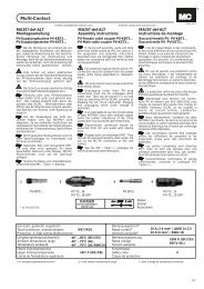
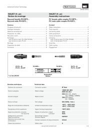
ill.3<br />
ill.3<br />
Einsetzwerkzeug Stift/Buchse Bestell-Nr. Für N<strong>en</strong>n-Ø Stift/Buchse<br />
Insertion tool pin/socket Or<strong>de</strong>r No. For Nom.-Ø pin/socket<br />
Outil <strong>de</strong> montage broche/douille No. <strong>de</strong> C<strong>de</strong> Pour Ø-nom. broche/douille<br />
ME-WZ-1/1,2 18.3000 1/1,2<br />
ME-WZ-1,5/2 18.3003 1,5/1,57/2/2,36<br />
ME-WZ-3 18.3010 3<br />
ME-WZ-5 18.3013 5<br />
ME-WZ-6 18.3016 6<br />
ME-WZ-11/38 18.3021 8/11<br />
ill.4<br />
Stiftausbauwerkzeug Bestell-Nr. Für N<strong>en</strong>n-Ø Stift/Buchse (mm)<br />
Extraction tool (pin) Or<strong>de</strong>r No. For Nom.-Ø pin/socket (mm)<br />
Outil <strong>de</strong> démontage (broche) No. <strong>de</strong> C<strong>de</strong> Pour Ø-nom. broche/douille (mm)<br />
MSA-WZ-1/1,2 18.3002 1 / 1,2<br />
MSA-WZ-1,5 18.3005 1,5 / 1,57<br />
MSA-WZ-1,5/109 18.3020 1) 1,5<br />
MSA-WZ-2 18.3009 2<br />
MSA-WZ-3 18.3012 2,36 / 3<br />
MSA-WZ-5 18.3015 5<br />
MSA-WZ-6 18.3018 6<br />
MSA-WZ-8 18.3022 8<br />
MBA-WZ-5 18.3014 11<br />
ill.5<br />
Buchs<strong>en</strong>ausbauwerkzeug Bestell-Nr. Für N<strong>en</strong>n-Ø Stift/Buchse (mm)<br />
Extraction tool (socket) Or<strong>de</strong>r No. For Nom.-Ø pin/socket (mm)<br />
Outil <strong>de</strong> démontage (douille) No. <strong>de</strong> C<strong>de</strong> Pour Ø-nom. broche/douille (mm)<br />
MBA-WZ-1/1,2 18.3001 1 / 1,2<br />
MBA-WZ-1,5 18.3004 1,5 / 1,57<br />
MBA-WZ-1,5/109 18.3019 1) 1,5<br />
MBA-WZ-2 18.3008 2 / 2,36<br />
MBA-WZ-3 18.3011 3<br />
MBA-WZ-5 18.3014 5<br />
MBA-WZ-6 18.3017 6 / 8<br />
MSA-WZ-8 18.3022 11<br />
1) Für 58-polige bzw. 109-polige<br />
Ausführung<br />
ill.4 ill.5<br />
1) For 58-pole or 109-pole connectors 1) Pour les connecteurs 58-pôles ou<br />
109-pôles<br />
www.multi-contact.com<br />
3/8
Advanced <strong>Contact</strong> Technology<br />
Vorbereit<strong>en</strong> <strong>de</strong>r Leitung Cable preparation Préparation du câble<br />
(ill.6)<br />
Leitung auf Mass Lx abisolier<strong>en</strong>. Lx<br />
<strong>en</strong>tsprech<strong>en</strong>d Gehäusegrösse und<br />
Leitungsart ermitteln. Richtwerte für<br />
MC Standardgehäuse:<br />
Gehäusegrösse Lx (mm)<br />
1 40<br />
2 40<br />
3 55<br />
4 70<br />
Lx<br />
L<br />
(ill.6)<br />
Strip cable insulation to dim<strong>en</strong>sion Lx.<br />
Lx <strong>de</strong>p<strong>en</strong>ds on housing size and type of<br />
cable . Approximate figures for<br />
standard MC housings:<br />
ill.6 ill.6 ill.6<br />
Einzelleiter auf Mass L abisolier<strong>en</strong><br />
gem. Tab.1<br />
Tab. 1<br />
N<strong>en</strong>n-Ø Stift/Buchse<br />
Nom-Ø pin/socket<br />
Ø-nom. broche/douille<br />
Leiterquerschnitt<br />
Conductor cross-section<br />
Section du câble<br />
Housing size Lx (mm)<br />
1 40<br />
2 40<br />
3 55<br />
4 70<br />
Strip wire insulation to dim<strong>en</strong>sion L<br />
according to Tab. 1<br />
L ±0,5<br />
Crimpzange M-CZ<br />
Crimping pliers M-CZ<br />
Pince à sertir M-CZ<br />
Lx<br />
Selector AWG No.<br />
Selektor AWG/Nr.<br />
Selecteur AWG No.<br />
L<br />
Einsatz zu M-PZ-13<br />
Insert for M-PZ-13<br />
Matrice pour M-PZ-13<br />
(ill.6)<br />
Dénu<strong>de</strong>r le câble sur la longueur Lx.<br />
Lx dép<strong>en</strong>d <strong>de</strong> la taille du boîtier et du<br />
type <strong>de</strong> câble. Valeurs approximatives<br />
pour les boîtiers standards MC<br />
Taille du boîtier Lx (mm)<br />
1 40<br />
2 40<br />
3 55<br />
4 70<br />
Dénu<strong>de</strong>r les conducteurs sur la<br />
longueur L selon Tab. 1<br />
Einsatz zu M-PZ-T2600<br />
Insert for M-PZ-T2600<br />
Matrice pour M-PZ-T2600<br />
Lx<br />
Einsatz zu Cembre B51<br />
Insert for Cembre B51<br />
Matrice pour Cembre B51<br />
mm<br />
2<br />
mm AWG mm AWG Nr./No./No.<br />
1/1,5 0,14/0,2/0,34/0,5 26/24/22/20 5 26/24/22/20 2/3/4<br />
1,2 0,25-0,75 22/20 5 22/20 3/4<br />
1,57 0,5 20 5 20 4<br />
1/1,5/2 0,5 20/18 7 20/18 4/5<br />
1/1,5/2 0,75 7 18 5<br />
1/1,5/2 1 18 7 18 5<br />
1,5/2 1,5 16 7 16 6<br />
2 1,5/2,5 16/14 7 14/12 7/8<br />
2,36 0,5-1,5 20/16 7 20/18/16 4/5/6<br />
3 2,5 12 7 12 8<br />
3 4 7 12 8<br />
5/6 6 11 MES-PZ-TB6/5<br />
5/6 10 13 MES-PZ-TB8/10<br />
6 16 13 MES-PZ-TB9/16 TB9-13<br />
6/8 25 15 MES-PZ-TB11/25 TB11-14,5 MBT11-25-50<br />
8/11 35 15 MES-PZ-TB13/35 TB9-13 MBT13-35-50<br />
11 38 18 MES-PZ-TB13/35<br />
11 50 22 TB11-14,5 MBT14,5-50-50<br />
4/8<br />
www.multi-contact.com<br />
L
Advanced <strong>Contact</strong> Technology<br />
Achtung:<br />
Für Anschlüsse <strong>de</strong>r Stift- und Buchs<strong>en</strong>einsätze<br />
ME3-36+PE...2/2,5 gilt das<br />
Mass L = 7±0,5 eb<strong>en</strong>so gelt<strong>en</strong> die folg<strong>en</strong><strong>de</strong>n<br />
Selectoreinstellung<strong>en</strong> für die<br />
Crimpzange (MES-CZ). Zu<strong>de</strong>m sind für<br />
Leiterquerschnitte von<br />
0,14 mm2 bis 1 mm2 Reduzierhüls<strong>en</strong><br />
als zusätzliche Einlag<strong>en</strong> in <strong>de</strong>n Crimphüls<strong>en</strong><br />
erfor<strong>de</strong>rlich. Geeignet sind A<strong>de</strong>r<strong>en</strong>dhüls<strong>en</strong><br />
nach DIN 46228 / N<strong>en</strong>nquerschnitt<br />
1,0/6 lang, Oberfläche versilbert.<br />
(z.B. von Fa. Klauke Typ 72S/6).<br />
Att<strong>en</strong>tion:<br />
For the connections of pin and socket inserts<br />
ME3-36+PE...2/25 the size L is<br />
7±0,5. For the selector position of the<br />
crimping tool (MES-CZ) the<br />
following settings have to be used and<br />
wh<strong>en</strong> working with cross-sections of<br />
0,14 mm2 to 1 mm2 it is necessary to<br />
use a reducing sleeve in the crimp<br />
barrel. Wire <strong>en</strong>d ferrules accord. to DIN<br />
46228 nom. cross-section 1,0/6 long<br />
and silver plated are suitable for this purpose.<br />
(e.g. Klauke type 72S/6).<br />
Leiterquerschnitt Selector Position<br />
Conductor cross- section Selector position<br />
Section du conducteur Position du selecteur<br />
0,14 mm2 18/5<br />
0,25 mm2<br />
18/5<br />
0,5 mm2<br />
16/6<br />
0,75 mm2<br />
16/6<br />
1,0 mm2<br />
14/7<br />
1,5 mm2<br />
14/7<br />
2,5 mm2<br />
12/8<br />
Att<strong>en</strong>tion:<br />
Pour le raccor<strong>de</strong>m<strong>en</strong>t <strong>de</strong>s supports <strong>de</strong><br />
broches et <strong>de</strong> douilles ME3-<br />
36+PE...2/2,5 respecter la cote L =<br />
7±0,5. Pour le réglage du sélecteur<br />
(MES-CZ) <strong>de</strong> la pince à sertir respecter<br />
les positions précisées ci-<strong>de</strong>sous .<br />
Pour les sections <strong>de</strong> câbles <strong>de</strong><br />
0,14 mm2à1mm 2,<br />
il convi<strong>en</strong>dra impérativem<strong>en</strong>t<br />
d’utiliser <strong>de</strong>s fûts <strong>de</strong> réduction<br />
(à monter dans les fûts à sertir). A<br />
cet effet, <strong>de</strong>s embouts <strong>de</strong> câble selon<br />
DIN 46228 / section nominale 1,0 / Longueur<br />
6, arg<strong>en</strong>tés, peuv<strong>en</strong>t être utilisés.<br />
(Exemple: type 72S/6 <strong>de</strong> la société<br />
Klauke).<br />
Crimp<strong>en</strong> <strong>de</strong>r Kontakte Crimping the contacts Sertissage <strong>de</strong>s contacts<br />
(ill.7)<br />
Achtung:<br />
Im Bedarfsfall Kabelverschraubung<br />
und Gehäuserückteil,<br />
vor Ancrimp<strong>en</strong> auf<br />
Leitung auffä<strong>de</strong>ln.<br />
ill.7<br />
(ill.7)<br />
Att<strong>en</strong>tion:<br />
Slip the cable gland and back<br />
section of housing on the cable<br />
before crimping.<br />
www.multi-contact.com<br />
(ill.7)<br />
Att<strong>en</strong>tion:<br />
Avant <strong>de</strong> sertir, <strong>en</strong>filer le<br />
presse-étoupe et le boîtier<br />
arrière sur le câble.<br />
5/8
Advanced <strong>Contact</strong> Technology<br />
(ill.8)<br />
Beim Einleg<strong>en</strong> <strong>de</strong>r Crimphülse<br />
Crimpzone (C) beacht<strong>en</strong>.<br />
Einzelleiter in die Crimphülse <strong>de</strong>s<br />
Kontaktes bis zum Anschlag<br />
einführ<strong>en</strong>. Einzelleiter müss<strong>en</strong> im<br />
Sichtloch sichtbar sein.<br />
(ill.9)<br />
Crimpvorgang ausführ<strong>en</strong>. Leiter dabei<br />
leicht in axialer Richtung in<br />
Crimphülse drück<strong>en</strong>.<br />
6/8<br />
C 2mm<br />
Sichtloch<br />
Control hole<br />
Orifice <strong>de</strong> contrôle<br />
ill.8<br />
(ill.8)<br />
Wh<strong>en</strong> inserting the crimping sleeve in<br />
the tool, use crimp zone (C).<br />
Fully insert lead into the crimping<br />
sleeve. Leads must be visible in the<br />
contole hole.<br />
ill.9<br />
(ill.9)<br />
Crimp the wire, pushing it g<strong>en</strong>tly into<br />
the sleeve while doing so.<br />
www.multi-contact.com<br />
(ill.8)<br />
Veiller à bi<strong>en</strong> respecter la zone <strong>de</strong><br />
sertissage (C).<br />
Introduire le câble dans le fût à sertir<br />
jusqu'<strong>en</strong> butée. Le câble doit être<br />
visible dans l’orifice <strong>de</strong> contrôle.<br />
(ill.9)<br />
Sertir tout <strong>en</strong> maint<strong>en</strong>ant le conducteur<br />
<strong>en</strong> position dans le fût (pousser<br />
axialem<strong>en</strong>t).
Advanced <strong>Contact</strong> Technology<br />
Sichtloch<br />
Control hole<br />
Orifice <strong>de</strong> contrôle<br />
Sichtloch<br />
Control hole<br />
Orifice <strong>de</strong> contrôle<br />
ill.10<br />
(ill.10)<br />
Angeschloss<strong>en</strong>e Leiter müss<strong>en</strong> vor<br />
und nach <strong>de</strong>m Crimp<strong>en</strong> im Sichtloch<br />
sichtbar sein. Leiter darf sich nicht aus<br />
<strong>de</strong>r Crimphülse herauszieh<strong>en</strong> o<strong>de</strong>r<br />
abreiss<strong>en</strong> lass<strong>en</strong>. (Kontrolle !).<br />
Hinweis:<br />
Beim Ancrimp<strong>en</strong> von Thermopaar-<br />
Druckkontakt<strong>en</strong> bitte folg<strong>en</strong><strong>de</strong>s<br />
beacht<strong>en</strong>:<br />
1- Kontakte an die <strong>en</strong>tsprech<strong>en</strong><strong>de</strong>n<br />
Kabel anschliess<strong>en</strong>:<br />
- Chromel Kontakte an Chromel<br />
Leiter<br />
- Alumel Kontakte an Alumel<br />
Leiter<br />
2- Bei Anschluss <strong>de</strong>s Buchs<strong>en</strong>kontaktes<br />
eine kleine Kabelschleife<br />
lass<strong>en</strong>.<br />
Einbau <strong>de</strong>r Kontakte Installation of the contacts Assemblage du connecteur<br />
Hinweis:<br />
Der Einpressvorgang kann erleichtert<br />
wer<strong>de</strong>n, w<strong>en</strong>n die Stift- bzw.<br />
Buchs<strong>en</strong>träger vor <strong>de</strong>m Einsetz<strong>en</strong> <strong>de</strong>r<br />
Kontakte in Spiritus o<strong>de</strong>r Industriealkohol<br />
getaucht wer<strong>de</strong>n. Keine<br />
fetthaltig<strong>en</strong> Medi<strong>en</strong> (kein Talkum)<br />
b<strong>en</strong>utz<strong>en</strong>. Nichtbelegte Kontaktkammern<br />
müss<strong>en</strong> mit Verschlussstopf<strong>en</strong><br />
verseh<strong>en</strong> wer<strong>de</strong>n.<br />
(ill.11)<br />
Kontakte in die Kontaktkammern <strong>de</strong>r<br />
Stift- bzw. Buchs<strong>en</strong>träger von <strong>de</strong>r<br />
Anschlußseite her (grösserer Ø <strong>de</strong>r<br />
Kontaktkammern) mit normaler<br />
Handkraft vorsteck<strong>en</strong>.<br />
Kontakte mit Kontakteinsatz-werkzeug<br />
(siehe S. 3/8) eindrück<strong>en</strong>.<br />
Beim Stifteinbau wird als Montagehilfe<br />
ein Stiftgehäusevor<strong>de</strong>rteil<br />
empfohl<strong>en</strong>. Beim Buchs<strong>en</strong>einbau wird<br />
<strong>de</strong>r Buchs<strong>en</strong>träger auf eine eb<strong>en</strong>e<br />
(ill.10)<br />
Wire must be visible in the control<br />
hole before and after crimping. Check<br />
that the<br />
wire can not be pulled or turned out of<br />
the crimping sleeve (Control !)<br />
Note:<br />
Wh<strong>en</strong> crimping on thermocouple<br />
pressure contacts, please observe the<br />
following:<br />
1- Fit contacts on the appropriate<br />
cables:<br />
- Chromel contacts on chromel<br />
conductors<br />
- Alumel contacts on alumel<br />
conductors<br />
2- Wh<strong>en</strong> attaching the socket<br />
contact, leave a small loop of cable.<br />
Installation tips:<br />
To facilitate installation, immerse the<br />
pin or socket carrier in spirits or<br />
industrial alcohol before inserting the<br />
contacts. Do not use any greasy media<br />
(no talc).<br />
Plug any unoccupied contact holes with<br />
(ill.11)<br />
Insert contacts by hand into the contact<br />
holes of the pin or socket carrier <strong>fr</strong>om<br />
the connection si<strong>de</strong> (larger hole<br />
diameter).<br />
Press in the contacts with the<br />
insertion tool (see page 3/8).<br />
For pin installation, it is advisable to use<br />
a <strong>fr</strong>ont section of the right size housing<br />
as assembly jig. For socket installation,<br />
simply place socket carrier directly onto<br />
a flat b<strong>en</strong>ch.<br />
www.multi-contact.com<br />
ill.11<br />
(ill.10)<br />
Le conducteur doit être visible dans<br />
l'orifice <strong>de</strong> contrôle avant et après<br />
sertissage. Vérifier la qualité <strong>de</strong><br />
sertissage <strong>en</strong> exerçant une traction<br />
sur le conducteur.<br />
Remarques:<br />
Lors <strong>de</strong> sertissage <strong>de</strong>s contacts à<br />
thermocouple, veiller à:<br />
1- Sertir les câbles avec les contacts<br />
correspondants:<br />
- <strong>Contact</strong> Chromel avec le<br />
conducteur Chromel<br />
- <strong>Contact</strong> Alumel avec le<br />
conducteur Alumel<br />
2- Côté raccor<strong>de</strong>m<strong>en</strong>t <strong>de</strong> la douille,<br />
former une boucle avec le conducteur.<br />
Remarques:<br />
Le montage <strong>de</strong>s broches et <strong>de</strong>s<br />
douilles peut être facilité <strong>en</strong> plongeant<br />
les supports dans du "White spirit" ou<br />
un alcool industriel, mais ne pas utiliser<br />
<strong>de</strong>s substances grasses (pas <strong>de</strong> talc).<br />
Mettre <strong>de</strong>s bouchons d'obturation<br />
dans les logem<strong>en</strong>ts non utilisés.<br />
(ill.11)<br />
Emmancher à la main les contacts<br />
dans leur logem<strong>en</strong>t respectif, par la<br />
face arrière du corps isolant (grand<br />
diamètre <strong>de</strong>s logem<strong>en</strong>ts). Terminer le<br />
montage <strong>de</strong>s contacts à l'ai<strong>de</strong> <strong>de</strong> l'outil<br />
approprié (voir page 3/8).<br />
Pour le montage <strong>de</strong>s broches, poser le<br />
support isolant sur le boîtier avant<br />
correspondant. Pour le montage <strong>de</strong>s<br />
douilles, poser le support isolant sur<br />
7/8
Advanced <strong>Contact</strong> Technology<br />
(ill.13 + 14)<br />
ME1.../ME2...<br />
Beim Stifteinsatz ME1... und ME2...<br />
sind alle PE-Stiftkontake zur Standardkontakteb<strong>en</strong>e<br />
voreil<strong>en</strong>d.<br />
ME3.../ME4...<br />
Beim Stifteinsatz ME3.../ME4... sind<br />
nur die PE-Stiftkontakte bis Kontakt-Ø<br />
2 mm voreil<strong>en</strong>d. Stiftkontakte ab Ø 3<br />
mm müss<strong>en</strong> steckseitig gleich weit<br />
aus <strong>de</strong>m Stiftträger steh<strong>en</strong>, kein voreil<strong>en</strong><strong>de</strong>r<br />
Stiftkontakt. Bei Buchs<strong>en</strong> ab<br />
Ø 3 mm eilt die PE-Buchse im<br />
Buchs<strong>en</strong>träger vor. Kontaktträger (z.B.<br />
Hybridträger) mit Schirmkontakt (S) ist<br />
<strong>de</strong>r Schirmkontakt zu <strong>de</strong>n Steuerkontakt<strong>en</strong><br />
voreil<strong>en</strong>d, zum PE jedoch<br />
nacheil<strong>en</strong>d.<br />
Die Details hierzu fin<strong>de</strong>n Sie auf <strong>de</strong>n<br />
(ill.15)<br />
Zu weit eingedrückte Buchs<strong>en</strong><br />
wer<strong>de</strong>n mit <strong>de</strong>m Buchs<strong>en</strong>ausbauwerkzeug<br />
(S.3/8) bis zu ihrer Einrastlage<br />
zurückgedrückt.<br />
Bei Belegungsfehlern und<br />
Reparatur<strong>en</strong> wer<strong>de</strong>n die Kontakte mit<br />
<strong>de</strong>n <strong>en</strong>tsprech<strong>en</strong><strong>de</strong>n Ausbauwerkzeug<strong>en</strong><br />
(siehe S.3/8) aus <strong>de</strong>n<br />
Kontaktträgern gedrückt und neu<br />
eingesetzt.<br />
8/8<br />
Industriealkohol<br />
Industrial alcohol<br />
(ill.12)<br />
Werkzeug beim Eindrück<strong>en</strong> und<br />
Herauszieh<strong>en</strong> parallel zur Achse<br />
Überprüfung auf einwand<strong>fr</strong>eie<br />
Konfektionierung<br />
Control of correct assembly<br />
ill.13 ill.14<br />
<strong>MA202</strong> (<strong>de</strong>_<strong>en</strong>_<strong>fr</strong>)<br />
ill.12<br />
(ill.12)<br />
Be sure to keep tool straight wh<strong>en</strong><br />
installing or removing contacts.<br />
(ill.13 + 14)<br />
ME1.../ME2...<br />
all types of PE pins are in advanced<br />
position (mating first, braking last)<br />
compared to the other contacts.<br />
ME3.../ME4...<br />
In male inserts ME3... and ME4...only<br />
PE pin contacts up to Ø 2 mm are in<br />
advanced position. PE contacts of<br />
Ø 3 mm and above are on the same<br />
level as the other pins (no leading<br />
contact). Regarding female inserts, for<br />
sockets of Ø 3 mm or larger, the PE<br />
socket is in advanced positon.<br />
In contact carriers (e.g. hybrid carriers)<br />
with a shield contact (S) the shield<br />
contact is in advanced position<br />
compared to the control contacts, but<br />
lagging behind the PE contact.<br />
You will find the relevant <strong>de</strong>tails on<br />
the product drawings.<br />
(ill.15)<br />
Sockets pressed in too far can be<br />
turned back to their proper seating<br />
position with the socket extraction tool<br />
(p.3/8).<br />
By repairs or installation errors, remove<br />
the contacts <strong>fr</strong>om the contact<br />
carrier with the respective extraction<br />
tool (see page 3/8) and th<strong>en</strong> reinstall<br />
(ill.12)<br />
Lors du montage ou du démontage<br />
<strong>de</strong>s contacts, veiller à manipuler les<br />
Contrôle du montage<br />
(ill.13 + 14)<br />
ME1.../ME2...<br />
Sur les inserts mâles ME1... et<br />
ME2..., tous les contacts <strong>de</strong> terre<br />
(PE) sont <strong>en</strong> position avancée par<br />
rapport aux autres broches.<br />
ME3.../ME4...<br />
Sur les inserts mâles ME3... et<br />
ME4..., seuls les contacts <strong>de</strong> terre<br />
jusqu'au Ø 2 mm sont avancés. Les<br />
contacts mâles à partir du Ø 3 mm<br />
doiv<strong>en</strong>t être au même niveau que les<br />
autres (pas <strong>de</strong> broche avancée).<br />
Pour les douilles à partir du Ø 3 mm,<br />
la douille <strong>de</strong> terre PE est <strong>en</strong> position<br />
avancée dans l’isolant. Sur les<br />
supports isolants (p. ex. support<br />
hybri<strong>de</strong>) avec contact <strong>de</strong> blindage (S),<br />
la douille <strong>de</strong> blindage est avancée par<br />
rapport aux autres contacts, mais <strong>en</strong><br />
arrière par rapport à la douille <strong>de</strong><br />
terre. Vous trouverez les détails à ce<br />
sujet sur les plans <strong>de</strong>s produits.<br />
ill.15<br />
(ill.15)<br />
Les douilles montées trop <strong>en</strong> avant<br />
peuv<strong>en</strong>t être ram<strong>en</strong>ées dans leur<br />
position nominale à l'ai<strong>de</strong> <strong>de</strong> l'outil <strong>de</strong><br />
démontage (pour douille), (p.3/8).<br />
Lors d'une réparation, les contacts<br />
seront extraits du support isolant avec<br />
l'outil <strong>de</strong> démontage approprié (voir<br />
page 3/8).<br />
Än<strong>de</strong>rung<strong>en</strong> vorbehalt<strong>en</strong>/Subject to alterations/Modifications sous réserve<br />
Copyright by <strong>Multi</strong>-<strong>Contact</strong> AG, Switzerland / Docking line / 08.2011 / In<strong>de</strong>x l<br />
www.multi-contact.com