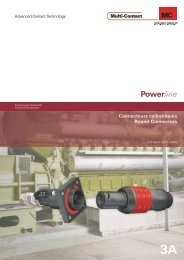
Multi-Contact
Multi-Contact
Multi-Contact

Create successful ePaper yourself
Turn your PDF publications into a flip-book with our unique Google optimized e-Paper software.
<strong>Multi</strong>-<strong>Contact</strong><br />
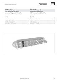
MA207-def-ALT<br />
Montageanleitung<br />
PV-Kupplungsbuchse PV-KBT3...<br />
PV-Kupplungsstecker PV-KST3...<br />
Bei der Benützung von anderen als von<br />
MC angegebenen Einzelteilen und Werkzeugen,<br />
sowie bei Abweichung der hier beschriebenen<br />
Vorgänge zur Vorbereitung und<br />
Montage, kann bei der Selbstkonfektionierung<br />
weder die Sicherheit, noch die Einhaltung der<br />
technischen Daten gewährleistet werden.<br />
Zum Schutz vor einem elektrischen<br />
Schlag müssen bei der Selbstkonfektionierung<br />
der PV-Steckverbinder diese immer allseitig<br />
von der Stromversorgung getrennt sein.<br />
Der Schutz vor einem elektrischen Schlag<br />
muss durch das Endprodukt gegeben sein.<br />
Trennung unter Last: PV-Steckverbindungen<br />
dürfen nicht unter Last getrennt werden.<br />
Der lastlose Zustand kann durch Abschalten<br />
des DC/AC - Wechselrichters oder<br />
Öffnen des AC-Stromkreises erreicht werden.<br />
Das Stecken und Trennen unter Spannung ist<br />
möglich.<br />
Von der Verwendung von nicht verzinnten<br />
Kabeln vom Typ H07RN-F wird<br />
abgeraten, da bei oxidierten Kupferlitzen die<br />
zugelassenen Grenzwerte der Uebergangswiderstände<br />
der Crimpverbindung überschritten<br />
werden können.<br />
Nicht gesteckte Steckverbinder sind mit<br />
einer Verschlusskappe vor Feuchtigkeit und<br />
Schmutz zu schützen.<br />
Gesteckte Teile sind wasserdicht IP67.<br />
Sie sind aber nicht geeignet für einen<br />
dauerhaften Gebrauch unter Wasser. MC-PV-<br />
Steckverbinder nicht auf die Dachhaut<br />
auflegen.<br />
Technische Daten und vorkonfektionierte<br />
Bauteile siehe MC 1 Solarline<br />
Katalog .<br />
1<br />
* UL file E181720<br />
E-Mail: basel@multi-contact.com<br />
PV-BP3/... PV-T3.../B<br />
PV-T3.../B-UR*<br />
MA207-def-ALT<br />
Assembly instructions<br />
PV-Female cable coupler PV-KBT3...<br />
PV-Male cable coupler PV-KST3...<br />
If, during self assembly, parts and tools<br />
other than those stated by MC are used or if<br />
the preparation and assembly instructions<br />
described here are disregarded then neither<br />
safety nor compliance with the technical data<br />
can be guaranteed<br />
For protection against electric shock, PVconnectors<br />
must be isolated from the power<br />
supply while being assembled or disassembled.<br />
The end product must provide protection<br />
from electric shock.<br />
Unplugging under load: PV plug<br />
connections must not be unplugged while<br />
under load. They can be placed in a no load<br />
state by switching off the DC/AC converter or<br />
breaking the AC circuit interrupter. Plugging<br />
and unplugging while under voltage is<br />
permitted.<br />
It is unadvisable to use non-tinned cables<br />
of type H07RN-F, since with oxidised copper<br />
wires the contact resistances of the crimp<br />
connection may exceed the permitted limits.<br />
Disconnected connectors should be<br />
protected from dirt and water with sealing<br />
caps.<br />
Plugged parts are watertight IP67. They<br />
can not be used permanently under water. Do<br />
not lay the MC-PV connectors on the roof<br />
surface.<br />
See the MC 1 Solarline<br />
catalogue for<br />
technical data and assembled parts.<br />
Internet: www.multi-contact.com<br />
2 3 4<br />
Schutzart, gesteckt/ ungesteckt<br />
1)<br />
Bemessungsstrom<br />
Touch protection, mated/unmated IP67/IP2X<br />
1)<br />
Rated current<br />
Protection, à l’état connecté/déconnecté<br />
1)<br />
Intensité assignée<br />
Umgebungstemperaturbereich -40° ...90°C (IEC/CEI) Bemessungspannung<br />
Ambient temperature range -40° ...75°C (UL)<br />
Rated voltage<br />
Température ambiante -40° ...70°C (UL/AWG14) Tension assignée<br />
Obere Grenzstemperatur Schutzklasse<br />
Upper limiting temperature Safety class<br />
Limite de Température supérieure Classe de protection<br />
MA207-def-ALT<br />
Instructions de montage<br />
Raccord femelle PV PV-KBT3...<br />
Raccord mâle PV PV-KST3...<br />
PV-SP3/... PV-T3.../S<br />
PV-T3.../S-UR*<br />
Kleber<br />
Sticker<br />
Autocollant<br />
105° C (IEC/CEI) II<br />
1) im Umgebungstemperaturbereich 1) in the ambient temperature range 1) dans la plage de température ambiante<br />
STÄUBLI GROUP<br />
Lors de l’assemblage, si des composants<br />
et des outils différents de ceux prescrits par MC<br />
étaient utilisés, si en outre les instructions de<br />
montage ci après n’étaient pas strictement<br />
appliquées, ni la sécurité, ni la conformité aux<br />
caractéristiques techniques ne sauraient être<br />
garanties.<br />
En vue de garantir une protection contre<br />
les chocs électriques, il est indispensable de<br />
réaliser les opérations de montage et de<br />
démontage hors tension, en veillant à déconnecter<br />
les différents composants de toute alimentation<br />
électrique.<br />
La protection contre les chocs électriques<br />
doit être garantie par le produit fini (monté).<br />
Débrochage sous tension: Les connecteurs<br />
PV ne doivent pas être débrochés sous<br />
charge. Ils peuvent être placés hors charge en<br />
arrêtant l’onduleur DC/AC ou en coupant la<br />
source de courant continu. L’embrochage/débrochage<br />
sous tension reste possible.<br />
Nous déconseillons l'utilisation de câble<br />
H07RN-F non étamé, car dans le cas de brins de<br />
cuivre oxydés, la valeur maximale autorisée de la<br />
résistance électrique de la liaison par sertissage<br />
risquerait d'être dépassée.<br />
Les connecteurs doivent être protégés<br />
contre les infiltrations de poussière et les<br />
projections d’eau avec des bouchons de<br />
protection.<br />
Les parties connectées sont étanches<br />
IP67, mais ne sont pas prévues pour une<br />
utilisation permanente sous l’eau. Les connecteurs<br />
PV ne doivent pas reposer sur le toit.<br />
Caractéristiques techniques et pièces<br />
constituantes: consulter le catalogue MC<br />
1 Solarline.<br />
20 A (2-4 mm² / AWG 14-12)<br />
30 A (6 mm² / AWG 10)<br />
1000 V (IEC/CEI)<br />
600 V (UL)<br />
1/4<br />
®
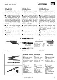
Notwendiges Werkzeug Tools required Outillage nécessaire<br />
ill.1<br />
PV-WZ3/III<br />
PV-WZ3<br />
(ill.1)<br />
Montage-Vorrichtung mit Montagegerät<br />
(C), Gegenhalter (D) und Konus (E) in<br />
zwei Grössen:<br />
PV-WZ3 (Bestell.-Nr. 32.6000) für PV-<br />
Steckverbinder der Grössen I + II, sowie<br />
PV-WZ3/III (Bestell.-Nr. 32.6002) für PV-<br />
Steckverbinder der Grössen I + II + III.<br />
2/4<br />
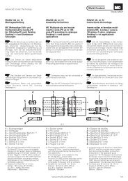
Lokator<br />
Locator<br />
Localisateur<br />
L<br />
®<br />
ill.2<br />
ill.3<br />
ill.4<br />
G<br />
H<br />
PV-CZM<br />
PV-CZ<br />
G H<br />
2,8 mm 3,2 mm - 4,8 mm<br />
4,0 mm 4,9 mm - 7,1 mm<br />
6,0 mm 6,5 mm - 7,6 mm<br />
PV-AZM<br />
Montagegerät<br />
Assembly tool<br />
Outil de montage<br />
C<br />
(ill.1)<br />
Assembly device with assembly tool<br />
(C), counter piece (D) and tapered<br />
spindle (E) in two diferent sizes:<br />
PV-WZ3 (Order No. 32.6000) for plug<br />
connectors size I + II, and PV-WZ3/III<br />
(Order No.. 32.6002) for plug<br />
connectors size I + II + III.<br />
(ill.2)<br />
Crimpzange PV-CZM<br />
Hinweise zur Bedienung<br />
der Crimpzangen siehe<br />
MA251-def (www.multicontact.com)<br />
oder<br />
Crimpzange PV-CZ für<br />
Kabelquerschnitt von<br />
2,5 mm2 und 4 mm2<br />
Bestell-Nr. 32.6008<br />
Anschlusskabel<br />
Zur Sicherstellung einer ausreichenden<br />
Dichtheit des Kabelausgangs<br />
der PV-Steckverbinder<br />
sind die Anschlusskabel<br />
in den, den IsolationsgehäusenzugewiesenenDurchmesserbereichen<br />
einzusetzen.<br />
Weiterhin empfehlen wir bei<br />
der Auswahl von doppelt isolierten<br />
Anschlusskabeln darauf<br />
zu achten, dass ein ausreichender<br />
Haftsitz zwischen<br />
den Isolationsschichten<br />
gewährleistet ist, der ein<br />
Verschieben der beiden gegeneinander<br />
und dieser auf<br />
dem Leiter ausschliesst.<br />
Kabelvorbereitung<br />
Hinweis:<br />
Anschlusskabel mit einem<br />
Litzenaufbau Klasse 2, 5 und<br />
6 können angeschlossen<br />
werden. Verzinnte Leiter<br />
sind vorteilhaft<br />
(ill.3)<br />
Durchmesser kontrollieren.<br />
G = Kabeldurchgang<br />
H = Kabel-Ø über Isolation<br />
(ill.4)<br />
Kabel abisolieren.<br />
Darauf achten, dass keine<br />
Einzeldrähte abgeschnitten<br />
werden.<br />
Empfohlenes Werkzeug:<br />
Abisolierzange PV-AZM, Bestell-Nr.<br />
32.6027.<br />
Typ Länge L (mm)<br />
PV-BP3/4 6 - 7.5<br />
PV-SP3/4 6 - 7.5<br />
PV-BP3/6 8.5 - 9.5<br />
PV-SP3/6 8.5 - 9.6<br />
Gegenhalter<br />
Counter piece<br />
Butée<br />
D<br />
(ill.2)<br />
Crimping pliers PV-CZM<br />
Notes to the operation of<br />
the crimping pliers,<br />
seeMA251-def<br />
(www.multi-contact.com)<br />
or<br />
Crimping pliers PV-CZ for cable<br />
cross section of<br />
2,5 mm2and 4 mm2<br />
Order No. 32.6008<br />
Connecting cable<br />
To ensure that the cable outlet<br />
of the PV plug connectors<br />
is sufficiently watertight, the<br />
diameter of the connecting<br />
cables must be within the<br />
ranges specified for the insulating<br />
casings.<br />
Further, we also recommend<br />
that when selecting a<br />
double insulated connecting<br />
cable that there is sufficient<br />
adhesion between the insulating<br />
layers and to the conductor,<br />
to prevent sliding.<br />
Cable preparation<br />
Important:<br />
Cables with class 2, 5 or 6<br />
construction can be connected.<br />
It is advantageous to<br />
use tinned conductors.<br />
(ill.3)<br />
Check diameter<br />
G= I.D. insulator<br />
H= O.D. over cable insulation<br />
(ill.4)<br />
Strip cable insulation.<br />
Take care not to cut individual<br />
strands.<br />
Recommended tool:<br />
Stripping pliers PV-AZM, Order<br />
No. 32.6027.<br />
Type Length L (mm)<br />
PV-BP3/4 6 - 7.5<br />
PV-SP3/4 6 - 7.5<br />
PV-BP3/6 8.5 - 9.5<br />
PV-SP3/6 8.5 - 9.6<br />
<strong>Multi</strong>-<strong>Contact</strong><br />
Konus<br />
Tapered spindle<br />
Cône<br />
E<br />
(ill.1)<br />
Dispositif de montage composé d’un<br />
outil de montage (C), d’une butée (D) et<br />
d’un cône (E) et disponible dans deux<br />
formats:<br />
PV-WZ3 (No. de Cde 32.6000) pour les<br />
connecteurs PV de taille I + II, et PV-<br />
WZ3/III (No. de Cde 32.6002) pour les<br />
connecteurs PV de taille I + II + III.<br />
(ill.2)<br />
Pince à sertir PV-CZM<br />
Notice d’utilisation des<br />
pinces à sertir, voir<br />
MA251-def (www.multicontact.com)<br />
ou<br />
Pince à sertir PV-CZ<br />
pour câble de section<br />
2,5 mm2 et 4 mm2<br />
No. de Cde 32.6008<br />
Câbles de raccordement<br />
Pour assurer une étanchéité<br />
suffisante de la sortie de câble<br />
du connecteur PV, utiliser<br />
des câbles de raccordement<br />
avec un diamètre sur<br />
isolant correspondant aux<br />
spécifications du capuchon<br />
isolant.<br />
Nous recommandons en outre,<br />
pour des câbles de raccordement<br />
à double isolation,<br />
de s'assurer qu'il existe<br />
entre les couches isolantes<br />
une adhérence suffisante<br />
pour empêcher un déplacement<br />
des couches l'une par<br />
rapport à l'autre et sur le conducteur.<br />
Préparation du câble<br />
Important:<br />
Les câbles de raccordement<br />
de classe de souplesse 2, 5<br />
et 6 peuvent être connectés.<br />
Les conducteurs étamés<br />
offrent des avantages.<br />
(ill.3)<br />
Contrôler les diamètres<br />
G=Ødepassage du câble<br />
H=Øducâble sur isolant<br />
(ill.4)<br />
Dénuder le câble.<br />
Veillez à ne pas couper les<br />
brins.<br />
Outil recommandé:<br />
Pince à dénuder PV-AZM,<br />
No.de Cde 32.6027.<br />
Type Longueur L (mm)<br />
PV-BP3/4 6 - 7.5<br />
PV-SP3/4 6 - 7.5<br />
PV-BP3/6 8.5 - 9.5<br />
PV-SP3/6 8.5 - 9.6
<strong>Multi</strong>-<strong>Contact</strong><br />
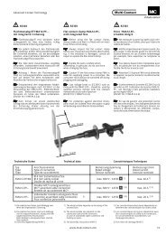
D<br />
Q<br />
max. 1 mm<br />
ill.6<br />
ill.7<br />
E<br />
ill.9<br />
ill.5<br />
4 mm 2 2.5 mm 2<br />
ill.8<br />
A<br />
B<br />
L<br />
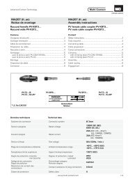
Crimpanschlüsse Crimp connections Raccords sertis<br />
Für den Leiteranschluß an<br />
die Crimphülsen der PV-<br />
Steckverbinder empfehlen<br />
wir die angegebenen Crimpwerkzeuge<br />
einzusetzen. Die<br />
Cromphülsen sind für flexible<br />
Leiter (Klasse 5 und 6)<br />
der genannten Querschnitte<br />
ausgelegt. Der Einsatz mehrdrähtiger<br />
Leiter in AWG Abmessungen<br />
ist möglich. Verzinnte<br />
Leiter sind vorteilhaft.<br />
(ill.5)<br />
Kabel bis zum Anschlag in<br />
die Crimphülse einstecken.<br />
Litze muss im Querloch (Q)<br />
sichtbar sein.<br />
Achtung:<br />
Alle Drähte der Litze müssen<br />
sauber in der Bohrung<br />
eingeführt sein und das<br />
Mass max. 1 mm darf nicht<br />
überschritten werden. Hülse<br />
mit Crimpzange verpressen.Crimpzangen-Selectorposition<br />
bzw. Crimpprofil (ill.6)<br />
gem. untenstehender Tabelle<br />
For the connection of the<br />
conductors to the crimping<br />
sleeves of the PV plug connectors,<br />
we recommend<br />
using the stated crimping<br />
tools. The crimping sleeves<br />
are designed for flexible conductors<br />
(class 5 and 6) of the<br />
stated cross-sections. <strong>Multi</strong>stranded<br />
conductors in<br />
AWG sizes may also be<br />
used. It is advantageous to<br />
use tinned wires.<br />
Crimpen Crimping Sertissage<br />
Crimpzangen<br />
Crimp tools<br />
Pinces à sertir<br />
Bestell.-Nr.<br />
Order No.<br />
No. de Cde<br />
PV-CZ 32.6008<br />
Crimpprofil<br />
ill.6 Crimp profile<br />
Matrice<br />
(ill.9)<br />
Gegenhalter (D) vorne aufstecken.<br />
Seite A auf Buchsen-Isolation,<br />
Seite B auf<br />
Stecker-Isolation.<br />
(ill.5)<br />
Insert cable into crimp sleeve<br />
up to stop. Stranded conductor<br />
must be visible in the<br />
sight hole (Q).<br />
Caution:<br />
Make sure all conductor wires<br />
are cleanly inserted into<br />
hole and max. dimension of<br />
1 mm is not exceeded.<br />
Crimp the sleeve with crimping<br />
pliers.<br />
Selector position or crimp<br />
profile (ill.6) according to the<br />
list below.<br />
(ill.9)<br />
Slip on counter piece (D)<br />
from the front. For sockets,<br />
side A towards the insulator.<br />
For pins, side B towards the<br />
insulator.<br />
Pour le raccordement des<br />
conducteurs dans les fûts à<br />
sertir des connecteurs PV,<br />
nous recommandons l'emploi<br />
des outils de sertissage<br />
spécifiés. Les fûts à sertir<br />
sont conçus pour des conducteurs<br />
souples (classe 5<br />
et 6) des sections mentionnées.<br />
L'utilisation de conducteurs<br />
multibrins en dimensions<br />
AWG est possible.<br />
Les conducteurs étamés<br />
sont recommandés.<br />
(ill.5)<br />
Insérer le câble dans le fût à<br />
sertir jusqu’en butée. Le câble<br />
doit être visible par<br />
l’orifice de contrôle (Q).<br />
Attention:<br />
Introduire soigneusement<br />
tous les brins du câble et respecter<br />
la cote maximale de 1<br />
mm. Sertir le câble dans le<br />
fût à sertir à l’aide de la pince<br />
à sertir.<br />
Position du sélecteur ou profil<br />
de sertissage (ill.6) selon<br />
la liste ci-dessous.<br />
Kabelquerschnitt<br />
Cable cross section<br />
Section du câble<br />
2mm 2,5mm 3,5mm 4mm 6mm<br />
14 AWG 12 AWG 10 AWG<br />
2 2 2 2 2<br />
1) 1)<br />
- 2,5 - - 4 - -<br />
1) nur für flexible Leiter<br />
1) Flexible cable only<br />
1) Uniquement pour câble<br />
(Klasse 5 und 6)<br />
(class 5 and 6)<br />
souple (classe 5 et 6)<br />
Montage Assembly Montage<br />
(ill.7)<br />
Vor der Montage die Montagevorrichtung<br />
justieren. Bei<br />
ausgefahrener Zugstange<br />
das Mass L einstellen auf:<br />
(ill.8)<br />
Konus (E) von hinten durch<br />
die Buchsen-Isolation bzw.<br />
Stecker-Isolation stossen<br />
bis Konusende fast bündig<br />
mit Isolation ist.<br />
(ill.7)<br />
Adjust the assembly device<br />
before assembly. With the<br />
drawbar extended, set the<br />
dimension L to:<br />
Montagegerät<br />
Assembly device L<br />
Dispositif de montage<br />
PV-WZ3 23,5 mm ± 1 mm<br />
PV-WZ3/III 13,5 mm ± 1 mm<br />
(ill.8)<br />
Push tapered spindle (E)<br />
through insulator until the<br />
end is nearly flush with insulator.<br />
(ill.7)<br />
Avant montage, ajuster le<br />
dispositif de montage en réglant<br />
la position de la tige de<br />
traction de sorte à respecter<br />
la cote L.<br />
(ill.8)<br />
Pousser le cône (E) par<br />
l’arrière du capuchon isolant<br />
jusqu’à ce que l’extrémité<br />
du cône soit pratiquement à<br />
fleur de l’isolant.<br />
(ill.9)<br />
Monter la butée (D). Pour les<br />
douilles, orienter la face A<br />
vers le capuchon isolant; pour<br />
les broches, orienter la face B<br />
vers le capuchon isolant.<br />
3/4<br />
®
(ill.11)<br />
Konus (E) an der Zugstange (K) des Montagegerätes<br />
(C) einhängen und Hebel soweit<br />
betätigen bis der Gegenhalter (D) am<br />
Winkel anliegt.<br />
Buchse bzw. Stecker in der<br />
Bohrung am Konus-Ende einführen. Hebel<br />
mit gleichmässiger Bewegung bis<br />
zum Anschlag umlegen. Dabei Buchse<br />
bzw. Stecker durch Druck auf das Kabel<br />
gleichzeitig nachstossen.<br />
Bei ganz umgelegtem Hebel Buchse bzw.<br />
Stecker mit der montierten Tülle nach hinten<br />
wegziehen.<br />
4/4<br />
®<br />
Industriealkohol<br />
Industrial alcohol<br />
alcool industriel<br />
ill.10<br />
(ill.10)<br />
Hinweis:<br />
Der Montagevorgang kann erleichtert<br />
werden, wenn der Kabelausgang der<br />
Steckverbinderisolation vor dem Einsetzen<br />
der Kontakte in Industriealkohol getaucht<br />
wird.<br />
ill.12<br />
(ill.12)<br />
Durch Kontrollbewegung sicherstellen,<br />
dass die Tülle auf dem Metallteil richtig<br />
eingerastet ist.<br />
Bei richtiger Einbaulage müssen die eingebauten<br />
Teile mit der Isolations-<br />
Stirnseite fluchten.<br />
(ill.13)<br />
Beiliegender Kleber<br />
“ Danger Do not disconnect under load”<br />
in der Nähe des PV-<br />
Kupplungssteckers anbringen.<br />
Cable routing*:<br />
(ill.10)<br />
Note:<br />
To facilitate installation immerse the insulation<br />
of plug connectors in industrial<br />
alcohol before inserting the contacts.<br />
(ill.11)<br />
Attach tapered spindle (E) to the pull rod<br />
(K) of mounting tool (C) and actuate lever<br />
until counter piece (D) reaches the bracket.<br />
Insert socket or pin into hole of tapered<br />
spindle.<br />
Carefully, shift lever to its stop position<br />
and at the same time push in the pin<br />
resp. the socket applying pressure to the<br />
cable.<br />
With the lever in the end position, pull off<br />
the mounted pin with insulator, resp. the<br />
mounted socket with insulator.<br />
ill.13<br />
(ill.12)<br />
Check to make sure the insulator is properly<br />
engaged on the metal part. If the installed<br />
parts have been assembled correctly,<br />
they will be flush with the end of<br />
the insulator.<br />
(ill.13)<br />
Attach enclosed sticker “ Danger Do<br />
not disconnect under load”<br />
as<br />
near as possible to the male cable coupler.<br />
K<br />
C E D<br />
* Beachten Sie die Spezifikationen des Leitungsherstellers betreffend Biegeradius<br />
* Refer to cable manufactures specification for minimum bending radius.<br />
* Se référer aux spécifications du fabricant de câbles pour un rayon de courbure minimal<br />
MA207-def-ALT<br />
� �<br />
06.2008 Index j<br />
Correct engagement:<br />
ill.11<br />
<strong>Multi</strong>-<strong>Contact</strong><br />
Stecker<br />
Pin<br />
Broche<br />
Buchse<br />
Socket<br />
Douille<br />
(ill.10)<br />
Remarque:<br />
L’emmanchement des contacts peut être<br />
facilité en plongeant au préalable les corps<br />
isolants dans de l’al-cool industriel.<br />
(ill.11)<br />
Accrocher le cône (E) à la tige de traction<br />
(K) de l’outil de montage (C) et manoeuvrer<br />
le levier pour se mettre en appui sur la butée<br />
(D) .<br />
Introduire la douille ou la broche dans le perçage<br />
du cône.<br />
D’un mouvement régulier, amener le levier<br />
en butée. Pousser en même temps la<br />
douille ou la broche en exerçant une pression<br />
sur le câble.<br />
Une fois le levier entièrement basculé, retirer<br />
par l’arrière la douille ou la broche avec<br />
le support monté.<br />
(ill.12)<br />
S’assurer que l’isolant est correctement<br />
monté sur la pièce métallique.<br />
Les pièces métalliques doivent être à fleur<br />
de la face avant de l’isolant.<br />
(ill.13)<br />
Coller l’étiquette<br />
“ Danger Do not disconnect under<br />
load”<br />
à proximité du raccord mâle PV.<br />
Änderungen vorbehalten / Subject to alterations / Modifications sous réserve<br />
Copyright by <strong>Multi</strong>-<strong>Contact</strong> AG, Switzerland / Solar line / 100<br />
Ex. / 04.2008<br />
�