Ballon de stockage combiné TERMO
Ballon de stockage combiné TERMO
Ballon de stockage combiné TERMO

You also want an ePaper? Increase the reach of your titles
YUMPU automatically turns print PDFs into web optimized ePapers that Google loves.
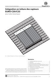
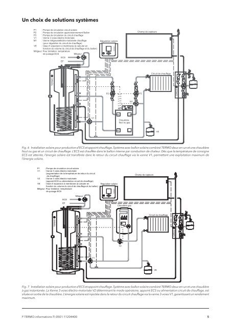
Un choix <strong>de</strong> solutions systèmes<br />
P1 : Pompe <strong>de</strong> circulation circuit solaire<br />
P2 : Pompe <strong>de</strong> circulation approvisionnement <strong>Ballon</strong><br />
P3 : Pompe <strong>de</strong> circulation du circuit chauffage<br />
V1 : Vanne 3 voies électro-motorisée<br />
M1 : Vanne mitigeuseélectro-motorisée chauffage<br />
(pour régulation du circuit <strong>de</strong> chauffage)<br />
VE : Vase d' expansion à membrane (à calculer en<br />
fonction du volume du circuit <strong>de</strong> chauffage et du ballon)<br />
Mitigeur: Pour limitation température<br />
<strong>de</strong> puisage ECS<br />
Mitigeur<br />
ECS<br />
EF<br />
Régulation solaire<br />
SUNGO<br />
Champ <strong>de</strong> capteurs<br />
Circuit <strong>de</strong> chauffage<br />
2<br />
<strong>TERMO</strong><br />
P1<br />
P2<br />
P3<br />
CIRCO<br />
M1<br />
V1<br />
Chaudière<br />
fioul ou gaz<br />
VE<br />
Fig. 6 Installation solaire pour production d’ECS et appoint chauffage. Système avec ballon solaire combiné <strong>TERMO</strong> <strong>de</strong>ux-en-un et une chaudière<br />
fioul ou gaz et un circuit <strong>de</strong> chauffage. L’ECS est chauffée dans le ballon interne par conduction <strong>de</strong> chaleur. Dès que la température <strong>de</strong> consigne<br />
ECS est atteinte, l’énergie solaire est transférée dans le retour du circuit chauffage via la vanne V1, permettant une exploitation maximum <strong>de</strong><br />
l’énergie solaire.<br />
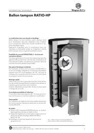
P1 : Pompe <strong>de</strong> circulation circuit solaire<br />
V1 : Vanne 3 voies électro-motorisée<br />
(augmentation <strong>de</strong> la température <strong>de</strong> retour du circuit<br />
<strong>de</strong> chauffage)<br />
V2 : Vanne 3 voies électro-motorisée<br />
(appoint ECS ou alimentation circuit <strong>de</strong> chauffage)<br />
VE : Vase d' expansion à membrane (à calculer en<br />
fonction du volume du circuit <strong>de</strong> chauffage et du ballon)<br />
Mitigeur: Pour limitation température<br />
<strong>de</strong> puisage ECS<br />
Régulation solaire<br />
SUNGO<br />
Champ <strong>de</strong> capteurs<br />
ECS<br />
EF<br />
Mitigeur<br />
Chaudière gaz<br />
Circuit <strong>de</strong> chauffage<br />
<strong>TERMO</strong><br />
P1<br />
CIRCO<br />
V2<br />
V1<br />
VE<br />
Fig. 7 Installation solaire pour production d’ECS et appoint chauffage. Système avec ballon solaire combiné <strong>TERMO</strong> <strong>de</strong>ux-en-un et une chaudière<br />
à gaz instantanée. La Vanne 3 voies électro-motorisée V2 déterminant le mo<strong>de</strong> opératoire, appoint ECS ou alimentation circuit <strong>de</strong> chauffage, est<br />
située en sortie <strong>de</strong> la chaudière. L’énergie solaire est injectée dans le retour du circuit chauffage via la vanne 3-voies V1, garantissant un ren<strong>de</strong>ment<br />
maximum.<br />
F-<strong>TERMO</strong>-informations-TI-0501-11204400 5